Measurement of the intensity of progressive ultrasonic ... · MEASUREMENT OF THE INTENSITY OF...
81
Measurement of the intensity of progressive ultrasonic waves by means of Raman-Nath diffraction Stapper, M. Published: 01/01/1974 Document Version Publisher’s PDF, also known as Version of Record (includes final page, issue and volume numbers) Please check the document version of this publication: • A submitted manuscript is the author's version of the article upon submission and before peer-review. There can be important differences between the submitted version and the official published version of record. People interested in the research are advised to contact the author for the final version of the publication, or visit the DOI to the publisher's website. • The final author version and the galley proof are versions of the publication after peer review. • The final published version features the final layout of the paper including the volume, issue and page numbers. Link to publication Citation for published version (APA): Stapper, M. (1974). Measurement of the intensity of progressive ultrasonic waves by means of Raman-Nath diffraction. (EUT report. E, Fac. of Electrical Engineering; Vol. 74-E-53). Eindhoven: Technische Hogeschool Eindhoven. General rights Copyright and moral rights for the publications made accessible in the public portal are retained by the authors and/or other copyright owners and it is a condition of accessing publications that users recognise and abide by the legal requirements associated with these rights. • Users may download and print one copy of any publication from the public portal for the purpose of private study or research. • You may not further distribute the material or use it for any profit-making activity or commercial gain • You may freely distribute the URL identifying the publication in the public portal ? Take down policy If you believe that this document breaches copyright please contact us providing details, and we will remove access to the work immediately and investigate your claim. Download date: 07. Sep. 2018
Transcript of Measurement of the intensity of progressive ultrasonic ... · MEASUREMENT OF THE INTENSITY OF...
Measurement of the intensity of progressive ultrasonicwaves by means of Raman-Nath diffractionStapper, M.
Published: 01/01/1974
Document VersionPublisher’s PDF, also known as Version of Record (includes final page, issue and volume numbers)
Please check the document version of this publication:
• A submitted manuscript is the author's version of the article upon submission and before peer-review. There can be important differencesbetween the submitted version and the official published version of record. People interested in the research are advised to contact theauthor for the final version of the publication, or visit the DOI to the publisher's website.• The final author version and the galley proof are versions of the publication after peer review.• The final published version features the final layout of the paper including the volume, issue and page numbers.
Link to publication
Citation for published version (APA):Stapper, M. (1974). Measurement of the intensity of progressive ultrasonic waves by means of Raman-Nathdiffraction. (EUT report. E, Fac. of Electrical Engineering; Vol. 74-E-53). Eindhoven: Technische HogeschoolEindhoven.
General rightsCopyright and moral rights for the publications made accessible in the public portal are retained by the authors and/or other copyright ownersand it is a condition of accessing publications that users recognise and abide by the legal requirements associated with these rights.
• Users may download and print one copy of any publication from the public portal for the purpose of private study or research. • You may not further distribute the material or use it for any profit-making activity or commercial gain • You may freely distribute the URL identifying the publication in the public portal ?
Take down policyIf you believe that this document breaches copyright please contact us providing details, and we will remove access to the work immediatelyand investigate your claim.
Download date: 07. Sep. 2018
MEASUREMENT OF THE INTENSITY OF
PROGRESSIVE ULTRASONIC WAVES BY MEANS
OF RAMAN-NATH DIFFRACTION
by
Drs. M. Stapper
Gro~i!r Mea;sutenrellt and Control
Dep1rt'tmE!'nt elf Electrical Engineering
Eindhoven University of Technology
Eind:hoven; The Netherlands
MEASUREMENT OF TRE INTENSITY
OF PROGRESSIVE ULTRASONIC WAVES
BY MEANS OF RAMAN-NATR DIFFRACTION
by
Drs. M. Stapper
T.H. Report 74-£-53
November '74
ISBN 90 6144 053 X
""So'''',: .
- 1 -
Contents
Sununary
I. Introduction
2. Derivation of the diffraction equation
3. Cqnsiderations on the diffraction equation
3.1. Parameters
3.2. The physical consistency of the solutions
3.3. The analytic availability of the solutions
4. Solutions of the diffraction equation
4.1. aaman-Nath condition
4.2. Bragg condition
4.3. Summary
5. Quantum-mechanical approach to the diffraction
phenomenon
6. Experiments
Appendix A. Aspects of general wave theory
Appendix B. Numerical methods. for computing the value
of v.
Appendix C. Abel inversion
Appendix D. The sound intensity
Acknowledgements
References
List of symbols
. " :'-'>""x!-.,~ '.~-~:, ",-
page
3
4
9
19
19
20
24
25
25
25
32
34
46
61
64
68
70
72
73
76
- 3 -
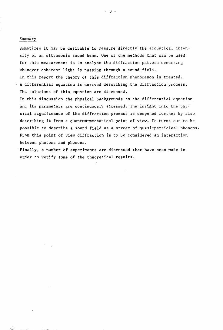
Summary
Sometimes it may be desirable to measure directly the acoustical inten-
sity of an ultrasonic sound beam. One of the methods that can be used
for this measurement is to analyse the diffraction pattern occurring
whenever coherent light is passing through a sound field.
In this report the theory of this diffraction phenomenon is treated.
A differential equation is derived describing the diffraction process.
The solutions of this,equation are discussed.
In this discussion the physical backgrounds to the differential equation
and its parameters are continuously st,essed. The insight into the phy
sical significance of the diffraction process is deepened further by also
describing it from a quantum-mechanical point of view. It turns out to be
possible to describe a sound field as a stream of quasi-particles: phonons.
From this point of view diffraction is to be considered an interaction
between photons and phonons.
'Finally, a number of experiments are discussed that have been made in
order to verify some of the theoretical results.
- 4
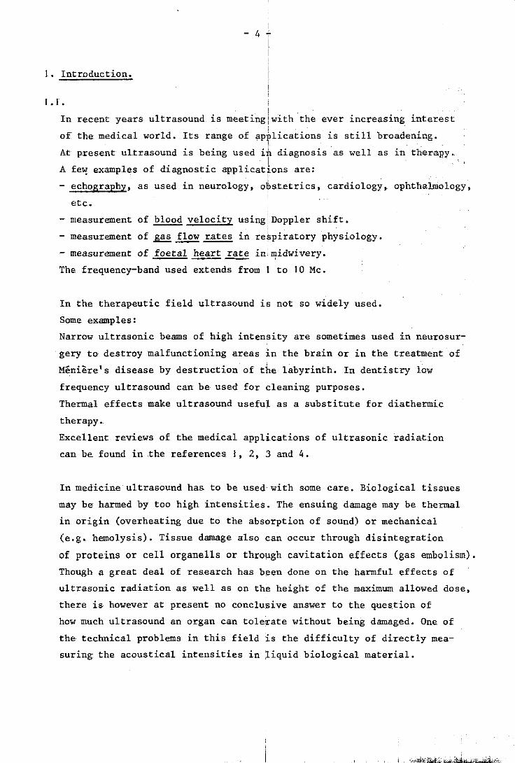
1. Introduction.
1.1. i
In recent years ultrasound is meetingiwith the ever increasing interest i
of the~ medical world. Its range of applications is still broadening. ,
At p~resent ultrasound is being us.ed iii diagnosis as well as in therapy. I
A few examples of diagnostic applications are: • I
- echography, as used in neurology, obstetrics, cardiology,. ophthalmology,
etc.
- measurement of blood velocity using'Doppler shift.
- measurement of ~ flow rates in re~piratory physiology.
measurement of foetal heart rate inill!idwivery.
The frequency-band used extends from 1 to 10 Me.
In the therapeutic field ultrasound is not so widely used.
Some examples:
Narrow ultrasonic beams of high intensity are sometimes used in neurosur
gery to destroy malfunctioning areas 1n the brain or in the treatment of
Meniere's disease by destruction of the labyrinth. In dentistry low
frequency ultrasound can be used for cleaning purposes.
Thermal effects make ultrasound useful as a substitute for diathermic
therapy.~
Excellent reviews of the medical applications of ultrasonic radiation
can be. found in .the references. 1, 2, 3 and 4.
In medicine ultrasound has to be used with some care. Biological tissues
may be harmed by too high intensities. The ensuing damage may be thermal
in origin (overheating due to the absorption of sound) or mechani.cal
(e.g. hemolysis). Tissue damage also can occur through; disintegration
of proteins or cell organells or through cavitation effects (gas embolism).
Though a great deal of research has been done on the harmful effects of
ultrasonic radiation as well as on the height of the maximum allowed dose,
there is however at present no conclusive answer to the ques~tion of
how much ultrasound an organ can tolerate without being damaged. One of
the technical problems in this field is the difficulty of directly mea
suring the acoustical intensities in ~iquid biological material.
, "'-,
- 5 -
This report aims to contribute to these measuring techniques thus
hoping to be of some help in overcoming the existing difficulties.
From literature we know of quite a number of methods being used for mea
suring acoustical intensities in a more or less direct way (ref. 6, 7,
8,9, 10).
Some.of these methods:
1. the calorimeter method, in which the increase of temperature is
measured in a medium that completely absorbs the ultrasonic wave.
This method is te~hnically difficult, not very accurate and can
only be applied to high sound intensities.
'2. the measurement of the Langevin ra4iation pressure caused by the
sound field. This method is also rather difficult because of the
very small values of this kind of pressure. Moreover the theoretical
background to radiation pressure has not as yet been very firmly es
tablished in literature.
3. the method using the reciprocity principle. The efficiency of an
ultrasonic transducer can be measured by the emission of a short
wave train which having been reflected must be received again by
the same transducer. A difficulty in this method lies in the trans
mission of short, sharply limited wave packets.
4; the optical method. This method makes use of the fact that a sound
field will act as a phase grating to any beam of coherent light
falling through it perpendicularly.
The latter method has compared to the former ones the following advantages:
1. A light beam is used as a measuring probe. Since the wavelength of the
light is very small compared to the wavelength of the sound, the sound
field will scarcely be disturbed by the measuring action. The object
to be measured is influenced by the measurement but to a negligible
degree.
2. When a laserbeam is used as a light beam its small diameter permits
the measurement of local sound intensities instead of only measuring
intensities averaged over the gross area of the sound field. Thus
it becomes possible to scan the sound field in small steps probing
the spatial distribution of acoustic energy in this field.
- 6 , ,
3. The method not only gives informJion on the intensity of ",the sound
b 1 . f C 11" "h' I ut a so on 1tS wave orm. onsequent y 1t g1ves 1ns1g t 1nto t,e I '
degree to which the sound wave ha~ been distorted. 1
4. From an instrumental point of vie~ this method is a very--simpl'e one., ,
The following disadvantages have to b~ mentioned also: • I
1. The method is rather time-conswni~g, due to the fact that the soond,
field has to be scanned area afte':' area by a thin light beam.
2. The method can only be applied to :perfectly plane sound waves.
The advantages mentioned make it wo.rtl).while to evaluate further this
optical method.
1 .2 •
In 1922 Brillouin (ref. 11) predicted ion theoretical grounds the so_
called Bragg diffraction of light, wh¢n this light is incident at a cer- ,
. tain angle upon a sound wave; this ph¢nomenon is completely analogous to
x-ray diffraction in crystals.
The so called Raman-Nath diffraction occurs, when the light is perdendi
cularly incident upon a sound wave. This has been discovered in 1932
by Debije and Sears in the United States (ref. 12) and independently by
Lucas and Bicquard in France (ref.B), In the years 1935-1936 the theo
retical explanation of this kind of d~ffraction has been set out b.y
Raman and Nath in a series of papers ~ref. 14). The validity of this
Raman-Nath theory was confirmed by the experiments of Sanders in 1936
(ref. 15) and Nomoto in 1940 (ref. 29)1. Meanwhile the frequency shifts of
the diffracted beams in bo.th B.ragg and Raman Nath diffraction had been
discovered by Debije, Sack and Coulon'in 1934 (ref. 16).
After the second world war the classid Raman-Nath theory \,las developed
both experimentally and theoretically iby a number of investigators:
Klein, Co,ok, Hargrove, Hiedemann, Murqy, Mertens, etc. (ref. 17-26).
They refined the Raman-Nath theory ta~ing into account the influence of
the finit'e width of the light beam, of a possible oblique incidence of
the light, of the distortion of the sound wave and of the presence of , standing waves in the sound field. The;y also developed several mathematical
methods capable of solving the occuring differential equations numeri
cally (ref. 27, 28)
- 7 -
A very profound mathematical exploration of the problem can be found
in the book of Berry (ref. 29).
The work of Klein and Cook (ref. 20) makes clear that Bragg and Raman
Nath diffraction are in fact two different manifestations of one single
diffraction phenomenon.
I. 3.
Consider a light beam falling (almost) perpendicularly through a beam
of progressive sound waves (fig. 1.1). When the light beam emerges from
the sound field, it is found to have been split up into a certain num
ber of discrete, divergent light beams. On a screen placed behind the
sound field these light beams will produce a series of light spots: the
so-called diffraction pattern.
The distance' between these light spots is a measure to the frequency of
the fundamental tone of the sound; the intensity of the spots is a
measure to the intensity of the sound. Thus it is possible to determine
the sound intensity by measuring the light intensities in the diffraction
pattern. To determine the absolute sound intensity one only needs to mea
sUre relative light intensities. In the foregoing enumeration this has
been called the "optical method". The remainder of this report will deal
with this method.
In Chapter 2 we shall derive the diffraction equation, i.e. a set of si
multaneous differential equations describing the distribution of light
over the diffraction orders.
In Chapter 3 the properties of this equation will be discussed. In Chap
ter 4 the diffraction equation will be solved. In doing this we shall
find - depending on the values of the coefficients - a number of different
types of solutions.
In all these chapters the physical meaning of the results thus acquired
will be continuously stressed. In this way we hope to achieve as much
insight as possible into the physical backgrounds to the light-sound
interaction. It seems that this insight can be deepened by describing
this type of interaction from a quantum-mechanical point of view also.
Therefore such a description will be given in Chapter 5.
Chapter 6 will deal with experiments that have been made in order to
verify the theoretical results.
8 -!
I Finally some numerical methods will b~ discussed that can be used in
the evaluation of the results of the. jeasurement s.
2. Derivation of the diffraction equation.
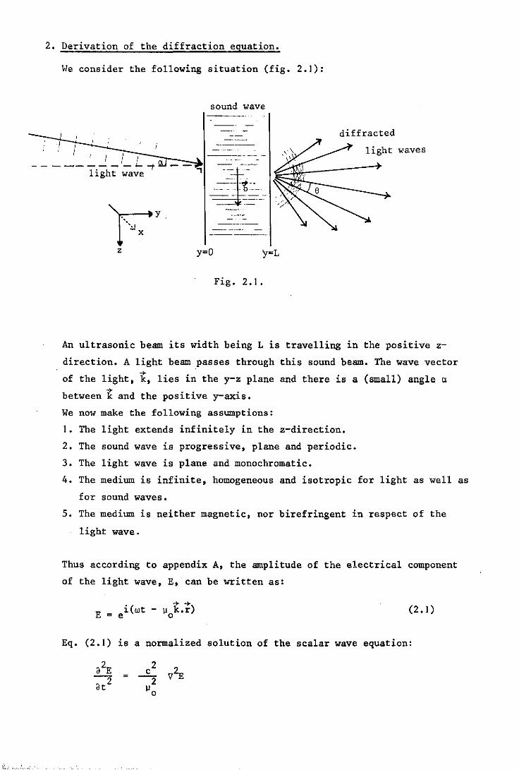
Vie consider the following situation (fig. 2.1):
sound wave
I"fl ~~_J ----I , / I I --------
diffracted
light waves
---------~~ ---light wave ---]-'
-~1--- _~' ,,,,' e ----- "
F" y, -- - '/
'" -x ______ _
z y=O y=L
Fig. 2.1.
An ultrasonic beam its width being L is travelling in the positive z
direction. A light beam ,passes through this sound beam. The wave vector . ~. .
of the 11ght, k, 11es 1n the y-z plane and there is a (small) angle ~ ~ . . .
between k and the pos1t1ve y-ax1S.
We now make the following assumptions:
I. The light extends infinitely in the z-direction.
2. The sound wave is progressive, plane and periodic.
3. The light wave is plane and monochromatic.
4. The medium is infinite, homogeneous and isotropic for light as well as
for sound waves.
5. The medium is neither magnetic, nor birefringent in respect of the
light wave.
Thus according to appendix A, the amplitude of the electrical component
of the light wave, E, can be written as:
E = • ( -+- -+-) 1 wt - ]J k.r
e 0 (2.1)
Eq. (2.1) is a normalized solution of the scalar wave equation:
- 101-
If Y < 0,. II is a constant: II = II • Ifl' 0 < y, <:L the refractive index II o
varies in space and time, since the sound wave can be regarded as a pres-
sure wave and in' general the refract ire index depends on pressure. By
these. variations of the refractive in1!ex the light wave is being influenced i
and. as a. res.ult i.ts amplitude may be ¥ritten in the interval 0 < y < L
as:
E = B(y, . ( ...... )
t) 1 wt - llok.r Z, .e (2.2)
in which B is an unknown function accounting for the variations of refrac
tive index.
Since the sound wave is periodic, B will also be periodic with respect to
the variable (rlt - bz), rl and b being, respectively the frequency and the
wave number of the fundamental component of the sound wave. Therefore, B
can be expanded in a Fourier s.eri.es to this variable:
B(y, z, t) = A (y).ein(rlt - bz) n
n=-~
Eq. (2.2) and (2.3) give
00 ......
E = r A (y) .ei(wt + nrlt - nbz - llok.r) n .
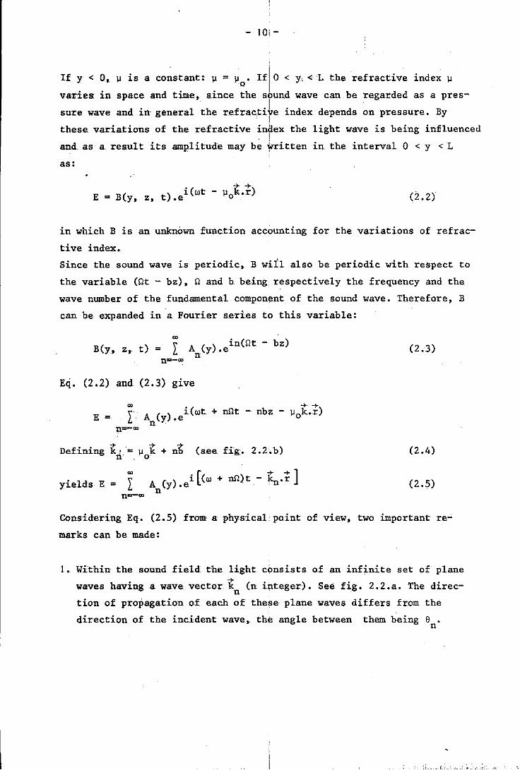
Defining k! = II k + nb (see fig. 2.2'.b) n' . 0
yields E = A (y) .ei [(w n
...... ] + nrl)t- ky,.r
(2.3)
(2.4)
(2.5)
Considering Eq. (2 .• 5) from' a. physical point of view, two important re
marks can be made:
I. Within the sound field the light cimsists of an infinite set of plane . ... ( waves hav1ng a wave vector knn integer). See fig. 2.2.a. The direc-
tion of propagation of each of these plane waves differs from the
direction of the incident wave, the angle between them being e • n
""'""-r------~ Y )a
a. z
- II -
Fig. 2.2.
Regarding fig. 2.2.b we find for 8 : n
nb + )J k sina o tan(8n + a) = --;--"--)J k cosa o
If a and 8 are so small that n
then
tan(8 + a) ~ 8 + a n n
tano:
eaSel
A = n-T
a
""'""--;-----~ y
nb
b. z
+ tancx
(2.6)
The angle between two light waves with successive n is equal to the ratio
of the optical to the acoustical wavelength.
2 Th f of the nth . h f d' ff d l' h . • e requency wave Ln t e set 0 L racte Lg t waves LS
"'n = w + nO
the sound.
obviously the frequency of the light has been altered by
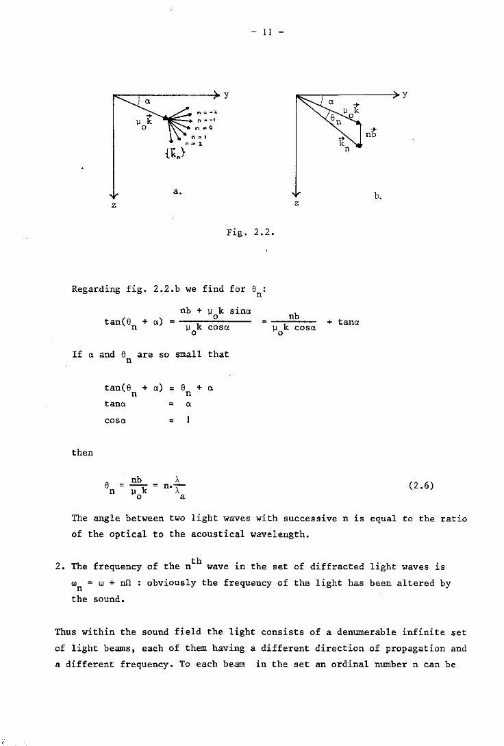
Thus within the sound field the light consists of a denumerable infinite set
of light beams, each of them having a different direction of propagation and
a different frequency. To each beam in the set an ordinal number n can be
- 12 !
assigned as indicated in fig. 2 • .3.
n w LIE n
-2 w - 2n -2M
k b -1 w - n -fin 110
.J 0 0 w
+1 w + n fln
+2 w + 2n 2fln Fig. 2.3.
th Since the frequency of the n order beam is wn = W + on the energy of
each photon in this beam is:
E = -fi(w + on) = E + LIE, n 0
E being the photon energy of the incident beam. o
Obviously photon energy increases in those beams, that are diffracted in
the positive z-direction and decreases in those, diffracted in the negative
z-direction. Since there is no absorbtion of light in the medium the
energy of all the photons together is C;onserved. Thus the alterations
of photon energy are caused by the exctiange of energy between photons. As , direct energy exchange between particles can only take place in the case
of a collision and since the photons all travel in the same direction and
therefore never collide, we are lead to the conclusion that the sound
field acts as an "energy carrier" that ;provides the transport of the
energy that has been involved in the exchange process. This conclusion is
supported by the disappearance of diffr,action whenever the sound field is
removed.
The energy transport by the sound fieldi is strongly quantized: only integer
multiples of hn can be transported. Thi,s means that energy packets can be
found in the sound field travelling (having a velocity ca in the positive
z-direction) from one photon to another,. We· may consider these energy
quanta as quasi-particles and may all them phonons. The energy of such a
phonon is of course:
E = 1'ir. q
- 13 -
(2.7)
In the diffraction process also the direction of a photon has been altered.
Th~refore in addition to the energy exchange there has to be momentum
exchange as well. -+
The momentum, p , of a photon in the incident light beam is (if a = 0): o
.e y -+
= 1'ik.e y
-+ The momentum, PI' of a photon in the first order diffracted beam is:
-+ 1i(w+r.) (-+ e -+ • PI = e .cos + e .s~ne) c y z
Assuming that: r. + w = w
cose = sine = e = b/k
then:
p = -fik Iy The y-component remains unchanged during diffraction.
Plz =-fib
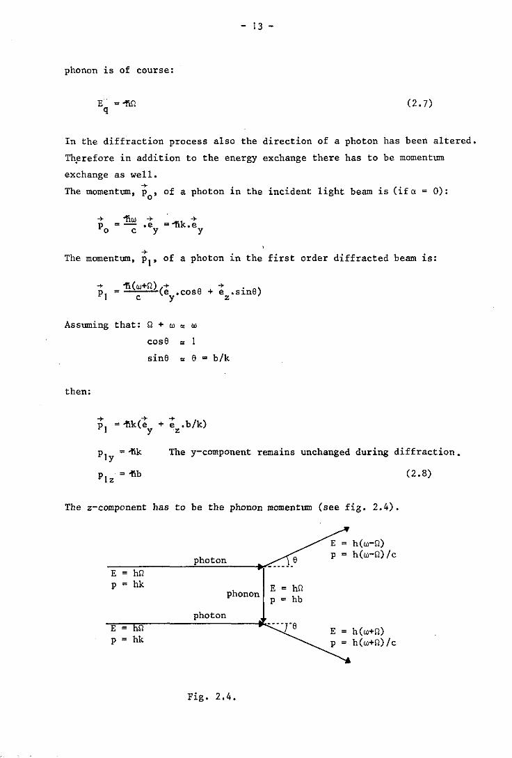
The z-component has to be the phonon momentum (see fig. 2.4).
E = hr. p = hk
E = r. p = hk
photon
phonon
photon
Fig. 2.4.
E p
= h(w-r.) = h(w-r.)/c
= hr. = hb
= h(w+r.) = h(w+r.)/c
(2.8)
- 14 -
In Chapter 5 this quantum-mechanical fPproach to the diffraction pheno
menon will he discussed in more detai~. We will end our physical disgres-, sion in stating emphatically that a pllOnon introduced above as an ener
gy.momentum packet, may ~ be considered a real particle.
Returning to the original subject the' refractive index of the medium will
now be under discussion.
Within the sound field this refractive index·is a function of z. We can
write:
~I is the pert~rbation of ~ caused by the sound.
Also
2 2 2110~1
2 II (z) = llo + + III
Being 2 2 write this as; llo » III we can
2 2 211011 1 \1 Cz) = 110 + C2.9)
III has its origin in the sound, and is consequently a periodic function
of z. Expanding \1 1 in a Fourier serie~ gives:
lJ 1 = I lls sinCsbz - os) s=1
8 L~ the relative phase of each term, s
°1 = 0
Eq. (2.9) now becomes:
2 2 \' \l = llo + 2110 L II sinCsbz - 0) s. S
s
e i(sbz - c )
s - e
-i(sbz - c ) s (2.10)
This apparently clumsy way of expandi~g in a complex Fourier series is
necessary in order to avoid negative values of s.
Eq. (2.10) includes all possible periodic functions Il(Z).
- 15 -
Let us now consider the wave equation of the light in the sound field:
We define the time-independent wave function ¥ as follows:
iwt E(y, z, t) = ¥(y, z).e
Substitution into (2.11) yields:
= -2
)J (z) 2 '" 2 .00.T
C
(2.11 )
(2.12)
(2.13)
In this we have tacitly assumed that w has the same value in all eigen
functions ¥ , which are solutions of (2.13). This is equivalent to the n
assumption that un « w.
It will later be seen that, if Inl increases, ¥ will very rapidly conver-n
ge towards the zero function, so that in fact only those cases are rele-
vant where Inl < 20.
As win % 10-8, the assumption un « W appears to be soundly based.
Since )J2(z) is periodic, Eq. (2.13) represents a so-called Mathieu
equation. This equation cannot be solved analytically. Berry (ref. 29)
has thoroughly investigated Eq. (2.13) in order to find approximate solu
tions of it, but without much success.
A better way of dealing with Eq. (2.13) can be found in rewriting the
equation in a different form (ref. 18). The necessary tools to perform
this transformation have already been prepared in the previous section.
Eq. (2.5) for instance after substitution of (2.12) and since un « w,
shows that solutions of (2.13) must have this kind of shape:
¥(y, z) = n=-co
.'" ... -1k .r . n A (y).e n . (2.14)
- 16 -
, Eq.s. {2.W) and (2.4) are .expressions , for "2(z) and k • respectively.
n
s s 0) -i (8bz - a J - e
-+ -+ -+ -+-+ k .• r = ()l k + nb).r = )l key cosa + z sinal + nbz • -n 0 0
since
-+ k .e x x
-+. + k .e
y y -+
+ k .e z z
(2.15)
After substitution of (2.15) we differentiate (2.14) twice and get:
I [;;2An _ 3An .2i)l k cosa _ A {n2b 2 + )l2k2 +
3 2 3y on 0 n y
This is an expression for the left hand side of (2.13).
By substituting (2.10) and (2.14) .an expression can be found for the
right hand side:
2 2 \,[22.2 \' )l (z).k .9 = L' k)l - 1k)l 'L o 0 n s {
i(sbz lls ~ e
-0 ) s
]
. -+-+ -i(sbz - as) -inbz -1\1 k.r
- e .A .e '. e 0 n
• -+-+ -1.11 .k.r . 1
o Y1e ds: Equating both expressions and .dividing through by e
1 [:> -:n -''''. ~ •• - An { .;, • ',.obk sina.e =
]
-inbz
ik2)l )l .A • e i(s-n)bz -ia
= I I s .e
o s -n n s
ik2)l )l .A .e -i(s+n)bz +ia
- I I s .e o s ·n n s
- 17 -
-ibz This is an equation is power series of e
for all z, if it holds for each power of
The equation only holds -ibz
e separately. Thus:
+ 2bk\l n o sino} =
-i5 = \ ik2\l \l.A .e s
l. 0 '5 n+s s
2. +i5 - \ ik \l \l.A .e s Los n-s s
Because A is a slowly varying function of y, the term n <lA
n pared to (k.dn
) and can be neglected (to be proved in
A rearrangement of the remaining terms ,leads to:
dA -io d/ + /:
s 2 coso
A .e s - \ n+s l.
s
The following parameters may now be defined:
v. = k\l L s 0
Q b2L =--k\l . 0
-k\l S
0 sinet =--b
+io s .A .e n-s
<l2A (----n) is small com-dl section 4.1.1).
=
(2.16)
(2.17)
(2.18)
(2.19)
'" Substituting these parameters and using coso'" I, Eq. (2.16) changes
into its final shape, the diffraction equation:
dA I t +io -io J {"n n s s .!.!h -d - 2L·/: v.A.e - v.A.e = 2L (n -n s ~s s Ms s
26) .A n
(2.20)
If v = 0 for s + I (sinusoidal sound wave), then (2.20) reduces to: s
-....!! _ .L _ - .!.!h _ dA [ J {,.,n dy 2L An-I An+1 - 2L (n 26).An (2.21)
Each of these two equations gives a complete description of the diffrac
tion process.
- 18 -
Ro,th equations in fact are infinit¢ sets of coupled, linear differential
equations.
The set (2.20) is identical to the Mathicu equation (2.13).
Neither (2.20), nor (2.21) can be solved analytically, except in some
special cases.
The diffraction equation holds und:er the following conditions:
III « I
Q « w
a « I
d2A equivalent to __ n «
d/ UA
n k· dy
used in deriving Eq .• (2.13)
this means coso: !:::
(see sect. 4. I. I )
- 19 -
3. Considerations on the diffraction equation.
The diffraction equation contains three parameters. We shall briefly dis
cuss all three:
v =.klJ L s s IJ is directly related to the amplitude of the sth har-
s monic of the ultrasonic wave. kL is the path length of
the light through the sound as expressed in radians.
Therefore v = klJ L represents the absolute sound inten-. s 0
sity integrated along the light path, and may conse-
quently be considerec\ to be "the total amount of sound
intensity met by the light".
This parameter is related to the angle of incidence (l
between the light and the sound beam. As k » b, lei will in the case of (l increasing increase very rapidly
and may reach very high values.
v and B are built from quantities, which can easily be s varied. Q, however, depends on the more constant quan-
tities: wavenumber of light and sound, refractive index
and width of the sound beam. Since Q depends quadrati
cally on b, Q will vary greatly when the sound frequency
is changed. The value of Q determines whether and in what
form diffraction will occur. In Chapter 5 the physical
significance of Q will be made clear.
It is important to realize that the parameters v, e and Q are dimension
less as well as being independent of each other. Consequently any two
experimental systems different in many ways but characterized by the
same values of v, e and Q will give rise to the same diffraction phenomena.
The values of these three parameters are the necessary and sufficient in
formation for the description of a certain experimental situation.
Besides these parameters only the quantity L occurs in the diffraction
equation. Since L is also the length of the integration path, it will dis
appear on integration. At first sight it seems strange to find the length
of the integration path as a coefficient in a differential equation. We
- 20 -
shall deal in more detail with the backgrounds to this subject in Chapter
5.
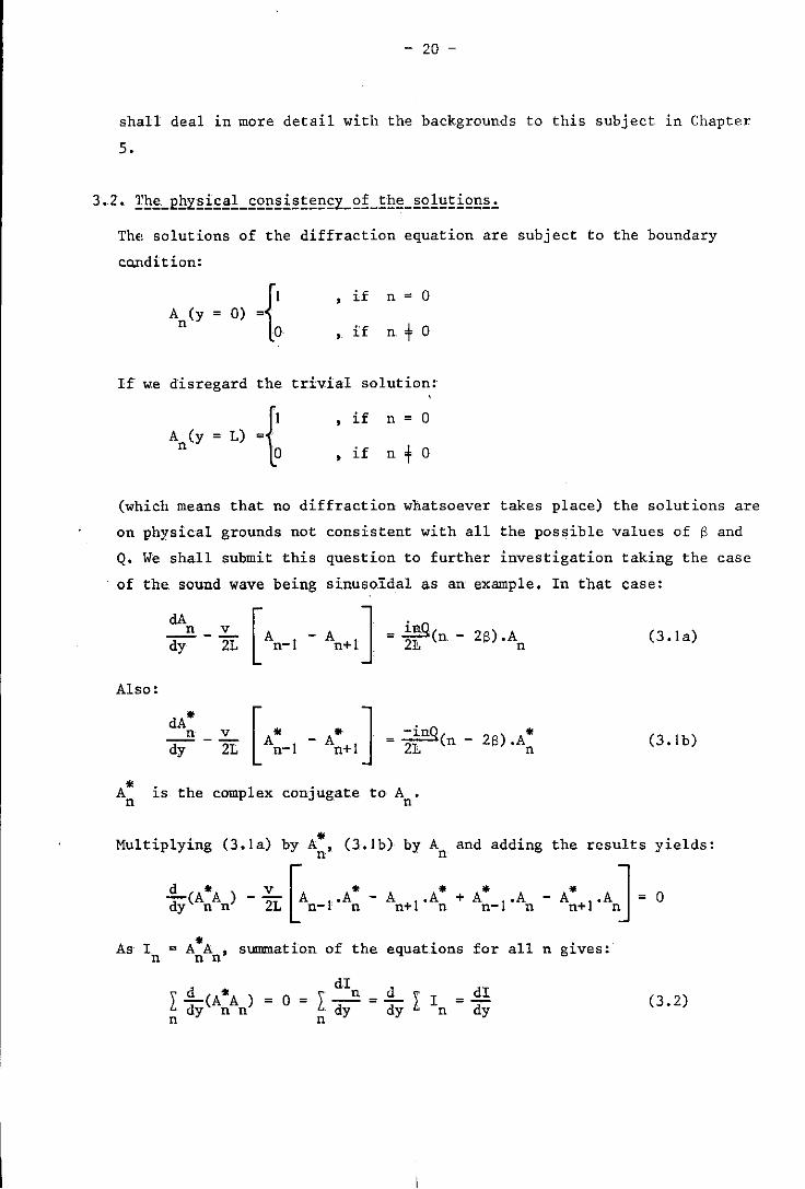
The, solutions of the diffraction equation are subject to the boundary
co.ndition:
if n = 0
,if n + 0
If w:e disregard the trivial solution:
if n = 0
,if n + 0
(which means that no diffraction whatsoever takes place) the solutions are
on physical grounds not consistent with all the possible values of 6 and
Q. We shall submit this question to further investigation taking the case
of the. sound wave being sinusoidal as an example. In that case:
n v lI'tQ cIA [ J' ---- A -A = n-dy 2L n-I n+l. 2], ( 26) .A
n (3.1 a)
Also:
[" -"J-~ - " An_1 An+1 - 2], (n 26).An (3.1 b)
A" is the complex conjugate to A • n n
Multiplying (3.la) by A:, (3.lb) by An and adding the results yields:
-2-(A"A)-v2 [A I.A"-A I.A"+A"I.A dy n n L n- n n+ n n- n - A'" I· A J = 0 n+ n
As I = A"A summation of the equations for all n gives: n n n'
L dd' (A" A ) = 0 = L ddIn
= ddy I In = ddyI y n n y n n
(3.2)
- 21 -
This means that (if n « w) the total intensity of the light wave is con
served. No permanent energy transport takes place from light to sound or
vice versa. Energy is only transferred between the light waves of diffe
rent diffraction orders; to be more precise between the light waves of
successive diffraction orders (6n = I).
A can be written in modulus and argument notation as: n
A n
a n
real (3.3)
A is the amplitude of the light beam not diffracted by the sound. Hence o arg(A ) is independent of y and according to the boundary condition at
o y = 0 A has to be real. ~ (y) =' O.
o 0
Substituting (3.3) into (3.la) yields:
[dan + 1'a d~nJ i~n(Y) v I i~n_I(Y) dy n dy·e -·2L Lan-I·e
i~n+1 (y)] - an+1 ·e =
(3.4)
This equation only holds for all y, if the exponent of all its terms is
the same. Thus ~ (y) = cj> (y), if m+n. n m Translated into' physical terms this means that phase synchronization has
to exist between light beams of different orders in order to make energy
transfer possible. Since ~ (y) = 0, ~ (y) = 0 for all n. o n' Applying this result to (3.4) gives:
Since I = a2, mUltiplying by a and summation of the equations for all n n n n
gives:
l: n
a • n
da ----B = dy
dI ! l: dyn = l:
n n
Using (3.2) the result is:
l: nQ(n - 2S).I = 0 n
n
inQ 2L (n - 2S).In
(3.5)
- 22 -
The diffraction equation itself is a (good) approximation. Therefore (3.5)
is also an approximation and may b'e written as:
L nQ(n - 2S)I ~ 0 n
n (3.6)
Since (3.6) has been directly deri~ed from the diffraction equation it
can be considered a basic condition that must always be fulfilled. It
deals with physical principles like phase synchronization and the conser
~ation of energy. And consequently (3.6) is a constraint to the diffraction
equation determining the physical consistency of its solutions.
The solution
if n + 0
if n = 0
(no diffraction) is the only one that is consistent with (3.6) for all the
possible ~alues of Sand Q.
All solutions in which In + 0 if n + 0 - that is, all solutions implying the
occurrence of a certain kind of diffraction - impose se~ere constraints
upon Sand Q in order to be c·onsistent with (3.6). In fact there are -
with respect to Sand Q - only three conditions under which diffraction can
occur.
1. 2S = m, m integer. Bragg condition.
2. Q « 1, S = O.
The angle of incidence Il of the light wave is in
this case: Il = - mb/2k~ • o
To satisfy (3.6) the solutions of the diffraction
equation must ha~e this kind of shape:
In = 0 if n + m and n + O.
Only two diffraction orders are present: the zeroth th and the m order. X-ray diffraction on crystals be-
longs to this kind of diffraction.
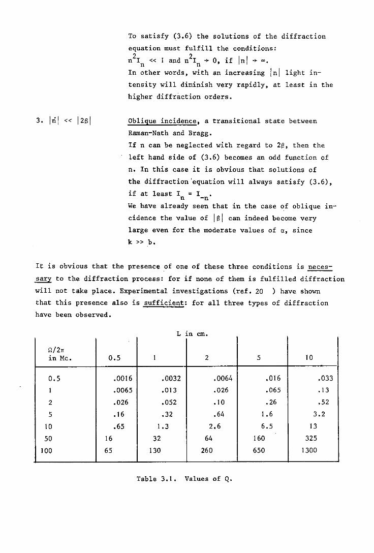
Raman-Nath condition.
Q « 1 means:
1. the sound frequency is not too high,
2. the sound beam is not too wide.
See table 1.
To satisfy (3.6) the solutions of the diffraction
equation must fulfill the conditions:
n2I «1 and n2I + 0, if Inl + 00. n n
In other words, with an increasing Inl light in-
tensity will diminish very rapidly, at least in the
higher diffraction orders.
Oblique incidence, a transitional state between
Raman-Nath and Bragg.
If n can be neglected with regard to 2S, then the
left hand side of (3.6) becomes an odd function of
n. In this case it is obvious that solutions of
the diffraction 'equation will always satisfy (3.6),
if at least I = I n -n We have already seen that in the case of oblique in-
cidence the value of lsi can indeed become very
large even for the moderate values of a, since
k » b.
It is obvious that the presence of one of these three conditions is neces
sary to the diffraction process: for if none of them is fulfilled diffraction
will not take place. Experimental investigations (ref. 20 ) have shown
that this presence also is sufficient: for all three types of diffraction
have been observed.
L in em.
fJ./2n in Mc. 0.5 1 2 5 10
0.5 .0016 .0032 .0064 .016 .033
1 .0065 .013 .026 .065 .13
2 .026 .052 .10 .26 .52
5 .16 .32 .64 1.6 3.2
10 .65 1.3 2.6 6.5 13
50 16 32 64 160 325
100 65 130 260 650 1300
Table 3.1. Values of Q.
- 24 -
The possibility of solving the diffraction equation analytically has
been very thoroughly investigated (ref. 20,29). The results of this
investigation give the appearance that the diffraction equation can be
soIved analytically if and only if one of the following conditions has
been fulfi lled:
1. The right hand side of the diffraction equation equals zero.
This will occur,if a) Q « 1 (Raman-Nath condition).
b) 2S = m, m integer (Bragg condition) •
. 2. In I is negligible with regard to 12s I. (oblique incidence).
In view of the thoroughness,whereby this matter has been explored -
particularly by Berry (ref. 29) - there seems to be no doubt that with
the exception of these two no other conditions for obtaining analytical
sOlutions can be found.
When comparing the abovementioned conditions with the conditions for
physical consistency deriv.ed in section 3.2, we find that the two sets
of conditions correspond completely.
Hence we may conclude that:
the diffraction equation can be solved anaZyticaZZy, if and
only if the soZutions are physicaZZy consistent.
On .the basis of this conclusion we can start in the next chapter to solve
the diffraction equation in all those instances, where diffraction occurs.
- 25 -
4. Solutions of the diffraction equation.
The. solutions are subject to the boundary condition
II, A (y=O) = n"
0,
if n = 0
if n + 0
In addition the equation is subject to the constraint of the integration
path having to extend from y = 0 to Y = L. The reason is that the sound
field does not extend. beyond y = L and that no diffraction will take place
outside that limit.
In this case the diffraction equation is:
Since Bessel functions of the first kind obey:
d -d J (ay) y n
(4. I)
it will be clear that the general solution of (4.1) will have to be:
A (y) = J ( ~) n n L
With the boundary conditions given the amplitudes of the diffraction
maxima will be
A = J (v) n n (4.2a)
and the intensities
I = J 2(v) n n (4.2b)
- 26 -
~~!!.'~!~~.:.
]. Since J 2(x) = J2 (x) for all n, the diffraction pattern will be syro-
n -n metric: about the zeroth order maximum.
2. It gives an N, such that I will be a monotone decreasing function of n
n" if n > N.
3. A (y) = J (vy/L) gives by series expansion of the Bessel function: n n
d2A dA n v n
di ~ '1:' dy
d2A dA holds
n kll]
n Since v = kll]L,
d/ ~
dy
d2,. dA ] , then
n k -1! If 11] « d/
« dy
This is a proof of the proposition made on page ]7.
4. The assumption 11] « ] only holds if v is not too large. This means in
practice that (4.2) only holds if v < 6.
Since 12bl » Inl the diffraction equation has the form:
dA [ ] ~ n v 1n S ---A -A =- .A dy 2L n-] n+ ] L n (4.3)
It can easily be proved by substitution that the general solution of this
equa.ion must be (ref. ]4, 20):
inQS [ - 2L'y 2v An (y) = e • I n QS , ~J S1n 2L
With the given boundary conditions this yields:
-! inQS [ A =e .J v
n n (4.4a)
- 27 -
and
(4.4b)
1. Q may not become too large. According to (2.18) and (2.19):
s = - bL sin", Q
Therefore in the c~s'e of Q being too large, I s I would not grow fast
enough, when", increases, ever to make Inl negligible with respect to it.
2. Sinc(1QS) is an even function of S. Therefore it will make no difference
to the diffraction pattern whether the angle of incidence of the light
is ex or -(1.
3. Since J 2(x) = J2 (x) for all n an~ for all x, the diffraction pattern n -n
will be symmetric about the zeroth order maximum also in the case of
oblique incidence. If the diffraction pattern happens to be assymetric,
it can never be on account of an oblique incidence of the light (that
is of course if Q is not too large). (see sect. 4-1.3, remark 3)
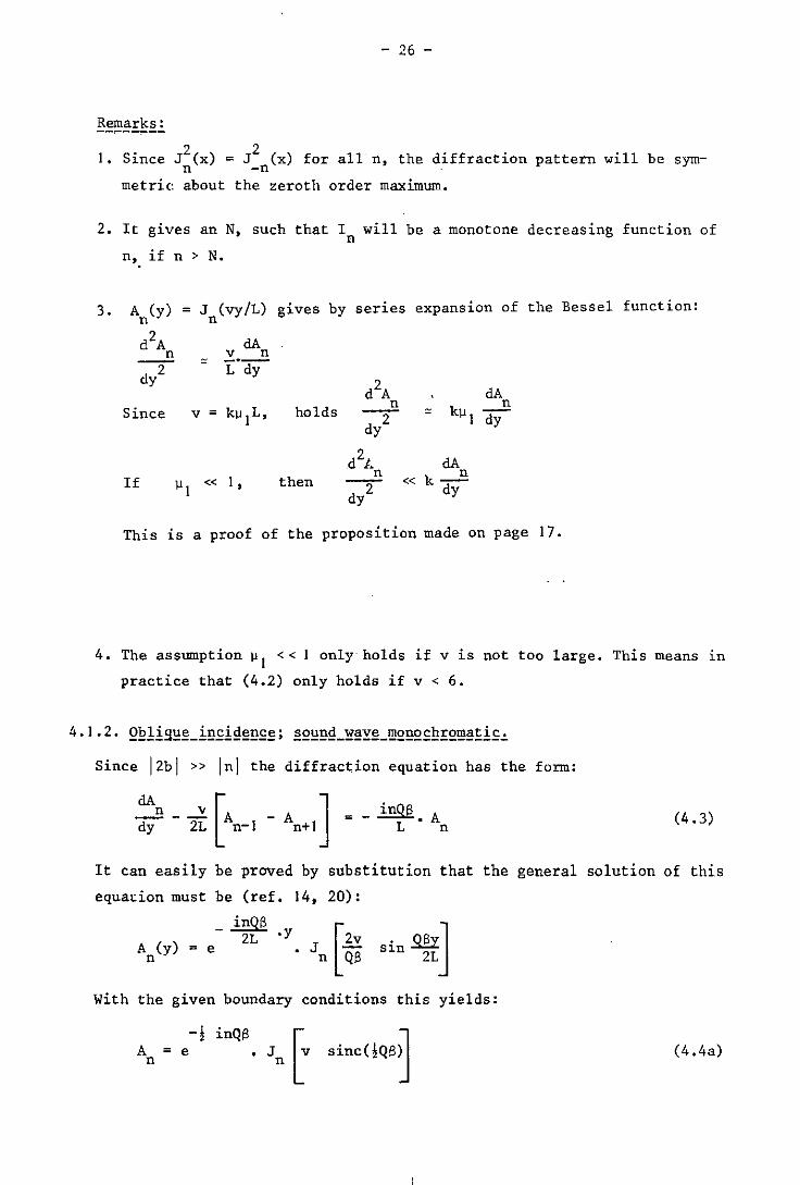
4. No diffraction will take place, if !QS = + n.
For in that case:
J v sinc<!QS) = J (v sinc n) = 0, if nt O. n n
Now if !QS = + n it can also be written:
Fig. 4.1.
_ .::!W. _ - 2n sin:! - bL - + bL
A a =--r. ~ tan",
- - -- - ~=-=:...:::..=::.=>it;~ light
L ._---- - - ----
sound beam y=O y=L
- 28 -
This means (fig. 4.1) that diffraction will just disappear, if the
light wave is incident at such an angle that it will shift exactly
one sounu wavelength in the z-direction during its passage through
the sound field.
5. The true meaning of the weight factor jQS will be made clear in
Cliapter 5.
4.1.3. ~~!E~B9iE~!~!_iBEi9~BE~: §g~B9_~~Y~_E~!ig9iEL_~~~_Bg~_~g~gE~!g~~~iE'
The diffraction equation omitting the phase terms e io has the following
form (ref. 35):
- '\ v A l L s· n+j o (4.5 a)
The solutions of this equation can be found indirectly in the following
way:
The angle of incidence of the light on the sound is zero. However, when
the light wave emerges from the sound field it propagates into all direc
tions, according to Huygens' principle. We shall consider only that part
of the light wave that progresses at an angle e with respect to its or1-
ginal direction.
In appendix A we have derived a relationship between the amplitude of a
light wave as a function of e:(A'(e» and this same amplitude as a function
of the position on the line y = L:(A(z»:
Jm -inz
A'(n) = A(z).e dz in which n = k sine
The refractive index of the medium varies periodically in the z-direction
(~(z) = ~o + ~I(z~. As a result, the phase angle of the light wave at
the exit plane of the sound field (y=L) will also vary periodically. This
phase angle can be written as: ~ = kL~(z) = kL~o + kL~I(Z)'
The amplitude at the exit plane will now be:
A(z) = C.e -ikL~ 1 (z) -ikL~O
C = e this constant as not
being relevant will be
neglected henceforth.
(4.5b)
- 29 -
Because of the periodicity of A(z), the amplitude A'(n) (its Fourier trans
form) will be a discrete function, as it is non-zero only for certain eigen
values of n. To find these eigen-values (2.6) is used:
n = k sine ke nbk nb* ~ = kilo = n. integer
b = bIll o
If the sound wave is sinusoidal and its wave number equals b, then:
-ikLIlI·sin(bz) -ivl·sin(bz) = e = e
From (4.2a) we get:
A'(n) = A * = J (v ) I nb n I
If the wave number of the sound wave equals mb ( m integer), then
obviously:
A2(z) -iv 2. sin(mbz)
= e
and
Ai(n) = A *' = J (v ) nmb n 2
(4.6)
(4.7)
When combining these two waves to form a new one consisting of a fund amenth tal tone and its m harmonic, the following expression will hold for
this wave:
A(z) =e -i(v I' sin(bz) + v2·sin(mbz»
= AI (z) .A2 (z)
A'(n) and A(z) form a Fourier transform pair, so that
Substitution of (4.6) and (4.7) and evaluation of the convolution integral
produces the following amplitudes of the diffraction maxima:
- 30 -
If the sound wave contains an infinite number of harmonics:
Substitution of (4.6) and (4.7) will yield:
An = l: l: l: ..... I n- 2k -3k ••• (vI) ·Jk (v2) ·Jk (v3)······· (4.8) k2 ' k3 ' k 4' •• =-00 2 3 2 3
This is the solution of Eq. (4.5) with the given boundary conditions.
I. In the expression
refractive index
v s due
= kLllls llls represents the disturbance In the
to the 8th harmonic of the sound wave.
2. It is impossible to find an·expression for I , since Eq. (4.8) is too n
complicated.
3. Murty (ref. 22) has shown that the diffraction pattern will be synnnetric
about the zeroth order, if the sound wave only contains odd harmonics.
If there are also even harmonics present, then the diffraction pattern
may show an assymetric shape.
The proof to Murty's proposition is very complicated and will conse
quently not be treated here. On the basis of his proposition it may
be stated that (ref. 17, 31):
a diffraation pattern aan only be assymetria about the zeroth
order. if the sound wave aontains even har-monias.
This can also be formulated more clearly:
a diffraation pattern wiZZ be assymetria. if and onZy if the
sound wave itseZf is assymetria (fig. 4.2).
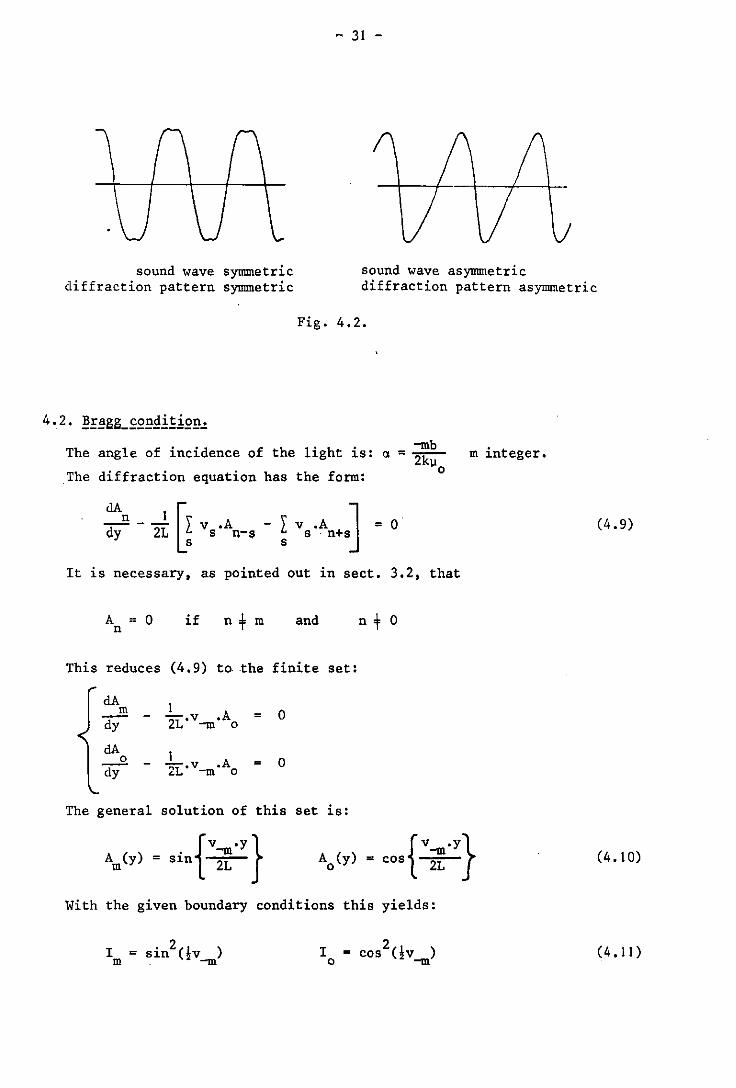
~ 31 -
sound wave symmetric diffraction pattern symmetric
sound wave asymmetric diffraction pattern asymmetric
Fig. 4.2.
The angle of incidence of the light is: -mb (l =-
2kll o The diffraction equation has the form:
It is necessary, as pointed out in sect. 3.2, that
A = 0 if n+m and n + 0 n
This reduces (4.9) to the finite set:
dA 1 m .A 0 - TL·v-m = dy 0
dA 1 --2. - TL_v-m .A = 0 dy 0
The general solution of this set is:
With the given boundary conditions this yields:
2 I = cos Ov ) o -m
m integer.
(4.9)
(4.10)
(4.11)
- 32 -
It can be seen that the light only appears in one or two diffraction orders
in the case of the sound wave being monochromatic.
I. The angle between the incident light beam and the y-axis is mb
a.= 2k 110
The angle between the emerging light beam and the y-axis is
a ' = a-a (fig. 4.3)
mb a ' = kl1
o
mb - 2kl1
o = a ( a
It can be seen that both angles are equal. This means that, as far as
these angles are concerned, Bragg diffraction can be considered as a
mere reflection of the light on the sound wave-fronts.
, a I -L----">~__Ifl-l\ ---
< >
------',~
sound field
Fig. 4.3.
2. Q has to be infinitely large in order to obtain a pure Bragg diffrac
tion. If Q is finite, then only some kind of a transitional state
between Raman-Nath and Bragg diffraction will be obtained. In that case
part of the light will be found in those orders, that border directly
on the .zeroth and the mth order. According to Phariseau's computations
(ref. 30) more than 95% of the light will be found in either the zeroth th or the m order, when Q > 10 (instead of 100% in the case of pure
Bragg diffraction).
4.3. ~~~!Y.!
One may distinguish two forms of light diffraction by ultrasound:
Raman-Nath diffraction occurring when Q = 0
and Bragg diffraction occurring when Q = 00.
- 33 -
But, since Q has a finite value, some intermediate. form will always be
met with in practice.
The following characteristics may be noted:
1. In the case of a monochromatic sound wave:
The Raman-Nath diffraction pattern is symmetric. It contains an infinite
number of orders. However, the light intensity of the orders decreases
very rapidly when the order number increases.
The Bragg diffraction pattern is extremely assymetric:
except for the zeroth order maximum, only one other maximum is present.
This maximum is found at the same place, where it would be found, if
the sound wave had been replaced by'a mirror.
2. In the case of a sound wave being periodic, but not monochromatic:
The diffraction pattern is the convolution product of the diffraction
patterns that would otherwise have been generated by each of the
sound-harmonics separately.
- 34 -
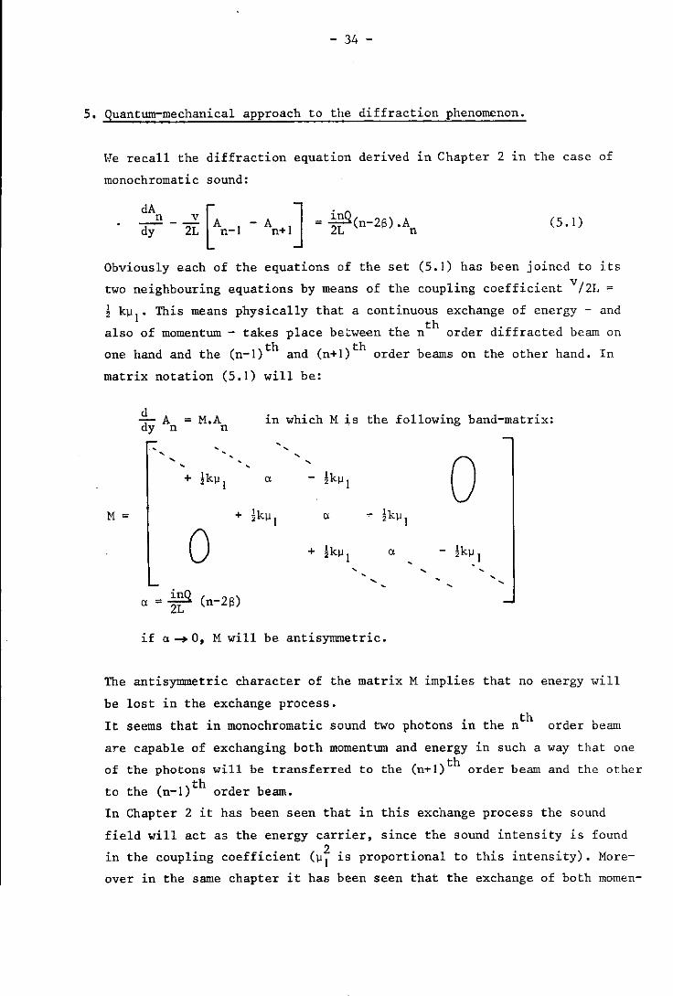
5. Quantum-mechanical approach to the diffraction phenomenon.
~Ie recall the diffraction equation derived in Chapter 2 in the case of
monochromatic sound:
n v dA [ dy - 2L An_I - ] -~ An+1 - 2L (n-2S).An
(5. I)
Obviously each of the equations of the set (5.1) has been joined to its
two neighbouring equations by means of the coupling coefficient v/ 2L = ! k~I' This means physically that a continuous exchange of energy - and
also of momentum - takes place between the nth order diffracted beam on
one hand and the (n_l)th and (n+l)th order beams on the other hand. In
matrix notation (5.1) will be:
i... A = M.A dy n n
in which M is the following band-matrix:
M = +
0 _ inQ
Cl - 2L (n-2S)
"
, ,
lk~1
+
" - lk~ 2 I
!k~1 " , ,
if ,,-+ 0, M will be antisymmetric.
o , ,
The antisymmetric character of the matrix M implies that no energy will
be lost in the exchange process. th
It seems that in monochromatic sound two photons in the n order beam
are capable of exchanging both momentum and energy in such a way that one th of the photons will be transferred to the (nTI) order beam and the other
to the (n_l)th order beam.
In Chapter 2 it has been seen that in this exchange process the sound
field will act as the energy carrier, since the sound intensity is found 2 in the coupling coefficient (~I is proportional to this intensity). More-
over in the same chapter it has been seen that the exchange of both momen-
- 35 -
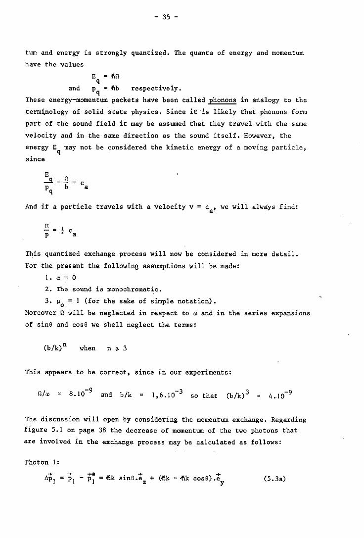
t~ and energy is strongly quantized. The quanta of energy and momentum
have the values
E =-fin q
and p = -fib respectively. q
These energy-momentum packets have been called phonons in analogy to the
term~nology of solid state physics. Since it ·is likely that phonons form
part of the sound field it may be assumed that they travel with the same
velocity and in the same direction as the sound itself. However, the
energy E may not be considered the kinetic energy of a moving particle, q . since
And if a particle travels with a velocity v = ca ' we will always find:
This quantized exchange process will now be considered in more detail.
For the present the following assumptions will be made:
1.,,=0
2. The sound is monochromatic.
3. ~ = 1 (for the sake of simple notation). o
Moreover n will be neglected in respect to wand in the series expansions
of sinS and cose we shall neglect the terms:
when n ~ 3
This appears to be correct, since in our experiments:
and b/k ~ -3 1,6.10 so that -9 4.10
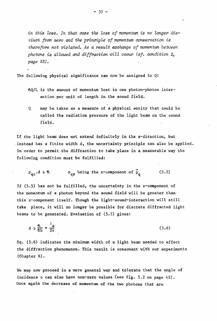
The discussion will open by considering the momentum exchange. Regarding
figure 5.1 on page 38 the decrease of momentum of the two photons that
are involved in the exchange process may be calculated as follows:
Photon 1:
(S.3a)
- .36 -
Photon 2:
• + + ~ - ~k S1nS.e + (~k - ~k cosS).e z y
(5.3b)
The z-components of these momentum alterations can be explained by stating
that a momentum quantum running in the positive z-direction has been
transferred from photon to photon 2:
However, the y-components do entail a certain loss of momentum 0 , since P
these components have the same sign in both the equations (5.3). We find
that
o p
2(iik - iik cosS) (5.4)
At first sight this loss seems to violate the principle of momentum con
servation. However, we have some information on the y-coordinate (Yo) of
the positions of the photons at the moment that the exchange of momentum
takes place, namely that 0 < Yo < L. This means that the position of the
exchange is subject to an uncertainty 6y ~ L.
According to Heisenberg's uncertainty principle an uncertainty must now
also be found + + ..
and P2 - P2 •
r.6y ~ ii
in the y-components of the momentum
Let this uncertainty be r, then:
or r ii >/ L
1£0 p
< r, <I is no longer distinct from zero. p
<I will p
certainly be smaller than r, if
o p
ii <-L
This gives:
ii <
L
< I and using (2.18): Q < I
From this an important conclusion can be drawn:
. -+ -+* alterat10ns PI - PI
If Q < I, the loss of momentum of a photon travelling through
the sound field will definitely be smaller than the uncertainty
- 37 -
in this loss. In that aase the loss of momentum is no longer dis
tin at from zero and the prinaiple of momentum aonservation is
therefore not violated. As a result exahange of momentum between
photons is allowed and diffraation wilt oaaur (af. aondition 2,
page 22).
The following physical significance can now be assigned to Q:
~Q/L is the amount of momentum lost in one photon-photon inter
action per unit of length in the sound field.
Q may be taken as a measure of a physical entity that could be
called the radiation pressure of the light beam on the sound
field.
If the light beam does not extend infinitely in the z-direction, but
instead has a finite width d, the uncertainty principle can also be applied.
In order to permit the diffraction to take place in a measurable way the
following condition must be fulfilled:
p .d ~ ~ qz . +
p be1ng the z-component of p qz q (5.5)
If (5.5) has not be fulfilled, the uncertainty in the z-component of
the momentum of a photon beyond the sound field will be greater than
this z-component itself. Though the light-sound-interaction will still
take place, it will no longer be possible for discrete diffracted light
beams to be generated. Evaluation of (5.5) gives:
(5.6)
Eq. (5.6) indicates the minimum width of a light beam needed to effect
the diffraction phenomenon. This result is consonant with our experiments
(Chapter 6).
We may now proceed in a more general way and tolerate that the angle of
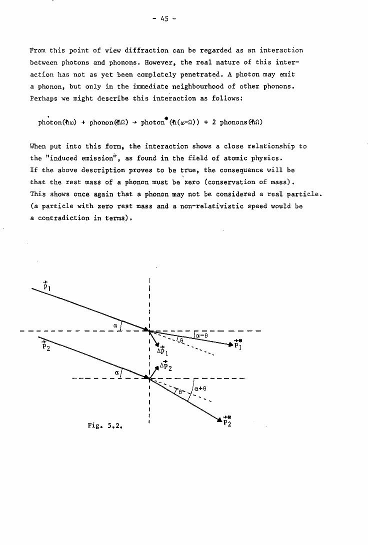
incidence ~ can also have non-zero values (see fig. 5.2 on page 45).
Once again the decrease of momentum of the two photons that are
- 38 -
~ = -fl(w-Il)/C = uk
photon 1 .<~ t'l b S = k
b sinS = k +
~P~I~=~ft~k~------~-----h-b~·j~;P;-
Pq
cosS = 1 photon 2 °p2
-'------~.~---p=-!lk ·S 2 * P2 = ft(w+Il)/c = uk
Fig. 5. 1 •
involved in the exchange process will be calculated: Photon I:
= -flk sina - -flk sin(a-e) = 2flk cosH2a-e) .sinje
IIPly = -Ilk cosa - -Ilk cos(a-e) = 2flk sinH2a-e) .sinle
Photon 2! (5.7)
IIP2z= -fik sina - -fik sin(a+e) = -2flk cosH2a-e) .sinle
1I~2y = -Ilk cos a - -Ilk cos(a+e) = -2fik sinj(2a+e).sinle
Using 2k sinje = b (5.7) becomes:
- 39 -
lip = Iz
<!\.b cos!(2a-e)
llPly = <!\.b sin!(2a-S) (5.8)
llP2z - <!\.b cos!(2a+S)
llP2y = - <!\.b sin!(2a+S)
It is now possible to distinguish the following cases:
l.a=O.
This case has already been discussed in the foregoing. It represents . ~
the Raman-Nath diffraction. Photon I em1ts a momentum quantum p = , q ~
<!\.b. e • Photon z
2 admits this quantum. If Q < I, the uncertainty prin-
cip1e permits the ensuing deviation from the law of momentum conser-
vat ion.
2.2a=e.
This represents the Bragg condition, if Q > I. Eq. (5.8) changes into:
llPlz
llPly
llPZz
llP2y
= fib
= 0
= - <!\.b cose = - -I1b +-I1b3/k2
= -./\b sine = - -fib 2 /k
(5.9)
This set of equations shows that photon I can emit a momentum quantum ~ ~
p = -flb.e , without losses and independent of the value of Q. Photon 2, q z
however, cannot admit such a quantum without at the same time losing
an amount of momentum t : p
t p
<!\.b 2 ~ = - --.e
k y
If Q > I, then this loss is not consistent with the momentum conserva
tion principle. Hence it follows that:
Photons incident at the angle a = !e (Bragg angle) are capable of emit-
ting a momentum quantum (phonon) but incapable of admitting one; on
the other hand, photons incident at the angle a = - Is are capable of
admitting a phonon but incapable of emitting one.
This is in accordance with the experiment. In Bragg diffraction only
the _I th order maximum will be found, when a = Is, and only the +Ith
3.
- 40 -
order maximum, when ex = -!e. From this an important conclusion can be dra~~:
The interactions dealt with here are in fact photon-phonon interac
tions. The emission and the admission of phonons by a photon are
two processes that may take place independently of each other. Raman
Nath diffraction only seems to be a direct photon-photon interaction.
That is because the likelihood of a phonon being emitted equals the
likelihood of it being admitted. And that is why on an average these
processes occur equally frequent.
2cx » e. According to (2.19): 2ex = 2 sina =
2b S 26S. -k = -
Thus 2ex » e, if ISI»lnl > 1 , . In Chapter 3 this condition has been called "oblique incidence". Eq.
(5.8) changes into:
bPlz = 11b COSC1
}-+lrPll = -i1b bP1y
= 11b sina (5.10)
bPZz = - fib coso: }~IEt21 = 11b bP2y
= - 11b sina
This set of equations shows that in this case a phonon can be either
emitted or admitted by a photon with neither process giving rise to
any loss of momentum, however large Q may be. But (5.10) also shows
that the phonons involved are all travelling at an angle ex with res
pect to the direction of propagation of the sound, i.e. the z-axis.
The likelihood of a phonon travelling at such an angle ex is determined
by the amplitude of the sound wave as expressed as a function of ex.
In Chapter 4 we have called this function A'(n), wherein n = n(ex).
In that chapter we have also seen that A'(n) is the Fourier transform
of A(Y), the amplitude of the sound wave as expressed as a function
of the position y in a direction perpendicular to the z-axis. This
theorem has been evaluated in Appendix A. If the results of this eva
luation are applied to the sound beam in question, we will find:
00
A'(a) = I A(y).eibyex.dy
-00
- 41 -
For the sound amplitude A(y) holds:
A(,) - { :
if Iyl < L
if Iyl > L
Hence:
t A' (a) = eibya.dy = L sine <! bLa)
-!L
Since Q b2L and S k sina k =-- = -j) " -j) a
k
also ~bLa = - IQS
and A'(a) = L sinc(!QS) (5.11)
As stated previously A'(a) is a measure of the likelihood of finding a
phonon travelling at an angle a with the z-axis. And of course it is
also a measure of the likelihood of a photon meeting such a phonon and
consequently being diffracted. Therefore in computing the total amount
of photons having been diffracted, A'(a) will act as a weight factor to
be assigned to the coupling coefficient v/2L.
This weight factor can be compared to the weight factor sinc(!QS) that
had been assigned to the coupling coefficient v in Eq. (4.4) on wave
analytical grounds. In this case the similarity between both factors
is striking.
1. If the sound wave is periodic, but not monochromatic, the diffraction
phenomenon is described by Eq. (2.20). From this equation it may be
concluded that here the interaction of the nth order beam is not res
tricted to the neighbouring beams only, but also takes place with the
(n+s)th and the (n_s)th order beam, if the sth harmonic is present
in the sound wave.
From a quantum-mechanical point of view this means that in the sound
field phonons must be present, whose energy and momentum are respec
tively:
E = 11s11 q
P = 11sb q
- 42 -
s being a natural number.
Photon-phonon interactions may also take place with these phonons.
Phonons are energy quanta. Therefore the phonon densities of the
different kinds of phonons in the sound field will be determined by
the relative intensities of the harmonics that they represent.
The likelihood of a photon interacting with one of these different
kinds of phonons p,esent in the sound field will be proportional to
the density of this particular kind of phonon: the different kinds of
phonons are independent of one anot~er in regard to the diffraction
process.
2. Up to this point our discussion has only dealt with the momentum ex
change. A discussion about the energy exchange is not relevant: for
neither will additional insight be' gained nor additional problems loe
found. The photon energy will always change an integer multiple of
1111, and since. energy is a scalar quantity no restrictions will be im
posed on the diffraction process. The constraints that have been found
in the foregoing are caused by the, exchange of momentum only.
3. Some remarks can be made on the angular momentum.
The value of the intrinsic angular. momentum of a photon is~, its
direction is determined by the direction of polarization of its light
wave.
Our experiments have lead to the following result:
if a linear polarized light beam passes through a beam of ultrasonic
waves, the light in the diffracted beams emerging from the sound is
also linear polarized. And the direction of polarization does not appear
to be altered by the diffraction process.
Bbcause of this experimental fact we are led to conclude that the in
trinsic angular momentum of a phonon, s , (phonon spin) will have to q
be zero.
+ s
q
Naturally this conclusion is only valid in case of longitudinal sound
waves.
- 43 -
4. The quantum-mechanical considerations dealt with in this chapter pro
duce an unexpected result:
there appears to be still another kind of diffraction not yet mentioned.
This particular kind of diffraction occurs, if the light beam is heading
in the same direction as the sound beam. In that case the photon mo
ment1IDl is:
This implies that exchange of momentum between light and sound will
always be possible without losses and independent of the value of Q. As a result of this exchange the photort momentum will change into:
+ + + = PI - P = ~(k-b)e q z phonon emission
+ ... P2
+ + + = P2 - P =~(k+b)e q z phonon admission
,The direction of the photon will remain unaltered during this exchange
as can be seen from the above equations. Hence the only measurable effect
of the diffraction will be due to energy exchanges: each of the spec
tral lines of the incident light beam will be split up into a series
of equidistant lines. The frequencies of these equidistant lines will
be:
w = w + nn n
n integer
n -8 Though /w ~ 10 • the splitting of the spectral line will just be
measurable when the most sensitive spectral analysers available at
this moment are used. A laser has to be used as a light source in this
experiment, since in the frequency domain the spectral line width of
a laser ,beam will be extremely small compared to n. Though this kind of diffraction can immediately be understood when
using quantum-mechanical concepts, it is not possible to understand
it from a'wave-analytical point of view. Therefore it must be considered
to be a direct result of the quasi-particle character of the sound wave.
5. At this point it is also possible to understand, why the length of the
integration path, L, will always be found as a coefficient in the
diffraction equation.
- 44 -
In the foregoing it has been made clear that there must be an un
certainty in the y-coordinate of the position of the momentum ex-
change between photons and phonons. Otherwise the direction of the dif
fracted photon would be undetermined. Consequently, though it will
be possible to measure the mere fact that the photon momentum has
changed, it will be fundamentally impossible to measure where in the
sound beam the alteration has taken place. The momentum of the photon can
be measured before and after its passage through the sound beam, but
not halfway through.
This means mathematically spoken that the diffraction equation can
not be integrated over an arbitrary ,path length ~y. Only the solution
found if ~y = L has any significance. Consequently the diffraction
equation can only be meaningful, if the integration path is known be
forehand. And this results in the occurrence of L as a coefficient
in this equation.
When reviewing the quantum-mechanical considerations of this chapter
. we may conclude that this way of approaching the diffraction process
has lead to exactly the same kinds of diffraction phenomena as well as
to exactly the same conditions as the wave-analytical approach of the
previous chapters has done. Moreover this quantum-mechanical description
predicts yet another kind of diffraction that consists of a splitting
of the spectral lines of the light wave. And finally it provides us
with an additional insight into the real physical significance of the
parameters of the diffraction equation.
The remarkable correspondence between the results of the quantum
mechanical and the wave-analytical theories strongly supports the
idea that the conception of particle-wave duality may also be extended
to sound waves. Apparently sound can be regarded as a wave and equally
well·be considered a stream of quasi-particles, phonons.
To the physical properties of these phonons the following quantities
can be assigned:
energy:
momentlJlIl:
angular momentum:
velocity:
E =.flO q p =.ftb
q ; = 0 (longitudinal waves only)
q Vq = ca
- 45 -
From this point of view diffraction can be regarded as an interaction
between photons and phonons. However, the real nature of this inter
action has not as yet been completely penetrated. A photon may emit
a phonon, but only in the immediate neighbourhood of other phonons.
Perhaps we might describe this interaction as follows:
• • photon(~w) + phonon(~n) + photon (~(w-n» + 2 phonons(~n)
When put into this form, the interaction shows a close relationRhip to
the "induced emission", as found in the field of atomic physics.
If the above description proves to be true, the consequence will be
that the rest masS of a phonon must be zero (conservation of mass).
This shows once again that a phonon may not be considered a real particle.
(a particle with zero rest mass and a non-relativistic speed would be
a contradiction in terms).
Fig. 5.2. ...... P2
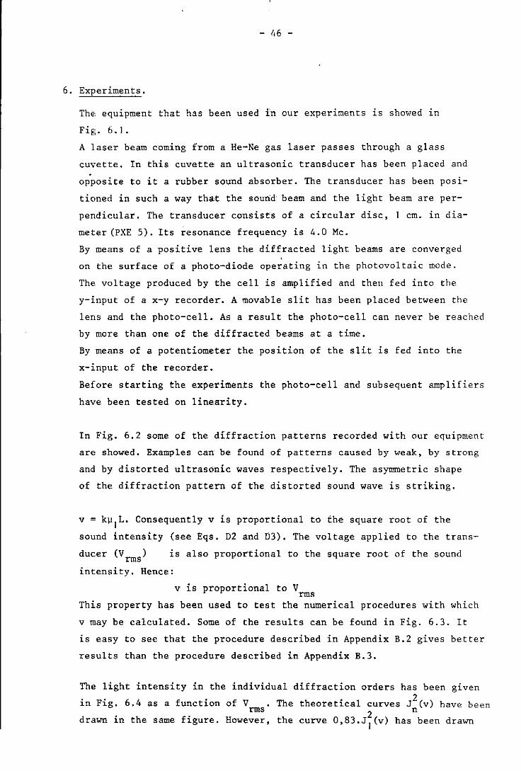
6. Experiments.
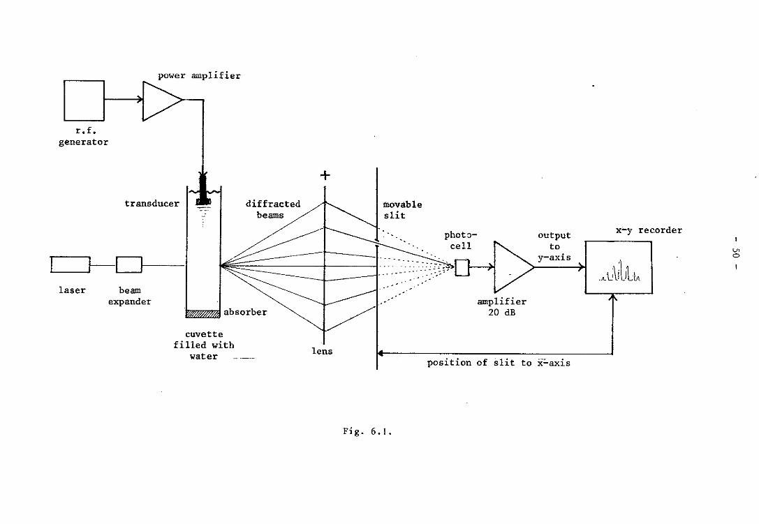
ThE, equipment that has been used in our experiments is shOl.ed in
Fig.6.1.
A laser beam coming from a He-Ne gas laser passes through a glass
cuvette. In this cuvette an ultrasonic transducer has been placed and
opposite to it a rubber sound absorber. The transducer has been posi
tioned in such a way that the sourid beam and the light beam are per
pendicular. The transducer consists of a circular disc, I cm. in dia
meter (PXE 5). Its resonance frequency is 4.0 Mc.
By means of a positive lens the diffracted light beams are converged
on the surface of a photo-diode operating in the photovoltaic mode.
The voltage produced by the cell is amplified and then fed into the
y-input ofax-y recorder. A movable slit has been placed between the
lens and the photo-cell. As a result the photo-cell can never be reached
by more than one of the diffracted beams at a time.
By means of a potentiometer the position of the slit is fed into the
x-input of the recorder.
Before starting the experiments the photo-cell and subsequent amplifiers
have been tested on linearity.
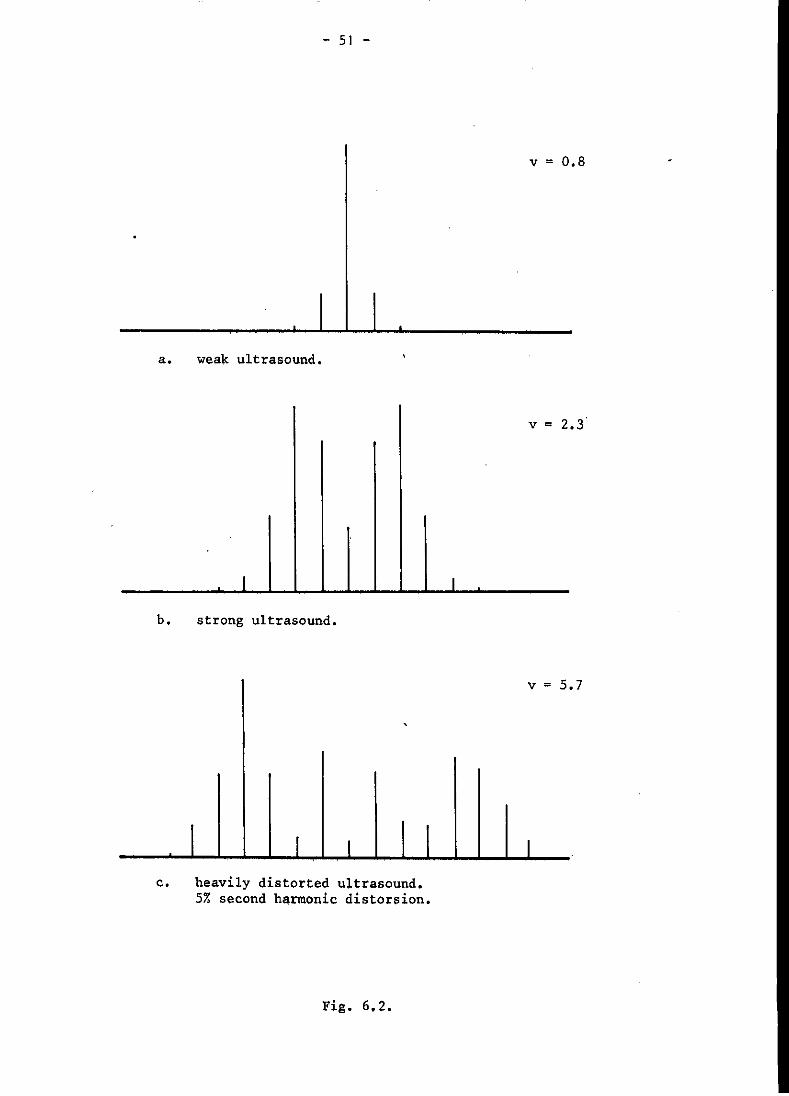
In Fig. 6.2 some of the diffraction patterns recorded with our equipment
are showed. Examples can be found of patterns caused by weak, by strong
and by distorted ultrasonic waves respectively. The asymmetric shape
of the diffraction pattern of the distorted sound wave is striking.
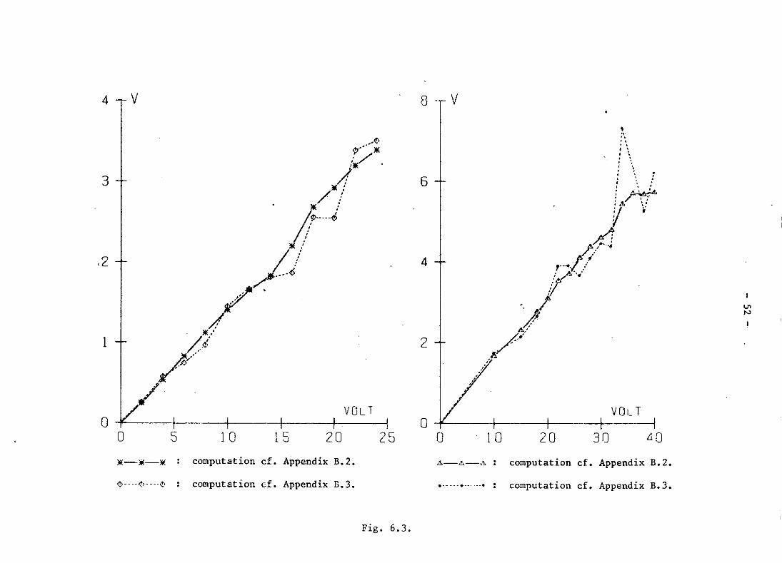
v = k~IL. Consequently v is proportional to the square root of the
sound intensity (see Eqs. D2 and D3). The voltage applied to the trans-
ducer (V rms) is also proportional to the square root of the sound
intensity. Hence:
v is proportional to V rms
This property has been used to test the numerical procedures with which
v may be calculated. Some of the results can be found in Fig. 6.3. It
is easy to see that the procedure described in Appendix B.2 gives better
results than the procedure described in Appendix B.3.
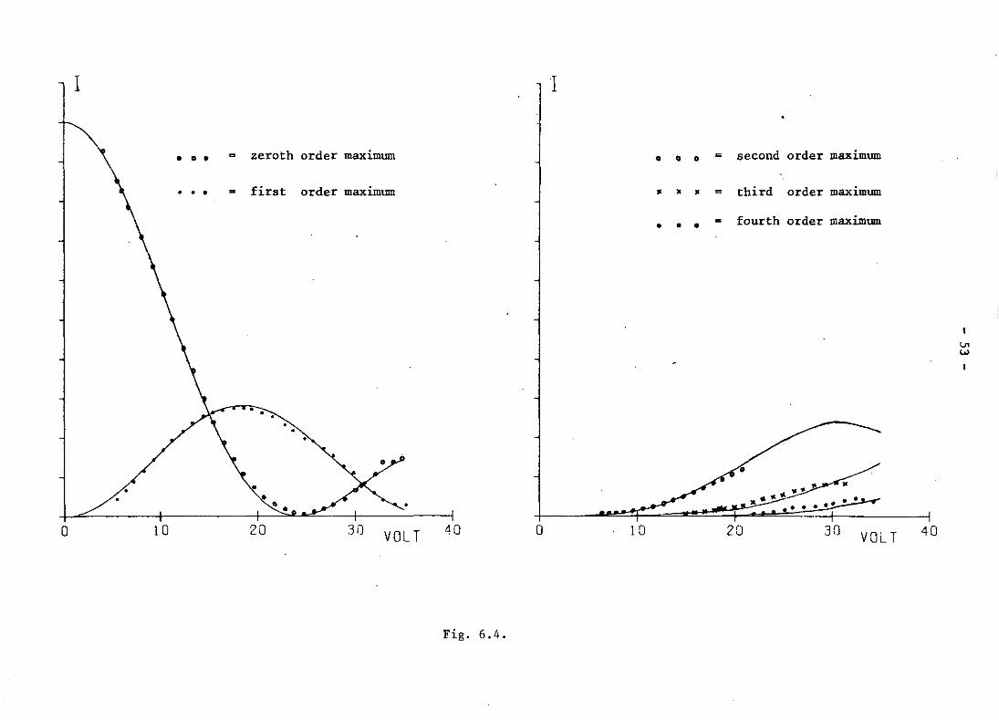
The light intensity in the individual diffraction orders has been given
in Fig. 6.4 as a function of V The theoretical curves J 2 (v) have been rms 2 n
drawn in the same figure. However, the curve 0,83.JI(v) has been drawn
- 47 -
iutiL",ad of J~(v) in order to account for a loss of light in the first
order diffracted beam due to improper alignment of the slit during the
experiment.
The recording of light intensities in the case of the voltage excee
ding 35 Volt appeared to be impossible. For in that case cross-talk
between the r.f. generator and the photocell disturbed the recordings.
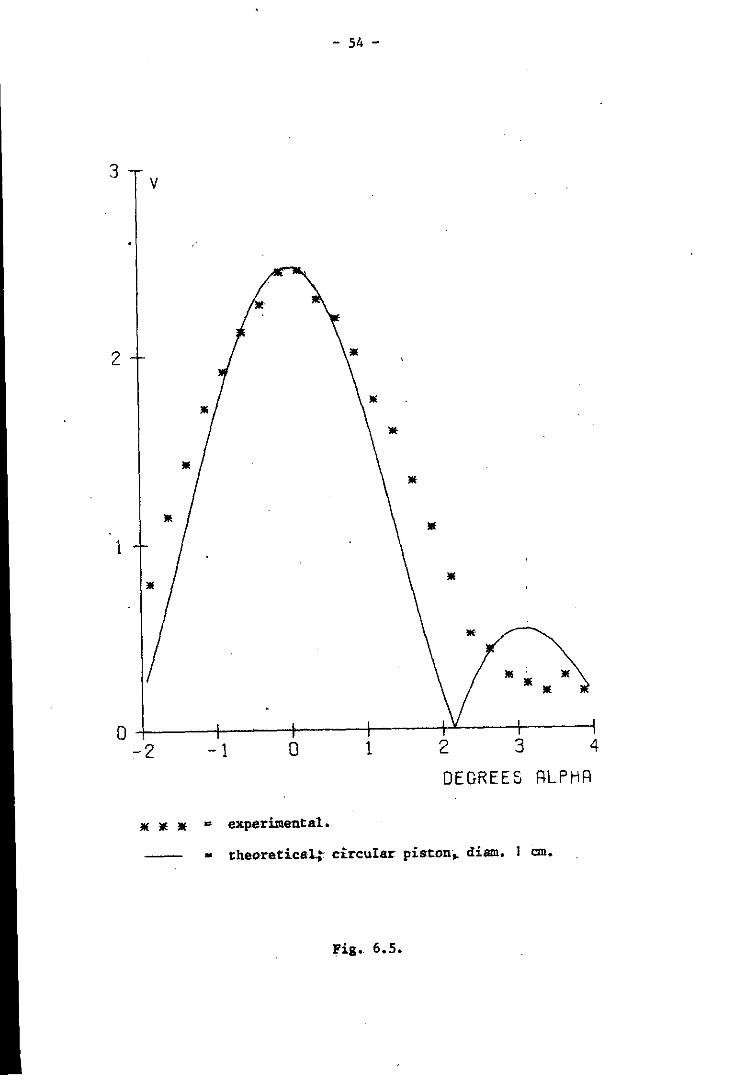
In Eqs. (4.4) and (5.11) a weight factor can be found that has to be
assigned to v in the case of an oblique incidence. This weight factor
represents the radiation pattern of the transducer and therefore it
will have the shape of a sine-function, if the transducer vibrates purely
as a circular piston.
We have tested this assumption experimentally. To this purpose v has
been measured while gradually tilting the transducer in steps of a
quarter of a degree.
The result of this experiment has been given in Fig. 6.5 together with
the theoretical result:
v = v .sinc(!QS) o
From Fig. 6.5 it may be concluded that:
1. the experimental results do n'ot fit with the theoretical curve. In
fact they do not fit with any sinc-function at all. Apparently the
transducer in our experiment does not vibrate as a circular piston.
2. the experimental curve is broader than the theoretical one. This
means that the effective diameter of the transducer is smaller than
its physical diameter.
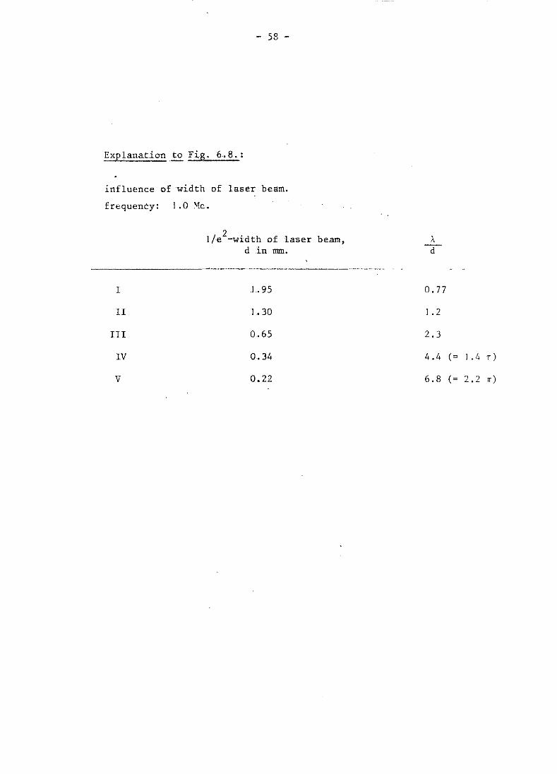
Eq. (5.5) has also been tested experimentally. In this experiment a
transducer has been used that worked at a frequency of 1.0 Mc. Light
beams of different widths have been obtained by varying the properties
of the beam expander.
It can be seen from Fig. 6.8 that the agreement between theory and
experiment is excellent. Diffraction just disappears when d < A/2n.
This good agreement between theory and experiment is remarkable, since
there is some kind of vagueness in Heisenberg's uncertainty relation due
to the fact that the right hand side of his relation ( =~) only gives
an order of magnitude of the uncertainty dependent on how this uncertain
ty is defined. It is therefore not to be expected that experiments
based on this uncertainty relation will fit to theory within more than
about a factor two.
-' 48 -
In the Figs. 6.6 and 6.7 the results have been given from two experi
ments, in which the intensity distribution has been measured in a
sound field by stepwise scanning it with a laser beam.
The diffraction patterns occurring in each step of this scanning pro
cedure have been recorded on the x-y recorder. From each of these
recordings the value of v has been calculated using the numerical pro
cedure described in Appendix B2.
In the left-hand graphs of the two figures 6.6 and 6.7 the values of v
thus obtained have.been plotted against the subsequent positions of ,
the laser beam in the sound field expressed in the:x-coordinate. As
a result this left-hand graph rep~es.nts a series of points lying on
the curve v = v(x).
From the curve v = v(x) it is possible to calculate the radial distri
bution of the absolute sound intensity in the sound beam, t = I(r), r
being the distance to the beam axis. In this calculation the assumption
has to be made that the sound beam is cylindricall~ symmetric. The
details of this calculation have been explained in 'the Appendices C and
D.
In the right-hand graphs of the two figures 6.6 anq 6.7 the values of
I = I(r) thus obtained have been plotted against r. In each experiment
the total power in the sound beam has also been calculated; this has
been done by numerical integration of the right-hand graphs.
In Fig. 6.6 the distance in the z-direction between the transducer and
the measuring plane has been 50 mm. (far-field). In Fig. 6.7 this dis
tance has been 7 mm. (near-field). It is clearly visible that at the
near-field distance the maximum value of the acoustic intensity is
reached beside the beam axis, instead of on the beam axis, as is the
case at the far-field distance.
The voltage applied to the transducer was much higher in the case of
Fig. 6.} than it was in the case of Fig. 6.6.
In both figures a slight increase of intensity may be seen at the edge
of the beam in the radial distribution graph. This is an artifact due
to the truncation of the tails of the function v = v(x).
We have also tried to demonstrate the diffraction phenomenon described
in Chapter 5, remark 4. Unfortunately, we have not succeeded in obtaining
a spectral analyser having a sufficiently high resolving power (10 Mc
in the frequency domain).
- 49 -
However, some observations have been made on the speckle patterns
caused by the laser light before and after its passage through the
sound field. This observations have given strong evidence that the
light beam is indeed frequency shifted by the sound, even in the case
that the light and the sound beam run in parallel directions.
In the future further efforts will be made to measure this frequency
shift quantitatively.
r.f. generator
laser
power amplifier
transducer
beam expander
diffracted beams
~1IiI:i!~ absorber
cuvette filled with
water
+
lens
movable slit
- .. -.
Fig. 6. I .
phot:>cell
amplifier 20 dB
output to
y-axis
position of slit to x~axis
x-y recorder
<.n o
- 51 -
a. wea~ ultrasound.
I
h. strong ultrasound.
,
I I I I c. heavily distorted ultrasound.
5% second harmonic distorsion.
Fig. 6.2.
v = 0.8
v = 2.3'
I
v = 5 .7
I
4
3
1
0
v
p ...• -: :/ 'lili
/I lIIi :
/.: )I[ ; !1> ..... $
/J /'
0
liE:
/.i it/
y" /
5 I
1 0
Ji(-Ji(-Ji( computation
<1> .... <1> .... <1> computation
VOLT I
15 20 25
cf. Appendix B.2.
cf. Appendix B.3.
Fig. 6.3.
8
6
4
2
o
v • " " , , , , , \ , , , , , , : \ , ' , ,
. , '
I!.~~ ,~/ ',' / ~'
;:f.J ! ,-,........ ::
: " .... :~-
i/ -/ //
/E.
...
VOLT
o 10 20 30 LlO
&-,~-,~ computation cf. Appendix B.2.
... _ ..•... ... computation cf. Appendix B.3.
U> /'oJ
I I
••• = zeroth order maximum • • • = second order maximum
first order maximum • • • = third order maximum
• • • = fourth order maximum
•
• • •
6 • o 10 20 3i) VOLT 40 o 10 20 30 VOLT 40
Fig. 6.4.
- 54 -
3 v
2
1
o +-----+-----+-----~--~~--~----~ -2 -1 o 1 2 3 4
DEGREES RLPHR
lIE lIE lIf c experiJnental.
_ theoreticait circular pistDn. diam. I em.
Fig •. 6.5.

- 55 -
2
1
.5
v left: observed values of v.
right: intensity distribution in sounq bea~.
frequency: 4.0 M~.
distance to X-~a~: 50~.
femperat~f~: 22o
C.
1\ / \ I \
/ \ " "
. / \ / "-" " " "\ /\ .-~-.-.-",,/ "-,, " " ...............
" JI
O~--~--+---+---+---rl---rl ---Ir-~I--~I---1--~1 o 5 10 15 20 25 30 3S 40 45 50 ·55
x in mm.
Fig. 6.6.
.s
.4
I in W/cm2
total powef
tn sO\.l!ld beam:
J(i6 mW.
o 5 10 15 20 r in rom.
25

4 v
3
2
;
T ,
.5 T
left: observed values of v.
right: intensity distribution in sound bea~.
frequency: 4.0 l!c.
distance to X-tal: 7 mm.
2Z oC. temperature:
" "
.. "
"
" .. "
'"
" " .. '" " " '" " ,.
" ..
o -+1--11-' ---+!- -+1 _.+ --I,- ----+---+---- . +------+----+- .. --1
o 2 4 6 [j :0 12 )4 i6 10 20 Z?
x In TIllTl.
Fig. 6.7.
.... ... I 2
.L In w/cm
T * , 1\
< I ~
.8 iJ \ 1
I
. 6 t • \ 1
1 I • I
• II -r
0 -I- ... -l-
Cl -, L
total power
in sound beam:
383 rnW.
r in mm.
V>
"
- 58 -
Exp lanation . to Fig. 6 .. 8.:
influE!nce of width of laser beam.
frequency: I .0 'k.
1
II
III
IV
V
l/e2-width of laser beam,
d in nmI.
1.95
1.30
0 .. 65
0.34
0.22
A d
0.77
1.2
2.3
4.4
6.8
(= 1.4 TI)
(= 2.2 IT)
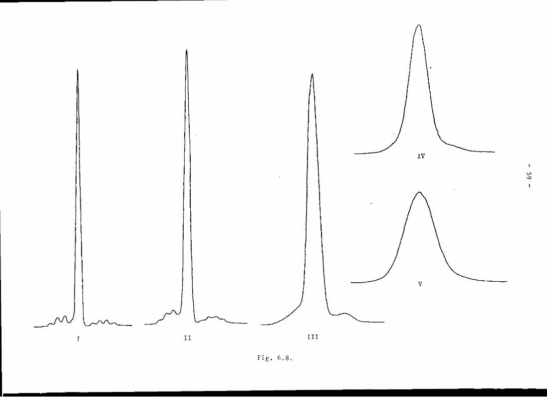

- 60 -
- 61 -
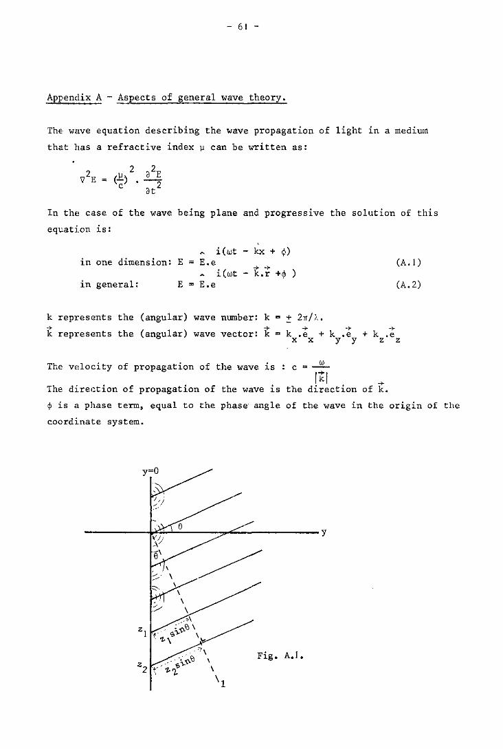
Appendix A - Aspects of general wave theory.
The wave equation describing the wave propagation of light in a medium
that has a refractive index II can be written as:
In the case of the wave being plane and progressive the solution of this
equation is:
i(wt - kx + ~) in one dimension: E = E.e (A. I)
-> -> i(wt - k.r +~ )
in general: E = E.e (A.2)
k represents the (angular) wave number: k = ! 2,,/1.. -> -> -+
k.e + k.e + k .e k represents the (angular) wave vector: k = x x y y z z
The velocity of propagation of the wave is : c = -!L It I
The direction of propagation of the wave is the direction ->
of k.
~ is a phase term, equal to the phase angle of the wave in the origin of the
coordinate system.
y=O
--------~~~--~~----------y
\
\ \ \
Fig. A.I.
- 62 -
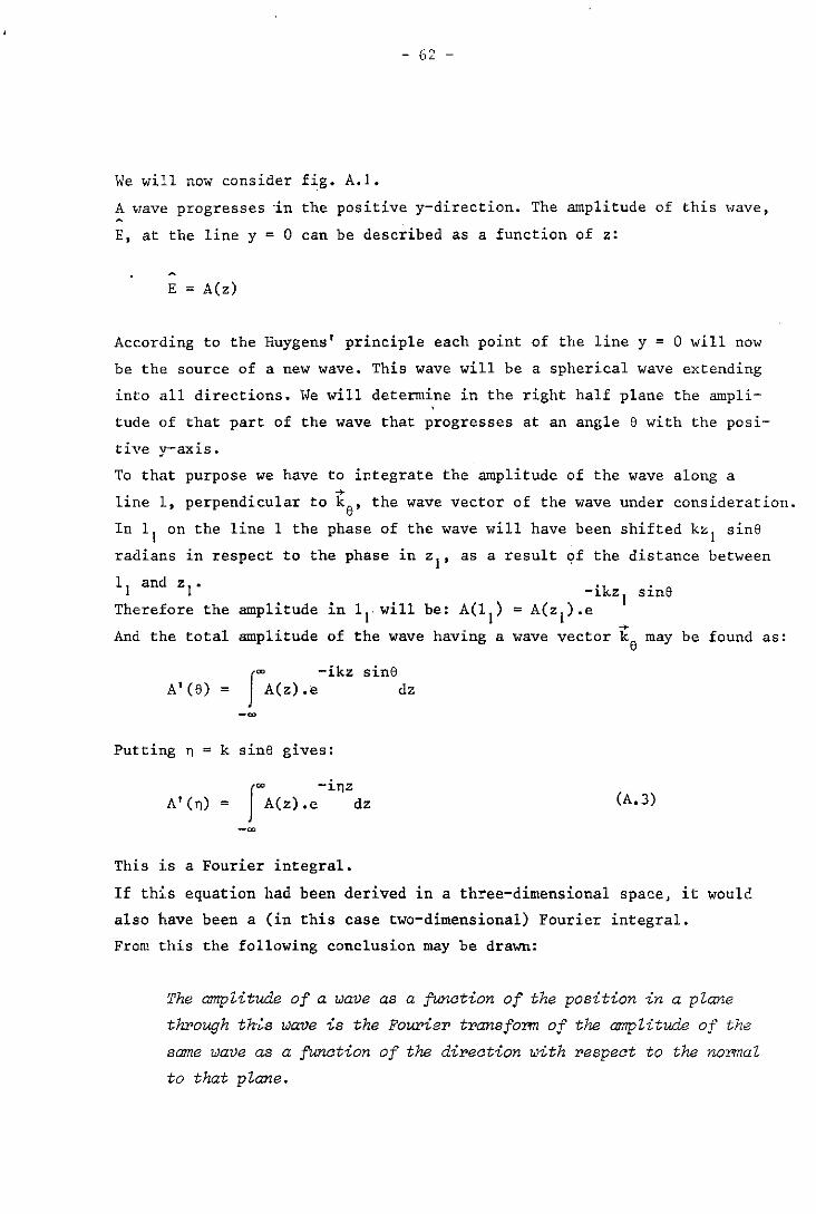
We will now consider fig. A.I.
A "ave progresses "in the positive y-direction. The amplitude of this Have,
E, at the line y = 0 can be described as a function of z:
E = A(z)
According to the Huygens' principle each point of the line y = 0 will now
be the source of a new wave. This wave will be a spherical wave extending
into all directions. We will determine in the right half plane the ampli
tude of that part of the wave that progresses at an angle e with the posi-
tive y-axis.
To that purpose we have to ir.tegrate the amplitude of the wave along a . .,.
line 1, perpend~cular to ke' the wave vector of the wave under consideration.
In lIon the line 1 the phase of the wave will have been shifted kZ I sine
radians in respect to the phase in zl' as a result of the distance between
II and zl' sine Therefore the amplitude in lrwi1l be:
. + And the total amplitude of the wave hav~ng a wave vector ke may be found as:
A' (e) = fOO -ikz A(z).e
Putting n = k sine gives:
sine dz
fOO -inz
A'(n) = A(z).e dz
This is a Fourier integral.
(A.3)
If th~.s equation had been derived in a th~ee-dimensional space, it would
also have been a (in this case two-dimensional) Fourier integral.
From this the following conclusion may be drawn:
The amplitude of a wave as a function of the position in a plane
through th"s wave is the FO!a'ier transform of the amplitude of the
same wave as a fUnction of the direction with respect to the normal
to that plane.
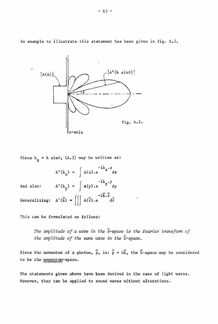
- 63 -
An ex,~ple to illustrate this statement has been given in fig. A.2.
Since k z
IA(z)1
z-axis
k sine, (A.3) may be written as:
J -ik • z
A'(k ) = A(z).e z dz z
J -ik .y
And also: A'(k) = 'A(y).e y dy y
Generalizing: A'(k) = Iff A(;).e-ik·~d~
This can be formulated as follows:
Fig. A.2.
The amplitude of a wave in the
the amplitude of the same wave
... r-space is the Fourier transfoTIn of . h'" 1-n t e k-space.
-+ -+ -+ -+ Since the momentum of a photon, p, is: p = hk, the k-space may be considered
to be the momentum-space.
The statements given above have been derived in the case of light waves.
However, they can be applied to sound waves without alterations.
- 64 -
Appendix B - Numerical methods for computing the value of v •
. Substitution of (4.5b) into (A.3) yields:
A(e) = rei(kL~I(Z) - kz sin~dZ
Let: n = k sine and fez)
then (B.I) gives:
f'" -inz
A(n) = f(z).e dz
-'"
ikL~ 1 (z) e
(B. 1 )
According to the theory of Fourier transform the following equation
will also hold:
f'" inz
fez) = C. A(n).e dn, because f'" 2 I fez) I .dz is finite.
-'" C and C' are constants.
If we put v(z) = kL~I(z) and pass over to the original variables, then
iv(z) sine e = C d(k sine) (B.2)
.l nb Eq. (2.6) states that A(e) T 0, only if sine = ~ (n integer).
As a result (B.2) changes into
iv(z) e C'
n=-co A .e
n
inbz
If v(z) = kL~1 sinbz, then An = In(kl~l) (cf. sect. 4.1.1). Using tbe
summation theorem (ref. 33) it can be found that C' = I. Since A will n
be real for all n, we get:
cos { v(z)} = L A • cos (nbz) n
Written in matrix notation:
-.. -.. v M.a
- 65 -
in which v = cos v(z) a direct measure of ~ 1 (z) z a = A the set of measured light amplitudes n n
H cos(nbz) z,n
This ·appears to be a simple and elegant method to compute directly in
a numerical way the sound waveform from the diffraction pattern. -+ -+ •
If v and a conta1n
regular matrix and
an equal number of elements, M will be a square and -1
consequently M will exist. In this case we can
also go the reverse way and compute the diffraction pattern starting
from any arbitrary waveform given.
B.2 ~2~g~_~~~~_E~!i2~i£~_g2!_~2g2£h!2~~!i£ (ref. 27).
If we omit the phase terms eios, all solutions of the diffraction equation
(2.20) will satisfy the following recursion relation:
w
I s=1
= 2n.A n
This can be proved by substitution. For the expression
L I v sY Sin(n¢)] • d¢ s=1
(B.3)
is a general solution of (2.20) and it will also satisfy (B.3).
The amplitudes of the diffraction maxima can now be found from (B.3)
by substitution of y = L.
I s=1
Written in matrix notation:
-+b = a " -+a n.
in which
a = s.v s s b = 2n.A n n
M = A n,s n-a + A n+s
2n.A n
(B.4)
- 66 -
+ . 1 band M are known varLab es, since they only contain measured ampli-+
tudes. Hence a can be calculated:
The pseudo-inversion is necessary, since M- I does not exist.
Using this method the harmonic composition of a sound wave can rather
easily be computed from the diffraction pattern. The reverse operation,
i.e. the computation of a diffraction pattern caused by a sound waVe
of a given harmonic composition, can not be done. For in that case the
elements of the matrix M will be unknown.
If the sound wave is monochromatic, the recurrence relation mentioned
in sect. B.2 changes into
v [A I + A I] = 2n.A n- n+ n
Summation of the equations for all n yields
v n=-oo
En.A n
v =~,.....= EA n
n n 2n.A
n
Using this equation v may be computed from the set {An} • The set {Anl
can be obtained from the set of measured intensities { In'\ by means of
the following rules (A .must always have the same sign.as J (v»: n n
{ ~ A _ n
n - -Jr: if n > 0 or n even
if n < 0 and .n odd
Moreover at high sound intensities, i.e. if A2 > 0.8 Al
also
- 67 -
We have found experimentally that the method described in this section
wh.,n applied to practical situations gives less accurate results than
the method described in sect. B.2,
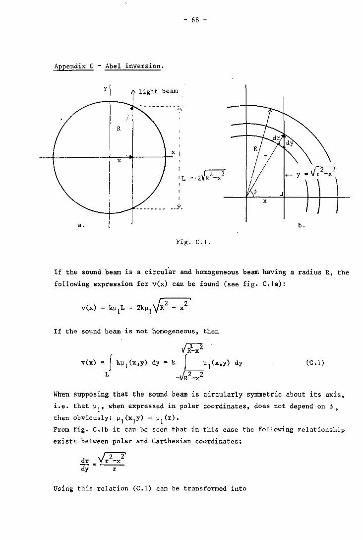
- 68 -
Appendix C - Abel inversion.
yl l' light beam
,.\
R
__ ~ __ . __________ ~~~ ______ -+_x I x
a. b.
Fig. C.1.
If the sound beam is a circular and homogeneous beam having a radius R, the
following expression for vex) can be found (see fig. C.la):
vex) = k~ L = I
2 - x
If the sound beam is not homogeneous, then
Il-x2 vex) = J
L
k~l(x,y) dy = k J ).I1(><'y) dy
_JR2_x2 (C. I )
When supposing that the sound beam is circularly symmetric a~out its axis,
i.e. that ~I' when expressed in polar coordinates, does not depend on ~,
then obviously: ~1(xIY) = ~I(r).
From fig. C.lb it can be seen that in this case the following relationship
exists between polar and Carthesian coordinates:
Using this relation (C.I) can be transformed into
- 69 -
R
r )Jl(r).r.dr
= 2k x' Vr2 - x2 '
vex)
By means of the Abel inversion (ref. 32) this last equation can be trans-
formed into
! = -- (C.2)
1f
From (C.2) it can be seen that the transformation from v(x) to k)Jl(r) is
a linear transformation. Consequently (C.2) may be written as a matrix
equation. This can be done in the foll~wing way: ..
Let - as a result of one of the computations given ~n appendix B - v be
given as a sequence of n values of v(x.) for equidistant x. values ~ ~
(i = 1.2 ...... n; xl = O. xn = R).
Let k;1 be given as a sequence of n values of k)Jl(r i ) for equidistant ri
values (i = 1.2 ••••• n; r 1 = O. rn = R).
In that case the following expression is completely equivalent to (C.2):
in which A is a n x n transformation matrix.
The values of the elements of A have been tabulated by Bockasten (ref. 32)
for n = 10 and for n = 20.
Appendix B has dealt with methods for calculation of the values of v(x)
from the measured light intensities in the diffraction pattern. In appendix
C an additional method has been derived that permits the calculation of the
amplitude of the variation of the refractive index as a function of the
position in the sound beam. This method s~arts from the values of vex) and
makes use of the assumption that the sound beam is circularly synunetric.
- 70 -
Appendix D - The sound intensity.
As a result of the Abel inversion we have obtained a sequence of values
k~l{ri)' by which the function
fer) = k~1 (r) (D. I)
is determined. From this function the local sound intensity I = I (r) may a a
be calculated. According to the law of Lorentz-Lorenz the following ex-
pression will hold for any medium:
l + 2 -"-;;--'-':: = Ap ~2 _ 1
A being the molar refractivity of the medium.
Differentiation and evaluation of the result gives:
-6~p dp = -;;-2....::..t:"--:2::--- • d~
(~ -I)(~ +2)
Since ~I « ~o holds:
-6~ p o 0
p 1 = --::'2 ::""'::'--;;-2 -. ~ I (~ -I)(~ +2)
o 0
in which:
PI' ~I = amplitudes of density and refractive index.
Po' ~o = density and refractive index at rest.
(D.2)
In acoustical textbooks the following formula can be found for the sound
intensity I : a
I = a
(D.3)
Substitution of (D.I) and· (D.2) into (D.3) gives:
a is
if A
in which
temperature-dependent. If -7
= 6,328.10 (He-Ne laser),
2 3 ! 8~ p c
a = -.2,..--,.::.0_0=-,2=---"'"2 k (~ -I) (~ +2)
o 0
the medium consists of distilled water and
then it may be calculated that (ref.34):
- 71 -
-6 2 -3 a = -8.10 .t + 1,14.10 .t + 0,1040
At 20°C this leads to:
I (r) = O,1236.f2(r)
a
- 72 -
Acknowledgements
The author wish to thank Prof.dr. C.E. Mulders for critically reading
the manuscript of this report, Mrs. G. Huibers-Weckx for the attention
paid at the accurate type-writing of the text and Mrs. C. Carp for
the kind and educative way, in which she has transformed the author's
English into real English.
- 73 -
References
1. D. Gordon (edit.); "Ultrasound as a diagnostic and surgical tool".
Livingstone, Edinburgh, 1964.
2. B. Brown, D. Gordon (edit.); "Ultrasonic techniques in biology and
medicine". London, Iliffe books, 1967.
3. R.M. Kenedi (edit.); "Biomedical applications of ultrasound; in: advances
in biomedical engineering". London - New York, Aoademio Press, 1971.
4. P.T.N. Wells; "The medical applications of ultrasonics". Reports on
progress in physios, vol. 33, 1970, pp. 45/99.
5. W.D. Ulrich; "Ultrasound dosage for experimental use on human beings".
Researoh Report no. 2, Nav. Med. Res. Inst., Bethesda, 1971.
6. C.R. Hill; " The possibility of hazard in medical and industrial appli
cations of ultrasound". Brit .. J. of Rad., vol. 41, 1968, pp. 561/569.
7. I.G. Mikhailov; "Methods of measuring the absolute intensity of ultra
sonic waves in liquids and solids". UttraBonias, vol. 2, 1964, pp.
129/133.
8. W.J. Fry, R.B. Fry; "Determination of absolute sound levels and acoustic
absorbtion coefficients by thermocouple probes". J. Ao. Sao. Amer.,
'701. 26, 1954, pp. 294/317.
9. R.J. Bobber; "General reciprocity parameter" • • T. Ao. Sao. Amer., vol.
39, 1966, pp. 680/687.
10. H. Diet:rick et al.; "Ultrasonic waves and electrochemistry, part III".
J. Ao. Sao. Amer., vol. 25, 1953, pp. 461/465.
11. L. Brillouin; Ann. Phys. (Franoe), vol. 7, 1922, pp. 88.
12. P. Debije, F.W. Sears; Proo. Nat. Aoad. Sci (U.S.A.), vol. 18, 1932,
pp. 409.
13. R. Lucas, P. Bicquard; J. Phys. Rad., vol. 3, 1932, pp. 464.
- 74 -
14. C. V. Raman, N.S.N. Nath;, " The diffraction oJ; light by high frequency
sound waves". Proc. Ind. Acad. Sci.,vol. 2, 1935, pp. 406/412 and
pp. 413/420, vol. 3, 1936, pp. 75/84, 119/125 and 459/465, vol. 4, 1936,
pp. 222/242.
15: F.H. Sanders; Can. J. Research (AJ, vol. 14, 1936, pp.158.
16. P. Debije, H. Sack, F. Coulon; Compt. rend. , vol. 198, 1934, pp. 922.
17- O. Nomoto, K. Negishi; "Diffraction of light by ultrasonic waves of
finite amplitude". Acustica, vol. 15, 1965, pp. 223/235.
18. K.L. Zankel, E.A. Hiedemann; "Diffraction of light by ultrasonic waves
progressing with finite but moderate amplitudes in liquids". J. Ac.
Soc. Amer., vol. 31, 1959, pp. 44/54.
19. L.E. Hargrove; "Exact simplification of time-dependent ultrasonic
standing wave light diffraction equations". J. ,"Ac. Soc. Amer., vol. 41,
1967, pp. 91/92.
20. W.R. Klein, B.D. Cook; "Unified approach to ultrasonic light diffraction".
I.E.E.E. trans. , SU vol. 14, 1967, pp. 123/134.
21. B.D. Cook, E.A. Hiedemann; "Diffraction of light by ultrasonic waves
of various standing wave ratios". J. Ac. Soc. Amer., vol. 33, 1961,
pp. 945/948.
22. J.S. Murty; "Theoretical investigation on the diffraction of light by
superposed ultrasonic waves". J. Aa. Soc. Amer;, vol. 26, 1954, pp.
970/974.
23. L. E. Hargrove, E.A. Hiedemann; "Diffraction of wide and narrow light
beams by distorted finite-amplitude progressive ultrasonic waves in
,,'ater". J. Ac. Soc. Amer., vol. 33, 1961, pp. 1747/1749.
24. W.R. Klein, B.D. Cook, W.G. Mayer; "Light diffraction by ultrasonic
gratings". Acustica, vol. 15, 1965, pp. 67/74.,
25. L.E. Hargrove, K.L. Zankel, E.A. Hiedemann; "Effects of a progressive
ultrasonic wave on a, light beam of arbitrary width". J. Ac. Soc.
Amer., vol. 31, 1959, pp. 1366/1371.
- 75 -
26. R. Mertens; "On the theory of the diJfraction of light by two parallel
ultrasonic waves, one being the nth hannonic of the other". Zeitschr.
f. Physik, vol. 160, 1960, pp. 291/296.
27. B.D. Cook; "Detennination of finite amplitude distortion by light dif
·fraction". J. Ac. Soc. Amer., vol. 32, 1960, pp. 336/337.
28. B.D. Cook; "Optical method for ultrasonic wavefonn analysis, using a
recursion relation". J. Ac. Soc. Amer., vol. 37, 1965, pp. 172/173.
29. M. V. Berry; "The diffraction of li,ght by ultrasound". London-New York,
Academic Press, 1966.
30. P. Phariseau; "On the diffraction of light by progressive supersonic
waves". Pmc. Ind. Ac. Sci, vol. 44, 1956, pp. 165/170.
31. E.A. Hiedemann, K.L. Zankel; "The study of ultrasonic wavefonn by optical
methods". Acustica, vol. II, 1961, pp. 213/223.
32. K. Bockasten; "Transfonnation of observed radiances into radial distri
bution of the emission of a plasma". J. Opt. Soc. Americ., vol. 51,
1961, pp. 943/947.
33. I.S. Gradsteyn, I.M. Ryzhik; "Table of integrals, series and products".
London- New York, Academic Press, 1965.
34. Landolt - Bornstein (edit.); "Zahlenwerte und Functionen". RerUn,
Springer, 1967.
35. L.M,H, Faessen; "On the measurement of the acoustic intensity of an
ultrasonic beam by means of light diffraction". (in Dutch)
M.Sc.-thesis, Univeraity Of TechnoZogy, Eindhoven, the NetherZands, 1974.
- 76 -
List of symbols.
A amplitude of light wave.
E absolute value of the electrical component of light wave; energy.
I light intensity.
I sound intensity. a J Bessel function of the first kind.
L length of the light path through the sound field.
Q parameter of the diffraction equation. -+
b,b wave number, wave vector of sound.
c velocity of light in vacuum.
ca velocity of sound in the medium.
d width of the light beam. -+
k,k wave number, wave vector of light.
m mass.
n ordinal number of diffracted light beams.
p momentum.
s ordinal number of sound harmonic; angular momentum.
t time; temperature.
v parameter of the diffraction equation.
a angle of incidence of light on sound.
S parameter of the diffraction equation.
o phase term; loss of momentum.
e angle of diffraction.
A wavelength of light in resting medium.
Aa wavelength of sound.
~ refractive index.
~o refractive index in absence of sound.
~1 perturbation of refractive index dae to the sound.
p density.
¢ phase term.
w frequency of light.
~ time-independent wave function: E = ~.eiwt n frequency of sound • ... e uni ty vector. -+ r radius vector •
.fJ. Dirac's constant:.fJ. = h/2rr = 1.054.10-34 Js
i =FI
TH-Reports:
EINDHOVEN UNIVERSITY OF 'tECHNOLOGY
THE NETllRRLANDS
DEPARTMENT OF ELECTRICAL ENGINEERING
1. Dijk. J., M. Jeuken and E.J. Maanders
AN ANTENNA FOR A SATELLITE COMMUNICATION CROUND STATION (PROVISIONAL ELEC
TRICAL DESIGN). TH-report 60-E-Ol. March 1968. ISBN 906144001 7.
2. Veefkind, A" J.R. Blom and L.R.Th. Rietjens.
THEORETICAL AND EXPERIMENTAL INVESTIGATION OF A NON-EQUILIBRIUM PLASMA
IN A MHD CHANNEL. TR~report 68-E-2. March 1968. ISBN 90 6144 002 5.
Submitted to the Symposium on a Magnetohydrodynamic Electrical Power Ge
neration, Warsaw, Poland, 24-30 July, 1968.
3. Boom, A.J.W. van den and J.H.A.M. Melis.
A COMPARISON OF SOME PROCESS PARAMETER ESTIMATING SCHEMES.
TR-report 68-E-03. September 1968. ISBN 90 6144 003 3.
4. Eykhaff. P., P.J.H. Ophey, J. Severs and .LO.M. Dome.
AN ELECTROLYTIC TANK FOR INSTRUCTIONAL PURPOSES REP,RESENTING THE COMPLEX
FREQUENCY PLANE. T.H-report 68-E-04. September 1968. ISBN 90 6144 004 I.
5. Vermij, L. and J.E. Daalder.
ENERGY BALANCE OF FUSING SILVER WIRES SURROurWED BY AIR.
TH-report 68-E-05. November 1968. ISBN 90 6144 005 X.
6. Houben. J.W.M.A. and P. Massee.
MHD POWER CONVERSION EMPLOYING LIQUID METALS.
TH-Report 69-E-06. February 1969. ISBN 90 6144 006 8.
7. heuvel. W.M.C. van den and W.F.J. Kersten.
VOLTAGE MEASUREMENT IN CURRENT ZERO INVESTIGATIONS.
TH-Report 69-E-07. September 1969. ISBN 90 6144 007 6.
8. Vermij. 1.
SELECTED BIBLIOGRAPHY OF FUSES.
TH-Report 69-E-08. September 1969. ISBN 90 6144 008 4.
9. ~estenberg, J.Z.
SOME IDENTlFICATION SCHEMES FOR NON-LINEAR NOISY. PROCESSES.
TH-Report 69-E-09. December 1969. ISBN 90 6144 009 2.
10. Koop, H.LM., J. Dijk and E.J. Maanders.
O~ CONICAL HORN ANTENNAS.
TH-Report 70-E-IO, February 1970. ISBN 90 6144 010 6.
II. Veefkind, A.
NON-EQUILIBRIUM PHENOMENA IN A DISC-SHAPED MAGNETDHYDRDDYNAMIC GENERATOR.
TH-Report 70-E-11. March 1970. ISBN 906144011 II.
12. Jansen, J.K.M., M.E.J. Jeuken and C.W. lambrechtse.
THE SCALAR FEED.
TH-Report 70-E-12. December 1969. ISBN 90 6144 012 2
13. Teuling, D.J .A.
ELECTRONIC IMAGE MOTION COMPENSATION IN'A PORTABLE TELEVISION CAMERA.
TH-Report 70-E-13. 1970. ISBN 90 6144 013 O.
14. Lorencin. M.
AUTOMATIC METEOR REFLECTIONS RECORDING EQUIPMENT.
TH-Report 70-E-14. November 1970. ISBN 90 6144 014 9.
15. Sruets, A.J.
THE INSTRUMENTAL VARIABLE METHOD AND RELATED IDENTIFICATION SCHEMES.
TH-Report 70-E-15. November 1970. ISBN 90 6144 015 7.
16. White, Jr., R.C.
A SURVEY OF RANDOM METHODS FOR PARAMETER OPTIMIZATION.
TH-Report 70-E-16. February 1971. ISBN 90 6144 016 5.
17. Talman. J.L~
APPROXIMATED GAUSS::'MARKOV ESTIMATORS AND RELATED SCHEMES.
TH-Report 71-E-17. February 1971. ISBN 90 6144 017 3.
18. Kalasek, V.
MEASUREMENT OF TIME CONSTANTS ON CASCADE D.C. ARC IN NITROGEN.
TH-Report 71-E-IB. February 1971. ISBN 90 6144 018 1.
19. Hosselet, L.M.L.r.
OZONBILDUNG MITTELS ELEKTRISCHER ENTLADUNGEN.
TH-Report 71-E-19. March 1971. ISBN 90 6144 019 X.
20. Arts, M.G.J.
ON THE INSTANTANEOUS MEASUREMENT OF BLODDFLOW BY ULTRASONIC MEANS.
TH-Report 71-E-20. May 1971. ISBN 90 6144 020 3.
21. Roer, Th. G. van de
NON-ISO THERMAL ANALYSiS OF CARRIER WAVES IN A SEMICONDUCTOR.
TH-Report 71-E-21. August 1971. ISBN 90 6144 021 I.
22. Jeuken, P.J., C. Huber and C.E. Mulders.
SENSING INERTIAL ROTATION WITH Tli~ING FORKS.
TH-Report 71-E-22. September 1971. 1SBN 90 6144 022 X.
23. Diik. J. and E.J. Maanders
APERTURE BLOCKING IN CASSEGRAIN ANTENNA SYSTEMS. A REVIEW.
TH-Report 71-£-23. September 1971. ISBN 90 6144 023 8
24. Kregtins, J. and R.C. Hhitc, Jr.
ADAPTIVE RANDOM SEARCH.
TH-Report 71-E-24. October 1971. [SBN 90 6144 024 6
25. Damen, A.A.H. and B.A.L. Piceni.
THE MULTIPLE DIPOLE MODEL OF THE VENTRICULAR DEPOLARISATION
TH-Report 71-E-25. October 1971. ISllN 90 6144 025 4
26. Bremmer, H.
A MATHEMATICAL THEORY CONNECTING SCATTERING AND DIFFRACTION PHENOMENA'
INCLUDING BRAGG-TYPE INTERFERENGES.
Tll-Report 71-E-26. December 1971. ISBN 90 6144 026 2.
27. Bokhoven; \.-i.H.G. van
METHODS AND ASPECTS OF ACTIVE-RC FILTERS SYNTHESIS.
TH-Report 71-E-27. 10 December 1970. ISBN 90 6144 027 O.
28. Boeschoten. F.
TWO FLUIDS MODEL REEXA}1INED.
Tn-Report 72-£-28. March 1972. ISBN 90 6t44 02B 9.
29. Rietiens, L.H. Th.
REPORT ON THE CLOSED CYCLE. I-flID SPEC IALIST MEETTNC. WORKING GROUP OF THE
JOlt-:T ENEA: J AEA INTERNAT lONAL MHD LIAISON GROUI' AT E lNDHOVEN. THE NETHER'·
LANUS. September 2U, 21 and 22. 1971.
TH-Report 72-E-29. April 1972. ISBN 90 6144 029 7
30. C.G.t-I. van K.;,ssel and J.W.t-I.A. Houben.
LOSS HECIi.ANISHS IN AN MHU-GENERATOR.
TH-Repurt 72-E-30. June 1972. ISBN 90 6144 030 O.
3t. A. Veefkind.
CONDUCTING GUIDS TO STABILIZE MHD-GENERATOH. PLASMAS AGAINST IONIZATION
INSTABILITIES. TH-Report 72-E-31. October 1972. ISBN 90 6144 031 9.
32. J.E. Daalder and C.W.H. Vos.
DISTRIBUTION FUf\CTlOf\S OF"THE SPOT-DIAHEIER FOR SINGLE- AND MULTI-CATHODE
DISCHARGES It-: VACUUM. TH-Report 73-E-32. January 1973. ISBN 90 6144 032 7.
33. J.E. [)aaldcr.
JOl'LE HEATING A}:D DIAHETER Of THE CATHODE SPOT IN A VACUUM ARC.
TH-Report 73-E-33. January 1973. ISBN 90 6144 033 5.
34. Huber, C.
BEHAVIOl..:R OF THE SPINKING GYRO ROTOR.
Ih-Report 73-E-34. February 1973. ISBN 90 6!!14 034 3.
35. Boeschoten. F.
THE \'ACl!L'M ARC AS A FACILITY FOR RELEVANT EXPERIMENTS IN FUSION
RESEARCH.
TH-ReporL 73-E-35. February 1973. ISBN 906144035 I.
3b. Blom. J.A.
A~ALYSIS OF PHYSIOLOGICAL SY$TENS BY PARAHETER ESTIM,r\TION TECHNIQUES.
73-E-36. 1973. ISBN 90 6144 036 X
37. Lier, !-1.C. van and R.Il.J.H. Otten.
AUTO~7IC WIRING DESIGN.
TH-reprot 73-E-37. Hay 1973. ISBN 90 6144 037 8
38. Andriessen. F.J.
CALCULATION OF RADIATION LOSSES IN CYLINDRICAL SYMMETERICAL HIGH
PRESSURE DISCHARGES BY r-lEANS OF A DIGITAL COMPUTER.
IH-report 73-£-38. October 1973. ISBN 90 6144 038 6
39. Dijk. J., C.LI-'. ,,'an Dicpenbcck, EoJ. Nannderl' and LF.C. Thurlings.
THE POLARIZATION LOSSES OF OFFSET ANTENNAS.
TH-repore 73-E-19. June 1973. IS.H~ 90 11144 019 4.
40. Goes, W.P.
SEPAH.ATlON OF SIGNALS DUE TO ARTI~RL\L A.NIl VENOUS lIJ.()nIlFLO\~. IN TIlE
DIlPPLER SYSTEM, TJlIIT USI':S CONTIN11()lIS llJ.TH.AS(llINJ).
Til-report 73-E-40. SL'pteml>L'r 1973. ISlIN 9U hl44 0408
41. Dame", A.A.I1.
A COMPARATIVE ANALYSIS OF SEVERAL HODELS OF TilE VENTRICULAR DEPOLARl
SATION; INTRODUCTION UF II STRING HOl>El,.
TH-report 73-E-41. October 1973. ISBN 90 6144 041 6.
42. Dijk. G.H.M. van.
THEORY OF GYRO WITH ROTATING CI~mAL AND FLEXl'RAL PIVOTS.
TH-report 73-E-42. September 1972. ISBN 90 6144 042 4.
43. Breimer. A.J.
ON THE IDENTIFICATION OF CONTINUOUS LINEAR PROCESSES.
TH-report 74-E-43. Jan~ary .1974. ISBN 90 6144 043 2.
44. Lier. M.C. van and R.H.J.M. Otten.
C.A.D. OF MASKS AND WIRING.
TH-report 74-E-44. February 1974. ISBN 90 6144 044 O.
45. Boeschoten. F.
EXPERIMENTS WITH A LARGE SIZED HOLLOW CATHODE DISCHARGE FED WITH ARGON.
TH-report 74-E-45. April 1974. ISBN 90 6144 045 9.
46. Roer. T.G. v.d.
AN ANALYTICAL SMALL-SIGNAL THEORY OF BARITT-DIODES.
TH-report 74-E-46. May 1974. iSBN 90 6144 046 7.
47. Leliveld. W.H.
THE DESIGN OF A MOCK CIRCULATION SYSTEM •
. TH-report 74-E-47. June 1974. ISBN 906144 047 5.
48. Darnen. A.A.:!!.
SOME NOTES ON THE INVERSE PROBLEM IN ELECTROCARDIAL GRAPHY.
TH-report 74-E-48. August '74. ISBN 90 6144 048 3.-
49. Meeberg, L. v.d.
A BITE RBI DECODER.
TH-report 74-E-49. October '74. ISBN 90 6144 049 I
50 Poel, v.d. A.P.M.
A COMPUTER SEARCH FOR GOOD CONVOLUTIONAL CODES.
TH-report 74-E-50. October '74. ISBN 90 6144 050 5
51. Sampic, G.
THE BIT ERROR PROBABILITY AS A FUNCTION PATH REGISTER LENGTH IN
THE VITERBI DECODER.
TH-report 74-E-51. October '74. ISBN 90 6144 051 3
52. Schalkwijk, prof. dr.ir. J.P.M._
CODD'G FOR A CONPUTER NETWORK.
TH-report 74-E-52. October '74. ISBN 90 6144 052 I.