4K / UHD Two-Input Wallplate Switcher for HDMI and USB-C ...

Smal
l Too
l Ins
trum
ents
and
Data
Man
agem
ent
Measurement Data Input UnitUSB Input Tool Series
Catalog No. E12007(3)

32
The USB Input Tool lets you send measurement data to a computer at the simple push of a button.
No need for initial setup, and cost is eminently affordable.
Still entering measurement results manually into a check sheet?Read scale Use the keyboard to create
inspection certificateEnter values into check sheet
Misreadings may occur
Wrong values may be
entered
Typing mistakes may
occur
The USB Input Tool requires no setup and is very reasonably priced. It is ideal for moving away from manual recording and for maintaining quality records in electronic form, which are vital first steps towards higher inspection efficiency and reliability. An existing measuring tool with Digimatic output can be used. Simply purchase the USB Input Tool and use it to send measurement data to a personal computer (a connecting cable is required depending on the models). Two different series are available in various configurations to fit different application scenarios.
See page 4,5 See page 4,5
Optional Software USB-ITPAK V2.1 Pages 7-9
IT-016U Page 4 and 5USB-ITN Page 4 and 5IT-007R Page 6
Input Tool Series
Connecting Configuration / Specifications
Measuring Tool Compatibility List Pages 10-11
Use your existing measuring tool equipped with a data output
Remove the cover to access the output connector
Digimatic Indicator Water-proof Digimatic Micrometer
Digimatic Height Gage Hardness Testing Machine (rear view)
Production Line Surface Roughness Measuring Instrument
You may already own a measuring tool that can be used. See the photographs below to check whether it has a Digimatic output connector. The connector type may be different, depending on the measuring tool model. See the list showing measuring tool compatibility on pages 10 and 11.
Requires separate connecting cable
New model
Old-model Digimatic Micrometer
Simply connect to the USB port of a computerWithout needing special software or initial setup, the data can be used in any general-purpose software application that accepts numeric input from a keyboard, such as Excel, Word, Notepad, etc.
The USB Input Tool will be recognized as a USB numeric keypad
=When connected, the USB Input Tool is recognized automatically as an HID (Human Interface Device) keyboard (using the standard Windows driver).
Using digital measuring tools together with the USB Input Tool makes recording measurement results more efficient and improves data reliability.
Digimatic micrometer USB Input Tool IT-016U(Requires separate connecting cable)
Windows Device Manager screen
Taskbar indication
Same result as when typing numbers with the keyboard and then pressing Enter.
Send to computer at the push of a button
Measuring Tool with Digimatic Output
Connecting cable (optional)Refer to page 5, 10, and 11 for details.
USB Input Tool IT-016U USB Input Tool Direct USB-ITN

54
IT-016U/USB-ITN Connection Configuration and main specifications
Connecting cable (optional)
External view of IT-016U
Connector shape
A
B
C
D
E
F
G
Connect the Digimatic connector to the gage
C
B
F
Digimatic gages
USB Input ToolIT-016U
USB InputTool Direct USB-ITN
Foot Switch (optional)
Connecting cable (optional)
PC
Digimatic caliper
Digimatic indicator
Digimatic micrometer
Refer to pages 10 and 11 for details of Digimatic ports and connectors.
Refer to pages 10 and 11 for details.
Connector 7 types (A to G) + 4 L types
USB keyboard signal conversion modelModel: IT-016UOrder No. 264-016-10
1)
Cable length: 1 m or 2 m
1)
Merely connecting this tool to a PC allows measurement data to be input to Excel, Memo Pad, etc.Two types of USB input tools are available depending on your purpose.
System Environment• Supporting model: PC with USB socket (Type A)• Hardware:
Windows 2000 SP4Windows XP SP2 or laterWindows VistaWindows 7Windows 8 /8.1 Windows 10
• Software (when single HD is connected):
Programs supporting keyboard input (Excel, Word, memo pad, etc.)
USB socket(Type A)
Connection port
Connect the unit to a USB port of the PC
USB-ITPAK V2.1 (optional)
Foot switch (optional) mold type12AAJ088Available for both USB-FSW and IT-007R. DP-1VR is not connectable.
Cable length: 2 m
Foot switch (optional) resin type937179T
1)
Gage selector 3 (optional)939039 This selector can
connect up to 3 measuring gages and switching is available with the slide switches without changing connecting cables. Connecting cable (length 1 m) between two input tools is a standard accessory (936937).
Measurement Data Collection SoftwareUSB-ITPAK V2.1 (optional)
06AFM386
USB Input Tool Direct USB-ITN
Common specifications• Output compatibility:
USB2.0 or USB1.0• Supporting driver software:
Switchable between 2 models(1) When using standalone:
HID keyboard device*(2) When using with USB-ITPAK V2.1• Communication speed:
12 Mbps (Full Speed)• Power supply: USB bus power• USB2.0 certificate• Conforms to EU EMC Directives.* Since this device is compatible with
Windows standard driver software, dedicated driver software is not required.
Connect the unit to a serial port of the PC
Type Order No. Data switchA 06AFM380A ✓B 06AFM380B ✓C 06AFM380C ✓D 06AFM380D –E 06AFM380E –F 06AFM380F –G 06AFM380G –
Connector shape
A
B
C
D
E
F
G
Connect the Digimatic connector to the gage Cable length: 2 m, mass: 50 g
Refer to pages 7 to 9 for details.
38
2164
DIGIMATIC
ø18
Terminal for Foot switchø3.5 dipole jack US type (input)
Digimatic connectorBox type plug 10P (input)
Data switch
USB connectorMicro B receptacle (output)
Micro B plug(Connect to input tool main unit)
USB cableA micro B type
Standard A plug (connect to PC)
Cable length=1 mMass: 56 g
2)
(2) USB Input Tool Direct (7 Models)
Box type equipped with a built-in data switch and an add-on foot switch terminal
Slimline, cable-integrated type
This interface box is provided with a larger data input switch compared with the old type (from ø4 mm to ø18 mm), improving operability.The switch has also widely increased in durability.(From million times to ten million times)
Easy data input is enabled by connecting the foot switch (optional). (The foot switch terminal comes standard.)
This tool is a cable-integrated type slimmed down by eliminating the interface box. It provides simple connecting to a PC and smooth cable routing, thus improving workability.
<Caution in combining with an instrument>
USB-ITN-D / E / F / G type which has no data switch on the connector part of the input tool cannot be used depending on the instrument to be combined.* In this case, use box type IT-016U with a data switch.
USB-ITN
IT-016U(1) USB Input Tool
The efficiency of recording inspection results in Excel has improved.
For the clients who feel that it is not enough to merely load numeric data into Excel, Mitutoyo has increased the efficiency of inspection task including repeated operations through the combination of optional software USB-ITPAK V2.1 that enables creation of inputting procedure to any Excel sheet. Usage example in combination with USB-ITPAK V2.1: Efficiency improvement in inspection tasks to be daily performed in the same repeated procedure such as sampling or 100% inspection of mass-produced products
Combination of IT-016U and Dedicated Option of USB-ITN For details, refer to pages 7 to 9.
Foot switch
IT-012U
IT-016U
ø18 mmø4 mm
Oldtype
Newtype
Note: If your tool is renewed from IT-012U, note that some instrument models may not be connected. Please refer to Note 2 in the List of Compatible Instruments on page 11.
USB Input Tool Connecting Configurations/Sp ecifications
* Please refer to Note 1 in the List of Compatible Instruments on page 11.

76
Input tool series RS-232C communication conversion type
Input tool for RS-232C communication best suited for communication control of the software.Control is available by transmitting data request commands via RS-232C communication.
For example, production engineers can create communication programs to load the measurement data by transmitting a command from the PC.This product is a compact and low-cost RS-232C communication interface, which is convenient when it is installed in a machine tool or dedicated device to feed back measurement data (for connection other than to a PC, a separate power supply is required).
IT-007R Connection Configuration and main specification
System Environment• Hardware: PC or sequencer with a serial
port (D-sub 9 pin)Note 1: Refer to “Connector specification and
power supply from the PC” below. When connecting to a sequencer, a power supply is required. Use at sufficiently long input intervals (one second or more is recommended).
• Software: A program compatible with the RS-232C
communication (such as a hyper terminal or MeasurLink® Serial Terminal) is required.
Note 2: Connecting with USB-ITPAK V2.1 is not available.
D-sub 9 pin
Connection portConnecting cable
(optional)
Data output is available by transmitting data request commands from the PC.
External view of IT-007R
Connector shape
A
B
C
D
E
F
G
Connect the Digimatic connector to the gage
Connect the unit to a serial port of the PC
C
B
F
Digimatic gagesInput tool
IT-007RFoot switch (optional)
Connecting cable (optional)
PC
Gage selector 3 (optional)
Digimatic caliper
Digimatic indicator
Digimatic micrometer
Refer to pages 10 and 11 for details of Digimatic ports and connectors.
[Data import method]· Data switch of Input Tool· Data switch of connecting cable· Data switch of Digimatic gages· Command transmission from PCOperate one of above four methods.
Foot switch (optional) resin type
Gage selector 3 (optional)
937179T
939039
Refer to pages 10 and 11 for details.
Connector7 types (A to G) + 4 L types
RS-232C communicationconversion typeModel: IT-007ROrder No. 264-007
2)1)
2)
Specifications of IT-007RRS-232C Communication• Output specification: RS-232C compliant· Communication method: Full duplex· Communication speed: 2400 bps (fixed)· Bit configuration: Start bit 1 Data length 8 (Most significant bit, 0 (fixed)) Parity, None Stop bit 1· Flow control: None· Home position: DCE (modem definition)• Data format
• Connector specification and power supply from the PC
This product operates while accumulating the power supplied from the PC. A second or more input interval is required.
• Data request signalData can be output by transmitting a character from the PC.
D-SUB 9 pin female
Mass: 91 g (including a cable)
Cable length: 0.9 m
GAGE
DATA
Digimatic input tetminal (flat 10 pin)Terminal for foot switch
44
7223
.5Pin No. Symbol in /out Description of functions1 (N.C.) − No connection2 RXD OUT Data output from this product to the PC3 TXD IN Data input from the PC to this product4 DTR IN +12 V power supply from the PC*5 GND − Ground6 DSR OUT Not used7 RTS IN +12 V power supply from the PC*8 CTS OUT Not used9 (N.C.) − No connection
* "4" and "6", "7" and "8" are short-circuited with each other inside this product. When connecting to a sequencer, a power supply is required.· Input voltage: Supplied in the range 6 V to 16 V· Power supply terminal: Supplied to pins 4 and 7
If the power supply is difficult, please consider to purchase MUX-10F (power supply by AC adapter and connectable with 4 units of Digimatic gages).
(1) When data output
(2) Error code output
D1 D2 D3 D4 D5 D6 D7 D8 D9 D10 D11 D12 D13“0 1 A” (fixed)
Signs, "+" or "-"
Output order →
CRData parts (Floating decimal point)
D1 D2 D3 D4“9 1” (fixed)
Error code No.“1” : No data input“2” : Loaded data with format other than specified
Example of format Display Output data 0.123 →01A+0000.123CR-0.1234→01A-000.1234CRCR
1)
GAGE DATA
⑤④③②①⑨⑧⑦⑥
Cable length: 1 m or 2 m
IT-007R
OptionalNote: These options are common for IT-016U, USB-ITN, and U-WAVE. They cannot be used with the IT-007R.
Measurement data collection software (IT-007R are not supported)
U-WAVE is measurement data wireless communication system. For the system summary, refer to the U-WAVE leaflet (Catalog E12000).
USB-ITPAK V2.1
USB Foot Switch Adapter USB-FSW
Input Tool Connection Configuration/Specifications
Upgraded USB-ITPAK V2.1 now supports U-WAVE, a wireless communication system. Both wired connecting (USB-ITN) and wireless system (U-WAVE) are supported.
Using together with USB-ITPAK V2.1 will further improve the operational efficiency of repetition inspection work. Best suited for keeping track of inspection data of mass-produced products.
Main features of USB-ITPAK V2.1
New functions of USB-ITPAK V2.1• Supports the U-WAVE wireless communication system • Timer input function
• Measurement date / time display• Others: Compatible with Windows 8, 64-bit OS, and Russian
included in the operating language selection
USB-ITPAK V2.1 creates a procedure to input data from gages equipped with Digimatic output to Excel sheets via IT-016U or USB-ITN or U-WAVE.
• Automatically calls Excel sheet.• Cursor moves can be specified.• Input range can be specified per Digimatic gage, which reduces
improper input.
• The last data input can be canceled by a single operation (foot switch, function key etc.)• Data input or cancellation can be performed at once in multiple-point simultaneous measurement.
• Setting of Microsoft Excel input: Designation of where to input (workbook, worksheet, cell range), cursor move (right, down), and others.
• Selection of measuring method (3 modes available) (1) Sequential measurement (2) Simultaneous measurement (3) Individual measurement (refer to page 11 for details).
• Data handling Commands available: "Data Output Request", "Data Cancel", "Data Skip", "Arbitrary Character Input" (available only after prior registration and with a foot switch) Command input methods: Pressing a mouse, function key, foot switch, etc. (available only with a foot switch in the discrete measurement mode)
• Number of connectable devices and others Connectable devices: (1) IT-016U, (2) USB-ITN, (3) USB-FSW, (4) U-WAVE-R (Each U-WAVE-R can accept measurement data from up to 100 registered instruments)
Number of connectable devices (total number of (1) (2) (3) (4) ): - 100 devices or less for Windows 2000 /XP - 20 devices or less for Windows Vista /7 /8 /8.1 /10 Number of registerable instruments (total number of (1) (2) (3) (4) ): 400 instruments or less Method to control / identify connected devices: VCP (Virtual COM Port) - for device types (1)
and (2), the driver software is switched from HID to VCP to apply this method.• Data loading time: when using IT-016U /USB-ITN, 0.2 s to 0.3 s per gage unit
U-WAVE event drive mode: 0.5 s data refresh interval• Timer input function (only in simultaneous measurement)
Input interval (time): 0.1 s* to 24 hours maximum * If a shorter time is set, a priority is given to the longer time compared with the actual
communication time.• Measurement date/time display function (available in sequential and simultaneous measurements)
The display format is subject to the setting of the Excel sheet.
Operating environment Language support• Operation language (15 languages)
Japanese, English, German, French, Spanish, Italian, Czech, Swedish, Turkish, Polish, Hungarian, Russian, Korean, Chinese (traditional / simplified)
• Operation manual (PDF file) Japanese, English, German
• USB ITPAK V2.1 and the PC Operating System must use the same natural language.
USB-ITPAK V2.1 USB dongle
A USB dongle must be connected to the PC running the software.
Compatible OS*1Windows 2000 SP4, Windows XP SP2 or later, Windows Vista, Windows 7, Windows 8, Windows 8.1, Windows 10
Supported Excel versions*2
Excel 2002, Excel 2003, Excel 2007, Excel 2010, Excel 2013, Excel 2016
Hard disk Free space of more than 10 MBCD-ROM drive For program installationUSB port*3 2 ports or more (for USB dongle and USB-ITN)Monitor resolution 800×600, 256 colors or more
*1 32-bit, 64-bit OS supported*2 Operation with Excel for MAC OS is not guaranteed.*3 A commercially available hub can be used.
(USB certified product is recommended)
Order No. Model No. USB-ITPAK V2.1Order No. 06AFM386Upgrade pricing from V1.0 is not available. Please purchase V2.1.
• USB-ITPAK V2.1 supports use of the foot switch for data handling.• Data control: “Data request”,“Data cancel”, “Data skip”• Character string input (e.g. GO/NG, etc.)* USB-FSW is used for installation of the VCP driver.
Main specification
USB-FSW
Foot switch (937179T)
Order No.
Foot Switch Adapter USB-FSW
Model No. USB-FSWOrder No. 06ADV384
Overall length: 160 mm
Output data by causing a contact signal from the Foot Switch.
MONO (ø3.5) 2-CON.MINIATURE PLUG US Type
This USB adapter for connecting a PC is required when using the Foot Switch (937179T) in USB-ITN. A dedicated VCP driver* for this adapter is included in USB-ITPAK V2.1.
External view Unit: mm
<TIP> Refer to the USB-ITPAK V2.1 user's manual on the Mitutoyo website. https://www.mitutoyo.co.jp/eng/

98
Sequential measurement
Measurement values are input one by one according to a procedure previously defined by using one or more Digimatic gages (via IT-016U or USB-ITN or U-WAVE).
H
Y
X
Several operators input measurement data asynchronously according to individually defined procedures (where to input, move direction, etc.) from each Digimatic gage via IT-016U or USB-ITN or U-WAVE.
Notes on using USB-ITPAK V2.1:Do not merge the cells in the specified range as a measurement data input.During measurement, the Microsoft Excel worksheet cannot be modified in any way apart from entering data. If you need to modify the sheet, it is necessary to abort or finish the measurement.
B
AC
A B C D E F G1 Setting 1 2 3 4 5 6
2 Dimension A 10.02 10.03 9.96 10.15 10.23 10.04
3 Dimension B 9.98 10.01 10.07 9.99 9.78
4 Dimension C 10.15 10.14 9.96 10.27
Cell that will receive next input Cell that will receive next inputOperator 1 Operator 2
Simultaneous measurement
Individual measurement
Since several individual operators perform measurement simultaneously, an operation key and a function key in the window below cannot be used at the same time. The only effective input device in this case is the foot switch (via USB-FSW).
OptionalNote: These options are common for IT-016U, SB-ITN and U-WAVE.
They cannot be used with the IT-007R.
<TIP> User's manual for USB-ITPAK V2.1 is posted on our website with details of setting procedures, etc. https://www.mitutoyo.co.jp/eng/
A B C D E F
1 Setting 1 2 3 4 5
2 Dimension X 10.025 10.033 9.964 10.031 10.046
3 Dimension Y 9.982 10.017 10.008 9.996 10.027
4 Dimension H 29.97 30.02 30.07 29.96 30.04
5 ExternalAppearance OK OK NG
Microsoft Excel sheet previously specified
Input range of micrometer (B2 to F3)
Input range of caliper (B4 to F4)
Input range of visual judgment (B5 to F5)
Cell that will receive next input is highlighted in green
Cell movement direction after inputting data (down and right)
Carriage return (Low, column)
First measurement (finished)Second measurement (finished)Third measurement (finished)Fourth measurement (Wait for next input)
A B C D E
1 Height A Height B Height C Height D
2 1 5.02 8.03 9.96 6.03
3 2 4.98 8.02 10.01 5.99
4 3 4.97 8.04 10.07 5.96
5 4
6 5
<Measurement examples>Simultaneous measurement of the heights A to D on the workpiece below.
Measurement values are input simultaneously from several Digimatic gages (via IT-016U or USB-ITN or U-WAVE)
<Measurement examples>Two operators measure 6 workpieces (threeeach, both working at the same time)
measurement examples: 3 measurement methods by USB-ITPAK V2.1 are explained with example below.
Character strings
Input “OK”
Character strings
Input “NG”
Data request*
Data cancel
USB-FSW×4 pcs. +Foot switch×4 pcs.
USB hub (Commercial item)The last data input may be cancelled by pressing and holding the data switch
U-WAVE-T
U-WAVE-R
USB-ITN-C
USB-ITN-C×2 USB-FSW×2 pcs. +Foot switch×2 pcs.
Data request
Data cancelHeight A B C D
U-WAVE-R
U-WAVE-T×2 pcs.
USB-FSW×4 pcs.+Foot switch×4 pcs.
Data request
Data cancelWorkpiece Nos. 1 to 3 Workpiece Nos. 4 to 6
Operator 1
USB-ITN-C U-WAVE-T
Operator 2
The last data input may be cancelled by pressing and holding the data switch
U-WAVE-R
Note: During batch measurement, U-WAVE works in event drive mode.
USB-ITPAK V2.1
(3) Inspect external view to check if there are any scratches or color shading and input “OK” or “NG”.
(2) Measure length H of 5 workpieces.
(1) Measure outside diameter at X and Y of 5 workpieces with a micrometer.
<Measurement examples>Outside diameter in X and Y directions and length H for the workpiece below are measured in order for 5 pieces and finally perform OK/NG judgement for external view by visual check (scratches, color unevenness, etc.).
USB hub (Commercial item)
USB hub (Commercial item)
When a measuring procedure is executed, a window (as below) is displayed. “Data request*”, “Data cancel*”, “Data skip*”, “Aborting”, “Complete” can be specified.* These operations can be allocated to the function key or foot switch (via USB-FSW).
* No data request for U-WAVE.
1110
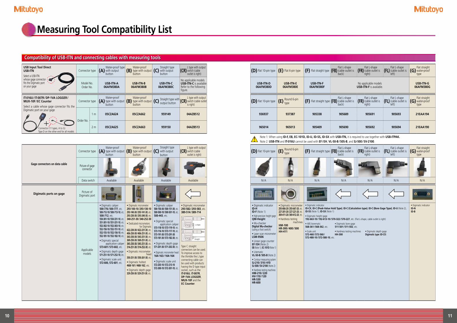
Measuring Tool Compatibility List
Compatibility of USB-ITN and connecting cables with measuring tools
USB Input Tool Direct USB-ITN
Select a USB-ITN whose gage connector fits the Digimatic port on your gage
Connector type (A)Water-proof type with output button
(B)Water-proof type with output button
(C)Straight type with output button
(CR)L type with output switch (cable outlet is right)
Model No.Order No.
USB-ITN-A06AFM380A
USB-ITN-B06AFM380B
USB-ITN-C06AFM380C
No applicable modelsUSB-ITN-C is availableRefer to the following figure.
IT-016U/IT-007R/DP-1VA LOGGER/MUX-10F/EC Counter
Select a cable whose gage connector fits the Digimatic port on your gage
Connector type (A)Water-proof type with output button
(B)Water-proof type with output button
(C) Straight type with output button (CR)
L type with output switch (cable outlet is right)
Order No.
1 m 05CZA624 05CZA662 959149 04AZB512
2 m 05CZA625 05CZA663 959150 04AZB513
Gage connectors on data cable
Connector type (A)Water-proof type with output button
(B)Water-proof type with output button
(C)Straight type with output button
(CR)L type with output switch (cable outlet is right)
Picture of gage connector
Data switch Available Available Available Available
Digimatic ports on gage Picture of Digimatic port
Applicable models
• Digimatic caliper500-776/500-777, etc.500-712-10/500-713-10, etc.500-712, etc.550-301-10/550-331-10, etc.551-301-10/551-331-10, etc.552-302-10/552-303-10, etc.552-150-10/552-151-10, etc.552-155-10/552-156-10, etc.552-181-10/552-182-10, etc.
• Digimatic special application caliper
573-601/573-602, etc.
• Digimatic depth gage571-251-10/571-252-10, etc.
• Digimatic scale unit572-600, 572-601, etc.
• Digimatic micrometer293-100-10/293-130-10293-140-30/293-141-30, etc.293-230-30/293-240-30, etc.340-251-30/340-252-30
• Dedicated micrometers for Digimatic
422-230-30/422-231-30, etc.406-250-30/406-251-30, etc.343-250-30/343-251-30, etc.369-250-30/369-251-30, etc.345-250-30/345-251-30, etc.314-251-30/314-252-30, etc.• Digimatic micrometer
head350-251-30/350-261-30, etc.
• Digimatic holtest468-161/468-162, etc.
• Digimatic depth gage329-250-30/329-251-30, etc.
• Digimatic caliper500-150-30/500-151-30, etc.500-500-10/500-501-10, etc.500-443, etc.
• Digimatic special application caliper
573-118-10/573-119-10. etc.573-116-10/573-117-10, etc.573-191-30/573-291-30573-181-30/573-182-30, etc.
• Digimatic depth gage571-201-30/571-202-30, etc.
• Digimatic micrometer head164-163/164-164
• Digimatic scale unit572-203-10/572-213-10572-300-10/572-301-10, etc.
• Digimatic micrometer293-582/293-583, etc.389-514/389-714
Type C straight connectors can be used.To improve access to the thimble the L type connecting cable can be used with products having the D type input socket, such as the IT-016U, IT-007R, DP-1VA LOGGER, MUX-10F and the EC Counter.
(D) Flat 10-pin type (E) Flat 6-pin type (F) Flat straight type (FB)Flat L-shape (cable outlet is back)
(FR)Flat L-shape (cable outlet is right)
(FL)Flat L-shape (cable outlet is left)
(G)Flat straight water-proof type
USB-ITN-D06AFM380D
USB-ITN-E06AFM380E
USB-ITN-F06AFM380F
No applicable modelsUSB-ITN-F is available.
USB-ITN-G06AFM380G
(D) Flat 10-pin type (E) Round 6-pin type (F) Flat straight type (FB)
Flat L-shape (cable outlet is back)
(FR)Flat L-shape (cable outlet is right)
(FL)Flat L-shape (cable outlet is left)
(G)Flat straight water-proof type
936937 937387 905338 905689 905691 905693 21EAA194
965014 965013 905409 905690 905692 905694 21EAA190
Note 1: When using ID-F, EB, EC-101D, ID-U, ID-SS, ID-SX with USB-ITN, it is required to use together with USB-ITPAK.
Note 2: USB-ITN and IT-016U cannot be used with EF/EH, VL-50-B/50S-B, and SJ-500/SV-2100.
(D) Flat 10-pin type (E) Round 6-pin type (F) Flat straight type (FB)
Flat L-shape (cable outlet is back)
(FR)Flat L-shape (cable outlet is right)
(FL)Flat L-shape (cable outlet is left)
(G)Flat straight water-proof type
N/A N/A N/A N/A N/A N/A N/A
• Digimatic indicatorID-HID-F (Note 1)• High-precision height gageQM-Height• Mu-checkerDigital Mu-checker(using a foot switch)• Laser scan micrometerLSM-9506• Linear gage counterEF/EH (Note 2)EB (Note 1), EC-101D (Note 1)• LitematicVL-50-B/50S-B (Note 2)• Contour measuring systemSJ-210/310/410SJ-500/SV-2100 (Note 2)• Hardness testing machinesHM-210/220HV-110/120HR-530HR-600
• Digimatic micrometer293-666-20/293-667-20, etc.227-201-20/227-221-20, etc.369-411-20/369-412-20, etc.• Hardness testing
machinesHM-100HR-300/400/500HH-411
• Digimatic indicatorID-CX, ID-C (Peak-Value Hold Type), ID-C (Calculation type), ID-C (Bore Gage Type), ID-U (Note 2), ID-SS (Note 1), ID-SX (Note 1)
• Digimatic height gage192-663-10/192-613-10/570-322/570-227, etc. (Flat L-shape, cable outlet is right)
• ABS borematic • Digimatic bore gage568-361/568-362, etc. 511-501/511-502, etc.
• Scale unit • Hardness testing machines • Digimatic depth gage572-460/572-560/ HH-300 Digimatic type (ID-CX)572-480-10/572-580-10, etc.
• Digimatic indicatorID-NID-B
+
L-shape
Straight
Connector (11 types, A to G) Type D on the other end for all models

Coordinate Measuring Machines
Sensor Systems
Vision Measuring Systems
Test Equipment
Form Measurement
Digital Scale and DRO Systems
Optical Measuring
Small Tool Instrumentsand Data Management
https://www.mitutoyo.co.jp/global.html
Find additional product literature and our product catalogue
Note: Product illustrations are without obligation. Product descriptions, in particular any and all technical specifications, are only binding when explicitly agreed upon.MITUTOYO and MiCAT are either registered trademarks or trademarks of Mitutoyo Corp. in Japan and/or other countries/regions. Other product, company and brand names mentioned herein are for identification purposes only and may be the trademarks of their respective holders.
Mitutoyo Corporation
20-1, Sakado 1-Chome,
Takatsu-ku, Kawasaki-shi,
Kanagawa 213-8533, Japan
T +81 (0) 44 813-8230
F +81 (0) 44 813-8231
https://www.mitutoyo.co.jp
Our products are classified as regulated items under Japanese Foreign Exchange and Foreign Trade Law. Please consult us in advance if you wish to export our products to any other country.If the purchased product is exported, even though it is not a regulated item (Catch-All controls item), the customer service available for that product may be affected. If you have any questions, please consult your local Mitutoyo sales office.
Whatever your challenges are, Mitutoyo supports you from start to finish.
Mitutoyo is not only a manufacturer of top quality measuring products but one that also offers qualified support for the lifetime of the equipment, backed up by comprehensive services that ensure your staff can make the very best use of the investment.
Apart from the basics of calibration and repair, Mitutoyo offers product and metrology training, as well as IT support for the sophisticated software used in modern measuring technology. We can also design, build, test and deliver measuring solutions and even, if deemed cost-effective, take your critical measurement challenges in-house on a sub-contract basis.
176
2110
(3)e
-(DI)N
E-(JP
11),
Prin
ted
in Ja
pan