MEASUREMENT AND INSTRUMENTATION...44 FLS F3.00 PADDLEWHEEL FLOW SENSOR MAIN FEATURES • C-PVC, PVDF...
57
1 MEASUREMENT AND INSTRUMENTATION FLS The FLS Measurement and Instrumentation line consists of a comprehensive range of Flow, pH, ORP, Conductivity Sensors, Monitors and Transmitters.
Transcript of MEASUREMENT AND INSTRUMENTATION...44 FLS F3.00 PADDLEWHEEL FLOW SENSOR MAIN FEATURES • C-PVC, PVDF...

1
MEASUREMENT AND INSTRUMENTATION
FLSThe FLS Measurement and Instrumentation line consists of a
comprehensive range of Flow, pH, ORP, Conductivity Sensors, Monitors and Transmitters.

4
PRODUCT SELECTION GUIDE BY LIQUID/OPERATIVE CONDITIONS
FLS Insertion Paddlewheel and Electromagnetic Flow Sensors
F3.00 F3.20 F6.30 F3.10 F3.05 F6.60 F111 F6.61
cleanliquid 1 1 1 1 1 1 1 1
dirtyliquid 3 3 3 3 3 1 3 1
lowviscousliquid 2 2 2 3 2 2 2 2
highviscousliquid 3 3 3 3 2 3 3 3
lowcorrosiveliquid 1 1 1 2 1 1 1 1
highcorrosiveliquid 1 2 1 3 1 2 2 2
fibrousslurry 3 3 3 3 3 1 3 1
abrasive slurry 3 3 3 3 3 1 3 1
noconductiveliquid 1 1 1 1 1 3 1 3
pulsatingflow 3 3 3 3 3 3 3 3
high temperature 1 1 2 3 1 1 2 2
high pressure 2 1 2 3 2 3 2 2
big pipes 3 3 3 3 3 3 1 1
FLS In line Ultra low Flow and Oval Gear
Sensors
FLS Bulb and Flat pH/ORP Electrodes
FLS Potentiometric and Inductive Conductivity Sensors
ULF F3.80 pH/ORP
200 pH/ORP
400 pH/ORP
600 pH
800 C150-200 C100-300 C6.30
cleanliquid 1 1 1 1 1 1 1 1 1
dirtyliquid 3 3 2 3 1 1 2 1 1
lowviscousliquid 2 1 2 2 2 1 2 1 1
highviscousliquid 3 1 3 3 3 3 3 2 1
lowcorrosiveliquid 1 1 1 1 1 1 3 2 1
highcorrosiveliquid 1 1 2 2 1 1 3 3 1
fibrousslurry 3 3 2 3 1 1 3 1 1
abrasive slurry 3 3 2 3 2 1 3 2 1
noconductiveliquid 1 1 3 1 2 2 3 1 3
pulsatingflow 3 2 1 1 1 1 1 1 1
high temperature 2 3 3 1 2 2 3 2 3
high pressure 3 3 2 1 2 2 2 2 3
big pipes 3 3 3 1 1 2 3 3 3
APPLICATIONS TABLE
LEGENDA1 = Generally Suitable2 = Worth Consideration3 = Unsuitable

WWW.FLSNET.IT5
FLS Insertion Paddlewheel and Electromagnetic Flow Sensors
F3.00 F3.20 F6.30 F3.10 F3.05 F6.60 F111 F6.61
fertigation / agriculture ■ ■swimming pool & SPAs ■ ■
waste water treatment ■water and pure water treatment ■ ■ ■
food & beverages ■water distribution & leak detection ■ ■
sewage ■ ■
mining slurries ■ ■
dosing system
pump protection ■HVAC & Heat exchangers ■ ■ ■detergents/disinfectant production & dosing ■metalfinishing/textileprocess ■
FLS In line Ultra low Flow and Oval Gear
Sensors
FLS Bulb and Flat pH/ORP Electrodes
FLS Potentiometric and Inductive Conductivity Sensors
ULF F3.80 pH/ORP
200 pH/ORP
400 pH/ORP
600 pH
800 C150-200 C100-300 C6.30
fertigation / agriculture ■ ■swimming pool & SPAs ■ ■
waste water treatment ■ ■ ■water and pure water treatment ■ ■
food & beverages ■ ■water distribution & leak detection
sewage ■ ■ ■
mining slurries ■ ■ ■
dosing system ■ ■ ■
pump protection
HVAC & Heat exchangers ■ ■detergents/disinfectant production & dosing ■ ■ ■ ■metalfinishing/textileprocess ■ ■
PRODUCT SELECTION GUIDE BY PROCESS/MARKET
LEGENDA■=Bestcosteffectiveoption

6
FLS Insertion Paddlewheel and Electromagnetic Flow Sensors compatibility with FLS Instruments
M9.02 M9.00 M9.20 M9.50 M9.05 M9.06 M9.03 M9.07 M9.08 M9.10
F3.00Paddlewheel Flow sensor ■ ■
■ (only coil version)
■ ■ ■ ■ ■
F3.20High pressure Paddlewheel
Flow sensor■ ■ ■ ■ ■ ■ ■
F6.30Paddlewheel Flow
Transmitter■
F3.10Paddlewheel Mini Flow
sensor■ ■ ■ ■ ■ ■ ■
F3.05Paddlewheel Flow switch
F6.60Magmeter Flow Sensor ■ ■ ■ ■ ■ ■
F6.61Hot Tap
Magmeter Flow Sensor ■ ■ ■ ■ ■ ■
F111Hot Tap Paddlewheel and
Turbine Flow sensor■ ■
■ (only coil version)
■ ■ ■ ■ ■
In Line Ultra Low Flow and Oval Gear Sensors compatibility with FLS Instruments
M9.02 M9.00 M9.20 M9.50 M9.05 M9.06 M9.03 M9.07 M9.08 M9.10
ULFUltra Low Flow sensor ■
■ (only reed version)
■ (only reed version)
■ ■ ■ ■ ■
F3.80Oval Gear Flow sensor ■ ■ ■ ■ ■ ■
FLS PRODUCTS COMPATIBILITY CHART

INSERTION PADDLEWHEEL,TURBINE AND ELECTROMAGNETIC FLOW SENSORSINSTALLATION VERSATILITY COMBINED TO APPLICATION FLEXIBILITY

44
FLS F3.00PADDLEWHEEL FLOW SENSOR
MAIN FEATURES
• C-PVC, PVDF or Stainless Steel sensor body •TwosensorlenghtstocoverfromDN15uptoDN600• Easy insertion system• IP65 or IP68 protection class• Measurement range over 50:1• High chemical resistance• Version for battery powered system• Push-Pull output for universal electrical connection
APPLICATIONS
• Water treatment and regeneration• Industrial wastewater treatment and recovery•Textilefinishing• Water distribution• Processing and manufacturing industry• Filtration systems• Chemical production•Liquiddeliverysystems• Cooling water monitoring• Heat Exchangers• Swimming pools• Pump protection
The simple and reliable paddlewheelflowsensortypeF3.00 is designed for use with everykindofsolid-freeliquids.The sensor can measure flowfrom0.15m/s(0.5ft/s)producingafrequencyoutputsignal highly repeatable.A rugged construction and a proven technology guarantee exceptional performances with little or no maintenance required.A dedicated electronic, with a push-pull output, is available for a safe connection to any kind of PLC/Instrument digital input.A specially designed family of fittingsensuresaneasyandquickinstallationintoallpipematerialsinsizesfromDN15toDN600(0.5”to24”).

WWW.FLSNET.IT45
INS
ER
TIO
N F
LO
W S
EN
SO
RS
TECHNICAL DATA
Maximum Operating Pressure / Temperature (25 years lifetime)F3.00.H or F3.00.P Sensor • C-PVC body:- 10 bar (145 psi) @ 25°C (77°F)- 1,5 bar (22 psi) @ 80° C (176°F)• PVDF body:- 10 bar (145 psi) @ 25°C (77°F)- 2,5 bar (36 psi) @ 100°C (212°F)• SS body:- 25 bar (363 psi) @ 120°C (248°F)
F3.00.C Sensor• C-PVC body:- 10 bar (145 psi) @ 25°C (77°F)- 1,5 bar (22 psi) @ 80° C (176°F)• PVDF body:- 10 bar (145 psi) @ 25°C (77°F)- 2,5 bar (36 psi) @ 100°C (212°F)• SS body:- 25 bar (363 psi) @ 100°C (212°F)
General•PipeSizeRange:DN15toDN600(0.5”to24”)Please refer to Installation Fittings section for more details• Flow Rate Range: 0.15 to 8 m/s (0.5 to 25 ft./s)•Linearity:±0.75%offullscale•Repeatability:±0.5%offullscale•MinimumReynoldsNumberRequired:4500• Enclosure: IP68 or IP65• Wetted Materials:- sensor Body: C-PVC, PVDF or 316L SS- o-rings: EPDM or FPM- rotor: ECTFE (Halar®)- shaft: Ceramic (Al2O3)/316L SS (only for metal sensors) - bearings: Ceramic (Al2O3)
Specific for F3.00.H•Supplyvoltage:5to24VDC±10%regulated• Supply current: < 30 mA @ 24 VDC• Output signal:-squarewave-frequency:45Hzperm/snominal(13.7 Hz per ft/s nominal)-type:transistorNPNopencollector- output current: 10 mA max• Cable length: 8 m (26.4 ft) standard, 300 m (990 ft)maximum
Specific for F3.00.C• Supply voltage: 3 to 5 VDC regulated or3.6 Volt Lithium battery• Supply current: < 10 µA max
• Output signal:-squarewave-frequency:45Hzperm/snominal(13.7 Hz per ft/s nominal)-min.inputimpedance:100KΩ• Cable length: 8 m (26.4 ft) standard, 16 m (52.8 ft) maximum
Specific for F3.00.P•Supplyvoltage:12to24VDC±10%regulated• Supply current: < 30 mA @ 24 VDC• Output signal:-squarewave-frequency:45Hzperm/snominal(13.7 Hz per ft/s nominal)-type:Push-Pull(forconnectiontoNPNandPNPinputs)- output current: 20 mA max• Cable length: 8 m (26.4 ft) standard, 300 m (990 ft) maximum
Standards & Approvals• Manufactured under ISO 9001 • Manufactured under ISO 14001 • CE• RoHS Compliant• EAC

46
DIMENSIONS
5
6
78
C-PVC, PVDF or Stainless Steel sensor bodyECTFE Halar® (registered trademark of Ausimont-Solvay) Open-cell rotor Ceramic shaft Ceramic bearings
12
34
Electrical cable: 8 m. (26.4 ft) standard4polecableplugaccordingtoDIN43650-B/ISO 6952UPVCcapforinstallationintofittingsO-Ring seals available in EPDM or FPM
AB C D
E
F3.00 IP68 Remote SensorF3.00 IP65 Remote Sensor F3.01 Compact Sensor F3.01 Compact Sensor + Transmitter (sold separately)Paddlewheel system
F3.00 IP68 Sensor wiring connection F3.00 IP65 Sensor wiring connection
WIRING CONNECTIONS

WWW.FLSNET.IT47
INS
ER
TIO
N F
LO
W S
EN
SO
RS
ORDERING DATA
F3.00.H.XX Paddlewheel Flow Sensors (Remote version)
Part No. VersionPower supply
LengthMain wetted
materialsEnclosure Flow Rate Range
Weight (gr.)
F3.00.H.01 Hall 5 - 24 VDC L0 C-PVC/ EPDM IP68 0.15 to 8 m/s (0.5 to 25 ft./s.) 250
F3.00.H.02 Hall 5 - 24 VDC L0 C-PVC/FPM IP68 0.15 to 8 m/s (0.5 to 25 ft./s.) 250
F3.00.H.03 Hall 5 - 24 VDC L1 C-PVC/ EPDM IP68 0.15 to 8 m/s (0.5 to 25 ft./s.) 300
F3.00.H.04 Hall 5 - 24 VDC L1 C-PVC/FPM IP68 0.15 to 8 m/s (0.5 to 25 ft./s.) 300
F3.00.H.05 Hall 5 - 24 VDC L0 PVDF/EPDM IP68 0.15 to 8 m/s (0.5 to 25 ft./s.) 250
F3.00.H.06 Hall 5 - 24 VDC L0 PVDF/FPM IP68 0.15 to 8 m/s (0.5 to 25 ft./s.) 250
F3.00.H.07 Hall 5 - 24 VDC L1 PVDF/EPDM IP68 0.15 to 8 m/s (0.5 to 25 ft./s.) 300
F3.00.H.08 Hall 5 - 24 VDC L1 PVDF/FPM IP68 0.15 to 8 m/s (0.5 to 25 ft./s.) 300
F3.00.H.09 Hall 5 - 24 VDC L0 316SS/EPDM IP68 0.15 to 8 m/s (0.5 to 25 ft./s.) 600
F3.00.H.10 Hall 5 - 24 VDC L0 316SS/FPM IP68 0.15 to 8 m/s (0.5 to 25 ft./s.) 600
F3.00.H.11 Hall 5 - 24 VDC L1 316SS/EPDM IP68 0.15 to 8 m/s (0.5 to 25 ft./s.) 650
F3.00.H.12 Hall 5 - 24 VDC L1 316SS/FPM IP68 0.15 to 8 m/s (0.5 to 25 ft./s.) 650
F3.00.H.13 Hall 5 - 24 VDC L0 C-PVC/EPDM IP65 0.15 to 8 m/s (0.5 to 25 ft./s.) 250
F3.00.H.14 Hall 5 - 24 VDC L0 C-PVC/FPM IP65 0.15 to 8 m/s (0.5 to 25 ft./s.) 250
F3.00.H.15 Hall 5 - 24 VDC L1 C-PVC/EPDM IP65 0.15 to 8 m/s (0.5 to 25 ft./s.) 300
F3.00.H.16 Hall 5 - 24 VDC L1 C-PVC/FPM IP65 0.15 to 8 m/s (0.5 to 25 ft./s.) 300
F3.00.H.17 Hall 5 - 24 VDC L0 PVDF/EPDM IP65 0.15 to 8 m/s (0.5 to 25 ft./s.) 250
F3.00.H.18 Hall 5 - 24 VDC L0 PVDF/FPM IP65 0.15 to 8 m/s (0.5 to 25 ft./s.) 250
F3.00.H.19 Hall 5 - 24 VDC L1 PVDF/EPDM IP65 0.15 to 8 m/s (0.5 to 25 ft./s.) 300
F3.00.H.20 Hall 5 - 24 VDC L1 PVDF/FPM IP65 0.15 to 8 m/s (0.5 to 25 ft./s.) 300
F3.00.H.21 Hall 5 - 24 VDC L0 316SS/EPDM IP65 0.15 to 8 m/s (0.5 to 25 ft./s.) 600
F3.00.H.22 Hall 5 - 24 VDC L0 316SS/FPM IP65 0.15 to 8 m/s (0.5 to 25 ft./s.) 600
F3.00.H.23 Hall 5 - 24 VDC L1 316SS/EPDM IP65 0.15 to 8 m/s (0.5 to 25 ft./s.) 650
F3.00.H.24 Hall 5 - 24 VDC L1 316SS/FPM IP65 0.15 to 8 m/s (0.5 to 25 ft./s.) 650

48
ORDERING DATA
F3.00.C.XX Paddlewheel Flow Sensors (Remote version)
Part No. VersionPower supply
LengthMain wetted
materialsEnclosure Flow Rate Range
Weight (gr.)
F3.00.C.01 Coil 3 - 5 VDC L0 C-PVC/EPDM IP68 0.15 to 8 m/s (0.5 to 25 ft./s.) 250
F3.00.C.02 Coil 3 - 5 VDC L0 C-PVC/FPM IP68 0.15 to 8 m/s (0.5 to 25 ft./s.) 250
F3.00.C.03 Coil 3 - 5 VDC L1 C-PVC/EPDM IP68 0.15 to 8 m/s (0.5 to 25 ft./s.) 300
F3.00.C.04 Coil 3 - 5 VDC L1 C-PVC/FPM IP68 0.15 to 8 m/s (0.5 to 25 ft./s.) 300
F3.00.C.05 Coil 3 - 5 VDC L0 PVDF/EPDM IP68 0.15 to 8 m/s (0.5 to 25 ft./s.) 250
F3.00.C.06 Coil 3 - 5 VDC L0 PVDF/FPM IP68 0.15 to 8 m/s (0.5 to 25 ft./s.) 250
F3.00.C.07 Coil 3 - 5 VDC L1 PVDF/EPDM IP68 0.15 to 8 m/s (0.5 to 25 ft./s.) 300
F3.00.C.08 Coil 3 - 5 VDC L1 PVDF/FPM IP68 0.15 to 8 m/s (0.5 to 25 ft./s.) 300
F3.00.C.09 Coil 3 - 5 VDC L0 316SS/EPDM IP68 0.15 to 8 m/s (0.5 to 25 ft./s.) 600
F3.00.C.10 Coil 3 - 5 VDC L0 316SS/FPM IP68 0.15 to 8 m/s (0.5 to 25 ft./s.) 600
F3.00.C.11 Coil 3 - 5 VDC L1 316SS/EPDM IP68 0.15 to 8 m/s (0.5 to 25 ft./s.) 650
F3.00.C.12 Coil 3 - 5 VDC L1 316SS/FPM IP68 0.15 to 8 m/s (0.5 to 25 ft./s.) 650
F3.00.C.13 Coil 3 - 5 VDC L0 C-PVC/EPDM IP65 0.15 to 8 m/s (0.5 to 25 ft./s.) 250
F3.00.C.14 Coil 3 - 5 VDC L0 C-PVC/FPM IP65 0.15 to 8 m/s (0.5 to 25 ft./s.) 250
F3.00.C.15 Coil 3 - 5 VDC L1 C-PVC/EPDM IP65 0.15 to 8 m/s (0.5 to 25 ft./s.) 300
F3.00.C.16 Coil 3 - 5 VDC L1 C-PVC/FPM IP65 0.15 to 8 m/s (0.5 to 25 ft./s.) 300
F3.00.C.17 Coil 3 - 5 VDC L0 PVDF/EPDM IP65 0.15 to 8 m/s (0.5 to 25 ft./s.) 250
F3.00.C.18 Coil 3 - 5 VDC L0 PVDF/FPM IP65 0.15 to 8 m/s (0.5 to 25 ft./s.) 250
F3.00.C.19 Coil 3 - 5 VDC L1 PVDF/EPDM IP65 0.15 to 8 m/s (0.5 to 25 ft./s.) 300
F3.00.C.20 Coil 3 - 5 VDC L1 PVDF/FPM IP65 0.15 to 8 m/s (0.5 to 25 ft./s.) 300
F3.00.C.21 Coil 3 - 5 VDC L0 316SS/EPDM IP65 0.15 to 8 m/s (0.5 to 25 ft./s.) 600
F3.00.C.22 Coil 3 - 5 VDC L0 316SS/FPM IP65 0.15 to 8 m/s (0.5 to 25 ft./s.) 600
F3.00.C.23 Coil 3 - 5 VDC L1 316SS/EPDM IP65 0.15 to 8 m/s (0.5 to 25 ft./s.) 650
F3.00.C.24 Coil 3 - 5 VDC L1 316SS/FPM IP65 0.15 to 8 m/s (0.5 to 25 ft./s.) 650

WWW.FLSNET.IT49
INS
ER
TIO
N F
LO
W S
EN
SO
RS
ORDERING DATA
F3.00.P.XX Paddlewheel Flow Sensors (for direct connection to PLC)
Part No. VersionPower supply
LengthMain wetted
materialsEnclosure Flow Rate Range
Weight (gr.)
F3.00.P.01 Push-Pull 12 - 24 VDC L0 C-PVC/EPDM IP68 0.15 to 8 m/s (0.5 to 25 ft./s.) 250
F3.00.P.02 Push-Pull 12 - 24 VDC L0 C-PVC/FPM IP68 0.15 to 8 m/s (0.5 to 25 ft./s.) 250
F3.00.P.03 Push-Pull 12 - 24 VDC L1 C-PVC/EPDM IP68 0.15 to 8 m/s (0.5 to 25 ft./s.) 300
F3.00.P.04 Push-Pull 12 - 24 VDC L1 C-PVC/FPM IP68 0.15 to 8 m/s (0.5 to 25 ft./s.) 300
F3.00.P.05 Push-Pull 12 - 24 VD C L0 PVDF/EPDM IP68 0.15 to 8 m/s (0.5 to 25 ft./s.) 250
F3.00.P.06 Push-Pull 12 - 24 VDC L0 PVDF/FPM IP68 0.15 to 8 m/s (0.5 to 25 ft./s.) 250
F3.00.P.07 Push-Pull 12 - 24 VDC L1 PVDF/EPDM IP68 0.15 to 8 m/s (0.5 to 25 ft./s.) 300
F3.00.P.08 Push-Pull 12 - 24 VDC L1 PVDF/FPM IP68 0.15 to 8 m/s (0.5 to 25 ft./s.) 300
F3.00.P.09 Push-Pull 12 - 24 VDC L0 316SS/EPDM IP68 0.15 to 8 m/s (0.5 to 25 ft./s.) 600
F3.00.P.10 Push-Pull 12 - 24 VDC L0 316SS/FPM IP68 0.15 to 8 m/s (0.5 to 25 ft./s.) 600
F3.00.P.11 Push-Pull 12 - 24 VDC L1 316SS/EPDM IP68 0.15 to 8 m/s (0.5 to 25 ft./s.) 650
F3.00.P.12 Push-Pull 12 - 24 VDC L1 316SS/FPM IP68 0.15 to 8 m/s (0.5 to 25 ft./s.) 650
F3.00.P.13 Push-Pull 12 - 24 VDC L0 C-PVC/EPDM IP65 0.15 to 8 m/s (0.5 to 25 ft./s.) 250
F3.00.P.14 Push-Pull 12 - 24 VDC L0 C-PVC/FPM IP65 0.15 to 8 m/s (0.5 to 25 ft./s.) 250
F3.00.P.15 Push-Pull 12 - 24 VDC L1 C-PVC/EPDM IP65 0.15 to 8 m/s (0.5 to 25 ft./s.) 300
F3.00.P.16 Push-Pull 12 - 24 VDC L1 C-PVC/FPM IP65 0.15 to 8 m/s (0.5 to 25 ft./s.) 300
F3.00.P.17 Push-Pull 12 - 24 VDC L0 PVDF/EPDM IP65 0.15 to 8 m/s (0.5 to 25 ft./s.) 250
F3.00.P.18 Push-Pull 12 - 24 VDC L0 PVDF/FPM IP65 0.15 to 8 m/s (0.5 to 25 ft./s.) 250
F3.00.P.19 Push-Pull 12 - 24 VDC L1 PVDF/EPDM IP65 0.15 to 8 m/s (0.5 to 25 ft./s.) 300
F3.00.P.20 Push-Pull 12 - 24 VDC L1 PVDF/FPM IP65 0.15 to 8 m/s (0.5 to 25 ft./s.) 300
F3.00.P.21 Push-Pull 12 - 24 VDC L0 316SS/EPDM IP65 0.15 to 8 m/s (0.5 to 25 ft./s.) 600
F3.00.P.22 Push-Pull 12 - 24 VDC L0 316SS/FPM IP65 0.15 to 8 m/s (0.5 to 25 ft./s.) 600
F3.00.P.23 Push-Pull 12 - 24 VDC L1 316SS/EPDM IP65 0.15 to 8 m/s (0.5 to 25 ft./s.) 650
F3.00.P.24 Push-Pull 12 - 24 VDC L1 316SS/FPM IP65 0.15 to 8 m/s (0.5 to 25 ft./s.) 650

50
ORDERING DATA
F3.01.X.XX Paddlewheel Flow Sensors (Compact version)
Part No. VersionPower supply
LengthMain wetted
materialsEnclosure Flow Rate Range
Weight (gr.)
F3.01.H.01 Hall 5 - 24 VDC L0 C-PVC/EPDM IP68 0.15 to 8 m/s (0.5 to 25 ft./s.) 250
F3.01.H.02 Hall 5 - 24 VDC L0 C-PVC/FPM IP68 0.15 to 8 m/s (0.5 to 25 ft./s.) 250
F3.01.H.03 Hall 5 - 24 VDC L1 C-PVC/EPDM IP68 0.15 to 8 m/s (0.5 to 25 ft./s.) 300
F3.01.H.04 Hall 5 - 24 VDC L1 C-PVC/FPM IP68 0.15 to 8 m/s (0.5 to 25 ft./s.) 300
F3.01.H.05 Hall 5 - 24 VDC L0 PVDF/EPDM IP68 0.15 to 8 m/s (0.5 to 25 ft./s.) 250
F3.01.H.06 Hall 5 - 24 VDC L0 PVDF/FPM IP68 0.15 to 8 m/s (0.5 to 25 ft./s.) 250
F3.01.H.07 Hall 5 - 24 VDC L1 PVDF/EPDM IP68 0.15 to 8 m/s (0.5 to 25 ft./s.) 300
F3.01.H.08 Hall 5 - 24 VDC L1 PVDF/FPM IP68 0.15 to 8 m/s (0.5 to 25 ft./s.) 300
F3.01.H.09 Hall 5 - 24 VDC L0 316SS/EPDM IP68 0.15 to 8 m/s (0.5 to 25 ft./s.) 600
F3.01.H.10 Hall 5 - 24 VDC L0 316SS/FPM IP68 0.15 to 8 m/s (0.5 to 25 ft./s.) 600
F3.01.H.11 Hall 5 - 24 VDC L1 316SS/EPDM IP68 0.15 to 8 m/s (0.5 to 25 ft./s.) 650
F3.01.H.12 Hall 5 - 24 VDC L1 316SS/FPM IP68 0.15 to 8 m/s (0.5 to 25 ft./s.) 650
F3.01.C.01 Coil 3 - 5 VDC L0 C-PVC/EPDM IP68 0.15 to 8 m/s (0.5 to 25 ft./s.) 250
F3.01.C.02 Coil 3 - 5 VDC L0 C-PVC/FPM IP68 0.15 to 8 m/s (0.5 to 25 ft./s.) 250
F3.01.C.03 Coil 3 - 5 VDC L1 C-PVC/EPDM IP68 0.15 to 8 m/s (0.5 to 25 ft./s.) 300
F3.01.C.04 Coil 3 - 5 VDC L1 C-PVC/FPM IP68 0.15 to 8 m/s (0.5 to 25 ft./s.) 300
F3.01.C.05 Coil 3 - 5 VDC L0 PVDF/EPDM IP68 0.15 to 8 m/s (0.5 to 25 ft./s.) 250
F3.01.C.06 Coil 3 - 5 VDC L0 PVDF/FPM IP68 0.15 to 8 m/s (0.5 to 25 ft./s.) 250
F3.01.C.07 Coil 3 - 5 VDC L1 PVDF/EPDM IP68 0.15 to 8 m/s (0.5 to 25 ft./s.) 300
F3.01.C.08 Coil 3 - 5 VDC L1 PVDF/FPM IP68 0.15 to 8 m/s (0.5 to 25 ft./s.) 300
F3.01.C.09 Coil 3 - 5 VDC L0 316SS/EPDM IP68 0.15 to 8 m/s (0.5 to 25 ft./s.) 600
F3.01.C.10 Coil 3 - 5 VDC L0 316SS/FPM IP68 0.15 to 8 m/s (0.5 to 25 ft./s.) 600
F3.01.C.11 Coil 3 - 5 VDC L1 316SS/EPDM IP68 0.15 to 8 m/s (0.5 to 25 ft./s.) 650
F3.01.C.12 Coil 3 - 5 VDC L1 316SS/FPM IP68 0.15 to 8 m/s (0.5 to 25 ft./s.) 650
WWW.FLSNET.IT51
INS
ER
TIO
N F
LO
W S
EN
SO
RS
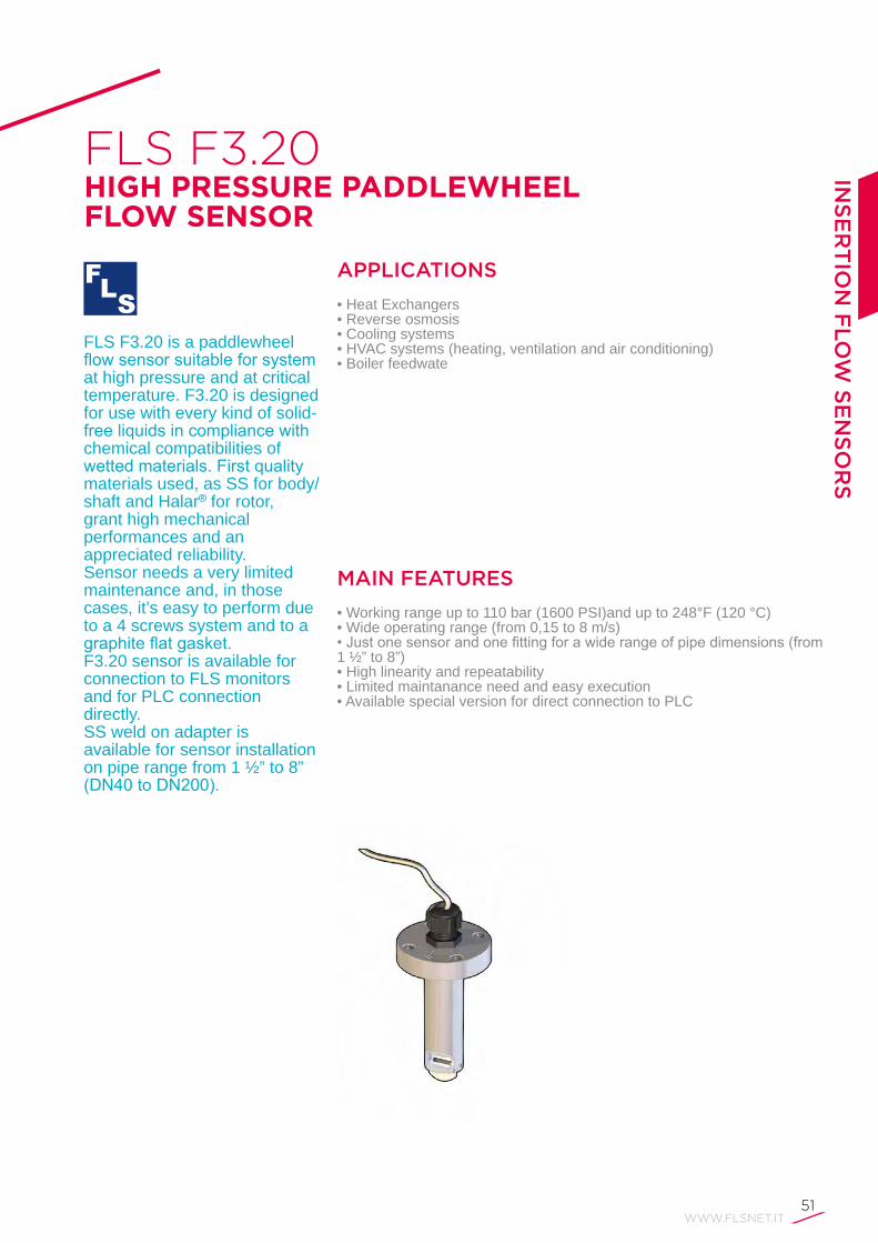
FLS F3.20HIGH PRESSURE PADDLEWHEEL FLOW SENSOR
MAIN FEATURES
• Working range up to 110 bar (1600 PSI)and up to 248°F (120 °C)• Wide operating range (from 0,15 to 8 m/s)•Justonesensorandonefittingforawiderangeofpipedimensions(from1 ½” to 8”)• High linearity and repeatability• Limited maintanance need and easy execution• Available special version for direct connection to PLC
APPLICATIONS
• Heat Exchangers• Reverse osmosis• Cooling systems• HVAC systems (heating, ventilation and air conditioning)• Boiler feedwate
FLS F3.20 is a paddlewheel flowsensorsuitableforsystemat high pressure and at critical temperature. F3.20 is designed for use with every kind of solid-freeliquidsincompliancewithchemical compatibilities of wettedmaterials.Firstqualitymaterials used, as SS for body/shaft and Halar® for rotor,grant high mechanical performances and an appreciated reliability. Sensor needs a very limited maintenance and, in those cases, it’s easy to perform due to a 4 screws system and to a graphiteflatgasket.F3.20 sensor is available for connection to FLS monitors and for PLC connection directly.SS weld on adapter is available for sensor installation on pipe range from 1 ½” to 8” (DN40toDN200).
52
TECHNICAL DATA
General•PipeSizeRange:DN40toDN200(0.5 to 8 in). Refer to Installation Fittings section for more details• Flow Rate Range: 0.15 to 8 m/s (0.5 to 25 ft./s)•Linearity:±0.75%offullscale•Repeatability:±0.5%offullscale• Pressure: 110 bar (1600 psi)• Temperature: 120 °C (248 °F)•MinimumReynoldsNumberRequired:4500• Enclosure: IP68• Wetted Materials:- sensor Body: 316L SS-sealingsystem:graphiteflatgasket- rotor: ECTFE (Halar®)- shaft: AISI316L
Specific for F3.20.H• Supply voltage: 5 to 24 VDC regulated• Supply current: < 30 mA @ 24 VDC• Output signal:-squarewave-frequency:45Hzperm/snominal(13.7Hzperft/snominal)-outputtype:transistorNPNopencollector- output current: 10 mA max• Cable length: 8 m (26.4 ft) standard,300 m (990 ft) maximum
Specific for F3.20.P• Supply voltage: 12 to 24 VDC regulated• Supply current: < 30 mA @ 24 VCC• Output signal:-squarewave-outputfrequency:45Hzperm/snominal(13.7Hzperft/s nominal)-outputtype:Push-Pull(digitalinputNPNorPNP)- output current: IOut max < 20 mA• Cable length: 8 m (26.4 ft) standard,300 m (990 ft) maximum
Standards & Approvals• Manufactured under ISO 9001 • Manufactured under ISO 14001 • CE• RoHS Compliant• EAC
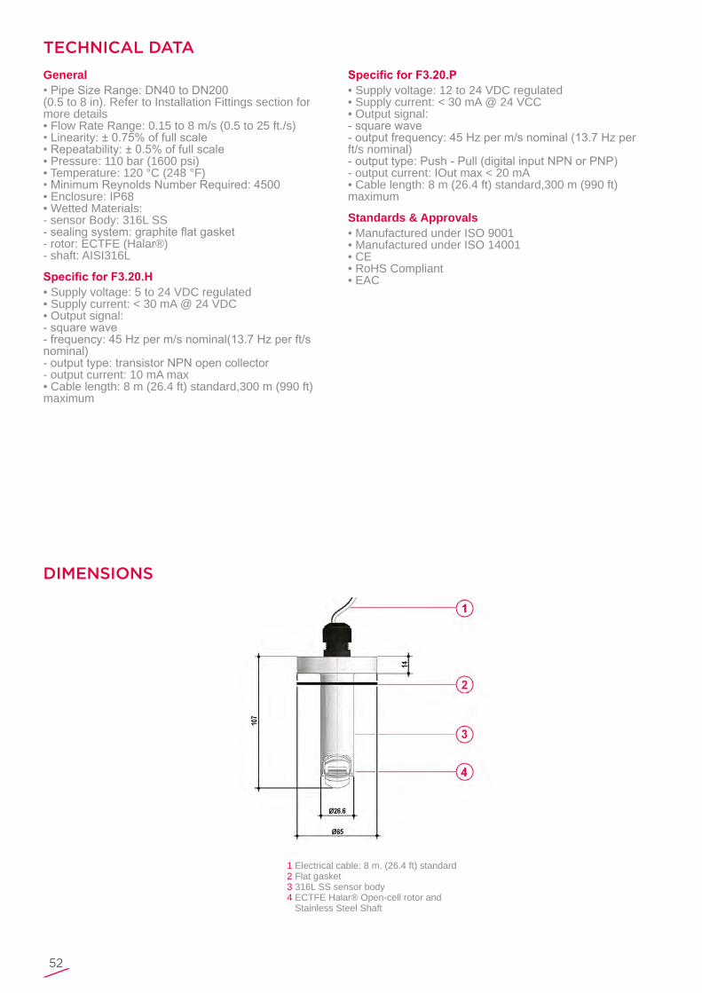
Electrical cable: 8 m. (26.4 ft) standard Flat gasket316L SS sensor bodyECTFE Halar® Open-cell rotor and Stainless Steel Shaft
1234
DIMENSIONS

WWW.FLSNET.IT53
INS
ER
TIO
N F
LO
W S
EN
SO
RS
F3.20 IP68 Sensor wiring connection
WIRING CONNECTIONS
ORDERING DATA
F3.20.X.01 High Pressure Paddlewheel Flow Sensors
Part No. VersionPower supply
LengthMain Wetted
MaterialsEnclosure Flow Rate Range
Weight (gr.)
F3.20.H.01 Hall 5- 24 VDC 107 mm 316L SS IP 68 0.15 to 8 m/s (0.5 to 25 ft./s) 600
F3.20.P.01 Push-Pull 12- 24 VDC 107 mm 316L SS IP 68 0.15 to 8 m/s (0.5 to 25 ft./s) 600

54
FLS F6.30 PADDLEWHEEL FLOW TRANSMITTER
MAIN FEATURES
• High chemical resistance•Pipesizerange:fromDN15(0,5”)toDN600(24”)• Low pressure drop• Friendly calibration procedure •4-20mA,frequencyorvolumetricpulseoutputsettablebyUSB• SSR settable as alarm by PC
APPLICATIONS
• Industrial water and wastewater treatment• Cooling water systems• Swimming pools• Flow control and monitoring• Water treatment• Water regeneration plant• Processing and manufacturing industry• Water distribution
The new FLS F6.30 is a blind transmitter based on paddlewheel. It can be applied for the measurement of every kindofsolid-freeliquids.TheF6.30canprovidesdifferentoutput options using a 4-20 mA and a Solid State Relay. Analog output can be used for long distance transmission and SSR can be set as an alarm or as a volumetric pulse output. F6.30 Paddlewheel Flow Transmitter is provided with an USB interface and a dedicated software (freely downloadable from FLS web site) which allows to easily calibrate instrument and to intuitively set outputs by a PC.Thespecificdesignallowsanaccurateflowmeasurementover a wide dynamic range in pipesizesfromDN15(0.5”)toDN600(24”).

WWW.FLSNET.IT55
INS
ER
TIO
N F
LO
W S
EN
SO
RS
TECHNICAL DATA
Maximum Operating Pressure / Temperature (25 years lifetime)F6.30 Transmitter • C-PVC body:- 10 bar (145 psi) @ 25°C (77°F)- 1,5 bar (22 psi) @ 80° C (176°F)• PVDF body:- 10 bar (145 psi) @ 25°C (77°F)- 2,5 bar (36 psi) @ 100°C (212°F)• SS body:- 25 bar (363 psi) @ 100°C (212°F)
General•PipeSizeRange:DN15toDN600(0.5”to24”)Please refer to Installation Fittings section for more details• Flow Rate Range: 0.15 to 8 m/s (0.5 to 25 ft./s)•Linearity:±0.75%offullscale•Repeatability:±0.5%offullscale•MinimumReynoldsNumberRequired:4500• Enclosure: IP65• Wetted Materials:- sensor Body: C-PVC, PVDF or 316L SS- o-rings: EPDM or FPM- rotor: ECTFE (Halar®)- shaft: Ceramic (Al2O3)/ 316L SS (only for metal sensors) - bearings: Ceramic (Al2O3)
Electrical• Power Supply:-12to24VDC±10%regulated(reversepolarityandshort circuit protected)- maximum current: consumption: 150 mA-protectiveearth:<10Ω•1XCurrentoutput:- 4-20 mA, isolated-max.loopimpedance:800Ω@24VDC-250Ω@12 VDC•1XSolidStateRelayoutput:-userselectableasMINalarm,MAXalarm,Volumetric,PulseOut,Windowalarm,Off-opticallyisolated,50mAMAXsink,24VDCMAXpull-up voltage- max pulse/min: 300- hysteresis: User selectable
Environmental• Storage Temperature: -30°C to +80°C (-22°F to176°F)• Ambient Temperature: -20°C to +70°C (-4°F to158°F)•RelativeHumidity:0to95%(non-condensing)
Standards & Approvals• Manufactured under ISO 9001 • Manufactured under ISO 14001 • CE• RoHS Compliant• EAC

56
DIMENSIONS
56ABScapforinstallationintofittingsElectronic box
1234
O-Ring (EPDM or FPM) Sensor body PVCC, PVDF, 316L SSHalar Rotor, Ceramic shaft & bearingsCable Gland
AB
Sensor bodyF6.30 Paddlewheel Flow Transmitter
Rear Terminal View
WIRING CONNECTIONS

WWW.FLSNET.IT57
INS
ER
TIO
N F
LO
W S
EN
SO
RS
ORDERING DATA
FLS F6.30.XX Paddlewheel Flow Transmitters
Part No. VersionPower supply
LengthMain wetted
materialsEnclosure Flow Rate Range
Weight (gr.)
F6.30.01 Hall 12 - 24 VDC L0 C-PVC/EPDM IP65 0.15 to 8 m/s (0.5 to 25 ft./s.) 750
F6.30.02 Hall 12 - 24 VDC L0 C-PVC/FPM IP65 0.15 to 8 m/s (0.5 to 25 ft./s.) 750
F6.30.03 Hall 12 - 24 VDC L1 C-PVC/EPDM IP65 0.15 to 8 m/s (0.5 to 25 ft./s.) 800
F6.30.04 Hall 12 - 24 VDC L1 C-PVC/FPM IP65 0.15 to 8 m/s (0.5 to 25 ft./s.) 800
F6.30.05 Hall 12 - 24 VDC L0 PVDF/EPDM IP65 0.15 to 8 m/s (0.5 to 25 ft./s.) 750
F6.30.06 Hall 12 - 24 VDC L0 PVDF/FPM IP65 0.15 to 8 m/s (0.5 to 25 ft./s.) 750
F6.30.07 Hall 12 - 24 VDC L1 PVDF/EPDM IP65 0.15 to 8 m/s (0.5 to 25 ft./s.) 800
F6.30.08 Hall 12 - 24 VDC L1 PVDF/FPM IP65 0.15 to 8 m/s (0.5 to 25 ft./s.) 800
F6.30.09 Hall 12 - 24 VDC L0 316SS/EPDM IP65 0.15 to 8 m/s (0.5 to 25 ft./s.) 950
F6.30.10 Hall 12 - 24 VDC L0 316SS/FPM IP65 0.15 to 8 m/s (0.5 to 25 ft./s.) 950
F6.30.11 Hall 12 - 24 VDC L1 316SS/EPDM IP65 0.15 to 8 m/s (0.5 to 25 ft./s.) 1000
F6.30.12 Hall 12 - 24 VDC L1 316SS/FPM IP65 0.15 to 8 m/s (0.5 to 25 ft./s.) 1000

58
FLS F3.10PADDLEWHEEL MINI FLOW SENSOR
MAIN FEATURES
• IP68 enclosure• ABS body with EPDM or FPM seal• ABS 4-blade paddlewheel (no bearings)• Mono-directional design• Installation on standard FIP tees•PVDFbodyversiononrequest
APPLICATIONS
• Water treatment• Filtration systems• Pure water production• Water monitoring• Fertigation
The simple and reliable paddlewheel technology has been moved into this MINIFLOWsensortypeFLSF3.10, designed for use with everykindofsolid-freeliquids.The sensor can measure flowfrom0.25m/s(0.8ft/s)producingafrequencyoutputsignal highly repeatable. A rugged construction and a proven technology guarantee exceptional performances with little or no maintenance required.Theverysmalldimension and a special design make it suitable for installation on FIP standard Tee-fittingsfromDN15toDN40(0.5 to 1.5 in.).
WWW.FLSNET.IT59
INS
ER
TIO
N F
LO
W S
EN
SO
RS
TECHNICAL DATA
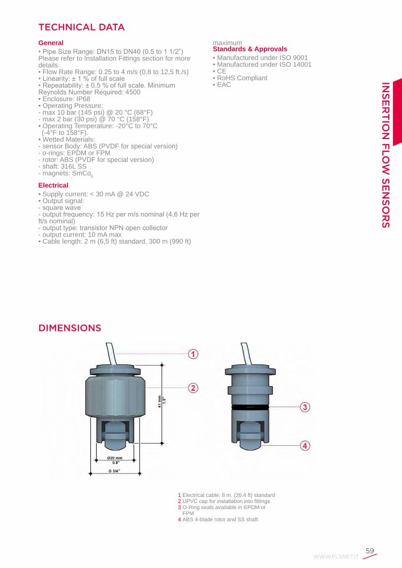
General•PipeSizeRange:DN15toDN40(0.5to11/2”)Please refer to Installation Fittings section for more details• Flow Rate Range: 0.25 to 4 m/s (0.8 to 12,5 ft./s)•Linearity:±1%offullscale•Repeatability:±0.5%offullscale.MinimumReynoldsNumberRequired:4500• Enclosure: IP68• Operating Pressure:- max 10 bar (145 psi) @ 20 °C (68°F)- max 2 bar (30 psi) @ 70 °C (158°F)• Operating Temperature: -20°C to 70°C (-4°F to 158°F).• Wetted Materials:- sensor Body: ABS (PVDF for special version)- o-rings: EPDM or FPM- rotor: ABS (PVDF for special version)- shaft: 316L SS- magnets: SmCo5
Electrical• Supply current: < 30 mA @ 24 VDC• Output signal:-squarewave-outputfrequency:15Hzperm/snominal(4,6Hzperft/s nominal)-outputtype:transistorNPNopencollector- output current: 10 mA max• Cable length: 2 m (6,5 ft) standard, 300 m (990 ft)
maximumStandards & Approvals• Manufactured under ISO 9001 • Manufactured under ISO 14001 • CE• RoHS Compliant• EAC
Electrical cable: 8 m. (26.4 ft) standardUPVCcapforinstallationintofittingsO-Ring seals available in EPDM or FPMABS 4-blade rotor and SS shaft
123
4
DIMENSIONS

60
F3.10 IP68 Sensor wiring connection
WIRING CONNECTIONS
ORDERING DATA
F3.10.H.XX Paddlewheel Miniflow Sensors
Part No. VersionPower supply
LengthMain wetted
materialsEnclosure Flow Rate Range
Weight (gr.)
F3.10.H.01 Hall 5 - 24 VDC 41 mm ABS/EPDM IP68 0.25 to 4 m/s (0.8 to 12,5 ft./s) 100
F3.10.H.02 Hall 5 - 24 VDC 41 mm ABS/FPM IP68 0.25 to 4 m/s (0.8 to 12,5 ft./s) 100

WWW.FLSNET.IT61
INS
ER
TIO
N F
LO
W S
EN
SO
RS
FLS F3.05PADDLEWHEEL FLOW SWITCH
MAIN FEATURES
• C-PVC, PVDF, Stainless Steel body• Easy insertion system• High chemical resistance•No-Flowalarmrelayoutput• Highly visible Local Bicolour Status lndicator• Maintenance free• Very low pressure drop
APPLICATIONS
• Pump protection• Filtration systems• Cooling water systemsThe simple insertion
paddlewheelflowswitchtype F3.05 is designed to protect a pump from running dry or pumping against a closedvalve.ltisequippedwith a mechanical SPST contact activated when the flowvelocitydropsbelowthe factory preset value of 0.15 m/s (0.5 ft/s). The F3.05 features a LED which shows theflowstatuslocally. A specially designed family of fittingensuresaneasyandquickinstallationintoallpipematerialsinsizesfromDN15toDN600(0.5”to24”).

62
TECHNICAL DATA
Maximum Operating Pressure / Temperature (25 years lifetime)F3.05 Sensor • C-PVC body:- 10 bar (145 psi) @ 25°C (77°F)- 1,5 bar (22 psi) @ 80° C (176°F)• PVDF body:- 10 bar (145 psi) @ 25°C (77°F)- 2,5 bar (36 psi) @ 100°C (212°F)• SS body:- 25 bar (363 psi) @ 120°C (248°F)
General•PipeSizeRange:DN15toDN600(0.5to24in.)Please refer to Installation Fittings section for more details•Supplyvoltage:12to24VDC±10%regulated• Supply current: < 50 mA• Relay Output: mechanical SPDT contact, 1A @ 24 VDC, 0.1A @ 230 VAC • Local Status Indicator: -GREENLed=Flow-REDLed=NoFlow•No-FlowRatePoint:0.15m/s(0.5ft./s)• Enclosure: IP65• Wetted Materials:- sensor Body: C-PVC or PVDF or 316L SS - o-rings: EPDM or FPM- rotor: ECTFE (Halar®) - shaft: Ceramic (Al2O3) - bearings: Ceramic (Al2O3)
Standards & Approvals• Manufactured under ISO 9001 • Manufactured under ISO 14001 • CE• RoHS Compliant• EAC

WWW.FLSNET.IT63
DIMENSIONS
5
678
C-PVC, PVDF or Stainless Steel sensor bodyECTFE (Halar®) Open-cell rotor,Ceramic shaftCeramic bearings
1
234
4polecableplugaccordingtoDlN43650-B/lSO 6952Local Bicolour Status LEDUPVCcapforinstallationintofittingsO-Ring seals available in EPDM or FPM
F3.05 sensor wiring connection
WIRING CONNECTIONS
INS
ER
TIO
N F
LO
W S
EN
SO
RS

64
ORDERING DATA
F3.05.XX Paddlewheel Flow Switches
Part No. VersionPower supply
LengthMain wetted
materialsEnclosure Flow Rate Range
Weight (gr.)
F3.05.01 Hall 12 to 24 VDC L0 C-PVC/EPDM lP65 - 250
F3.05.02 Hall 12 to 24 VDC L0 C-PVC/FPM lP65 - 250
F3.05.03 Hall 12 to 24 VDC L1 C-PVC/EPDM lP65 - 300
F3.05.04 Hall 12 to 24 VDC L1 C-PVC/FPM lP65 - 300
F3.05.05 Hall 12 to 24 VDC L0 PVDF/EPDM lP65 - 250
F3.05.06 Hall 12 to 24 VDC L0 PVDF/FPM lP65 - 250
F3.05.07 Hall 12 to 24 VDC L1 PVDF/EPDM lP65 - 300
F3.05.08 Hall 12 to 24 VDC L1 PVDF/FPM lP65 - 300
F3.05.09 Hall 12 to 24 VDC L0 316L SS/EPDM lP65 - 600
F3.05.10 Hall 12 to 24 VDC L0 316L SS/FPM lP65 - 600
F3.05.11 Hall 12 to 24 VDC L1 316L SS/EPDM lP65 - 650
F3.05.12 Hall 12 to 24 VDC L1 316L SS/FPM lP65 - 650

INSTALLATION & OPERATING GUIDELINES FOR INSERTION FLOW SENSORS

WWW.FLSNET.IT75
Insertion Technology Main Features
Flow Sensor Installation
Full Pipe Condition
Uniform Flow Velocity
•Alltheinsertiontechnologyflowsensorsarevelocity-basedflowmeasurement devices;•Theinstallationtypicallyrequiresonlyasmallholeinthepipeforsensorperpendicular mounting;•Sensorsdimensionarenotpipesizespecific:almostindependentfrompipe cross section.
Theplacementofaflowmeteriscriticaltogetanaccurateandreliablereading.Foraflowmeterproperperformanceitisnecessarytocheck:• Full pipe at every time;•Uniformflowvelocityintothepipe.
Ifthepipeisnotfulltheflowmeterwillgiveinaccuratereadingevenifthesensor is always completely submerged. Sensorwillmaketheflowratecalculationontheassumptionthatthepipeisfull,leadingtooverestimationoftheflow.Apumpintakeoranoutletonthe bottom of a tank does not necessary ensure the pipe always running full; air can be sucked by pumps or it could remain entrapped when the pipe was empty.Anywaytheflowmetershouldbealwayssituatedinthelowestpointofthepipeandthereshouldbedownstreamtheflowmeterapartofthepipeplaced1xIDhigherthanwheretheflowmeterislocated.
Insertionflowmetersmeasurethevelocityoftheliquid.Itisimportantthe velocity is uniform across the entire cross section of the pipe in the location of the sensor. Flow patterns are distorted both downstream and upstream of any disturbance.Inapipe,liquidattheedgeofthepipemovesslowerthantowardsthecenter because of friction along the walls.In a straight run of pipe, area with similar velocities can be depicted as concentric rings.
INSTALLATION GUIDELINESIN
SE
RT
ION
FLO
W S
EN
SO
RS
76
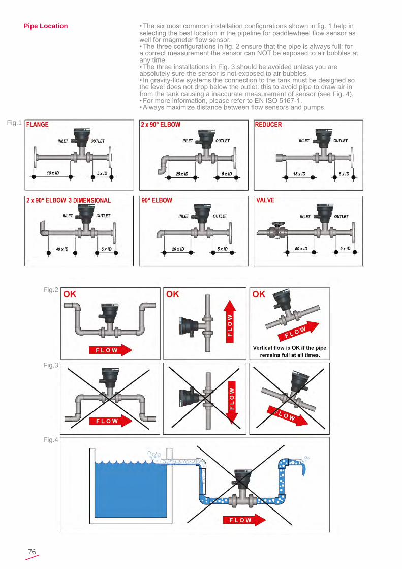
•Thesixmostcommoninstallationconfigurationsshowninfig.1helpinselectingthebestlocationinthepipelineforpaddlewheelflowsensoraswellformagmeterflowsensor.•Thethreeconfigurationsinfig.2ensurethatthepipeisalwaysfull:foracorrectmeasurementthesensorcanNOTbeexposedtoairbubblesatany time.• The three installations in Fig. 3 should be avoided unless you are absolutely sure the sensor is not exposed to air bubbles.•Ingravity-flowsystemstheconnectiontothetankmustbedesignedsothe level does not drop below the outlet: this to avoid pipe to draw air in from the tank causing a inaccurate measurement of sensor (see Fig. 4).•Formoreinformation,pleaserefertoENISO5167-1.•Alwaysmaximizedistancebetweenflowsensorsandpumps.
Pipe Location
Fig.1
Fig.2
Fig.3
Fig.4
WWW.FLSNET.IT77
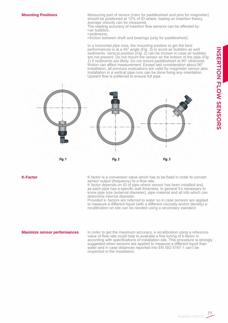
Mounting Positions Measuring part of sensor (rotor for paddlewheel and pins for magmeter) shouldbepositionedat12%ofIDwhere,basingoninsertiontheory,average velocity can be measured. Thereadingaccuracyofinsertionflowsensorscanbeaffectedby:• air bubbles;• sediments;• friction between shaft and bearings (only for paddlewheel).
In a horizontal pipe runs, the mounting position to get the best performances is at a 45° angle (Fig. 3) to avoid air bubbles as well sediments. Vertical position (Fig. 2) can be chosen in case air bubbles are not present. Do not mount the sensor on the bottom of the pipe (Fig. 1) if sediments are likely. Do not mount paddlewheel at 90° otherwise frictioncanaffectmeasurement.Exceptlastconsiderationabout90°installation, all previous evaluations are valid for magmeter sensor also.Installationinaverticalpiperunscanbedonefixinganyorientation.Upwardflowispreferredtoensurefullpipe.
K-Factor
Maximize sensor performances
Kfactorisaconversionvaluewhichhastobefixedinordertoconvertsensoroutput(frequency)toaflowrate.K factor depends on ID of pipe where sensor has been installed and, aseachpipehasaspecificwallthickness,ingeneralit’snecessarytoknow pipe size (external diameter), pipe material and all info which can determine internal diameter.Provided k- factors are referred to water so in case sensors are applied tomeasureadifferentliquid(withadifferentviscosityand/ordensity)arecalibration on-site can be needed using a secondary standard.
In order to get the maximum accuracy, a recalibration using a reference valueofflowratecouldhelptoevaluateafinetuningofk-factorinaccordingwithspecificationsofinstallationsite.ThisprocedureisstronglysuggestedwhensensorsareappliedtomeasureadifferentliquidthanwaterandincasedistancesreportedintoENISO5167-1can’tberespected in the installation.
INS
ER
TIO
N F
LO
W S
EN
SO
RS

78
Paddlewheel Flow Sensors
Magmeter Flow Sensor
Hot tap Insertion Flowmeters
Rotorandshaftareindirectcontactwiththefluid.Sincethepaddlewillspinatavelocitythatisdirectlyproportionaltotherateofflow,thesecomponents will wear over time. Rotors which have operated at high velocity will tend to wear more than units operated at low velocities. Becauseeveryfluidhasdifferentcharacteristics,itisdifficulttoestimatethe life expectancy of these components. The chemical compatibilities of each wetted component to the chemical being measured should be considered to choose the best material option. Axles and paddles can be easily replaceable in order to maintain better performances. Avoid using paddlewheelflowmetersformeasuringverydirtyfluid,orliquidswithrocksor pebbles that could break or damage the rotor or the axle. Solidscouldaffectsensorresponsealsomodifyingfrictionofshaft.Don’tusepaddlewheelincaseliquidcontainsfibers.A neglected paddlewheel will in time have degraded accuracy. Even if in caseliquidcontainssolidswesuggesttoapplyamagmeter,youcanusea paddlewheel but in such case it’s strongly suggested to plan a cleaning procedure of wetted parts periodically. For cleaning procedure use detergent or chemicals compatible with wetted materials.
Ingeneralmagmeterflowsensordoesn’tneedaspecificmaintenance.Incasemagmeterisusedtomeasureaverydirtyliquiditcanbesuggested to clean periodically the device with a cloth slightly dampened withwateroraliquidcompatiblewiththematerialsofthedeviceandcloth.Dirty electrodes may cause measurement inaccuracy. Do not use abrasive materials to take maintenance.
The use of hot tap instrumentation is suggested for installation in pressurizedpipesandwhenitisimpossibletostoptheflowrateintothepipeline.Hot tap version is available for magmeter, paddlewheel and turbine sensors.Previous advices are valid for these versions also.The sensors designed for hot tap installation are suitable also for pipes with a diameter larger than the maximum covered by traditional sensors (typicallyDN600/24”).Hottapsensorshavetobecombinedwithhottapfittingonly.
OPERATING GUIDELINES

INSTALLATION FITTINGS FOR FLOW SENSORS AND ANALYTICAL ELECTRODES

STANDARD INSERTION INSTALLATION
WWW.FLSNET.IT123
INS
TA
LL
AT
ION
FIT
TIN
GS
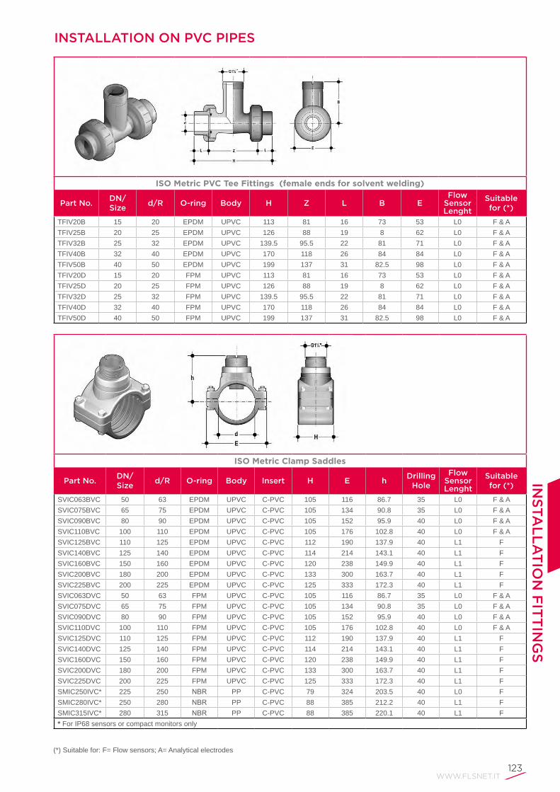
INSTALLATION ON PVC PIPES
ISO Metric PVC Tee Fittings (female ends for solvent welding)
Part No.DN/Size
d/R O-ring Body H Z L B EFlow
Sensor Lenght
Suitable for (*)
TFIV20B 15 20 EPDM UPVC 113 81 16 73 53 L0 F & A TFIV25B 20 25 EPDM UPVC 126 88 19 8 62 L0 F & A TFIV32B 25 32 EPDM UPVC 139.5 95.5 22 81 71 L0 F & A TFIV40B 32 40 EPDM UPVC 170 118 26 84 84 L0 F & A TFIV50B 40 50 EPDM UPVC 199 137 31 82.5 98 L0 F & A TFIV20D 15 20 FPM UPVC 113 81 16 73 53 L0 F & A TFIV25D 20 25 FPM UPVC 126 88 19 8 62 L0 F & A TFIV32D 25 32 FPM UPVC 139.5 95.5 22 81 71 L0 F & A TFIV40D 32 40 FPM UPVC 170 118 26 84 84 L0 F & A TFIV50D 40 50 FPM UPVC 199 137 31 82.5 98 L0 F & A
ISO Metric Clamp Saddles
Part No.DN/Size
d/R O-ring Body Insert H E hDrilling
Hole
Flow Sensor Lenght
Suitable for (*)
SVIC063BVC 50 63 EPDM UPVC C-PVC 105 116 86.7 35 L0 F & A SVIC075BVC 65 75 EPDM UPVC C-PVC 105 134 90.8 35 L0 F & A SVIC090BVC 80 90 EPDM UPVC C-PVC 105 152 95.9 40 L0 F & A SVIC110BVC 100 110 EPDM UPVC C-PVC 105 176 102.8 40 L0 F & A SVIC125BVC 110 125 EPDM UPVC C-PVC 112 190 137.9 40 L1 FSVIC140BVC 125 140 EPDM UPVC C-PVC 114 214 143.1 40 L1 FSVIC160BVC 150 160 EPDM UPVC C-PVC 120 238 149.9 40 L1 FSVIC200BVC 180 200 EPDM UPVC C-PVC 133 300 163.7 40 L1 FSVIC225BVC 200 225 EPDM UPVC C-PVC 125 333 172.3 40 L1 FSVIC063DVC 50 63 FPM UPVC C-PVC 105 116 86.7 35 L0 F & A SVIC075DVC 65 75 FPM UPVC C-PVC 105 134 90.8 35 L0 F & A SVIC090DVC 80 90 FPM UPVC C-PVC 105 152 95.9 40 L0 F & A SVIC110DVC 100 110 FPM UPVC C-PVC 105 176 102.8 40 L0 F & A SVIC125DVC 110 125 FPM UPVC C-PVC 112 190 137.9 40 L1 FSVIC140DVC 125 140 FPM UPVC C-PVC 114 214 143.1 40 L1 FSVIC160DVC 150 160 FPM UPVC C-PVC 120 238 149.9 40 L1 FSVIC200DVC 180 200 FPM UPVC C-PVC 133 300 163.7 40 L1 FSVIC225DVC 200 225 FPM UPVC C-PVC 125 333 172.3 40 L1 FSMIC250IVC* 225 250 NBR PP C-PVC 79 324 203.5 40 L0 FSMIC280IVC* 250 280 NBR PP C-PVC 88 385 212.2 40 L1 FSMIC315IVC* 280 315 NBR PP C-PVC 88 385 220.1 40 L1 F* For IP68 sensors or compact monitors only
(*) Suitable for: F= Flow sensors; A= Analytical electrodes

124
INSTALLATION ON PVC PIPES
(*) Suitable for: F= Flow sensors; A= Analytical electrodes
BSP Female Threaded PVC Tee Fittings (parallel threaded female ends)
Part No.DN/Size
d/R O-ring Body H Z L B EFlow
Sensor Lenght
Suitable for (*)
TFFV20B 15 1/2" EPDM UPVC 118.5 88.5 15 73 53 L0 F & A TFFV25B 20 3/4" EPDM UPVC 127.5 94.9 16.3 80 62 L0 F & A TFFV32B 25 1" EPDM UPVC 146 107.8 19.1 81 71 L0 F & A TFFV40B 32 1 1/4" EPDM UPVC 177 134.2 21.4 84 84 L0 F & A TFFV50B 40 1 1/2" EPDM UPVC 191 148.2 21.4 82.5 98 L0 F & A TFFV20D 15 1/2" FPM UPVC 118.5 88.5 15 73 53 L0 F & A TFFV25D 20 3/4" FPM UPVC 127.5 94.9 16.3 80 62 L0 F & A TFFV32D 25 1" FPM UPVC 146 107.8 19.1 81 71 L0 F & A TFFV40D 32 1 1/4" FPM UPVC 177 134.2 21.4 84 84 L0 F & A TFFV50D 40 1 1/2" FPM UPVC 191 148.2 21.4 82.5 98 L0 F & A
BS Solvent Welding PVC Tee Fittings (female ends for solvent welding)
Part No.DN/Size
d/R O-ring Body H Z L B EFlow
Sensor Lenght
Suitable for (*)
TFLV20B 15 1/2" EPDM UPVC 113 8 16.5 73 53 L0 F & A TFLV25B 20 3/4" EPDM UPVC 126 88 19 80 62 L0 F & A TFLV32B 25 1" EPDM UPVC 139.5 94.5 22.5 81 71 L0 F & A TFLV40B 32 1 1/4" EPDM UPVC 17 118 26 84 84 L0 F & A TFLV50B 40 1 1/2" EPDM UPVC 199 139 30 82.5 98 L0 F & A TFLV20D 15 1/2" FPM UPVC 113 8 16.5 73 53 L0 F & A TFLV25D 20 3/4" FPM UPVC 126 88 19 80 62 L0 F & A TFLV32D 25 1" FPM UPVC 139.5 94.5 22.5 81 71 L0 F & A TFLV40D 32 1 1/4" FPM UPVC 17 118 26 84 84 L0 F & A TFLV50D 40 1 1/2" FPM UPVC 199 139 30 82.5 98 L0 F & A

WWW.FLSNET.IT125
INS
TA
LL
AT
ION
FIT
TIN
GS
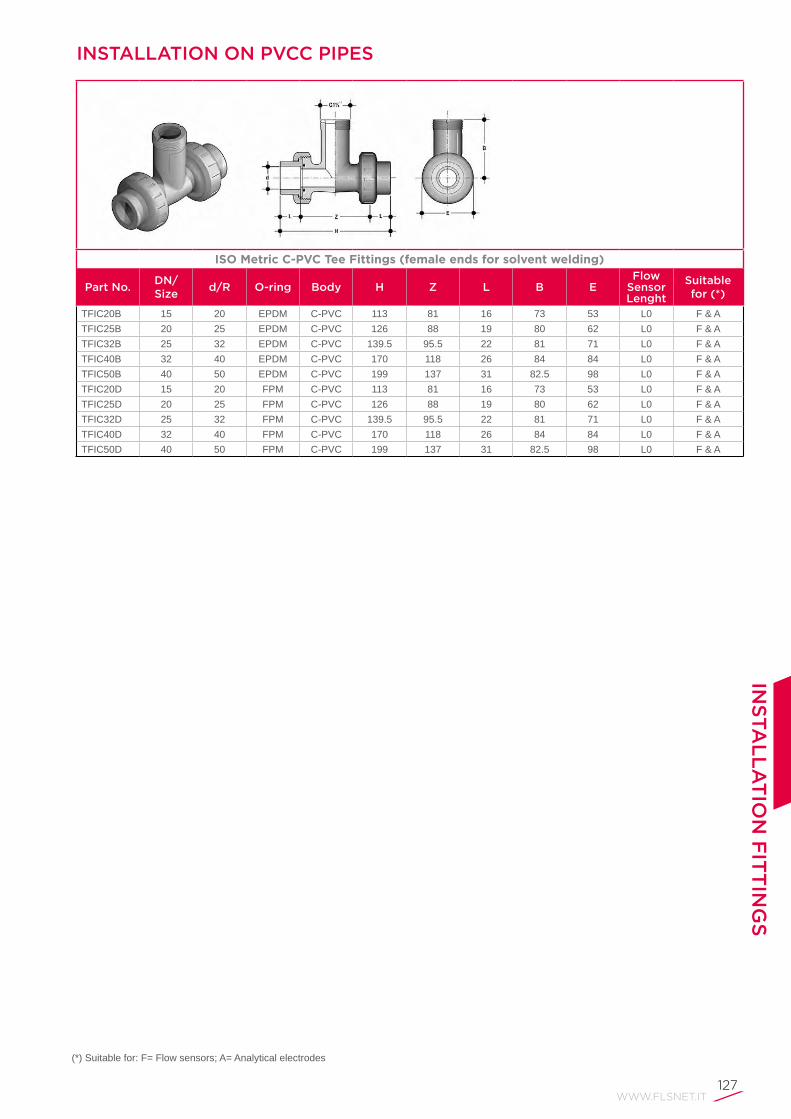
INSTALLATION ON PVC PIPES
BS Clamp Saddles
Part No.DN/Size
d/R O-ring Body Insert H E hDrilling
Hole
Flow Sensor Lenght
Suitable for (*)
SVLC2.0BVM 50 2" EPDM UPVC C-PVC 105 116 85.3 35 L0 F & A SVLC3.0BVM 80 3" EPDM UPVC C-PVC 105 152 95.0 40 L0 F & A SVLC4.0BVM 100 4" EPDM UPVC C-PVC 105 176 103.5 40 L0 F & A SVLC6.0BVM 150 6" EPDM UPVC C-PVC 120 238 151.7 40 L1 FSVLC8.0BVM 200 8" EPDM UPVC C-PVC 125 333 169.8 40 L1 FSVLC2.0DVM 50 2" FPM UPVC C-PVC 105 116 85.3 35 L0 F & A SVLC3.0DVM 80 3" FPM UPVC C-PVC 105 152 95.0 40 L0 F & A SVLC4.0DVM 100 4" FPM UPVC C-PVC 105 176 103.5 40 L0 F & A SVLC6.0DVM 150 6" FPM UPVC C-PVC 120 238 151.7 40 L1 FSVLC8.0DVM 200 8" FPM UPVC C-PVC 125 333 169.8 40 L1 F
(*) Suitable for: F= Flow sensors; A= Analytical electrodes
ASTM SCH. 80 PVC Tee Fittings (female ends for solvent welding)
Part No.DN/Size
d/R O-ring Body H Z L B EFlow
Sensor Lenght
Suitable for (*)
TFAV20B 15 1/2" EPDM UPVC 4.92" 3.15" 0.89" 2.87" 2.09" L0 F & A TFAV25B 20 3/4" EPDM UPVC 5.51" 3.50" 1.00" 3.15" 2.44" L0 F & A TFAV32B 25 1" EPDM UPVC 6.04" 3.78" 1.13" 3.19" 2.80" L0 F & A TFAV40B 32 1 1/4" EPDM UPVC 7.34" 4.80" 1.26" 3.31" 3.31" L0 F & A TFAV50B 40 1 1/2" EPDM UPVC 8.15" 5.39" 1.38" 3.25" 3.86" L0 F & A TFAV20D 15 1/2" FPM UPVC 4.92" 3.15" 0.89" 2.87" 2.09" L0 F & A TFAV25D 20 3/4" FPM UPVC 5.51" 3.50" 1.00" 3.15" 2.44" L0 F & A TFAV32D 25 1" FPM UPVC 6.04" 3.78" 1.13" 3.19" 2.80" L0 F & A TFAV40D 32 1 1/4" FPM UPVC 7.34" 4.80" 1.26" 3.31" 3.31" L0 F & A TFAV50D 40 1 1/2" FPM UPVC 8.15" 5.39" 1.38" 3.25" 3.86" L0 F & A

126
INSTALLATION ON PVC PIPES
NPT Female Threaded PVC Tee Fittings (NPT threaded female ends)
Part No.DN/Size
d/R O-ring Body H Z L B EFlow
Sensor Lenght
Suitable for (*)
TFNV20B 15 1/2" EPDM UPVC 4.67" 3.26" 0.70" 2.87" 2.09" L0 F & A TFNV25B 20 3/4" EPDM UPVC 5.02" 3.60" 0.71" 3.15" 2.44" L0 F & A TFNV32B 25 1" EPDM UPVC 5.75" 3.97" 0.89" 3.19" 2.80" L0 F & A TFNV40B 32 1 1/4" EPDM UPVC 6.97" 5.12" 0.93" 3.31" 3.31" L0 F & A TFNV50B 40 1 1/2" EPDM UPVC 7.52" 5.28" 1.12" 3.25" 3.86" L0 F & A TFNV20D 15 1/2" FPM UPVC 4.67" 3.26" 0.70" 2.87" 2.09" L0 F & A TFNV25D 20 3/4" FPM UPVC 5.02" 3.60" 0.71" 3.15" 2.44" L0 F & A TFNV32D 25 1" FPM UPVC 5.75" 3.97" 0.89" 3.19" 2.80" L0 F & A TFNV40D 32 1 1/4" FPM UPVC 6.97" 5.12" 0.93" 3.31" 3.31" L0 F & A TFNV50D 40 1 1/2" FPM UPVC 7.52" 5.28" 1.12" 3.25" 3.86" L0 F & A
(*) Suitable for: F= Flow sensors; A= Analytical electrodes
ASTM Clamp Saddles
Part No.DN/Size
d/R O-ring Body Insert H E hDrilling
Hole
Flow Sensor Lenght
Suitable for (*)
SVAC2.0BVM 50 2" EPDM UPVC C-PVC 4.13" 4.57" 3.3" 1.38" L0 F & A SVAC2.5BVM 65 2 1/2" EPDM UPVC C-PVC 4.13" 5.28" 3.4" 1.38" L0 F & A SVAC3.0BVM 80 3" EPDM UPVC C-PVC 4.13" 5.98" 3.6" 1.57" L0 F & A SVAC4.0BVM 100 4" EPDM UPVC C-PVC 4.13" 6.93" 4.0" 1.57" L0 F & A SVAC5.0BVM 125 5" EPDM UPVC C-PVC 4.49" 8.43" 5.6" 1.57" L1 FSVAC6.0BVM 150 6" EPDM UPVC C-PVC 4.72" 9.37" 5.9" 1.57" L1 FSVAC8.0BVM 200 8" EPDM UPVC C-PVC 4.92" 13.11" 6.6" 1.57" L1 FSVAC2.0DVM 50 2" FPM UPVC C-PVC 4.13" 4.57" 3.3" 1.38" L0 F & A SVAC2.5DVM 65 2 1/2" FPM UPVC C-PVC 4.13" 5.28" 3.4" 1.38" L0 F & A SVAC3.0DVM 80 3" FPM UPVC C-PVC 4.13" 5.98" 3.6" 1.57" L0 F & A SVAC4.0DVM 100 4" FPM UPVC C-PVC 4.13" 6.93" 4.0" 1.57" L0 F & A SVAC5.0DVM 125 5" FPM UPVC C-PVC 4.49" 8.43" 5.6" 1.57" L1 FSVAC6.0DVM 150 6" FPM UPVC C-PVC 4.72" 9.37" 5.9" 1.57" L1 FSVAC8.0DVM 200 8" FPM UPVC C-PVC 4.92" 13.11" 6.6" 1.57" L1 F
WWW.FLSNET.IT127
INS
TA
LL
AT
ION
FIT
TIN
GS
ISO Metric C-PVC Tee Fittings (female ends for solvent welding)
Part No.DN/Size
d/R O-ring Body H Z L B EFlow
Sensor Lenght
Suitable for (*)
TFIC20B 15 20 EPDM C-PVC 113 81 16 73 53 L0 F & ATFIC25B 20 25 EPDM C-PVC 126 88 19 80 62 L0 F & ATFIC32B 25 32 EPDM C-PVC 139.5 95.5 22 81 71 L0 F & ATFIC40B 32 40 EPDM C-PVC 170 118 26 84 84 L0 F & ATFIC50B 40 50 EPDM C-PVC 199 137 31 82.5 98 L0 F & ATFIC20D 15 20 FPM C-PVC 113 81 16 73 53 L0 F & ATFIC25D 20 25 FPM C-PVC 126 88 19 80 62 L0 F & ATFIC32D 25 32 FPM C-PVC 139.5 95.5 22 81 71 L0 F & ATFIC40D 32 40 FPM C-PVC 170 118 26 84 84 L0 F & ATFIC50D 40 50 FPM C-PVC 199 137 31 82.5 98 L0 F & A
(*) Suitable for: F= Flow sensors; A= Analytical electrodes
INSTALLATION ON PVCC PIPES

128
INSTALLATION ON PVCC PIPES
ISO Metric Clamp Saddles
Part No.DN/Size
d/R O-ring Body Insert H E hDrilling
Hole
Flow Sensor Lenght
Suitable for (*)
SVIC063BVC 50 63 EPDM UPVC C-PVC 105 116 86.7 35 L0 F & A SVIC075BVC 65 75 EPDM UPVC C-PVC 105 134 90.8 35 L0 F & A SVIC090BVC 80 90 EPDM UPVC C-PVC 105 152 95.9 40 L0 F & A SVIC110BVC 100 110 EPDM UPVC C-PVC 105 176 102.8 40 L0 F & A SVIC125BVC 110 125 EPDM UPVC C-PVC 112 190 137.9 40 L1 FSVIC140BVC 125 140 EPDM UPVC C-PVC 114 214 143.1 40 L1 FSVIC160BVC 150 160 EPDM UPVC C-PVC 120 238 149.9 40 L1 FSVIC200BVC 180 200 EPDM UPVC C-PVC 133 300 163.7 40 L1 FSVIC225BVC 200 225 EPDM UPVC C-PVC 125 333 172.3 40 L1 FSVIC063DVC 50 63 FPM UPVC C-PVC 105 116 86.7 35 L0 F & A SVIC075DVC 65 75 FPM UPVC C-PVC 105 134 90.8 35 L0 F & A SVIC090DVC 80 90 FPM UPVC C-PVC 105 152 95.9 40 L0 F & A SVIC110DVC 100 110 FPM UPVC C-PVC 105 176 102.8 40 L0 F & A SVIC125DVC 110 125 FPM UPVC C-PVC 112 190 137.9 40 L1 FSVIC140DVC 125 140 FPM UPVC C-PVC 114 214 143.1 40 L1 FSVIC160DVC 150 160 FPM UPVC C-PVC 120 238 149.9 40 L1 FSVIC200DVC 180 200 FPM UPVC C-PVC 133 300 163.7 40 L1 FSVIC225DVC 200 225 FPM UPVC C-PVC 125 333 172.3 40 L1 FSMIC250IVC* 225 250 NBR PP C-PVC 79 324 203.5 40 L0 FSMIC280IVC* 250 280 NBR PP C-PVC 88 385 212.2 40 L1 FSMIC315IVC* 280 315 NBR PP C-PVC 88 385 220.1 40 L1 F * For IP68 sensors or compact monitors only
(*) Suitable for: F= Flow sensors; A= Analytical electrodes

WWW.FLSNET.IT129
INSTALLATION ON PP PIPES
ISO Metric PP Tee Fittings (female ends for socket welding)
Part No.DN/Size
d/R O-ring Body H Z L B EFlow
Sensor Lenght
Suitable for (*)
TFIM20B 15 20 EPDM PP 111 73 14.5 73 53 L0 F & ATFIM25B 20 25 EPDM PP 120.5 80 16 80 62 L0 F & ATFIM32B 25 32 EPDM PP 133.5 81 18 81 71 L0 F & ATFIM40B 32 40 EPDM PP 163.5 84 20.5 84 84 L0 F & ATFIM50B 40 50 EPDM PP 195 82.5 23.5 82.5 98 L0 F & ATFIM20D 15 20 FPM PP 111 73 14.5 73 53 L0 F & ATFIM25D 20 25 FPM PP 120.5 80 16 80 62 L0 F & ATFIM32D 25 32 FPM PP 133.5 81 18 81 71 L0 F & ATFIM40D 32 40 FPM PP 163.5 84 20.5 84 84 L0 F & ATFIM50D 40 50 FPM PP 195 82.5 23.5 82.5 98 L0 F & A
BSP Female Threaded PP Tee Fittings (parallel threaded female ends)
Part No.DN/Size
d/R O-ring Body H Z L B EFlow
Sensor Lenght
Suitable for (*)
TFFM20B 15 1/2" EPDM PP 113 83 15 73 53 L0 F & ATFFM25B 20 3/4" EPDM PP 126 93.4 16.3 80 62 L0 F & ATFFM32B 25 1" EPDM PP 139.5 101.3 19.1 81 71 L0 F & ATFFM40B 32 1 1/4" EPDM PP 17 127.2 21.4 84 84 L0 F & ATFFM50B 40 1 1/2" EPDM PP 199 156.2 21.4 82.5 98 L0 F & ATFFM20D 15 1/2" FPM PP 113 83 15 73 53 L0 F & ATFFM25D 20 3/4" FPM PP 126 93.4 16.3 80 62 L0 F & ATFFM32D 25 1" FPM PP 139.5 101.3 19.1 81 71 L0 F & ATFFM40D 32 1 1/4" FPM PP 17 127.2 21.4 84 84 L0 F & ATFFM50D 40 1 1/2" FPM PP 199 156.2 21.4 82.5 98 L0 F & A
INS
TA
LL
AT
ION
FIT
TIN
GS
(*) Suitable for: F= Flow sensors; A= Analytical electrodes

130
(*) Suitable for: F= Flow sensors; A= Analytical electrodes
INSTALLATION ON PP PIPES
ISO metric Clamp Saddles
Part No.DN/Size
d/R O-ring Body Insert H E hDrilling
Hole
Flow Sensor Lenght
Suitable for (*)
SVIC063BME 50 63 EPDM UPVC C-PVC ** 105 116 84.3 35 L0 F & A SVIC075BME 65 75 EPDM UPVC C-PVC ** 105 134 88. 35 L0 F & A SVIC090BME 80 90 EPDM UPVC C-PVC ** 105 152 92.6 4 L0 F & A SVIC110BME 100 110 EPDM UPVC C-PVC ** 105 176 98.8 40 L0 F & A SVIC125BME 110 125 EPDM UPVC C-PVC ** 112 190 133.3 40 L1 FSVIC140BME 125 140 EPDM UPVC C-PVC ** 114 214 138.0 40 L1 FSVIC160BME 150 160 EPDM UPVC C-PVC ** 120 238 144.1 40 L1 FSVIC200BME 180 200 EPDM UPVC C-PVC ** 133 300 156.4 40 L1 FSVIC225BME 200 225 EPDM UPVC C-PVC ** 125 333 164.1 40 L1 FSVIC063DME 50 63 FPM UPVC C-PVC ** 105 116 84.3 35 L0 F & A SVIC075DME 65 75 FPM UPVC C-PVC ** 105 134 88. 35 L0 F & A SVIC090DME 80 90 FPM UPVC C-PVC ** 105 152 92.6 4 L0 F & A SVIC110DME 100 110 FPM UPVC C-PVC ** 105 176 98.8 40 L0 F & A SVIC125DME 110 125 FPM UPVC C-PVC ** 112 190 133.3 40 L1 FSVIC140DME 125 140 FPM UPVC C-PVC ** 114 214 138.0 40 L1 FSVIC160DME 150 160 FPM UPVC C-PVC ** 120 238 144.1 40 L1 FSVIC200DME 180 200 FPM UPVC C-PVC ** 133 300 156.4 40 L1 FSVIC225DME 200 225 FPM UPVC C-PVC ** 125 333 164.1 40 L1 FSMIC250IME* 225 250 NBR PP C-PVC ** 79 324 189.9 40 L0 FSMIC280IME* 250 280 NBR PP C-PVC ** 88 385 200.2 40 L1 FSMIC315IME* 300 315 NBR PP C-PVC ** 88 385 209.3 40 L1 F*ForIP68sensorsorcompactmonitorsonly**PVDFinsertavailableonrequest
NPT Female Threaded PP Tee Fittings (NPT threaded female ends)
Part No.DN/Size
d/R O-ring Body H Z L B EFlow
Sensor Lenght
Suitable for (*)
TFNM20B 15 1/2" EPDM PP 4.45" 3.05" 0.70" 2.87" 2.09" L0 F & ATFNM25B 20 3/4" EPDM PP 4.96" 3.54" 0.71" 3.15" 2.44" L0 F & ATFNM32B 25 1" EPDM PP 5.49" 3.71" 0.89" 3.19" 2.80" L0 F & ATFNM40B 32 1 1/4" EPDM PP 6.69" 4.84" 0.93" 3.31" 3.31" L0 F & ATFNM50B 40 1 1/2" EPDM PP 7.83" 5.59" 1.12" 3.25" 3.86" L0 F & ATFNM20D 15 1/2" FPM PP 4.45" 3.05" 0.70" 2.87" 2.09" L0 F & ATFNM25D 20 3/4" FPM PP 4.96" 3.54" 0.71" 3.15" 2.44" L0 F & ATFNM32D 25 1" FPM PP 5.49" 3.71" 0.89" 3.19" 2.80" L0 F & ATFNM40D 32 1 1/4" FPM PP 6.69" 4.84" 0.93" 3.31" 3.31" L0 F & ATFNM50D 40 1 1/2" FPM PP 7.83" 5.59" 1.12" 3.25" 3.86" L0 F & A

WWW.FLSNET.IT131
INS
TA
LL
AT
ION
FIT
TIN
GS
(*) Suitable for: F= Flow sensors; A= Analytical electrodes
ASTM Clamp Saddles
Part No.DN/Size
d/R O-ring Body Insert H E hDrilling
Hole
Flow Sensor Lenght
Suitable for (*)
SVAC2.0BVM 50 2" EPDM UPVC C-PVC** 4.13" 4.57" 3.29" 1.38" L0 F & A SVAC2.5BVM 65 2 1/2" EPDM UPVC C-PVC** 4.13" 5.28" 3.43" 1.38" L0 F & A SVAC3.0BVM 80 3" EPDM UPVC C-PVC** 4.13" 5.98" 3.65" 1.57" L0 F & A SVAC4.0BVM 100 4" EPDM UPVC C-PVC** 4.13" 6.93" 4.00" 1.57" L0 F & A SVAC5.0BVM 125 5" EPDM UPVC C-PVC** 4.49" 8.43" 5.55" 1.57" L1 FSVAC6.0BVM 150 6" EPDM UPVC C-PVC** 4.72" 9.37" 5.91" 1.57" L1 FSVAC8.0BVM 200 8" EPDM UPVC C-PVC** 4.92" 13.11" 6.61" 1.57" L1 FSVAC2.0DVM 50 2" FPM UPVC C-PVC** 4.13" 4.57" 3.29" 1.38" L0 F & A SVAC2.5DVM 65 2 1/2" FPM UPVC C-PVC** 4.13" 5.28" 3.43" 1.38" L0 F & A SVAC3.0DVM 80 3" FPM UPVC C-PVC** 4.13" 5.98" 3.65" 1.57" L0 F & A SVAC4.0DVM 100 4" FPM UPVC C-PVC** 4.13" 6.93" 4.00" 1.57" L0 F & A SVAC5.0DVM 125 5" FPM UPVC C-PVC** 4.49" 8.43" 5.55" 1.57" L1 FSVAC6.0DVM 150 6" FPM UPVC C-PVC** 4.72" 9.37" 5.91" 1.57" L1 FSVAC8.0DVM 200 8" FPM UPVC C-PVC** 4.92" 13.11" 6.61" 1.57" L1 F**PVDFinsertavailableonrequest
INSTALLATION ON PP PIPES

132
INSTALLATION ON PVDF PIPES
ISO Metric PVDF Tee Fittings (female ends tor socket welding)
Part No.DN/Size
d/R O-ring Body H Z L B EFlow
Sensor Lenght
Suitable for (*)
TFIF20B 15 20 EPDM PVDF 111 82 14.5 73 53 L0 F & ATFIF25B 20 25 EPDM PVDF 120.5 88.5 16 80 62 L0 F & ATFIF32B 25 32 EPDM PVDF 133.5 97 18 81 71 L0 F & ATFIF40B 32 40 EPDM PVDF 161.5 120.5 20.5 84 84 L0 F & ATFIF50B 40 50 EPDM PVDF 193.5 146.5 23.5 82.5 98 L0 F & ATFIF20D 15 20 FPM PVDF 111 82 14.5 73 53 L0 F & ATFIF25D 20 25 FPM PVDF 120.5 88.5 16 80 62 L0 F & ATFIF32D 25 32 FPM PVDF 133.5 97 18 81 71 L0 F & ATFIF40D 32 40 FPM PVDF 161.5 120.5 20.5 84 84 L0 F & ATFIF50D 40 50 FPM PVDF 193.5 146.5 23.5 82.5 98 L0 F & A
ISO Metric Clamp Saddles
Part No.DN/Size
d/R O-ring Body Insert H E hDrilling
Hole
Flow Sensor Lenght
Suitable for (*)
SVIF063BF 50 63 EPDM UPVC PVDF 105 116 87.2 35 L0 F & A SVIF075BF 65 75 EPDM UPVC PVDF 105 134 91.5 35 L0 F & A SVIF090BF 80 90 EPDM UPVC PVDF 105 152 96.8 40 L0 F & A SVIF110BF 100 110 EPDM UPVC PVDF 105 176 104.0 40 L0 F & A SVIF125BF 110 125 EPDM UPVC PVDF 112 190 139.3 40 L1 FSVIF140BF 125 140 EPDM UPVC PVDF 114 214 144.6 40 L1 FSVIF160BF 150 160 EPDM UPVC PVDF 120 238 151.8 40 L1 FSVIF200BF 180 200 EPDM UPVC PVDF 133 300 165.9 40 L1 FSVIF225BF 200 225 EPDM UPVC PVDF 125 333 174.9 40 L1 FSVIF063DF 50 63 FPM UPVC PVDF 105 116 87.2 35 L0 F & A SVIF075DF 65 75 FPM UPVC PVDF 105 134 91.5 35 L0 F & A SVIF090DF 80 90 FPM UPVC PVDF 105 152 96.8 40 L0 F & A SVIF110DF 100 110 FPM UPVC PVDF 105 176 104.0 40 L0 F & A SVIF125DF 110 125 FPM UPVC PVDF 112 190 139.3 40 L1 FSVIF140DF 125 140 FPM UPVC PVDF 114 214 144.6 40 L1 FSVIF160DF 150 160 FPM UPVC PVDF 120 238 151.8 40 L1 FSVIF200DF 180 200 FPM UPVC PVDF 133 300 165.9 40 L1 FSVIF225DF 200 225 FPM UPVC PVDF 125 333 174.9 40 L1 F
(*) Suitable for: F= Flow sensors; A= Analytical electrodes

WWW.FLSNET.IT133
INSTALLATION ON PE PIPES
ISO Metric PVC Tee Fittings (PE end connectors for electrotusion or butt welding)
Part No.DN/Size
d/R O-ring Body H Z L B EFlow
Sensor Lenght
Suitable for (*)
TFIV20BE 15 20 EPDM UPVC 183 73 55 73 53 L0 F & ATFIV25BE 20 25 EPDM UPVC 223 83 70 80 62 L0 F & ATFIV32BE 25 32 EPDM UPVC 237 89 74 81 71 L0 F & ATFIV40BE 32 40 EPDM UPVC 266 110 78 84 84 L0 F & ATFIV50BE 40 50 EPDM UPVC 295 127 84 82.5 98 L0 F & ATFIV20DE 15 20 FPM UPVC 183 73 55 73 53 L0 F & ATFIV25DE 20 25 FPM UPVC 223 83 70 80 62 L0 F & ATFIV32DE 25 32 FPM UPVC 237 89 74 81 71 L0 F & ATFIV40DE 32 40 FPM UPVC 266 110 78 84 84 L0 F & ATFIV50DE 40 50 FPM UPVC 295 127 84 82.5 98 L0 F & A
(*) Suitable for: F= Flow sensors; A= Analytical electrodes
INS
TA
LL
AT
ION
FIT
TIN
GS
ISO Metric Clamp Saddles
Part No.DN/Size
d/R O-ring Body Insert H E hDrilling
Hole
Flow Sensor Lenght
Suitable for (*)
SVIC063BME 50 63 EPDM UPVC C-PVC 105 116 84.3 35 L0 F & A SVIC075BME 65 75 EPDM UPVC C-PVC 105 134 88. 35 L0 F & A SVIC090BME 80 90 EPDM UPVC C-PVC 105 152 92.6 4 L0 F & A SVIC110BME 100 110 EPDM UPVC C-PVC 105 176 98.8 40 L0 F & A SVIC125BME 110 125 EPDM UPVC C-PVC 112 190 133.3 40 L1 FSVIC140BME 125 140 EPDM UPVC C-PVC 114 214 138.0 40 L1 FSVIC160BME 150 160 EPDM UPVC C-PVC 120 238 144.1 40 L1 FSVIC200BME 180 200 EPDM UPVC C-PVC 133 300 156.4 40 L1 FSVIC225BME 200 225 EPDM UPVC C-PVC 125 333 164.1 40 L1 FSVIC063DME 50 63 FPM UPVC C-PVC 105 116 84.3 35 L0 F & A SVIC075DME 65 75 FPM UPVC C-PVC 105 134 88. 35 L0 F & A SVIC090DME 80 90 FPM UPVC C-PVC 105 152 92.6 4 L0 F & A SVIC110DME 100 110 FPM UPVC C-PVC 105 176 98.8 40 L0 F & A SVIC125DME 110 125 FPM UPVC C-PVC 112 190 133.3 40 L1 FSVIC140DME 125 140 FPM UPVC C-PVC 114 214 138.0 40 L1 FSVIC160DME 150 160 FPM UPVC C-PVC 120 238 144.1 40 L1 FSVIC200DME 180 200 FPM UPVC C-PVC 133 300 156.4 40 L1 FSVIC225DME 200 225 FPM UPVC C-PVC 125 333 164.1 40 L1 FSMIC250IME* 225 250 NBR PP C-PVC 79 324 189.9 40 L0 FSMIC280IME* 250 280 NBR PP C-PVC 88 385 200.2 40 L1 FSMIC315IME* 300 315 NBR PP C-PVC 88 385 209.3 40 L1 F* For IP68 sensors or compact monitors only

134
(*) Suitable for: F= Flow sensors; A= Analytical electrodes
(*) For IP68 sensors or compact monitors only
INSTALLATION ON METAL PIPES
BSP Female Threaded 316 SS Tee Fittings
Part No.DN/Size
d/R O-ring Body H Z L B EFlow
Sensor Lenght
Suitable for (*)
TFFX20 15 1/2" - 316 SS 85 - 16 73 42 L0 F & ATFFX25 20 3/4" - 316 SS 95 - 20 81.2 42 L0 F & ATFFX32 25 1" - 316 SS 105 - 22.5 81.2 42 L0 F & ATFFX40 32 1 1/4" - 316 SS 12 - 20.5 83.8 54 L0 F & A
Strap-on Saddles
Part No.DN/Size
O.D. min.
O.D. max
Parallel Thread (GAS)
O-ring Body Insert hDrilling
Hole
Flow Sensor Lenght
Suitable for (*)
SZIC080I* 80 88 104 1 1/4” EPDM Cast iron + SS C-PVC 153 40 L0 FSZIC100I* 100 112 126 1 1/4” EPDM Cast iron + SS C-PVC 160 40 L0 FSZIC125I* 125 140 154 1 1/4” EPDM Cast iron + SS C-PVC 170 40 L0 FSZIC150I* 150 168 184 1 1/4” EPDM Cast iron + SS C-PVC 180 40 L0 FSZIC200I* 200 218 234 1 1/4” EPDM Cast iron + SS C-PVC 228 40 L1 FSZIC250I* 250 272 286 1 1/4” EPDM Cast iron + SS C-PVC 247 40 L1 FSZIC300I* 300 322 344 1 1/4” EPDM Cast iron + SS C-PVC 266 40 L1 FSZIC350I* 350 356 384 1 1/4” EPDM Cast iron + SS C-PVC 305 40 L1 FSZIC400I* 400 425 458 1 1/4” EPDM Cast iron + SS C-PVC 324 40 L1 FSZIC450I* 450 475 516 1 1/4” EPDM Cast iron + SS C-PVC 343 40 L1 F

WWW.FLSNET.IT135
(*) Suitable for: F= Flow sensors; A= Analytical electrodes
INS
TA
LL
AT
ION
FIT
TIN
GS
316L SS Weld on Adapters
Part No. DN/Size d/RParallel Thread (GAS)
Body L D1 D2Drilling
Hole
Flow Sensor Lenght
Suitable for (*)
WAIXL0 40 - 1 1/4” 316L SS 68.5 33,9 34 34 L0 F & A WAIXL0 50 - 1 1/4” 316L SS 68.5 33,9 44 44 L0 F & A WAIXL0 60 - 1 1/4” 316L SS 68.5 33,9 44 44 L0 F & A WAIXL0 65 - 1 1/4” 316L SS 68.5 33,9 44 44 L0 F & A WAIXL0 80 - 1 1/4” 316L SS 68.5 33,9 44 44 L0 F & A WAIXL0 100 - 1 1/4” 316L SS 68.5 33,9 44 44 L0 F & A WAIXL0 110 - 1 1/4” 316L SS 68.5 33,9 44 44 L0 F & A WAIXL0 125 - 1 1/4” 316L SS 68.5 33,9 44 44 L0 F WAIXL0 150 - 1 1/4” 316L SS 68.5 33,9 44 44 L0 FWAIXL0 175 - 1 1/4” 316L SS 68.5 33,9 44 44 L0 F WAIXL0 200 - 1 1/4” 316L SS 68.5 33,9 44 44 L0 FWAIXL0 225 - 1 1/4” 316L SS 68.5 33,9 44 44 L0 FWAIXL1 250 - 1 1/4” 316L SS 98.5 33,9 44 44 L1 FWAIXL1 300 - 1 1/4” 316L SS 98.5 33,9 44 44 L1 FWAIXL1 350 - 1 1/4” 316L SS 98.5 33,9 44 44 L1 FWAIXL1 400 - 1 1/4” 316L SS 98.5 33,9 44 44 L1 FWAIXL1 450 - 1 1/4” 316L SS 98.5 33,9 44 44 L1 FWAIXL1 500 - 1 1/4” 316L SS 98.5 33,9 44 44 L1 FWAIXL1 600 - 1 1/4” 316L SS 98.5 33,9 44 44 L1 F
INSTALLATION ON METAL PIPES

136
(*) Suitable for: F= Flow sensors; A= Analytical electrodes
INSTALLATION FITTINGS FOR FLS F3.10
ISO Metric PVC Tee Fittings (female ends for solvent welding)
Part No.DN/Size
d/R O-ring Body H Z L B EFlow
Sensor Lenght
Suitable for (*)
TMIV20MF 15 20 - UPVC 43 11 16 27 27 - FTMIV25MF 20 25 - UPVC 52 14 19 30 33 - FTMIV32MF 25 32 - UPVC 61,5 17,5 22 33,5 41 - FTMIV40MF 32 40 - UPVC 74 22 26 38 50 - FTMIV50MF 40 50 - UPVC 89 27 31 43 61 - F
ISO Metric BRASS Tee Fitting (1 1/4” male threaded ends)
Part No.DN/Size
d/R O-ring Body H Z L B EFlow
Sensor Lenght
Suitable for (*)
TMFODN23 23 1 1/4" - BRASS 74,2 46,2 14 28 50 - F

WWW.FLSNET.IT137
(*) Suitable for: F= Flow sensors; A= Analytical electrodes
INS
TA
LL
AT
ION
FIT
TIN
GS
INSTALLATION FITTINGS FOR FLS F3.20
316L SS Weld-on Adapters
Part No. DN/Size d/RParallel Thread (GAS)
Body L D1 D2Drilling
Hole
Flow Sensor Lenght
Suitable for (*)
WAIXHP 40 - 1 1/4” 316L SS 68,5 34 42,8 34 L0 FWAIXHP 50 - 1 1/4” 316L SS 68,5 34 42,8 43 L0 FWAIXHP 60 - 1 1/4” 316L SS 68,5 34 42,8 43 L0 FWAIXHP 65 - 1 1/4” 316L SS 68,5 34 42,8 43 L0 FWAIXHP 80 - 1 1/4” 316L SS 68,5 34 42,8 43 L0 FWAIXHP 100 - 1 1/4” 316L SS 68,5 34 42,8 43 L0 FWAIXHP 110 - 1 1/4” 316L SS 68,5 34 42,8 43 L0 FWAIXHP 125 - 1 1/4” 316L SS 68,5 34 42,8 43 L0 FWAIXHP 150 - 1 1/4” 316L SS 68,5 34 42,8 43 L0 FWAIXHP 175 - 1 1/4” 316L SS 68,5 34 42,8 43 L0 FWAIXHP 200 - 1 1/4” 316L SS 68,5 34 42,8 43 L0 F

SPARE PARTS AND ACCESSORIESFOR MONITORS, FLOW SENSORS AND ANALYTICAL ELECTRODES

TECHNICAL INFORMATIONABOUT FLOW AND ANALYTICALMEASUREMENT
FLOW MEASUREMENT

WWW.FLSNET.IT151
Insertiontechnologyisbasedonfluidspeedmeters,properlyinstalledinacylindricalstraightpipe,andusedtomeasurethelocalflowvelocityVmtocalculatetheaveragevelocityVaandthevolumetricflowrateQv.Theseflowsensorsaretheoreticallysupportedbyfluid-dynamiclawsapplicable to any circular cross section pipe when some physical conditions(fullydevelopedturbulentflow)arerespected.
Thoselawsstatetherelationshipbetweenthemeasuredlocalflowvelocityandtheaverageflowvelocity(UNI10727;ISO7145).
The relationship between average velocity Va and measured velocity is usuallyexpressedthroughthe“ProfileFactor”:Fp = Va / VmUsing the above mentioned factor: Qv = Va * ID² / 4 = Fp * Vm * ID² / 4ID = pipe inside diameter Twodifferentpositionsaresuitablefortheflowvelocitymeasuringpoint:
1. Critical position: the velocity sensor is inserted in a peculiar point where thelocalvelocitycorrespondtotheaveragevelocity(12%ofInternalDiameter):
Va = Vm >>> Fp = 1.
2. Central position: the velocity sensor is placed exactly in the centre of the pipe cross section. The local velocity correspond to the maximum velocity:
Vm = Vmax >>> Fp < 1.
FLOW MEASUREMENTT
EC
HN
ICA
L IN
FO
RM
AT
ION

152
Allvelocitybasedflowsensorsprovideanaccurateandreliableindicationonlywhentheyaremeasuringafullydevelopedturbulentflow.FullydevelopedturbulentflowoccursineveryNewtonianfluidwhentheReynoldsNumberisgreaterthan4500.Fullydevelopedturbulentflowcanbemoredifficulttoachievewithhighviscosityliquids,lowflowratesorlargepipes.QuiteoftenareductionofthepipesizetoincreasethelocalflowvelocityisenoughtoproduceaproperReynoldsNumber:
Re = V x ID x Sg / µwhere:V=flowvelocityinm/sID = pipe inside diameter in meterSg=SpecificGravityinKg/m3µ = Dynamic Viscosity in Pa*s (1 Pa*s = 10³ cP) or,convertingflowvelocityinflowrate:
Re = 1.2732 x Qv x Sg / µ x IDwhere:Qv=flowrateinl/sSg=SpecificGravityinKg/m3µ = Dynamic Viscosity in Pa*s (1 Pa*s = 10³ cP)ID = pipe inside diameter in meter
Re = 3162.76 x Qv x Sg / µ x IDwhere:Qv=flowrateingpmSg=SpecificGravityinKg/m3µ = Dynamic Viscosity in centipoises (1 Pa*s = 10³ cP)ID = pipe inside diameter in inches
Fully Developed Turbulent Flow

WWW.FLSNET.IT153
Insertion flow sensor Paddlewheel sensorThisflowsensorconsistsofatransducer(halleffectforpoweredsystemandcoilforbatterypoweredsystem)andaECTFEfive-blade(fourbladesforF3.10)opencellpaddlewheelfixedonaceramicshaft(SSincaseof F3.10, F3.20 and SS version of F3.00). Shaft is orthogonal to the flowdirection.Thepaddlewheelisequippedwithapermanentmagnetintegrated into each blade. As the magnet passes close to the transducer apulseisgenerated.Whenliquidflowsintothepipe,thepaddlewheelissetinrotationproducingasquarewaveoutputsignal.Thefrequencyisproportionaltotheflowvelocity.ThesensorisinstalledintothepipeusingawiderangeofinsertiontypefittingssuppliedbyFLS.
Turbine sensorThisflowsensorconsistsofatransducerandaECTFEeight-bladeturbineonaceramicshaft.Shaftisparalleltotheflowdirectionandsensorisabletorecognizebothflowdirections.Thepropellerisequippedwith a permanent magnet integrated into each blade. As the magnet passesclosetothetransducerapulseisgenerated.Whenliquidflowsintothepipe,theturbineissetinrotationproducingasquarewaveoutputsignal.Thefrequencyisproportionaltotheflowvelocity.Thesensorisinstalledintothepipeusingawiderangeofinsertiontypefittingssuppliedby FLS.
F3.05 Flow SwitchF3.05isaflowswitchbasedonapaddlewheelsensorfrommechanicalpoint of view.Thismeansthatatrasducerispresentaswellasafive-bladeopencellpaddlewheel.Alsointhiscase,rotorisequippedwithapermanentmagnet integrated into each blade. As the magnet passes close to the transducer an output pulse is generated. That pulse is monitored by a missingsignalcircuitthattripsaninternalrelaywhenthepulsefrequencydropsbelowthefactorypresetfrequencyof0.15m/s(0.5ft/s).Theswitchisinstalledintothepipeusingawiderangeofinsertiontypefittingssupplied by FLS.
Magmeter sensorMagmeter sensor is based on Faraday’s law since a voltage is induced in anelectricalconductorwhenitmovesinamagneticfield.Acoilmountedintosensorbodygeneratesamagneticfieldperpendiculartotheflowdirection.Themagneticfieldandtheflowvelocityinduceavoltagebetweentheelectrodes.Thevoltageisdirectlyproportionaltotheflowvelocity.Thevoltageisconvertedintoaflowproportional4-20mAoutputsignalorfrequencyoutputsignal.
In-line flow sensor ULF sensorThisin-lineflowsensorconsistsofatransducerandafive-bladepaddlewheel(four-bladepaddlewheelforULF0X.X.0).Thepaddlewheelisequippedwithapermanentmagnetintegratedintoeachblade.Asthemagnetpassesclosetothetransducerapulseisgenerated.Whenliquidflowsintothesensorbody,thepaddlewheelissetinrotationproducingasquarewaveoutputsignal.Thegeneratedfrequencyisproportionaltotheflowvelocity.
F3.80 Oval Gear sensorThis in-line sensor body contains two oval gears set into rotation by a flowingfluid.Thetwogearsaremeshedat90°todefineafixedfluidvolume pumped out every rotation.Twopermanentmagnetsarepositionedintoeachgearandahalleffectsensordetectsthemagneticfieldgeneratingasquarewavesignaloutputwithfrequencyproportionaltothenumberoffluidvolumespumpedout.
FLOW SENSORS OPERATING PRINCIPLET
EC
HN
ICA
L IN
FO
RM
AT
ION

154
VELOCITY/FLOW RATE CONVERSION TABLES
Velocity [m/s] = (Flow Rate [l/s] x 1273.2) / ID2 Flow Rate [l/s] = (Velocity [m/s] x ID2) / 1273.2
Velocity
ft/sec 0,16 0,33 0,5 0,7 1,6 2,6 3,3 6,6 9,8 13,1 16,4 20 23 26,2m/s 0,05 0,1 0,15 0,2 0,5 0,8 1 2 3 4 5 6 7 8
D[mm]
DN[mm] Flow Rate l/s
20 15 0,01 0,02 0,03 0,04 0,09 0,14 0,18 0,35 0,53 0,71 0,88 1,06 1,24 1,4125 20 0,02 0,03 0,05 0,06 0,16 0,25 0,31 0,63 0,94 1,26 1,57 1,89 2,20 2,5132 25 0,02 0,05 0,07 0,10 0,25 0,39 0,49 0,98 1,47 1,96 2,45 2,95 3,44 3,9340 32 0,04 0,08 0,12 0,16 0,40 0,64 0,80 1,61 2,41 3,22 4,02 4,83 5,63 6,4350 40 0,06 0,13 0,19 0,25 0,63 1,01 1,26 2,51 3,77 5,03 6,28 7,54 8,80 10,0563 50 0,10 0,20 0,29 0,39 0,98 1,57 1,96 3,93 5,89 7,85 9,82 11,78 13,74 15,7175 65 0,17 0,33 0,50 0,66 1,66 2,65 3,32 6,64 9,96 13,27 16,59 19,91 23,23 26,5590 80 0,25 0,50 0,75 1,01 2,51 4,02 5,03 10,05 15,08 20,11 25,13 30,16 35,19 40,21110 100 0,39 0,79 1,18 1,57 3,93 6,28 7,85 15,71 23,56 31,42 39,27 47,13 54,98 62,83125 110 0,48 0,95 1,43 1,90 4,75 7,60 9,50 19,01 28,51 38,01 47,52 57,02 66,53 76,03140 125 0,61 1,23 1,84 2,45 6,14 9,82 12,27 25,54 36,82 49,09 61,36 73,63 85,91 98,18160 150 0,88 1,77 2,65 3,53 8,84 14,14 17,67 35,34 53,02 70,69 88,36 106,03 123,70 141,38200 180 1,27 2,54 3,82 5,09 12,72 20,36 25,45 50,90 76,34 101,79 127,24 152,69 178,13 203,58225 200 1,57 3,14 4,71 6,28 15,71 25,13 31,42 62,83 94,25 125,67 157,08 188,50 219,92 251,34250 225 1,99 3,98 5,96 7,95 19,88 31,81 39,76 79,52 119,29 159,05 198,81 238,57 278,33 318,10280 250 2,45 4,91 7,36 9,82 25,54 39,27 49,09 98,18 147,27 196,36 245,44 294,53 343,62 392,71315 280 3,08 6,16 9,24 12,32 30,79 49,26 61,58 123,15 184,73 246,31 307,89 369,46 431,04 492,62
Velocity [m/s] = (Flow Rate [l/min] x 21.16) / ID2 Flow Rate [l/min] = (Velocity [m/s] x ID2) / 21.16
Velocity
ft/sec 0,16 0,33 0,5 0,7 1,6 2,6 3,3 6,6 9,8 13,1 16,4 20 23 26,2m/s 0,05 0,1 0,15 0,2 0,5 0,8 1 2 3 4 5 6 7 8
D[mm]
DN[mm] Flow Rate l/min
20 15 0,5 1,1 1,6 2,1 5,3 8,5 10,6 21,3 31,9 42,5 53,2 63,8 74,4 85,125 20 0,9 1,9 2,8 3,8 9,5 15,1 18,9 37,8 56,7 75,6 94,5 113,4 132,3 151,232 25 1,5 3,0 4,4 5,9 14,8 23,6 29,5 59,1 88,6 118,1 147,7 177,2 206,8 236,340 32 2,4 4,8 7,3 9,7 24,2 38,7 48,4 96,8 145,2 193,6 242,0 290,4 338,8 387,150 40 3,8 7,6 11,3 15,1 37,8 60,5 75,6 151,2 226,8 302,5 378,1 453,7 529,3 604,963 50 5,9 11,8 17,7 23,6 59,1 94,5 118,1 236,3 354,4 472,6 590,7 708,9 827,0 945,275 65 10,0 20,0 30,0 39,9 99,8 159,7 199,7 399,3 599,0 798,7 998,3 1198,0 1397,7 1597,490 80 15,1 30,2 45,4 60,5 151,2 242,0 302,5 604,9 907,4 1209,8 1512,3 1.814,7 2117,2 2419,7110 100 23,6 47,3 70,9 94,5 236,3 378,1 472,6 945,2 1417,8 1890,4 2362,9 2835,5 3308,1 3780,7125 110 28,6 57,2 85,8 114,4 285,9 457,5 571,8 1143,7 1715,5 2287,3 2859,2 3431,0 4002,8 4574,7140 125 36,9 73,8 110,8 147,7 369,2 590,7 738,4 1476,8 2215,3 2953,7 3692,1 4430,5 5169,0 5907,4160 150 53,2 106,3 159,5 212,7 531,7 850,7 1063,3 2126,7 3190,0 4253,3 5316,6 6380,0 7443,3 8506,6200 180 76,6 153,1 229,7 306,2 765,6 1225,0 1531,2 3062,4 4593,6 6124,8 7656,0 9187,1 10718,3 12249,5225 200 94,5 189,0 283,6 378,1 945,2 1512,3 1890,4 3780,7 5671,1 7561,4 9451,8 11342,2 13232,5 15122,9250 225 119,6 239,2 358,9 478,5 1196,2 1914,0 2392,5 4785,0 7177,5 9569,9 11962,4 14354,9 16747,4 19139,9280 250 147,7 295,4 443,1 590,7 1476,8 2362,9 2953,7 5907,4 8861,1 11814,7 14768,4 17722,1 20675,8 23629,5315 280 185,3 370,5 555,8 741,0 1852,6 2964,1 3705,1 7410,2 11115,3 14820,4 18525,5 22230,6 25935,7 29640,8

WWW.FLSNET.IT155
VELOCITY/FLOW RATE CONVERSION TABLES
Velocity [m/s] = (Flow Rate [l/h] x 0.35344) / ID2 Flow Rate [l/h] = (Velocity [m/s] x ID2) / 0.35344
Velocity
ft/sec 0,16 0,33 0,5 0,7 1,6 3,3 6,6 9,8 13,1 16,4 20 23 26,2m/s 0,05 0,1 0,15 0,2 0,5 1 2 3 4 5 6 7 8
D[mm]
DN[mm] Flow Rate l/h
20 15 32 64 95 127 318 637 1273 1910 2546 3183 3820 4456 509325 20 57 113 170 226 566 1132 2263 3395 4527 5659 6790 7922 905432 25 88 177 265 354 884 1768 3537 5305 7073 8842 10610 12378 1414740 32 145 290 435 579 1449 2897 5794 8692 11589 14486 17383 20281 2317850 40 226 453 679 905 2263 4527 9054 13581 18108 22635 27162 31689 3621563 50 354 707 1061 1415 3537 7073 14147 21220 28293 35367 42440 49513 5658775 65 598 1195 1793 2391 5977 11954 23908 35862 47816 59770 71724 83678 9563290 80 905 1811 2716 3622 9054 18108 36215 54323 72431 90539 108646 126754 144862110 100 1415 2829 4244 5659 14147 28293 56587 84880 113173 141467 169760 198053 226347125 110 1712 3423 5135 6847 17117 34235 68470 102705 136940 171175 205410 239645 273880140 125 2210 4421 6631 8842 22104 44208 88417 132625 176833 221042 265250 309458 353667160 150 3183 6366 9549 12732 31830 63660 127320 190980 254640 318300 381960 445620 509280200 180 4584 9167 13751 18334 45835 91670 183341 275011 366682 458352 550023 641693 733364225 200 2659 11317 16976 22635 56587 113173 226347 339520 452694 565867 679040 792214 905387250 225 7162 14324 21485 28647 71618 143235 286470 429705 572940 716175 859410 1002645 1145880280 250 8842 17683 26525 35367 88417 176833 353667 530500 707334 884167 1061000 1237834 1414667315 280 11091 22182 33273 44364 110910 221820 443640 665459 887279 1109099 1330919 1552739 1774559
Velocity [m/s] = (Flow Rate [l/h] x 0.35344) / ID2 Flow Rate [l/h] = (Velocity [m/s] x ID2) / 0.35344
Velocity
ft/sec 0,16 0,33 0,5 0,7 1,6 2,6 3,3 6,6 9,8 13,1 16,4 20 23 26,2m/s 0,05 0,1 0,15 0,2 0,5 0,8 1 2 3 4 5 6 7 8
D[mm]
DN[mm] Flow Rate m3/h
20 15 0,03 0,06 0,10 0,13 0,32 0,51 0,64 1,27 1,91 2,55 3,18 3,82 4,46 5,0925 20 0,06 0,11 0,17 0,23 0,57 0,91 1,13 2,26 3,40 4,53 5,66 6,79 7,92 9,0532 25 0,09 0,18 0,27 0,35 0,88 1,41 1,77 3,54 5,31 7,07 8,84 10,61 12,38 14,1540 32 0,14 0,29 0,43 0,58 1,45 2,32 2,90 5,79 8,69 11,59 14,49 17,38 20,28 23,1850 40 0,23 0,45 0,68 0,91 2,26 3,62 4,53 9,05 13,58 18,11 22,63 27,16 31,69 36,2263 50 0,35 0,71 1,06 1,41 3,54 5,66 7,07 14,15 21,22 28,29 35,57 42,44 49,51 56,5975 65 0,60 1,20 1,79 2,39 5,98 9,56 11,95 23,91 35,86 47,82 59,77 71,72 83,68 95,6390 80 0,91 1,81 2,72 3,62 9,05 14,49 18,11 36,22 54,32 72,43 90,54 108,65 126,75 144,86110 100 1,41 2,83 4,24 5,66 14,15 22,63 28,29 56,59 84,88 113,17 141,47 169,76 198,05 226,35125 110 1,71 3,42 5,14 6,85 17,12 27,39 34,23 68,47 102,70 136,94 171,17 205,41 239,64 273,88140 125 2,21 4,42 6,63 8,84 22,10 35,37 44,21 88,42 132,63 176,83 221,04 265,25 309,46 353,67160 150 3,18 6,37 9,55 12,73 31,83 50,93 63,66 127,32 190,98 254,64 318,30 381,96 445,62 509,28200 180 4,58 9,17 13,75 18,33 45,84 73,34 91,67 183,34 275,01 366,68 458,35 550,02 641,69 733,36225 200 5,66 11,32 16,98 22,63 56,59 90,54 113,17 226,35 339,52 452,69 565,87 679,04 792,21 905,39250 225 7,16 14,32 21,49 28,65 71,62 114,59 143,24 286,47 429,71 572,94 716,18 859,41 1002,65 1145,88280 250 8,84 17,68 26,53 35,37 88,42 141,47 176,83 353,67 530,50 707,33 884,17 1061,00 1237,83 1414,67315 280 11,09 22,18 33,27 44,36 110,91 177,46 221,82 443,64 665,46 887,28 1109,10 1330,92 1552,74 1774,56
TE
CH
NIC
AL
INF
OR
MA
TIO
N

156
VELOCITY/FLOW RATE CONVERSION TABLES
VELOCITY/FLOW RATE CONVERSION TABLES
Velocity [f/s] = (Flow Rate [gpm] x 0.4085) / ID2 Flow Rate [gpm] = (Velocity [f/s] x ID2) / 0.4085
Velocity
ft/sec 0,16 0,33 0,5 0,7 1,6 2,6 3,3 6,6 9,8 13,1 16,4 20 23 26,2m/s 0,05 0,1 0,15 0,2 0,5 0,8 1 2 3 4 5 6 7 8
D[inch]
DN[mm] Flow Rate US-gpm
1/2 15 0,14 0,28 0,42 0,56 1,40 2,25 2,81 5,62 8,43 11,24 14,05 16,85 19,66 22,473/4 20 0,25 0,50 0,75 1,00 2,50 4,00 4,99 9,99 14,98 19,98 24,97 29,96 34,96 39,951 25 0,39 0,78 1,17 1,56 3,90 6,24 7,80 15,61 23,41 31,21 39,01 46,82 54,62 62,42
1 1/4 32 0,64 1,28 1,92 2,56 6,39 10,23 12,78 25,57 38,35 51,14 63,92 76,70 89,49 102,271 1/2 40 1,00 2,00 3,00 4,00 9,99 15,98 19,98 39,95 59,93 79,90 99,88 119,85 139,83 159,80
2 50 1,56 3,12 4,68 6,24 15,61 24,97 31,21 64,42 93,63 124,85 156,06 187,27 218,48 249,692 1/2 65 2,64 5,27 7,91 10,55 26,37 42,20 52,75 105,49 158,24 210,99 263,74 316,48 369,23 421,98
3 80 4,00 7,99 11,99 15,98 39,95 63,92 79,90 159,80 239,70 319,60 399,50 479,41 559,31 639,214 100 6,24 12,48 18,73 24,97 62,42 99,88 124,85 249,69 374,54 499,38 624,23 749,07 873,92 998,765 125 9,75 19,51 29,26 39,01 97,54 156,06 195,07 390,14 585,21 780,28 975,35 1170,42 1365,49 1560,566 150 14,05 28,09 42,14 56,18 140,45 224,72 280,90 561,80 842,70 1123,61 1404,51 1685,41 1966,31 2247,218 200 24,97 49,94 74,91 99,88 249,69 399,50 499,38 998,76 1498,14 1997,52 2496,90 2996,28 3495,66 3995,0410 225 31,60 63,20 94,80 126,41 316,01 505,62 632,03 1264,06 1896,08 2528,11 3160,14 3792,17 4424,20 5056,2312 300 48,94 97,88 146,82 195,76 489,39 783,03 978,79 1957,57 2936,36 3915,14 4893,93 5872,71 6851,50 7830,28
To convert Into Multiply by
VOLUME US Gallon fl.oz.(U.S.) 128cubic inch 231cubic ft. 134
liter 3.785cubic meter 000.379lmp. gallon 833
pound 833lmperial Gallon U.S. gallon 12
Cubic Foot U.S. gallon 748Cubic meter 00.283
Liter U.S. gallon 2.642Cubic meter cubic ft. 35.314
U.S. gallon 2.642LENGTH lnch centimeter 25.400
Foot meter 3.048Yard meter 9.144Mile kilometer 16.093
WEIGHT Ounce gram 283.495Pound gram 45.359
FLOW RATE US gallon per minute (gpm) liter per second 0.063US gallon per minute (gpm) cubic meter per hr. 227UK gallon per minute (gpm) cubic meter per hr. 273
PRESSURE Atmosphere bar 10.133Psi [lb/inch2] bar 00.689
Pascal[Newton/m2] bar 10-5MegaPascal bar 10
TEMPERATURE Kelvin [°K] celsius [°C] °C = °K - 273Fahrenheit [°F] celsius [°C] °C = (°F - 32) x 5/9