Measured Performance of Millimeter-Wave Micro Strip Comb-Line Antenna
5
Measured Perf ormance of Millimeter- W ave Microstrip Comb-Line Antenna using Reflection-Canceling Slit Structure Yuki HAYASHI, Yuichi KASHINO, Kunio SAKAKIBARA, Nobuyoshi KIKUMA and Hiroshi HIRAYAMA Nagoya Institute of Technology Gokiso-cho, Showa-ku, Nagoya, 466-8555, Japan E-mail [email protected] 1. Intr oduction Millimeter-wave antennas have been developed for various applications such as broadband high- speed wirele ss communicati on systems and automot ive radar systems. Micro strip antenna is more ad- vantageous than other millimeter-wave antennas at the viewpoints of low-profile and low-cost. A comb- line feeding structure is eff ective for relatively low loss compared with other ordinary microstrip patch array antennas since feeding loss is smaller[1]. When elemen t spacing is just one guided wavel ength for broadside beam of traveling-wave excitation, reflections from all the radiating elements are in phase. Therefore, return loss increases significantly. Furthermore, radiation due to the reflection wave from the element degrades the design accuracy for required radiation pattern. Reflection characteristic is improved in the conventional design by beam-tilting of several degrees, where reflections from all the elements are cancel ed out of phase [2]. Admitted beam-directio ns are limited by some specific phase di ff erences in which re flect ions ar e cancel ed. We pr opo se the wa y to impr ov e the re flect ion char acte ri st ic of the antenna with arbitrar y beam directions includi ng just broadside direction. In order to suppress the reflec tion, we propose reflection-canceling slit structure installed on the feeding line around each radiating element. A 27-element linear array antenna with broadside beam is developed at 76.5 GHz. Measured performance is evaluated in the millimeter-wave band. 2. Configurati on A microstrip comb-line antenna is composed of several rectangular radiating elements directly at- tached to a straight feeding line printed on a dielectric substrate (Teflon, thickness t = 0.127 mm, relative dielectric constant ε r = 2.2 and loss tangent tan δ = 0.001) with a backed ground plane as shown in Fig. 1. The radiating elements are inclined 45 degrees from the feeding microstrip line for polarization requir ement of automoti ve radar systems. The radiati ng elements are arrange d on the both sides of the feeding line, which forms inter leav e arra ngement . Element spacing d n is approximately a half guided wav elength so that all the eleme nts are excited in phase. Reflec tion-c ancel ing slit is instal led on the feeding line and is closely located at each radiating element . An ordinary patch antenna is connecte d for a matching element at the termination of the feeding line in order to radiate all the residual power in the microstrip line. 3. Design Figure 2 shows the analytical structure of a radiating element with a slit. The distance between the slit and the radiating element is D s . Length and width of the slit are defined as L s and W s , respectively. These three parameters are optimized to suppress the reflection lower than −30 dB by using the electro- magnetic simulator. Reflection characteristic is shown in Fig. 3 for the element with slit whose coupling power is 7.4 %. Reflection coefficient of the element with slit is −42.3 dB at 76.5 GHz. Therefore, it is Proceedings of ISAP2007, Niigata, Japan ISBN: 978-4-88552-223-9 C3055©IEICE 1118 POS2-5
Transcript of Measured Performance of Millimeter-Wave Micro Strip Comb-Line Antenna
8/6/2019 Measured Performance of Millimeter-Wave Micro Strip Comb-Line Antenna
http://slidepdf.com/reader/full/measured-performance-of-millimeter-wave-micro-strip-comb-line-antenna 1/4
Measured Performance of Millimeter-Wave
Microstrip Comb-Line Antenna
using Reflection-Canceling Slit StructureYuki HAYASHI, Yuichi KASHINO, Kunio SAKAKIBARA,
Nobuyoshi KIKUMA and Hiroshi HIRAYAMANagoya Institute of Technology
Gokiso-cho, Showa-ku, Nagoya, 466-8555, Japan
E-mail [email protected]
1. Introduction
Millimeter-wave antennas have been developed for various applications such as broadband high-
speed wireless communication systems and automotive radar systems. Microstrip antenna is more ad-
vantageous than other millimeter-wave antennas at the viewpoints of low-profile and low-cost. A comb-
line feeding structure is eff ective for relatively low loss compared with other ordinary microstrip patch
array antennas since feeding loss is smaller [1]. When element spacing is just one guided wavelength
for broadside beam of traveling-wave excitation, reflections from all the radiating elements are in phase.
Therefore, return loss increases significantly. Furthermore, radiation due to the reflection wave from the
element degrades the design accuracy for required radiation pattern. Reflection characteristic is improved
in the conventional design by beam-tilting of several degrees, where reflections from all the elements are
canceled out of phase [2]. Admitted beam-directions are limited by some specific phase diff erences in
which reflections are canceled. We propose the way to improve the reflection characteristic of the antennawith arbitrary beam directions including just broadside direction. In order to suppress the reflection, we
propose reflection-canceling slit structure installed on the feeding line around each radiating element. A
27-element linear array antenna with broadside beam is developed at 76.5 GHz. Measured performance
is evaluated in the millimeter-wave band.
2. Configuration
A microstrip comb-line antenna is composed of several rectangular radiating elements directly at-
tached to a straight feeding line printed on a dielectric substrate (Teflon, thickness t = 0.127 mm, relative
dielectric constant εr = 2.2 and loss tangent tan δ = 0.001) with a backed ground plane as shown in
Fig. 1. The radiating elements are inclined 45 degrees from the feeding microstrip line for polarization
requirement of automotive radar systems. The radiating elements are arranged on the both sides of the
feeding line, which forms interleave arrangement. Element spacing d n is approximately a half guided
wavelength so that all the elements are excited in phase. Reflection-canceling slit is installed on the
feeding line and is closely located at each radiating element. An ordinary patch antenna is connected for
a matching element at the termination of the feeding line in order to radiate all the residual power in the
microstrip line.
3. Design
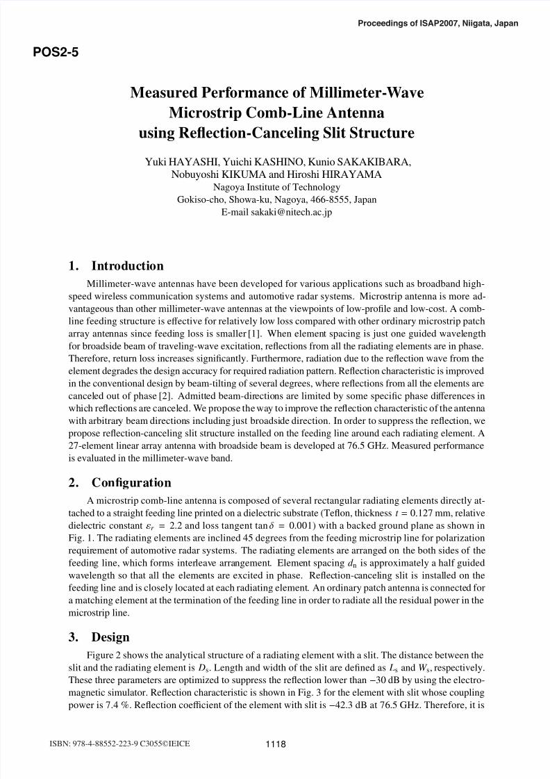
Figure 2 shows the analytical structure of a radiating element with a slit. The distance between the
slit and the radiating element is Ds. Length and width of the slit are defined as Ls and W s, respectively.
These three parameters are optimized to suppress the reflection lower than−
30 dB by using the electro-magnetic simulator. Reflection characteristic is shown in Fig. 3 for the element with slit whose coupling
power is 7.4 %. Reflection coefficient of the element with slit is −42.3 dB at 76.5 GHz. Therefore, it is
Proceedings of ISAP2007, Niigata, Japan
ISBN: 978-4-88552-223-9 C3055©IEICE 1118
POS2-5

8/6/2019 Measured Performance of Millimeter-Wave Micro Strip Comb-Line Antenna
http://slidepdf.com/reader/full/measured-performance-of-millimeter-wave-micro-strip-comb-line-antenna 2/4
confirmed that the reflection from radiating element is canceled sufficiently with the reflection from the
slit.
Microstrip comb-line antenna is designed to operate in traveling wave excitation. The input power
is gradually radiated from all the radiating elements during transmission from the input port toward the
termination. Array design is implemented for Taylor distribution with sidelobe lower than −20 dB. Re-
quired coupling power is designed to be small near the input port and to increase toward the termination.The required variety of coupling is 2.0 ∼ 49.8 %. Radiation from the elements is controlled by variation
of the width W n of the elements where Ln is the resonant length. A 27-element linear array antenna with
broadside beam is designed for experiments.
4. Experiments
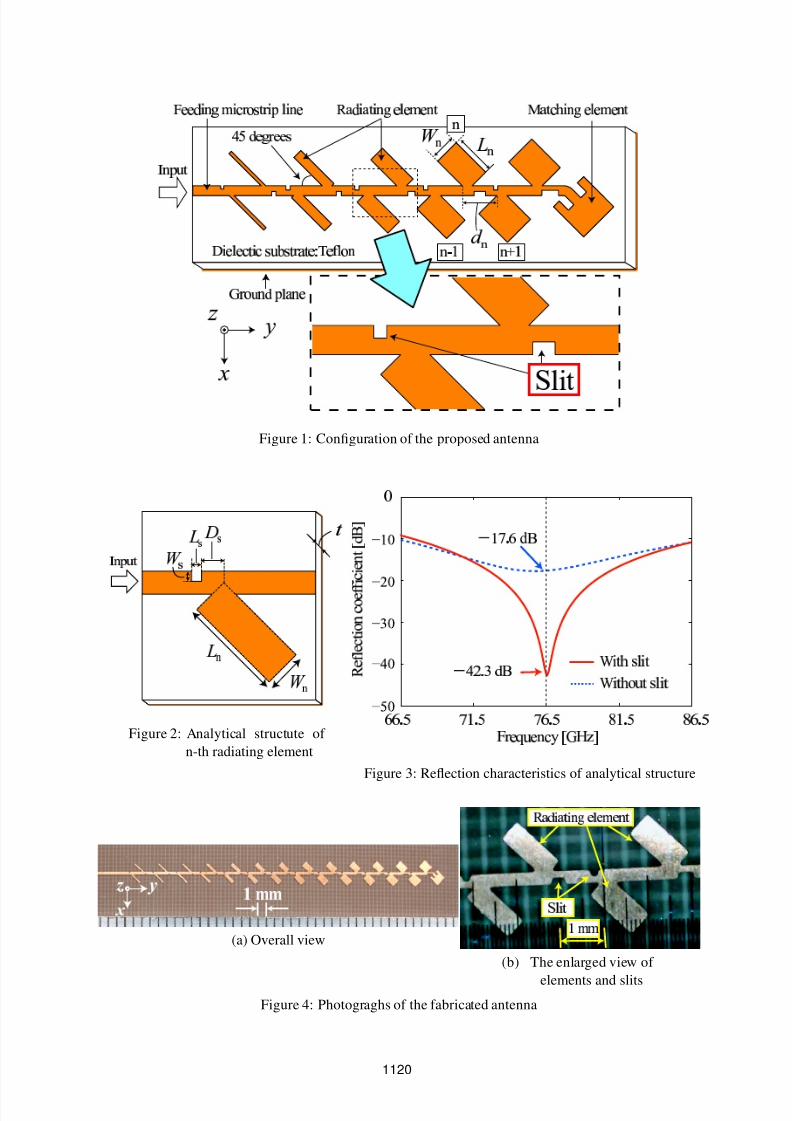
Figures 4 (a) and (b) show photographs of the fabricated antenna. Width of radiating element is
small near the input port and it is large near the termination. Slit is cut on the feeding line at the opposite
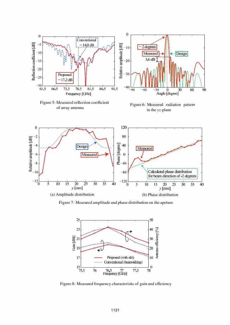
side of each radiating element. Figure 5 shows measured reflection characteristics of fabricated anten-
nas. Reflection-canceling slit is not used in the conventional antenna. Instead, return loss is reduced by
ordinary beam-tilting technique. Reflection coefficient of the proposed antenna is −17.2 dB at the design
frequency 76.5 GHz and is almost the same level with the conventional antenna although the proposedantenna is a broadside array. Thus, the eff ect of reflection-canceling slit is confirmed. Figure 6 shows
measured radiation pattern and array factor of design in yz-plane at 76.5 GHz. The measured radiation
pattern almost agrees well with the array factor. However, some errors are observed in the sidelobe level
and the beam direction. To clarify this cause, the aperture amplitude and phase distribution are shown
in Figs. 7 (a) and (b), respectively. Growing sidelobe is due to error of amplitude distribution. Figure
7 (b) shows the measured phase distribution and the calculated phase distribution for beam direction of
−2 degrees. These phase distributions almost agree with each other. Therefore, error of beam direction
is due to phase distribution. We have already confirmed by using electromagnetic simulator that the fab-
rication error of the etching process aff ects the phase perturbation in transmission through the radiating
element. Figure 8 shows frequency characteristics of gain and antenna efficiency. Since aperture lengths
of proposed and conventional antennas are slightly diff erent depending on the design, directivities arediff erent. The maximum gain is obtained at the design frequency for both antennas. Efficiency of pro-
posed antenna is almost the same level with that of conventional antenna. Consequently, it is confirmed
that the loss due to the slit structure is extremely small.
5. Conclusion
To suppress the reflection from each radiating element, we propose the reflection-canceling slit
structure. A 27-element linear array antenna with broadside beam is designed and fabricated. Reflection
coefficient of proposed antenna is almost the same level with the conventional antenna with beam-tilting
technique although broadside array is designed for the proposed antenna. The measured radiation pattern
almost agrees well with array factor. However, beam direction of measured antenna is −2 degrees. It is
confirmed that the fabrication error of the etching process aff ects the beam direction. We estimate gain
and antenna efficiency. It is confirmed that the loss due to slit structure is extremely small. As a result,
microstrip comb-line antenna with arbitrary beam direction can be designed without increasing return
loss by using reflection-canceling slit structure.
References
[1] H.Iizuka, T.Watanabe, K.Sato and K.Nishikawa, ”Millimeter-wave Microstrip Array Antenna For
Automotive Radar,” IEICE Trans. Commun., Vol.E86-B, No.9 pp.2728-2738, Sept. 2003.
[2] Y.Owa, K.Sakakibara, Y.Tanaka, N.Kikuma and H,Hirayama, ”Low Sidelobe Millimeter-wave
Microstrip Array Antenna Radiation-controlled by Modification of Feeding-line Width,” Proc.ISAP2005, pp.1153-1156, Aug. 2005.
1119
8/6/2019 Measured Performance of Millimeter-Wave Micro Strip Comb-Line Antenna
http://slidepdf.com/reader/full/measured-performance-of-millimeter-wave-micro-strip-comb-line-antenna 3/4
¡ £ ¥ § © ¥ ¥
! # % ( 0 2 3 5 0 9 A ! D E G H E P H R S T V T W T R P
Y
`
a
b
c
d e fh i p
r s t u w x y � � � � � � y t
� � � � � � � � � � � � � � � � � � � k l
n o
{ |
} ~
�
�
Figure 1: Configuration of the proposed antenna
¡
¢
£
¤
¥
¦
§
¨
©
Figure 2: Analytical structute of
n-th radiating element
¡ ¡ £ ¥ § ¨ " # $ % ' (
) 0 2 4 6 7
9 @ B D F G
H I
QR
IS
T
U V
W
S
V
I
Q
Q
U
S
U
I
W
T
X
Y
a
b c d f h d q s u vx w y � �
� � � � � � � � � � �
� � � � �
Figure 3: Reflection characteristics of analytical structure
¡ ¡
¢
£
¤
(a) Overall view
¡ £ ¥
§ ¨ © ¨ ! " ! # !
% & &
(b) The enlarged view of
elements and slits
Figure 4: Photograghs of the fabricated antenna
1120
8/6/2019 Measured Performance of Millimeter-Wave Micro Strip Comb-Line Antenna
http://slidepdf.com/reader/full/measured-performance-of-millimeter-wave-micro-strip-comb-line-antenna 4/4
¡¢ ¤ ¦ ¨ ¨ ! " # $ & ' ( ) 1 2 3 4 6 7
89 A C E A H P Q SU T V W X
Y`
bc
d
e
fgi
d
g
`
b
b
f
d
f
`
i
e
p
qr
s
tu v w v � � �
� � � � � � � � � � � �
� j k
mn
Figure 5: Measured reflection coefficient
of array antenna
¡ ¢ £ ¥ ¦ § ¨
©
!
#
$
#%
&
' ( ) 1 3 5 6 3 ) 9 3 3 C
D E G I P
R S T V X T T Y
a b c d f h b8 i p q r s u w
Figure 6: Measured radiation pattern
in the yz-plane
¡ ¢ £ ¤ ¦ § © ! "
$ %
' (
0
1 2
%
(
45
'
1
0 6
8 %
9
8@
A
B CE D D F
G H I Q S U
W X Y a c e X h
(a) Amplitude distribution
¡ ¢
¤ ¥
§ ¨
! " # % & ( ) 1 2
3 4 5 7 9 A 4 D
F GI H H P
Q
R SU
V
W
X
VY
V
V
a
b c d e g d c i p r t u c v p r y v i � y � g i y � �
�� � � p c � r y � p e i y � � �
� r p � p p v
(b) Phase distribution
Figure 7: Measured amplitude and phase distribution on the apeture
¡
£¤
¦§
©
! # $ & ' ( 0 1 1 3 3 4 6 7 8
9
@A
BC
DE
GH
PQ
ST V X ` V c e f hp i q r s
uv
xy
�
��
x�
��
��
�
��
�
�
���
�
�
�
�
�
��
�
�� j k l n o n o
{ | } { | } | }
Figure 8: Measured frequency characteristic of gain and efficiency
1121