Measured performance of Dolph-chebyshev data-window circuits
4
Measured performance of Dolph-Chebyshev data-window circuits M. Trivedi and K.V. Lever Indexing terms: Digital-analogue conversion, Digital filters, Digital storage, Signal processing Abstract: A circuit comprising a digital memory and a d.a. convertor constitutes a cost-effective method of generating data-window waveforms having optimal frequency-domain equiripple sidelobes. 8-bit quantisation in the memory and harmonic distortion in the d.a. convertor limit the achievable peak/sidelobe ratio to about 51 dB for the near-in sidelobc, and 54 dB for the far-out sidelobes. 1 Introduction We have recently reported 1 the performance of an analogue data-window waveform-generation circuit. In this paper we present an account of a digital circuit which performs the same task. Whereas the repertoire of waveforms that can be implemented in an analogue fashion is somewhat restricted, the digital approach, 2 employing a memory and d.a. convertor, is exceedingly versatile, and it is feasible to attempt the implementation of complicated window wave- forms that are optimal in some sense. There are several optimality criteria that can be applied to this type of signal processing, 3 and we have elected to examine the perform- ance of Dolph-Chebyshev 4 waveforms having equiripple frequency-domain sidelobes which exhibit the least spectral mainlobe broadening for a given sidelobe level. 2 Circuit design The circuit is shown diagrammatically in Fig. 1. A 2 K. e.p.r.o.m., programmed to contain three different window functions is addressed by means of a programmable up/down counter. The starting address of the particular waveform required is determined by means of the initial load switches and the number of waveform samples by means of a simple selector circuit. The e.p.r.o.m. contains only half of the waveform, which is read out during the count-up cycle. The remainder of the waveform is generated during the count- down cycle. To achieve even symmetry about the waveform midpoint, it is necessary to read the midpoint sample twice in succession, and this is easily arranged by inhibiting the appropriate counter clock pulse. Apart from this feature, master .clock sample number select variable bit-width monostable programmable up/down counter if initial load switches e.p.r.o.m AND gates da output trigger pulses for window repetition Fig. 1 Circuit diagram the circuit implementation closely follows that of Reference 2. We have examined three Dolph-Chebyshev waveforms having the following characteristics: (a) 128 samples, — 45 dB sidelobes, Paper T3 10 E, received 2nd October 1978 Mr. Trivedi and Mr. Lever are with the Department of Electronics, Chelsea College, Pulton Place, London SW6 5PR, England ELECTRONIC CIRCUITS AND SYSTEMS, MARCH 1979, Vol. 3, No. 2 peak-broadening 55 dB sidelobes, peak-broadening factor 1 -29 (b) 128 samples, - factor 1 -39 (c) 256 samples, — 55 dB sidelobes, peak-broadening factor 1-39. Each waveform sample is quantised to 8 bits so that all three (half-) waveforms can be accommodated within a 2 K. (2048-bit) single-chip l.s.i. memory. 3 Measured performance The three waveforms are shown in Fig. 2. Note the existence of large impulses at the waveform extremities. These are not erroneous, but are essential to successful implementation in that their absence would deteriorate the designed spectral characteristic. As Harris 3 points out, their presence neatly illustrates the distinction between sampled and continuous windowing techniques; exact implemen- tation of impulses at the extremities (as required by optimal designs) is possible in the discrete format, while only suboptimal approximations can be achieved in the continuous case. 5 The corresponding spectra are shown in Fig. 3. A number of spot frequency measurements are shown in Fig. 4, overplotted on theoretical curves produced by means of a computer model. There are two theoretical curves: the first is the ideal design showing the equiripple behaviour. The second, which can be distinguished by observing the variation of the sidelobe level, is the result of truncating the waveform representation to an 8-bit word length. The measured performance is denoted by crosses, with the estimated experimental errors shown by the length of the crossarms. The agreement between the theoretical and the practical results is generally close for the 45 dB window A (Fig. 4a). The agreement is not as good for the two — 55 dB windows B and C, as shown in Figs. 4b and 4c. An experimental analysis has shown that this departure from the expected performance is not due to 8-bit quanti- sation (which is already taken into account in the second of the theoretical predictions), but to nonlinearity in the d.a. convertor over and above that implied by the quantisation characteristic. That is, the d.a. convertor, which is of the usual resistance ladder type, augments the quantising error by introducing extra harmonic distortion owing to fabrication tolerances on the resistance values. 49 0308-6984/79/020049 + 04 $01-50/0
Transcript of Measured performance of Dolph-chebyshev data-window circuits

Measured performance of Dolph-Chebyshevdata-window circuits
M. Trivedi and K.V. Lever
Indexing terms: Digital-analogue conversion, Digital filters, Digital storage, Signal processing
Abstract: A circuit comprising a digital memory and a d.a. convertor constitutes a cost-effective method ofgenerating data-window waveforms having optimal frequency-domain equiripple sidelobes. 8-bit quantisationin the memory and harmonic distortion in the d.a. convertor limit the achievable peak/sidelobe ratio toabout 51 dB for the near-in sidelobc, and 54 dB for the far-out sidelobes.
1 Introduction
We have recently reported1 the performance of an analoguedata-window waveform-generation circuit. In this paper wepresent an account of a digital circuit which performs thesame task. Whereas the repertoire of waveforms that can beimplemented in an analogue fashion is somewhat restricted,the digital approach,2 employing a memory and d.a.convertor, is exceedingly versatile, and it is feasible toattempt the implementation of complicated window wave-forms that are optimal in some sense. There are severaloptimality criteria that can be applied to this type of signalprocessing,3 and we have elected to examine the perform-ance of Dolph-Chebyshev4 waveforms having equiripplefrequency-domain sidelobes which exhibit the least spectralmainlobe broadening for a given sidelobe level.
2 Circuit design
The circuit is shown diagrammatically in Fig. 1. A 2 K.e.p.r.o.m., programmed to contain three different windowfunctions is addressed by means of a programmable up/downcounter. The starting address of the particular waveformrequired is determined by means of the initial load switchesand the number of waveform samples by means of a simpleselector circuit. The e.p.r.o.m. contains only half of thewaveform, which is read out during the count-up cycle. Theremainder of the waveform is generated during the count-down cycle. To achieve even symmetry about the waveformmidpoint, it is necessary to read the midpoint sample twicein succession, and this is easily arranged by inhibiting theappropriate counter clock pulse. Apart from this feature,
master.clock
samplenumberselect
variable bit-widthmonostable
programmable up/downcounter
ifinitialload
switches
e.p.r.o.mANDgates
daoutput
triggerpulsesfor windowrepetition
Fig. 1 Circuit diagram
the circuit implementation closely follows that ofReference 2.
We have examined three Dolph-Chebyshev waveformshaving the following characteristics:
(a) 128 samples, — 45 dB sidelobes,
Paper T3 10 E, received 2nd October 1978Mr. Trivedi and Mr. Lever are with the Department of Electronics,Chelsea College, Pulton Place, London SW6 5PR, England
ELECTRONIC CIRCUITS AND SYSTEMS, MARCH 1979, Vol. 3, No. 2
peak-broadening
55 dB sidelobes, peak-broadeningfactor 1 -29
(b) 128 samples, -factor 1 -39
(c) 256 samples, — 55 dB sidelobes, peak-broadeningfactor 1-39.Each waveform sample is quantised to 8 bits so that allthree (half-) waveforms can be accommodated within a2 K. (2048-bit) single-chip l.s.i. memory.
3 Measured performance
The three waveforms are shown in Fig. 2. Note theexistence of large impulses at the waveform extremities.These are not erroneous, but are essential to successfulimplementation in that their absence would deteriorate thedesigned spectral characteristic. As Harris3 points out, theirpresence neatly illustrates the distinction between sampledand continuous windowing techniques; exact implemen-tation of impulses at the extremities (as required byoptimal designs) is possible in the discrete format, whileonly suboptimal approximations can be achieved in thecontinuous case.5
The corresponding spectra are shown in Fig. 3. Anumber of spot frequency measurements are shown inFig. 4, overplotted on theoretical curves produced bymeans of a computer model. There are two theoreticalcurves: the first is the ideal design showing the equiripplebehaviour. The second, which can be distinguished byobserving the variation of the sidelobe level, is the result oftruncating the waveform representation to an 8-bit wordlength. The measured performance is denoted by crosses,with the estimated experimental errors shown by the lengthof the crossarms. The agreement between the theoreticaland the practical results is generally close for the 45 dBwindow A (Fig. 4a). The agreement is not as good for thetwo — 55 dB windows B and C, as shown in Figs. 4b and 4c.An experimental analysis has shown that this departurefrom the expected performance is not due to 8-bit quanti-sation (which is already taken into account in the second ofthe theoretical predictions), but to nonlinearity in thed.a. convertor over and above that implied by thequantisation characteristic. That is, the d.a. convertor,which is of the usual resistance ladder type, augmentsthe quantising error by introducing extra harmonicdistortion owing to fabrication tolerances on the resistancevalues.
49
0308-6984/79/020049 + 04 $01-50/0

The performance of the d.a. was tested by measuring theanalogue — analogue linearity of a 12-bit a.d. convertorback to back with the 8-bit d.a. convertor. The assumptionunderlying this measurement, which is likely to be justified,is that compared with the coarser d.a. convertor the a.d.convertor produces negligible distortion, so that all thedistortion of the a.d.—d.a. combination may be attrib-
uted to the latter. The measured distortion of a 100 Hzinput sinewave sampled asynchronously at 10 kHz isshown in Table 1.
For comparison purposes the spectral content of the a.d.input (i.e. the output of the preceding sample and hold unit)is also shown.
As we have shown elsewhere,6 quantisation onlyproduces a distortion of a very-high-order intermodulationindex, of the order of a thousand. These terms are of a
Fig. 2 Dolph-Chebyshev waveforms
(a) Window A: 128 samples, — 45 dB sidelobes: pulse duration =12-8ms
(6) Window B: 128 samples, — 55 dB sidelobes: pulse duration =12-8 ms
(c) Window C: 256 samples, — 55 dB sidelobes: pulse duration =25-6 ms
Horizontal scales: as aboveVertical scales: 2V/division
Fig. 3 Dolph-Chebyshev spectra
(a) Window A(b) Window B(c) Window C
Horizontal scales: 50 Hz/divisionVertical scales: 10 dB/division
50 ELECTRONIC CIRCUITS AND SYSTEMS, MARCH 1979, Vol. 3, No. 2
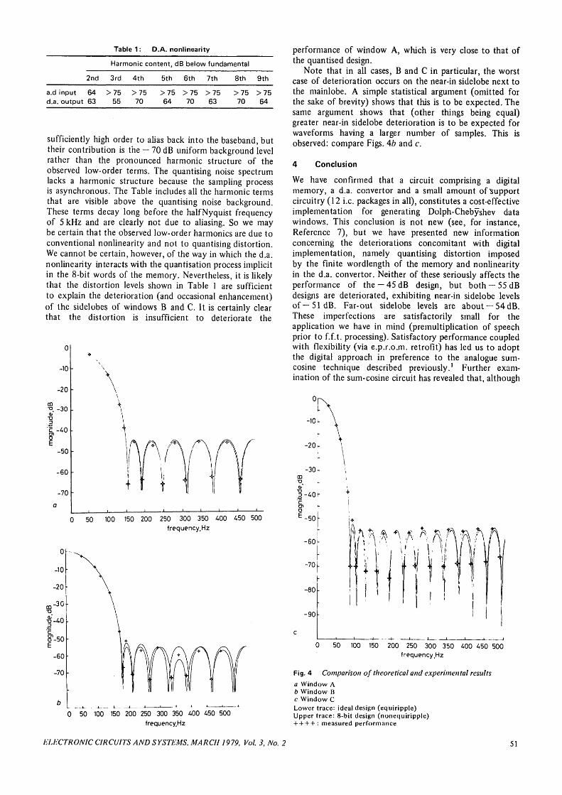
Table 1: D.A. nonlinearity
Harmonic content, dB below fundamental
2nd 3rd 4th 5th 6th 7th 8th 9th
a.d input 64 > 75 > 75d.a. output 63 55 70
>75 >75 >7564 70 63
>75 >7570 64
sufficiently high order to alias back into the baseband, buttheir contribution is the — 70 dB uniform background levelrather than the pronounced harmonic structure of theobserved low-order terms. The quantising noise spectrumlacks a harmonic structure because the sampling processis asynchronous. The Table includes all the harmonic termsthat are visible above the quantising noise background.These terms decay long before the halfNyquist frequencyof 5 kHz and are clearly not due to aliasing. So we maybe certain that the observed low-order harmonics are due toconventional nonlinearity and not to quantising distortion.We cannot be certain, however, of the way in which the d.a.nonlinearity interacts with the quantisation process implicitin the 8-bit words of the memory. Nevertheless, it is likelythat the distortion levels shown in Table 1 are sufficientto explain the deterioration (and occasional enhancement)of the sidelobes of windows B and C. It is certainly clearthat the distortion is insufficient to deteriorate the
0
-10
-20
Qo. -30t>0
-50
-60
-70
0 50 100 150 200 250 300 350 400 450 500frequency.Hz
0
-10
-20
m - 3 0
•§'-40
&-50
-60
-70
performance of window A, which is very close to that ofthe quantised design.
Note that in all cases, B and C in particular, the worstcase of deterioration occurs on the near-in sidelobe next tothe mainlobe. A simple statistical argument (omitted forthe sake of brevity) shows that this is to be expected. Thesame argument shows that (other things being equal)greater near-in sidelobe deterioration is to be expected forwaveforms having a larger number of samples. This isobserved: compare Figs. 4b and c.
4 Conclusion
We have confirmed that a circuit comprising a digitalmemory, a d.a. convertor and a small amount of Supportcircuitry (12 i.e. packages in all), constitutes a cost-effectiveimplementation for generating Dolph-Chebyshev datawindows. This conclusion is not new (see, for instance,Reference 7), but we have presented new informationconcerning the deteriorations concomitant with digitalimplementation, namely quantising distortion imposedby the finite wordlength of the memory and nonlinearityin the d.a. convertor. Neither of these seriously affects theperformance of the — 45 dB design, but both — 55 dBdesigns are deteriorated, exhibiting near-in sidelobe levelsof— 51 dB. Far-out sidelobe levels are about —54dB.These imperfections are satisfactorily small for theapplication we have in mind (premultiplication of speechprior to f.f.t. processing). Satisfactory performance coupledwith flexibility (via e.p.r.cm. retrofit) has led us to adoptthe digital approach in preference to the analogue sum-cosine technique described previously.1 Further exam-ination of the sum-cosine circuit has revealed that, although
0 50 100 150 200 250 300 350 400 450 500frequency.Hz
0 50 100 150 200 250 300 350 400 450 500frequency.Hz
Fig. 4 Comparison of theoretical and experimental resultsa Window Ab Window Bc Window CLower trace: ideal design (equiripple)Upper trace: 8-bit design (nonequiripple)+ + + + : measured performance
ELECTRONIC CIRCUITS AND SYSTEMS, MARCH 1979, Vol. 3, No. 2 51
the performance is satisfactory in all other respects, thereis a need to stabilise the phase of the third harmonicrelative to the fundamental. This could be easily achieved,but the clear advantages of the digital circuit have deterredus from pursuing the analogue approach. Specifically,—55 dBDolph-Chebyshev windows exhibit two practical advantagesover the sum-cosine window:
(a) marginally greater (2-5 dB) peak/sidelobe ratio givingimproved dynamic range
(/?) smaller mainlobe broadening giving frequencyresolution improved by about 20%.
On the other hand, Harris3 has indicated that, in somesituations, the equiripple sidelobe structure of theDolph-Chebyshev windows leads to inaccuracies inmultitone-harmonic analysis due to the coherent additionof sidelobes. Windows designed to have sidelobes thatdecay in magnitude away from the mainlobe have superiorperformance in this respect. In particular, the Kaiser-Bessel8
and Barcilon-Temes9 windows, which are close to optimaland optimal, respectively, according to criteria differentfrom the Dolph-Chebyshev criterion, have this desirabledecaying sidelobe property. We conclude that the circuitdescribed in this paper would be applicable to those casesalso, by substitution of suitably programmed memories.
5 Acknowledgments
We wish to acknowledge the invaluable assistance of A.P.H.McCabe of the GEC Hirst Research Centre, Wembley,Middlesex, for providing software consultancy ande.p.r.o.m. programming facilities.
6 References
1 TRIVEDI, M., and LEVER, K.V: 'Measured performance of asum-cosine data-window circuit', Electron. Lett., 1978, 17, pp.564-566
2 HILL, J.J.: 'A simple digital pulse-shaping circuit', Proc. IEEE,1977,65,p. 1517
3 HARRIS, F.J.: 'On the use of windows for harmonic analysiswith the discrete Fourier transform', ibid., 1978, 66, pp. 51—83,
4 WARD, H.R.: 'Properties of Dolph-Chebyshev weightingfunctions', IEEE Trans., 1973, AES-9, pp. 785-786
5 TAYLOR, T.T.: 'Design of line source antennas of narrowbeamwidth and low side lobes', IRE Trans., 1955, AP-3, pp.16-28
6 LEVER, K.V., and CATTERMOLE, K.W.: 'Quantising noisespectra', Proc. IEE, 1974, 121, (9), pp. 945-954
7 WARDROP, B., and BULL, E.: 'A discrete Fourier transformprocessor using c.c.d.s, Marconi Rev., 1977, XL, p.9
8 KUO, F.F., and KAISER, J.I'.: 'System analysis by digitalcomputer' (Wiley, New York, 1966), pp. 232-238
9 BARCILON, V., and TEMES, G.C.: 'Optimum impulse responseand the van der Maas function', IEEE Trans., 1972, CT-19,pp. 336-342
Mario Biey was born in Torino, Italy,on 21st August 1942. He graduatedwith a degree in electronic engineeringin 1967, from the Politecnico di Torino,Italy. From 1968 to 1969 he servedwith the Italian Army and in 1970 hewas a Research Engineer with theIstituto Elettrotecnico NazionaleGalileo Ferraris, Torino, Italy workingon passive filter design. In 1971 he
joined the Istituto di Elettronica e Telecommicazioni, Polit-ecnico di Torino, Italy, where he is currently in charge ofthe course of electrical network theory. His main interestsare in the areas of passive and active filter design, computer-aided circuit design, and approximation theory.
Amedeo Premoli was born in Crema,a Italy, on 3rd March 1 942. He receivedthe Doctor degree in electronicengineering from the Politecnico diTorino, Torino, Italy, in 1965, and hewas awarded the prize 'SalvatoreChiaudano' for the best degree in hisUniversity. Since 1966 he has beenwith the department of Radiotechno-logy of the Istituto ElettrotecnicoNazionale Galileo Ferraris in Torino.
In 1971 he joined the computer centre, and in 1977 thesystem and circuit group of the same Institute. From 1966to 1972, he was also part-time Assistant Professor inPolitecnico di Torino. His interests are in the field of circuitand system theory, in particular on distributed networks,microstnp analysis, approximation of transfer functions,RC active filters and system reliability.
52 ELECTRONIC CIRCUITS AND SYSTEMS, MARCH 1979, Vol. 3, No. 2
![ULTRA-WIDEBAND ANTENNA ARRAY DESIGN FOR ... Technical...and Dolph-Chebyshev [19]. Depending upon the applications, the antenna engineers have to compromise between the beam width and](https://static.fdocuments.in/doc/165x107/605476a80aa60a4f01786956/ultra-wideband-antenna-array-design-for-technical-and-dolph-chebyshev-19.jpg)


![On the Generalization of Optimal Endfire and Discrete n-bar Array … · 2011. 8. 10. · Zolotarev difference1 pattern [4] is optimum in the Dolph-Chebyshev sense [5], [6]. It has](https://static.fdocuments.in/doc/165x107/610e94e04dac83373853f895/on-the-generalization-of-optimal-endfire-and-discrete-n-bar-array-2011-8-10.jpg)


![UNIVERSITY OF TRENTO - COnnecting REpositories · optimum in the Dolph-Chebyshev sense [2] (i.e., narrowest first null beamwidth and largest normalized difference slope on the boresight](https://static.fdocuments.in/doc/165x107/5e78495e08d7852d3e242381/university-of-trento-connecting-repositories-optimum-in-the-dolph-chebyshev-sense.jpg)