ME8792 POWER PLANT ENGINEERING · ME8792 POWER PLANT ENGINEERING Dr.V.Tamil Selvi , Prof.& Head ,...
92
ME8792 POWER PLANT ENGINEERING Dr.V.Tamil Selvi , Prof.& Head , RMDEEE Ms.Aileen Sonia Dhas , AP/RMDEEE
Transcript of ME8792 POWER PLANT ENGINEERING · ME8792 POWER PLANT ENGINEERING Dr.V.Tamil Selvi , Prof.& Head ,...

ME8792 POWER PLANT ENGINEERING
Dr.V.Tamil Selvi , Prof.& Head , RMDEEE
Ms.Aileen Sonia Dhas , AP/RMDEEE

UNIT IV
POWER FROM RENEWABLE ENERGY

• Hydro Electric Power Plants Classification
Typical Layout and associated components
including Turbines.
• Principle, Construction and working of» Wind
» Tidal
» Solar Photo Voltaic (SPV)
» Solar Thermal
» Geo Thermal
» Biogas
» Fuel Cell power systems.

HYDROELECTRIC
POWER
Hydro electric power
Hydroelectricity is the term referring to
electricity generated by hydropower; the
production of electrical power through the use of
the gravitational force of falling or flowing water

• https://youtu.be/JC-2HIUQBjo
• https://youtu.be/Uhjhufhg3Xk
• https://youtu.be/q8HmRLCgDAI


Classification Of Hydro-Electric Power Plants
1.Classification According To The Availability Of head
–Low head power plant
–Medium head power plant
–High head power plant
2.Classification according to the nature of load
Base load plant
Peak load plant

3. Classification according to the quantity of water available
Run-off river plant without pondageRun-of-the-river power plants may have no water storage at
all or a limited amount of storage, in which case the storage reservoir isreferred to as pondage. A plant without pondage is subject toseasonal riverflows, thus the plant will operate as an intermittent energysource.
Run-off river plant with pondageThis type of plant is used to increase the capacity of
pond.The pond is used as a storage water of hydro electric power plant.Increased the pond size means more water is available in the plant,so such type of hydro electric power plant is used fluctuating load period depending on the size of pondage..
Such type of plant is suitable for both base load or peak load period.During high flow period,this plant is suitable for base load and lean flow period it may be used to supply peak loads only.
During high flood period,one thing should keep in mind that flood should not raise tail-race water level.Such types of power plant save conservation of coal.

Pumped storage plants/Reservoir Powerplants
Most hydroelectric power plant inthe world is reservoir power plant.
In this type of plant, water is storedbehind the dam (and water is availablethroughout the second reservoir constructednear the water outflow from turbine)yeareven in dry season. This type of power plant isvery efficient and it is used both base andpeak load period as per requirement.mostimportantly,it can also take a part of loadcurve in grid system.

Conventional (dams)
• Most hydroelectric power comes from the potential energy
of dammed water driving a water turbine and generator
• The power extracted from the water depends on the volume
and on the difference in height between the source and the
water's outflow .This height difference is called the head.
• The amount of potential energy in water is proportional to
the head
• A large pipe (the "penstock") delivers water to the turbine

12
Run-of-the-river
• Run-of-the-river hydroelectric stations are those with
small or no reservoir capacity, so that the water coming
from upstream must be used for generation at that
moment, or must be allowed to bypass the dam.
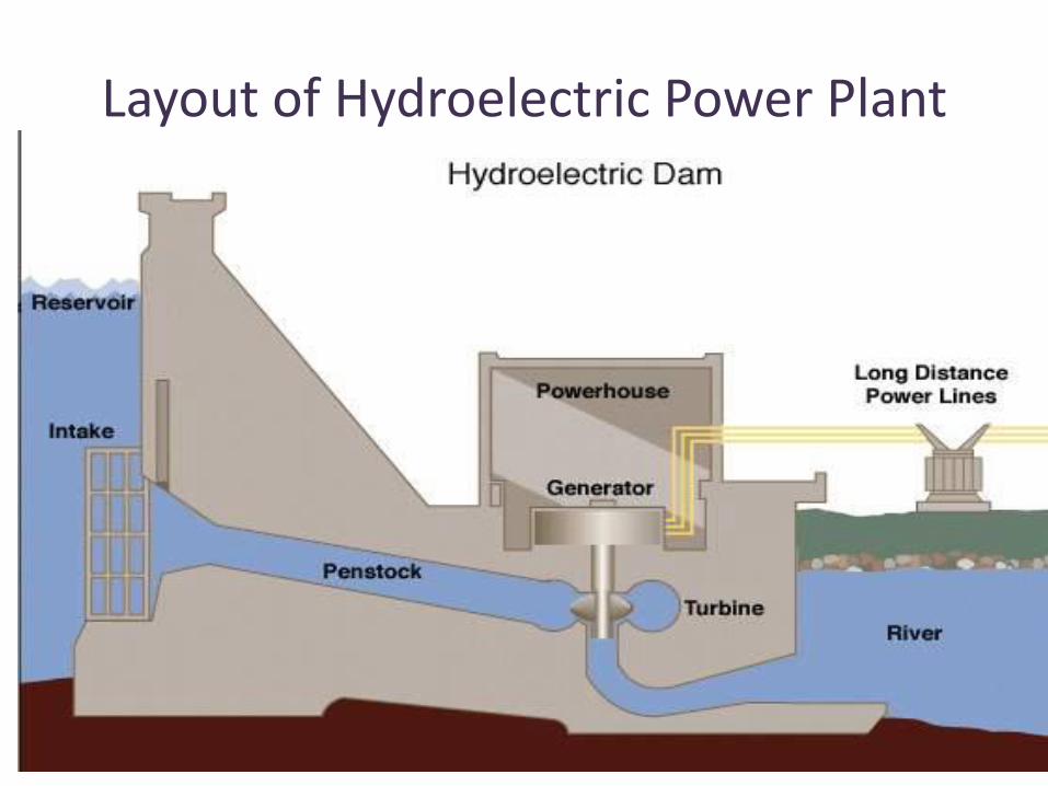
Layout of Hydroelectric Power Plant


Working of
• Dam: controls the flow of water and creates a reservoir of water above for energy use when needed
• Penstock: pipe channeling water from the dam to the turbines
• Turbines: large blades attached to a cylinder that move when the water pushes against it
• Generator: parts connected to the turbines that create the electricity by moving large magnets
• Inductor: changes the form of electricity to one that can be used
• Transmission Lines: transport energy to places that need it

Components of hydro-electric Power Plant
Water Reservoir Dam Spillway- are structures constructed toprovide safe release offlood
waters froma dam toa downstream. Trash rack- water from dam or from canal is provided with trash
rack to prevent the entry of debris which might damage the wicket gates and turbine runners orchoke up the nozzles of the impulse turbine
Forebay- serves as temporary regulating reservoir which is used to store water when the load on the plant is reduced.
Water Tunnel- carries water from the reservoir to surge tank. Canals- a water channel required to the ater to the powerhouse

Penstock Pipeline laid between surge tank and prime mover is known as
penstick
Surge Tank Small reservoir in which the water levelraises or falls to reduce the
pressure c\variation so that the steady flowof water is supplied toallloads.
Water Turbine Water through the penstock ,enters into the turbine through the inlet
valve.
Draft tube Connected at the outlet of the waterturbine
Tail race Water channel or cut and cover conduit.
Powerhouse Turbine,generator,control panels,transformers,auxilliary equipments,etc
are kept.

• Classification based on the power developed by the plant
– Large hydro (>100MW)
– Medium-hydro(15-100MW)
– Smallhydro(1-14 MW)
– Mini-hydro (> 100kW)
– Micro-hydra(5kW upto 100kW)
– Pico-hydro(few hundred watts upto 5kW)

spillway

Surge tank


Low Head Hydroelectrical Generators Low head:Propellor typeTurbines
Power =Change in PotentialEnergy per Unit time
= weight* Vertical drop/time
Energy = Power*time

Moderate Head Hydro
Head: height differenceBetween water level inReservoir and waterLevel entering turbine
Head= height in potentialEnergy equation
Penstock: tube water flowsThrough

High Head Hydro

28
Pico hydroelectricity in Mondulkiri, Cambodia

Francis turbine
Turbine used for moderateHead hydroelectrical powerstatiosn

Water Flow in a Francis Turbine
Left: relative to turbine blades Right: true water path

31
Reaction turbines
• Reaction turbines are acted on by water, which changes pressure as it moves through the turbine and gives up its energy
• They must be encased to contain the water pressure (or suction), or they must be fully submerged in the water flow
• Newton's third law describes the transfer of energy for reaction turbines.
Most water turbines in use are reaction turbines and are used in low (<30m/98 ft) and medium (30-300m/98–984 ft)head applications. In reaction turbine pressure drop occurs in both fixed and moving blades.

32
Impulse turbines
• Impulse turbines change the velocity of a water jet. The jet pushes on the turbine's curved blades which changes the direction of the flow
• The resulting change in momentum (impulse) causes a force on the turbine blades. Since the turbine is spinning, the force acts through a distance (work) and the diverted water flow is left with diminished energy
• Prior to hitting the turbine blades, the water's pressure (potential energy) is converted to kinetic energy by a nozzle and focused on the turbine
• No pressure change occurs at the turbine blades, and the turbine doesn't require a housing for operation
• Newton's second law describes the transfer of energy for impulse turbines• Impulse turbines are most often used in very high (>300m/984 ft) head
applications

Pelton Water Wheel
Used for high head applications:(above 250 meters)Are impulse turbines.
Francis and Propeller type turbineAre reaction turbines.
Reaction turbines: run submerged.
Impulse turbines: run in normal air

34
Types of water turbines
Various types of water turbine runners. From left to right: Pelton Wheel, two types of Francis Turbine and Kaplan Turbine

WIND ENERGY RESOURCES
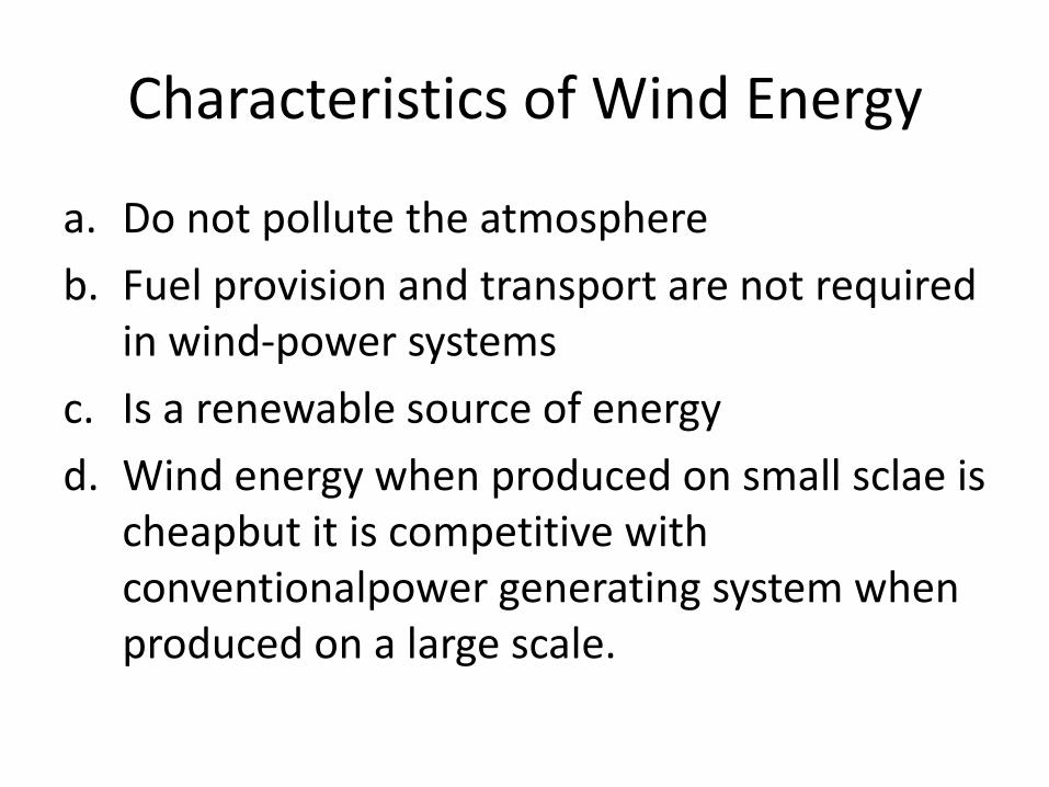
Characteristics of Wind Energy
a. Do not pollute the atmosphere
b. Fuel provision and transport are not required in wind-power systems
c. Is a renewable source of energy
d. Wind energy when produced on small sclae is cheapbut it is competitive with conventionalpower generating system when produced on a large scale.

Principle of Wind Energy Conversion

Types of Wind Energy SystemBased on the force exerted on blades
• Lift type wind turbine– A high speed turbine depends onlift forces tomove the blades
of the wind turbine. The linear speed of the blades is usually several times higher than the wind speed. The torque ofliftforce islow as compared to the drag type
• Drag type wind turbine– Low speed turbines are slower than the wind. They are mainly
driven by the drag force. The torque at the rotor shaft is relatively high.
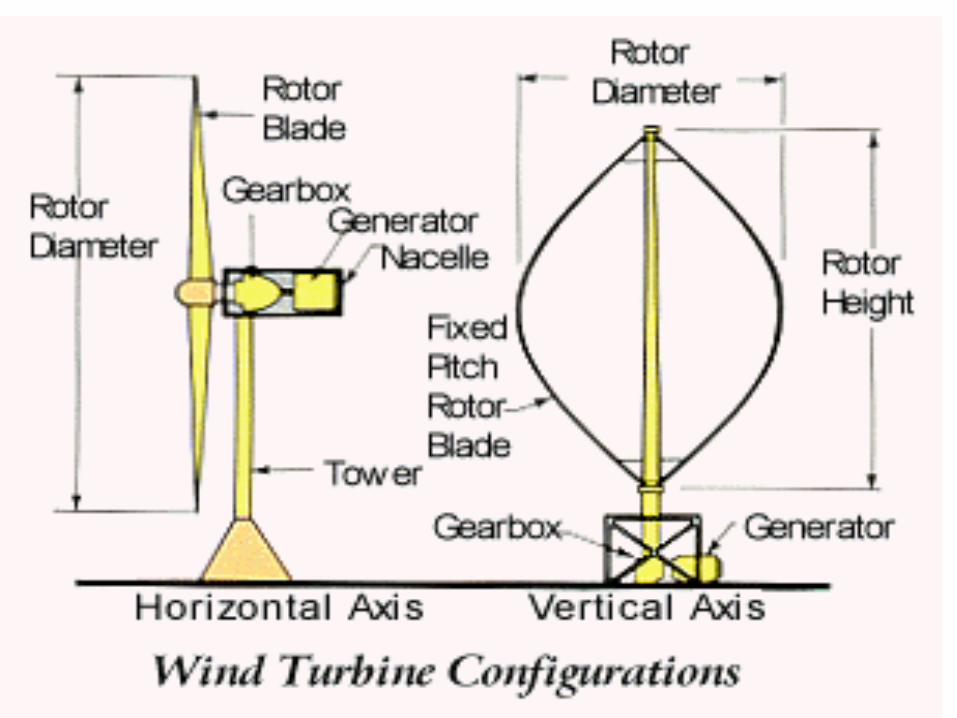
Based on the axis of rotation of the rotor– Horizontal – axis wind machines
– Vertical-axis wind machines


Components of Wind Turbine
• Wind turbine• Nascelle(gearbox,lowand high speed
shafts,generator controller and brake)
• Rotor i.e the assembly of blades
• Hub and shaft
• Transmission system
• Electric generator
• Yaw control system
• Storage
• Energy converters
• Tower to support the rotor system

GENERATING WIND POWER
1
2
3
Attach a voltage probe
Attach a current probe
POWER = VOLTAGE x CURRENT

Types of vertical axis wind turbines
1. Darrieus rotor
2. Savonius rotor
3. Multiple blade rotor
4. Musgrove rotor
5. Evans rotor

https://www.google.co.in/url?sa=i&rct=j&q=&esrc=s&source=imgres&cd=&cad=rja&uact=8&ved=2ahUKEwj2qq65rI_dAhVMo48KHeqiDSkQjRx6BAgBEAU&url=http%3A%2F%2Fwww.mechanicalbooster.com%2F2017%2F01%2Ftypes-of-wind-turbines.html&psig=AOvVaw11zXvVPrcpavI3GoRJPMe_&ust=1535531959661304


TIDAL ENERGY
TIDAL ENERGY
Tidal Energy
– It is a form of hydropower that converts the energy
of tides into useful forms of power ,mainly
electricity.
– It is the only form of energy whose source is the
moon


Types of tidal energy Technologies
• Tidal barrages
• Tidal steam generators
• Dynamic tidal power
» (explanation in video)
Components of Tidal Barrage Power Plants
• Barrage or Dyke or Dam
• Sluice ways
• Embankments
• Power house

COMPONENTS OF TIDAL BARRAGE POWER PLANTS
• Main Components are:– Barrage or Dyke/Dam
– Sluice Ways
– Embankments
– Power House

Modes of operation of Tidal Barrage Power Plants
• Ebb generation
• Flood generation
• Two way genberation
• Pumping and turbinig

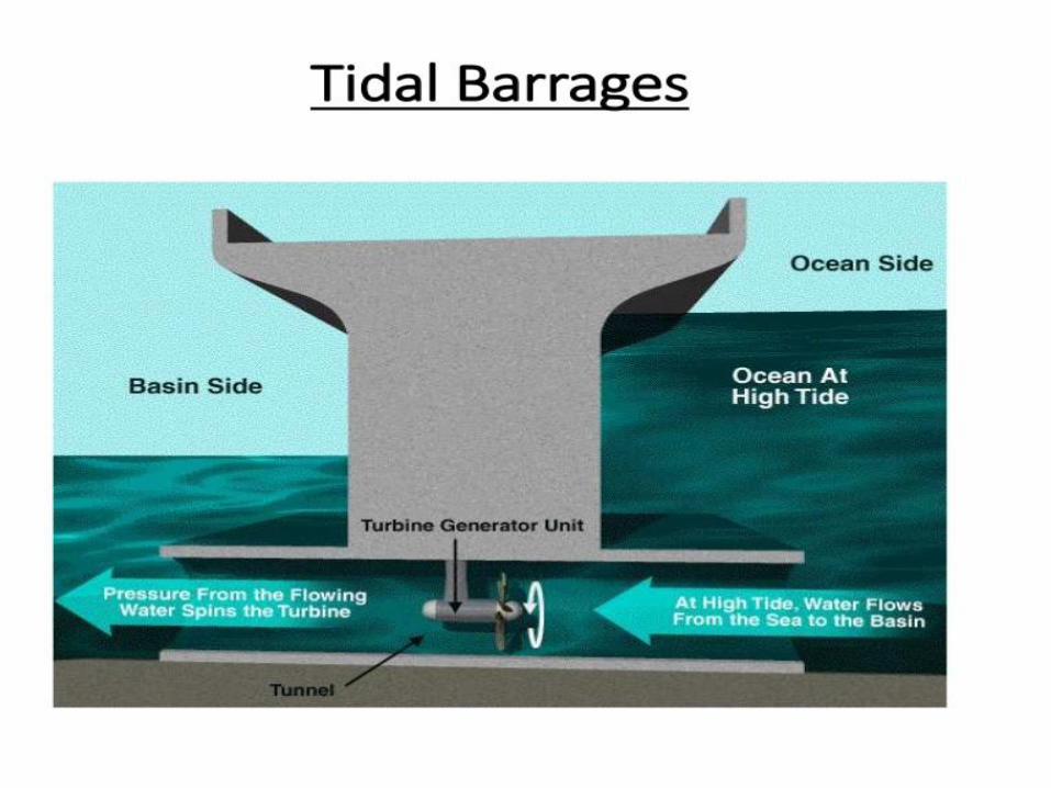
Tidal Barrage
from http://www.esru.strath.ac.uk/EandE/Web_sites/01-
02/RE_info/tidal1.htm

Modes of Operation of Tidal Barrage Power Plants
• Ebb generation
• Flood generation
• Two-way generation

1.Ebb generation

• Flood generation


Modes of generation of tidal barrage power
• Single basin arrangement– Single ebb-cycle system
– Single tide-cycle system
– Double tide –cycle system
• Double basin arrangement


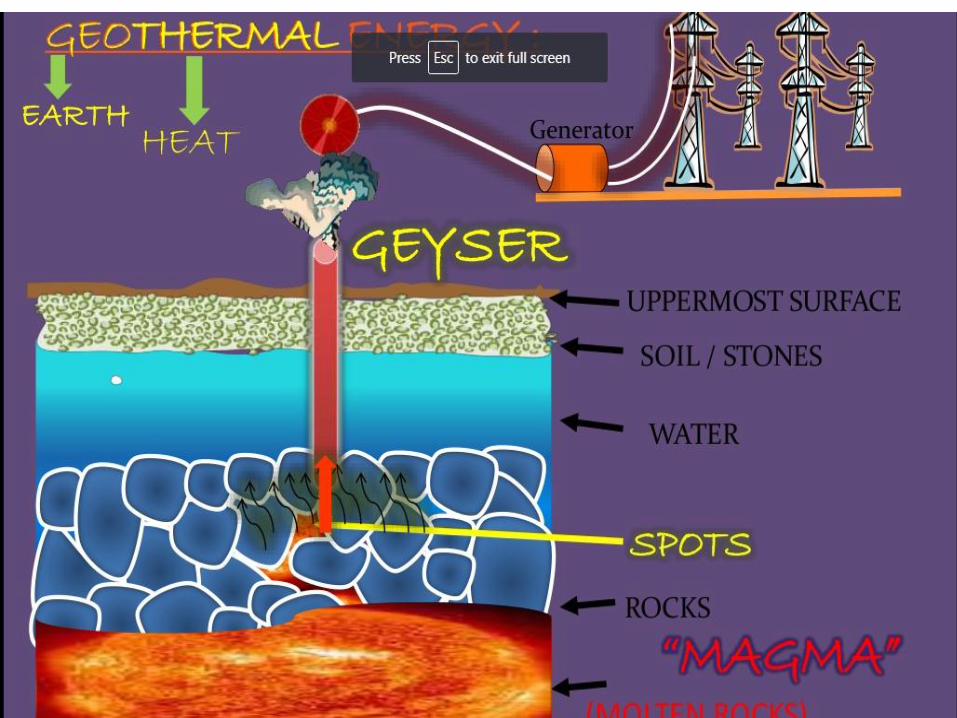
GEO THERMAL ENERGY


GEO THERMAL ENERGY
• Utilize temperature of the earth’s core.
• Direct use: District Heating System
• Electricity generation
• Heat pump


Direct District Heating System
• Use hot water from springs or reservoirs near the surface.
• Hot water near the earth's surface can be piped directly into buildings and industries for heat.

Electricity Generation
• Dry Steam Power Plant: Uses the superheated, pressurized steam (180°-350°C)

Electricity Generation
• Flash Steam Power Plant: use hot water above 182°C (360°F) from geothermal reservoirs.

Electricity Generation
• Binary Cycle Power Plant: – Insufficiently hot resource to efficiently
produce steam
– Too many chemical impurities to allow flashing.

Heat Pumps
• Utilizes constant temperature of upper 10 feet of the Earth’s surface.
• Similar to ordinary heat pumps, but they rely on more stable source than air.


BIO ENERGY
• Energy obtained from organic matter derived from biological organisms (plants and animals) is known as bio energy.
• Biomass energy may be transformed either by chemical/biological process to produce intermediate bio fuels such as methane, producer gas, ethanol & charcoal etc.,


BIOMASS RESOURCES:–Biomass from cultivated fields, crops &
forests
–Biomass from municipal waste, animal dung,
forest waste, agricultuiral waste
USE OF BIO MASS
for producing the process heat, electricity,
gaseous &solid fuels,liquid & chemicals

Factors affecting Digestion Process
1. pH Ocncentration
2. Total Oslid content
3. Seeding
4. Temperatuure
5. Loading rate
6. Type of feed
7. Pressure
8. Nutrients

10.Diameter to depth ratio
11.Mixing of content
12.Retention time/rate of feeding
13.Carbon to nitrogen ratio
14.Uniform feeding


FLOATING DOME TYPE