ME104Q – ENGINEERING OF BRIDGES F2014 – Prof. R. …€¦ · · 2017-10-05ME104Q –...
7
ME104Q – ENGINEERING OF BRIDGES F2014 – Prof. R. Perucchio 1st EXAM - 23 October 2014 – 7:30 –9:30 p.m – Dewey 1-101. EXAMINATION RULES: Please read carefully . The exam is “closed books.” Calculators, triangles, goniometer, and one letter-size page cheat-sheet are allowed . Pages for scratch work will be provided. The exam consists of 3 parts (100 points total) Part 1 (25 points) – two free-body diagram problems, Part 2 (25 points) – one equilibrium problem, Part 3 (50 points) – two truss problems, and One bonus problem. There are 12 numbered pages in the exam. Show all your work on the attached numbered pages only. Write your name on the front page of the exam, and on all the exam pages. Do not start the examination until told to do so! NAME: ______________________________________________
Transcript of ME104Q – ENGINEERING OF BRIDGES F2014 – Prof. R. …€¦ · · 2017-10-05ME104Q –...

ME104Q – ENGINEERING OF BRIDGES F2014 – Prof. R. Perucchio 1st EXAM - 23 October 2014 – 7:30 –9:30 p.m – Dewey 1-101.
EXAMINATION RULES: Please read carefully. The exam is “closed books.” Calculators, triangles, goniometer, and one letter-size page cheat-sheet are allowed. Pages for scratch work will be provided. The exam consists of 3 parts (100 points total) Part 1 (25 points) – two free-body diagram problems, Part 2 (25 points) – one equilibrium problem, Part 3 (50 points) – two truss problems, and One bonus problem. There are 12 numbered pages in the exam. Show all your work on the attached numbered pages only. Write your name on the front page of the exam, and on all the exam pages. Do not start the examination until told to do so! NAME: ______________________________________________
!
A B C
D
P
E F
1.1 Draw the free-body diagram (F-BD) of THE ENTIRE BRIDGE. Draw first a coordinate system and then be accurate in drawing the F-BD.
PART 1 (25 points): Draw the free-body diagram (F-BD) for each of the three systems shown below. Draw first a coordinate system and then be accurate in drawing the F-BD. The structure of the Quebec Bridge consisting of two cantilever sections and a simply supported central section is shown schematically below. The sections are connected with hinges at A, B, C, and D. The bridge piers are fully constrained at E and F. We consider only the live load P acting as shown and ignore the dead loads.
ME104QFall2014 ex1 2 Name__________________
1.2 Draw the free-body diagram (F-BD) of THE LEFT CANTILEVER SECTION AB. Draw first a coordinate system and then be accurate in drawing the F-BD.
1.3 Assume now that the central section is fully constrained at B and C. Draw the free-body diagram (F-BD) of THE RIGHT CANTILEVER SECTION CD. Draw first a coordinate system and then be accurate in drawing the F-BD.
ME104QFall2014 ex1 3 Name__________________
A B
P
E
Q
h
s s
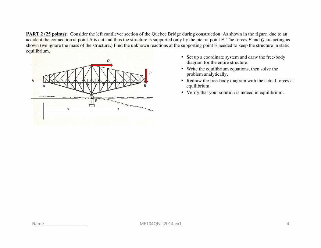
PART 2 (25 points): Consider the left cantilever section of the Quebec Bridge during construction. As shown in the figure, due to an accident the connection at point A is cut and thus the structure is supported only by the pier at point E. The forces P and Q are acting as shown (we ignore the mass of the structure.) Find the unknown reactions at the supporting point E needed to keep the structure in static equilibrium.
• Set up a coordinate system and draw the free-body diagram for the entire structure.
• Write the equilibrium equations, then solve the problem analytically.
• Redraw the free-body diagram with the actual forces at equilibrium.
• Verify that your solution is indeed in equilibrium.
ME104QFall2014 ex1 4 Name__________________
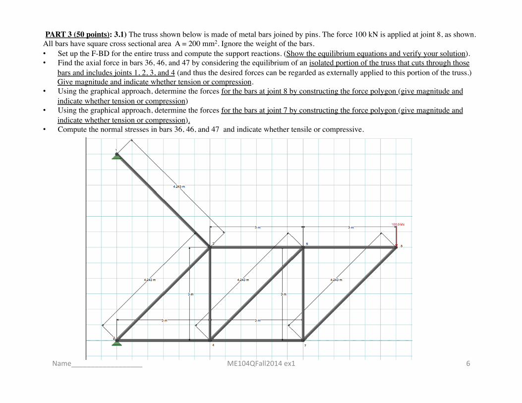
PART 3 (50 points): 3.1) The truss shown below is made of metal bars joined by pins. The force 100 kN is applied at joint 8, as shown. All bars have square cross sectional area A = 200 mm2. Ignore the weight of the bars. • Set up the F-BD for the entire truss and compute the support reactions. (Show the equilibrium equations and verify your solution). • Find the axial force in bars 36, 46, and 47 by considering the equilibrium of an isolated portion of the truss that cuts through those
bars and includes joints 1, 2, 3, and 4 (and thus the desired forces can be regarded as externally applied to this portion of the truss.) Give magnitude and indicate whether tension or compression.
• Using the graphical approach, determine the forces for the bars at joint 8 by constructing the force polygon (give magnitude and indicate whether tension or compression)
• Using the graphical approach, determine the forces for the bars at joint 7 by constructing the force polygon (give magnitude and indicate whether tension or compression).
• Compute the normal stresses in bars 36, 46, and 47 and indicate whether tensile or compressive.
ME104QFall2014 ex1 6 Name__________________
ME104QFall2014 ex1 9
file://localhost/Users/rlp/Documents/Documents%20Work/Courses/ME104Q%20Fall2014/EXAMS/ME104QF2014%20Exam1/ex1%20Truss/ME104QF14%20ex1%20part3%20truss%20p2Print Date: October 23, 2014 at 11:10AM
Home View
Load Combination: Scratch: 1.00S
Support Reactions
NodeID R_x (kN) R_y (kN) M_z (kN-m)
1 -400.0000 0.0000 0.0000
2 400.0000 200.0000 0.0000
NodeID R_x (kN) R_y (kN) M_z (kN-m)
Joint Displacements
ID U_x (mm) U_y (mm) Theta_z (rad)
1 0.000000e+00 0.000000e+00 0.000000e+00
2 0.000000e+00 0.000000e+00 0.000000e+00
3 3.100814e-01 -7.486027e-01 0.000000e+00
4 -1.550407e-01 -9.036434e-01 0.000000e+00
6 4.651221e-01 -1.962327e+00 0.000000e+00
ID U_x (mm) U_y (mm) Theta_z (rad)
Member Results
ID F_axial(kN) V_i(kN) V_j(kN) M_i(kN-m) M_j(kN-m) V_max(kN) loc(m) V_min(kN) loc(m) M_max(kN-m) loc(m) M_min(kN-m) loc(m)
2-3 -282.8427 0.0000 0.0000 -0.0000 0.0000 0.0000 0.0000 0.0000 0.0000 -0.0000 0.0000 -0.0000 0.0000
1-3 400.0000 0.0000 0.0000 0.0000 0.0000 0.0000 0.0000 0.0000 0.0000 0.0000 0.0000 0.0000 0.0000
4-3 200.0000 0.0000 0.0000 -0.0000 0.0000 0.0000 0.0000 0.0000 0.0000 0.0000 0.0000 0.0000 0.0000
2-4 -200.0000 0.0000 0.0000 0.0000 -0.0000 0.0000 0.0000 0.0000 0.0000 0.0000 0.0000 0.0000 0.0000
4-6 -282.8427 0.0000 0.0000 -0.0000 0.0000 0.0000 0.0000 0.0000 0.0000 -0.0000 0.0000 -0.0000 0.0000
3-6 200.0000 -0.0000 -0.0000 0.0000 -0.0000 -0.0000 0.0000 -0.0000 0.0000 0.0000 0.0000 0.0000 0.0000
ID F_axial(kN) V_i(kN) V_j(kN) M_i(kN-m) M_j(kN-m) V_max(kN) loc(m) V_min(kN) loc(m) M_max(kN-m) loc(m) M_min(kN-m) loc(m)
file://localhost/Users/rlp/Documents/Documents%20Work/Courses/ME104Q%20Fall2014/EXAMS/ME104QF2014%20Exam1/ex1%20Truss/ME104QF14%20ex1%20part3%20truss%20p2Print Date: October 23, 2014 at 11:17AM
Home View
Load Combination: Scratch: 1.00S
Support Reactions
NodeID R_x (kN) R_y (kN) M_z (kN-m)
1 0.0000 0.0000 0.0000
2 0.0000 0.0000 0.0000
NodeID R_x (kN) R_y (kN) M_z (kN-m)
Joint Displacements
ID U_x (mm) U_y (mm) Theta_z (rad)
1 0.000000e+00 0.000000e+00 0.000000e+00
2 0.000000e+00 0.000000e+00 0.000000e+00
3 0.000000e+00 0.000000e+00 0.000000e+00
4 0.000000e+00 0.000000e+00 0.000000e+00
6 0.000000e+00 0.000000e+00 0.000000e+00
ID U_x (mm) U_y (mm) Theta_z (rad)
Member Results
ID F_axial(kN) V_i(kN) V_j(kN) M_i(kN-m) M_j(kN-m) V_max(kN) loc(m) V_min(kN) loc(m) M_max(kN-m) loc(m) M_min(kN-m) loc(m)
2-3 0.0000 0.0000 0.0000 0.0000 0.0000 0.0000 0.0000 0.0000 0.0000 0.0000 0.0000 0.0000 0.0000
1-3 0.0000 0.0000 0.0000 0.0000 0.0000 0.0000 0.0000 0.0000 0.0000 0.0000 0.0000 0.0000 0.0000
4-3 0.0000 0.0000 0.0000 0.0000 0.0000 0.0000 0.0000 0.0000 0.0000 0.0000 0.0000 0.0000 0.0000
2-4 0.0000 0.0000 0.0000 0.0000 0.0000 0.0000 0.0000 0.0000 0.0000 0.0000 0.0000 0.0000 0.0000
4-6 0.0000 0.0000 0.0000 0.0000 0.0000 0.0000 0.0000 0.0000 0.0000 0.0000 0.0000 0.0000 0.0000
3-6 0.0000 0.0000 0.0000 0.0000 0.0000 0.0000 0.0000 0.0000 0.0000 0.0000 0.0000 0.0000 0.0000
ID F_axial(kN) V_i(kN) V_j(kN) M_i(kN-m) M_j(kN-m) V_max(kN) loc(m) V_min(kN) loc(m) M_max(kN-m) loc(m) M_min(kN-m) loc(m)
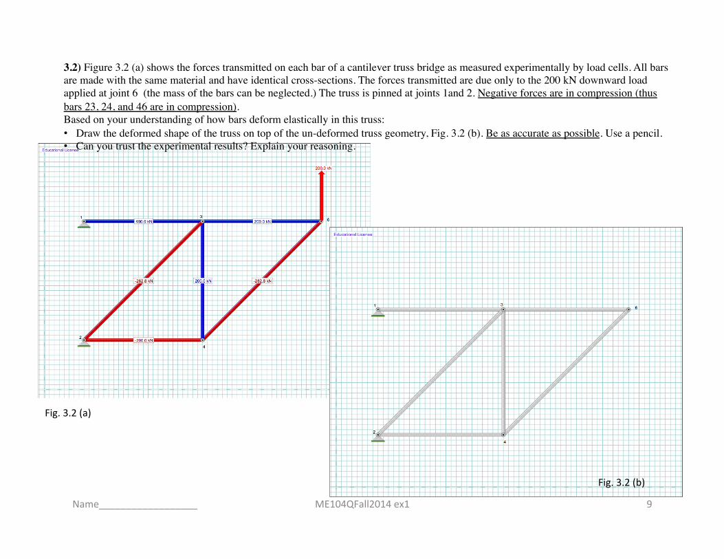
3.2) Figure 3.2 (a) shows the forces transmitted on each bar of a cantilever truss bridge as measured experimentally by load cells. All bars are made with the same material and have identical cross-sections. The forces transmitted are due only to the 200 kN downward load applied at joint 6 (the mass of the bars can be neglected.) The truss is pinned at joints 1and 2. Negative forces are in compression (thus bars 23, 24, and 46 are in compression). Based on your understanding of how bars deform elastically in this truss: • Draw the deformed shape of the truss on top of the un-deformed truss geometry, Fig. 3.2 (b). Be as accurate as possible. Use a pencil. • Can you trust the experimental results? Explain your reasoning.
Fig. 3.2 (a)
Fig. 3.2 (b)
Name__________________
A B
W
E
h
s s
F
R
ME104QFall2014 ex1 11
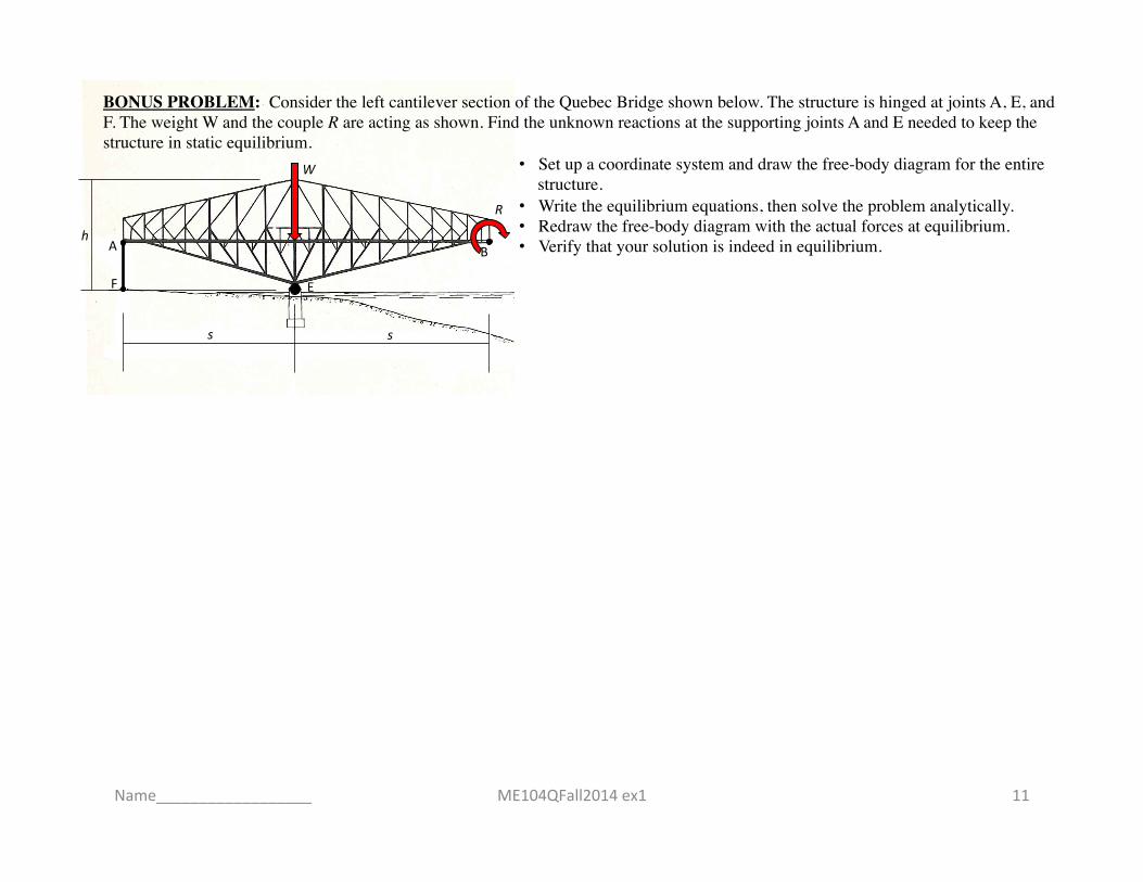
BONUS PROBLEM: Consider the left cantilever section of the Quebec Bridge shown below. The structure is hinged at joints A, E, and F. The weight W and the couple R are acting as shown. Find the unknown reactions at the supporting joints A and E needed to keep the structure in static equilibrium.
• Set up a coordinate system and draw the free-body diagram for the entire structure.
• Write the equilibrium equations, then solve the problem analytically. • Redraw the free-body diagram with the actual forces at equilibrium. • Verify that your solution is indeed in equilibrium.
Name__________________