ME Online Exclusive Gearless drives...
4
www.miningengineeringmagazine.com Mınıng engıneerıng JUNE 2014 1 Gearless drives for high-capacity belt conveyors by Takraf B elt conveyors in hardrock mining determine the development of belt conveyor components on the high end of their performance spectrum. New requirements with regard to conveyor geometries and mass flows make it necessary to think about alternative drive concepts. When it comes to drive sizes exceeding 3,500 kW per individual drive, there are no conventional electromechanical drives with electric motors and helical bevel gears. Gearless drives, like those that are state of the art for the mine hoists implemented in underground mining operations, allow the use of larger drive units and are increasingly being used to drive belt conveyors. Individual belt conveyors in hard ock mining operations all over the world can now extend to distances of up to 16.8 km (10 miles) and overcome height differences of up to 500 m (1,640 ft), while normally achieving outputs of approximately 10.8 kt/h (12,000 stph). Such belt conveyors have had a significant impact on the development of individual components. Conveyor belts with strength of up to 7,800 N/mm are still in use today. Electromechanical drives, consisting of electrical motors (wound rotor or squirrel cage motor) and helical bevel gears with a capacity of up to 3,150 kW, are currently in use in South American copper mines. The performance limits of belt conveyors are redefined by lower ore contents and deeper deposits. Conveyors are now routed through the tunnel systems such that the maximum length available is required in order to reduce the number of underground transfer stations. This leads to new requirements on the quality of the conveyor belts. The St 10,000 with strength of 10,000 N/mm of belt width is now available. An alternative for continuously improving belt quality with ever-increasing drives located at both ends of the conveyor is to optimize the application of drive forces on the belt. Possible alternatives include: • Belt on belt drives (TT drives). • Intermediate drives in the top strand and/ or bottom strand. • Driven carrying rollers (Alles, Rainer). Unfortunately, it is not always possible to implement such drive concepts. For driven carrying rollers, there is still not a cost-effective and reliable solution. That is why the current development projects focus on adapting conveyors with the traditional head and/or tail pulley drive systems to new challenges and demands. Takraf GmbH is currently involved in studies that focus on a belt conveyor system that uses belts having a strength class of St 10,000. The limits of conventional drives with helical bevel gears are exceeded with the required drive capacity of 21,000 kW per individual conveyor. Low- speed synchronous motors, like those frequently implemented as drive solution for mine hoists in underground mining operations, do permit larger drive capacities. As part of the above-mentioned study, a conveyor is equipped with three gearless drives, each delivering an output of 7,000 kW. Gearless drive systems for belt conveyors – maintenance and efficiency The advantages of gearless drives compared to electromechanical drives cannot only be reduced to the possibility of installing larger drive units. The curve of the motor’s efficiency in relation to the motor’s torque shows over the entire spectrum values that are above the characteristics of traditional conveyor drives with wound rotor or squirrel cage motors completed with gears (Fig. 1). Belt conveyors do not always work at full load over the entire period of operation. Partial load ME Online Exclusive Motor efficiency as a function of the motor’s utilization ratio. Source: ABB. Figure 1
Transcript of ME Online Exclusive Gearless drives...

www.miningengineeringmagazine.com Mınıng engıneerıng JUNE 2014 1
Gearless drives for high-capacity belt conveyorsby Takraf
Belt conveyors in hardrock mining determine the development of belt
conveyor components on the high end of their performance spectrum. New requirements with regard to conveyor geometries and mass flows make it necessary to think about alternative drive concepts. When it comes to drive sizes exceeding 3,500 kW per individual drive, there are no conventional electromechanical drives with electric motors and helical bevel gears. Gearless drives, like those that are state of the art for the mine hoists implemented in underground mining operations, allow the use of larger drive units and are increasingly being used to drive belt conveyors.
Individual belt conveyors in hard ock mining operations all over the world can now extend to distances of up to 16.8 km (10 miles) and overcome height differences of up to 500 m (1,640 ft), while normally achieving outputs of approximately 10.8 kt/h (12,000 stph).
Such belt conveyors have had a significant impact on the development of individual components. Conveyor belts with strength of up to 7,800 N/mm are still in use today. Electromechanical drives, consisting of electrical motors (wound rotor or squirrel cage motor) and helical bevel gears with a capacity of up to 3,150 kW, are currently in use in South American copper mines.
The performance limits of belt conveyors are redefined by lower ore contents and deeper deposits. Conveyors are now routed through the tunnel systems such that the maximum length available is required in order to reduce the number of underground transfer stations. This leads to new requirements on the quality of the conveyor belts. The St 10,000 with strength of 10,000 N/mm of belt width is now available.
An alternative for continuously improving belt quality with ever-increasing drives located at both ends of the conveyor is to optimize the application of drive forces on the belt. Possible alternatives include:
• Belt on belt drives (TT drives).• Intermediate drives in the top strand and/
or bottom strand.• Driven carrying rollers (Alles, Rainer).Unfortunately, it is not always possible to
implement such drive concepts. For driven carrying rollers, there is still not a cost-effective and reliable solution. That is why the current development projects focus on adapting conveyors with the traditional head and/or tail pulley drive systems to new challenges and demands.
Takraf GmbH is currently involved in studies that focus on a belt conveyor system that uses belts having a strength class of St 10,000. The limits of conventional drives with helical bevel gears are exceeded with the required drive capacity of 21,000 kW per individual conveyor. Low-speed synchronous motors, like those frequently implemented as drive solution for mine hoists in underground mining operations, do permit larger drive capacities. As part of the above-mentioned study, a conveyor is equipped with three gearless drives, each delivering an output of 7,000 kW.
Gearless drive systems for belt conveyors – maintenance and efficiency
The advantages of gearless drives compared to electromechanical drives cannot only be reduced to the possibility of installing larger drive units. The curve of the motor’s efficiency in relation to the motor’s torque shows over the entire spectrum values that are above the characteristics of traditional conveyor drives with wound rotor or squirrel cage motors completed with gears (Fig. 1).
Belt conveyors do not always work at full load over the entire period of operation. Partial load
ME Online Exclusive
Motor efficiency as a function of the motor’s utilization ratio. Source: ABB.
Figure 1
2 JUNE 2014 Mınıng engıneerıng www.miningengineeringmagazine.com
conditions and even (short-term) idle periods are all part of a belt conveyor’s operating regime. While asynchronous motors perform at lower efficiency levels with lower utilization ratios, the efficiency of synchronous motors increases in this range.
The higher efficiency of synchronous motors in general and especially in the partial load range and the fact that mechanical loads are eliminated during transfer of torque lead to lower operating costs for the conveyor.
The maintenance of the gear unit including oil change intervals can be omitted just like the maintenance of the high-speed coupling. This is of particular interest wherever maintenance processes involve considerable effort. Prime examples of this would be operating conveyors in Canada at ambient temperatures of -45°C
(-49°F) or conveyor systems that set up at an altitude of 4,500 m (14,700 ft) and more above sea level.
Structure of gearless conveyor drivesA synchronous motor consists of a rotor that is
connected with the drive pulley shaft and a stator that rests on a foundation or a corresponding steel structure (Fig. 2).
Compared to conventional belt conveyor drives, the drive unit with gear box and asynchronous motor is replaced with a synchronous motor.
The following conditions must be taken into consideration if gearless drives are used:
• Deflection of the drive pulley shaft at the shaft end due to the various belt tensions at the different load and operating conditions.
• Possible settling of foundations of the stator or deformation of structural steel used to support the stator.
• Possibility for readjusting the entire drive in case of belt misalignment during commissioning.
A prerequisite is the need to comply with the permissible deviations in the motor’s air gap. Since the design of the motor, motor mount, drive pulley and the associated structural steel are closely tied together, Takraf GmbH has formed a cooperation agreement with ABB. This approach makes it possible to select a joint motor concept during component planning considering client specifications and site conditions.
The following systems are worth considering as a motor concept:
1. Bearingless motor: The rotor is directly connected to the drive pulley shaft (by means of a flange connection). The stator is supported separately.
2. Bearing motor: The motor has two bearings. The stator is secured to the foundation or steel structure. A flexible coupling is used to facilitate the transfer of torque between the rotor and the drive pulley.
3. Diaphragm coupling: Compared to the bearing motor, the motor mount on the output shaft side and the flexible coupling is replaced by a diaphragm coupling.
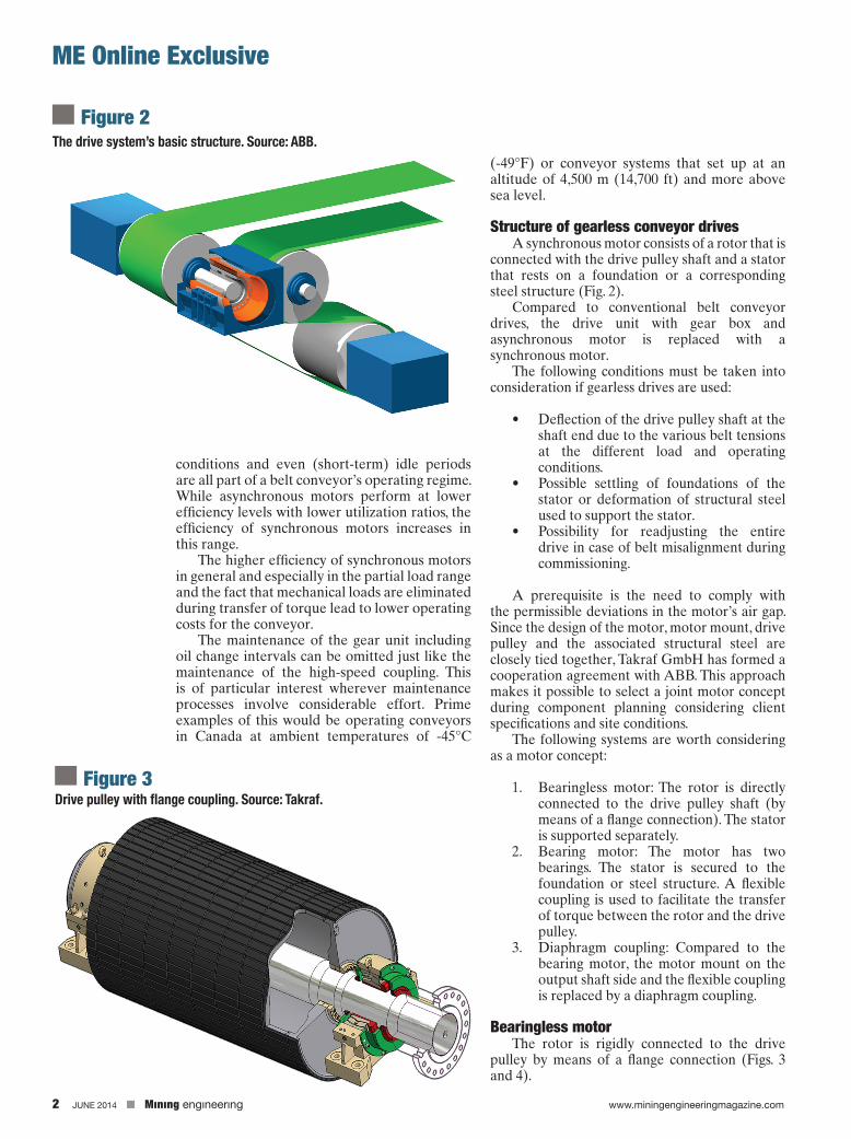
Bearingless motorThe rotor is rigidly connected to the drive
pulley by means of a flange connection (Figs. 3 and 4).
ME Online Exclusive
The drive system’s basic structure. Source: ABB.
Figure 2
Drive pulley with flange coupling. Source: Takraf.Figure 3

www.miningengineeringmagazine.com Mınıng engıneerıng JUNE 2014 3
ME Online Exclusive
Compared to the standard layout, an additional criterion is necessary for dimensioning the drive pulley. The deflection of the pulley shaft at the coupling flange may not exceed the narrow tolerances that result from the permissible deviations in the air gap between the rotor and stator. That leads to drive pulley structures with large shaft diameters (Figs. 5 and 6).
Since the rigidness of the stator mount determines the tolerances in the motor’s air gap to the same extent, it is necessary to offer solutions with very limited deformations that also allow a subsequent alignment of the stator during commissioning of the conveyor. Drive realignment would be necessary if a proper belt alignment could to be reached by drive pulley readjustment only.
Bearing motorFor the solution previously described, motor
bearings are not needed. No special coupling is required for connecting the motor to the drive pulley. A rigid flange connection is sufficient.
Unfortunately, bearingless motors also have disadvantages, such as:
• Special drive pulley design to decrease shaft deflection.
• The motor must be assembled on site, since the rotor first has to be connected with the pulley shaft and the stator is then moved over the rotor. This means that the motor must be disassembled again after factory assembly and completion of test run.
• In case of damage, the motor cannot be disconnected quickly and/or replaced with a spare drive.
• For the load case earthquakes, it is necessary to take into consideration the large (rotor) masses at the cantilevered drive shaft end.
The disadvantages described here with regard to bearingless motors have led to working with ABB to design a motor with separate bearings as an alternative.
Diaphragm couplingWith regard to the bearing motor previously
described, the motor and drive pulley are connected by means of a flexible coupling (Fig. 7). A gear coupling was selected as suitable transfer element for the torque being transferred and the permissible angular deviation of both shafts.
For very large motors (6,000 kW to 8,000 kW of driving power), geared couplings reach their limits. The drive concept with bearingless motors
has resulted in heavy and expensive drive pulleys due to the deflection of the pulley shaft in the area of very large drives.
Based on the disadvantages of a bearingless motor, a motor concept with a bearing at motor N-end and a diaphragm coupling to connect the rotor with the drive pulley was developed. The diaphragm coupling combines the functions of the bearing at the motor D-End and the geared coupling between rotor and pulley (Fig. 8).
To transport the motor, a support structure will be placed on the motor frame, which secures the rotor shaft on the side with the output shaft end.
Deformation at the drive pulley. Source: Takraf.
Figure 4
Stator during installation. Source: ABB.Figure 5

4 JUNE 2014 Mınıng engıneerıng www.miningengineeringmagazine.com
This also provides the option to quickly separate the motor and the drive pulley by opening the coupling in case of an emergency.
ProjectsIn 2012, Takraf was awarded a contract by
the Chilean mine operator Codelco to deliver conveyors with 12 gearless belt drives for the world’s largest underground copper mine, El Teniente. During the final construction phase of these conveyors, approximately 10.8 kt/h (12,000 stph) of copper ore will be transported over a total distance of 11.5 km (7.1 miles). The drive motors each have an output of 2,500 kW. As a result of extensive discussions with the customer, the principle of the bearing motor was implemented for this contract.
The commissioning of the first motor is slated for 2014.
SummaryGearless drives are expanding the service
range of drives of belt conveyors. Individual drives with a driving power of up to 8,000 kW are possible. Studies on the use of gearless drives of this performance class are currently being carried out in the current projects.
When it comes to maintenance and energy efficiency, gearless drives offer advantages compared to the conventional electromechanical solutions.
The drive motor can be designed as bearingless, with bearings or with diaphragm coupling. Motor size, site conditions and customer requirements form the basis for the solution that is to be implemented. n
ReferencesAlles, Rainer: Zum Zwischenantrieb von Gurtförderern mittels
angetriebener Tragrollen und Linearmotoren; Dissertation TU Hannover, 1976
ME Online Exclusive
Rotor during installation. Source: ABB.
Figure 6
Bearing motor with flexible coupling, brake disc, drive pulley and the atent-pending support structure. Source: Takraf.
Figure 7
Bearing motor with diaphragm coupling (patent pending), brake disc, drive pulley and the support structure. Source: Takraf.
Figure 8