ME 6505 DYNAMICS OF MACHINES Fifth Semester … Semester Mechanical Engineering (Regulations 2013)...
18
ME 6505 – DYNAMICS OF MACHINES Fifth Semester Mechanical Engineering (Regulations 2013) Unit – II PART – A 1. Define static balancing of shaft. (N/D – 15) The net dynamic force acting on the shaft is equal to zero. This requires that the line of action of three centrifugal forces must be the same. In other words, the centre of the masses of the system must lie on the axis of rotation. This is the condition for static balancing. 2. State the reasons for choosing multi-cylinder engine in compression with that of the single cylinder engine. (N/D – 15) The reason for choosing multi-cylinder engine in comparison with that of a single cylinder engine is that, the balancing will be easier. The unbalanced force created by one cylinder or reciprocation is compensated by other. 3. Differentiate: Static and Dynamic balancing. (M/J – 16) S.No. Static Dynamic 1. The net dynamic force acting on the shaft is made to zero The net couples as well as net dynamic force are made to zero to do complete balancing. 2. It deals only with balancing of dynamic forces acted on it. It deals with balancing of dynamic force and balancing of couple due to dynamic force on it. 4. What is meant by balancing of rotating masses? (M/J – 16) The process of providing the second mass in order to counteract the effect of the centrifugal force of the first mass is called balancing of rotating masses. 5. A flywheel has an unbalanced mass of 0.15 kg at a radius of 0.4 m from the axis of rotation. Calculate the unbalanced force if the shaft rotates at 200 rpm. (N/D – 16) Given : m = 0.15 kg, r = 0.4 m Solution: Unbalanced force = m.r = 0.15 x 0.4 = 0.06 kg-m. 6. What is hammer blow in locomotives? (N/D – 16) The maximum magnitude of the unbalanced force along the perpendicular to the line of stroke is known as hammer blow. The effect of hammer blow is to cause the variation in pressure between the wheel and the rail, such that vehicle vibrates vigorously. Hammer blow is caused due to the effect of unbalanced primary force acting perpendicular to the line of stroke. 7. Write different types of balancing. (N/D – 14) 1. Balancing of rotating masses (a) Static balancing (b) dynamic balancing 2. Balancing of reciprocating masses. 8. State the conditions for complete balance of several masses revolving in different planes. (N/D – 14) 1. The forces in the reference plane must balance, i.e. the resultant force must be zero. 2. The couples about the reference plane must balance, i.e. the resultant couple must be zero. 9. Define – Static Balancing (N/D – 12) The net dynamic force acting on the shaft is equal to zero. This requires that the line of action of three centrifugal forces must be the same. In other words, the centre of the masses of the system must lie on the
Transcript of ME 6505 DYNAMICS OF MACHINES Fifth Semester … Semester Mechanical Engineering (Regulations 2013)...

ME 6505 – DYNAMICS OF MACHINES
Fifth Semester
Mechanical Engineering
(Regulations 2013)
Unit – II
PART – A
1. Define static balancing of shaft. (N/D – 15)
The net dynamic force acting on the shaft is equal to zero. This requires that the line of action of three
centrifugal forces must be the same. In other words, the centre of the masses of the system must lie on the
axis of rotation. This is the condition for static balancing.
2. State the reasons for choosing multi-cylinder engine in compression with that of the single
cylinder engine. (N/D – 15)
The reason for choosing multi-cylinder engine in comparison with that of a single cylinder engine is that,
the balancing will be easier. The unbalanced force created by one cylinder or reciprocation is compensated
by other.
3. Differentiate: Static and Dynamic balancing. (M/J – 16)
S.No. Static Dynamic
1. The net dynamic force acting on the
shaft is made to zero
The net couples as well as net dynamic force are
made to zero to do complete balancing.
2. It deals only with balancing of dynamic
forces acted on it.
It deals with balancing of dynamic force and
balancing of couple due to dynamic force on it.
4. What is meant by balancing of rotating masses? (M/J – 16)
The process of providing the second mass in order to counteract the effect of the centrifugal force of the
first mass is called balancing of rotating masses.
5. A flywheel has an unbalanced mass of 0.15 kg at a radius of 0.4 m from the axis of rotation.
Calculate the unbalanced force if the shaft rotates at 200 rpm. (N/D – 16)
Given : m = 0.15 kg, r = 0.4 m
Solution:
Unbalanced force = m.r = 0.15 x 0.4
= 0.06 kg-m.
6. What is hammer blow in locomotives? (N/D – 16)
The maximum magnitude of the unbalanced force along the perpendicular to the line of stroke is known
as hammer blow.
The effect of hammer blow is to cause the variation in pressure between the wheel and the rail, such that
vehicle vibrates vigorously. Hammer blow is caused due to the effect of unbalanced primary force acting
perpendicular to the line of stroke.
7. Write different types of balancing. (N/D – 14)
1. Balancing of rotating masses (a) Static balancing (b) dynamic balancing 2. Balancing of reciprocating masses.
8. State the conditions for complete balance of several masses revolving in different planes. (N/D – 14)
1. The forces in the reference plane must balance, i.e. the resultant force must be zero. 2. The couples about the reference plane must balance, i.e. the resultant couple must be zero.
9. Define – Static Balancing (N/D – 12)
The net dynamic force acting on the shaft is equal to zero. This requires that the line of action of three
centrifugal forces must be the same. In other words, the centre of the masses of the system must lie on the

axis of rotation. This is the condition for static balancing.
10. Define – Dynamic Balancing (N/D – 12)
The net dynamic force acting on the shaft is equal to zero. This requires that the line of action of three
centrifugal forces must be the same. In other words, the centre of the masses of the system must lie on the
axis of rotation. This is the condition for static balancing.
The net couple due to the dynamic forces acting on the shaft is equal to zero. In other words, the algebraic
sum of the moments about any point in the plane must be zero.
The above conditions together give dynamic balancing.
11. Why complete balancing is not possible in reciprocating engine?
Balancing of reciprocating masses is done by introducing the balancing mass opposite to the crank. The
vertical component of the dynamic force of this balancing mass gives rise to hammer blow.in order to
reduce hammer blow, a part of the reciprocating mass is balanced. Hence the complete balancing is not
possible in reciprocating engines.
12. Define – Tractive force
The resultant unbalanced force due to the two cylinders, along the line of stroke, is known as tractive force.
13. Define – Swaying couple
The couple has swaying effect about a vertical axis, and tends to sway the engine alternately in clockwise
and anticlockwise directions. Hence the couple is known as swaying couple.
14. What are the conditions to be satisfied for complete balancing of in line engine?
1. The algebraic sum of the primary forces must be equal to zero. In other words, the primary force
polygon must close ; and
2. The algebraic sum of the couples about any point in the plane of the primary forces must be equal to
zero. In other words, the primary couple polygon must close.
Unit – II
PART – B
1. (a) A, B, C and D are four masses carried by a rotating shaft at radii 100, 125, 200 and 150
mm respectively. The planes in which the masses revolve are spaced 600 mm apart and
the mass of B, C and D are 10 kg, 5 kg, and 4 kg respectively. Find the required mass A
and the relative angular settings of the four masses so that the shaft shall be in
complete balance. (N/D – 15, N/D – 12)
(16)

2. (a) Differentiate: Static and dynamic balancing. (N/D – 16) (4)
S.No. Static Dynamic
1. The net dynamic force acting on the
shaft is made to zero
The net couples as well as net dynamic force are
made to zero to do complete balancing.
2. It deals only with balancing of dynamic
forces acted on it.
It deals with balancing of dynamic force and
balancing of couple due to dynamic force on it.
3. (a) Three masses are attached to a shaft as follows: 10 kg at 90 mm radius; 15 kg at 120
mm radius and 9 kg at 150 mm radius. The masses are to be arranged so that shaft is in
static balance. Determine the angular position of masses relative to 10 kg mass. All the
masses are in the same plane. (M/J – 16)
(16)
Given Data: mA = 10 kg, rA = 90 mm, mB = 15 kg, rB = 120 mm, mC = 9 kg, rC = 150 mm
Solution: Let us solve the problem by graphical method. The procedure is as below:

Step 1: Calculate the centrifugal forces
mA.rA = 10 x 0.09 = 0.9 kg-m
mB.rB = 15 x 0.12 = 1.8 kg-m
mC.rC = 9 x 0.15 = 1.35 kg-m
Step 2: Draw the force polygon, as discussed above. Draw vector oa to represent 0.9 kg-m in any
convenient direction, to some suitable scale. With a as centre and radius to 1.8 kg-m draw an arc. With
o as centre and radius equal to 1.35 kg-m draw another arc intersecting the first arc at b.
Step 3: Since the masses are in static balance, there will not be any out-of-balance centrifugal force,
and therefore the force polygon will be a closed triangle whose sides are proportional to the values in
the step-1. So join ob and ab.
Step 4: Angle of inclination of masses mB and mC can be determined by drawing lines parallel to
vectors ab and bo, as shown in fig. By measurement from space diagram, we get
Angle between 10 kg and 15 kg = 1350
Angle between 10 kg and 9 kg = 2850, both measured from mA on CCW direction.
4. (b) A 900 - V engine has two cylinders which are placed symmetrically. The two connecting
rods operate a common crank. The lengths of connecting rods are 320 mm each and
crank radius is 80 mm. The reciprocating mass per cylinder is 12 kg. If the engine
speed is 600 rpm, then find the resultant primary and resultant secondary forces. Also
find the maximum resultant secondary force. (N/D – 15)
(16)

5. (b) What is meant by Swaying couple? Deduce the expression for its magnitude and explain
its influence. (M/J – 16)
(10)

6. (b) State the methods of force balancing of linkages by Lowen and Berk of method.
(M/J – 16)
(6)
Five methods of force balancing of linkages given by Lowen and Berkof are:
1.Method of Static Balancing:
In this method the concentrated link masses are replaced by systems of masses that are statically
equivalent.
2.Method of Principal Vectors:
In this method, an analytical expression is obtained for the center of mass (centroid) and then
manipulated to learn how its trajectory can be influenced.
3.Method of linearly Independent Vectors (or Berkof-Lowen Method)
In this method, the centre of mass of a mechanism is made stationary, causing the coefficients of the
time-dependent terms of the equation describing the trajectory of the total center of to vanish.
4.Use of Cam-driven Masses:
The use of cam-driven masses to keep the total center of mass stationary.
5.Addition of an Axially Symmetric Duplicate Mechanism:
The new combined total center of mass is made stationary by the addition of an axially symmetric
duplicate mechanism.
Out of the five methods stated above, we present only the Berkof-Lowen method, which employs the
method of linearly independent vectors.
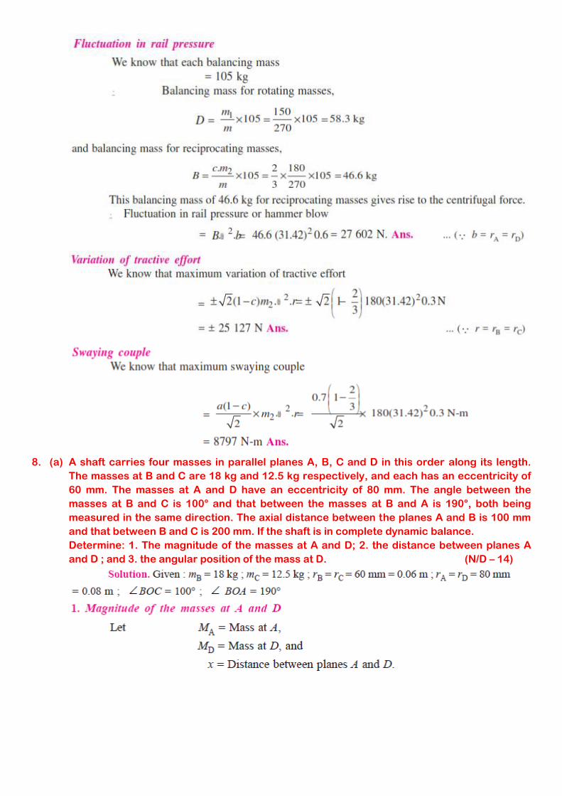
7. (b) An inside cylinder locomotive has its cylinder centre lines 0.7 m apart and has a stroke
of 0.6 m. The rotating masses per cylinder are equivalent to 150 kg at the crank pin, and
the reciprocating masses per cylinder to 180 kg. The wheel centre lines are 1.5 m
apart. The cranks are at right angles. The whole of the rotating and 2/3 of the
reciprocating masses are to be balanced by masses placed at a radius of 0.6 m. Find
the magnitude and direction of the balancing masses. Find the fluctuation in rail
pressure under one wheel, variation of tractive effort and the magnitude of swaying
couple at a crank speed of 300 r.p.m. (N/D – 16)
(16)

8. (a) A shaft carries four masses in parallel planes A, B, C and D in this order along its length.
The masses at B and C are 18 kg and 12.5 kg respectively, and each has an eccentricity of
60 mm. The masses at A and D have an eccentricity of 80 mm. The angle between the
masses at B and C is 100° and that between the masses at B and A is 190°, both being
measured in the same direction. The axial distance between the planes A and B is 100 mm
and that between B and C is 200 mm. If the shaft is in complete dynamic balance.
Determine: 1. The magnitude of the masses at A and D; 2. the distance between planes A
and D ; and 3. the angular position of the mass at D. (N/D – 14)

0.08 mD.x = vector c′ o′ = 0.235 kg-m2 . . . (i) In Fig. (b), draw OD parallel to vector c′ o′ to fix the direction of mass D.

9. (a) Four masses A, B, C and D as shown below are to be completely balanced.
- A B C D
Mass (kg) - 30 50 40
Radius (mm) 180 240 120 150
The planes containing masses B and C are 300 mm apart. The angle between planes containing B and C is 90°. B and C make angles of 210° and 120° respectively with D in the same sense. Find : 1. The magnitude and the angular position of mass A ; and 2. The position of planes A and D. (N/D – 11)
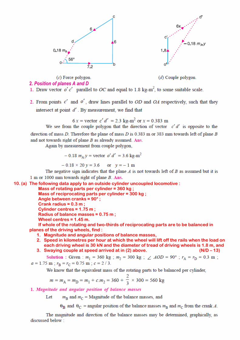
2. Position of planes A and D
10. (a) The following data apply to an outside cylinder uncoupled locomotive :
Mass of rotating parts per cylinder = 360 kg ; Mass of reciprocating parts per cylinder = 300 kg ; Angle between cranks = 90° ; Crank radius = 0.3 m ; Cylinder centres = 1.75 m ; Radius of balance masses = 0.75 m ; Wheel centres = 1.45 m.
If whole of the rotating and two-thirds of reciprocating parts are to be balanced in planes of the driving wheels, find :
1. Magnitude and angular positions of balance masses, 2. Speed in kilometres per hour at which the wheel will lift off the rails when the load on
each driving wheel is 30 kN and the diameter of tread of driving wheels is 1.8 m, and 3. Swaying couple at speed arrived at in (2) above. (N/D – 13)
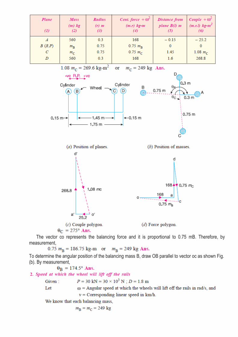
The vector co represents the balancing force and it is proportional to 0.75 mB. Therefore, by measurement,
To determine the angular position of the balancing mass B, draw OB parallel to vector oc as shown Fig. (b). By measurement,
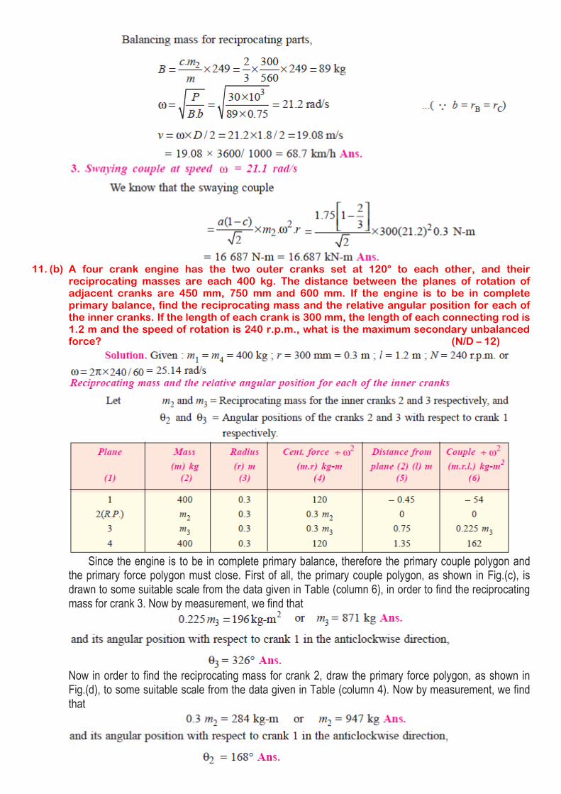
11. (b) A four crank engine has the two outer cranks set at 120° to each other, and their
reciprocating masses are each 400 kg. The distance between the planes of rotation of adjacent cranks are 450 mm, 750 mm and 600 mm. If the engine is to be in complete primary balance, find the reciprocating mass and the relative angular position for each of the inner cranks. If the length of each crank is 300 mm, the length of each connecting rod is 1.2 m and the speed of rotation is 240 r.p.m., what is the maximum secondary unbalanced force? (N/D – 12)
Since the engine is to be in complete primary balance, therefore the primary couple polygon and the primary force polygon must close. First of all, the primary couple polygon, as shown in Fig.(c), is drawn to some suitable scale from the data given in Table (column 6), in order to find the reciprocating mass for crank 3. Now by measurement, we find that
Now in order to find the reciprocating mass for crank 2, draw the primary force polygon, as shown in Fig.(d), to some suitable scale from the data given in Table (column 4). Now by measurement, we find that

Maximum secondary unbalanced force:
The secondary crank positions obtained by rotating the primary cranks at twice the angle, is shown
in Fig.(e). Now draw the secondary force polygon, as shown in Fig.( f ), to some suitable scale, from the
data given in Table (column 4). The closing side of the polygon shown dotted in Fig.( f ) represents the
maximum secondary unbalanced force. By measurement, we find that the maximum secondary
unbalanced force is proportional to 582 kg-m.
Maximum secondary unbalanced force
12. (b) The cranks and connecting rods of a 4 - cylinder in - line engine running at 1800 r.p.m. are
60 mm and 240 mm each respectively and the cylinders are spaced 150 mm apart. If the cylinders are numbered 1 to 4 in sequence from one end, the cranks appear at intervals of 90° in an end view in the order 1 – 4 – 2 – 3. The reciprocating mass corresponding to each cylinder is 1.5 kg. Determine: 1. Unbalanced primary and secondary forces, if any, and 2. Unbalanced primary and secondary couples with reference to central plane of the engine. (N/D – 11, A/M – 11)
1. Unbalanced primary and secondary forces

The primary force polygon from the data given in Table 22.10 (column 4) is drawn as shown in
Fig.(c). Since the primary force polygon is a closed figure, therefore there are no unbalanced primary
forces. Ans.
The secondary crank positions, taking crank 3 as the reference crank, is shown in Fig.(e). From the
secondary force polygon as shown in Fig.( f ), we see that it is a closed figure. Therefore there are no
unbalanced secondary forces. Ans.
2. Unbalanced primary and secondary couples
The primary couple polygon from the data given in Table (column 6) is drawn as shown in Fig.(d). The closing side of the polygon, shown dotted in the figure, represents unbalanced primary couple. By measurement, we find the unbalanced primary couple is proportional to 0.19 kg-m2. Unbalanced primary couple,

The secondary couple polygon is shown in Fig.(g). The unbalanced secondary couple is shown by dotted line. By measurement, we find that unbalanced secondary couple is proportional to 0.54 kg-m2. Unbalanced secondary couple,
13. (b) A five cylinder in - line engine running at 750 r.p.m. has successive cranks 144° apart, the
distance between the cylinder centre lines being 375 mm. The piston stroke is 225 mm and the ratio of the connecting rod to the crank is 4. Examine the engine for balance of primary and secondary forces and couples. Find the maximum values of these and the position of the central crank at which these maximum values occur. The reciprocating mass for each cylinder is 15 kg. (N/D – 14)
Assuming the engine to be a vertical engine, the positions of the cylinders and the cranks are
shown in Fig.(a), (b) and (c). The plane 3 may be taken as the reference plane and the crank 3 as the
reference crank. The data may be tabulated as given in the following table.
Now, draw the force and couple polygons for primary and secondary cranks as shown in Fig.(d),
(e), ( f ), and (g). Since the primary and secondary force polygons are close, therefore the engine is
balanced for primary and secondary forces. Ans.
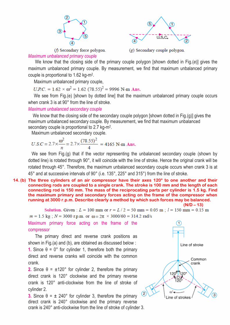
Maximum unbalanced primary couple We know that the closing side of the primary couple polygon [shown dotted in Fig.(e)] gives the
maximum unbalanced primary couple. By measurement, we find that maximum unbalanced primary
couple is proportional to 1.62 kg-m2.
Maximum unbalanced primary couple,
We see from Fig.(e) [shown by dotted line] that the maximum unbalanced primary couple occurs
when crank 3 is at 90° from the line of stroke.
Maximum unbalanced secondary couple
We know that the closing side of the secondary couple polygon [shown dotted in Fig.(g)] gives the maximum unbalanced secondary couple. By measurement, we find that maximum unbalanced secondary couple is proportional to 2.7 kg-m2. Maximum unbalanced secondary couple.
We see from Fig.(g) that if the vector representing the unbalanced secondary couple (shown by
dotted line) is rotated through 90°, it will coincide with the line of stroke. Hence the original crank will be
rotated through 45°. Therefore, the maximum unbalanced secondary couple occurs when crank 3 is at
45° and at successive intervals of 90° (i.e. 135°, 225° and 315°) from the line of stroke.
14. (b) The three cylinders of an air compressor have their axes 120° to one another and their connecting rods are coupled to a single crank. The stroke is 100 mm and the length of each connecting rod is 150 mm. The mass of the reciprocating parts per cylinder is 1.5 kg. Find the maximum primary and secondary forces acting on the frame of the compressor when running at 3000 r.p.m. Describe clearly a method by which such forces may be balanced. (N/D – 13)
Maximum primary force acting on the frame of the
compressor
The primary direct and reverse crank positions as
shown in Fig.(a) and (b), are obtained as discussed below :
1. Since θ = 0° for cylinder 1, therefore both the primary
direct and reverse cranks will coincide with the common
crank.
2. Since θ = ±120° for cylinder 2, therefore the primary
direct crank is 120° clockwise and the primary reverse
crank is 120° anti-clockwise from the line of stroke of
cylinder 2.
3. Since θ = ± 240° for cylinder 3, therefore the primary direct crank is 240° clockwise and the primary reverse crank is 240° anti-clockwise from the line of stroke of cylinder 3.

From Fig.(b), we see that the primary reverse cranks form a balanced system. Therefore there is no unbalanced primary force due to the reverse cranks. From Fig.(a), we see that the resultant primary force is equivalent to the centrifugal force of a mass 3 m/2 attached to the end of the crank.
The maximum primary force may be balanced by a mass attached diametrically opposite to the crank pin and rotating with the crank, of magnitude B1 at radius b1 such that
Maximum secondary force acting on the frame of the compressor
The secondary direct and reverse crank positions as shown in Fig.(a) and (b), are obtained as
discussed below :
1. Since θ = 0° and 2 θ = 0° for cylinder 1, therefore both the secondary direct and reverse cranks will
coincide with the common crank.
2. Since θ = ±120° and 2 θ = ± 240° for cylinder 2, therefore the secondary direct crank is 240°
clockwise and the secondary reverse crank is 240° anticlockwise from the line of stroke of cylinder 2.
3. Since θ = ± 240° and 2 θ = ± 480°, therefore the secondary direct crank is 480° or 120° clockwise
and the secondary reverse crank is 480° or 120° anti-clockwise from the line of stroke of cylinder 3.
This maximum secondary force may be balanced by a mass B2 at radius b2, attached diametrically
opposite to the crankpin, and rotating anti-clockwise at twice the crank speed, such that