M.E. 366-J Embodiment Design Project Portable Foot ... · The design team used the Paul Beitz...
49
NASA-CR-197163 NASw-4435 / M.E. 366-J Embodiment Design Project Portable Foot Restraint Team Members: Randall Heaton Eikar Meyer Davey Schmidt Kevin Enders - Team Leader April 25, 1994 (NASA-CR-197163) M.E.366-J EMBODIMENT DESIGN PROJECT: FOOT RESTRAINT (USRA) 49 PORTABLE D G3/54 N95-12361 Unclas 0026143 https://ntrs.nasa.gov/search.jsp?R=19950005948 2018-07-17T09:47:54+00:00Z
Transcript of M.E. 366-J Embodiment Design Project Portable Foot ... · The design team used the Paul Beitz...
NASA-CR-197163
NASw-4435
/
M.E. 366-J Embodiment Design Project
Portable Foot Restraint
Team Members:
Randall Heaton
Eikar Meyer
Davey Schmidt
Kevin Enders - Team Leader
April 25, 1994
(NASA-CR-197163) M.E.366-J
EMBODIMENT DESIGN PROJECT:
FOOT RESTRAINT (USRA) 49
PORTABLE
D
G3/54
N95-12361
Unclas
0026143
https://ntrs.nasa.gov/search.jsp?R=19950005948 2018-07-17T09:47:54+00:00Z
Abstract
During space shuttle operations, astronauts require support to carry out tasks in
the weightless environment. In the past, portable foot restraints (PFR) with orientations
adjustable in pitch, roll, and yaw provided this support for payload bay operations. These
foot restraints howe_r, were designed for specific tasks with a load limit of 111.2
Newtons. Since the original design, new applications for foot restraints have been
identified. New designs for the foot restraints have been created to boost the operational
work load to 444.8 Newtons and decrease setup times. What remains to be designed is an
interface between the restraint system and the extra-vehicular mobility unit (EMU) boots.
NASA provided a proposed locking device involving a spring-loaded mechanism. This
locking mechanism must withstand loads of 1334.4 Newtons in any direction and weigh
less than 222.4 Newtons.
This paper develops an embodiment design for the interface between the PFR and
the EMU boots. This involves design of the locking mechanism and a removable cleat
that allows the boot to interface with this mechanism. The design team used the Paul
Beitz engineering methodology to present the systematic development, structural analysis,
and production considerations of the embodiment design. This methodology provides a
basis for understanding the justification behind the decisions made in the design.
Background and Statement of Problem:
Due to the weightless environment of space, astronauts require support to carry
out their tasks. This means that a system of restraint is necessary to give them enough
leverage to carry out even simple functions. NASA has previously addressed this problem
with a portable foot restraining mechanism which can be moved about the payload bay.

However, tasks have been identified which require more and more leverage. It has
become paramount that a new restraining mechanism be designed to meet this need
NASA has developed a series of specifications for the new restraints. The means
of restraint needs to be portable and lock into various sections within the payload bay.
The amount of available space makes this necessary. The weight and volume must also be
limited so that the PFR is indeed portable and does not take up much space while not in
use,
The scope of the taskghe design team is limited to,design of the interface between
the PFR and the EMU boots. NASA provided a preliminary design for this locking
mechanism for the team to develop. Due to the requirement of the PFR bekig portable,
the,,/gc,ki,a_ mechanism Is limited to a wei_,ht o ¢222.4 New'aaas The dexterity of the
astronauts will be retarded due to their EMU's so operation of the locking mechanism
must be simple. Time constraints on missions also require that operation be quickly
accomplished in a maximum of three steps. The locking mechanism must endure loads of
1334.4 Newtons with a safety factor of 1.4 in any direction to properly support the
astronaut. Finally, since 8 units are required, the cost of the project is a factor. The
protot_e is limited to $350,000 and the- $125,000 per actual unit. Therefore, to meet
project cost ceilings, the system must work with the present EMU boots. The interface
design must include a removable cleat that attaches to the boot and locks into the PFR.
Other functional requirements are included in the specification sheet.
Scope and Limitations
The design of an improved PFR must solve certain problems. Clarification of
these problems begins with the major function of the device, securing the astronaut's feet.
The design must secure the feet in any direction and withstand a pull out force of 1868
Yewtor_ (factor of safety included). The design must also allow for easy manipulation of
tho task, as the astronaut will be using the device while wearing an EMU.
Another problem that the design must solve is to produce an interface between the
EMU boot and the proposed foot restraint. This requires that the design include a cleat to
attach to the EMU boot. This cleat must be able to withstand all forces specified for the
securing device without hindering agility.
There are several important issues to be considered in the design of a more
effective PFR. First, the device must be sturdy. It will need to withstand not only the
forces applied by the astronaut, but also the forces involved in take off and re-entry. The
device must also be light, as the cost of sending mass into space is high. Also, NASA has
existing standards for the geometry of the EMU boots to which the design must conform.
In addition, the design can not damage or pinch the boots in any way, as this could lead to
safety problems. The materials used in the design will also be of great importance.
Finally, the device must operate in a wide range of temperatures (-171 to 111 degrees C)
and be corrosion resistant.
The proposed embodiment design that follows will be limited to the design of the
foot restraining mechanism and the cleat. These parts will interface with the existing
NASA PFR support structures shown in the appendices.
Functional Description of Portable Foot Restraint
Embodiment Determining Requirements
The existingdesignfortheportablefootrestraintconsistsof a springloaded
mechanism analogous to a snow ski binding. NASA engineers want to incorporate this
basic concept into a new, higher performance design. The new set of specifications
NASA has developed for the portable foot restraint comprises the guidelines on which the
following embodiment design will be based.
NASA has decided on a set of concept requirements to which the design of the
portable foot restr_nt must ad_tere. First, the device must secure the astronauts foot with
some sort of a spring loaded system. This is similar to the e._sting design bo: n,ust be
improved upon ,Mso the securing device muu include a removable cleat which can be
attached to the bottom of the EMU boot.
The specification requirements of the embodiment design can be seen by examining
the attached specification list. Some ol_these warrant brief discussion.. The most important
requirement of the new design is that it be able to withstand 1334.4 Newtons in any
direction, without the astronauts foot slipping free. The existing design was weak in this
area, and the astronauts often r_und it too easy to inadvertentl'_ unsecu_ Eneir feet from
the restraint. The new design must also be easy for the astronaut to manipulate while in an
EMU. The quantification of this specification is that the user be able to work the device in
.t,hree,or.le_ steps. The design must also conform to the existing EMU boot
specifications, which affects the design of the cleat that must attach to the bottom of the
boots. Finally, it is important that the device not damage or pinch the boot or any other
portion of the EMU. The following design follows all of the constraints listed above as
well as the_specifications presented in the/sp_ecification list.
Discussion of the Presented Embodiment Design
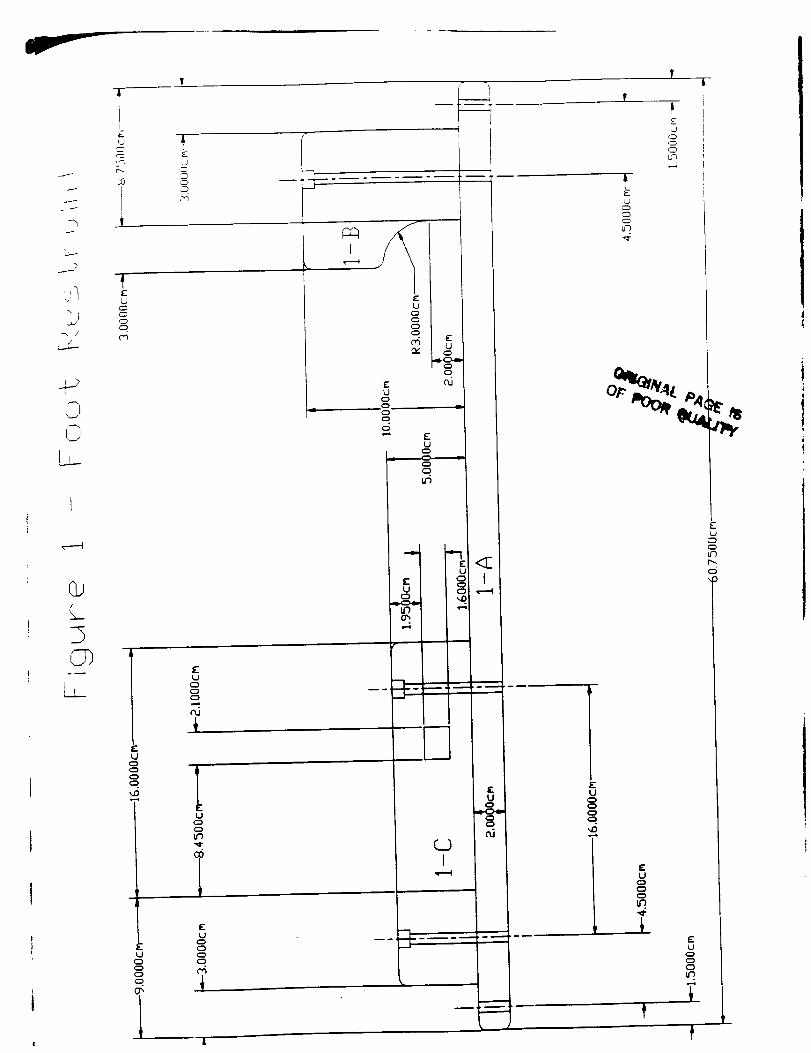
The embodiment design agreed upon by the design team is presented in Figures 1
through 22. These figures eO_ ot'a side and a top view of the restraining mechanism, a
schematic of the restraint release system, and a side and top view of the de, at, and several
views of the release and pulley mechanisms.
Embodiment Concept
Prior to discussing the details of the actual design it is important to discuss the
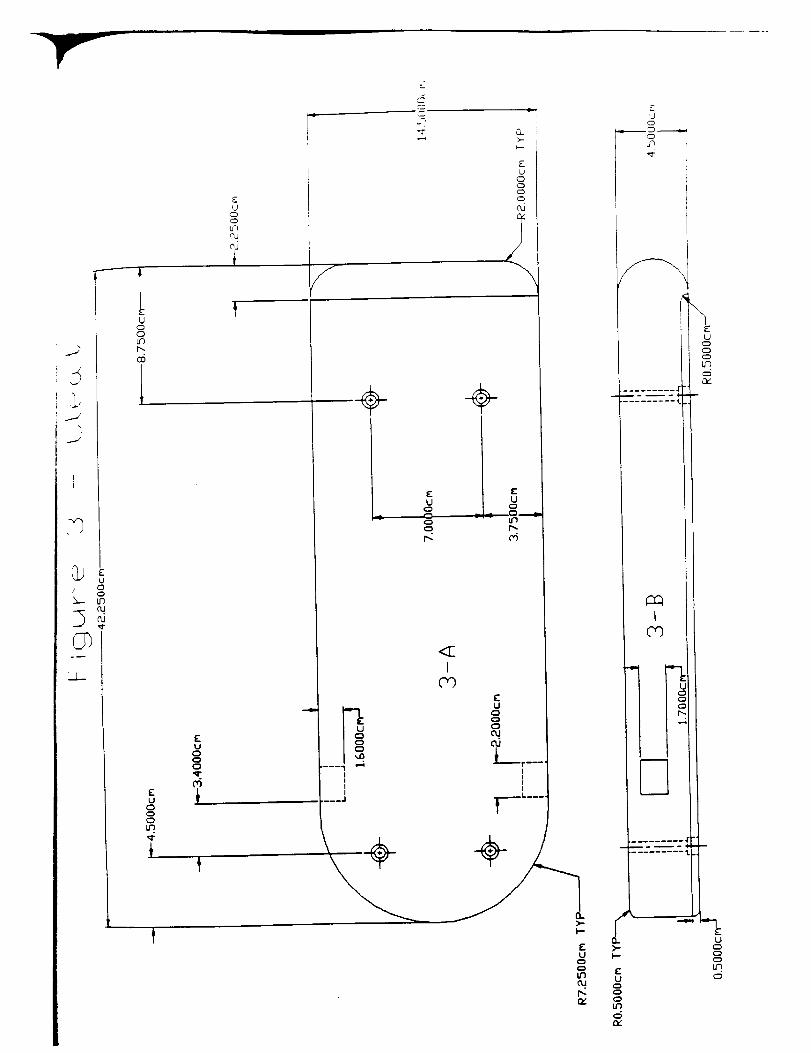
concept proposed for the PFR. The first step is to secure the designed cleat (Figure 3) to
the bottom of the EMU boot. The astronaut then places the front end of the cleat under
the toe support (Part 1-B in Figure 1) and steps down with his or her heel. As the
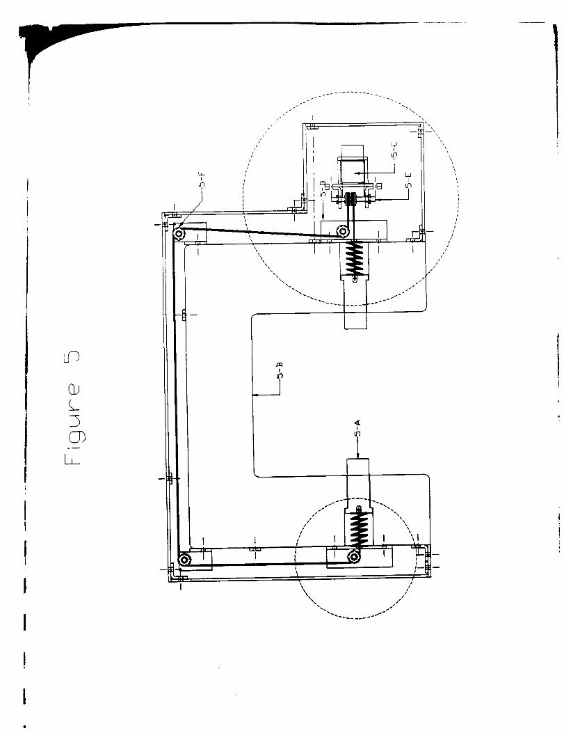
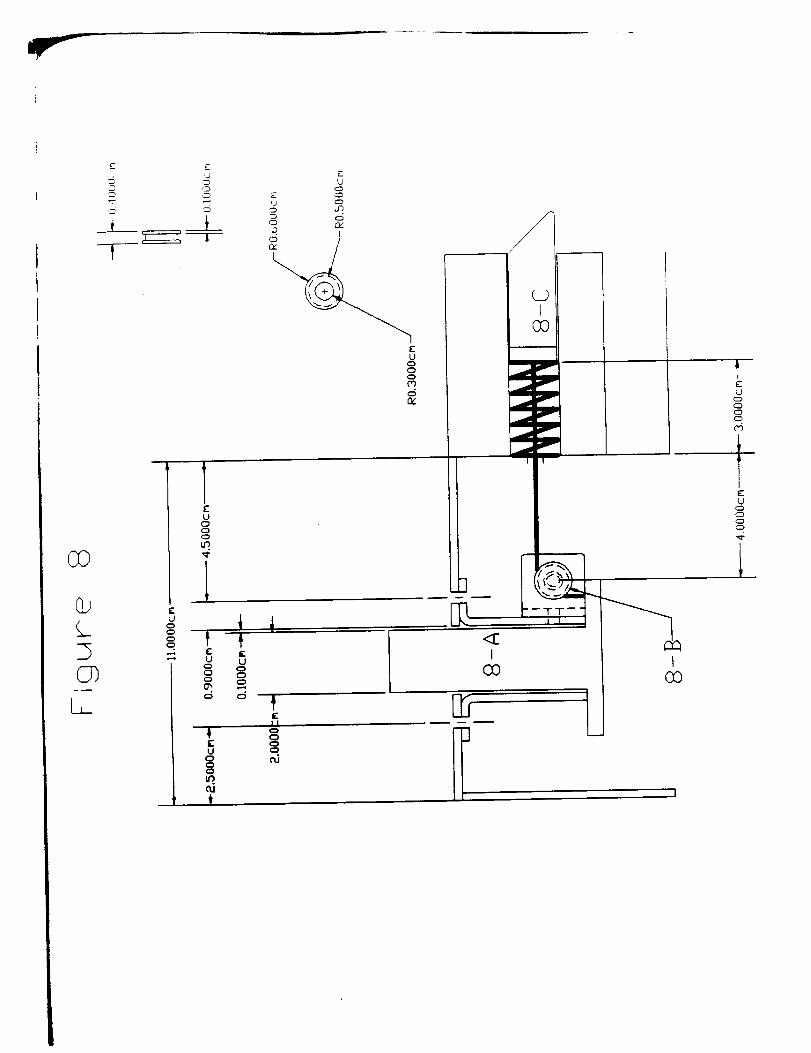
astronaut puts weight on his or her heel, the spring loaded securing pins (Part 5-A in
Figure5) protrudingfrom thesidesof theheelclampareforcedoutward Thepinsare
machinedat a forty five degreeangleasseeninFigure8 (Part8-C). As theastronaut
stepsdown,hisor herweightforceisappliedin bothverticalandhorizontaldirectionsdue
to thisgeometry.This forcesthepinsto retractagainstapairof internalsprings(Part6-A
in Figure6, Part7-A inFigure7). Whentheastronaut'sfoot is in its properposition,the
springsejectthe pins into the machined holes on either side of the cleat. This restrains
movement of the foot in the vertical direction. Any movements in the horizontal direction
are restrained by the combination of the toe support and the heel restraint.
To release his or her foot, the astronaut pushes a release button (Part 5-C in Figure
5) that is connected to the securing pins by a taught wire (shown in Figures 5-8). When
the button is pushed, the securing pins are pulled back into their retracted positions,
allowing the astronaut to free his or her foot. When the button is released, the springs
expand and the securing pins are ejected to their original rest positions.
Discussion of Individual Embodiment Components
The discussion of the indivkhaal components involved in the proposed design
begins with the base plate and restraining supports shown in Figure 1. The base plate
(Part l-A) must be designed to attach to the PFR work site interface. This is
accomplished by bolting the plate through the extended flanges at either end of the base
plate. Six quarts¢ inch socket head cap screws (round heads) will be used as fastening
mechanisms. These bolts, while being much stronger than necessary to secure the plate
(see calculations), are easier to manipulate than weaker bolts. Their round head _lso
allows them to fit nicer into round eounterbored holes. The plate will be made of 6061
aluminum, which will withstand all foreseeable ioads (see calculations). 6061 aluminum is
also exceptionally machinable and can easily be fabricated from sheet stock, using a mill or
drill press.
Attached to the base plate is the fi'ont toe support (Part l-B) and the heel restraint
(Part I-C). Both pieces must be able to withstand the specified load and will be secured
using quarter inch (1/4 -20) socket head cap screws. The material suggestion for the toe
support is 6061 aluminum This aluminum can be both machined or die cast, the two most
likely methods of fabricating this difficult geometrical part. It is also strong enough to
v, ithstand the specified load.
The heel restraint can be seen in as part I-C in Figure 1. This part will serve as the
spring loaded restraint that will secure the astronaut's foot firmly in place. The restraint
will be held to the base plate by five quarter inch (1/4-20) socket head cap screws. A
material suggestion for this part is 6061 aluminum. Manufacturing of the part woutd
involve milling the main geometry, then using electric discharge machining to produce the
square holes on either side of the restraint.
Figure 3 shows a top and a side view of the proposed cleat design. The cleat is
dimensioned to fit the existing specifications of the EMU boot. The important aspect of
this cleat is that it must be able to mount to the bottom of the EMU boot and withstand
the specified load. This will be accomplished with four socket head cap screws. These
bolts will thread into the fiberglass plate found on the bottom of the EMU boot. The cleat
could be made of 6061 aluminum which will be strong enough to withstand the load and
not add a great deal of weight or bulk to the EMU. Also the aluminum will resist possible
cold welding with the toe support.
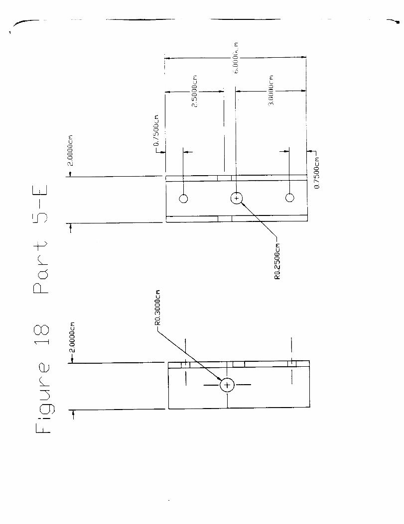
Figures 4 through 8 show the release mechanism and the securing pins. A better
drawing of the pin design is shown in Figure 16. Th()se pins will be the most important
part of the design, as they will secure the foot into place when they ate ejected imo,the
square holes on either side of the cleat. Not only must these pins be designotl to withstand
the specified load, they must also slide inside the holes m,_hined in the heel restraint. This
means metal to metal contact. Another important constraint of the pins is that they must
be abrasion resistant, as they will be in sliding contact with the bottom of the cleat. The
pins could be fabricated of anodized 6061 aluminum. Anodizing will improve surface
hardness and increase abrasion resistance. The anodizing does cause minor expansion in
the part however. If this expansion proves to be a problem, 303 stainless steel could be
used instead.
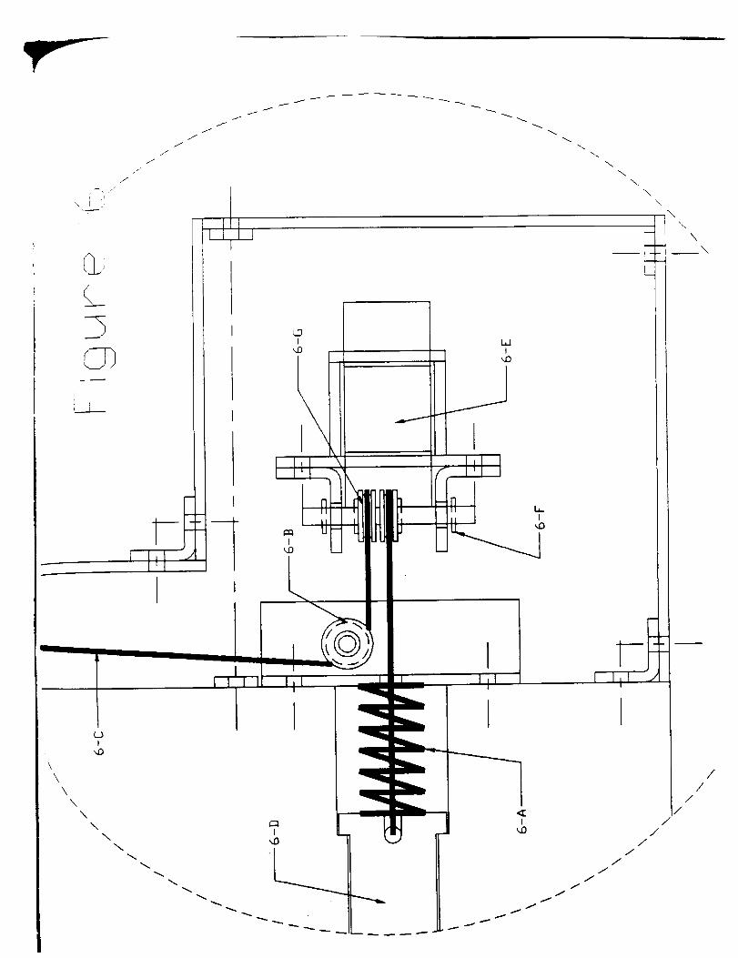
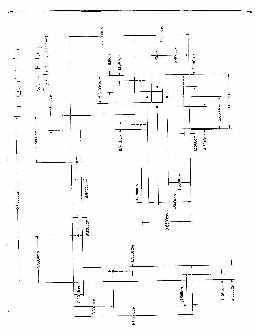
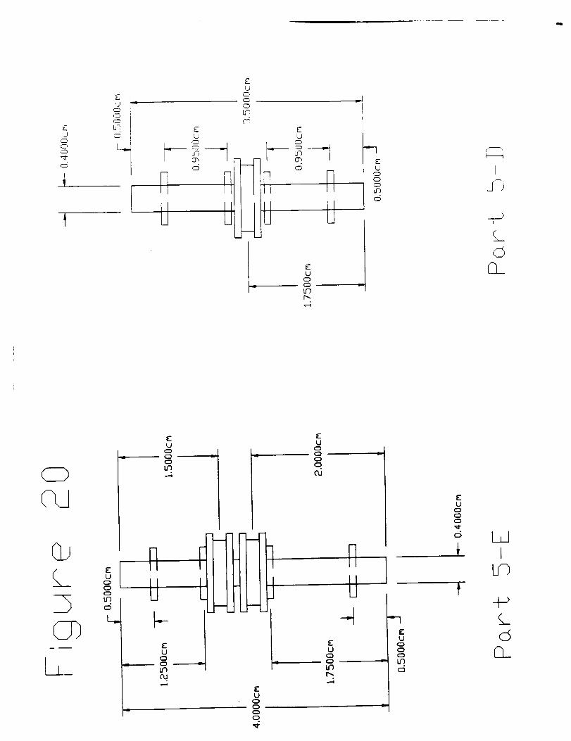
Figures 6 and 7 show blowup views of the release button and the pulley system.
These pulleys (Parts 6-B and 7-B) could be machined of a lightweight aluminum, either
6
3003or 6061,andwouldbeheldon thesupportbarwithdowelpins(Part7-F)asshown
inFigure20. 6061 aluminum could be used as a material option for the button itself(Part
6-E). A suggestion for the wire used to retract the pins is 1.59 cm (1/16 in.) 7x7 aircraft
wire. The wire will be connected to the securing pins by looping the wire around a hole
machined in the pins (part 6-G) then fastening the wire back on itself with a crimp. Finally
the spring (Parts 6-A and 7-A) could be made of piano wire and have a recommended
spring constant of roughly 350 Newtons per meter.
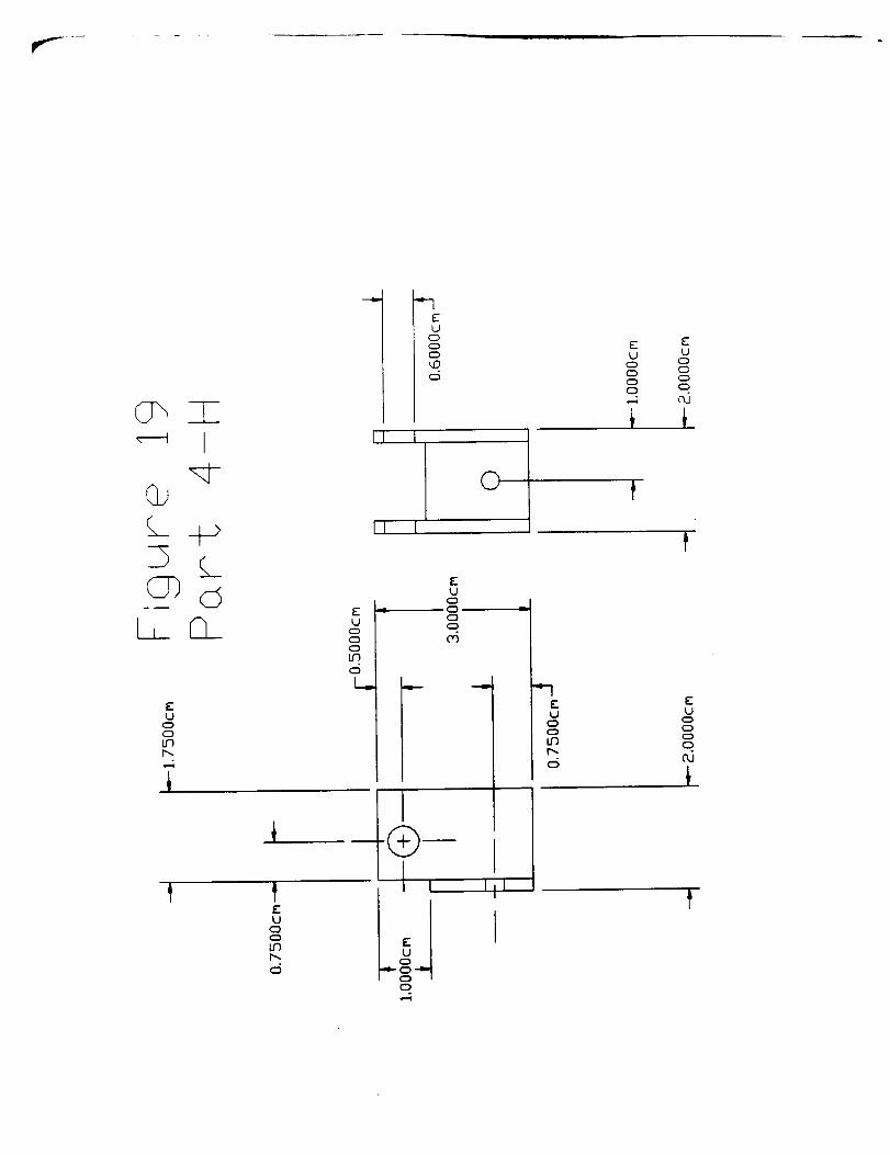
The pulley system rests inside a sheet aluminum housing which is secured to the
outside of the heel restraint as shown in Figure 4. Size 5 bolts (1/8 in.) will be used as
fasteners to keep the housing in place, with angle brackets connecting the individual sides.
This housing will encompass the wires and pulleys on all sides except the bottom, forming
a protective shell.
Overall Design Analysis
It is the opinion of the design team that the proposed design satisfies the
specifications setup by the NASA engineers. The calculations that follow show that the
design presented will withstand the 1868 Newton force applied in any direction without a
problem. The only possibility for failure due to this force would be caused by either
internal or external cracks in the individual parts of the design. This type of defect could
lead to unforeseen fast fiacture. The use of aluminum to make the majority of the parts in
the design will keep the overall weight low, well below the 222.4 Newton maximum, as
well as offer good corrosion resistance, rhe aluminum also suffers lit'de _om thermal
expansion. The presented design allows for use in less than three stvps by the astronaut,
and should not damage or pinch the EMU boots in any way. Finally, since the majority of
the components of the design are ready a,¢_able _d _',_uld not prove difficult to
fabricate, the overall cost of the proposed PFR will be low.
This proposed design has many advantages over the existing PFR design. First,
the astronaut's feet will be secured much more firmly, and there should be no problem
with them becoming inadvertently unsecured. The proposed design is also easy to use,

requiring a minimal amount of steps to manipulate. Using socket head cap screws as
fasteners should also facilitate the transportation of the device from position to position in
the cargo bay. Finally, fabricating the device from a high strength aluminum alloy makes
it lightweight and corrosion resistant.
The proposed design does have a contain a few drawbacks. The astronaut's feet
will be firmly secured and he or she will not be able to pull them out until the button
release is actuated. This could lead to possible safety problems. Also the cable release
system is not as sturdy as the other components in the design proposal. The design team
does not f_l that the release system will pose any problems in terms of reliability, but it is
the weakest portion of the device.
Calculations
As mentioned earlier, the specifications demand that the PFR withstand loads of up
to 1868 Newtons in any direction (safety factor of 1.4 included). The design team
therefore performed calculations confirming that the proposed design will withstand the
designated loads.
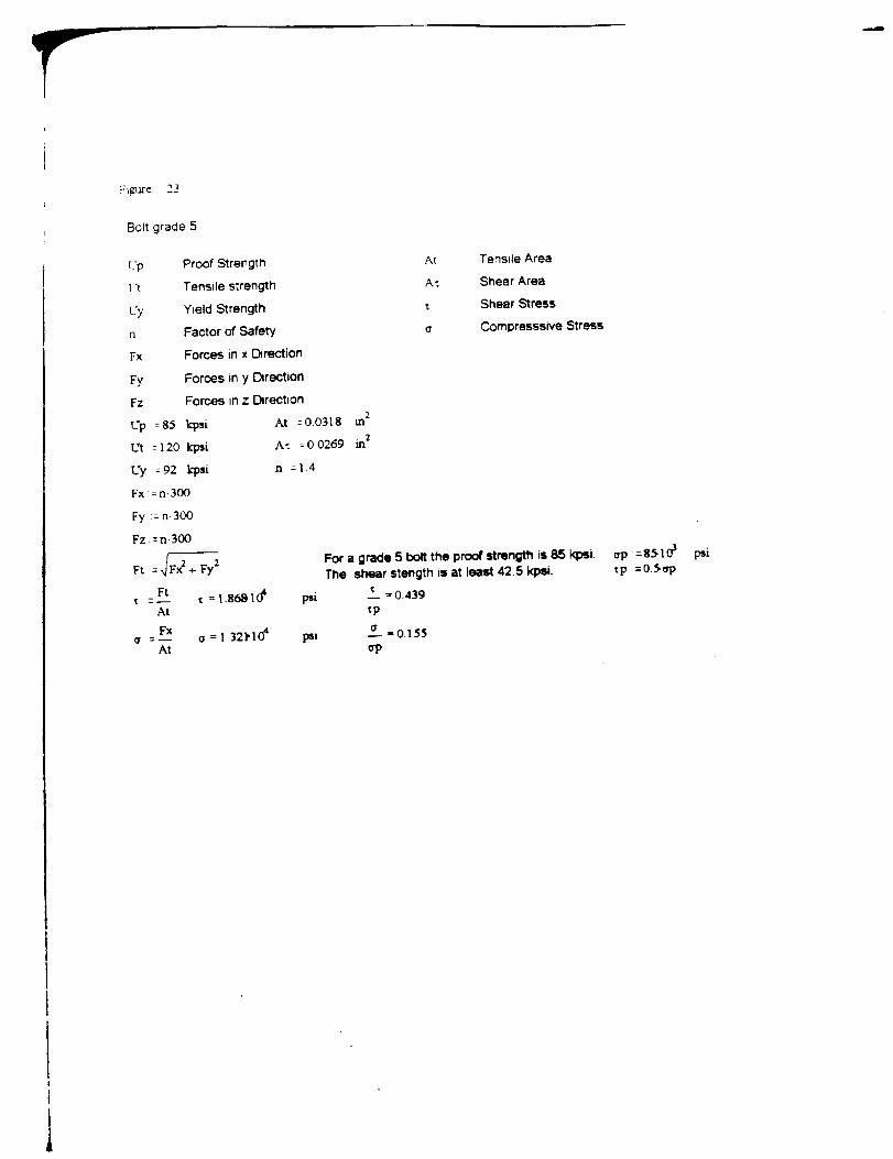
Figure 23 shows the calculations addressing the bolts that attach the cleat to the
EMU boots. These calculations were performed under the assumption that if a single bolt
can support the required load, then obviously a group of the same type of bolts could do
the same. Examination oftbe numbers shows that one grade five bolt will withstand the
load in both tension and in shear. The actual design uses four socket head cap screws to
secure the cleat to the bottom of the EMU boot. Since the proof strength of a socket
head cap screw is superior to that of a grade five bolt, there should be no problem in
supporting this load. To minimize the risk of failure due to unforeseen moments or fast
fracture, four socket head cap screws will be used instead of one. The analysis discussed
above can be applied to all loaded bolts in the proposed design. For this reason there will
be no further calculations done on failure of the bolts.
Figure 24 shows calculations addressing fatigue loading of the bolts. Again the
analysis is done using the physical properties of a grade 5 bolt. Since this bolt will
vdthstand the fatigue loading, it is inherent that the socket head cap screws used in the
existing design will also withstand fatigue loading.
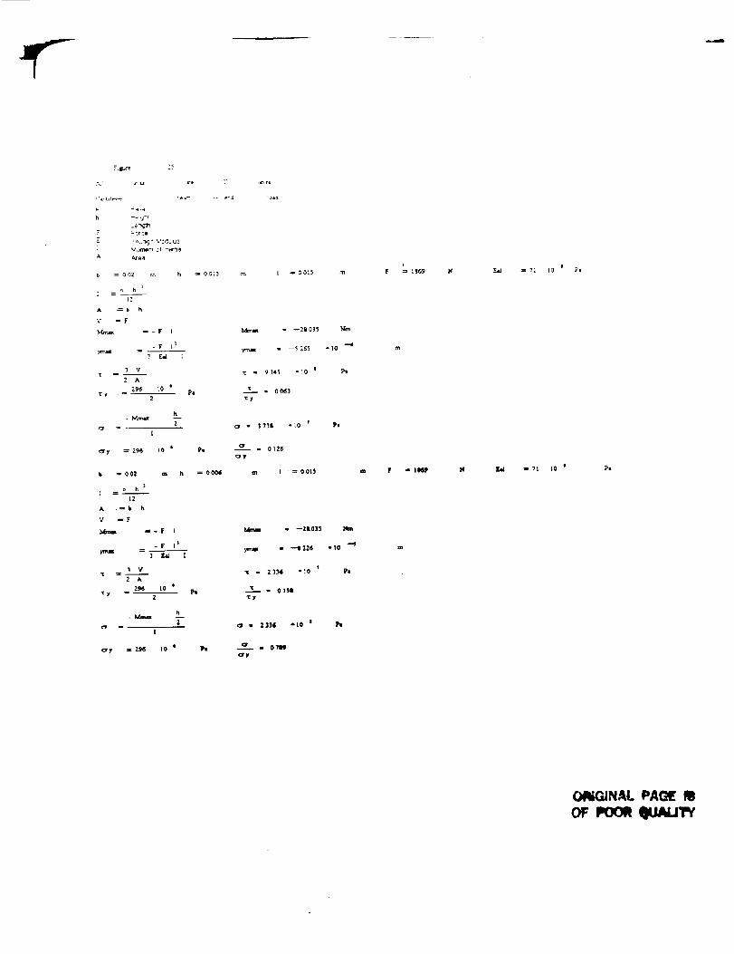
The most important calculations for the PFR design are presented in Figure 25.
These are the calculations addressing the viability of the securing pins that hold the
astronaut's foot in place. In the calculation of the strength of the pins, the design team
used a worst case scenario approach with respect to shear and bending. The system was
considered as a cantilever beam with a point load of 1868 Newtons applied at the far end.
The material properties used were that of 2024 aluminum (inferior in strength to the 6061
suggested). Also only the minimum height of the pin was used for cross sectional area
calculations. The calculations show that the pin is satisfactory even in this worst case
scenario, validating the soundness of this portion of the design.
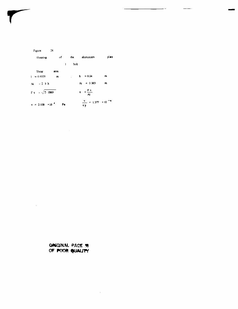
Figure 26 shows the calculations with respect to the base plate of the PFR. This
plate was analyzed against shear failure. Examination of the numbers show that.even with
the conservative analysis presented (one bolt was used instead of six), the plate withstood
the specified load.
Figure 27 shows the calculations used for checking the choice of spring and spring
constant. The value set for actuation of the button release mechanism was 7 Newtons. It
can be seen that a spring constant of about 350 Newtons per meter is acceptable.
Other calculations are presented in Figures 28 through 30. These include analysis
of the fiberglass plate on the bottom of the EMU boot, a calculation ¢,fmass, and a
strength analysis of the wire used in the release system. Examination of_hese calculations
validate the proposed design of the PFIL
Conclusion
It is the opinion of the design team that the proposed design detailed in this
document satisfies all existing requirements listed in the attached specification list. The
design should produce no difficulties in the areas of material availability or fabrication.

Future work involved in this design includes the production and testing of a
working prototype to confirm the analysis completed. The present embodiment may
prove to be over designed, and further analysis could be conducted to minimize material
waste, Other analysis could be done to locate stress concentrations and possible failure
positions using Finite Element Analysis. Also, more research could be conducted in the
areas of effective manufacturing and material selection
10

References
Budinski, Kenneth, Engineering Materials: Properties and Selections (Englewood Cliffs,
NJ, Prentice-Hall, 1992).
Juvinall, Robert, Fundamentals of Machine Component Design (New York, NY, John
Wiley & Sons t 991)
Schey, John, Introduction to Manufacturing Processes (New York, NY, McGraw-Hill
Inc., 1987).

Appendix A
Technical Drawings

In reference to the bolt holes shown in the following figures, the bolt holes shown
in Figure_, 1,2, and three are for quarter inch socket head cap screws The counterbored
holes have been counterbored 075 cm. All of the screw holes in the rest of the figures are
for size 5 bolts. The holes drilled into Part 5-C (Figure 5) for the size 5 bolts are drilled
0.5 cm into Part 5-C.

Quick Reference List of Parts and Fi2ure_s
Figure Numberl
Part Number1-A
1-B
1-C
Part NameBase Plate
Toe Support
Heel Restraint
2 2-A
2-B
2-C
Base Plate
Toe Support
Heel Restraint
3Cleat
Cleat
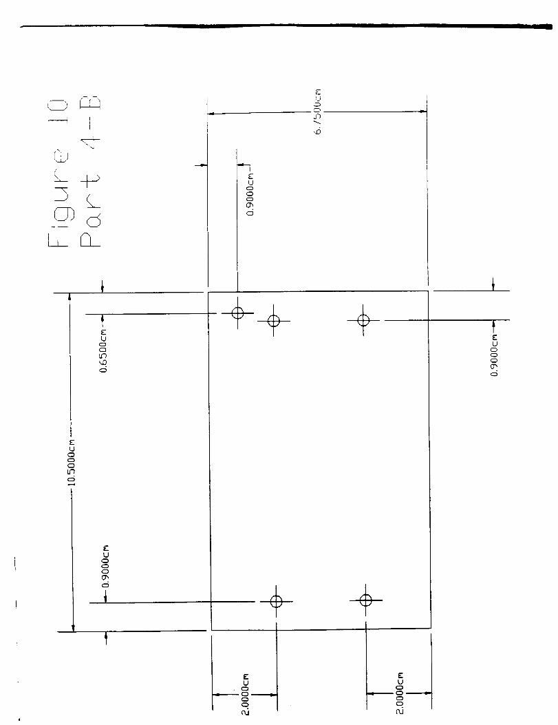
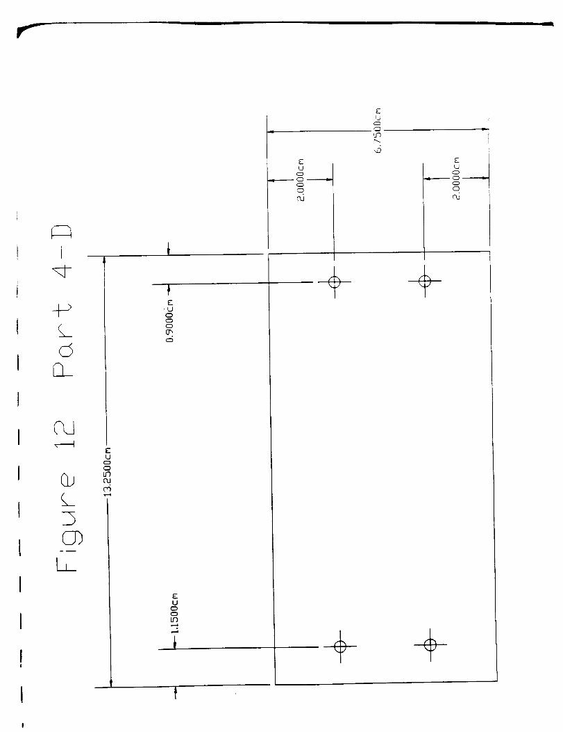
4-A
4-B
4-C
4-D
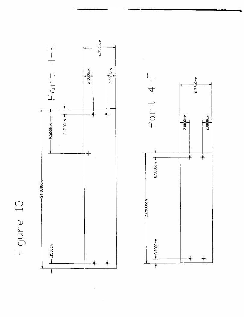
4-E
4-F
4-G
4-H
4-1
Aluminum Housing
Aluminum Housing
Aluminum Housing
Aluminum Housing
Aluminum Housing
Aluminum Housing
Alminum Housing
PulleySupport Flange
PulleySupport Flange'
5-A
5-B
5-C
5-D
5-E
5-F
Restraining Pins
Heel Restraint
Release Button
Pulley Support Flange
Pulley A
PulleyB
6 6-A
6-B
6-C
6-D
6-E
6-F
6-G
Spring
PulleyWire
RestrainingPinRelease Button
Dowd Pins
PulleyA
7 7-A
7-B
7-C
Spring
Pulley
RestrainingPin

9
10
11
12
13
14
15
16
17
18
19
20
21
22
8-A
8-B
8-C
Release Button
Pulley
Restraining Pin
Alurmnum Housing
A/urmnum Housing
Aluminum Housing
Aluminum Housing
Aluminum Housing
Aluminum Housing
Wire/Pulley Housing Cover
Release Button
Restraining Pin
Pulley Support Flange
Pulley Support Flange
Pulley Support Flange
l_lleys
L - Clamps
L-Clamps
J
.t>
00
@
LL_
II
4J
p...
so
U
C_
C_
UC_o
U
_o
T
4
J
C_
U
C_C_
OJ
i
U
a_
U
C_
L
I
-1
TL
!j
u_
uc_c_
Lf)
_E
U_P
U
C_
U
0

.4....._ D
(..a......
A-_>
+->00
L
OS
C9
L._
A.
÷ X÷ +
IOd
G,.),-
-.q}-
Q,.
£
(J, ÷cu
+
>..
u
o
...... .r ........
q_, I.n
÷
+
F
l.l
c_
A_ r_c_
lJ
_J u
Ln
C_
UC3
C_
qq-
U
(3
Q
_r ii
I
,J
U_
L.I
LF_
rv
I
ii
I
-''-L0. U
I:" Lr)
u c5
P,F

V-
f
L.)
U_
C_
]g
CDC_
('_
_JI
rm,
.].i
i ij
i i
ij
_J
E
L.)
C_
Lf)
TL
i
I i
]L
E
LJ
_rr_
LJc_
I I
I
L6I !
II
L_
C_
U_POO
C_
C)
L_C_
o_
g
C_
COL.J
C_
C_.
OW
U
U')
(%J
\
L
u_
I
\
i I
\ ,'
i
,,D
\
\\\\\
\
J
JJ
_J
\
J
J
iI
J
I
I
I
I'I I
I
Jf
If
J
JJ
\
JJ
\
\
\
\
//
/J
\
//
//

©
I,
J
J/
/
./
//
II
II
II
Jf
\\\
C.D
r_
\f
fKI
I
iii
mi
r_
\\
\
\\
\\
\\\
t
IIt
/t
\ /\ I\ I\ I\ /
\ I\ I
\ /J
JJ
fJ
E E
_j
-IEOOO
LEU
° _,
O
o
PtEU
O
_ _IL
E
U
E C;,
O
ELJ
OOO
J
]
01
PP
i
PPPPI
---l'T---]lI
U
c_
II
O0
<EI
CO
If- L.J
E
U
('6
u
I
03
, ],J.

LL_CL
p
uc_
C_
cr_
u
C_c_
uG
C_
uC_c_C_
c_
u
c_
L_r_
IJ
C_
u
C_
Ln
uC_
C_
Illlll
--_ C=_qi
©
N
EU
Lr),.p
Oc_
U
C_
tJ
L_
EU
c_C_
Gh
÷+
÷
c_
u
(=)
_J
uc_0C)(7'

D__LJ
tJ-)p...
EU
C_c_
CO
EU
c_O_
c5
EU
c}
t--4
,,-,,,4
EU
______ _ -----,-c_
Pd
EU
_ __m.ll.c_
_J
,--_ (_D
Q_
(.4_>
LL C___
II I
I
+->
©EL
±DC_
I,
EL.JOo(D
c5
EU
O
OIf)OJ
03
EU
OO
t
I
EU
o
oO
OJ
S'-U
U'hr'--.
UO
)-
O
CD
OJ
+
ii ___, 1.
GJ
3(2])
£
L.I
0
T1=U
C:l
Cl
G_
1
t:U
in
£
U
,4
E
,j
p_
£ _-
U U
...g... ,,.g...
cd c_
+
+ +
+ +
I
+-_L_(5
u
C_
T
EU
o
LC)t_
E: EU U
ai aJ
+ +
+ +

_ t
CY_©L_L_Q_
UcDc_DCDc_C_
EU
c:DCDc_
c_
Uc_
CDCY_
EU
oL._I"--
UcD
,,IS.m..m,- C_ _
C_
UCDC_t_
f II
, : j
!±j
_x_
m.t
I
L__
I.J
0
C7_
IZ
C_
CO
..j 0_ _ z i
_J
L3_. _\ ©
C _
U
_JC_
C_
IU
c_
t 1
t°_u
E
d
c_
U
C_C_
Izu
'.D
I.J
q_
a6
I_l
0_
C_
oj
I
w_
IOw
U
C_
L_
T..
E
U
Ii
!.1 :' I
U _J
U
O.J
, fi I
u
u
_D
U
c_oa_
°
I
T_. .._
2-
_ E
U
_0
uc__D
u-)o
,lC_
_J
C_

-4I
EU
hU
FU
Iu
_ c5_ c5F t_, ]
3U
©
U
n_
EU
9m------ O _
Ln
/i
/
/
U
c5
L.
u
•he-.- O --_m
-'m
LJ
LF_
c5
EL
COc-°_
c-
©
q_
Ul
FY
_3
O_
O}
LL
u
uC_O
U
©
UC_
C_
ai
u
"n
u
0
c-O
4_4_5m
(_
d(_
(_r_

EU
0
uCD0o
9_
L_©
L__G__
EU
L_
L...
EU
E EU U
U
qLl
U
'IIii
LLdI
LF)
H->
C_[D_
DCT)
I,
uCD(DCDCD
OJ
LJO
c_
OJ
FU
C)c_LC)
c_L..
U
c)oCY)c_rl,"
F_L)
C_
Lr)
CU
id
c)
FLJ
F
c_
(
EL)
C)U')
O
I
r
C_
C7)-- I
Eu
oI,n
c_CL_
EU
0
ob_c_L_.
U
cDLr_
c_
Uooo
0
I1 I
UcD
cD
O_
©
Uoooo
i
Ei.i
o
t_.
U0
ooo
0.J
EU
o
o
('U
UCD
_T
_J 11_-
h-I
'h
F-U
o
FU
Ln
c_
(ZD
c_
lI
EU
rr--_I
EU
c_
r--J
EU
c_c_Lr)
CL
CD
OJ
©±
CT)
L_c_C_c_
I---
U
° LI '°L. _- -
Uc_
,,--6EU
o
c_
It"LJ
c_
c_
Ud
Uc_c_
.,4
EU
0
c_
d
c_c_
--- I_
c_
r_
I,II
LrO
(.c_
[3__

z-
L I
EU
CD
.::D
0a
EU
G
£U
c_
c_I.n
£u
U c_
c_
() t--
I I
u
,,D
C_
EU
o
__i_
l-
U
o
o
EU
0
EU
0
c5
i
I2,,3 P-_
__ L__J
EU
O
t,D
i
I E
U
(
EU
cD
)
©
EU
O
ID,,4
I I I
Eu
c)_D
G.I
1
EU
G
c_

Lj_
C_
I, ]
EJooo
U<DooCD
_r
EUCDCDU9CU
EUO
F °U0O4
i
Uoooq)
O
F
UcDoCDU9
c5
UocDoU9
U
.m.--m O ------e..c_
_- U_U .__<DcD<D_.0
EUCDoCDo
EU
0
oo
o

r'--
Appendix B
Calculations
Flgt_e 23
Bolt grade 5
[5p Proof Strer_gt _ At
['t Tensile strength A.:
Uy Yield Strength t
n Factor of Safety _r
Fx Forces in x Direction
Fy Forces in y Direction
Fz Forces in z E_rect_on
. 2L'p --85 k-psi At--0.03t8 m
• 2Ut --120 k'_i At =00269 m
L'y =92 k'psi n =1.4
Fx:= n.300
Fy := n.300
Fz.--- n300
FL :: _ ÷ Fy 2
Ft- _ = 1.86_t04
At
Fx = 1 321.1o4At
Tensile Area
Shear Area
Shear Stress
CompresssNe Stress
For a grade 5 bolt the proof strength is 85 kq_i.
The shear stength is at least 42.5 kp=i.
psi _ = 0.439_P
_rl:_l -- = 0.155
o'p
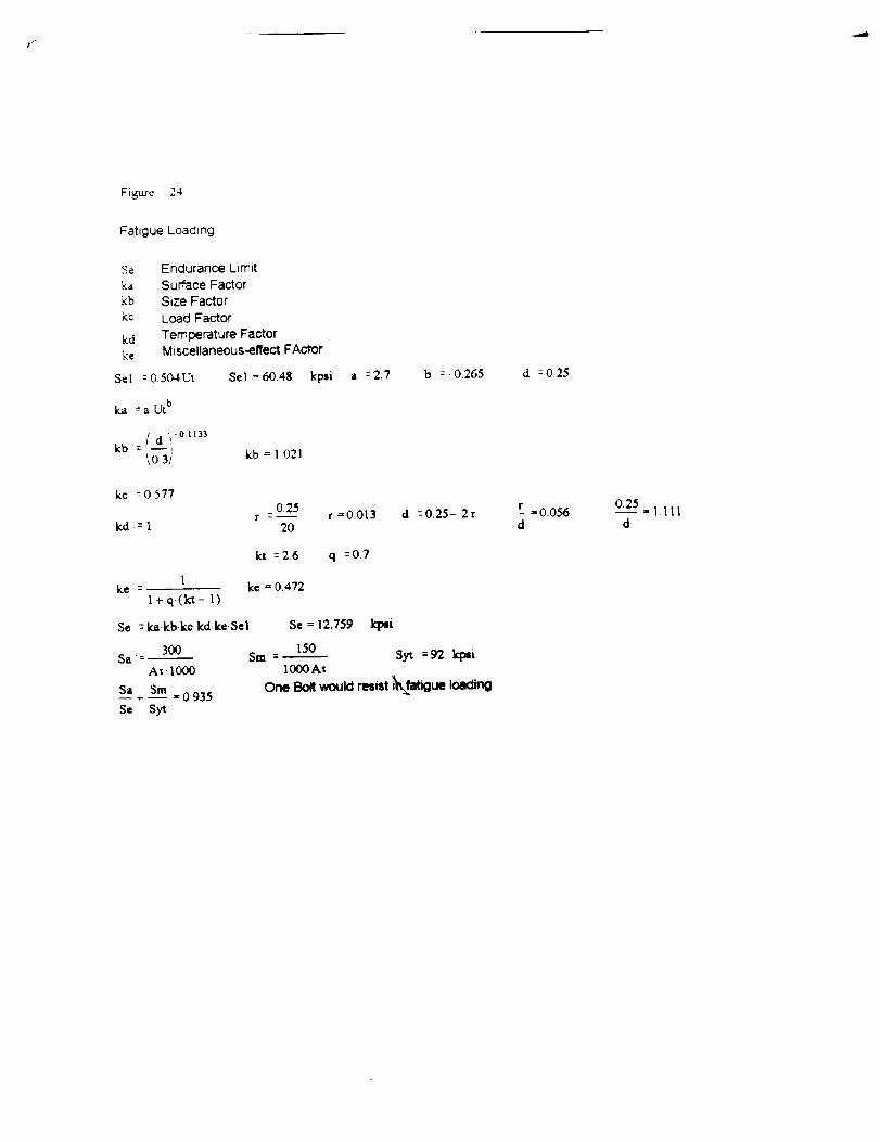
Figure 24
Fatigue Loading
Se Endurance Limit
ka Surface Factor
kb Size Factor
k.¢ Load Factor
kd Temperature Factorke Miscellaneous-effect FAclror
S¢I := 0.504UI Sel =60.48 kpsi
ka -- a. Ut b
a =2.7 b :- 0.265
kb = 1.021
kc :0 577
_ 0,25r ---
kd-=l 20r =0.013 d =0.25- 2r
kt --26 q --07
1ke = ke = 0.472
1 + q.(k't - 1)
Se :ka kbkc.kdkeSel Se = 12.759
300 150Sa:- Sm -
A_.I000 1000A_
Sa Sm+ -- = 0935
Se Syt
k_i
syt =_ iq:.i
One Bolt v_uld resist i_faboue loading
d = 0.25
r = O.O56d
0.25 = l.llld
F:i.rc 2-<
A Aze_l
- er_
b _ 002 m h _ 00;}
Jh
12
A _b h
V =F
-F L_
vi[
2 X
T# _ Pe2
h
e][
,O"y _ 296 10 J Pl
b = 002 m h = 0006
}b h
12
A .=b h
V --F
-F I I
3 V"
296 tOT y Pm
2
h- Mm_
2
!
<:Ty _ Z_ t0 i Pe
m I = 00_ m
_-_ . --211 0i$ _m
lc - 0 063
c:_ - $711 *t0 'I iill
m I _ 0015 m lr = II1_
ymal - "-tl 226 • I0
1"[ - 2336 "10 Pl
- 0i$1
_y
o' - 2114 -tO I llli
. 0 ?lill
,o'y
i.E.id = 71 I0 Fi
tl.il n 11 I0
ORIGINAL PAGE m
i
Figure 26
Shcartrtg
Shca]f _¢a
1 = 00375 m
At =2 l-h
F'¢ : .,"/_1869
x = 2.038 ,tO ,i
of
I
PI
rh,.
bolt
a]u11%l/tlllm
h =0.04 m
At _ 0003 m
Fxi: -
At
r 1377 • I0
-,:y
pize
-4
(W_IQINAI.PA_"_"[,'_

Ft_u'e 27
Calculationsforthe S_ring,
Lo Free bengthNt Number of coils
Ls SolJclLengthNa Number of active coils
D Outs=de diameterd Wire Diameter
G .-- 79.3.10 _ Pa Lo =0,03
[._ =O.Ol
LsNt :--- Nt " 10
d
Na :Nt- 2 Na=8
m d --0.001 m
m D =0015 m
d+ Ok- N
8.D.I.NI k =36713 -- F --k.(Lo- Ls)m
F = 7,343 N
We wdl use a spnng with a wlre diameter of 0.001 m and outher _liametm" of 0.015 m
Fig_e 28
Shearing of the fl_
The area that would have to fail under shear in orck_ for the cleat to detach m
Threld grip of bolt into t_e fiberglasst
A¢0_ shearing lengt_
A Shearing Area
D Dimvmmr oftl_ bolt
I :=0.17 m D :=0.25
lactr_ ::0.8751
A :=_ Dl_'t_= A =0.117 m 2
It:=1.4
F :=n,300 F =420 lbf
F= =-- s =3.595'10 _ Ixi
A
-- =0.06_S
The flberglmm ie r_t going to shear. The ¢llOullOOnl wtrl perfomKI for one bolt
PAGI[ !!l.ANK NOT FILMED
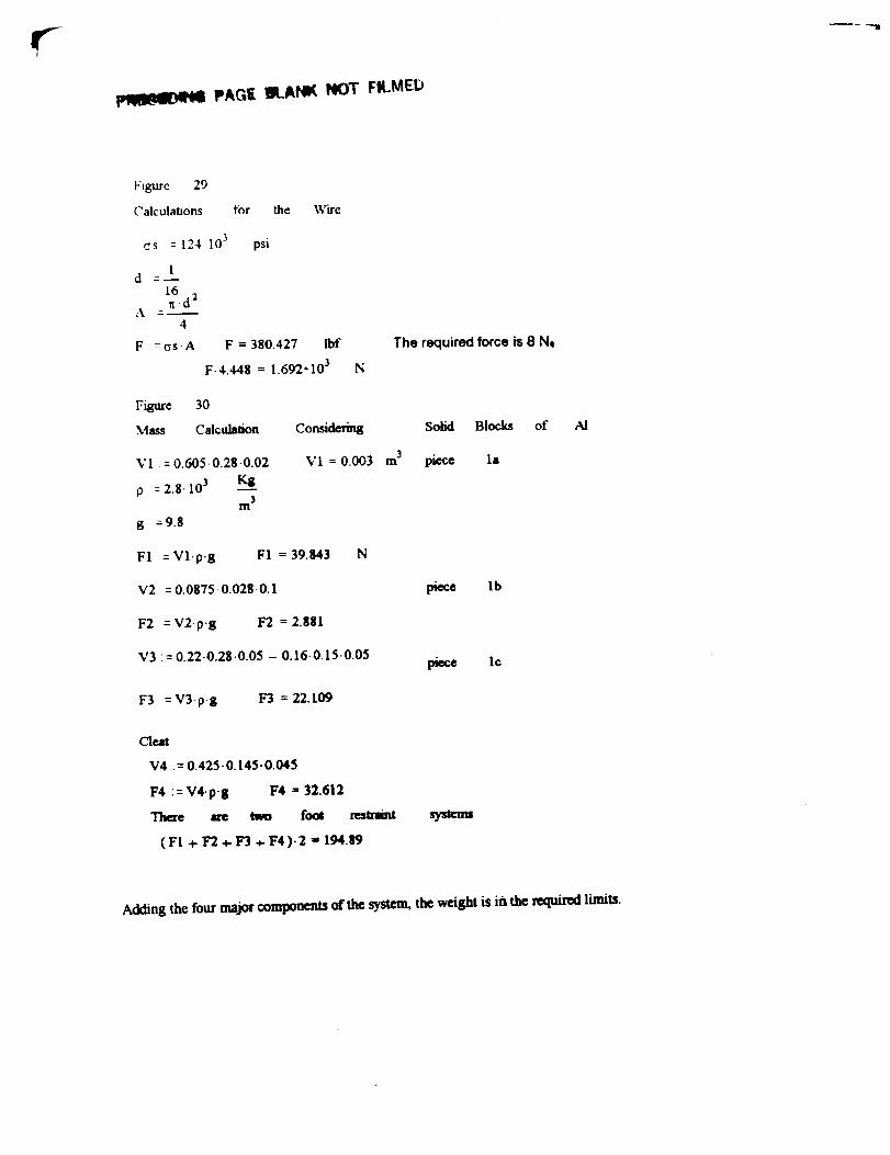
Figurc 29
Calculations for the Wire
cs = 124 103
1d
16.d211A4
F :os.A
psi
F = 380.427 lbf
F- 4.448 --- 1.692-103 N
Figure 30
Mass Calculation Confidcrina
V1 = 0.605-0.28-0.02
p : 2.g. 103 Kg3
m
g :9.8
VI = 0.003
FI :Vl.p.8 FI--39.843 N
V2 -- 0.0875.0.028 0.1
F2 =V2"p'g F2 =2.881
V3 -- 0.22.0.28-0.05 - 0.16-0.15"0.05
F3 =V3-p- 8 F3 = 22.109
m
The required force is 8 NQ
Solid Blocks of
piece la
piece I b
piece tc
AI
Cleat
V4 := 0.425-0.145-0.045
F4 ::V4-p-g F4 = 32.612
There me tw_ foot restraint
(FI + F'2 a,- F3 ÷ F4)-2 I' 194.89
sysmm
Adding the four major components of the system, the weight is iis the required limits.

f_
Appendix C
Specification List

__S__A_66SjRA!
_ D/Wo:ge s
i : D
D
D
DI
i
D
i W
DI
l! DII D!I
D
' D
Ii D
DD
i Di
D
, D
D
"_. W
Figure 31 - Specification List
Specification
For: PortableFoot Restraint
RcquLremcnts
I.
Restrain crew member during EVA tasks.
Allow adjustment offootposition duringEVA task.
2. GeomecvMust conformtoexistingEVA bootgeomeu3,(SeeFigure).
Maximum stowage dimensions: must fit within the shuttlemiddeck modular locker (see Middeck Accommodations
manual in library).
Maximum usagedimensions 91.4 cmx 91.4 cm x 91.4 cm(36"x 36"x36")
Connecttoworksitewithexisdnghex-shapedprobe(SeeFigure"14.3.4.2-I)
3.KinematicsMinimum platformpitch-75 to105".
Minimum platformroll-90to90".
Minimum platformyaw 0 to360".
Constrainpitch,roll,and yaw inadesiredposition.
ResolutionofPitch,roll,and yaw < 15".
Linearbootmodon associatedwithdevice:Lateralstancewidth:0.914m (3fO,Ventral/DoNalstancewidth:0.914m (3f0.Modon within0,914m (36")diametercircle.
4.ForcesMaximum weight of unit 222.4 N (50 lb).
Mt_ widmaml 1334.4 N (300Ib)inany direcdon.
F_mN ofsafety2 1.4
5.Kljusnnems l_-ff'ormcd by a single crew member.
Electrical energy from storage batteries available.
Page 1of2
Rspnsbl Vcrify

Figure 32 - PFR Assembly
I
LockingLocking Pin
PFR Socket /_
Locking _ " I _ _.epoo_ _ ---I- Lo_ P__
[_ ___.___ _ Open Position
- Locking PinLocked Position
OPEN
I I
f
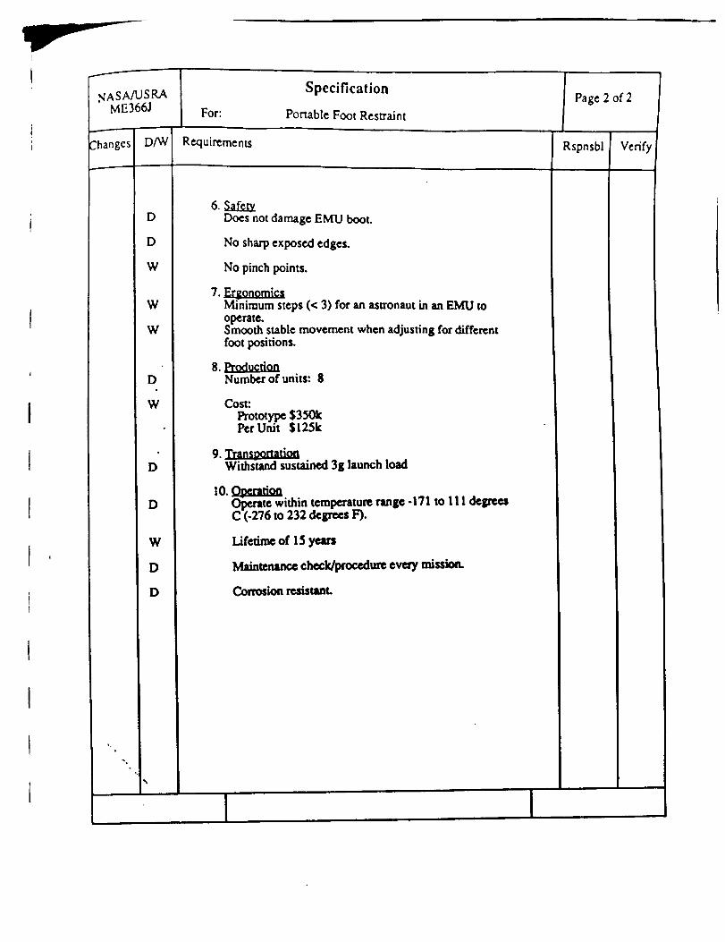
NASA/USRAME366J
2hanges D/W
D
D
W
W
W
D
W
D
D
W
D
D
",i
%
For:
Specification
Portable Foot Restraint
Requirements
Does not damage EMU boot.
No sharpexposed edges.
No pinch points.
, tomm Minimum steps (< 3) for an astronaut in an EMU tooperate.Smooth stable movement when adjusting for differentfoot positions.
Number of units:8
Cost:
Prototype $350kPer Unit $125k
9. :I:m. m aWithstand sustained3g launchload
Operate within temperature range-171 to 111 degreesC (-276 to 232 degrees F).
Lifetime d 15years
Maintcnan_ chock/procodureevery mission.
Corrosion resistant.
Page 2 of 2
Rspnsbl Verify