ME 290-R Spring 2013 McMains Homework # 1 Due Friday Feb 15
6
ME 290-R Spring 2013 McMains Homework # 1 Due Friday Feb 15 5pm (slide under my office door; I will be at an all-day faculty retreat) 1) Obtain access to SolidWorks, for example in the CAD labs in 2105/2107 Etcheverry (currently only open 8am- 5pm). If you’ve never used SolidWorks before, look under the Help menu, SolidWorks tutorials, and complete the first tutorial (“Lesson 1 - Parts” and the tutorial on Revolves and Sweeps. 2) a) Download the SolidWorks part FlipSideToCutDemo.SLDPRT from the class website. Open the part and look at how it was made – expand the three features in the FeatureManager design tree on the left side of the screen by clicking on their ”+” icons, drag your mouse slowly down across the features and their sketches to see the sketches used for each get hightlighted, right-click on the features and select the “Edit Feature” icon (to left of popup icon menu) to see how they were defined, etc. Once you understand how the part was built, try making this modification: Right click on the 2nd feature, “Cut-Extrude2,” select the “Edit Feature” icon, and check the box next to “Flip side to cut.” Accept the change by hitting Enter or clicking the green check button. What happens and why? (Note that Cut-Extrude3 was also defined in the same manner but has different qualitative behavior – why is it different?) b) Based on your (admittedly perhaps limited) experience as a SolidWorks user, what guesses can you reasonably make about the solid modeling representation scheme(s) it might use? How do you think its architecture compares to the advanced architecture model proposed in Requicha’s figure 17? How much of the domain of r-sets does it appear to cover? Come up with at least one example of a solid that you would think could be made using the extrude, rotate, and/or sweep operations you have learned in the tutorials but that nonetheless cannot be built using SolidWorks. Why do you think SolidWorks might not support the geometry you have described? 3) In this problem, you will compare three b-reps: the simple triangulated b-rep scheme described in Requicha section 2.7, the winged edge data structure as summarized in the textbook by Foley, van Dam, et al. section 12.5.2 (see attached scan), and the radial edge structure described in Weiler. Assume a right-handed coordinate system throughout (i.e. faces are oriented counter-clockwise when viewed from the exterior of the solid). v1 v2 v3 v4 e1 e2 e3 e4 e5 f1 f4 e6 f3 f2 Figure 1: A tetrahedron with ID labels for its vertices, edges, and faces. a) Draw diagrams showing in detail how the solid tetrahedron pictured in Figure 1 would be represented using each of the three data structures. Use the ID labels indicated in the figure to identify the faces, edges, and vertices of the tetrahedron. For ID labels for the face-uses, edge-uses, and vertex-uses, please use the referenced entity’s ID number with a subscript, e.g. call edge e4’s two edge-uses eu4 1 and eu4 2 . Show and label all pointers between entities (if drawing where each pointer points clutters the diagram, just give the ID label of where each labeled pointer points). Show all linked lists required. If the specification in the reading is ambiguous, state your assumptions. 1
Transcript of ME 290-R Spring 2013 McMains Homework # 1 Due Friday Feb 15

ME 290-R Spring 2013 McMainsHomework # 1Due Friday Feb 15 5pm (slide under my office door; I will be at an all-day faculty retreat)
1) Obtain access to SolidWorks, for example in the CAD labs in 2105/2107 Etcheverry (currently only open 8am-5pm). If you’ve never used SolidWorks before, look under the Help menu, SolidWorks tutorials, and complete the firsttutorial (“Lesson 1 - Parts” and the tutorial on Revolves and Sweeps.
2)
a) Download the SolidWorks part FlipSideToCutDemo.SLDPRT from the class website. Open the part and look athow it was made – expand the three features in the FeatureManager design tree on the left side of the screen by clickingon their ”+” icons, drag your mouse slowly down across the features and their sketches to see the sketches used foreach get hightlighted, right-click on the features and select the “Edit Feature” icon (to left of popup icon menu) to seehow they were defined, etc. Once you understand how the part was built, try making this modification: Right click onthe 2nd feature, “Cut-Extrude2,” select the “Edit Feature” icon, and check the box next to “Flip side to cut.” Acceptthe change by hitting Enter or clicking the green check button. What happens and why? (Note that Cut-Extrude3 wasalso defined in the same manner but has different qualitative behavior – why is it different?)
b) Based on your (admittedly perhaps limited) experience as a SolidWorks user, what guesses can you reasonablymake about the solid modeling representation scheme(s) it might use? How do you think its architecture compares tothe advanced architecture model proposed in Requicha’s figure 17? How much of the domain of r-sets does it appearto cover? Come up with at least one example of a solid that you would think could be made using the extrude, rotate,and/or sweep operations you have learned in the tutorials but that nonetheless cannot be built using SolidWorks. Whydo you think SolidWorks might not support the geometry you have described?
3) In this problem, you will compare three b-reps: the simple triangulated b-rep scheme described in Requicha section2.7, the winged edge data structure as summarized in the textbook by Foley, van Dam, et al. section 12.5.2 (seeattached scan), and the radial edge structure described in Weiler. Assume a right-handed coordinate system throughout(i.e. faces are oriented counter-clockwise when viewed from the exterior of the solid).
v1
v2
v3
v4
e1
e2
e3
e4 e5
f1
f4
e6
f3
f2
Figure 1: A tetrahedron with ID labels for its vertices, edges, and faces.
a) Draw diagrams showing in detail how the solid tetrahedron pictured in Figure 1 would be represented using eachof the three data structures. Use the ID labels indicated in the figure to identify the faces, edges, and vertices of thetetrahedron. For ID labels for the face-uses, edge-uses, and vertex-uses, please use the referenced entity’s ID numberwith a subscript, e.g. call edge e4’s two edge-uses eu41 and eu42. Show and label all pointers between entities (ifdrawing where each pointer points clutters the diagram, just give the ID label of where each labeled pointer points).Show all linked lists required. If the specification in the reading is ambiguous, state your assumptions.
1

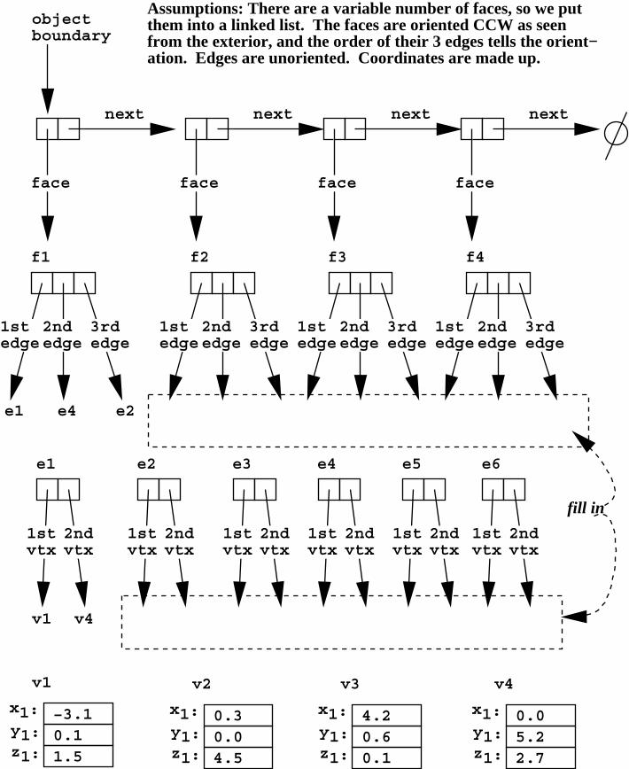
The attached full-page diagram for the Requicha representation has been partially completed for you as an example ofwhat I’m looking for. Complete the missing information in this diagram.
Make a similar diagram for the winged-edge structure, using the same names for pointers as given in the text. Youwill have pointers for the n-vertex, the p-vertex, the n-face, the p-face, the n-face-CW-edge, the n-face-CCW-edge, thep-face-CW-edge, and the p-face-CCW-edge. Please keep them in this same order, for each edge in your diagram.
For the radial edge data structure, it gets very repetitive to show all the details, so it is okay to only show f1 andits associated faces-uses, e1 and its associated edge-uses, and v1 and its associated vertex-uses (just for radial-edge;for winged-edge show all faces, edges, vertices). Put each list in numerical order. Be sure to refer to the Pascaldeclarations in the Weiler paper for complete details; the figures in the paper are somewhat simplified. See me duringoffice hours if you have any questions.
b) Assuming each coordinate and each pointer takes 4 bytes to store, what are the storage requirements for the tetra-hedron in each of the three schemes?
c) For each of the three representation schemes, give an efficient algorithm (using pseudo-code) that takes a pointer toa vertex of a polyhedron as input, and outputs all faces adjacent to it. For the winged-edge scheme, you may assumethat the vertex is on a 2-manifold solid. For the Requicha scheme, you may assume you have a pointer to the top levelof the hierarchy for the entire model. An example of pseudo-code for a related sample HW problem is included at theend of the assignment.
d) For each of your pseudo-code algorithms, how many pointers do you need to follow, worst case, to find the facesadjacent to one of the vertices of the tetrahedron?
2

mcmains
Pencil

mcmains
Pencil
mcmains
Pencil
mcmains
Pencil
next
face
next
face
next
face
next
face
objectboundary
f1
3rdedge
1stedge
2ndedge
f2
3rdedge
1stedge
2ndedge
f3
3rdedge
1stedge
2ndedge
f4
3rdedge
1stedge
2ndedge
e1 e4 e2
e1
v4
1stvtx
2ndvtx
e2
1stvtx
2ndvtx
e3
1stvtx
2ndvtx
e4
1stvtx
2ndvtx
e5
1stvtx
2ndvtx
e6
1stvtx
2ndvtx
x1:y1:z1:
0.11.5
−3.1
v1
x1:y1:z1:
0.04.5
0.3
v2
x1:y1:z1:
0.60.1
4.2
v3
x1:y1:z1:
5.22.7
0.0
v4
v1
Assumptions: There are a variable number of faces, so we put them into a linked list. The faces are oriented CCW as seenfrom the exterior, and the order of their 3 edges tells the orient−ation. Edges are unoriented. Coordinates are made up.
fill in

Date
: ,,''+ 'i
4i::
TCNCCSisiam.org/meetings
'e-& Eobp.r,.,rJ\, Cux .h.a.,t U ?-Nj lary s6"s-x)
4 )t- eA
e\*_ il fq
u-(h -* Fau- ?k a
Society for Industrial and Applied Mathematics3600 University City Science Center Philadelphia, PA 19104-2688
215-382-9800 . Fax 215-386-7999' siam@siam-org' www'siam'org
3 ,"tl"t-z Fa*-Prr * d ,'