
JPEG Compression Indiana University Purdue University Fort Wayne Hongli Luo.

ME 160: Solid ModelingLecture 02: Graphics, Relations, and Revolved Parts
Lecture Instructor Lab Instructor
Jackson Jaworski Omar AlGafri
[email protected] [email protected]
MW | 5:00 – 6:00 p.m. MF: 12:00 – 1:00 p.m.

Overview
• Graphic Language in Engineering
• What Exactly is Solid Modeling
• Using Relations to Reduce Dimensions
• In-Class Group Activity
• Homework

CSG – Example I
P1
P2P1 P2
Basic Shapes Positioned Shapes
𝑃1 ∪ 𝑃2 𝑃1 \ 𝑃2 𝑃2 \ 𝑃1 𝑃1 ∩ 𝑃2

CSG – Example II
\
\
\
\

CSG – Example III
∩
∪\
\

Complexity of Modern Products
• Average car ~30,000 parts• Most parts are from suppliers• All use different materials and
different manufacturing processes
Can an individual engineer or designer deal with all the design tasks?

Communication Languages
• Highly refined, easiest way to communicate an idea. Hard to misinterpret.
• Highly developed system of symbols, allows thoughts and ideas to be passed down. Easy to misinterpret.
• Abstract, based on formal human logic. Requires specific training to interpret.

The Graphic Language in Engineering• In engineering, 92% of the design process is graphically based.
The other 8% is divided among mathematics, written, and verbal communications
92
8
Communication in Engineering
Graphics Verbal, Written, & Math
Which one of those would you rather see?The written text, or graphic?

Functions of Graphic Models
Visualization
• Picture things which do not yet exist.
• Visualize problem solutions and communicate through sketches.
Clarification
• Refine initial sketches to remove ambiguity
• Detailed sketches, 3D computer models, real models
Documentation
• After design solution is finalized, graphics allow for an effective permeant record of the solution

Taxonomy of Modeling MethodsGraphic
ModelingDrafting
Methods
Surface
Modeling
Solid
Modeling Feature Based
Modeling
2D
Modeler
3D
Modeler
Parametric
Surface
Ruled
Surface
Constructive
Boundary
Decomposition

Non-Solid
Solid
Solid vs Non-Solid ModelsA realistic model which encloses a finite and positive amount of space with a well-defined inside/outside.

Cons:
Pros:
Pros. & Cons. Of Solid Modeling
• Uniqueness, realistic, volumetric information• Parametric Design• Automated 2D drawings• Capable of assemblies• Integration with CAD/CAM, VR, CIM, etc…• Dynamic properties: mass, mass center,
moment of inertia, volume, radius of gyration
• More computations then wire-frame• Requires a powerful computer
Number of faces?
Unique?
Realistic?
Physical solid?

Avoid Effort on Unrealistic Product!!!

Boundary Representations (B-rep)
Spatial Decomposition
Constructive Solid Geometry (CSG)
Complexity of Computer Algorithms
Complex shape made up of Boolean operations
Surface data of solid composed of vertices, edges, faces, or equations of splines.
Voxel or octree representation (Volume Pixel)Popular choice for video game graphics

Relations – Smart Dimensions• Dimensions imply a hard constraint on a feature

Relations
Vertical:
Relations can be applied to a single entity
Or to multiple entities
Horizontal: Fixed:
Perpendicular: Parallel: Equal:
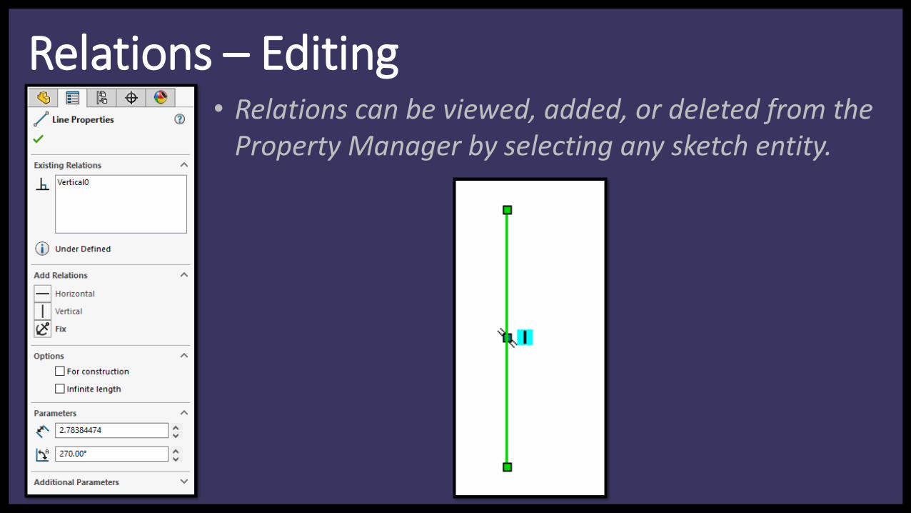
Relations – Editing• Relations can be viewed, added, or deleted from the
Property Manager by selecting any sketch entity.

Relations – Adding• Select multiple entities by holding Ctrl and clicking
lines. Use the Property Manager to add relations.

Relations – View• Click View menu• Activate Sketch Relations
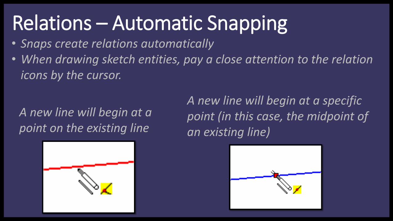
Relations – Automatic Snapping• Snaps create relations automatically• When drawing sketch entities, pay a close attention to the relation
icons by the cursor.
A new line will begin at a point on the existing line
A new line will begin at a specific point (in this case, the midpoint of an existing line)

Relations – Automatic Snapping (cont.)A new line will be perpendicular to an existing line
A new line will be collinear with an existing line
New line will end on an existing circle and be tangent to the circle

Relation Icons
Tangent
Symmetric
Pierce
Along x (3D Sketch)
Horizontal
Vertical
Parallel
Perpendicular
Coincident
Midpoint
Intersection
Equal
Concentric
Coradial
Fixed
Collinear

Dimensions vs Relations
Advantages of using relations: A minimum number of dimensions required, and symmetry is maintained when
dimensions change.

Group Activity
• Get into groups of 2 or 3 people. Must work in a group, no individuals!
Directions• Select a 3D printed part• Measure the geometry of the part and recreate the model in SolidWorks• Select a material property – use your engineering judgement• Take a screen capture of the 4-view, report the mass, volume, and S.A. on
an engineering memo and answer the following questions
1. What was the groups design intent when modeling the part?2. What was the most difficult part of modeling? What was the easiest?3. Name some other ways you could have modeled your part.

Exercise I
• Create the pulley shown in the figure on the left.
• Follow the proceeding tutorial or on pg.’s 34-44 in the book.
• When completed, raise hand and the instructor will check exercise.
• Once marked off, you are free to leave, ask questions, and/or work on homework.

Exercise I
• Be familiar with the SolidWorks part modeling environment
• Use these features:• Revolved Boss/Base• Revolved Cut• Relation Icons• Diameter Dimensions
• Practice considering Design Intent when planning a model
New Toys!

Exercise I – Step 1
• Draw three rectangles of 2 in, 0.25 in, and 1.5 in wide.
• The diameters are 1.0 in, 1.75 in, 5.0 in, and 7.0 in respectively
• Note that Diameter Dimensions are created by dragging the dimension past the centerline.
Base Geometry
Warning!!!What face should the initial sketch be drawn on???

Which face should be the initial sketch plane
Design Intent
So what view should we create our sketch on to achieve standard design intent?
Standard practice is to have the front view provide the best visualization of the principle
views (front, right, top).
Is this always the case?

Exercise I – Step 1
• Start on the right plane• Draw three rectangles of 2 in,
0.25 in, and 1.5 in wide.• The diameters are 1.0 in, 1.75
in, 5.0 in, and 7.0 in respectively
• Note that Diameter Dimensions are created by dragging the dimension past the centerline.
Base Geometry
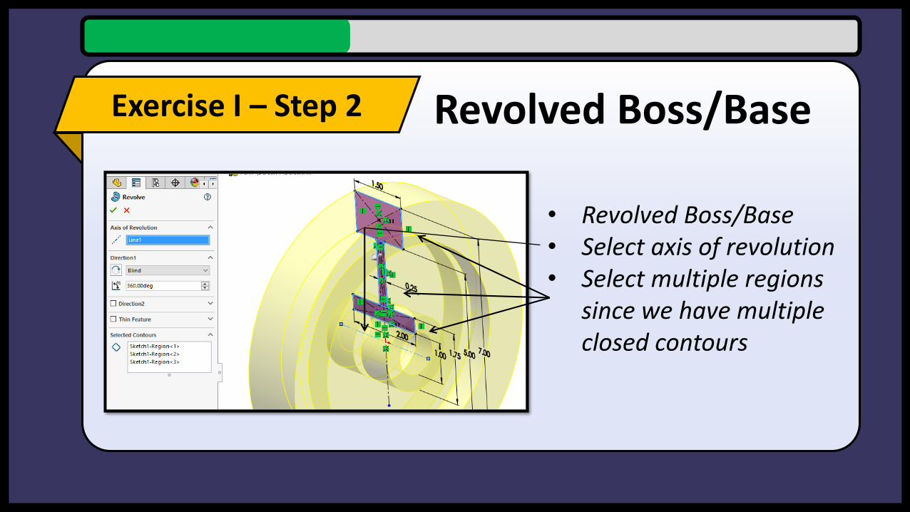
Exercise I – Step 2
• Revolved Boss/Base• Select axis of revolution• Select multiple regions
since we have multiple closed contours
Revolved Boss/Base

Exercise I – Step 3
• Create geometry on right face.
• Use symmetric, coincident, and horizontal relations.
• Make sure to create a horizontal axis with a construction line to revolve the cut around.
Revolved Cut

Exercise I – Step 4
• Create fillets of Ø0.25 on the indicated edges. Rotate the model to select all four edges and complete the fillet operation.
Fillet
Should we have done all four fillet operations together or separately?

Exercise I – Step 5
• Use the Extrude Cut tool to create the keyway
Keyway
Use relations and the given dimensions to
create this!

Design Intent: What is a keyway?
Press Fit
Keyways
Set Screws

Exercise I – Step 6
• Material: Cast Carbon Steel
What is the mass of the part (lbs)?
Material Property
Completed!
Mass: 8.26 lbsVolume: 29.33 in3
S.A.: 151.93 in2

Questions?Homework
Always due a week from when assigned unless told otherwise and due BEFORE the next class.
• Complete HW_02 handout & drawing• Submit drawing on engineering memo• Review the online questions, not due.

Quiz Next Week!
Next week, Tuesday 28
MaterialLecture 1 and Lecture 2
Questions• Multiple choice (~1-2)• Fill in the blank (1)• Simple Solid Model (1)
Time30 Minutes at beginning of class


![[XLS] · Web viewIndiana University-Purdue University Fort Wayne (IPFW) Ramesh Narang 481-6384 narang@ipfw.edu 2101 E. Coliseum Blvd. Fort Wayne 46805 Iowa State University Logistics,](https://static.fdocuments.in/doc/165x107/5b427a187f8b9afa2c8b90e9/xls-web-viewindiana-university-purdue-university-fort-wayne-ipfw-ramesh.jpg)