
mDTM: Multi-Objective Dynamic Thermal …©2014 EDAA mDTM: Multi-Objective Dynamic Thermal...
6
978-3-9815370-2-4/DATE14/©2014 EDAA mDTM: Multi-Objective Dynamic Thermal Management for On-Chip Systems Heba Khdr, Thomas Ebi, Muhammad Shafique, Hussam Amrouch, Jörg Henkel Karlsruhe Institute of Technology (KIT), Chair for Embedded Systems, Karlsruhe, Germany [email protected]; {thomas.ebi, muhammad.shafique, amrouch, henkel} @ kit.edu Abstract— Thermal hot spots and unbalanced temperatures between cores on chip can cause either degradation in performance or may have a severe impact on reliability, or both. In this paper, we propose mDTM, a proactive dynamic thermal management technique for on- chip systems. It employs multi-objective management for migrating tasks in order to both prevent the system from hitting an undesirable thermal threshold and to balance the temperatures between the cores. Our evaluation on the Intel SCC platform shows that mDTM can successfully avoid a given thermal threshold and reduce spatial thermal variation by 22%. Compared to state-of-the-art, our mDTM achieves up to 58% performance gain. Additionally, we deploy an FPGA and IR camera based setup to analyze the effectiveness of our technique. I. INTRODUCTION AND RELATED WORK Shrinking feature sizes of chip structures accompanied with the increase in performance demand result in high on-chip power densi- ties, and thereby high temperatures. Hence, thermal hot spots are induced that jeopardize chip reliability through e.g. electromigration, negative bias temperature instability (NBTI), etc. [12]. Moreover, elevated temperatures decrease interconnects’ speed entailing perfor- mance loss [15]. Two other thermal factors, namely spatial thermal variation (i.e. the temperature difference between two cores Δ i,j T = T core_i – T core_j ) and temporal thermal variation (i.e. temperature difference for a core ΔT in a given time interval due to thermal cycles 1 ), also undermine reliability and reduce the lifetime of the chip [12]. These effects induce uneven interconnect delay throughout the chip dimensions resulting in clock skew problems, and thereby lead to timing errors [8]. Besides their negative impact on reliability, thermal variations akin to unbalanced thermal stress across the chip can cause permanent physical damage through package fatigue and plastic deformation [3]. Relying on cooling infrastructure alone to protect chips from high temperatures is not always feasible, especially for embedded systems, not only because of the relatively high monetary cost [19], but also because of the space the cooling infrastructure requires. As a result, minimizing severe thermal behavior is an important and continuous challenge for researchers in the nano-scale era. A. DTM Challenges For developing efficient dynamic thermal management (DTM) techniques, the following two key challenges need to be addressed: 1) Avoiding Threshold Temperature: The primary goal of most of the DTM techniques is to keep temperatures below the thermal threshold T th , which is a specific temperature that must not be ex- ceeded in order to ensure reliability and maintain performance 2 . Means to accomplish this are, for instance, task migration or Dy- namic Voltage Frequency Scaling (DVFS) when temperatures ap- proach T th . Another related issue is to lower the peak temperature [23, 25] in addition to avoiding the thermal threshold for further improvement of the chip lifetime [26]. 1 Thermal cycles are subsequent periods of heating and cooling. 2 It is used to determine the Thermal Design Power (TDP), i.e., the avg. maximum power of a chip that can be dissipated (e.g., 125W for Intel SCC). 2) Achieving Balancing of Temperatures across the chip to minimize the maximum thermal variation MAX(Δ i,j T), which is the maximum difference in temperature between the hottest and the coldest core. This is typically accomplished by reducing the power consumption on the hottest core through the mechanism of task migration. Achieving balance results in a reduction of the maxi- mum possible temporal thermal variation and balanced aging of different cores in an on-chip system. By decreasing MAX(Δ i,j T), the bounds for ΔT are reduced as well, as migrating a task from the hottest core to the coldest will decrease MAX i,j (T) and increase MIN i,j (T). B. State-of-the-Art DTM Techniques In response to these challenges, several DTM techniques have emerged to address the thermal concerns. Early DTM techniques employ clock gating to prevent the system from hitting a given thermal threshold [7, 18]. Besides preventing to exceed the thermal threshold, these techniques also significantly reduce the power consumption. However, they induce a sharply varying thermal profile, i.e. the temperature observation shows large spatial and temporal variations. Other techniques employ DVFS as a way to provide a smoother thermal control for avoiding a specific thermal threshold [22, 21, 14]. Zanini et al. [21] present a policy based on Model Predictive Control (MPC) to determine the frequency and voltage values, which prevent hitting a given thermal threshold while meeting performance requirements. In order to mitigate the overhead of thermal management that increases as the number of cores on chip grows, a distributed MPC-based technique is introduced in [6]. In [14], distributed PI controllers are employed to adjust the core fre- quencies such that the temperature is kept just below a preset thermal threshold. In order to alleviate the performance penalty associated with the clock gating and DVFS, task migration based techniques are utilized for DTM [11, 20]. Predictive thermal management technique proposed in [20] maintains the system below a specific thermal threshold using task migration. When the temperature of a core exceeds the given thermal threshold, the running task will be migrated to the coolest core. This work exploits the application thermal behav- ior and the core thermal characteristic to predict the temperature. However, these state-of-the-art DTM techniques avoid a thermal threshold but without aiming to balance the temperatures between cores. Moreover, [7, 18] even increase the spatial and temporal thermal variations, especially when applied to systems with many cores. A different branch of DTM techniques focus on balancing tempera- tures between cores to minimize negative effects from thermal variations [13, 17, 9, 10]. Coskun et al. [9] present the concept of a proactive DTM technique that aims to predict temperatures in order to act before thermal problems actually occur. Using an “auto-regressive moving average” model to predict temperatures, they succeed to reduce thermal variation and thermal hot spots. Another work in [10] proposes a distributed thermal management policy DTB-M to balance the temperatures via task migration among only the neighboring cores, so that the performance overhead of task migration is alleviated. Similar to [9], the temperatures of the cores are balanced and the violations of thermal hot spots are reduced but not avoided. Thus,
Transcript of mDTM: Multi-Objective Dynamic Thermal …©2014 EDAA mDTM: Multi-Objective Dynamic Thermal...
978-3-9815370-2-4/DATE14/©2014 EDAA
mDTM: Multi-Objective Dynamic Thermal Management for On-Chip Systems
Heba Khdr, Thomas Ebi, Muhammad Shafique, Hussam Amrouch, Jörg Henkel
Karlsruhe Institute of Technology (KIT), Chair for Embedded Systems, Karlsruhe, Germany
[email protected]; {thomas.ebi, muhammad.shafique, amrouch, henkel} @ kit.edu
Abstract— Thermal hot spots and unbalanced temperatures between
cores on chip can cause either degradation in performance or may
have a severe impact on reliability, or both. In this paper, we propose mDTM, a proactive dynamic thermal management technique for on-
chip systems. It employs multi-objective management for migrating
tasks in order to both prevent the system from hitting an undesirable
thermal threshold and to balance the temperatures between the cores. Our evaluation on the Intel SCC platform shows that mDTM can
successfully avoid a given thermal threshold and reduce spatial
thermal variation by 22%. Compared to state-of-the-art, our mDTM achieves up to 58% performance gain. Additionally, we deploy an
FPGA and IR camera based setup to analyze the effectiveness of our
technique.
I. INTRODUCTION AND RELATED WORK Shrinking feature sizes of chip structures accompanied with the
increase in performance demand result in high on-chip power densi-
ties, and thereby high temperatures. Hence, thermal hot spots are
induced that jeopardize chip reliability through e.g. electromigration,
negative bias temperature instability (NBTI), etc. [12]. Moreover,
elevated temperatures decrease interconnects’ speed entailing perfor-
mance loss [15]. Two other thermal factors, namely spatial thermal
variation (i.e. the temperature difference between two cores Δi,jT =
Tcore_i – Tcore_j) and temporal thermal variation (i.e. temperature
difference for a core ΔT in a given time interval due to thermal
cycles1), also undermine reliability and reduce the lifetime of the chip
[12]. These effects induce uneven interconnect delay throughout the
chip dimensions resulting in clock skew problems, and thereby lead to
timing errors [8]. Besides their negative impact on reliability, thermal
variations akin to unbalanced thermal stress across the chip can cause
permanent physical damage through package fatigue and plastic
deformation [3].
Relying on cooling infrastructure alone to protect chips from high
temperatures is not always feasible, especially for embedded systems,
not only because of the relatively high monetary cost [19], but also
because of the space the cooling infrastructure requires. As a result,
minimizing severe thermal behavior is an important and continuous
challenge for researchers in the nano-scale era.
A. DTM Challenges For developing efficient dynamic thermal management (DTM)
techniques, the following two key challenges need to be addressed:
1) Avoiding Threshold Temperature: The primary goal of most of
the DTM techniques is to keep temperatures below the thermal
threshold Tth, which is a specific temperature that must not be ex-
ceeded in order to ensure reliability and maintain performance2.
Means to accomplish this are, for instance, task migration or Dy-
namic Voltage Frequency Scaling (DVFS) when temperatures ap-
proach Tth. Another related issue is to lower the peak temperature
[23, 25] in addition to avoiding the thermal threshold for further improvement of the chip lifetime [26].
1 Thermal cycles are subsequent periods of heating and cooling.
2 It is used to determine the Thermal Design Power (TDP), i.e., the avg.
maximum power of a chip that can be dissipated (e.g., 125W for Intel SCC).
2) Achieving Balancing of Temperatures across the chip to
minimize the maximum thermal variation MAX(Δi,jT), which is the
maximum difference in temperature between the hottest and the
coldest core. This is typically accomplished by reducing the power
consumption on the hottest core through the mechanism of task
migration. Achieving balance results in a reduction of the maxi-
mum possible temporal thermal variation and balanced aging of
different cores in an on-chip system. By decreasing MAX(Δi,jT),
the bounds for ΔT are reduced as well, as migrating a task from
the hottest core to the coldest will decrease MAXi,j(T) and increase
MINi,j(T).
B. State-of-the-Art DTM Techniques In response to these challenges, several DTM techniques have
emerged to address the thermal concerns. Early DTM techniques
employ clock gating to prevent the system from hitting a given
thermal threshold [7, 18]. Besides preventing to exceed the thermal
threshold, these techniques also significantly reduce the power
consumption. However, they induce a sharply varying thermal profile,
i.e. the temperature observation shows large spatial and temporal
variations. Other techniques employ DVFS as a way to provide a
smoother thermal control for avoiding a specific thermal threshold
[22, 21, 14]. Zanini et al. [21] present a policy based on Model
Predictive Control (MPC) to determine the frequency and voltage
values, which prevent hitting a given thermal threshold while meeting
performance requirements. In order to mitigate the overhead of
thermal management that increases as the number of cores on chip
grows, a distributed MPC-based technique is introduced in [6]. In
[14], distributed PI controllers are employed to adjust the core fre-
quencies such that the temperature is kept just below a preset thermal
threshold. In order to alleviate the performance penalty associated
with the clock gating and DVFS, task migration based techniques are
utilized for DTM [11, 20]. Predictive thermal management technique
proposed in [20] maintains the system below a specific thermal
threshold using task migration. When the temperature of a core
exceeds the given thermal threshold, the running task will be migrated
to the coolest core. This work exploits the application thermal behav-
ior and the core thermal characteristic to predict the temperature.
However, these state-of-the-art DTM techniques avoid a thermal
threshold but without aiming to balance the temperatures between
cores. Moreover, [7, 18] even increase the spatial and temporal
thermal variations, especially when applied to systems with many
cores.
A different branch of DTM techniques focus on balancing tempera-
tures between cores to minimize negative effects from thermal
variations [13, 17, 9, 10]. Coskun et al. [9] present the concept of a
proactive DTM technique that aims to predict temperatures in order to
act before thermal problems actually occur. Using an “auto-regressive
moving average” model to predict temperatures, they succeed to
reduce thermal variation and thermal hot spots. Another work in [10]
proposes a distributed thermal management policy DTB-M to balance
the temperatures via task migration among only the neighboring cores,
so that the performance overhead of task migration is alleviated.
Similar to [9], the temperatures of the cores are balanced and the
violations of thermal hot spots are reduced but not avoided. Thus,

these techniques may not be efficient in terms of thermal threshold
avoidance.
In summary: State-of-the-art DTM techniques either avoid thermal
thresholds or balance temperatures between cores. However, address-
ing only one of these two thermal concerns isolated from the other
(like, only avoiding thresholds) does not solve the other concern (in
this example: thermal imbalance) and thereby is not sufficient to
present a solution for the reliability concerns resulted from the thermal
issues. To illustrate such scenarios, we performed a practical case
study on the Intel SCC platform as discussed below.
C. Motivational Case Study Within this case study, we show how single-objective DTM tech-
niques that aim to either avoid the threshold or balance the tempera-
ture can not address the complete thermal concerns. For this purpose,
we detail two scenarios on the SCC showing 32 core temperatures
while running various workloads. The upper part of Fig. 1 shows an
excerpt of core temperatures of an important observation point. The
temperatures in the first scenario are managed using the threshold-
avoidance DTM [20] (Fig. 1-a), while Balancing DTM is applied on
the second scenario [9] (Fig. 1-b). The lower part of Fig. 1 shows the
maximum spatial variation and temperature over time.
Fig. 1-a shows that the thermal threshold is avoided but the spatial
variations are significantly high, because threshold-avoidance DTM
just considers cores which are approaching the threshold in order to
avoid it using task migration without observing the spatial variation
between the cores to balance them. In contrast, the spatial thermal
variations are reduced in Fig. 1-b, but the preset threshold is hit after a
period of time, because the Balancing DTM just observes the spatial
variation between the cores to distribute them as evenly as possible,
and ignores the case where the temperatures of all cores are increased
and hit the threshold.
34
36
38
40
42
44
0 10 20 30 40
a) b)
Tth = 42 C
b) Balancing DTM [9]a)Threshold-Avoidance DTM [20]M
AX(Δ
i,j T)Tem
pera
ture
[ C
]M
AX
(Δi,jT
)
a) 37% MAX(Δi,jT)
more than b)
Tem
pera
ture
[ C
]
b) 50%Tth
violations
Time [s] Time [s]
Tth
0
5
10
0 10 20 30 40
a) b)
Fig. 1: Motivational case study illustrating the limitations of threshold-
avoidance DTM and Balancing DTM
In order to alleviate the reliability threats incurred from thermal
behavior in on-chip systems, it is necessary to simultaneously
address both thermal concerns (i.e. threshold avoidance and thermal
balancing) in DTM techniques.
D. Our Novel Contributions and Concept Overview We propose a multi-objective thermal management technique
(mDTM) for on-chip systems to jointly avoid thermal thresholds and
thermal imbalance. It employs a two distributed predictor systems (i.e.
two prediction units per core) coupled with two integrated centralized
management units in order to prevent any given thermal threshold and
to minimize thermal variations across the chip, respectively, in a
coordinated fashion. The two centralized management units are
responsible for taking decisions on task migration between the cores
depending upon the output of corresponding predictors.
Evaluation of our technique is performed on a real platform,
namely the Intel Single-Chip Cloud Computer (SCC) [4]. We also
apply our technique to an FPGA-based platform to cover high peak
temperature scenarios that are not possible on the Intel SCC. In the
FPGA setup, we verify the effectiveness of our mDTM technique
using real temperature measurements obtained from an infrared
camera that captures the chip thermal emission.
In our work we target thermal management of cores in an on-chip
system as a multi-objective optimization, i.e. jointly avoiding thermal
threshold and balancing the temperatures in an integrated management
loop.
II. OUR MULTI-OBJECTIVE DYNAMIC THERMAL MANAGEMENT To fulfill the above-discussed goals, our mDTM employs two dis-
tributed predictor systems coupled with two integrated centralized
management units in order to avoid thermal threshold and thermal
imbalance. Each core is equipped with two predictors that obtain the
current temperatures of the cores from their respective thermal
sensors. The first predictor is Avoiding Threshold Distributed Predic-
tor (ATP). It predicts the temperature for each core based on extrapo-
lation from the current temperature, history of previous temperatures,
and increasing or decreasing trend of the core's temperature. This
predicted temperature is used by the Central Management Unit for
Avoiding Threshold (CU-AT) that makes the required decisions of task
migration between the cores in order to avoid the thermal threshold.
The second predictor is Achieving Thermal Balance Distributed
Predictor (ABP). It predicts the temperature deviation for each core
from the average temperature of all cores considering also the current
deviation, history of previous deviations, and increasing or decreasing
trend of the core's deviation. This predicted deviation is used by the
Central Management Unit for Achieving Thermal Balance (CU-AB)
that takes suitable task migration decisions to achieve a thermal
balance between the cores.
Our mDTM achieves proactive thermal management in two ways:
By considering both the thermal history as well as the trend in
temperature change in both predictors, these are able to act be-
fore a temperature threshold is hit.
By aiming to balance temperatures before a given threshold is
hit, isolated temperature peaks are avoided.
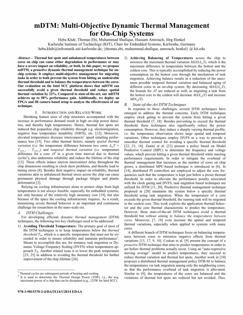
The functionality flow of our mDTM with integrated management
units is demonstrated in Fig. 2. In the following, we explain the four
key functional blocks of our mDTM followed by the coordinated
operation of two management units in Section II.A.
1) Avoiding Threshold Distributed Predictor System (ATP): It
predicts – for each core – the temperature for the next quantum
through extrapolation (RAT; Eq.1) using the temperature Tk at the
current point of time k and the history of previous temperature profile.
k 1
AT ,k k i
i k n
R T T n H (1)
Note that Tk is a measured value of core temperature at runtime.
Therefore, the thermal effects from the surrounding cores are implicit-
ly involved in Tk.
The term
k 1
i
i k n
T n denotes the average temperature over a speci-
fied time window to consider only the recent thermal history. Consid-
ering the whole thermal history results in inaccuracy in the prediction
when a dynamic workload is applied; which is the more general case
in the real systems. Therefore, for all predictors, we define a time
window Wn: [tk-n, tk-1], where tk-1 is the last instant of time before the
current point of time tk. This window limits the history to the recent
thermal history of the core of length n. The parameter H in Eq.1 is a
temperature offset used to determine whether the average temperature
of the history is high or low. If the average of history is greater than
H, the RAT value is increased, but if it is lower than H, the RAT value is
decreased, giving preference to cores that have been colder in the past.
In order to incorporate the rate of increase or decrease in the tem-
perature for two consecutive time quantum, our predictor employs a
correction factor to RAT, as shown in Eq.2, where Tk-1 denotes the
temperature in previous point in time k-1 and θ is the constant to
control the strength of correction.
AT ,k AT ,k k k 1R R T T (2)
2) Central Management Unit for Avoiding Threshold (CU-AT): Based on the RAT values of all cores, CU-AT determines, from which
cores, tasks should be migrated and to which cores tasks can be
assigned. For that purpose, two values are defined: the Proactive
Threshold (ProTth) and the Availability (A). When RAT of a given core
reaches the ProTth, CU-AT migrates a task from that core (see Eq.3).
In contrast, when RAT of a given core is equal to or less than the
Availability value, CU-AT can assign tasks to this core (see Eq.4).
AT thR ProT (3)
ATR A (4)
Intuitively, the relation between the predefined threshold Tth,
ProTth and A is given as follows:
th thT ProT A (5)
3) Achieving Thermal Balance Distributed Predictor System
(ABP): Unlike the ATPs that considers the actual temperature, the
ABPs considers the error difference between the actual temperature Tk
and the chip average temperature Tavg(k) to compute the difference (ek)
of a core’s current temperature from the average temperature. Howev-
er, the extrapolation models of ABP are similar to that of ATP, i.e.
ABP also considers the history and correction factor, but in terms of
the error term; see Eqs.6 and 7.
k 1
AB,k k i k k avg
i k n
R e e n ; where e T T (6)
AB,k AB,k k k 1R R e e (7)
4) Central Management Unit for Achieving Thermal Balance
(CU-AB): For CU-AB, the unit responsible for achieving balance, we
define a balancing parameter Bal. It represents the temperature above
Tavg that requires task migration to achieve thermal balance within a
specific range in order to consider the performance overhead induced
from task migration processes. The lower Bal is, the more migrating
processes occur and the more performance overhead is incurred, but
the less spatial variation and vice versa. Additionally, the ratio
between the total number of tasks M that are running on the given on-
chip system and the number of cores N also play a role in the decision
of CU-AB, because having more tasks than cores provides more
opportunity to achieve thermal balance between the cores. Therefore,
we define a run-time parameter, called DyBal, which is dynamically
re-adapted if M changes allowing more task migrations when dealing
with several tasks; see Eq.8.
DyBal Bal N / M (8)
Thus, CU-AB decides to migrate a task from a given core when
the output of the relevant ABP RAB obtained from Eq.7 meets the
following condition (Eq.9).
ABR DyBal (9)
A. Integrated Management in mDTM Since avoiding the thermal threshold is more critical than achiev-
ing balance, the ATPs have a higher priority over the ABPs and,
hence, the ATPs are activated first. After the ATPs perform the
required predictions, their outputs are passed to the CU-AT which
migrates tasks from cores that meet the migrating condition given in
Eq.3 and places these tasks in a waiting queue. Then, the CU-AT
identifies which cores can run these waiting tasks through checking
the availability condition (Eq.4). If there is no migration command
issued by the CU-AT in the current iteration and no tasks occupy the
waiting queue, the ABPs will be activated. Otherwise, they remain
inactive in this iteration to avoid unnecessary task migrations, as the
core temperatures will change after applying the task migrations
issued by the CU-AT.
Once the ABPs are activated, they calculate RAB values to be
passed to the CU-AB. Then, CU-AB migrates tasks from the core
which has the highest value of RAB and meets the Eq.9, and assigns
this task to the core with the lowest value of RAB. While CU-AT and
CU-AB may choose different tasks to migrate, a task chosen by the
CU-AT will always be migrated from a hotter core to a colder one,
thus never contradicting the CU-AB. The ABPs remains deactivated
until all tasks in the waiting queue are assigned to available cores, to
ensure these tasks are executed. Fig. 2 illustrates the coordinated
operations of CU-AT and CU-AB management units.
The migration commands issued by CU-AB or CU-AT during
each iteration of the management loop are sent to the cores. We have
adapted the OS scheduler on each core to receive commands to start
and/or stop tasks. In order to get faster cooling down, besides task
migration, we use DFS knob to scale down the frequency of the core
to the minimum possible frequency when a task is migrated from it.
However, when a task is assigned to a core, we scale the frequency up
to the maximum value to obtain better performance. After applying
the decisions on all cores, the management loop returns to the first
step. This loop is repeated for each discrete management interval dt.
Central decision Unit for
Achieving Thermal Balancing
(CU-AB)
AT- Predictors
Stop a task
from Core i
& put it in the
Waiting queue
Assign a task
from the waiting
queue to core i
and start it
Enable ABPs
& get the average of
chip temperature Tavg
Stop a task
from the
core c
Assign the
Stopped task
to the core of
lowest RAB value
Waiting Queue
(WQ)
No
commands from
CU-AT& WQ
empty
…
ATP1
T1
RAT1
Central decision Unit for
Avoiding Threshold Temperature
(CU-AT)
RAT,i >=
ProTth
RAT,i < A
True TrueTrue
AB- Predictors
RAB>=
DyBal
Find the core c
of the highest
RAB value
Get the core temperatures
Send the issued commands to
the corresponding core dispatchers
True
False
Core 1
Dispatcher s
NoC
Multi-Core System
Core 2
Dispatcher s
Core N
Dispatcher s
…
…T1 T2 TN
task
task
task
…ATP2
T2
RAT2
ATPN
TN
RATN
ABP1
T1, Tavg
RAT1
…ABP2
T2 , Tavg
RAT2
ABPN
TN , Tavg
RATN
s denotes the sensor
Fig. 2: Overview and operational flow of our mDTM
Discussion: By adjusting the parameters for our management
modules to the physical properties of the chip, we can guarantee that a
threshold cannot be hit given the current thermal state and the history.
While this results in more false positives (i.e. predicting a threshold
hit too early, or when none would occur) it eliminates more critical
false negatives. In our experiments, we find the rate of false positives
to be at most 1 per workload configuration (i.e. number and type of
tasks), mainly due to the self similarity of sequential thermal cycles.
B. mDTM’s Effect on Thermal Cycling An increase in thermal cycling could be the direct result of ther-
mal management techniques such as mDTM which migrates tasks
from the hot cores and assign tasks to them after they cool down
within a period of time. The negative effect of thermal cycling on the
lifetime of chip is determined by two factors: the difference between
the max and min temperature within the cycle ΔT, as well as the total
number of cycles during the lifetime of the chip Ƞcy [12].
Since ATP considers the thermal history of the cores, CU-AT re-
duces the number of thermal cycles. When the thermal history in Wn is
relatively hot, the RAT is increased, decreasing the ability of the given
core to run tasks (see the availability condition Eq.3). The length of
Wn influences the rate of reducing Ƞcy; the longer Wn the less Ƞcy. To
reduce ΔT within thermal cycles, we can decrease the difference
between the Proactive Threshold (ProTth) and the Availability (A), by
increasing the value of A. Furthermore, ΔT can be reduced also
through minimizing the parameter Bal. However, minimizing ΔT will
increase task migration rate resulting in more performance overhead.
Although reducing ΔT in our technique increases Ƞcy, but the
number of cycles for different ΔT is not comparable unless they are
normalized to a reference temperature change.
III. EVALUATION AND EXPERIMENTAL RESULTS We evaluate our mDTM on the Intel SCC platform with 48 full IA
P54C cores and 48 thermal sensors to measure the core temperatures.
However, the peak temperature that the SCC cores reach does not
exceed 45°C in our experiments due to the cooling system attached to
the SCC chip. Therefore, for evaluation of our technique on the real
system, we adopt a low value for the thermal threshold, i.e. 42°C in
our experiments on the SCC platform. Additionally, to illustrate the
effectiveness of our mDTM in avoiding high thermal thresholds, we
deployed an FPGA-based setup where higher peak temperatures can
be incurred; i.e. 85°C. In this case, we set the threshold to 76°C. Our
FPGA setup emulates four cores as rectangular regions of Toggle-Flip
Flops (T-FFs) and the task as the action of toggling the FFs on a
Xilinx Virtex5 FPGA [5]. For temperature measurement of the FPGA,
we use an infrared thermal camera DIAS pyroview 380L compact [2]
that is capable of capturing temperatures of structures with a spatial
resolution of 50 µm per pixel and an accuracy of ±1°C [2].
A. Evaluation on Intel SCC Platform We implement our mDTM technique in the OS scheduler. The
predictors ATPs and ABPs are distributed on the cores while CU-AT
and CU-AB are realized to one central core. For rapid evaluation,
however, we find it beneficial to run our technique on a PC connected
to the SCC in order to allow rapid testing of different configurations
and also extracting and processing large log traces for analyzing the
results of our technique.
We set the management step dt, which is the minimum possible
period in the off-chip scenario. However, it is still 5x less than the
state-of-the-art technique [14], and thus, our technique can react at a
fine granularity.
The parameter ProTth is given as: ProTth = Tth - maxΔT, where
maxΔT is the maximum temperature increment of the SCC, during dt.
Empirically, we find that maxΔT is equal to 2.5. Considering the
potential noise in the sensors measurements, we set ProTth to 39.
Observing the incurred increase in temperature, when a task is migrat-
ed to a core, we set A to 33, which avoids the need to re-migrate the
task again from the current core. The rest of the parameters are set
empirically. Table I contains the parameter values used by the man-
agement modules.
TABLE I PREDICTOR PARAMETER SETTINGS
Parameter θ ProTth A H n
Value 0.5 39 33 38 10
We execute various scenarios with different number of tasks and
cores. We test both benchmarks burnP5 and cpuburn-in from the
benchmark suite cpuburn [1], but we find that burnP5 exhibits the
most heat generation of a task on the SCC due to its significant stress
on the targeted cores, therefore we employ it in the most of our
experiments on the SCC.
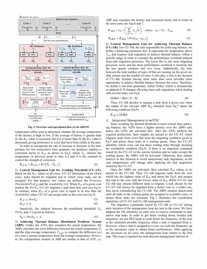
The results of six experiments are demonstrated in Fig. 3 as quar-
tiles of 32 core temperatures during runtime, depicted in a representa-
tive window of the execution time to keep the results comprehensible.
At the beginning of these experiments, we run 16 tasks (burnP5) on
16 cores, and let the other 16 cores idle to be exploited later through
task migration. However, our implementation is not limited to this
scenario and in the next section other scenarios are demonstrated
when the number of the tasks and cores are identical. Fig. 3-b illus-
trates the core temperatures when our mDTM technique is applied.
Once the tasks start on the cores, the temperatures begin to increase on
the running cores. As long as the temperature is still relatively far
from the threshold (42°C), the CU-AT does not migrate any task, thus
ABPs are activated and CU-AB triggers task migration between cores
in order to balance the temperature. When the temperature approaches
the predefined threshold on some cores, the CU-AT stops the tasks
from these cores and places them temporarily in the waiting queue
until another core can run the stopped tasks (see Eq.4). As noted in
Fig. 3-b, our mDTM technique is capable of preventing the threshold
from being hit during runtime, besides reducing the thermal spatial
variation between cores. The mDTM capability to achieve its goal is
illustrated by a comparison with the base-case in Fig. 3-a, which
presents the core temperatures when no thermal management is
applied to the system.
In our experiments, we compare our work with two single-
objective state-of-the-art DTM [9, 20], namely bDTM and pDTM,
respectively. For fairness of comparison between different DTM
policies, we provide same methods for task migration and prediction.
Therefore, the difference purely illustrates the effect of optimization
objective of different DTM policies. From [9], we apply the proposed
balancing policy which redistributes tasks among cores to achieve
thermal balancing. It is obvious from Fig. 3-c, that bDTM balance the
temperatures among the cores. It also reduces the rate of hitting the
threshold in the early phase of the execution time. However, after a
period of time, when the temperatures of all the cores increase, a lot of
cores hit the threshold. In contrast to that, the threshold is avoided
when pDTM [20] is applied (see Fig. 3-d), but the thermal spatial
variation is not reduced. We observe that the maximal spatial thermal
is reduced by 22% when our mDTM is applied (see Fig. 3-b) com-
pared to the results of the pDTM (see Fig. 3-d).
To examine mDTM's capability of adapting to additional sudden
stress applied on the system, we start 16 additional tasks on the
unoccupied cores at the point of time t= 2.4s during runtime (see Fig.
3-e). Fig. 3-f illustrates similar experiment but with different addition-
al tasks (cpuburn-in). It is shown in both Fig. 3-e and Fig. 3-f, that at a
specific point of time the temperatures increase suddenly on all cores.
Nevertheless, our mDTM still avoids the threshold and balances
temperatures.
Overhead: To evaluate the overhead of our technique we examine the
communication and computation required to implement one manage-
ment step. The computation overhead is 0.07% of each management
step (off-chip). On-chip, the computational overhead of the distributed
ATPs and ABPs is 0.086% and the centralized CU-AT and CU-AB is
0.068%. The communication latency is considerably higher in the off-
chip implementation, taking 94 µs and 2.4 µs for off-chip and on-chip,
respectively [16]. From our experiments, at each dt, the maximum
amount of the sent packets is up to 5.7 KB/s at the bottleneck case.
Compared to the total bandwidth of the NoC on the SCC (64 GB/s),
we find that the total communication overhead is less than 0.01% of
the total bandwidth.
B. Analysis on FPGA-based Setup
50
55
60
65
70
75
80
85
90
95
0 6 12 18 24 30 36Time [s]
Te
mp
era
ture
[ C
]
DIAS Pyroview
thermal camera
Xilinx Virtex-5
Without packaging
Threshold
50
55
60
65
70
75
80
85
90
95
0 6 12 18 24 30 36
core1 core2
core3 core4
a) mDTM is
applied
b) No DTM is
applied
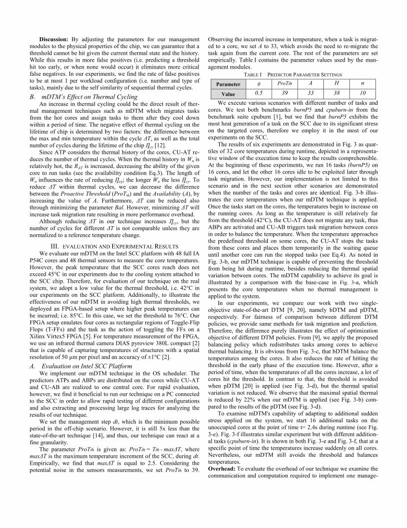
Fig. 4: The thermal behavior on the FPGA setup in two cases:
a) applying our mDTM policy; b) without a DTM policy
In our FPGA setup, we run an experiment with two tasks and de-
pict the temperatures captured by the infrared camera (see Fig. 4).
Fig. 4-a and –b illustrate the temperature profiles over time for two
cases, i.e. with and without our mDTM, respectively. Analogous to
our observation in the SCC experiments, we notice in Fig. 4-a how the
core temperatures increase continuously once the tasks run on the
cores. CU-AB balances the temperature between the cores as long as
no core meets the migrating condition of the CU-AT. When any core
temperature approaches the preset threshold (76°C), CU-AT works to
avoid the threshold. Whenever temperature goes down and diverges
from the threshold, and no tasks occupy the waiting queue the CU-AB
commences operation. As seen in Fig. 4-a, the temperature never
reaches the predefined threshold. Thus, we ensure that our mDTM
technique can avoid high thresholds. However, in Fig. 4-b, where no
thermal management is applied, the temperatures of all cores exceed
the thermal threshold reaching more than 90 °C.
IV. PERFORMANCE COMPARISON TO STATE-OF-THE-ART Since keeping associated performance penalties low is a key con-
cern of DTM techniques, we evaluate our mDTM in terms of perfor-
mance overhead. We compare to D2TM proposed in [14], as it aims to
maximize the performance under thermal constraint. D2TM imple-
ments distributed PI controllers at all cores to adjust core frequencies
to keep the temperatures slightly below the thermal threshold. The
frequency is scaled one level down when a thermal threshold is about
to be hit, and scaled one level up when the core temperature is less
than the thermal threshold with a specific offset. We implement their
PI controller on the cores of the Intel SCC platform.
0
10
20
30
40
50
60
Bett
er
Tim
e [s
]
T denotes Task
C denotes Core
Number of Tasks and Cores
mD
TM
12T@16C 16T@16C 16T@24C 24T@24C 24T@32C 32T@32C
D2T
M
mD
TM
D2T
M
mD
TM
D2T
M
mD
TM
D2T
M
mD
TM
D2T
M
mD
TM
D2T
M
30% 27% 55%
53%58%
52%
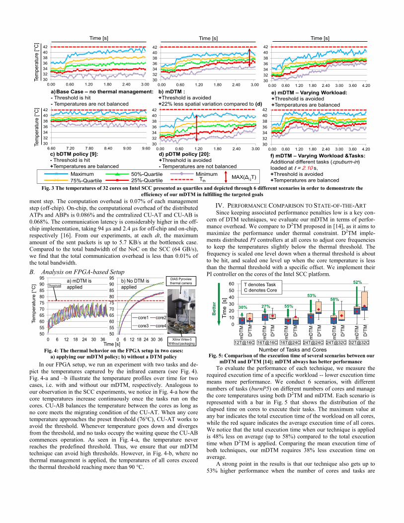
Fig. 5: Comparison of the execution time of several scenarios between our
mDTM and D2TM [14]; mDTM always has better performance
To evaluate the performance of each technique, we measure the
required execution time of a specific workload -- lower execution time
means more performance. We conduct 6 scenarios, with different
numbers of tasks (burnP5) on different numbers of cores and manage
the core temperatures using both D2TM and mDTM. Each scenario is
represented with a bar in Fig. 5 that shows the distribution of the
elapsed time on cores to execute their tasks. The maximum value at
any bar indicates the total execution time of the workload on all cores,
while the red square indicates the average execution time of all cores.
We notice that the total execution time when our technique is applied
is 48% less on average (up to 58%) compared to the total execution
time when D2TM is applied. Comparing the mean execution time of
both techniques, our mDTM requires 38% less execution time on
average.
A strong point in the results is that our technique also gets up to
53% higher performance when the number of cores and tasks are
30
32
34
36
38
40
42
0.00 0.60 1.20 1.80 2.40 3.00
30
32
34
36
38
40
42
0.00 0.60 1.20 1.80 2.40 3.00
30
32
34
36
38
40
42
6.60 7.20 7.80 8.40 9.00 9.60
a)Base Case – no thermal management:
- Threshold is hit
- Temperatures are not balanced
b) mDTM :
+Threshold is avoided
+22% less spatial variation compared to (d)
Tem
pe
ratu
re [ C
]Time [s] Time [s]
30
32
34
36
38
40
42
0.00 0.60 1.20 1.80 2.40 3.00
30
32
34
36
38
40
42
0.00 0.60 1.20 1.80 2.40 3.00 3.60 4.20
Time [s]
c) bDTM policy [9]:
- Threshold is hit
+Temperatures are balanced
d) pDTM policy [20]:
+Threshold is avoided
- Temperatures are not balanced
e) mDTM – Varying Workload:
+Threshold is avoided
+Temperatures are balanced
30
32
34
36
38
40
42
0.00 0.60 1.20 1.80 2.40 3.00 3.60 4.20
f) mDTM – Varying Workload &Tasks:
Additional different tasks (cpuburn-in)
loaded at t = 2.10 s,
+Threshold is avoided
+Temperatures are balanced
Maximum Minimum
75%-Quartile
50%-QuartileTth25%-Quartile
MAX(Δi,jT)
Tem
pe
ratu
re [ C
]
Fig. 3 The temperatures of 32 cores on Intel SCC presented as quartiles and depicted through 6 different scenarios in order to demonstrate the
efficiency of our mDTM in fulfilling the targeted goals

identical. In this case, our mDTM also migrates tasks, because the
incurred temperature of the task is distinct in each core. Despite the
overhead of task migration, our mDTM performance surpasses D2TM
performance.
To present a more detailed picture of the comparison results and
to find an interpretation of the performance gain of mDTM compared
to D2TM, we present the corresponding temperatures and frequencies
on core 13, as an example, in the scenario of 24 tasks running on 24
cores in Fig. 6 and Fig. 7, respectively. From Fig. 6, it is obvious that
the peak temperatures resulted from mDTM are higher than ones
resulted by D2TM, because the cores of our mDTM always run their
tasks with the highest frequency (800 Mhz), and thereby obtain more
performance. In addition, when the core meets the migration condi-
tion, our mDTM stops the tasks from the core and scales down the
frequency to the lowest value (100 Mhz) if possible. That leads to fast
cooling and significant decrease in temperature, and thus when the
core run again a task, it can remain in operation for longer time
periods until its temperature rises again. In contrast to our technique,
D2TM scales frequency down step by step and keeps the task running
in the case of approaching the threshold, and scales it up step by step
in the case of having less temperature. Therefore, there is not enough
period for cooling down in the first case and task execution time
becomes inefficient in the second one. Fig. 7 illustrates the frequency
scaling operations done by both techniques. We notice, when mDTM
is applied, the core finishes its task faster compared to D2TM, result-
ing in better performance.
Time [s]
Tem
pera
ture
[ C
]
32
34
36
38
40
42
0.06 1.86 3.66 5.46 7.26 9.06 10.86 12.66 14.46 16.26
Our ATAB Dist.PID2TM [14]Our mDTM
0.0 1.8 3.6 5.4 7.2 9.0 10.8 12.6 14.4 16.2
Fig. 6: Temperature comparison at one of the core
While the majority of mDTM computation can be executed in
parallel through the distributed ATPs and ABPs, the main limitation
of our technique is that it relies on the central CU-AT and CU-AB to
make decisions based on these computations. This presents a bottle-
neck in the scalability of the technique. However this was not an issue
on the tested 48 core Intel SCC, since the inherent latency of thermal
effects remains lower than the communication time required to
acquire predictor outputs and act upon them. Additionally, our
technique can easily be extended to follow hierarchical structure in
order to be scalable in the emerging manycore systems.
0
200
400
600
800
1000
0 1 2 3 4 5 6 7 8 9 10 11 12 13 14 15 16 17 18
Performance
Gain 18%
Time [s]
Fre
quency [
Mhz]
D2TM [14]Our mDTM
Fig. 7: Frequency scaling comparison at one of the core
V. CONCLUSION In this paper, we proposed a multi-objective thermal management
technique to simultaneously prevent hitting an undesirable threshold
and distributing temperature between cores as uniformly as possible
with low impact on the performance. We illustrate the effectiveness of
our technique using two real-world platforms. Additionally, different
experiments running on Intel SCC showed that our goals are success-
fully accomplished with 22% less spatial thermal variation. Finally,
we achieved 58% better performance results compared to other
competitors. Multi-objective DTM techniques provide a more feasible
and practical solution to effectively avoid thermal concerns in on-chip
systems that undermine their reliable operations and life time.
I. ACKNOWLEDGMENT This work is supported in parts by the German Research Founda-
tion (DFG) as art of the priority program "Dependable Embedded Systems" (SPP 1500 - spp1500.itec.kit.edu).
REFERENCES [1] Cpuburn. http://www.cpuburnin.com/.
[2] DIAS Infrarred Camera. http://www.dias-infrared.com/pdf/-pyroview380lcompact_eng.pdf.
[3] Failure mechanisms and models for semiconductor devices, JEDEC. http://www.jedec.org.
[4] Intel labs. http://www.intel.com/content/www/us/en/research/intel-research.html.
[5] Xilinx fpgas. http://www.xilinx.com.
[6] A. Bartolini, M. Cacciari, A. Tilli, and L. Benini, “Thermal and energy management of high-performance multicores: Distributed and self-calibrating model-predictive controller”, IEEE Transactions on Parallel and Distributed Systems, pages 170–183, 2013.
[7] D. Brooks and M. Martonosi, “Dynamic thermal management for high-performance microprocessor”, HPCA’01, pages 171–182, 2001.
[8] A. Chakraborty, K. Duraisami, A. Sathanur, P. Sithambaram, L. Benini, A. Macii, E. Macii, and M. Poncino, “Dynamic thermal clock skew compensation using tunable delay buffers”, ISLPED’06, pages 162–167, 2006.
[9] A.K. Coskun, T.S. Rosing, and K.C. Gross, “Proactive temperature balancing for low cost thermal management in MPSoCs”, ICCAD’08, pages 250–257, 2008.
[10] Y. Ge, P. Malani, and Q. Qiu, “Distributed task migration for thermal management in many-core systems”, DAC ’10, 2010.
[11] M. Gomaa, M. D. Powell, and T. N. Vijaykumar, ”Heat-and-run: leveraging SMT and CMP to manage power density through the operating system”, ASPLOS’04, pages 260–270, 2004.
[12] J. Henkel, T. Ebi, H. Amrouch, and H. Khdr, “Thermal management for dependable on-chip systems”, ASP-DAC’13, Jan. 2013.
[13] W-L. Hung, Y. Xie, N. Vijaykrishnan, M. Kandemir, and M. J. Irwin, “Thermal-aware task allocation and scheduling for embedded systems”, DATE’05, pages 898–899, 2005.
[14] M. Kadin, S. Reda, and A. Uht, “Central vs. distributed dynamic thermal management for multi-core processors: which one is better?”, GLSVLSI’09, pages 137–140, 2009.
[15] V. Narayanan and Y. Xie, “Reliability concerns in embedded system designs”, Computer, pages 118–120, Jan. 2006.
[16] P. Reble, C. Clauss, M. Riepen, S. Lankes, and T.Bemmerl, “Connecting the cloud: Transparent and flexible communication for a cluster of intel SCCs”, https://communities.intel.com.
[17] S. Sharifi, A.K. Coskun, and T.S. Rosing, “Hybrid dynamic energy and thermal management in heterogeneous embedded multiprocessor SoCs”, DAC’10, pages 873–878, Jan. 2010.
[18] K. Skadron, M.R. Stan, W. Huang, Sivakumar Velusamy, Karthik Sankaranarayanan, and D. Tarjan, “Temperature-aware microarchitecture”, ISCA’03, pages 2–13, Jun. 2003.
[19] Chengmo Yang and A. Orailoglu, “Processor reliability enhancement through compiler-directed register file peak temperature reduction”, DSN’09.pages 468–477, 2009.
[20] Inchoon Yeo, Chih Chun Liu, and Eun Jung Kim, “Predictive dynamic thermal management for multicore systems”, DAC’08, 2008.
[21] F. Zanini, D. Atienza, L. Benini, and G. De Micheli. “Multicore thermal management with model predictive control”, ECCTD, pages 711–714, Aug. 2009.
[22] F. Zanini, D. Atienza, and G. De Micheli, “A control theory approach for thermal balancing of MPSoC”, ASP-DAC '09, pages 37–42, Jan. 2009.
[23] S. Corbetta, W. Fornaciari, D. Zoni, “A Temperature and Reliability Oriented Simulation Framework for Multi-Core Architectures”, ISVLSI’12, pp 51-56, Aug. 2012.
[24] S. Corbetta, W. Fornaciari D. Zoni, “Thermal-Performance Trade-off in Network-On-Chip Architectures”, IEEE SoC 2012, October, 2012.
[25] T.Ebi, H.Amrouch, J.Henkel, “COOL: Control-based Optimization of Load-balancing for Thermal Behavior”, CODES+ISSS’12, 2012.
[26] J. Henkel, L. Bauer, N. Dutt, P. Gupta, S. Nassif, M. Shafique, M. Tahoori, N. Wehn, “Reliable on-chip systems in the nano-era: Lessons learnt and future trends”, ACM/IEEE DAC, 2013.


![Development Objective Agreement and Bilateral Project ... · The Development Objective ("Objective") is: [state objective]. Section 2.2. Results. In order to achieve that Objective,](https://static.fdocuments.in/doc/165x107/5f056b8e7e708231d412dfe2/development-objective-agreement-and-bilateral-project-the-development-objective.jpg)


![AOK,IAA - profilnakupuvacha.com · o6ruecrseHa noplqKa vpe: ny6.ruuuo c6cre3aHlre c flpe,lMer: ,,Ilt6op aa kotc)]J,mdtm 3a ynpalrcHnea*e Ha cmpoumeirea uadtop no 6peve aa CMP cr,etacto](https://static.fdocuments.in/doc/165x107/5c66ccdf09d3f2c14e8c8fb8/aokiaa-o6ruecrseha-noplqka-vpe-ny6ruuuo-c6cre3ahlre-c-flpelmer-ilt6op.jpg)


