MDSRC - 2017 Proceedings, 27-28 December, 2017 …MDSRC - 2017 Proceedings, 27-28 December, 2017...
8
MDSRC - 2017 Proceedings, 27-28 December, 2017 Wah/Pakistan 1 Three Phase Frequency Converter Quratulain Jamil 1 , Hafiz Muhammad Ashraf Hayat 2 , Haris Masood 3 1 Department of Electrical Engineering Wah Engineering College, University of Wah [email protected] 2 Department of Electrical Engineering Wah Engineering College, University of Wah [email protected] 3 Department of Electrical Engineering Wah Engineering College, University of Wah [email protected] ABSTRACT The radar operates at a frequency of 400Hz but the frequency coming from main is 50Hz. So the project is devised to carter this problem. Secondly, the power supply units that are used to convert three- phase AC voltage from 50Hz to 400Hz are too big in size and are difficult to be carried to far-off places. It is designed to carter this drawback and is made compact yet cost effective. The project includes an AC to DC (converter) circuit and then DC to AC (inverter) circuit by switching DC voltage using MOSFETs or IGBT, to achieve 400Hz.The work cycle begins as the 3 phase AC is converted to DC using rectifier circuit and then capacitor is used to smooth the voltage. This DC voltage is then converted into 400Hz by using a 3 phase inverter circuit. The output of 3 different phases is then supplied to the radar. Keywords: IGBT’s, Pulse Generation, Rotary converters, Six-pulse inverter circuit, Three- phase inversion. 1. INTRODUCTION A radar operation requires an input of 3 phase AC voltage of 200 Volts 400 Hz rating. The desired rating of the frequency is obtained by power supply units that are attached to the radars. These power supply units work on rotatory converter principles to convert the frequency of the AC voltage coming from main grid (220 V 50 Hz).It consists of large generators and transformers which generates the voltage and frequency and then step down it to the desired level. The basic discrepancy of these power units was their size. The power units are of large sizes due to which they cannot be carried to distant areas of war or abandoned areas. Secondly, the power units used for operating radars are imported from foreign countries. This reason makes the power units highly expensive. Also the manufacturing of the power units is not common in our country and the spare parts are also not easily available and are needed to be imported from other countries in case of faults. Lastly their transport was a big issue because of their size. This need developed the desire of a compact yet efficient frequency converter. By understanding the problems of the prior technology, the three phase frequency converter was devised to be cost effective, compact and efficient. 2. METHODOLOGY The working of three phase frequency converter can be divided into 3 phases:
Transcript of MDSRC - 2017 Proceedings, 27-28 December, 2017 …MDSRC - 2017 Proceedings, 27-28 December, 2017...

MDSRC - 2017 Proceedings, 27-28 December, 2017 Wah/Pakistan
1
Three Phase Frequency Converter Quratulain Jamil1, Hafiz Muhammad Ashraf Hayat2, Haris Masood3
1Department of Electrical Engineering Wah Engineering College, University of Wah
2Department of Electrical Engineering Wah Engineering College, University of Wah
3Department of Electrical Engineering Wah Engineering College, University of Wah
ABSTRACT
The radar operates at a frequency of 400Hz but the frequency coming from main is 50Hz. So the project is devised to carter this problem. Secondly, the power supply units that are used to convert three- phase AC voltage from 50Hz to 400Hz are too big in size and are difficult to be carried to far-off places. It is designed to carter this drawback and is made compact yet cost effective. The project includes an AC to DC (converter) circuit and then DC to AC (inverter) circuit by switching DC voltage using MOSFETs or IGBT, to achieve 400Hz.The work cycle begins as the 3 phase AC is converted to DC using rectifier circuit and then capacitor is used to smooth the voltage. This DC voltage is then converted into 400Hz by using a 3 phase inverter circuit. The output of 3 different phases is then supplied to the radar.
Keywords: IGBT’s, Pulse Generation, Rotary converters, Six-pulse inverter circuit, Three-
phase inversion.
1. INTRODUCTION
A radar operation requires an input of 3
phase AC voltage of 200 Volts 400 Hz
rating. The desired rating of the
frequency is obtained by power supply
units that are attached to the radars.
These power supply units work on
rotatory converter principles to convert
the frequency of the AC voltage coming
from main grid (220 V 50 Hz).It consists
of large generators and transformers
which generates the voltage and
frequency and then step down it to the
desired level. The basic discrepancy of
these power units was their size. The
power units are of large sizes due to
which they cannot be carried to distant
areas of war or abandoned areas.
Secondly, the power units used for
operating radars are imported from
foreign countries. This reason makes the
power units highly expensive. Also the
manufacturing of the power units is not
common in our country and the spare
parts are also not easily available and are
needed to be imported from other
countries in case of faults. Lastly their
transport was a big issue because of their
size. This need developed the desire of a
compact yet efficient frequency
converter. By understanding the
problems of the prior technology, the
three phase frequency converter was
devised to be cost effective, compact
and efficient.
2. METHODOLOGY
The working of three phase frequency
converter can be divided into 3 phases:
MDSRC - 2017 Proceedings, 27-28 December, 2017 Wah/Pakistan
2
1) Rectification.
2) Three Phase Inverter.
3) Pulse Generation through Arduino.
In the first phase of the project the
incoming single phase AC voltage (220V
50Hz) from the grid is rectified using a
simple bridge rectifier which is based on
simple rectification techniques. The AC
220V is converted into 310V DC.
Second phase of the project includes
arduino, pulses are generated through
arduino and is fed to the driver IC which
controls the switching of IGBT’s.
Third phase involves design of a 3 phase
inverter that converts single phase into
three phases. This is done cascading
three legs or 6 MOSFETs/IGBTs in series
to obtain the following 3 phase output.
The frequency of this output is set by
changing the frequency of the
MOSFETS/IGBTs. For this purpose arduino
is used which controls the input to the
driver IC hence controlling the switching
of the MOSFETs/IGBTs. The three phases
for the working of three phase frequency
converter are illustrated in figure 1.
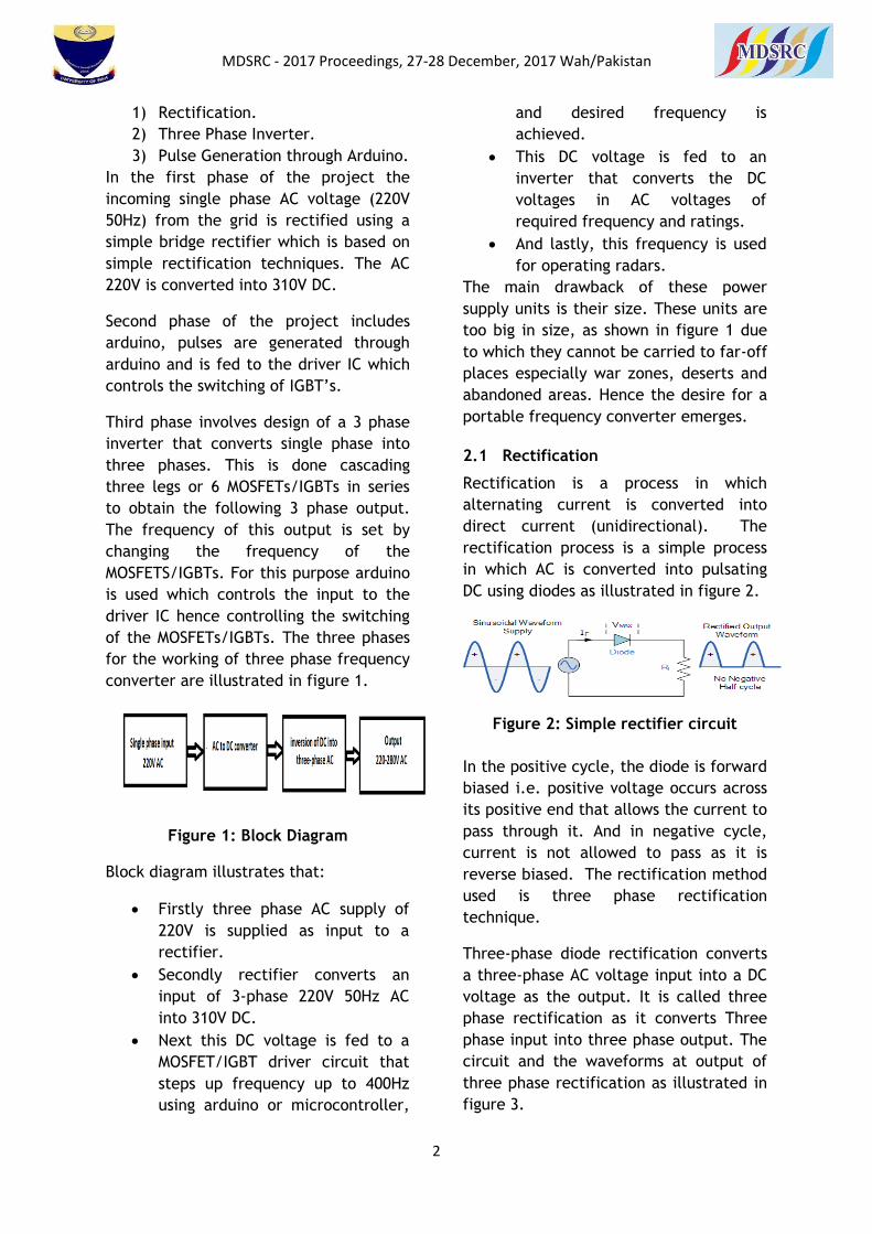
Figure 1: Block Diagram
Block diagram illustrates that:
Firstly three phase AC supply of
220V is supplied as input to a
rectifier.
Secondly rectifier converts an
input of 3-phase 220V 50Hz AC
into 310V DC.
Next this DC voltage is fed to a
MOSFET/IGBT driver circuit that
steps up frequency up to 400Hz
using arduino or microcontroller,
and desired frequency is
achieved.
This DC voltage is fed to an
inverter that converts the DC
voltages in AC voltages of
required frequency and ratings.
And lastly, this frequency is used
for operating radars.
The main drawback of these power
supply units is their size. These units are
too big in size, as shown in figure 1 due
to which they cannot be carried to far-off
places especially war zones, deserts and
abandoned areas. Hence the desire for a
portable frequency converter emerges.
2.1 Rectification
Rectification is a process in which
alternating current is converted into
direct current (unidirectional). The
rectification process is a simple process
in which AC is converted into pulsating
DC using diodes as illustrated in figure 2.
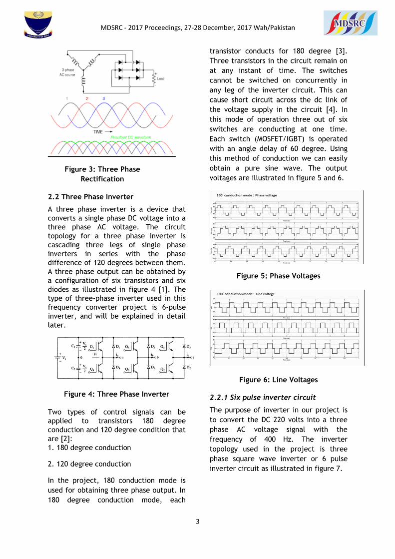
Figure 2: Simple rectifier circuit
In the positive cycle, the diode is forward
biased i.e. positive voltage occurs across
its positive end that allows the current to
pass through it. And in negative cycle,
current is not allowed to pass as it is
reverse biased. The rectification method
used is three phase rectification
technique.
Three-phase diode rectification converts
a three-phase AC voltage input into a DC
voltage as the output. It is called three
phase rectification as it converts Three
phase input into three phase output. The
circuit and the waveforms at output of
three phase rectification as illustrated in
figure 3.
MDSRC - 2017 Proceedings, 27-28 December, 2017 Wah/Pakistan
3
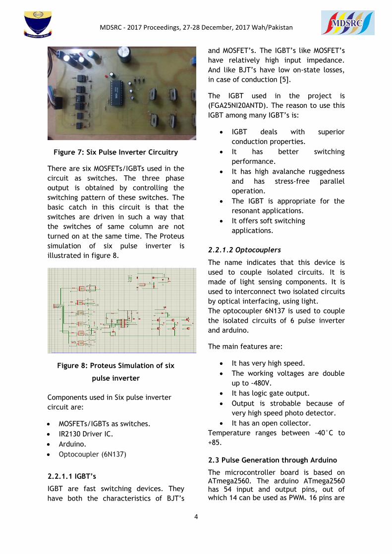
Figure 3: Three Phase
Rectification
2.2 Three Phase Inverter
A three phase inverter is a device that
converts a single phase DC voltage into a
three phase AC voltage. The circuit
topology for a three phase inverter is
cascading three legs of single phase
inverters in series with the phase
difference of 120 degrees between them.
A three phase output can be obtained by
a configuration of six transistors and six
diodes as illustrated in figure 4 [1]. The
type of three-phase inverter used in this
frequency converter project is 6-pulse
inverter, and will be explained in detail
later.
Figure 4: Three Phase Inverter
Two types of control signals can be
applied to transistors 180 degree
conduction and 120 degree condition that
are [2]:
1. 180 degree conduction
2. 120 degree conduction
In the project, 180 conduction mode is
used for obtaining three phase output. In
180 degree conduction mode, each
transistor conducts for 180 degree [3].
Three transistors in the circuit remain on
at any instant of time. The switches
cannot be switched on concurrently in
any leg of the inverter circuit. This can
cause short circuit across the dc link of
the voltage supply in the circuit [4]. In
this mode of operation three out of six
switches are conducting at one time.
Each switch (MOSFET/IGBT) is operated
with an angle delay of 60 degree. Using
this method of conduction we can easily
obtain a pure sine wave. The output
voltages are illustrated in figure 5 and 6.
Figure 5: Phase Voltages
Figure 6: Line Voltages
2.2.1 Six pulse inverter circuit
The purpose of inverter in our project is
to convert the DC 220 volts into a three
phase AC voltage signal with the
frequency of 400 Hz. The inverter
topology used in the project is three
phase square wave inverter or 6 pulse
inverter circuit as illustrated in figure 7.
MDSRC - 2017 Proceedings, 27-28 December, 2017 Wah/Pakistan
4
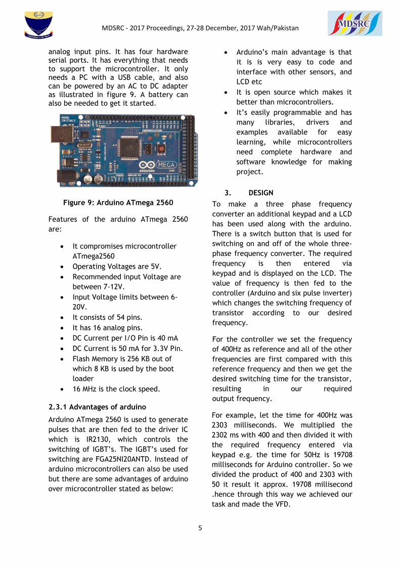
Figure 7: Six Pulse Inverter Circuitry
There are six MOSFETs/IGBTs used in the
circuit as switches. The three phase
output is obtained by controlling the
switching pattern of these switches. The
basic catch in this circuit is that the
switches are driven in such a way that
the switches of same column are not
turned on at the same time. The Proteus
simulation of six pulse inverter is
illustrated in figure 8.
Figure 8: Proteus Simulation of six
pulse inverter
Components used in Six pulse inverter
circuit are:
MOSFETs/IGBTs as switches.
IR2130 Driver IC.
Arduino.
Optocoupler (6N137)
2.2.1.1 IGBT’s
IGBT are fast switching devices. They
have both the characteristics of BJT’s
and MOSFET’s. The IGBT’s like MOSFET’s
have relatively high input impedance.
And like BJT’s have low on-state losses,
in case of conduction [5].
The IGBT used in the project is
(FGA25NI20ANTD). The reason to use this
IGBT among many IGBT’s is:
IGBT deals with superior
conduction properties.
It has better switching
performance.
It has high avalanche ruggedness
and has stress-free parallel
operation.
The IGBT is appropriate for the
resonant applications.
It offers soft switching
applications.
2.2.1.2 Optocouplers
The name indicates that this device is
used to couple isolated circuits. It is
made of light sensing components. It is
used to interconnect two isolated circuits
by optical interfacing, using light.
The optocoupler 6N137 is used to couple
the isolated circuits of 6 pulse inverter
and arduino.
The main features are:
It has very high speed.
The working voltages are double
up to -480V.
It has logic gate output.
Output is strobable because of
very high speed photo detector.
It has an open collector.
Temperature ranges between -40°C to
+85.
2.3 Pulse Generation through Arduino
The microcontroller board is based on ATmega2560. The arduino ATmega2560 has 54 input and output pins, out of which 14 can be used as PWM. 16 pins are
MDSRC - 2017 Proceedings, 27-28 December, 2017 Wah/Pakistan
5
analog input pins. It has four hardware serial ports. It has everything that needs to support the microcontroller. It only needs a PC with a USB cable, and also can be powered by an AC to DC adapter as illustrated in figure 9. A battery can also be needed to get it started.
Figure 9: Arduino ATmega 2560
Features of the arduino ATmega 2560
are:
It compromises microcontroller
ATmega2560
Operating Voltages are 5V.
Recommended input Voltage are
between 7-12V.
Input Voltage limits between 6-
20V.
It consists of 54 pins.
It has 16 analog pins.
DC Current per I/O Pin is 40 mA
DC Current is 50 mA for 3.3V Pin.
Flash Memory is 256 KB out of
which 8 KB is used by the boot
loader
16 MHz is the clock speed.
2.3.1 Advantages of arduino
Arduino ATmega 2560 is used to generate
pulses that are then fed to the driver IC
which is IR2130, which controls the
switching of IGBT’s. The IGBT’s used for
switching are FGA25NI20ANTD. Instead of
arduino microcontrollers can also be used
but there are some advantages of arduino
over microcontroller stated as below:
Arduino’s main advantage is that
it is is very easy to code and
interface with other sensors, and
LCD etc
It is open source which makes it
better than microcontrollers.
It’s easily programmable and has
many libraries, drivers and
examples available for easy
learning, while microcontrollers
need complete hardware and
software knowledge for making
project.
3. DESIGN
To make a three phase frequency
converter an additional keypad and a LCD
has been used along with the arduino.
There is a switch button that is used for
switching on and off of the whole three-
phase frequency converter. The required
frequency is then entered via
keypad and is displayed on the LCD. The
value of frequency is then fed to the
controller (Arduino and six pulse inverter)
which changes the switching frequency of
transistor according to our desired
frequency.
For the controller we set the frequency
of 400Hz as reference and all of the other
frequencies are first compared with this
reference frequency and then we get the
desired switching time for the transistor,
resulting in our required
output frequency.
For example, let the time for 400Hz was
2303 milliseconds. We multiplied the
2302 ms with 400 and then divided it with
the required frequency entered via
keypad e.g. the time for 50Hz is 19708
milliseconds for Arduino controller. So we
divided the product of 400 and 2303 with
50 it result it approx. 19708 millisecond
.hence through this way we achieved our
task and made the VFD.
MDSRC - 2017 Proceedings, 27-28 December, 2017 Wah/Pakistan
6
4. RESULTS AND DISCUSSIONS
The project’s main goal is to convert
conventional frequency of 50 Hz into
desirable frequency of 400 Hz, as many
machines and devices operate on this
frequency like radars. For calculation of
results a digital oscilloscope is used. The
digital oscilloscope shows the desired
waveforms of line to line and line to
neutral voltages of a three-phase 6 pulse
inverter circuit. Frequency and other
parameters like time period, rise time,
fall time and RMS voltages are also
determined.
The project is capable of obtaining
desired frequencies other than only the
reference frequency i.e. is 400Hz. We
will obtain calculations for different
frequencies for verifying our results
accuracy.
4.1 CASE 1 (50 Hz)
The desired frequency is fed to the
arduino through the keypad feature and
the oscilloscope displays the required
frequency that is converted with help of
6 pulse driver circuitry and VFD together.
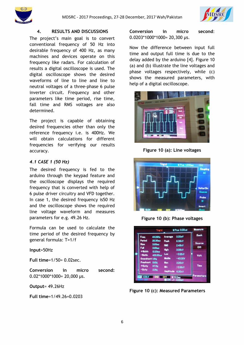
In case 1, the desired frequency is50 Hz
and the oscilloscope shows the required
line voltage waveform and measures
parameters for e.g. 49.26 Hz.
Formula can be used to calculate the
time period of the desired frequency by
general formula: T=1/f
Input=50Hz
Full time=1/50= 0.02sec.
Conversion in micro second:
0.02*1000*1000= 20,000 µs.
Output= 49.26Hz
Full time=1/49.26=0.0203
Conversion in micro second:
0.0203*1000*1000= 20,300 µs.
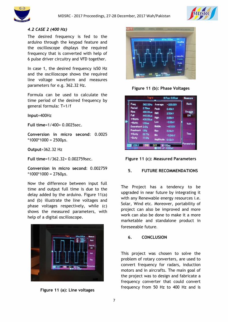
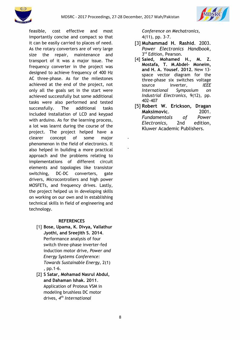
Now the difference between input full
time and output full time is due to the
delay added by the arduino [4]. Figure 10
(a) and (b) illustrate the line voltages and
phase voltages respectively, while (c)
shows the measured parameters, with
help of a digital oscilloscope.
Figure 10 (a): Line voltages
Figure 10 (b): Phase voltages
Figure 10 (c): Measured Parameters
MDSRC - 2017 Proceedings, 27-28 December, 2017 Wah/Pakistan
7
4.2 CASE 2 (400 Hz)
The desired frequency is fed to the
arduino through the keypad feature and
the oscilloscope displays the required
frequency that is converted with help of
6 pulse driver circuitry and VFD together.
In case 1, the desired frequency is50 Hz
and the oscilloscope shows the required
line voltage waveform and measures
parameters for e.g. 362.32 Hz.
Formula can be used to calculate the
time period of the desired frequency by
general formula: T=1/f
Input=400Hz
Full time=1/400= 0.0025sec.
Conversion in micro second: 0.0025
*1000*1000 = 2500µs.
Output=362.32 Hz
Full time=1/362.32= 0.002759sec.
Conversion in micro second: 0.002759
*1000*1000 = 2760µs.
Now the difference between input full
time and output full time is due to the
delay added by the arduino. Figure 11(a)
and (b) illustrate the line voltages and
phase voltages respectively, while (c)
shows the measured parameters, with
help of a digital oscilloscope.
Figure 11 (a): Line voltages
Figure 11 (b): Phase Voltages
Figure 11 (c): Measured Parameters
5. FUTURE RECOMMENDATIONS
The Project has a tendency to be
upgraded in near future by integrating it
with any Renewable energy resources i.e.
Solar, Wind etc. Moreover, portability of
project can also be improved and more
work can also be done to make it a more
marketable and standalone product in
foreseeable future.
6. CONCLUSION
This project was chosen to solve the
problem of rotary converters, are used to
convert frequency for radars, induction
motors and in aircrafts. The main goal of
the project was to design and fabricate a
frequency converter that could convert
frequency from 50 Hz to 400 Hz and is
MDSRC - 2017 Proceedings, 27-28 December, 2017 Wah/Pakistan
8
feasible, cost effective and most
importantly concise and compact so that
it can be easily carried to places of need.
As the rotary converters are of very large
size the repair, maintenance and
transport of it was a major issue. The
frequency converter in the project was
designed to achieve frequency of 400 Hz
AC three-phase. As for the milestones
achieved at the end of the project, not
only all the goals set in the start were
achieved successfully but some additional
tasks were also performed and tested
successfully. The additional tasks
included installation of LCD and keypad
with arduino. As for the learning process,
a lot was learnt during the course of the
project. The project helped have a
clearer concept of some major
phenomenon in the field of electronics. It
also helped in building a more practical
approach and the problems relating to
implementations of different circuit
elements and topologies like transistor
switching, DC-DC converters, gate
drivers, Microcontrollers and high power
MOSFETs, and frequency drives. Lastly,
the project helped us in developing skills
on working on our own and in establishing
technical skills in field of engineering and
technology.
REFERENCES
[1] Bose, Upama, K. Divya, Vallathur
Jyothi, and Sreejith S. 2014.
Performance analysis of four
switch three-phase inverter-fed
induction motor drive, Power and
Energy Systems Conference:
Towards Sustainable Energy, 2(1)
, pp.1-6.
[2] S Satar, Mohamad Nasrul Abdul,
and Dahaman Ishak. 2011.
Application of Proteus VSM in
modeling brushless DC motor
drives, 4th International
Conference on Mechatronics,
4(11), pp. 3-7.
[3] Muhammad H. Rashid. 2003. Power Electronics Handbook, 3rd Edition, Pearson.
[4] Saied, Mohamed H., M. Z. Mostafa, T. M.Abdel- Moneim, and H. A. Yousef. 2012. New 13-space vector diagram for the three-phase six switches voltage source inverter, IEEE International Symposium on Industrial Electronics, 9(12), pp. 402-407
[5] Robert W. Erickson, Dragan Maksimovic. 2001. Fundamentals of Power Electronics, 2nd edition, Kluwer Academic Publishers.
.
.


![Proceedings : December 27 - 29, 2010, [held at IIT Kharagpur]](https://static.fdocuments.in/doc/165x107/586a169e1a28abab4a8bb2cb/proceedings-december-27-29-2010-held-at-iit-kharagpur.jpg)