apple shake strawberry shake Today, let’s make a banana milk shake together~

MDOF Hybrid Shake Table Testing for Bridge and Building Structures
Andreas Schellenberg, Ph.D., P.E.Shawn You, Ph.D., P.E.Stephen Mahin, Ph.D.
EU-US-Asia workshop on hybrid testingIspra, 5-6 October 2015
2
1. Motivation2. Hybrid Shake Table Testing3. Stability and Accuracy Considerations4. Test Rehearsal and Safety Precautions5. Bridge Application6. Building Application7. Summary & Conclusions
Outline of Presentation

MotivationMany structures exhibit significant rate of
loading effectsNeed testing to occur at or near real timeLarge systems such as tall buildings, long-
span bridges, or SFSI are difficult to test on shake tables
Shaking Table Numerical Model
Hybrid Shake Table
Numerical ModelShaking Table
Hybrid Shake Table
3
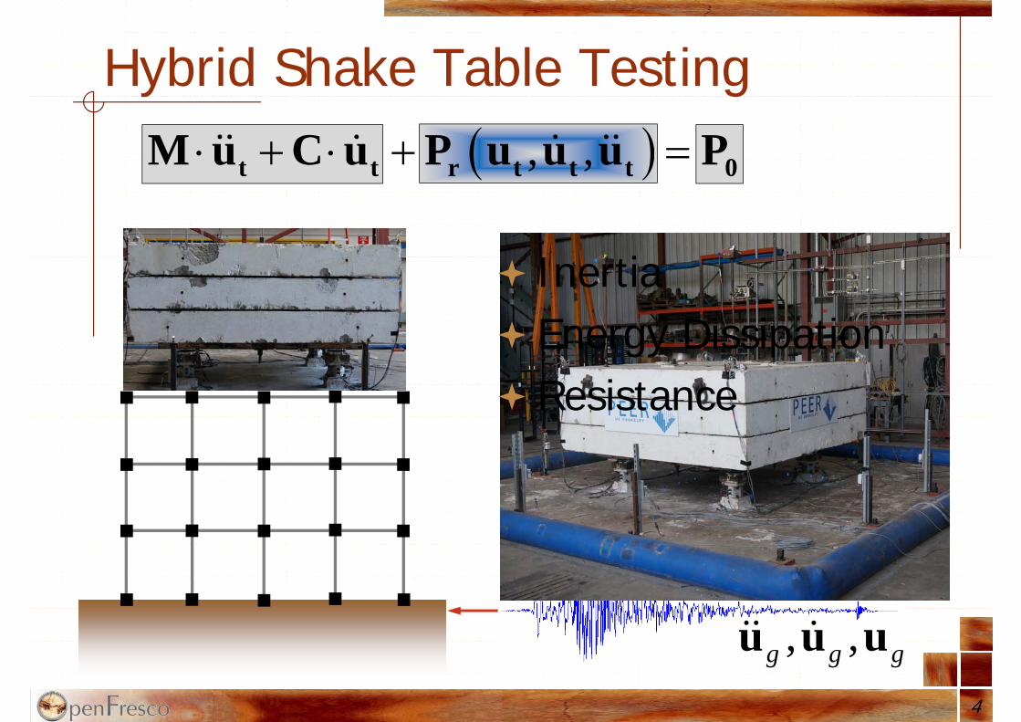
, ,g g gu u u
Hybrid Shake Table Testing
4
Inertia Energy Dissipation Resistance
, , t t r t t t 0M u C u P u u u P

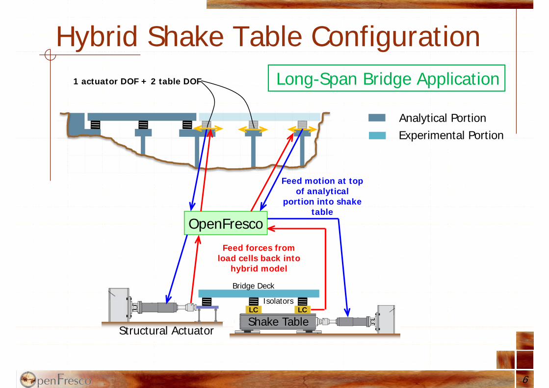
Hybrid Shake Table Configuration
ExperimentalPortion
AnalyticalPortion
ExperimentalPortion
Shake Table
Feed motion at top of analytical
portion into shake table
OpenFresco
Feed forces from load cells back into
hybrid model
LC LC
5
Tall Building Application
3 translational DOF + 3 rotational DOF
Hybrid Shake Table Configuration
6
Shake TableLCLC
Analytical Portion
OpenFresco
Structural Actuator
Experimental Portion
Isolators
Bridge Deck
Feed forces from load cells back into
hybrid model
Feed motion at top of analytical
portion into shake table
Long-Span Bridge Application1 actuator DOF + 2 table DOF
Important Analysis ParametersOpenSees or OpenSeesSP as comp. driverUsing AlphaOSGeneralized (inf = 0)No iterations necessaryUsing MultipleSupport excitation pattern
in OpenSees to get absolute responseGravity loads on test specimen always
present apply gravity loads to numerical portion before connecting with shake table + apply disp. commands relative to start of test
7
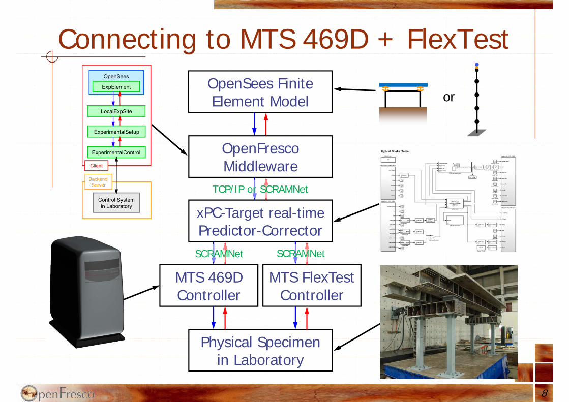
OpenSees Finite Element Model
OpenFrescoMiddleware
xPC-Target real-timePredictor-Corrector
Physical Specimenin Laboratory
MTS 469D Controller
Connecting to MTS 469D + FlexTest
8
TCP/IP or SCRAMNet
SCRAMNet
MTS FlexTestController
SCRAMNet
or
Improving Stability & AccuracyDelay compensation is essential for real-
time hybrid simulations (RTHS)Use Adaptive Time Series (ATS) delay
compensator (by Y. Chae)Modify ATS to use target velocities and
accelerations computed by predictor-corrector algorithm instead of taking derivatives of target displacements
Use stabilization and loop-shapingSensor noise reduction by filtering fbk
9

Test Rehearsal
10
Use FE-Adapter element method to simultaneously connect hybrid model to a numerically simulated test specimen
OpenSees
ExpElement
ExperimentalSetup
ECxPCtarget
LocalExpSite
Control Systemin Laboratory
BackendServer
Client
ShadowExpElement
ExperimentalSetup
ECSimFEAdapter
LocalExpSite
FE-Software
BackendServer
AdapterElement0% 100%

Safety PrecautionsAt analysis side
Set limit on displacement command (saturation and possibly rate limit)
Set limit on actuator force so that once the limit is exceeded, the analysis model sends displacement commands to ramp both table and actuator to starting positions
At controller side Set both displacement and force limits so that once
the limit is exceeded, the actuator pressure is switched to low, therefore, limiting the actuator force that can be applied to the specimen
11
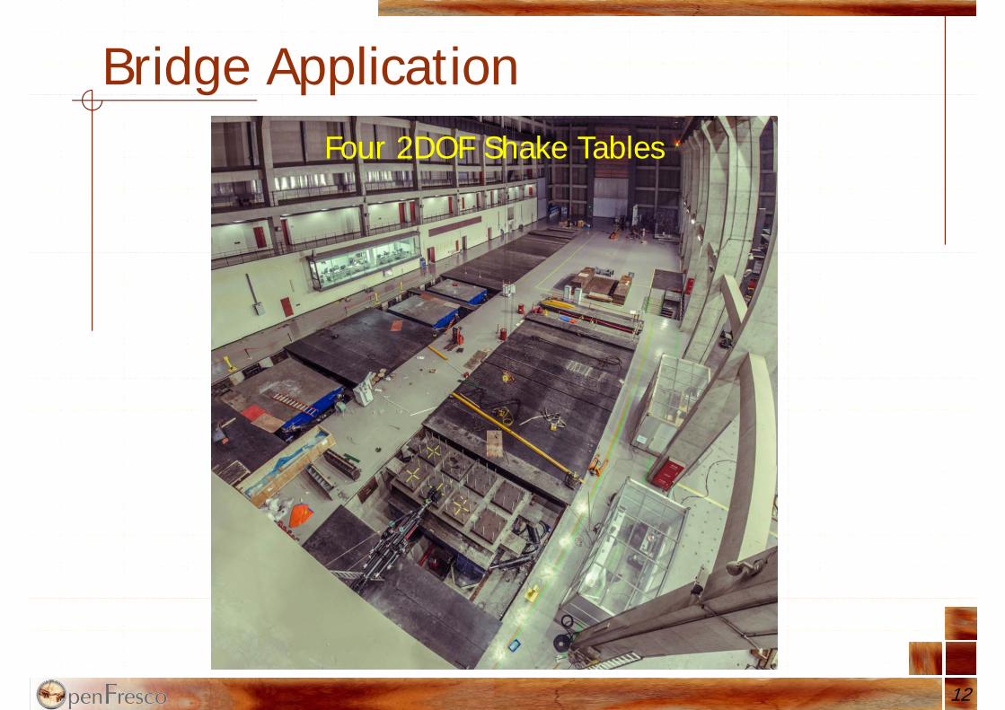
Bridge Application
12
Four 2DOF Shake Tables
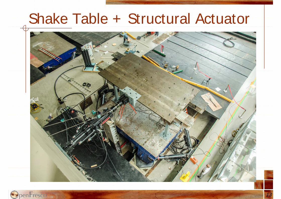
Shake Table + Structural Actuator
13

Hybrid Model Development
ExpBridge
Simplified Hybrid OpenSees Model of Bridge (Stage 2)
Soil
experimental bridgewith partial bridge deck
weightRemaining numerical mass
Actual Bridge Configuration (with foundation + soil)
14
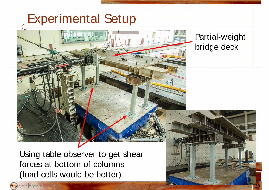
Experimental SetupPartial-weight bridge deck
Using table observer to get shear forces at bottom of columns(load cells would be better)
15
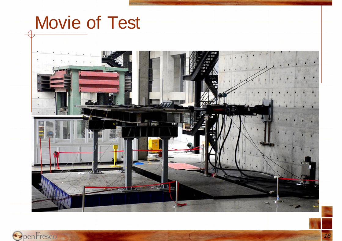
Movie of Test
16
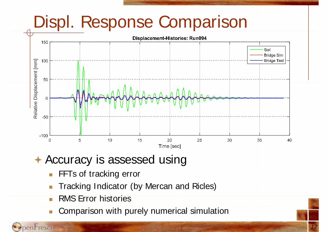
Displ. Response ComparisonR
elat
ive
Dis
plac
emen
t [m
m]
17
Accuracy is assessed using FFTs of tracking error Tracking Indicator (by Mercan and Ricles) RMS Error histories Comparison with purely numerical simulation
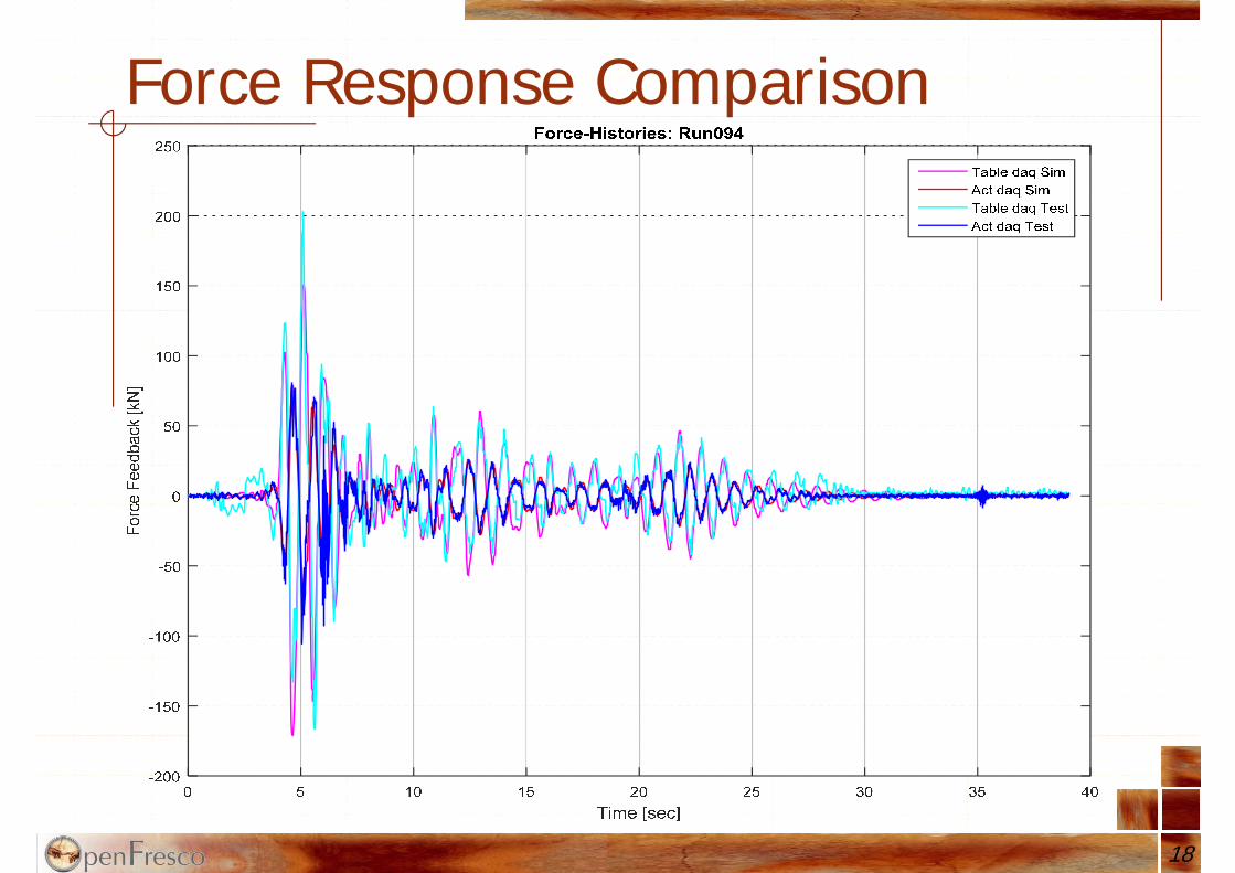
Force Response Comparison
18
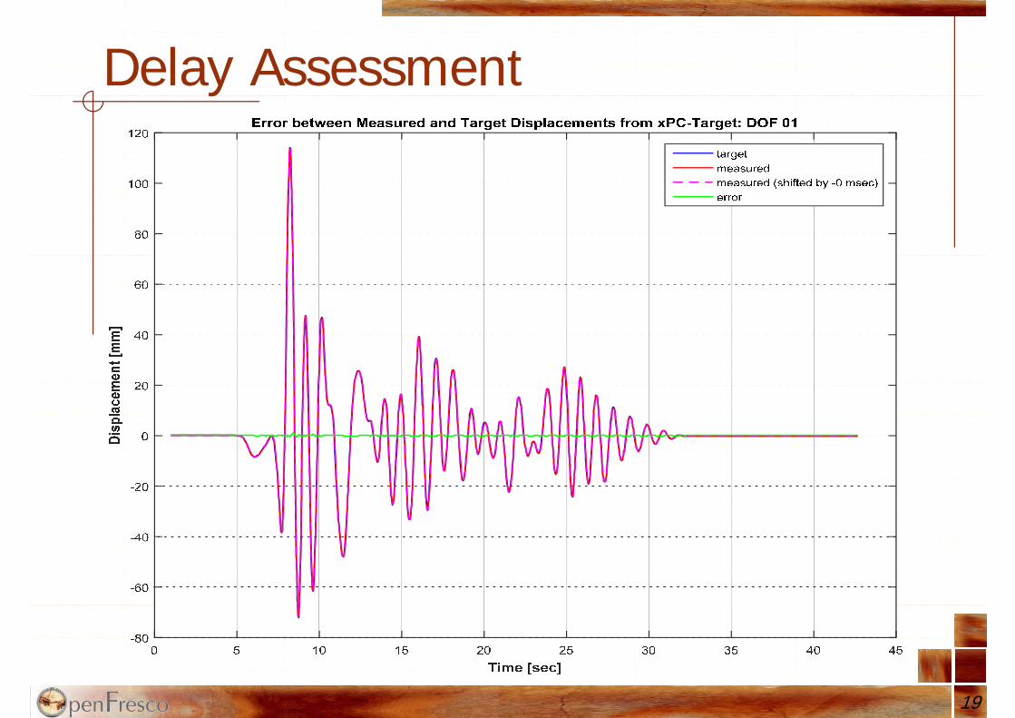
Delay Assessment
19
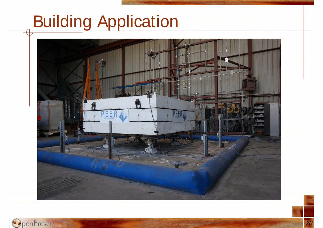
Building Application
20

Triple Friction Pendulum Bearings
21
L1 (in.) L2 (in.) L3 (in.)
2.175 17.17 17.17
T1 (s) T2 (s) T3 (s)
0.67 1.41 1.87
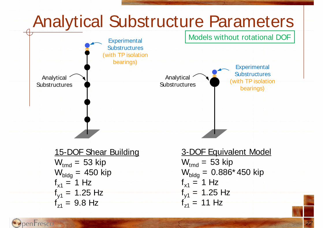
Analytical Substructure Parameters
22
Analytical Substructures
Experimental Substructures
(with TP isolation bearings)
15-DOF Shear BuildingWtmd = 53 kipWbldg = 450 kipfx1 = 1 Hzfy1 = 1.25 Hzfz1 = 9.8 Hz
Analytical Substructures
Experimental Substructures
(with TP isolation bearings)
3-DOF Equivalent ModelWtmd = 53 kipWbldg = 0.886*450 kipfx1 = 1 Hzfy1 = 1.25 Hzfz1 = 11 Hz
Models without rotational DOF
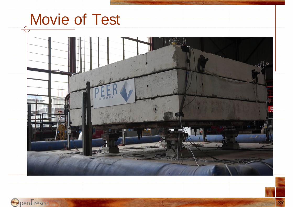
Movie of Test
23
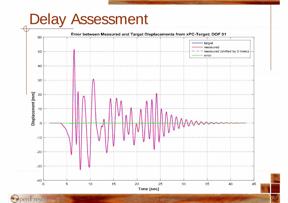
Delay Assessment
24

Delay Assessment
25
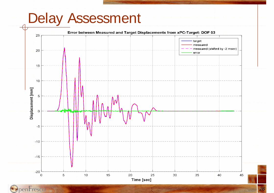
Delay Assessment
26

Tracking Indicator
27

Summary & ConclusionsAbility to drive a MDOF shake table
through a finite element modelShake table platform can thus represent a
floor or the roof of a building, the motion on top of a bridge column, or the ground surface on top of a soil domain
Performed large-scale RTHS where a shake table is combined with a dynamic structural actuator applied to a bridge
Ability to perform parameter studies
28
Summary & ConclusionsUse whenever the dynamics of the test
specimen significantly affects the response of the supporting structure or soil and, therefore, alters the required input to the shake table as testing progresses
ATS delay compensator worked very wellNeed to further investigate sensor noise
reduction methods to improve feedback signals (look into Kalman filters)
29
Questions?Thank you!
http://openfresco.berkeley.edu
EU-US-Asia workshop on hybrid testingIspra, 5-6 October 2015