![Animales marinos[1]](https://static.fdocuments.in/doc/165x107/54b9c5dc4a795976118b46d8/animales-marinos1.jpg)
Mcneil lake Dam STABILITY ANALYSIS · Marinos, P and Hoek, E. 2000 GSI – A geologically friendly...
71
SUNSHINE COAST REGIONAL DISTRICT MCNEIL LAKE DAM STABILITY ANALYSIS REPORT NOVEMBER 2013 ISSUED FOR USE
Transcript of Mcneil lake Dam STABILITY ANALYSIS · Marinos, P and Hoek, E. 2000 GSI – A geologically friendly...

SUNSHINE COAST REGIONAL DISTRICT
MCNEIL LAKE DAM STABILITY ANALYSIS
REPORT
NOVEMBER 2013 ISSUED FOR USE

MCNEIL LAKE DAM STABILITY ANALYSIS
NOVEMBER 2013 | ISSUED FOR USE
Tetra Tech, Inc. 400 112th Avenue NE
Bellevue, WA 98144 USA p. 425.635.1000 f. 425.635.1150

MCNEIL LAKE DAM STABILITY ANALYSIS
NOVEMBER 2013 | ISSUED FOR USE
3
CERTIFICATE OF ENGINEER Theworkcontainedhereinwaspreparedunderthesupervisionanddirectionoftheundersigned.
CarlosChaparro,P.Eng
chris.willcox
C Chaparro PE


MCNEIL LAKE DAM STABILITY ANALYSIS
NOVEMBER 2013 | ISSUED FOR USE
i
EXECUTIVE SUMMARY
Based on the results and recommendations of a Dam Safety Review conducted in 2012 by EBA Engineering
Consultants Ltd. (operating as EBA, a Tetra Tech Company), Tetra Tech was retained by the Sunshine Coast
Regional District to conduct a detailed stability analysis for McNeil Lake Dam, which is located in the South
Pender Harbour Waterworks District (SPHWD), BC. McNeil Lake Dam is a concrete buttress dam 18.3 m
long and 4.0 m high. The dam was raised by 0.9 m in 1976 and concrete buttresses were added. There is a
4.0 m wide spillway fitted with stoplogs and a low level sluice gate at the base of the dam.
The Dam Safety Review concluded that a consequence classification of “High” is appropriate for this dam;
that in accordance with current standards, the appropriate inflow design flood (IDF) for this classification
is one-third of the way between a 1000-year flood and the Probable Maximum Flood; and that the
corresponding design seismic event has a 2500-year return period. The hydrotechnical assessment of the
spillway from the Dam Safety Review indicated that the dam would be overtopped by 1.8 m under design
flood conditions.
A basic stability analysis performed as part of the Dam Safety Review indicated that the dam did not meet
the required overturning and sliding factors of safety for the seismic and design flood conditions, and
recommended that a more detailed analysis be undertaken to confirm those results or to show that the
dam had adequate stability.
A site visit was carried out by personnel from EBA and Tetra Tech on July 29, 2013. At the time of the site
visit, the dam was not overflowing and the downstream face and toe of the dam were visible. The dam was
found to be generally in good condition with some erosion in the bedrock at the base of one of the
buttresses. It was observed that the rock below the base of that buttress had not been excavated to provide
a sloped bearing as called for in the design drawings for the 1976 dam raise. This condition has the effect
of somewhat reducing the sliding resistance of the dam.
Using the 1976 design drawing from the dam raise, which shows the current as-designed condition of the
dam, and the observations from the site visit, a stability analysis of each of the four main buttresses and of
the tallest portion of the wing wall was undertaken. This detailed stability analysis confirmed that the dam
does not meet the required factors of safety for overturning and sliding for the design flood and seismic
conditions.
In accordance with the scope of services, both potential further analysis and basic retrofit schemes were
considered. Based on the results of the stability analysis, it was concluded that more sophisticated analysis
methods, such as 3-D finite element modeling would be unlikely to change the results. Therefore, a basic
retrofit scheme involving the installation of vertical rock anchors from the crest of the dam was developed
and estimated quantities were calculated. It is estimated that approximately nine 32 mm diameter rock
anchors installed to a depth of 8 meters below the crest would be required to achieve the required stability
criteria.


MCNEIL LAKE DAM STABILITY ANALYSIS
NOVEMBER 2013 | ISSUED FOR USE
i
TABLE OF CONTENTS
EXECUTIVE SUMMARY........................................................................................................................... i
1.0 INTRODUCTION ........................................................................................................................... 1
2.0 SUMMARY OF 2012 DAM SAFETY REVIEW ............................................................................. 1
3.0 SITE VISIT ........................................................................................................................................ 2
4.0 GEOTECHNICAL EVALUATION ................................................................................................ 2
5.0 STABILITY ANALYSIS .................................................................................................................. 3
5.1 Loading Conditions and Acceptance Criteria ........................................................................................ 3
5.2 Loads ..................................................................................................................................................... 4
5.3 Analysis Description .............................................................................................................................. 4
5.4 Calculations ........................................................................................................................................... 5
5.5 Summary of Analysis Results ................................................................................................................ 5
5.6 Retrofit Analysis ..................................................................................................................................... 6
6.0 CONCLUSIONS AND RECOMMENDATIONS .......................................................................... 6
6.1 Conclusions ........................................................................................................................................... 6
6.2 Recommendations ................................................................................................................................. 7
7.0 CLOSURE ......................................................................................................................................... 7
PHOTOGRAPHS
Photo 1 Joints in buttresses, July 26, 2013
Photo 2 Seepage at Foundation, July 26, 2013
Photo 3 Erosion at Buttress Base, July 26, 2013
Photo 4 Toe Slab Cracking at Buttress Base, July 26, 2013
Photo 5 Right (North) Buttress, July 26, 2013
Photo 6 Left (South) Buttress July 26, 2013
APPENDICES
Appendix A
Appendix B
Appendix C
Stability Calculations
Geotechnical Calculations
Seismic Ground Accelerations


MCNEIL LAKE DAM STABILITY ANALYSIS
NOVEMBER 2013 | ISSUED FOR USE
1
1.0 INTRODUCTION
In December 2011, the Sunshine Coast Regional District (SCRD) retained EBA, A Tetra Tech Company,
to conduct a Dam Safety Review for McNeil Lake Dam, which is located in the Pender Harbour area of the
Sunshine Coast Regional District, BC. The scope of work for the review included:
Background data and record review;
Site inspection and staff interviews;
Dam consequence classification;
Dam safety analysis;
Dam Safety Management system review; and
Dam Safety Review report.
This Dam Safety Review (EBA, 2012) was completed in October 2012 and included a stability analysis that
showed potential instability under the seismic and design flood conditions.
In July 2013, the SCRD retained Tetra Tech to perform a more detailed stability analysis of McNeil Lake
Dam in accordance with the requirements of the British Columbia Dam Safety Regulation (Queen’s Printer,
2011), and the Canadian Dam Association (CDA) guidelines (CDA, 2007). The scope for this work included
the stability analysis, a report on the results and, if the instabilities were confirmed, a general scheme and
approximate quantities for a retrofit to provide the required stability.
2.0 SUMMARY OF 2012 DAM SAFETY REVIEW
The Dam Safety Review undertaken by EBA developed the following conclusions (EBA, 2012):
A simplified dam break analysis has shown that a dam failure would generate a flood wave that would
reach the Sunshine Coast Highway in eight minutes. Assessment of the incremental consequences of dam failure places the dam in the High classification.
The recommended Inflow Design flood is therefore 1/3 between the 1000-year flood and the Probable Maximum Flood and the design earthquake is to have a return period of 1:2500 years, according to the BC Dam Safety Regulation.
The inflow design flow was determined to have a peak inflow of 117.6 m3/s. Routing of the inflow design flood through the reservoir and spillway showed that the dam would be overtopped by 1.84 m.
McNeil Lake Dam has an acceptable level of seepage.
It is judged there has been negligible movement of the dam.
A simplified stability analysis indicate that the structure does not meet the required criteria.
A dam safety expectation analysis found five Actual Deficiencies, one Potential Deficiency and seven Non-conformances.

MCNEIL LAKE DAM STABILITY ANALYSIS
NOVEMBER 2013 | ISSUED FOR USE
2
Based on these conclusions, a number of recommendations were developed. The primary recommendation
related to the dam stability was for SCRD to undertake a more detailed analysis to establish with more
certainty the actual stability of the dam. The Review also recommended that a surveillance program should
be initiated to track the condition of the concrete and the foundation rock as well as the volume of seepage.
3.0 SITE VISIT
Chris Willcox, P.E. (Tetra Tech) and Carlos Chaparro, P. Eng (EBA) visited the site on July 29, 2013
accompanied by Monte Staats (SCRD) and Brandon Lafortune (SCRD).
Since the site visits made for the Dam Safety Review, a walkway across the spillway has been added,
making it possible to walk the full length of the dam and view both abutments. In addition, at the time of
the visit the dam was not overflowing, allowing observation of the downstream face, the dam toe, and the
foundation rock at the base of the dam. Aside from some minor damage at cold joints in the buttresses
(Photo 1), the concrete was in good condition and there was only minor seepage at the toe, most of which
appeared to be concentrated around joints in the foundation rock (Photo 2).
The dam has four main buttresses, with the two central buttresses extending down to the streambed.
Areas of bedrock showing some surface weathering were observed at the base at the northern buttress
(Photo 3), and large parts of the toe slab appeared to be missing. It was apparent the base of that buttress
had been placed directly against the foundation rock without the sloped base excavation shown in the
drawings of the 1976 dam raise. Cracking at the base of the other full-height buttress indicated that it was
likely placed in the same way (Photo 4). Therefore the partial embedment of the buttresses shown in the
drawings was not considered in the analysis. The foundations of the two exterior buttresses were visible
and these two foundations were embedded into the rock (Photo 5, Photo 6). This embedment was
accounted for in the analysis.
To the north of the dam, there are two sections of wing wall varying in height from approximately 1.5 m at
the end of the dam to approximately 0.3 m at its northern end where it is embedded flush with the rock in
that area.
There were two stoplogs in place raising the spillway crest to within approximately 10 cm of the dam crest.
During the site visit for the Dam Safety Review, it was reported that the stoplogs are normally installed in
May and removed in October each year. However the installation of the new walkway has covered the area
above the stop logs and it appears that they could only be removed with some difficulty. Therefore, for the
purposes of this stability analysis it has been assumed that the stop logs are permanently left in place.
4.0 GEOTECHNICAL EVALUATION
The characteristics of the bedrock observed immediately downstream of the dam are described below:
In general the rock is very strong, blocky to massive granodiorite with reddish surface coating.
The rock mass quality at the back of the dam was assessed using the Hoek-Brown Geological Strength
Index, GSI (Hoek and Marinos, 2000) which depends on the rock mass fabric and the condition of these
structures. The GSI values were assigned using engineering judgment based on the observed geotechnical

MCNEIL LAKE DAM STABILITY ANALYSIS
NOVEMBER 2013 | ISSUED FOR USE
3
characteristics during the site visit. The characterization does not consider a unique value GSI value but a
'typical' range for each wall of the pit assessed. The observed range of GSI values is between 60-75,
indicating the rock is of good conditions.
Persistence of joints tend to be larger than 4 m with spacing varying between 0.2-1.0 m
Two clear joint sets were observed;
- A tight semi-vertical set perpendicular to the alignment of the dam. This set tends to be smooth to
rough and planar to stepped.
- A semi-horizontal joint set, striking between 0 to 30° from the alignment of the dam and dipping
between 0 to 20°. This set tends to be smooth to rough and undulated to stepped.
The bedrock surface seems to be stepped and undulating, exhibiting surface irregularities (asperities).
Based on the observed condition of the bedrock, the following parameters were used in the analysis for the
concrete-to-bedrock interface:
Friction angle: 36°
Cohesion: 0 kPa, in the absence of testing
5.0 STABILITY ANALYSIS
5.1 Loading Conditions and Acceptance Criteria
The applicable loading combinations are provided in the Technical Bulletin “Structural Considerations for
Dam Safety” in the 2007 CDA Dam Safety Guidelines. They include:
Usual Loading: Permanent and operating loads including self-weight, ice, silt, earth pressure and normal
maximum operating water level with appropriate uplift pressures and tailrace level.
Extreme Loading – IDF Flooding: Includes all usual loads except ice, in conjunction with reservoir,
tailrace and uplift resulting from the Inflow Design Flood.
Extreme Loading – Earthquake: permanent and operating loads from the usual case minus ice in
conjunction with seismic loads. For the “High” consequence classification, the design seismic event has
a 2475-year return period.
The acceptance criteria are provided in Section 8 of the CDA document and include:
Position of Resultant Usual – within the middle third (100% of base in compression)
Extreme – within the base
Sliding Factor of Safety Usual ≥ 1.5 (no cohesion used)
Usual ≥ 2.0 (cohesion used and validate with testing)
Extreme Flood ≥ 1.1
MCNEIL LAKE DAM STABILITY ANALYSIS
NOVEMBER 2013 | ISSUED FOR USE
4
5.2 Loads
The loading assumptions were used in the stability analysis:
Uplift Pressure – For load conditions with no net tension at the heel of the dam, a triangular
distribution from the reservoir headwater pressure at the heel of the dam to the tailwater pressure at
the downstream toe is used. For both the usual and seismic load cases, the tailwater pressure was
assumed to be zero. For conditions where tension occurred at the heel of the dam, cracking was
assumed, with the full headwater pressure acting on the length of the crack and a triangular
distribution from the headwater pressure at the end of the crack to the tailwater pressure at the toe.
Due to the damage to the toe slab, it has been neglected both for the determination of the uplift
pressure and for calculation of resistance to overturning and sliding.
Silt Loading – Based on the observations from the site visit made for the Dam Safety Review, no silt
load was used in this stability assessment.
Ice Loading – based on the observation that there is flow over the dam all winter, ice loading was not
applied
Flood Level – the hydrologic evaluation in the Dam Safety Review (EBA, 2012) calculated a lake level at
the IDF of 1.8 m above the dam crest.
Seismic Loading - the consequence classification of this facility was judged to be High, therefore the
seismic coefficient corresponding to a 1:2475 year event—which is equivalent to a 2% chance of
exceedance in 50 years—is to be used for the analysis. The peak ground acceleration (PGA) for this
site was determined using the Seismic Hazard Calculator for the 2010 National Building Code (NBC) at
the Earthquakes Canada website (http://www.earthquakescanada.nrcan.gc.ca/hazard-alea/
interpolat/index_2010-eng.php) As shown in the calculation attached in Appendix C, the PGA was
determined to be 0.38 g.
An initial assessment was performed using the pseudostatic method with a seismic coefficient of 2/3
of PGA (0.25 g). The 2/3 coefficient was selected since it is the value used by the US Army Corps of
Engineers for the analysis of their dams and other retaining structures. It was found from this initial
assessment that the flood case is a more severe load condition than seismic, so no further seismic
analysis was undertaken.
5.3 Analysis Description
For the purposes of this stability assessment, each of the four main buttresses was considered separately as
the center of an independently acting rigid-body section that included the tributary portion of the dam on
each side of the buttress. The dividing points between the sections were taken midway between the
buttresses. Thus the base footprint of each of the analyzed sections was a T-section with the buttress at its
center. In the case of the two central buttresses, the dam section is the same or virtually the same on each
side of the buttress. However at the left (north) and right (south) buttresses the base elevation and
footprint are different on the two sides of the buttresses, and thus simplifying assumptions were made
about the behavior of those buttresses.

MCNEIL LAKE DAM STABILITY ANALYSIS
NOVEMBER 2013 | ISSUED FOR USE
5
In addition to the buttresses, the tallest part of the wing wall, immediately to the north of the dam, was
analyzed in a similar manner.
Where the required stability conditions were not met, a calculation was made to determine the restoring
forces that would be required to meet the CDA criteria. From those forces, the quantity of rock anchors
required to meet the stability criteria was determined. This is described further in Section 5.6.
5.4 Calculations
The stability calculations are included in Appendix A. Because the 1976 drawings used to establish the
existing dimensions are in English units, these calculations were done using English units as well.
Calculations for the capacity of the rock anchors considered for the retrofit scheme are included in
Appendix B.
The output from the Seismic Hazard Calculator on the Earthquakes Canada website is included in
Appendix C.
5.5 Summary of Analysis Results
All of the buttresses and the wing wall do not meet a required factor of safety for at least one load
condition.
For the Usual loading condition:
The two tall central buttresses (#2 and #3 in the calculations) do not have 100% of their bases in
compression and, due to the lack of the sloping excavation at their base, the sliding factor of safety is
less than 1.5.
The right buttress (#1 in the calculations) and the wing all are fully in compression and have sliding
factors of safety above 1.5
The left buttress (#4 in the calculations) has less than 100% of the base in compression, but has a
sliding factor of safety above 1.5
Some combination of cohesion and load sharing might be sufficient to create acceptable factors of
safety for overturning and sliding for the usual load case for all of the locations. However, as seen
below this is not true for the Extreme load conditions.
For the Flood load condition:
The uplift pressures are high, leading to factors of safety against sliding below 1.1 for all of the
locations checked.
In all of the locations, the resultant is outside the base, indicating overturning instability
For the Earthquake load condition:
The resultant is within the base for all of the locations analyzed.
The sliding factor of safety is below 1.0 for all locations except for Buttress #1. Because of the
transient nature of seismic loads, sliding factors of safety less than 1 indicate only instantaneous
MCNEIL LAKE DAM STABILITY ANALYSIS
NOVEMBER 2013 | ISSUED FOR USE
6
movement. Because any sliding occurs only in short bursts, the total amount of movement may be
acceptable.
In all locations, the Flood load condition is worse than the Earthquake, so the Earthquake case does
not control the required retrofit. Because of this, the actual magnitude of movement during the design
seismic event was not investigated.
This stability analysis contains a number of simplifications and some conservative assumptions. A finite
element analysis could be developed that would more realistically consider both the three-dimensional
response of the structure and the elasticity of the structure and foundation. However, given the magnitude
of the flood loading and the large margin by which the required factors of safety are surpassed, it is
extremely unlikely that such an analysis would show the dam meeting the required stability criteria.
5.6 Retrofit Analysis
As described above, where the required stability conditions were not met, a calculation was made to
determine the restoring forces that would be required to meet the CDA criteria. In order to provide the
necessary restoring forces, a retrofit scheme consisting of tiedown anchors installed vertically from the
crest through the dam into the foundation rock was considered.
Based on consultation with a local contractor, a man-portable drilling rig capable of drilling holes up to
100 mm in diameter up to approximately 8 meters in depth could be used for this work. For the purposes
of developing quantities, it was assumed that 32 mm diameter rock anchors in 65 mm holes would be used.
Using these parameters, it is estimated that a total of approximately nine (9) 32 mm diameter Grade
830/1035 MPa anchors would be needed to provide the required capacity.
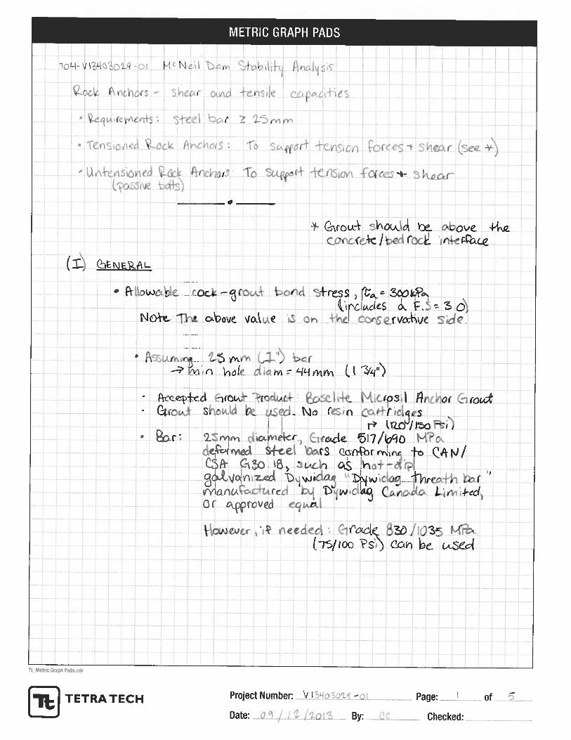
The anchor bars would be deformed steel bars conforming to CAN/CSA 630.18 such as hot-dip galvanized
Dywidag threadbar or an approved equal. (It should be noted that the calculations are based on 25 mm
anchors, but 32 mm bars are recommended so that some sacrificial material is available to provide
additional corrosion protection beyond the zinc coating from the galvanizing.) For these preliminary
calculations, it has been assumed that all of the anchors would be drilled to the full 8 meter depth, but some
optimization is likely possible. Based on typical unit costs for this type of work in the Vancouver area, it is
estimated that the cost of installing these rock anchors and doing all of the associated work would be in the
range of $50 to 75K. The specific details of the installation, as well as mobilization to the site and the
relatively small size of the job (which tends to increase unit costs) will affect this cost and could put it
outside of this estimated range.
6.0 CONCLUSIONS AND RECOMMENDATIONS
6.1 Conclusions
A detailed rigid-body stability analysis of each of the main buttresses and the wing wall indicates the dam does not meet the required criteria
A retrofit consisting of rock anchors installed vertically from the crest of the dam is capable of
providing the resisting forces required to meet the stability criteria. It is estimated that nine (9) 25 mm diameter Grade 830/1035 MPa rock anchors would be sufficient.

MCNEIL LAKE DAM STABILITY ANALYSIS
NOVEMBER 2013 | ISSUED FOR USE
7
6.2 Recommendations
It isrecommendedthataretrofittomeetrequiredstabilitycriteriashouldbedesignedandinstalled. TetraTechwillsubmitaproposalforthedesignofthisretrofitunderseparatecover.Atthesametimetheretrofitisinstalled,thegapsinthedambase/bedrockcontactshouldbein‐filledwithgrout. Duringconstructionoperations,itisrecommendedthatanengineerregisteredasaProfessionalEngineerorGeoscientistinBCshouldbepresenttoensurecompliancewiththedrawingsandspecifications.
In addition, the following recommendations related tomonitoring thedamstabilityare repeated from theDamSafetyReview:
A surveillance program should be initiated thatwould entail observation of the concrete, rock andcontactbetweenthemaswellasmonitoringtheseepage;and
The dam should be inspected for any signs of deformation, cracking or increased seepage after asignificantseismicorfloodevent;
7.0 CLOSURE
We trust this report meets your present requirements. Should you have any questions or comments,pleasecontacttheundersignedatyourconvenience.Respectfullysubmitted,TetraTech,IncPreparedby:ChrisWillcox,P.E.,S.E. CarlosChaparro,M.Sc,P.Eng.,P.E.StructuralEngineer GeotechnicalEngineerTel:425.709.9931 Tel:[email protected] [email protected]:DonThompson,P.E.SeniorEngineerHydropowerTel:[email protected]

MCNEIL LAKE DAM STABILITY ANALYSIS
NOVEMBER 2013 | ISSUED FOR USE
8
REFERENCES
Canadian Dam Association (CDA), 2007. Dam Safety Guidelines.
EBA, 2012. McNeil Lake Dam Safety Review.
Marinos, P and Hoek, E. 2000 GSI – A geologically friendly tool for rock mass strength estimation. Proc.
GeoEng2000 Conference, Melbourne. 1422-1442.
Queen’s Printer, 2011. BC Dam Safety Regulation, 2000.

MCNEIL LAKE DAM STABILITY ANALYSIS
NOVEMBER 2013 | ISSUED FOR USE
9
PHOTOGRAPHS
Photo 1 Joints in buttresses, July 26, 2013
Photo 2 Seepage at Foundation, July 26, 2013
Photo 3 Erosion at Buttress Base, July 26, 2013
Photo 4 Toe Slab Cracking at Buttress Base, July 26, 2013
Photo 5 North Buttress, July 26, 2013
Photo 6 South Buttress July 26, 2013

MCNEIL LAKE DAM STABILITY ANALYSIS
NOVEMBER 2013 | ISSUED FOR USE
10
Photo 1: Joints in buttresses, July 26, 2013
Photo 2: Seepage at foundation, July 26, 2013

MCNEIL LAKE DAM STABILITY ANALYSIS
NOVEMBER 2013 | ISSUED FOR USE
11
Photo 3: Erosion at Buttress Base, July 26, 2013
Photo 4: Toe Slab Cracking at Buttress Base, July 26, 2013

MCNEIL LAKE DAM STABILITY ANALYSIS
NOVEMBER 2013 | ISSUED FOR USE
12
Photo 5: Right (North) Buttress, July 26, 2013
Photo 6: Left (South) Buttress, July 26, 2013

MCNEIL LAKE DAM STABILITY ANALYSIS
NOVEMBER 2013 | ISSUED FOR USE
APPENDIX A STABILITY CALCULATIONS


Job No. 13-033
Vol./Sheet No. of
Contract/Client Sunshine Coast Regional District
Phase/Subject McNeil Dam
Design Topic Dam Stability Analysis
Made By CMW Date 10/15/13 Checked By MGH Date 11/11/13 Page No.
McNeil Dam Stability Analysis - Calculations SUMMARY
McNeil Dam is a buttressed concrete gravity dam approximately 3.65 meters (12 feet) high at its maximum section with a shorter wing wall extending to the north from the main dam section. A previous analysis of the tallest section has shown the dam to have insufficient overturning and sliding stability for both the Extreme Flood (Inflow Design Flood) and Seismic (MCE) load conditions.
This calculation is undertaken to verify the results from the initial calculations, and if they are confirmed, to calculate the number of rock anchors required for the dam to reach the required factors of safety. For convenience in tracking within the calculations, the buttresses have been assigned numbers counting from North to South (same scheme as used in the existing drawings.)
#1 #2 #3 #4
36’-0”
6’-0”
13’-0”
13’-0” 3’-0” 11’-9” 3’-0” 3’-0” 3’-0” 3’-0”
NORTH
Plan and Elevation from 1976 Dam Raise Drawings showing the current configuration of the dam
A1

Job No. 13-033
Vol./Sheet No. of
Contract/Client Sunshine Coast Regional District
Phase/Subject McNeil Dam
Design Topic Dam Stability Analysis
Made By CMW Date 10/15/13 Checked By MGH Date 11/11/13 Page No.
ANALYSIS PROCEDURE
Each of the four main buttresses is analyzed as a separate T-section with its tributary portions of the infill. Given its short tributary length and low height, the southernmost buttress was not analyzed. The tallest buttresses, #2 and #3, are analyzed first, followed by #1 and #4. The wing wall to the north of Buttress #1 is analyzed as a separate section since it is shown with a joint at the edge of the buttress and is conservatively assumed to have the potential to act independently.
ASSUMPTIONS
Stop logs are assumed present in the spillway for all load conditions and raise the normal operating headwater elevation to within 7.5 cm (3 inches) of the dam crest
The Inflow Design flood Elevation is taken as 1.8 meters (5.9 feet) above the dam crest as determined for the previous analysis.
The bottom surface of Buttresses #2 and #3 are assumed flat, not recessed into the foundation rock as shown on the existing drawings. Buttresses #1 and #4 are partially recessed into the foundation rock. (Based on field observations.)
In the absence of base cracking, uplift pressures are assumed to vary linearly from the headwater pressure at the heel to the tailwater pressure at the toe between the buttresses. The uplift pressure is assumed equal to the tailwater pressure under the parts of the buttresses past the toe. Where cracking at the base (i.e. zero compression) occurs for the Usual case and for the Flood case, the headwater pressure is used for uplift along the length of the crack.
Under the seismic case, the uplift pressures are the same as for the Usual case due to the extremely short time over which uplift occurs
A2

Job No. 13-033
Vol./Sheet No. of
Contract/Client Sunshine Coast Regional District
Phase/Subject McNeil Dam
Design Topic Dam Stability Analysis
Made By CMW Date 10/15/13 Checked By MGH Date 11/11/13 Page No.
ANALYSIS OF BUTTRESS #2
USE
12’
-0”
A3

BUTTRESS #2
Material Properties
Concrete‐Rock Interface Material Densities
Friction Angle 36 deg Water 62.4 pcf
Cohesion 0 psi Concrete 150 pcf
Dam Geometry
Assume stop logs in place for all cases, meaning the crest height is essentially maintained across the spillway
Dam Cross‐Section Base Properties
Height to crest 12.00 ft Base Area Abase = 105.0 SF
Base Width: Center of Bearing xcb = 3.59 ft
Btwn Buttresses 6.06 ft Moment of Inertia Ibase = 563 ft4
At Buttresses 10 ft Section Moduli Sheel = 156.6 ft3
Buttress Thickness 3 ft Stoe = 87.8 ft3
Trib Length 15.38 ft
Weight Tributary to Buttress
Tributary Volume 756 cu ft Section CG xcg = 2.38 ft
Weight 113 k zcg = 5.22 ft
22.2" 97.8"
64.2"
42.8" 77.2"
59.1"
A1 = 6062 sq in = 42.1 sq ft
A2 = 11232 sq in = 78.0 sq ft
AT BUTTRESS #2: L1 = 12.38', L2 = 3.0' --> V1 = 522 cu ft, V2 = 234 cu ft --> V = 756 cu ft
12'-0"
10'-0"
28.6" 91.4"
62.6"
BUTTRESS #2
LENGTH: 15.38'VOLUME: 756 cu ftWEIGHT: 113 kips
L:\2013\13‐033\Exstg Dwgs and Calcs\McNeil Stability v6.xlsxMcNeil Stability v6.xlsx Printed: 11/12/2013 5:12 PM
A4

BUTTRESS #2
Usual Load Condition
Water Elevations
Headwater Elev 11.75 ft pHW = 733 psf
Tailwater Elev 0 ft pTW = 0 psf
Load Summation
Load FX FZ x z Mtoe
Dead Load ‐113 2.38 5.22 ‐864
Headwater 66 3.92 259
Tailwater 0 0.00 0
Subtotal 66 ‐113 ‐604
For uplift, start by assuming uncracked base ‐‐> ℓc = 0.00 ft
Uplift 34 2.02 273
Total 66 ‐79 ‐332
Overturning Calculation
Resultant location: x = 5.81 ft ‐‐> e = 2.22 ft ‐‐> MCB = 176 ft‐k
Heel bearing pressure qheel = ‐0.37 ksf UPLIFT
Toe bearing pressure qtoe = 2.76 ksf
Tension Zone length 1.18 ft ‐‐> Lbrg < 0.88L
Lbrg = 0.68 * L = 6.80 ft ‐‐> ℓc = 3.20 ft
qtoe = 3.45 ksf ‐‐> qa = 1.45 ksf (brg press at toe btwn buttresses)
Uplift pressure within base crack will be the full headwater pressure, therefore need to recalculate it
FZ x Mtoe
Uplift 52 2.39 397
Totals ‐61 ‐207 ‐‐> MCB = 185 ft‐k
Check for Equilibrium
Bearing Force N = 61 k <1% DIFF
Resisting Moment Mtoe = 205 ft‐k <1% DIFF
Since equilibrium requires tension, which can't occur, need to iterate heel pressure and crack length to reach
equilibrium with zero tension.
CONVERGED
Equilibrium has base 68% in compression. CDA standards require ~100% of base in compression for Usual conditions.
Therefore this buttress does not meet the requirements without considering load sharing
L:\2013\13‐033\Exstg Dwgs and Calcs\McNeil Stability v6.xlsxMcNeil Stability v6.xlsx Printed: 11/12/2013 5:12 PM
A5

BUTTRESS #2Usual Load Condition (cont'd)
The maximum moment about the center of bearing for zero force at the heel is MCB(max) = (P/A)*Sheel
MCB(max) = 118 ft‐k ‐‐> ∆MCB = 67 ft‐k
Force is applied: 10.5 ft above toe ‐‐> FREQ'D = 6.4 k
Assume the same force at Buttress #3 and calculate the moment in the beam if it spans from #1 to #4
MBEAM ~ FREQ'D * 15 ft = 96 ft‐k
Beam is very lightly reinforced, therefore treat as unreinf and calc Mcr using fr = 0.1 f'c and f'c = 5 ksi
For a 3 ft x 3 ft section, Mcr = 324 ft‐k
Sliding Resistance Bearing Force, N = 61 k
Friction F = N∙tanф = 44 k Driving Force 66 k
Cohesion C = c∙Abrg = 0
Total 44 k Factor of Safety 0.67
REQUIRED F.S. 1.5
Friction angle required in the absence of cohesion
фREQ'D = 58.4 deg
Cohesion required given ф = 36°
cREQ'D = 13.9 psi (for F.S. = 2 per CDA requirements when considering cohesion
validated by testing)
This calculation is approximate, but it appears this buttress can meet the overturning requirements for the
usual case if Buttresses #1 and #4 can support the additional load.
F.S. < 1 indicates potential for sliding. However lack of distress or movement in the dam indicates that other
sources of stability are present. The most likely are, cohesion, a higher friction angle and restraint provided by
continuity across the width of the dam sharing load between buttresses.
The value of фREQ'D is larger than could be reasonably be expected to occur, but the value of cREQ'D is one that
could be expected to be shown through testing.
Some load sharing may occur between buttresses. Determine the horizontal force required in the continuous 3
ft x 3 ft beam at the top of the dam in order to maintain 100% of the base in compression as required by the CDA
guidelines
Therefore, this buttress does not meet the stability criteria for the usual case, but could be shown to work with
some basic testing and some further checking of the load‐sharing capability between buttresses. Need to check
the Extreme cases to see if this may be worthwhile.
L:\2013\13‐033\Exstg Dwgs and Calcs\McNeil Stability v6.xlsxMcNeil Stability v6.xlsx Printed: 11/12/2013 5:12 PM
A6

BUTTRESS #2Extreme Load ‐ Flood
Water Elevations
Headwater Elev 17.9 ft pHW = 1117 psf
Tailwater Elev 5.9 ft pTW = 368 psf
Load Summation
Load FX FZ x z Mtoe
Dead Load ‐113 2.38 5.22 ‐864
Headwater 137 4.99 684
Tailwater ‐17 1.97 ‐33
Subtotal 120 ‐113 ‐212
For uplift, start by assuming uncracked base ‐‐> ℓc = 0.00 ft
Uplift 74 2.85 526
Total 120 ‐40 314 RESULTANT OUTSIDE BASE
FZ x Mtoe
Uplift 108 3.23 734
Totals ‐5 522 RESULTANT OUTSIDE BASE
Sliding Resistance Bearing Force, N = 5 k
Friction F = N∙tanф = 4 k Driving Force 120 k
Cohesion C = c∙Abrg = 0
Total 4 k Factor of Safety 0.03
REQUIRED F.S. 1.1
From previous studies, the Inflow Design Flood (IDF) will have a flood elevation
1.8 m (5.9 ft) above the dam crest.
Positive moment about toe indicates that the resultant is outside the base, meaning that the
section is unstable for this load condition
Calculate the uplift force with the full base under the headwater pressure due to the base cracking
The overturning instability will eliminate any cohesion due to lifting of the base, and the uplift pressures nearly
overcome the weight of the dam, making friction ineffective. The required horizontal force at the top required
to achieve stability (M = 0) is more than can be spread between buttresses or resisted at #1 and #4.
L:\2013\13‐033\Exstg Dwgs and Calcs\McNeil Stability v6.xlsxMcNeil Stability v6.xlsx Printed: 11/12/2013 5:12 PM
A7

BUTTRESS #2Extreme Load ‐ Earthquake
Water Elevations
Headwater Elev 11.75 ft pHW = 733 psf
Tailwater Elev 0 ft pTW = 0 psf
Seismic Load
Peak Ground Acceleration PGA = 0.38 g
Seismic Coefficient = ⅔PGA = 0.25 g
Load Summation
Load FX FZ x z Mtoe
Dead Load ‐113 2.38 5.22 ‐864
Headwater 66 3.92 259
Tailwater 0 0.00 0
Hydrodynamic 29 4.70 138
Struct Response 29 2.38 68
Subtotal 124 ‐113 ‐398
Therefore, use the uplift calculated for the usual condition:
Uplift (from Usual Case) 52 2.39 397
Total 124 ‐61 0 RESULTANT WITHIN BASE
Sliding Resistance Bearing Force, N = 61 k
Friction F = N∙tanф = 44 k Driving Force 124 k
Cohesion (Use zero for EQ) 0
Total 44 k Factor of Safety 0.36
REQUIRED F.S. 1.1
For seismic, it is assumed that the crack opening occurs over too short a time to affect uplift
For overturning, the resultant is within the base, and thus within the criteria, but the sliding F.S is less than one,
indicating that instantaneous sliding is likely to occur during the design seismic event
The required stability criteria are not met at this buttress for both the Flood and Seismic load conditions.
Therefore some retrofit is required regardless of whether the usual case could be shown to comply.
L:\2013\13‐033\Exstg Dwgs and Calcs\McNeil Stability v6.xlsxMcNeil Stability v6.xlsx Printed: 11/12/2013 5:12 PM
A8

BUTTRESS #2Retrofit Using Rock Anchors
Forces and Moments Required to Meet Stability Requirements
Overturning Moment Required
Case Remark ∆MREQ'D
Usual See Usual Case section for calculation of ∆M 58 ft‐k about ctr of brg
Extreme Flood Resultant within base requires Mtoe = 0 522 ft‐k about toe
Extreme EQ Meets requirement as is 0 ft‐k about toe
Sliding Resistance Required
Driving Resisting Req'dCase Force Force F.S. ∆FREQ'D
Usual 66 k 44 k 1.5 55 k
Extreme Flood 120 k 4 k 1.1 129 k
Extreme EQ 124 k 44 k 1.1 92 k
Use rock anchors installed vertically through crest of dam
xanch = 1.5 ft from heel (at base) Angle from horiz, θ = 90 deg
Case ∆MREQ'D r TREQ'D ∆FREQ'D TREQ'D TMAX
Usual 58 ft‐k 2.09 ft 28 k 54.9 k 76 k 76 k
Extreme Flood 522 ft‐k 8.50 ft 61 k 128.8 k 177 k 177 k
Extreme EQ 0 ft‐k 8.50 ft 0 k 92.3 k 127 k 127 k
Minimum Anchor Force Required: 177 k = 788 kN (convert to metric for anchor calcs)
From Rock Anchor Calculations
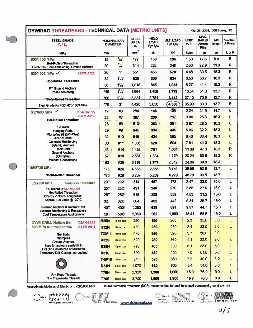
25 mm Dia Grade 517/690 Rod is good for, T = 210 kN/anchor 47.3 k /anchor
" " 830/1035 " " T = 280 kN/anchor 63.0 k /anchor
Allowable bond stress : 350 kPa ‐‐> For 65 mm Ø hole ‐‐> f_bond = 71 kN/m
Maximum hole depth 8.0 m Less the dam height = 4.34 m
Therefore, the maximum bond force, Fbond = 310 kN /anchor = 69.8 k /anchor
For Grade 517 anchors ‐‐> 3.75 anchors
For Grade 830 anchors ‐‐> 2.81 anchors
However, because sliding controls the anchor quantity required, the anchor force will reduce the crack length
and thus the uplift pressure, which will increase the friction
L:\2013\13‐033\Exstg Dwgs and Calcs\McNeil Stability v6.xlsxMcNeil Stability v6.xlsx Printed: 11/12/2013 5:12 PM
A9

BUTTRESS #2Retrofit Using Rock Anchors (cont'd)
Flood case governs anchor requirements. For that case, the forces at the foundation without uplift are:
Load FX FZ x z Mtoe
Subtotal (no Uplift) 120 ‐113 k ‐212
3 Gr 830 Anchors ‐189 k ‐1607
‐302 k ‐1819
Anchors appear to have provide enough resisting moment to eliminate base cracking
Therefore calculate uplift on that basis and verify the assumption by checking bearing pressures
From Uplift 74 2.85 526
Before: Total 120 ‐229 ‐1293 .
Resultant location: x = 4.35 ft ‐‐> e = 0.76 ft ‐‐> MCB = 173 ft‐k
Heel bearing pressure qheel = 1.07 ksf COMPRESSION
Toe bearing pressure qtoe = 4.15 ksf
Sliding Resistance Bearing Force, N = 229 k
Friction F = N∙tanф = 166 k Driving Force 120 k
Cohesion C = c∙Abrg = 0
Total 166 k Factor of Safety 1.38
REQUIRED F.S. 1.1
(3) 25 mm Diameter Grade 830 anchors provide adequate overturning and sliding resistance.
L:\2013\13‐033\Exstg Dwgs and Calcs\McNeil Stability v6.xlsxMcNeil Stability v6.xlsx Printed: 11/12/2013 5:12 PM
A10

Job No. 13-033
Vol./Sheet No. of
Contract/Client Sunshine Coast Regional District
Phase/Subject McNeil Dam
Design Topic Dam Stability Analysis
Made By CMW Date 10/15/13 Checked By MGH Date 11/11/13 Page No.
ANALYSIS OF BUTTRESS #3
12’-0”
A11

BUTTRESS #3
Material Properties
Concrete‐Rock Interface Material Densities
Friction Angle 36 deg Water 62.4 pcf
Cohesion 0 psi Concrete 150 pcf
Dam Geometry
Assume stop logs in place for all cases, meaning the crest height is essentially maintained across the spillway
Dam Cross‐Section Base Properties
Height to crest 12.67 ft Base Area Abase = 109.9 SF
Base Width: Center of Bearing xcb = 3.64 ft
Btwn Buttresses 6.06 ft Moment of Inertia Ibase = 625 ft4
At Buttresses 10.38 ft Section Moduli Sheel = 171.6 ft3
Buttress Thickness 3 ft Stoe = 92.7 ft3
Trib Length 16 ft
Weight Tributary to Buttress
Tributary Volume 814 cu ft Section CG xcg = 2.51 ft
Weight 122 k zcg = 4.90 ft
66.4"
44.2" 80.5"
62.0"
A1 = 6624 sq in = 46.0 sq ft
A2 = 12211 sq in = 84.8 sq ft
A3 = 5789 sq in = 40.2 sq ft
24.3" 100.4"
AT SPILLWAY BUTTRESS (#3): L1 = 6.5', L2 = 3.0', L3 = 6.5' --> V1 = 299 cu ft, V2 = 254 cu ft, V3 = 261 cu ft --> V = 814 cu ft
47.1"
12'-8"
10'-412"
30.1" 94.6"
58.8"
BUTTRESS #3
LENGTH: 16.0'VOLUME: 814 cu ftWEIGHT: 122 kips
L:\2013\13‐033\Exstg Dwgs and Calcs\McNeil Stability v6.xlsxMcNeil Stability v6.xlsx Printed: 11/12/2013 5:12 PM
A12

BUTTRESS #3
Usual Load Condition
Water Elevations
Headwater Elev 12.42 ft pHW = 775 psf
Tailwater Elev 0 ft pTW = 0 psf
Load Summation
Load FX FZ x z Mtoe
Dead Load ‐122 2.51 4.90 ‐961
Headwater 77 4.14 319
Tailwater 0 0.00 0
Subtotal 77 ‐122 ‐642
For uplift, start by assuming uncracked base ‐‐> ℓc = 0.00 ft
Uplift 38 2.02 314
Total 77 ‐85 ‐328
Overturning Calculation
Resultant location: x = 6.50 ft ‐‐> e = 2.86 ft ‐‐> MCB = 241 ft‐k
Heel bearing pressure qheel = ‐0.64 ksf UPLIFT
Toe bearing pressure qtoe = 3.37 ksf
Tension Zone length 1.65 ft ‐‐> Lbrg < 0.84L
Lbrg = 0.53 * L = 5.50 ft ‐‐> ℓc = 4.88 ft
qtoe = 5.45 ksf ‐‐> qa = 1.17 ksf (brg press at toe btwn buttresses)
Uplift pressure within base crack will be the full headwater pressure, therefore need to recalculate it
FZ x Mtoe
Uplift 68 2.75 518
Totals ‐54 ‐125 ‐‐> MCB = 241 ft‐k
Check for Equilibrium
Bearing Force N = 54 k <1% DIFF
Resisting Moment Mtoe = 125 ft‐k <1% DIFF
Equilibrium has base 53% in compression. CDA standards require ~100% of base in compression for Usual conditions.
Therefore this buttress does not meet the requirements without considering load sharing
Since equilibrium requires tension, which can't occur, need to iterate heel pressure and crack length to reach
equilibrium with zero tension.
CONVERGED
L:\2013\13‐033\Exstg Dwgs and Calcs\McNeil Stability v6.xlsxMcNeil Stability v6.xlsx Printed: 11/12/2013 5:12 PM
A13

BUTTRESS #3Usual Load Condition (cont'd)
The maximum moment about the center of bearing for zero force at the heel is MCB(max) = (P/A)*Sheel
MCB(max) = 132 ft‐k ‐‐> ∆MCB = 109 ft‐k
Force is applied: 11.2 ft above toe ‐‐> FREQ'D = 9.8 k
Using the the same force at Buttress #2, calculate the moment in the beam if it spans from #1 to #4
MBEAM ~ FREQ'D * 15 ft = 147 ft‐k
Beam is very lightly reinforced, therefore treat as unreinf and calc Mcr using fr = 0.1 f'c and f'c = 5 ksi
For a 3 ft x 3 ft section, Mcr = 324 ft‐k
Sliding Resistance Bearing Force, N = 54 k
Friction F = N∙tanф = 39 k Driving Force 77 k
Cohesion C = c∙Abrg = 0
Total 39 k Factor of Safety 0.51
REQUIRED F.S. 1.5
Friction angle required in the absence of cohesion
фREQ'D = 64.8 deg
Cohesion required given ф = 36°
cREQ'D = 42.1 psi (for F.S. = 2 per CDA requirements when considering cohesion
validated by testing)
However, as seen on Buttress #2, the extreme cases are considerably worse
The value of фREQ'D is larger than could be reasonably be expected to occur, and the value of cREQ'D is at the higher
end of what could be expected to be shown through testing.
Based on the results for Buttress #2, while load‐sharing may be feasible for the usual case, it is not robust
enough for the extreme cases. Calculate required force anyway for comparison purposes
This calculation is approximate, but it appears this buttress can meet the overturning requirements for the
usual case if Buttresses #1 and #4 can support the additional load.
F.S. < 1 indicates potential for sliding. However lack of distress or movement in the dam indicates that other
sources of stability are present. The most likely are, cohesion, a higher friction angle and restraint provided by
continuity across the width of the dam sharing load between buttresses.
L:\2013\13‐033\Exstg Dwgs and Calcs\McNeil Stability v6.xlsxMcNeil Stability v6.xlsx Printed: 11/12/2013 5:12 PM
A14
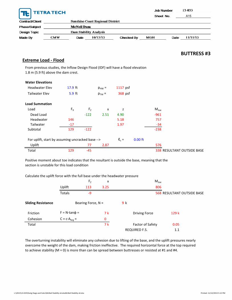
BUTTRESS #3Extreme Load ‐ Flood
Water Elevations
Headwater Elev 17.9 ft pHW = 1117 psf
Tailwater Elev 5.9 ft pTW = 368 psf
Load Summation
Load FX FZ x z Mtoe
Dead Load ‐122 2.51 4.90 ‐961
Headwater 146 5.18 757
Tailwater ‐17 1.97 ‐34
Subtotal 129 ‐122 ‐238
For uplift, start by assuming uncracked base ‐‐> ℓc = 0.00 ft
Uplift 77 2.87 576
Total 129 ‐45 338 RESULTANT OUTSIDE BASE
FZ x Mtoe
Uplift 113 3.25 806
Totals ‐9 568 RESULTANT OUTSIDE BASE
Sliding Resistance Bearing Force, N = 9 k
Friction F = N∙tanф = 7 k Driving Force 129 k
Cohesion C = c∙Abrg = 0
Total 7 k Factor of Safety 0.05
REQUIRED F.S. 1.1
From previous studies, the Inflow Design Flood (IDF) will have a flood elevation
1.8 m (5.9 ft) above the dam crest.
Positive moment about toe indicates that the resultant is outside the base, meaning that the
section is unstable for this load condition
Calculate the uplift force with the full base under the headwater pressure
The overturning instability will eliminate any cohesion due to lifting of the base, and the uplift pressures nearly
overcome the weight of the dam, making friction ineffective. The required horizontal force at the top required
to achieve stability (M = 0) is more than can be spread between buttresses or resisted at #1 and #4.
L:\2013\13‐033\Exstg Dwgs and Calcs\McNeil Stability v6.xlsxMcNeil Stability v6.xlsx Printed: 11/12/2013 5:12 PM
A15

BUTTRESS #3Extreme Load ‐ Earthquake
Water Elevations
Headwater Elev 12.42 ft pHW = 775 psf
Tailwater Elev 0 ft pTW = 0 psf
Seismic Load
Peak Ground Acceleration PGA = 0.38 g
Seismic Coefficient = ⅔PGA = 0.25 g
Load Summation
Load FX FZ x z Mtoe
Dead Load ‐122 2.51 4.90 ‐961
Headwater 77 4.14 319
Tailwater 0 0.00 0
Hydrodynamic 34 4.97 170
Struct Response 31 2.51 78
Subtotal 142 ‐122 ‐395
Therefore, use the uplift calculated for the usual condition:
Uplift (from Usual Case) 68 2.75 518
Total 142 ‐54 123 RESULTANT OUTSIDE BASE
Sliding Resistance Bearing Force, N = 54 k
Friction F = N∙tanф = 39 k Driving Force 142 k
Cohesion (Use zero for EQ) 0
Total 39 k Factor of Safety 0.28
REQUIRED F.S. 1.1
For seismic, it is assumed that the crack opening occurs over too short a time to affect uplift
For overturning, the resultant is outside the base, and thus outside the criteria. The sliding F.S is less than one,
indicating that instantaneous sliding is likely to occur during the design seismic event
The required stability criteria are not met at this buttress for both the Flood and Seismic load conditions.
Therefore some retrofit is required regardless of whether the usual case could be shown to comply.
L:\2013\13‐033\Exstg Dwgs and Calcs\McNeil Stability v6.xlsxMcNeil Stability v6.xlsx Printed: 11/12/2013 5:12 PM
A16

BUTTRESS #3Retrofit Using Rock Anchors
Forces and Moments Required to Meet Stability Requirements
Overturning Moment Required
Case Remark ∆MREQ'D
Usual See Usual Case section for calculation of ∆M 109 ft‐k about ctr of brg
Extreme Flood Resultant within base requires Mtoe = 0 568 ft‐k about toe
Extreme EQ Meets requirement as is 123 ft‐k about toe
Sliding Resistance Required
Driving Resisting Req'dCase Force Force F.S. ∆FREQ'D
Usual 77 k 39 k 1.5 76 k
Extreme Flood 129 k 7 k 1.1 135 k
Extreme EQ 142 k 39 k 1.1 117 k
Use rock anchors installed vertically through crest of dam
xanch = 1.5 ft from heel (at base) Angle from horiz, θ = 90 deg
Case ∆MREQ'D r TREQ'D ∆FREQ'D TREQ'D TMAX
Usual 109 ft‐k 2.14 ft 51 k 76.1 k 105 k 105 k
Extreme Flood 568 ft‐k 8.88 ft 64 k 135.2 k 186 k 186 k
Extreme EQ 123 ft‐k 8.88 ft 14 k 116.8 k 161 k 161 k
Minimum Anchor Force Required: 186 k = 827 kN (convert to metric for anchor calcs)
From Rock Anchor Calculations
25 mm Dia Grade 517/690 Rod is good for, T = 210 kN/anchor 47.3 k /anchor
" " 830/1035 " " T = 280 kN/anchor 63.0 k /anchor
Allowable bond stress : 350 kPa ‐‐> For 65 mm Ø hole ‐‐> f_bond = 71 kN/m
Maximum hole depth 8.0 m Less the dam height = 4.14 m
" " 830/1035 " " T = 296 kN /anchor = 66.5 k /anchor
For Grade 517 anchors ‐‐> 3.94 anchors
For Grade 830 anchors ‐‐> 2.95 anchors
However, because sliding controls the anchor quantity required, the anchor force will reduce the crack length
and thus the uplift pressure, which will increase the friction
L:\2013\13‐033\Exstg Dwgs and Calcs\McNeil Stability v6.xlsxMcNeil Stability v6.xlsx Printed: 11/12/2013 5:12 PM
A17

BUTTRESS #3Retrofit Using Rock Anchors (cont'd)
Flood case governs anchor requirements. For that case, the forces at the foundation without uplift are:
Load FX FZ x z Mtoe
Subtotal (no Uplift) 129 ‐122 k ‐238
3 Gr 830 Anchors ‐189 k ‐1678
‐311 k ‐1916
Anchors appear to have provide enough resisting moment to eliminate base cracking
Therefore calculate uplift on that basis and verify the assumption by checking bearing pressures
From Uplift 77 2.87 576
Before: Total 129 ‐234 ‐1340 .
Resultant location: x = 4.66 ft ‐‐> e = 1.02 ft ‐‐> MCB = 239 ft‐k
Heel bearing pressure qheel = 0.74 ksf COMPRESSION
Toe bearing pressure qtoe = 4.71 ksf
.
Sliding Resistance Bearing Force, N = 234 k
Friction F = N∙tanф = 170 k Driving Force 129 k
Cohesion C = c∙Abrg = 0
Total 170 k Factor of Safety 1.32
REQUIRED F.S. 1.1
(3) 25 mm Diameter Grade 830 anchors provide adequate overturning and sliding resistance.
L:\2013\13‐033\Exstg Dwgs and Calcs\McNeil Stability v6.xlsxMcNeil Stability v6.xlsx Printed: 11/12/2013 5:12 PM
A18

Job No. 13-033
Vol./Sheet No. of
Contract/Client Sunshine Coast Regional District
Phase/Subject McNeil Dam
Design Topic Dam Stability Analysis
Made By CMW Date 10/15/13 Checked By MGH Date 11/11/13 Page No.
ANALYSIS OF BUTTRESS #1 AND WING WALL
X
X
SECTION X-X (AT BUTTRESS #1)
7’-6”
BLOCK AT BASE OF
BUTTRESS EMBEDDED
IN ROCK
7’-6”
A19

BUTTRESS #1
Material Properties
Concrete‐Rock Interface Material Densities
Friction Angle 36 deg Water 62.4 pcf
Cohesion 0 psi Concrete 150 pcf
Dam Geometry
Dam Cross‐Section Base Properties
Max height to crest 7.5 ft Base Area Abase = 39.8 SF
Base Elevations Center of Bearing xcb = 2.72 ft
S of Buttress 0.0 ft Moment of Inertia Ibase = 160 ft4
At Buttress 0.0 ft Section Moduli Sheel = 58.9 ft3
N of Buttress 2.5 ft Stoe = 34.3 ft3
Base Width:
S of Buttress 3 ft Weight Tributary to Buttress
At Buttress 7.38 ft Tributary Volume 249 cu ft
N of Buttress 4.42 ft Weight 37 k
Base Length: Section CG xcg = 2.07 ft
S Trib Length 5.88 ft zcg = 3.50 ft
Buttress Thickness 3 ft
N Trib Length 0 ft Neglect Wing Wall N of buttress because of joint at face of buttress
18.0" 70.5"
45.0"
33.0" 55.5"
38.7"
A1 = 3240 sq in = 22.5 sq ft
A2 = 5602 sq in = 38.9 sq ft
AT BUTTRESS #1: L1 = 5.88', L2 = 3.0' --> V1 = 132 cu ft, V2 = 117 cu ft, --> V = 249 cu ft
7'-6"
7'-412"
24.8" 63.7"
42.0"
BUTTRESS #1
LENGTH: 8.88'VOLUME: 249 cu ftWEIGHT: 37 kips
32.6" 55.9"
A = 5724 sq in = 39.8 sq ftIy = 3326978 in4 = 160 ft4S_heel = 58.8 ft3S_toe = 34.3 ft3
7'-412"
3'-0"
L:\2013\13‐033\Exstg Dwgs and Calcs\McNeil Stability v6.xlsxMcNeil Stability v6.xlsx Printed: 11/12/2013 5:12 PM
A20

BUTTRESS #1
Usual Load Condition
Water Elevations South Buttress North
Headwater Elev 7.25 ft pHW = 452 psf 452 psf 296 psf
Tailwater Elev 0 ft pTW = 0 psf 0 psf 0 psf
Load Summation
Load FX FZ x z Mtoe
Dead Load ‐37 2.07 3.50 ‐198
Headwater 15 2.42 35
Tailwater 0 0.00 0
Subtotal 15 ‐37 ‐163
For uplift, start by assuming uncracked base ‐‐> ℓc = 0.00 ft
Uplift 9 1.81 50
Total 15 ‐28 ‐113
Overturning Calculation
Resultant location: x = 3.39 ft ‐‐> e = 0.67 ft ‐‐> MCB = 19 ft‐k
Heel bearing pressure qheel = 0.39 ksf COMPRESSION
Toe bearing pressure qtoe = 1.27 ksf
.
Buttress #1 meets overturning criteria for usual case, but lacks capacity to take excess load from adj buttress
Sliding Resistance Bearing Force, N = 28 k
dembed = 1.0 ft ‐‐> Aplane = b∙dembed/sinф = 5.10 SF (for b = 3 ft) ‐‐> Fbreakout = 26 k
Friction F = N∙tanф = 21 k Driving Force 15 k
Cohesion C = c∙Abrg = 0
Breakout 26
Total 46 k Factor of Safety 3.18
REQUIRED F.S. 1.5 OK
Buttress #1 meets sliding criteria for Usual case
The toe of this buttress is embedded about 1 foot into the rock at it's toe, therefore sliding failure requires breakout of the
rock in front of the toe. The breakout force will be equal to the internal cohesion of the rock acting on the area of the
breakout plane. Assume the angle of the plane from horizontal will be equal to the friction angle, ф, and use the value of 250 kPa (= 35 psi) from the original calculations for the effective cohesion in the rock.
L:\2013\13‐033\Exstg Dwgs and Calcs\McNeil Stability v6.xlsxMcNeil Stability v6.xlsx Printed: 11/12/2013 5:12 PM
A21

BUTTRESS #1Extreme Load ‐ Flood
Water Elevations South Buttress North
Headwater Elev 13.4 ft pHW = 836 psf 836 psf 680 psf
Tailwater Elev 5.9 ft pTW = 368 psf 368 psf 212 psf
(At base of section)
Load Summation
Load FX FZ x z Mtoe
Dead Load ‐37 2.07 3.50 ‐198
Headwater 40 3.26 131
Tailwater ‐10 1.97 ‐19
Subtotal 30 ‐37 ‐87
For uplift, start by assuming uncracked base ‐‐> ℓc = 0.00 ft
Uplift 24 2.92 107
Total 30 ‐13 20 RESULTANT OUTSIDE BASE
FZ x Mtoe
Uplift 33 2.72 155
Totals ‐4 69 RESULTANT OUTSIDE BASE
Sliding Resistance Bearing Force, N = 4 k
Friction F = N∙tanф = 3 k Driving Force 30 k
Cohesion C = c∙Abrg = 0
Breakout (See above for calc) 26 k Factor of Safety 0.94
Total 29 k REQUIRED F.S. 1.1
From previous studies, the Inflow Design Flood (IDF) will have a flood elevation
1.8 m (5.9 ft) above the dam crest.
Positive moment about toe indicates that the resultant is outside the base, meaning that the
section is unstable for this load condition and the base is fully cracked
Calculate the uplift force with the full base under the headwater pressure
L:\2013\13‐033\Exstg Dwgs and Calcs\McNeil Stability v6.xlsxMcNeil Stability v6.xlsx Printed: 11/12/2013 5:12 PM
A22

BUTTRESS #1Extreme Load ‐ Earthquake
Water Elevations South Buttress North
Headwater Elev 7.25 ft pHW = 452 psf 452 psf 296 psf
Tailwater Elev 0 ft pTW = 0 psf 0 psf 0 psf
(At base of section)
Seismic Load
Peak Ground Acceleration PGA = 0.38 g
Seismic Coefficient = ⅔PGA = 0.25 g
Load Summation
Load FX FZ x z Mtoe
Dead Load ‐37 2.07 3.50 ‐198
Headwater 15 2.42 35
Tailwater 0 0.00 0
Hydrodynamic 4 2.90 12
Struct Response 9 3.50 33
Subtotal 28 ‐37 ‐118
Therefore, use the uplift calculated for the usual condition:
Uplift 9 1.30 55
Total 28 ‐28 ‐63 RESULTANT INSIDE BASE
Resultant is within base, therefore overturning criterion is met
Sliding Resistance Bearing Force, N = 28 k
Friction F = N∙tanф = 21 k Driving Force 28 k
Cohesion (Use zero for EQ) 0
Breakout (See above for calc) 26 Factor of Safety 1.64
Total 46 k REQUIRED F.S. 1.1 OK
For seismic, it is assumed that the crack opening occurs over too short a time to affect uplift
L:\2013\13‐033\Exstg Dwgs and Calcs\McNeil Stability v6.xlsxMcNeil Stability v6.xlsx Printed: 11/12/2013 5:12 PM
A23

BUTTRESS #1Retrofit Using Rock Anchors
Forces and Moments Required to Meet Stability Requirements
Overturning Moment Required
Case Remark ∆MREQ'D
Usual See Usual Case section for calculation of ∆M 0 ft‐k about ctr of brg
Extreme Flood Resultant within base requires Mtoe = 0 69 ft‐k about toe
Extreme EQ Meets requirement as is 0 ft‐k about toe
Sliding Resistance Required
Driving Resisting Req'd
Case Force Force F.S. ∆FREQ'D
Usual 15 k 46 k 1.5 0.0 k
Extreme Flood 30 k 29 k 1.1 4.8 k
Extreme EQ 28 k 46 k 1.1 0.0 k
Use rock anchors installed vertically through crest of dam
xanch = 1.5 ft from heel (at base) Angle from horiz, θ = 90 deg
Case ∆MREQ'D r TREQ'D ∆FREQ'D TREQ'D TMAX
Usual 0 ft‐k 1.22 ft 0 k 0.0 k 0 k 0 k
Extreme Flood 69 ft‐k 5.88 ft 12 k 4.8 k 7 k 12 k
Extreme EQ 0 ft‐k 5.88 ft 0 k 0.0 k 0 k 0 k
Minimum Anchor Force Required: 12 k = 52 kN (convert to metric for anchor calcs)
From Rock Anchor Calculations
25 mm Dia Grade 517/690 Rod is good for, T = 210 kN/anchor 47.3 k /anchor
" " 830/1035 " " T = 280 kN/anchor 63.0 k /anchor
Allowable bond stress : 350 kPa ‐‐> For 65 mm Ø hole ‐‐> f_bond = 71 kN/m
Maximum hole depth 8.0 m Less the dam height = 5.71 m
Therefore, the maximum bond force, Fbond = 408 kN /anchor = 91.9 k /anchor
For Grade 517 anchors ‐‐> 0.25 anchors
For Grade 830 anchors ‐‐> 0.18 anchors
(1) 25 mm Diameter Grade 830 anchor provides adequate overturning and sliding resistance.
L:\2013\13‐033\Exstg Dwgs and Calcs\McNeil Stability v6.xlsxMcNeil Stability v6.xlsx Printed: 11/12/2013 5:12 PM
A24

ANALYSIS FOR 20 FT OF WING WALL ADJACENT TO BUTTRESS #1
Material Properties
Concrete‐Rock Interface Material Densities
Friction Angle 36 deg Water 62.4 pcf
Cohesion 0 psi Concrete 150 pcf
Dam Geometry
Dam Cross‐Section Base Properties
Height to crest (Avg) 4.3 ft Base Area Abase = 79.6 SF
Base Width (Avg): 3.98 ft Center of Bearing xcb = 1.99 ft
Length considered: 20 ft Moment of Inertia Ibase = 105 ft4
Section Moduli Sheel = 52.8 ft3
Stoe = 52.8 ft3
Weight Tributary to Buttress
Tributary Volume 233 cu ft Section CG xcg = 1.46 ft
Weight 35 k zcg = 1.80 ft
L:\2013\13‐033\Exstg Dwgs and Calcs\McNeil Stability v6.xlsxMcNeil Stability v6.xlsx Printed: 11/12/2013 5:27 PM
A25

WING WALL ADJ TO BUTTRESS #1
Usual Load Condition
Water Elevations
Headwater Elev 4.00 ft pHW = 250 psf
Tailwater Elev 0 ft pTW = 0 psf
Load Summation
Load FX FZ x z Mtoe
Dead Load ‐35 1.46 1.80 ‐88
Headwater 10 1.33 13
Tailwater 0 0.00 0
Subtotal 10 ‐35 ‐75
For uplift, start by assuming uncracked base ‐‐> ℓc = 0.00 ft
Uplift 10 1.33 26
Total 10 ‐25 ‐48 RESULTANT INSIDE BASE
Overturning Calculation
Resultant location: x = 2.05 ft ‐‐> e = 0.06 ft ‐‐> MCB = 1.5 ft‐k
Heel bearing pressure qheel = 0.29 ksf COMPRESSION
Toe bearing pressure qtoe = 0.34 ksf
.
Sliding Resistance Bearing Force, N = 25 k
Friction F = N∙tanф = 18 k Driving Force 10 k
Cohesion C = c∙Abrg = 0
Total 18 k Factor of Safety 1.82
REQUIRED F.S. 1.5
The wing wall meets the stability criteria for the usual case
L:\2013\13‐033\Exstg Dwgs and Calcs\McNeil Stability v6.xlsxMcNeil Stability v6.xlsx Printed: 11/12/2013 5:27 PM
A26

WING WALL ADJ TO BUTTRESS #1Extreme Load ‐ Flood
Water Elevations
Headwater Elev 10.2 ft pHW = 633 psf
Tailwater Elev 4.3 ft pTW = 265 psf
Load Summation
Load FX FZ x z Mtoe
Dead Load ‐35 1.46 1.80 ‐88
Headwater 43 1.94 82
Tailwater ‐11 1.42 ‐16
Subtotal 31 ‐35 ‐21
For uplift, start by assuming uncracked base ‐‐> ℓc = 0.00 ft
Uplift 36 1.72 81
Total 31 1 59 RESULTANT OUTSIDE BASE
FZ x Mtoe
Uplift 50 1.99 100
Totals 15 79 RESULTANT OUTSIDE BASE
Sliding Resistance Bearing Force, N = 0 k
Friction F = N∙tanф = 0 k Driving Force 31 k
Cohesion C = c∙Abrg = 0
Total 0 k Factor of Safety 0.00
REQUIRED F.S. 1.1
The overturning instability will eliminate any cohesion due to lifting of the base, and the uplift pressures
overcome the weight of the wall, making friction ineffective.
From previous studies, the Inflow Design Flood (IDF) will have a flood elevation
1.8 m (5.9 ft) above the dam crest.
Positive moment about the toe indicates that the resultant is outside the base, meaning the overturning criterion
is not met for this case, and the base would be fully cracked.
Calculate the uplift force with the full base under the headwater pressure
L:\2013\13‐033\Exstg Dwgs and Calcs\McNeil Stability v6.xlsxMcNeil Stability v6.xlsx Printed: 11/12/2013 5:27 PM
A27

WING WALL ADJ TO BUTTRESS #1Extreme Load ‐ Earthquake
Water Elevations
Headwater Elev 4 ft pHW = 250 psf
Tailwater Elev 0 ft pTW = 0 psf
Seismic Load
Peak Ground Acceleration PGA = 0.38 g
Seismic Coefficient = ⅔PGA = 0.25 g
Load Summation
Load FX FZ x z Mtoe
Dead Load ‐35 1.46 1.80 ‐88
Headwater 10 1.33 13
Tailwater 0 0.00 0
Hydrodynamic 3 1.60 5
Struct Response 9 1.80 16
Subtotal 22 ‐35 ‐54
Therefore, use the uplift calculated for the usual condition:
Uplift 10 1.33 26
Total 22 ‐25 ‐28 RESULTANT INSIDE BASE
The resultant is within the base, which meets the overturning criterion.
Sliding Resistance Bearing Force, N = 25 k
Friction F = N∙tanф = 18 k Driving Force 22 k
Cohesion (Use zero for EQ) 0
Total 18 k Factor of Safety 0.83
REQUIRED F.S. 1.1
Thr sliding factor of safety is less than one which indicates that instantaneous movement may occur.
For seismic, it is assumed that the crack opening occurs over too short a time to affect uplift
L:\2013\13‐033\Exstg Dwgs and Calcs\McNeil Stability v6.xlsxMcNeil Stability v6.xlsx Printed: 11/12/2013 5:27 PM
A28

WING WALL ADJ TO BUTTRESS #1Retrofit Using Rock Anchors
Forces and Moments Required to Meet Stability Requirements
Overturning Moment Required
Case Remark ∆MREQ'D
Usual Meets requirement as is 0 ft‐k about ctr of brg
Extreme Flood Resultant within base requires Mtoe = 0 79 ft‐k about toe
Extreme EQ Meets requirement as is 0 ft‐k about toe
Sliding Resistance Required
Driving Resisting Req'dCase Force Force F.S. ∆FREQ'D
Usual 10 k 18 k 1.5 0.0 k
Extreme Flood 31 k 0 k 1.1 34.4 k
Extreme EQ 22 k 18 k 1.1 5.8 k
Use rock anchors installed vertically through crest of dam
xanch = 1.0 ft from heel (at base) Angle from horiz, θ = 90 deg
Case ∆MREQ'D r TREQ'D ∆FREQ'D TREQ'D TMAX
Usual 0 ft‐k 0.99 ft 0 k 0.0 k 0 k 0 k
Extreme Flood 79 ft‐k 2.98 ft 26 k 34.4 k 47 k 47 k
Extreme EQ 0 ft‐k 2.98 ft 0 k 5.8 k 8 k 8 k
Minimum Anchor Force Required: 47 k = 211 kN (convert to metric for anchor calcs)
From Rock Anchor Calculations
25 mm Dia Grade 517/690 Rod is good for, T = 210 kN/anchor 47.3 k /anchor
" " 830/1035 " " T = 280 kN/anchor 63.0 k /anchor
Allowable bond stress : 350 kPa ‐‐> For 65 mm Ø hole ‐‐> f_bond = 71 kN/m
Maximum hole depth 8.0 m Less the dam height = 6.70 m
Therefore, the maximum bond force, Fbond = 479 kN /anchor = 107.8 k /anchor
For Grade 517 anchors ‐‐> 1.00 anchors
For Grade 830 anchors ‐‐> 0.75 anchors
(1) 25 mm Diameter Grade 830 anchor provides adequate overturning and sliding resistance.
However, given the length of wall, provide one anchor at each end.
L:\2013\13‐033\Exstg Dwgs and Calcs\McNeil Stability v6.xlsxMcNeil Stability v6.xlsx Printed: 11/12/2013 5:27 PM
A29

Job No. 13-033
Vol./Sheet No. of
Contract/Client Sunshine Coast Regional District
Phase/Subject McNeil Dam
Design Topic Dam Stability Analysis
Made By CMW Date 10/15/13 Checked By MGH Date 11/11/13 Page No.
ANALYSIS OF BUTTRESS #4
A30

BUTTRESS #4
Material Properties
Concrete‐Rock Interface Material Densities
Friction Angle 36 deg Water 62.4 pcf
Cohesion 0 psi Concrete 150 pcf
Dam Geometry
Dam Cross‐Section Base Properties
Max height to crest 12.7 ft Base Area Abase = 82.4 SF
Base Elevations Center of Bearing xcb = 3.42 ft
S of Buttress 5.0 ft Moment of Inertia Ibase = 368 ft4
At Buttress 2.0 ft Section Moduli Sheel = 107.7 ft3
N of Buttress 0.0 ft Stoe = 69.5 ft3
Base Width:
S of Buttress 2.64 ft Weight Tributary to Buttress
At Buttress 8.71 ft Tributary Volume 525 cu ft
N of Buttress 6.06 ft Weight 79 k
Base Length: Section CG xcg = 2.48 ft
S Trib Length 3 ft zcg = 5.43 ft
Buttress Thickness 3 ft
N Trib Length 6.5 ft
24.3" 49.7"
47.1"
39.6" 65.1"
77.3"
22.9" 41.8"
104.5"
AT BUTTRESS #4: L1 = 6.5', L2 = 3.0', L3 =3.0' --> V1 = 261 cu ft, V2 = 195 cu ft, V3 = 69 cu ft -->V = 525 cu ft
A1 = 5790 sq in = 40.2 sq ft
A2 = 9356 sq in = 65.0 sq ft
A3 =3307 sq in = 23.0 sq ft
12'-8"
8'-812"
29.8" 74.9"
65.1"
41.0" 63.7"
A = 11868 sq in = 82.4 sq ftIy = 7636289 in4 = 368 ft4S_heel = 107.7 ft3S_toe = 69.3 ft3
BUTTRESS #4
LENGTH: 12.5'VOLUME: 525 cu ftWEIGHT: 79 kips
L:\2013\13‐033\Exstg Dwgs and Calcs\McNeil Stability v6.xlsxMcNeil Stability v6.xlsx Printed: 11/12/2013 5:12 PM
A31

BUTTRESS #4
Usual Load Condition
Water Elevations South Buttress North
Headwater Elev 12.42 ft pHW = 463 psf 650 psf 775 psf
Tailwater Elev 0 ft pTW = 0 psf 0 psf 0 psf
Load Summation
Load FX FZ x z Mtoe
Dead Load ‐79 2.48 5.43 ‐490
Headwater 47 4.80 224
Tailwater 0 0.00 0
Subtotal 47 ‐79 ‐267
For uplift, start by assuming uncracked base ‐‐> ℓc = 0.00 ft
Uplift 26 2.23 166
Total 47 ‐53 ‐101
Overturning Calculation
Resultant location: x = 6.81 ft ‐‐> e = 3.40 ft ‐‐> MCB = 180 ft‐k
Heel bearing pressure qheel = ‐1.03 ksf UPLIFT
Toe bearing pressure qtoe = 3.24 ksf
Tension Zone length 2.10 ft ‐‐> Lbrg < 0.76L
Since equilibrium requires tension, which can't occur, need to iterate heel pressure and crack length to reach equilibrium
Lbrg = 0.01 * L = 0.09 ft ‐‐> ℓc = 8.62 ft
qtoe = 6.00 ksf ‐‐> qaS = 0.00 ksf (brg press at toe S of buttress)
qaN = 0.00 ksf (brg press at toe N of buttress)
Uplift pressure within base crack will be the full headwater pressure, therefore need to recalculate it
FZ x Mtoe
Uplift 51 3.34 274
Totals ‐28 8 ‐‐> MCB = 154 ft‐k
Check for Equilibrium
Bearing Force N = 1 k INCR
Resisting Moment Mtoe = 0 ft‐k DECR
The equations do not converge with the resultant within the base (i.e with Mtoe < 0). Therefore, the resultant is
outside the base, and the dam does not meet the criterion.
NOT CONVERGED
L:\2013\13‐033\Exstg Dwgs and Calcs\McNeil Stability v6.xlsxMcNeil Stability v6.xlsx Printed: 11/12/2013 5:12 PM
A32

BUTTRESS #4Usual Load Condition (cont'd)
Sliding Resistance Bearing Force, N = 28 k
dembed = 2.0 ft ‐‐> Aplane = b∙dembed/sinф = 10.2 SF (for b = 3 ft) ‐‐> Fbreakout = 51 k
Friction F = N∙tanф = 20 k Driving Force 47 k
Cohesion C = c∙Abrg = 0
Breakout 51
Total 72 k Factor of Safety 1.54
REQUIRED F.S. 1.5 OK
Buttress #4 meets sliding criteria for Usual case
The toe of this buttress is embedded about about 2 feet into the rock at it's toe, therefore sliding failure requires breakout
of the rock in front of the toe. The breakout force will be equal to the internal cohesion of the rock acting on the area of
the breakout plane. Assume the angle of the plane from horizontal will be equal to the friction angle, ф, and use the value of 250 kPa (= 35 psi) from the original calculations for the effective cohesion in the rock.
L:\2013\13‐033\Exstg Dwgs and Calcs\McNeil Stability v6.xlsxMcNeil Stability v6.xlsx Printed: 11/12/2013 5:12 PM
A33

BUTTRESS #4Extreme Load ‐ Flood
Water Elevations South Buttress North
Headwater Elev 18.6 ft pHW = 847 psf 1034 psf 1159 psf
Tailwater Elev 5.9 ft pTW = 56 psf 243 psf 368 psf
(At base of section)
Load Summation
Load FX FZ x z Mtoe
Dead Load ‐79 2.48 5.43 ‐490
Headwater 99 5.96 592
Tailwater ‐9 2.22 ‐19
Subtotal 91 ‐79 82
For uplift, start by assuming uncracked base ‐‐> ℓc = 0.00 ft
Uplift 50 3.19 278
Total 91 ‐28 360 RESULTANT OUTSIDE BASE
FZ x Mtoe
Uplift 79 3.34 426
Totals 1 509 RESULTANT OUTSIDE BASE
Sliding Resistance Bearing Force, N = 0 k
Friction F = N∙tanф = 0 k Driving Force 91 k
Cohesion C = c∙Abrg = 0
Breakout (See above for calc) 51 k Factor of Safety 0.57
Total 51 k REQUIRED F.S. 1.1
For the Flood Case, Buttress #4 does not meet the overturning or sliding criteria.
(note that the sliding resistance is very conservative)
From previous studies, the Inflow Design Flood (IDF) will have a flood elevation
1.8 m (5.9 ft) above the dam crest.
Positive moment about toe indicates that the resultant is outside the base, meaning that the
section is unstable for this load condition and the base is fully cracked
Calculate the uplift force with the full base under the headwater pressure
L:\2013\13‐033\Exstg Dwgs and Calcs\McNeil Stability v6.xlsxMcNeil Stability v6.xlsx Printed: 11/12/2013 5:12 PM
A34

BUTTRESS #4Extreme Load ‐ Earthquake
Water Elevations South Buttress North
Headwater Elev 12.42 ft pHW = 463 psf 650 psf 775 psf
Tailwater Elev 0 ft pTW = 0 psf 0 psf 0 psf
(At base of section)
Seismic Load
Peak Ground Acceleration PGA = 0.38 g
Seismic Coefficient = ⅔PGA = 0.25 g
Load Summation
Load FX FZ x z Mtoe
Dead Load ‐79 2.48 5.43 ‐490
Headwater 47 4.80 224
Tailwater 0 0.00 0
Hydrodynamic 14 4.97 68
Struct Response 20 5.43 108
Subtotal 80 ‐79 ‐90
Therefore, use the uplift calculated for the usual condition:
Uplift 51 3.34 274
Total 80 ‐28 184 RESULTANT OUTSIDE BASE
Resultant is outside the base
Sliding Resistance Bearing Force, N = 28 k
Friction F = N∙tanф = 20 k Driving Force 80 k
Cohesion (Use zero for EQ) 0
Breakout (See above for calc) 51 Factor of Safety 0.89
Total 72 k REQUIRED F.S. 1.1 OK
Buttress #4 has a F.S. against sliding of less than one.
For seismic, it is assumed that the crack opening occurs over too short a time to affect uplift
L:\2013\13‐033\Exstg Dwgs and Calcs\McNeil Stability v6.xlsxMcNeil Stability v6.xlsx Printed: 11/12/2013 5:12 PM
A35
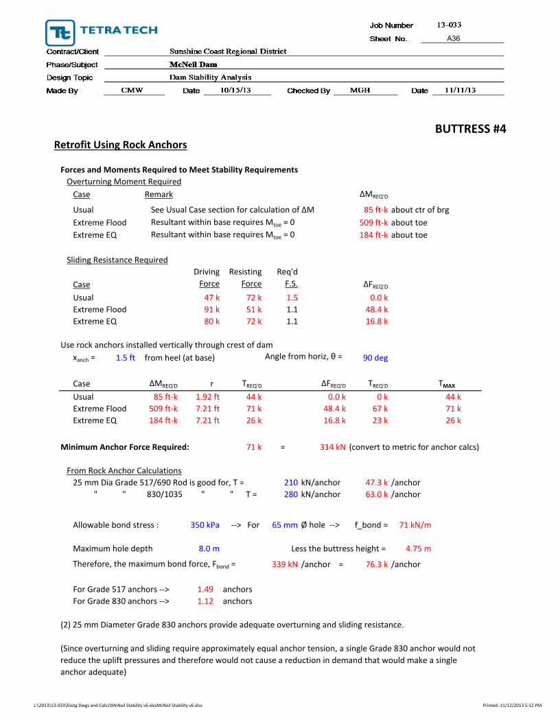
BUTTRESS #4Retrofit Using Rock Anchors
Forces and Moments Required to Meet Stability Requirements
Overturning Moment Required
Case Remark ∆MREQ'D
Usual See Usual Case section for calculation of ∆M 85 ft‐k about ctr of brg
Extreme Flood Resultant within base requires Mtoe = 0 509 ft‐k about toe
Extreme EQ Resultant within base requires Mtoe = 0 184 ft‐k about toe
Sliding Resistance Required
Driving Resisting Req'd
Case Force Force F.S. ∆FREQ'D
Usual 47 k 72 k 1.5 0.0 k
Extreme Flood 91 k 51 k 1.1 48.4 k
Extreme EQ 80 k 72 k 1.1 16.8 k
Use rock anchors installed vertically through crest of dam
xanch = 1.5 ft from heel (at base) Angle from horiz, θ = 90 deg
Case ∆MREQ'D r TREQ'D ∆FREQ'D TREQ'D TMAX
Usual 85 ft‐k 1.92 ft 44 k 0.0 k 0 k 44 k
Extreme Flood 509 ft‐k 7.21 ft 71 k 48.4 k 67 k 71 k
Extreme EQ 184 ft‐k 7.21 ft 26 k 16.8 k 23 k 26 k
Minimum Anchor Force Required: 71 k = 314 kN (convert to metric for anchor calcs)
From Rock Anchor Calculations
25 mm Dia Grade 517/690 Rod is good for, T = 210 kN/anchor 47.3 k /anchor
" " 830/1035 " " T = 280 kN/anchor 63.0 k /anchor
Allowable bond stress : 350 kPa ‐‐> For 65 mm Ø hole ‐‐> f_bond = 71 kN/m
Maximum hole depth 8.0 m Less the buttress height = 4.75 m
Therefore, the maximum bond force, Fbond = 339 kN /anchor = 76.3 k /anchor
For Grade 517 anchors ‐‐> 1.49 anchors
For Grade 830 anchors ‐‐> 1.12 anchors
(2) 25 mm Diameter Grade 830 anchors provide adequate overturning and sliding resistance.
(Since overturning and sliding require approximately equal anchor tension, a single Grade 830 anchor would not
reduce the uplift pressures and therefore would not cause a reduction in demand that would make a single
anchor adequate)
L:\2013\13‐033\Exstg Dwgs and Calcs\McNeil Stability v6.xlsxMcNeil Stability v6.xlsx Printed: 11/12/2013 5:12 PM
A36

Job No. 13-033
Vol./Sheet No. of
Contract/Client Sunshine Coast Regional District
Phase/Subject McNeil Dam
Design Topic Dam Stability Analysis
Made By CMW Date 10/15/13 Checked By MGH Date 11/11/13 Page No.
CONCLUSIONS
All of the analyzed sections do not meet the required factors of safety for sliding and overturning for at least the extreme flood (Inflow Design Flood) case. The margin of this failure is large, indicating that a more refined flood analysis that took into account overflow of the surrounding topography during the design event would not reduce the overtopping by an amount that would make retrofit unnecessary.
Therefore, calculations for the quantity of rock bolts required to reach stability were done for each of the sections assuming 25-mm diameter Grade 830 rock bolts grouted in 65 mm diameter holes with a maximum hole depth of 8 meters. The following quantities were determined:
Location Quantity Req’d
Buttress #1 1 Buttress #2 3 Buttress #3 3 Buttress #4 2 Wing Wall 2
Total 9
A37


MCNEIL LAKE DAM STABILITY ANALYSIS
NOVEMBER 2013 | ISSUED FOR USE
APPENDIX B GEOTECHNICAL CALCULATIONS


MCNEIL LAKE DAM STABILITY ANALYSIS
NOVEMBER 2013 | ISSUED FOR USE
APPENDIX C SEISMIC GROUND ACCELERATIONS


2010 National Building Code Seismic Hazard CalculationINFORMATION: Eastern Canada English (613) 995-5548 francais (613) 995-0600 Facsimile (613) 992-8836
Western Canada English (250) 363-6500 Facsimile (250) 363-6565
Requested by: ,
Site Coordinates: 49.6 North 123.99 West
User File Reference:
November 04, 2013
National Building Code ground motions:2% probability of exceedance in 50 years (0.000404 per annum)Sa(0.2) Sa(0.5) Sa(1.0) Sa(2.0) PGA (g)
Ground motions for other probabilities:Probability of exceedance per annumProbability of exceedance in 50 yearsSa(0.2)Sa(0.5)Sa(1.0)Sa(2.0)PGA
0.01040%
0.002110%
0.0015%
0.794 0.565 0.311 0.165 0.378
0.1940.1340.0710.0370.098
0.4140.2900.1570.0820.203
0.5640.3970.2160.1140.273
Notes. Spectral and peak hazard values are determined for firm ground (NBCC 2010 soil class C - averageshear wave velocity 360-750 m/s). Median (50th percentile) values are given in units of g. 5% dampedspectral acceleration (Sa(T), where T is the period in seconds) and peak ground acceleration (PGA) valuesare tabulated. Only 2 significant figures are to be used. These values have been interpolated from a 10km spaced grid of points. Depending on the gradient of the nearby points, values at this locationcalculated directly from the hazard program may vary. More than 95 percent of interpolated valuesare within 2 percent of the calculated values. Warning: You are in a region which considers the hazardfrom a deterministic Cascadia subduction event for the National Building Code. Values determined for highprobabilities (0.01 per annum) in this region do not consider the hazard from this type of earthquake.
References
National Building Code of Canada 2010 NRCCno. 53301; sections 4.1.8, 9.20.1.2, 9.23.10.2,9.31.6.2, and 6.2.1.3Appendix C: Climatic Information for BuildingDesign in Canada - table in Appendix C starting onpage C-11 of Division B, volume 2
U s e r ’ s G u i d e - N B C 2 0 1 0 , S t r u c t u r a lCommentaries NRCC no. 53543 (in preparation)Commentary J: Design for Seismic Effects
Geological Survey of Canada Open File xxxxFourth generation seismic hazard maps of Canada:Maps and grid values to be used with the 2010National Building Code of Canada (in preparation)
See the websites www.EarthquakesCanada.ca andwww.nationalcodes.ca for more information
Aussi disponible en francais 124.5˚W 124˚W 123.5˚W
49.5˚N
50˚N
0 10 20 30
km