![MCCBs: DPX TM - Electroshops.roelectroshops.ro/blog/wp-content/uploads/2014/02/Disjunctoare-DPX-L... · TM] MCCBs: DPX TM The compact range of ... Type of MCCB E Ultimate breaking](https://static.fdocuments.in/doc/165x107/5adc8ef37f8b9ae1408bb720/mccbs-dpx-tm-mccbs-dpx-tm-the-compact-range-of-type-of-mccb-e-ultimate-breaking.jpg)
MCCBs for power distribution up to...
13
A-2-65 MCCBs for power distribution up to 1600A Electrical characteristics TS1000 TS1250 TS1600 Type TS1000 TS1250 TS1600 Ampere frame 1000 1250 1600 Pole 3, 4 3, 4 3, 4 Rated current,(A) In -5~40°C 800, 1000 1250 1600 50°C 800, 1000 1250 1560 65°C 800, 1000 1240 1420 Rated insulation voltage, (V) Ui 1000 1000 1000 Rated impulse withstand voltage, (kV) Uimp 8 8 8 Rated operational voltage, (V) Ue AC50/60Hz 690 690 690 DC - - - Rated short-circuit breaking capacity N H L N H N H IEC60947-2 Rated ultimate short-circuit 220/240V 55 75 200 55 75 55 75 AC50/60Hz breaking capacity, (kA) (Icu) 380/415V 50 70 150 50 70 50 70 (sym) 440/460V 50 65 130 50 65 50 65 480/500V 40 50 100 40 50 40 50 660/690V 35 45 50 35 45 35 45 DC 250V 2P - - - - - - - 500V 2P - - - - - - - 750V 3P - - - - - - - Rated service %Icu 100% 75% 100% 100% 75% 100% 75% breaking capacity (Ics) Rated short-circuit AC50/60Hz 1s 25 12 25 25 making capacity (kA) (Icw) 3s - - - Overriding instantaneous protection kA peak 50 30 50 50 Isolation ○ ○ ○ Category B A B B Mechanical life (operations) 10000 4000 10000 10000 (Life cycle) Electrical life 440V In/2 6000 4000 5000 5000 (operations) In 5000 3000 4000 2000 690V In/2 4000 3000 3000 2000 In 2000 2000 2000 1000 Pollution degree 3 3 3 Dimension (mm) 3-pole 327×210×152.5 (H×W×D) 4-pole 327×280×152.5 Weight (kg) 3-pole 13 4-pole 16.8
Transcript of MCCBs for power distribution up to...

A-2-65
MCCBs for power distribution up to 1600A
Electrical characteristics
TS1000 TS1250 TS1600 Type TS1000 TS1250 TS1600
Ampere frame 1000 1250 1600
Pole 3, 4 3, 4 3, 4
Rated current,(A) In -5~40°C 800, 1000 1250 1600
50°C 800, 1000 1250 1560
65°C 800, 1000 1240 1420
Rated insulation voltage, (V) Ui 1000 1000 1000
Rated impulse withstand voltage, (kV) Uimp 8 8 8
Rated operational voltage, (V) Ue AC50/60Hz 690 690 690
DC - - -
Rated short-circuit breaking capacity N H L N H N H
IEC60947-2 Rated ultimate short-circuit 220/240V 55 75 200 55 75 55 75
AC50/60Hz breaking capacity, (kA) (Icu) 380/415V 50 70 150 50 70 50 70
(sym) 440/460V 50 65 130 50 65 50 65
480/500V 40 50 100 40 50 40 50
660/690V 35 45 50 35 45 35 45
DC 250V 2P - - - - - - -
500V 2P - - - - - - -
750V 3P - - - - - - -
Rated service %Icu100% 75% 100% 100% 75% 100% 75%
breaking capacity (Ics)
Rated short-circuit AC50/60Hz 1s 25 12 25 25
making capacity (kA) (Icw) 3s - - -
Overriding instantaneous protection kA peak 50 30 50 50
Isolation ○ ○ ○
Category B A B B
Mechanical life (operations) 10000 4000 10000 10000
(Life cycle) Electrical life 440V In/2 6000 4000 5000 5000
(operations) In 5000 3000 4000 2000
690V In/2 4000 3000 3000 2000
In 2000 2000 2000 1000
Pollution degree 3 3 3
Dimension (mm) 3-pole 327×210×152.5
(H×W×D) 4-pole 327×280×152.5
Weight (kg) 3-pole 13
4-pole 16.8

A-2-66
MCCBs for power distribution up to 1600A
Classification N type A type P type S type
Externals
Current �L / S / I / G / Thermal �L / S / I / G / Thermal �L / S / I / G / Thermal(Continuous) �P typeprotection �ZSI(Protective coordination) �ZSI(Protective coordination)
� Earth leakage (Option) �Earth leakage(Option) �P type
Other�Over/Under current
protection�Over/Under frequency�Unbalance(Voltage/Current)�Reverse power
�Current (R / S / T / N) �3 Phase Voltage/Current �3 Phase Voltage/CurrentRMS/Vector RMS/Vector
�Power(P, Q, S), PF(3-Phase) �Power(P, Q, S), PF(3-Phase)�Energy(Positive/Negative) �Energy(Positive/Negative)
Measurement �Frequency, Demand �Frequency, Demandfunction �Voltage/Current harmonics
(1st~63th)�3 Phase Waveforms�THD, TDD, K-Factor
Fine adjustment�Fine adjustment for long/short �P type
time delay/instantaneous/ ground�Overload protection relays �P type
Pre Trip Alarm: DO (Alarm)(Ground fault is not available when using Pre trip alarm)
Digital Output�3DO (Fixed) �3DO (Programmable) �P type�L, S/I, G Alarm �Trip, Alarm, General
IDMTL setting�Compliance with IEC60255-3 �P type
SIT, VIT, EIT, DT
Communication�Modbus/RS-485 �Modbus / RS-485 �Modbus / RS-485�Profibus-DP �Profibus-DP �Profibus-DP
�Self Power �Self Power �AC/DC 100~250V �AC/DC 100~250V-Power source - Power source works over �DC 24~60V �DC 24~60Vworks over 25% of 25% of current of In (one pole)
Power supply current of In (one pole) - External power source arerequired for comm.
�AC/DC 100~250V�DC 24~60V
RTC timer �Available �Available �Available �Available
LED for�Long time delay �N type �N type �N type
trip info.�Short time delay/Instantaneous�Ground fault
�10 records �256 records �256 records Fault recording
(Fault/Current/Date and Time) (Fault/Current/Date and Time) �Last fault wave recording (3 Phase)Event recording �256 records(Content, Status, Date) �P type
Operating �Reset button �Reset, Menu �A type �A typebutton Up/Down, Left/Right, Enter
Basic protection function(L / S / I / G)is still under normal operation
without control power.
-
-
-
-
-
-
-
--
-
-
-
Overview

A-2-67
MCCBs for power distribution up to 1600A
① LED: Indication of trip info. and overload state
Ig: LED indicating ground-faultIsd/Ii: LED indicating short-time or instantaneous trippingIr: LED indicating long-time delaySP: Self-protection and battery test LEDAlarm: LED indicating an overload
(Turn on above 90%, Blink above 105%)
② Reset Key: Fault reset or battery check
③ Iu, Ir: Long-time current setting, tr: Long-time tripping delay setting
④ Isd: Short-time current setting, tsd: Short-time tripping delay setting
⑤ Ii: Instantaneous current setting
⑥ Ig: Ground fault current setting, tg: Ground fault tripping delay setting
⑦ Test terminal: OCR test terminal (Connected with OCR tester)
Alarm SP IrIsdIi Ig
⑦
⑤
②①
③
④
⑥
N type: ��Normal��type
■ Optimized protection function■ OCR, OCGR function according IEC60947-2■ Overload protection
-Long-time delay-Thermal
■ Short-circuit protection-Short-time delay / Instantaneous-I2t On/Off optional (for short-time delay)
■ Ground fault protection-I2t On/Off optional
■ Self-Power

MCCBs for power distribution up to 1600A
A-2-68
t
Ir
tr
I
lsd
Ii
tsd
t
Ig
I
tg
Protection
NV type (For ship only)
Long timeCurrent setting (A) Iu = In×... 0.5 0.6 0.7 0.8 0.9 1.0
Ir = Iu×... 0.8 0.83 0.85 0.88 0.9 0.93 0.95 0.98 1.0Time delay (s) tr@(1.5×lr) 12.5 25 50 100 200 300 400 500 OffAccuracy: ±15% or below tr@(6.0×lr) 0.5 1 2 4 8 12 16 20 Off100ms tr@(7.2×lr) 0.34 0.69 1.38 2.7 5.5 8.3 11 13.8 Off
Short timeCurrent setting (A)
Isd = Ir×... 1.5 2 3 4 5 6 8 10 OffAccuracy: ±10%Time delay (s)
tsdI2t Off 0.05 0.1 0.2 0.3 0.4
@ 10×Ir I2t On 0.1 0.2 0.3 0.4Min. Trip
20 80 160 260 360(I2t Off)
Time(ms)Max. Trip
80 140 240 340 440Time(ms)
InstantaneousCurrent setting (A) Ii = In×... 2 3 4 6 8 10 12 15 OffTripping time 50(±10ms)
Ground faultPick-up (A)Accuracy: ±10%(Ig�0.4In) Ig = In×... 0.2 0.3 0.4 0.5 0.6 0.7 0.8 1.0 Off
±20%(Ig≤0.4In)
tgI2t Off 0.05 0.1 0.2 0.3 0.4I2t On 0.1 0.2 0.3 0.4
Time delay (s) Min. Trip20 80 160 260 360
@ 1×In(I2t Off)
Time(ms)Max. Trip
80 140 240 340 440Time(ms)
ProtectionLong time
Current setting (A) Ir = In×... 0.8 0.9 1.0 1.05 1.1 1.15 1.2 1.25 OffTime delay (s) tr@(1.2×Ir) 10 15 20 25 30 40 50 60 100Accuracy: ±15% or below tr@(3×Ir) 0.99 1.49 1.99 2.48 2.98 3.97 4.97 5.96 9.93100ms tr@(6×Ir) 0.24 0.36 0.48 0.59 0.71 0.95 1.19 1.43 2.38Short timeCurrent setting (A)
Isd = In×... 2 2.5 2.7 3 3.5 4 4.5 5 OffAccuracy: ±10%Time delay (s)
tsdI2t Off 0.05 0.1 0.2 0.3 0.4
@ 10×Ir I2t On 0.1 0.2 0.3 0.4Min. Trip
20 80 160 260 360(I2t Off)
Time(ms)Max. Trip
80 140 240 340 440Time(ms)Instantaneous
Current setting (A) Ii = In×... 2 4 6 8 10 12 14 16 OffTripping time 50(±10ms)
■ The fine-adjustable setting of the rated current[In]
- In = Ict×[0.4~1.0]- Setting range: 40~100% of Ict (unit: 0.5%)

MCCBs for power distribution up to 1600A
A-2-69
A type: ��Ammeter��type
■ Overload protection-Long-time delay-Thermal
■ Short-circuit protection-Short-time delay / Instantaneous-I2t On/Off optional (for short-time delay)
■ Ground fault protection-I2t On/Off optional
■ Realization of protective coordination by ZSI(Zone Selective Interlocking)
■ High-performance and high-speed MCU built-in-Accurate measurement with tolerance of 1.0%
■ Fault recording-Records Max. up to 10 fault information about fault type, fault phase, fault data, occurrence time of fault
■ SBO (Select Before Operation)-High reliability for control and setting change method
■ 3 DO(Digital Output)-Fixed
■ Communication-Modbus/RS485-Profibus-DP
① LCD: Indication of measurement and information
② LED: Indication of trip info. and overload state
Ig: LED indicating ground-faultIsd/Ii: LED indicating short-time or instantaneous trippingIr: LED indicating long-time delaySP: Self-protection and battery test LEDAlarm: LED indicating an overload
(Turn on above 90%, Blink above 105%)
③ Key: Move to menu or reset
Reset/ESC: Fault reset or ESC from menuEnter: Enter into secondary menu or setting inputUp/Down: Move the cursor up/down on screen or
increase/decrease a setting valueRight/Left: Move the cursor or setting right/left on screen
(Rotation)Menu: Menu display ↔ Measurement display
④ Iu, Ir: Long-time current setting, tr: Long-time tripping delay setting
⑤ Isd: Short-time current setting, tsd: Short-time tripping delay setting
⑥ Ii: Instantaneous current setting
⑦ Ig: Ground fault current setting, tg: Ground fault tripping delay setting
⑧ Test terminal: OCR test terminal (Connected with OCR tester)
Alarm SP IrIsdIi Ig Comm
ResetEsc
①
⑧
⑥
②
③
④
⑤
⑦

MCCBs for power distribution up to 1600A
A-2-70
Note) Earth leakage function is available with ZCT or external CT
Earth leakage (Option)
Current setting (A) I△n 0.5 1 2 3 5 10 20 30 Off
Time delay (ms) Alarm140 230 350 800 950
Accuracy: ±15%△t
Time(ms)
Trip140 230 350 800
Time(ms)
ProtectionLong time
Current setting (A) Iu = In×... 0.5 0.6 0.7 0.8 0.9 1.0
Ir = Iu×... 0.8 0.83 0.85 0.88 0.9 0.93 0.95 0.98 1.0
Time delay (s) tr@(1.5×lr) 12.5 25 50 100 200 300 400 500 Off
Accuracy: ±15% or below tr@(6.0×lr) 0.5 1 2 4 8 12 16 20 Off
100ms tr@(7.2×lr) 0.34 0.69 1.38 2.7 5.5 8.3 11 13.8 Off
Short time
Current setting (A)Isd = Ir×... 1.5 2 3 4 5 6 8 10 Off
Accuracy: ±10%
Time delay (s)tsd
I2t Off 0.05 0.1 0.2 0.3 0.4
@ 10×Ir I2t On 0.1 0.2 0.3 0.4
Min. Trip20 80 160 260 360
(I2t Off)Time(ms)
Max. Trip80 140 240 340 440
Time(ms)
Instantaneous
Current setting (A) Ii = In×... 2 3 4 6 8 10 12 15 Off
Tripping time 50(±10ms)
Ground fault
Pick-up (A)
Accuracy: ±10%(Ig�0.4In) Ig = In×... 0.2 0.3 0.4 0.5 0.6 0.7 0.8 1.0 Off
±20%(Ig≤0.4In)
tgI2t Off 0.05 0.1 0.2 0.3 0.4
I2t On 0.1 0.2 0.3 0.4
Time delay (s) Min. Trip20 80 160 260 360
@ 1×In(I2t Off)
Time(ms)
Max. Trip80 140 240 340 440
Time(ms)
t
Ir
tr
I
lsd
Ii
tsd
t
I n
I
t
t
Ig
I
tg
MCCBs for power distribution up to 1600A
A-2-71
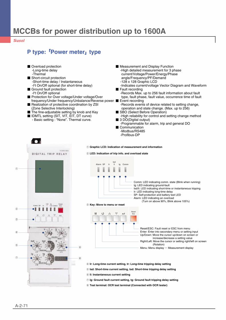
P type: ��Power meter��type
■ Overload protection-Long-time delay-Thermal
■ Short-circuit protection-Short-time delay / Instantaneous-I2t On/Off optional (for short-time delay)
■ Ground fault protection-I2t On/Off optional
■ Protection for Over voltage/Under voltage/Over frequency/Under frequency/Unbalance/Reverse power
■ Realization of protective coordination by ZSI(Zone Selective Interlocking)
■ The fine-adjustable setting by knob and Key■ IDMTL setting (SIT, VIT, EIT, DT curve)
- Basic setting : “None”. Thermal curve.
■ Measurement and Display Function-High detailed measurement for 3 phasecurrent/Voltage/Power/Energy/Phaseangle/Frequency/PF/Demand
-128 x 128 Graphic LCD-Indicates current/voltage Vector Diagram and Waveform
■ Fault recording-Records Max. up to 256 fault information about fault type, fault phase, fault value, occurrence time of fault
■ Event recording-Records events of device related to setting change, operation and state change. (Max. up to 256)
■ SBO (Select Before Operation)-High reliability for control and setting change method
■ 3 DO(Digital output) -Programmable for alarm, trip and general DO
■ Communication-Modbus/RS485-Profibus-DP
① Graphic LCD: Indication of measurement and information
② LED: Indication of trip info. and overload state
Comm: LED indicating comm. state (Blink when running)Ig: LED indicating ground-faultIsd/Ii: LED indicating short-time or instantaneous trippingIr: LED indicating long-time delaySP: Self-protection and battery test LEDAlarm: LED indicating an overload
(Turn on above 90%, Blink above 105%)③ Key: Move to menu or reset
Reset/ESC: Fault reset or ESC from menuEnter: Enter into secondary menu or setting inputUp/Down: Move the cursor up/down on screen or
increase/decrease a setting valueRight/Left: Move the cursor or setting right/left on screen
(Rotation)Menu: Menu display ↔ Measurement display
④ Ir: Long-time current setting, tr: Long-time tripping delay setting
⑤ Isd: Short-time current setting, tsd: Short-time tripping delay setting
⑥ Ii: Instantaneous current setting
⑦ Ig: Ground fault current setting, tg: Ground fault tripping delay setting
⑧ Test terminal: OCR test terminal (Connected with OCR tester)
Alarm SP IrIsdIi Ig Comm
ResetEsc
①
⑧
⑥
②
③
④
⑤
⑦

MCCBs for power distribution up to 1600A
A-2-72
ProtectionLong time
Current setting (A) Ir = In×... 0.4 0.5 0.6 0.7 0.8 0.9 1.0
Time delay (s) tr@(1.5×lr) 12.5 25 50 100 200 300 400 500 Off
Accuracy: ±15% or below tr@(6.0×lr) 0.5 1 2 4 8 12 16 20 Off
100ms tr@(7.2×lr) 0.34 0.69 1.38 2.7 5.5 8.3 11 13.8 Off
Short time
Current setting (A)Isd = Ir×... 1.5 2 3 4 5 6 8 10 Off
Accuracy: ±10%
Time delay (s)tsd
I2t Off 0.05 0.1 0.2 0.3 0.4
@ 10×Ir I2t On 0.1 0.2 0.3 0.4
Min. Trip20 80 160 260 360
(I2t Off)Time(ms)
Max. Trip80 140 240 340 440
Time(ms)
Instantaneous
Current setting (A) Ii = In×... 2 3 4 6 8 10 12 15 Off
Tripping time 50(±10ms)
Ground fault
Pick-up (A)
Accuracy: ±10%(Ig�0.4In) Ig = In×... 0.2 0.3 0.4 0.5 0.6 0.7 0.8 1.0 Off
±20%(Ig≤0.4In)
tgI2t Off 0.05 0.1 0.2 0.3 0.4
I2t On 0.1 0.2 0.3 0.4
Time delay (s) Min. Trip20 80 160 260 360
@ 1×In(I2t Off)
Time(ms)
Max. Trip80 140 240 340 440
Time(ms)
Earth leakage (Option)
Current setting (A) I△n 0.5 1 2 3 5 10 20 30 Off
Time delay (ms) Alarm140 230 350 800 950
Accuracy: ±15%△t
Time(ms)
Trip140 230 350 800
Time(ms)
Other protectionPick-up Time delay(s)
Setting range Step Accuracy Setting range Step Accuracy
Under voltage 80V ~ 0V_Pick-up 1V ±5%
Over voltage UV_Pick-up ~ 980V 1V ±5% 1.2~40sec
Voltage unbalance 6% ~ 99% 1% ±2.5% or (*±10%)
Reverse power 10~500 kW 1kW ±10%0.2~40sec
Over power 500~5000 kW 1kW ±10% 0.1sec ±0.1sec
Current unbalance 6% ~ 99% 1% ±2.5% or (*±10%)
Over 60Hz UF_Pick-up ~ 65 1Hz ±0.1Hz
frequency 50Hz UF_Pick-up ~ 55 1Hz ±0.1Hz 1.2~40sec
Under 60Hz 55Hz ~ OF_Pick-up 1Hz ±0.1Hz
frequency 50Hz 45Hz ~ OF_Pick-up 1Hz ±0.1Hz
t
Ir
tr
I
lsd
Ii
tsd
t
I n
I
t
Note) Earth leakage function is available with ZCT or external CT
PTA(Pre Trip Alarm)
Current setting (A) Ip = Ir x … 0.6 0.65 0.7 0.75 0.8 0.85 0.9 0.95 1
Time delay (s)tp@(1.2×Ip) 1 5 10 15 20 25 30 35 Off
Accuracy: ±15%
t
Ig
I
tg
MCCBs for power distribution up to 1600A
A-2-73
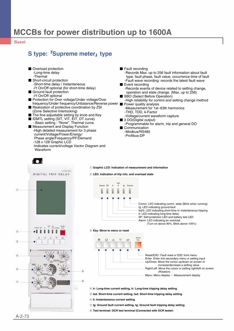
S type: ��Supreme meter��type
■ Overload protection-Long-time delay-Thermal
■ Short-circuit protection-Short-time delay / Instantaneous-I2t On/Off optional (for short-time delay)
■ Ground fault protection-I2t On/Off optional
■ Protection for Over voltage/Under voltage/Overfrequency/Under frequency/Unbalance/Reverse power
■ Realization of protective coordination by ZSI(Zone Selective Interlocking)
■ The fine-adjustable setting by knob and Key■ IDMTL setting (SIT, VIT, EIT, DT curve)
- Basic setting : “None”. Thermal curve.■ Measurement and Display Function
-High detailed measurement for 3 phasecurrent/Voltage/Power/Energy/Phase angle/Frequency/PF/Demand
-128 x 128 Graphic LCD-Indicates current/voltage Vector Diagram andWaveform
■ Fault recording-Records Max. up to 256 fault information about faulttype, fault phase, fault value, occurrence time of fault
-Fault wave recording: records the latest fault wave■ Event recording
-Records events of device related to setting change,operation and state change. (Max. up to 256)
■ SBO (Select Before Operation)-High reliability for control and setting change method
■ Power quality analysis-Measurement for 1st~63th harmonics -THD, TDD, k-Factor-Voltage/current waveform capture
■ 3 DO(Digital output) -Programmable for alarm, trip and general DO
■ Communication-Modbus/RS485-Profibus-DP
① Graphic LCD: Indication of measurement and information
② LED: Indication of trip info. and overload state
Comm: LED indicating comm. state (Blink when running)Ig: LED indicating ground-faultIsd/Ii: LED indicating short-time or instantaneous trippingIr: LED indicating long-time delaySP: Self-protection LED and battery test LEDAlarm: LED indicating an overload
(Turn on above 90%, Blink above 105%)
③ Key: Move to menu or reset
Reset/ESC: Fault reset or ESC from menuEnter: Enter into secondary menu or setting inputUp/Down: Move the cursor up/down on screen or
increase/decrease a setting valueRight/Left: Move the cursor or setting right/left on screen
(Rotation)Menu: Menu display ↔ Measurement display
④ Ir: Long-time current setting, tr: Long-time tripping delay setting
⑤ Isd: Short-time current setting, tsd: Short-time tripping delay setting
⑥ Ii: Instantaneous current setting
⑦ Ig: Ground fault current setting, tg: Ground fault tripping delay setting
⑧ Test terminal: OCR test terminal (Connected with OCR tester)
Alarm SP IrIsdIi Ig Comm
ResetEsc
①
⑧
⑥
②
③
④
⑤
⑦
MCCBs for power distribution up to 1600A
A-2-74
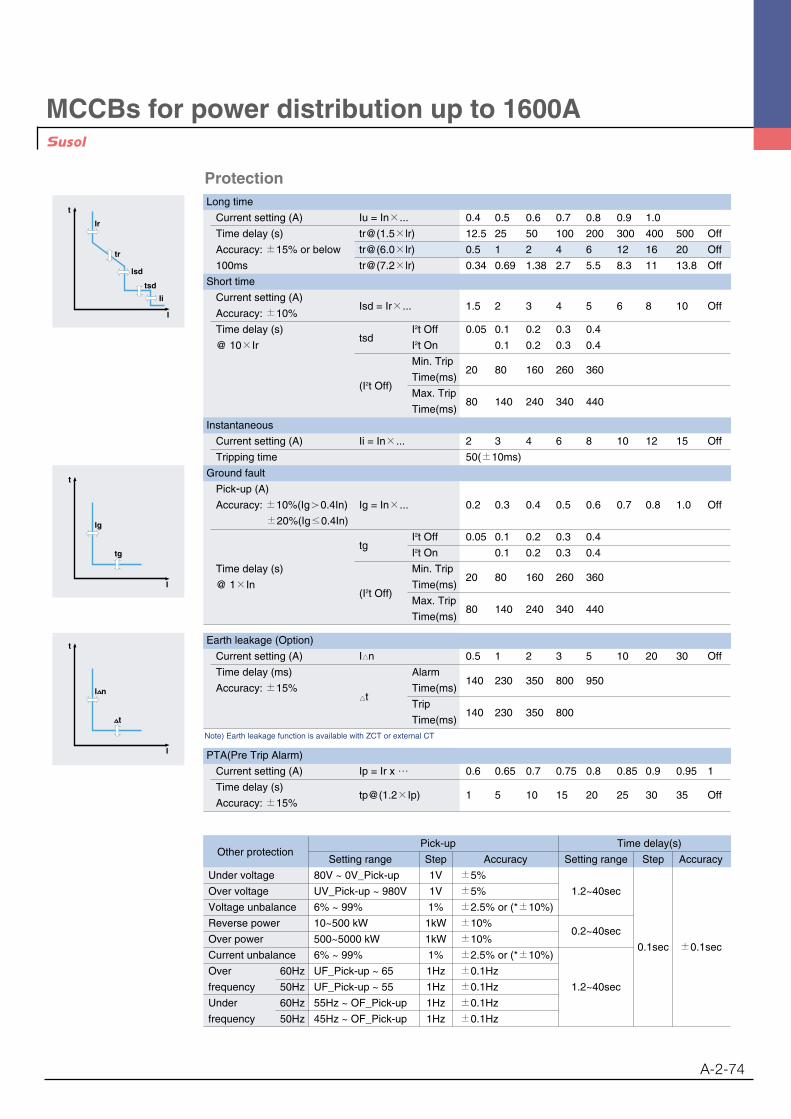
ProtectionLong time
Current setting (A) Iu = In×... 0.4 0.5 0.6 0.7 0.8 0.9 1.0
Time delay (s) tr@(1.5×lr) 12.5 25 50 100 200 300 400 500 Off
Accuracy: ±15% or below tr@(6.0×lr) 0.5 1 2 4 6 12 16 20 Off
100ms tr@(7.2×lr) 0.34 0.69 1.38 2.7 5.5 8.3 11 13.8 Off
Short time
Current setting (A)Isd = Ir×... 1.5 2 3 4 5 6 8 10 Off
Accuracy: ±10%
Time delay (s)tsd
I2t Off 0.05 0.1 0.2 0.3 0.4
@ 10×Ir I2t On 0.1 0.2 0.3 0.4
Min. Trip20 80 160 260 360
(I2t Off)Time(ms)
Max. Trip80 140 240 340 440
Time(ms)
Instantaneous
Current setting (A) Ii = In×... 2 3 4 6 8 10 12 15 Off
Tripping time 50(±10ms)
Ground fault
Pick-up (A)
Accuracy: ±10%(Ig�0.4In) Ig = In×... 0.2 0.3 0.4 0.5 0.6 0.7 0.8 1.0 Off
±20%(Ig≤0.4In)
tgI2t Off 0.05 0.1 0.2 0.3 0.4
I2t On 0.1 0.2 0.3 0.4
Time delay (s) Min. Trip20 80 160 260 360
@ 1×In(I2t Off)
Time(ms)
Max. Trip80 140 240 340 440
Time(ms)
t
Ir
tr
I
lsd
Ii
tsd
t
I n
I
t
Earth leakage (Option)
Current setting (A) I△n 0.5 1 2 3 5 10 20 30 Off
Time delay (ms) Alarm140 230 350 800 950
Accuracy: ±15%△t
Time(ms)
Trip140 230 350 800
Time(ms)Note) Earth leakage function is available with ZCT or external CT
PTA(Pre Trip Alarm)
Current setting (A) Ip = Ir x … 0.6 0.65 0.7 0.75 0.8 0.85 0.9 0.95 1
Time delay (s)
Accuracy: ±15%tp@(1.2×Ip) 1 5 10 15 20 25 30 35 Off
Other protectionPick-up Time delay(s)
Setting range Step Accuracy Setting range Step Accuracy
Under voltage 80V ~ 0V_Pick-up 1V ±5%
Over voltage UV_Pick-up ~ 980V 1V ±5% 1.2~40sec
Voltage unbalance 6% ~ 99% 1% ±2.5% or (*±10%)
Reverse power 10~500 kW 1kW ±10%0.2~40sec
Over power 500~5000 kW 1kW ±10% 0.1sec ±0.1sec
Current unbalance 6% ~ 99% 1% ±2.5% or (*±10%)
Over 60Hz UF_Pick-up ~ 65 1Hz ±0.1Hz
frequency 50Hz UF_Pick-up ~ 55 1Hz ±0.1Hz 1.2~40sec
Under 60Hz 55Hz ~ OF_Pick-up 1Hz ±0.1Hz
frequency 50Hz 45Hz ~ OF_Pick-up 1Hz ±0.1Hz
t
Ig
I
tg
MCCBs for power distribution up to 1600A
A-2-75
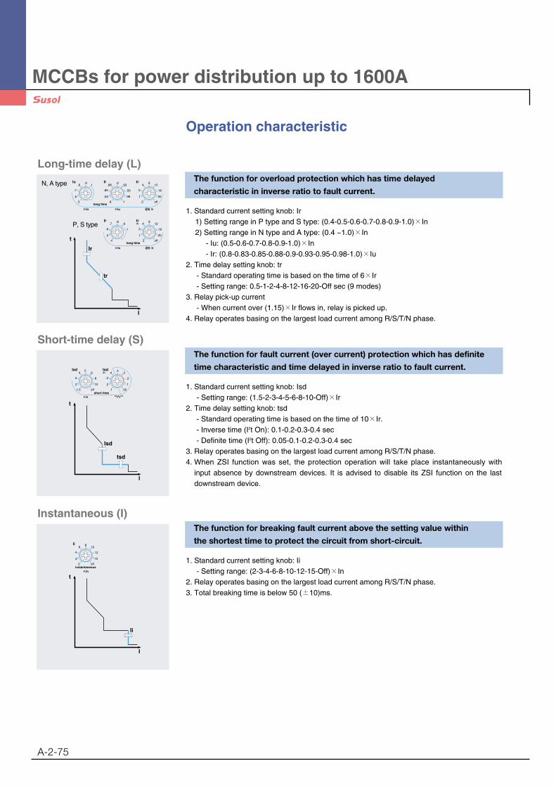
Operation characteristic
The function for overload protection which has time delayed
characteristic in inverse ratio to fault current.
1. Standard current setting knob: Ir1) Setting range in P type and S type: (0.4-0.5-0.6-0.7-0.8-0.9-1.0)×In2) Setting range in N type and A type: (0.4 ~1.0)×In
- Iu: (0.5-0.6-0.7-0.8-0.9-1.0)×In- Ir: (0.8-0.83-0.85-0.88-0.9-0.93-0.95-0.98-1.0)×Iu
2. Time delay setting knob: tr- Standard operating time is based on the time of 6×Ir- Setting range: 0.5-1-2-4-8-12-16-20-Off sec (9 modes)
3. Relay pick-up current- When current over (1.15)×Ir flows in, relay is picked up.
4. Relay operates basing on the largest load current among R/S/T/N phase.
Long-time delay (L)
t
Ir
tr
I
.88
.85
.83
.9.93
.95
.98
.8 1
.8
.7
.6
.91
.5
IrIu
×In ×Iu @6 Ir
4
2
1
812
16
20
.5 off
tr
Iong time
.7
.6
.5
.8.9
1
.4
Ir
×In @6 Ir
4
2
1
812
16
20
.5 off
tr(S)
Iong time
The function for fault current (over current) protection which has definite
time characteristic and time delayed in inverse ratio to fault current.
1. Standard current setting knob: Isd- Setting range: (1.5-2-3-4-5-6-8-10-Off)×Ir
2. Time delay setting knob: tsd- Standard operating time is based on the time of 10×Ir.- Inverse time (I2t On): 0.1-0.2-0.3-0.4 sec- Definite time (I2t Off): 0.05-0.1-0.2-0.3-0.4 sec
3. Relay operates basing on the largest load current among R/S/T/N phase.4. When ZSI function was set, the protection operation will take place instantaneously with
input absence by downstream devices. It is advised to disable its ZSI function on the lastdownstream device.
Short-time delay (S)
t
I
tsd
Isd
.4
.3
.2
.4.3
.2
.1
.1 .05
tsd(S)4
3
2
56
8
10
1.5 off
Isd
×Ir onI2toffshort time
The function for breaking fault current above the setting value within
the shortest time to protect the circuit from short-circuit.
1. Standard current setting knob: Ii- Setting range: (2-3-4-6-8-10-12-15-Off)×In
2. Relay operates basing on the largest load current among R/S/T/N phase.3. Total breaking time is below 50 (±10)ms.
Instantaneous (I)
t
I
Ii
6
4
3
810
12
15
2 off
Ii
×Ininstantaneous
N, A type
P, S type

MCCBs for power distribution up to 1600A
A-2-76
The function for breaking ground fault current above setting value
after time-delay to protect the circuit from ground fault.
1. Standard setting current knob: Ig- Setting range: (0.2-0.3-0.4-0.5-0.6-0.7-0.8-1.0-Off)×In
2. Time delay setting knob: tg- Inverse time (I2t On): 0.1-0.2-0.3-0.4 sec- Definite time (I2t Off): 0.05-0.1-0.2-0.3-0.4 sec
3. Ground fault current is vector sum of each phase current. Therefore, 3Pole products mayoperate under its phase-unbalance including ground fault situations.(R+S+T+(N) Phase)
4. When ZSI function was set, the protection operation will take place instantaneously withinput absence by downstream devices. It is advised to disable its ZSI function on the lastdownstream device.
5. Ground-fault functions are basically provided with products equipped with a trip relay throughits internal CT that is embedded in each phase.(But, it can’t be used with earth-leakageprotection function at the same time)
Ground Fault (G)
t
Ig
I
tg
.4
.3
.2
.4.3
.2
.1
.1 .05
tg(S).5
.4
.3
.6.7
.8
1
.2 off
Ig
×In onI2toffground fault
The function for breaking earth leakage current above setting value after
time delay to protect the circuit from earth leakage. (A, P, S type)
1. Standard setting current knob: I△n- Setting range: 0.5-1-2-3-4-5-10-20-30-Off (A)
2. Time delay setting knob: △t- Trip time: 140-230-350-800 ms- Alarm time: 140-230-350-800-950 ms
3. Settings within its alarm range will prevent its breaker from tripping but activating its alarm.4. This function is enabled and can be used only with standard ZCT provided by LS or private
external CT(secondary output 5A) selected by customers.5. When ZSI function was set, the protection operation will take place instantaneously with
input absence by downstream devices. It is advised to disable its ZSI function on the lastdownstream device.
※Use cautions with earth-leakage current settings- When using a standard ZCT provided by LS, the setting range is from 0.5 to 30A which is
based on its primary current. But MCCB installed like A type (displayed on the left side)should only be cable-connected and its rated current should be less than 1600A.
- When using other CT selected by customers, the setting range is from 0.5 to 5A based onits secondary current.(Secondary output rating : 5A)Hence, under 100:5A CT, if trip relay is set to 0.5A, earth-leakage exceeding 10A willactivate its operation (0.5A×20 = 10A)
※Guideline for the external CT usage- Earth-leakage protection characteristics using the standard CT which is installed inside of
MCCB can protect currents from 20 to 100% range on its rated current. - As rated currents on MCCB increases, current that is covered by its standard CT increase
as well. This can not protect against small leakage currents.ex) 400A MCCB Min. Earth-leakage current 400A×20% =80A
4000A MCCB Min. Earth-leakage current 4000A×20% =800A- Therefore, customers are advised to install an external CT in accordance with its rated
currents within its systems. And choose trip relay(E, X type) which is required with externalCT usage in order to provide earth-leakage functions.
Earth Leakage (G) - Option
t
I
800
350
230
900800
350
230
140 140
(ms)3
2
1
45
10
20
0.5 30trip alarmEarth Leakage
I n
t
I n t
R S T N
ZCT or ExternalCT
A
ZCT or ExternalCT
B

MCCBs for power distribution up to 1600A
A-2-77
Measurement function
Voltage moduleFor P and S type Trip relay, separate voltage module is necessaryto measure other element besides current (Separate purchase is needed)- Voltage input range: AC 60~690V
Class. Measurement
Detailed element Unit Display range Accuracyelement
Line current Ia,Ib,Ic ±3%
Current Normal current I1 A 80A~65,535A
Reverse current I2
Line voltage Vab,Vbc,Vca ±1%
Voltage Phase voltage Va,Vb,Vc
V 60~690V ±1%
Normal voltage V1
Reverse voltage V2
Line-to-line ∠VabIa, ∠VabIb, ∠VabIc, ±1°
Line-to-current ∠VabVbc, ∠VabVca° 0~360°Angle
Phase-to-phase ∠VaVb,∠VaVc ±1°
Phase-to-current ∠VaIa, ∠VbIb, ∠VcIc ±1°
Active power Pa(ab), Pb(bc), Pc(ca), P kW 1kW~99,999kW ±3%
Power Reactive power Qa(ab), Qb(bc), Qc(ca), Q kVar 1kVar~99,999kVar ±3%
Apparent power Sa(ab), Sb(bc), Sc(ca), S kVA 1kVA~99,999kVA ±3%
Active energyWHa(ab), WHb(bc), kWh
1kWh~9999.99MWh ±3%WHc(ca), WH MWh
Reactive energyVARHa(ab), VARHb(bc), kVarh
1kVarh~9999.99MVarh ±3%EnergyVARHc(ca), VARH Mvarh
Reverse active rWHa(ab), rWHb(bc), kWh1kWh ~9999.99MWh ±3%
energy rWHc(ca), rWH MWh
Freq. Frequency F Hz 45~65Hz
Power factor Power factor(PF) PFa(ab), PFb(bc), PFc(ca), PF +: Lead, -: Lag
Unbalance Unbalance rate Iunalance, Vunbalance % 0.0~100.0
Active powerPeak demand kW 1kW~99999kW
Demand demand
Current demand Peak demand A 80A~65,535A
Voltage 1st~63th harmonics ofV 60~690V
harmonics Va(ab),Vb(bc),Vc(ca)
Harmonics Current harmonics 1st~63th harmonics of Ia,Ib,Ic A 80A~65,535A
THD, TDD % 0.0~100.0
K-Factor - 0.0~100.0
Voltagemodule
Voltagemodule
V1V2V3Vn
Vr Vs Vt Vn Vr Vs Vt
V1V2V3Vn
123456789
101112
1314151617181920
123456789
101112
1314151617181920
3P4W wiring 3P3W wiring
A ty
peP
type
S ty
pe