MCCB (Moulded Case Circuit Breaker) for advanced ... · Compact NSX100 to 250 Micrologic 5.2 and...
20
Reinforced discrimination
-
Upload
truongkhue -
Category
Documents
-
view
228 -
download
0
Transcript of MCCB (Moulded Case Circuit Breaker) for advanced ... · Compact NSX100 to 250 Micrologic 5.2 and...

Reinforced discrimination
E-1
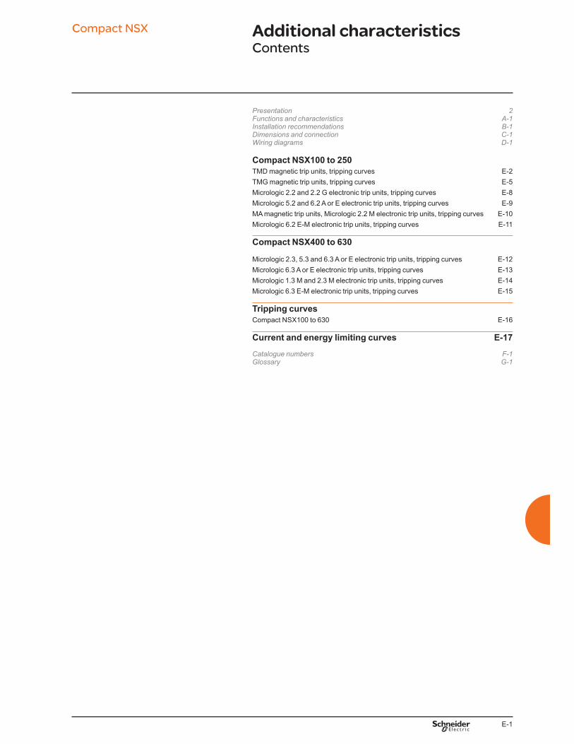
Additional characteristicsContents
Compact NSX
Presentation 2Functions and characteristics A-1Installation recommendations B-1Dimensions and connection C-1Wiring diagrams D-1
Compact NSX100 to 250 TMD magnetic trip units, tripping curves E-2
TMG magnetic trip units, tripping curves E-5
Micrologic 2.2 and 2.2 G electronic trip units, tripping curves E-8
Micrologic 5.2 and 6.2 A or E electronic trip units, tripping curves E-9
MA magnetic trip units, Micrologic 2.2 M electronic trip units, tripping curves E-10
Micrologic 6.2 E-M electronic trip units, tripping curves E-11
Compact NSX400 to 630
Micrologic 2.3, 5.3 and 6.3 A or E electronic trip units, tripping curves E-12
Micrologic 6.3 A or E electronic trip units, tripping curves E-13
Micrologic 1.3 M and 2.3 M electronic trip units, tripping curves E-14
Micrologic 6.3 E-M electronic trip units, tripping curves E-15
Tripping curves Compact NSX100 to 630 E-16
Current and energy limiting curves E-17 Catalogue numbers F-1Glossary G-1

E-2
Compact NSX100 to 250 TMD magnetic trip units, tripping curvesProtection of distribution systems
Additional characteristics
TM16D TM25D
.5 .7 1 2 3 4 5 7 10 20 30 50 70 100 200 300
I / Ir
10 000
5 000
2 000
1 000
500
200
100
50
20
10
5
2
1
.5
.2
.1
.05
.02
.01
.005
.002
.001
t(s)
TM16D : Im = 12 x In
t < 10 ms
DB
41
64
23
.ep
s
.5 .7 1 2 3 4 5 7 10 20 30 50 70 100 200 300
I / Ir
10 000
5 000
2 000
1 000
500
200
100
50
20
10
5
2
1
.5
.2
.1
.05
.02
.01
.005
.002
.001
t(s)
TM25D : Im = 12 x In
t < 10 ms
DB
41
64
25
.ep
s
TM30D/TM32D TM40D
.5 .7 1 2 3 4 5 7 10 20 30 50 70 100 200 300
I / Ir
10 000
5 000
2 000
1 000
500
200
100
50
20
10
5
2
1
.5
.2
.1
.05
.02
.01
.005
.002
.001
t(s)
TM32D : Im = 12.5 x In
TM30D : Im = 10 In
t < 10 ms
DB
42
12
77
.ep
s
.5 .7 1 2 3 4 5 7 10 20 30 50 70 100 200 300
I / Ir
10 000
5 000
2 000
1 000
500
200
100
50
20
10
5
2
1
.5
.2
.1
.05
.02
.01
.005
.002
.001
t(s)
TM40D : Im = 12.5 x In
t < 10 ms
DB
41
64
28
.ep
s

E-3
Compact NSX100 to 250 TMD magnetic trip units, tripping curvesProtection of distribution systems
Additional characteristics
TM50D TM63D
.5 .7 1 2 3 4 5 7 10 20 30 50 70 100 200 300
I / Ir
10 000
5 000
2 000
1 000
500
200
100
50
20
10
5
2
1
.5
.2
.1
.05
.02
.01
.005
.002
.001
t(s)
TM50D : 10 x In
DB
41
64
31
.ep
s
.5 .7 1 2 3 4 5 7 10 20 30 50 70 100 200 300
I / Ir
10 000
5 000
2 000
1 000
500
200
100
50
20
10
5
2
1
.5
.2
.1
.05
.02
.01
.005
.002
.001
t(s)
TM63D : 8 x In
DB
41
64
30
.ep
s
TM80D / TM100D TM125D / TM160D
.5 .7 1 2 3 4 5 7 10 20 30 50 70 100 200 300
I / Ir
10 000
5 000
2 000
1 000
500
200
100
50
20
10
5
2
1
.5
.2
.1
.05
.02
.01
.005
.002
.001
t(s)
TM80D/TM100D :Im = 8 x In
t < 10 ms
DB
41
61
48
.ep
s
.5 .7 1 2 3 4 5 7 10 20 30 50 70 100 200 300
I / Ir
10 000
5 000
2 000
1 000
500
200
100
50
20
10
5
2
1
.5
.2
.1
.05
.02
.01
.005
.002
.001
t(s)
TM160D :Im = 8 x In
TM125D : Im = 10 x In
t < 10 ms
DB
41
61
49
.ep
s

E-4
Compact NSX100 to 250 TMD magnetic trip units, tripping curvesProtection of distribution systems
Additional characteristics
TM200D / TM250D
.5 .7 1 2 3 4 5 7 10 20 30 50 70 100 200 300
I / Ir
10 000
5 000
2 000
1 000
500
200
100
50
20
10
5
2
1
.5
.2
.1
.05
.02
.01
.005
.002
.001
t(s)
TM200D/TM250D :
Im = 5 ... 10 x In
t < 10 ms
DB
41
61
50
.ep
s
For all TDM curves :Values are given for 40 °C ambiant, Ir = 1xIn, 3 poles loaded, cold start.For Ir = k x In, read the time corresponding to 1/k times given current.For 1 pole tripping, read the time corresponding to 0.85 times given current.For hot start (0.9 x Ir), divide max. time by 2, min. time by 4.
0 20 40 60
120
100
80
DB
41
80
02
.ep
s
E-5
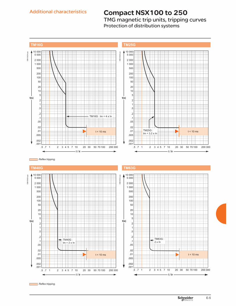
Additional characteristics Compact NSX100 to 250 TMG magnetic trip units, tripping curvesProtection of distribution systems
TM16G TM25G
.5 .7 1 2 3 4 5 7 10 20 30 50 70 100 200 300
I / Ir
10 000
5 000
2 000
1 000
500
200
100
50
20
10
5
2
1
.5
.2
.1
.05
.02
.01
.005
.002
.001
t(s)
TM16G : Im = 4 x In
t < 10 ms
DB
41
64
24
.ep
s
.5 .7 1 2 3 4 5 7 10 20 30 50 70 100 200 300
I / Ir
10 000
5 000
2 000
1 000
500
200
100
50
20
10
5
2
1
.5
.2
.1
.05
.02
.01
.005
.002
.001
t(s)
TM25G :
Im = 3.2 x Int < 10 ms
DB
41
64
26
.ep
s
TM40G TM63G
.5 .7 1 2 3 4 5 7 10 20 30 50 70 100 200 300
I / Ir
10 000
5 000
2 000
1 000
500
200
100
50
20
10
5
2
1
.5
.2
.1
.05
.02
.01
.005
.002
.001
t(s)
TM40G :
Im = 2 x In
t < 10 ms
DB
41
64
29
.ep
s
.5 .7 1 2 3 4 5 7 10 20 30 50 70 100 200 300
I / Ir
10 000
5 000
2 000
1 000
500
200
100
50
20
10
5
2
1
.5
.2
.1
.05
.02
.01
.005
.002
.001
t(s)
TM63G :
2 x In
DB
41
64
32
.ep
s

E-6
Compact NSX100 to 250TMG magnetic trip units, tripping curvesProtection of distribution systems
Additional characteristics
TM80G TM100G
t < 10 ms
TM80G
Im = 2.5 x In
DB
41
62
66
.ep
s
TM100G
Im = 3.2 x In
t < 10 ms
DB
41
62
67
.ep
s
TM125G TM160G
TM125G
Im = 3.5 x In
t < 10 ms
DB
41
62
68
.ep
s
TM160G
Im = 2.75 x In
t < 10 ms
DB
41
62
69
.ep
s

E-7
Compact NSX100 to 250TMG magnetic trip units, tripping curvesProtection of distribution systems
Additional characteristics
TM200G TM250G
TM200G
Im = 2.2 x In
t < 10 ms
DB
41
62
70
.ep
s
TM250G
Im = 2.1 x In
t < 10 ms
DB
41
62
71
.ep
s

E-8
Compact NSX100 to 250Micrologic 2.2 and 2.2 G electronic trip
units, tripping curvesProtection of distribution systems
Additional characteristics
Micrologic 2.2 - 40... 160 A Micrologic 2.2 - 250 A
.5 .7 1 2 3 4 5 7 10 20 30 50 70 100 200 300
I / Ir
10 000
5 000
2 000
1 000
500
200
100
50
20
10
5
2
1
.5
.2
.1
.05
.02
.01
.005
.002
.001
t(s)
t < 10 ms
Isd = 1.5 ...10 x Ir
Ii = 15 x In
40 A : Ir = 16 ...40 A
100 A : Ir = 36 ...100 A
160 A : Ir = 57 ...160 ADB
41
61
51
.ep
s
.5 .7 1 2 3 4 5 7 10 20 30 50 70 100 200 300
I / Ir
10 000
5 000
2 000
1 000
500
200
100
50
20
10
5
2
1
.5
.2
.1
.05
.02
.01
.005
.002
.001
t(s)
Ii = 12 x In
t < 10 ms
250 A : Ir = 90 ...250 A
Isd = 1.5 ...10 x Ir
DB
41
61
52
.ep
s
Micrologic 2.2 G - 40... 160 A Micrologic 2.2 G - 250 A
.5 .7 1 2 3 4 5 7 10 20 30 50 70 100 200 300
I / Ir
10 000
5 000
2 000
1 000
500
200
100
50
20
10
5
2
1
.5
.2
.1
.05
.02
.01
.005
.002
.001
t(s)
Ii = 15 x In
t < 10 ms
40 A : Ir = 16 ...40 A
100 A : Ir = 36 ...100 A
160 A : Ir = 57 ...160 A
Isd = 1.5 ...9 x Ir
DB
41
61
53
.ep
s
.5 .7 1 2 3 4 5 7 10 20 30 50 70 100 200 300
I / Ir
10 000
5 000
2 000
1 000
500
200
100
50
20
10
5
2
1
.5
.2
.1
.05
.02
.01
.005
.002
.001
t(s)
Ii = 12 x In
t < 10 ms
250 A : Ir = 90 ...250 A
Isd = 1.5 ...9 x Ir
DB
41
61
54
.ep
s

E-9
Compact NSX100 to 250Micrologic 5.2 and 6.2 A or E electronic trip
units, tripping curvesProtection of distribution systems
Additional characteristics
Micrologic 5.2 and 6.2 A or E - 40... 160 A Micrologic 5.2 and 6.2 A or E - 250 A
.5 .7 1 2 3 4 5 7 10 20 5 7 10 20 30 50
10 000
5 000
2 000
1 000
500
200
100
50
20
10
5
2
1
.5
.2
.1
.05
.02
.01
.005
.002
.001
t(s)
I / Ir I / In
0.40.30.2
0.1
0
I²t OFF
t < 10 ms
I²t ON
40 A : Ir = 16 ...40 A
100 A : Ir = 36 ...100 A
160 A : Ir = 56 ...160 A
tr = 0.5 ...16 s
Isd = 1.5 ...10 x Ir
Ii = 1.5 ...15 In
DB
41
61
55
.ep
s
.5 .7 1 2 3 4 5 7 10 20 5 7 10 20 30 50
10 000
5 000
2 000
1 000
500
200
100
50
20
10
5
2
1
.5
.2
.1
.05
.02
.01
.005
.002
.001
t(s)
I / Ir I / In
0.40.30.20.1
0
I²t OFF
I²t ON
t < 10 ms
250 A : Ir = 90 ...250 A
Ii = 1.5 ...12 In
Isd = 1.5 ...10 x Ir
tr = 0.5 ...16 s
DB
41
61
56
.ep
s
Micrologic 6.2 A or E (ground-fault protection)
.05 .07 .1 .2 .3 .4 .5 .7 1 2 3 5 7 10 20 30
I / In
10 000
5 000
2 000
1 000
500
200
100
50
20
10
5
2
1
.5
.2
.1
.05
.02
.01
.005
.002
.001
t(s)
I²t OFF
I²t ON
0
0.40.30.20.1
40 A : Ig = 0.4 ...1 x In
> 40 A : Ig = 0.2 ...1 x In
4
DB
11
47
72
.ep
s

E-10
Compact NSX100 to 250MA magnetic trip units, Micrologic 2.2 M
electronic trip units, tripping curvesMotor protection
Additional characteristics
MA2.5... MA100 MA150 and MA220
.5 .7 1 2 3 4 5 7 10 20 30 50 70 100 200 300
I / Ir
10 000
5 000
2 000
1 000
500
200
100
50
20
10
5
2
1
.5
.2
.1
.05
.02
.01
.005
.002
.001
t(s)
Im = 6 ... 14 x In
Im = 9 ... 14 x In
(MA100 4P)
Thermal withstand
t < 10 ms
DB
41
61
57
.ep
s
.5 .7 1 2 3 4 5 7 10 20 30 50 70 100 200 300
I / Ir
10 000
5 000
2 000
1 000
500
200
100
50
20
10
5
2
1
.5
.2
.1
.05
.02
.01
.005
.002
.001
t(s)
Im = 9 ... 14 x In
MA150
MA220
Thermal withstand
t < 10 ms
DB
41
61
58
.ep
s
Micrologic 2.2 M - 25 A Micrologic 2.2 M - 50... 220 A
.5 .7 1 2 3 4 5 7 10 20 30 50 70 100 200 300
I / Ir
10 000
5 000
2 000
1 000
500
200
100
50
20
10
5
2
1
.5
.2
.1
.05
.02
.01
.005
.002
.001
t(s)
Ii = 17 x In
t < 10 ms
25 A : Ir = 12 ...25 A
Isd = 5 ...13 x Ir
class 20
class 10
class 5
DB
41
61
59
.ep
s
.5 .7 1 2 3 4 5 7 10 20 30 50 70 100 200 300
I / Ir
10 000
5 000
2 000
1 000
500
200
100
50
20
10
5
2
1
.5
.2
.1
.05
.02
.01
.005
.002
.001
t(s)
Ii = 15 x In
t < 10 ms
50 A : Ir = 25 ...50 A
100 A : Ir = 50 ...100 A
150 A : Ir = 70 ...150 A
220 A : Ir = 100 ...220 A
class 20class 10
class 5
Isd = 5 ...13 x Ir
DB
41
61
60
.ep
s

E-11
Compact NSX100 to 250Micrologic 6.2 E-M electronic trip units,
tripping curvesMotor protection
Additional characteristics
Micrologic 6.2 E-M - 25 A Micrologic 6.2 E-M - 50... 220 A
.5 .7 1 2 3 4 5 7 10 20 30 50 70 100 200 300
I / Ir
10 000
5 000
2 000
1 000
500
200
100
50
20
10
5
2
1
.5
.2
.1
.05
.02
.01
.005
.002
.001
t(s)
Ii = 17 x In
t < 10 ms
25 A : Ir = 12 ...25 A
class 30
class 20
class 10
class 5
Isd = 5 ...13 x Ir
DB
41
61
61
.ep
s
.5 .7 1 2 3 4 5 7 10 20 30 50 70 100 200 300
I / Ir
10 000
5 000
2 000
1 000
500
200
100
50
20
10
5
2
1
.5
.2
.1
.05
.02
.01
.005
.002
.001
t(s)
Ii = 15 x In
t < 10 ms
50 A : Ir = 25 ...50 A
80 A : Ir = 35 ...80 A
150 A : Ir = 70 ...150 A
220 A : Ir = 100 ...220 A
class 30
class 20
class 10
class 5
Isd = 5 ...13 x Ir
DB
41
61
62
.ep
s
Micrologic 6.2 E-M (ground-fault protection)
.05 .07 .1 .2 .3 .4 .5 .7 1 2 3 5 7 10 20 30
I / In
10 000
5 000
2 000
1 000
500
200
100
50
20
10
5
2
1
.5
.2
.1
.05
.02
.01
.005
.002
.001
t(s)
4
0
0.40.30.20.1
0
0.40.30.20.1
25 A : Ig = 0.6 ...1 x In
50 A : Ig = 0.3 ...1 x In
> 50 A : Ig = 0.2 ...1 x In
DB
11
47
91
.ep
s

E-12
Compact NSX400 to 630Micrologic 2.3, 5.3 and 6.3 A or E electronic
trip units, tripping curvesProtection of distribution systems
Additional characteristics
Micrologic 2.3 - 250... 400 A Micrologic 2.3 - 630 A
.5 .7 1 2 3 4 5 7 10 20 30 50 70 100 200 300
I / Ir
10 000
5 000
2 000
1 000
500
200
100
50
20
10
5
2
1
.5
.2
.1
.05
.02
.01
.005
.002
.001
t(s)
Ii = 12 x In
t < 10 ms
250 A : Ir = 63 ...250 A
400 A : Ir = 144 ...400 A
Isd = 1.5 ...10 x Ir
DB
41
61
63
.ep
s
.5 .7 1 2 3 4 5 7 10 20 30 50 70 100 200 300
I / Ir
10 000
5 000
2 000
1 000
500
200
100
50
20
10
5
2
1
.5
.2
.1
.05
.02
.01
.005
.002
.001
t(s)
Ii = 11 x In
t < 10 ms
630 A : Ir = 225 ...630 A
Isd = 1.5 ...10 x Ir
DB
41
61
64
.ep
s
Micrologic 5.3 and 6.3 A or E - 400 A Micrologic 5.3 and 6.3 A or E - 630 A
.5 .7 1 2 3 4 5 7 10 20 5 7 10 20 30 50
10 000
5 000
2 000
1 000
500
200
100
50
20
10
5
2
1
.5
.2
.1
.05
.02
.01
.005
.002
.001
t(s)
I / Ir I / In
0.40.30.20.1
0
I²t OFF
t < 10 ms
I²t ON
400 A : Ir = 100 ...400 A
tr = 0.5 ...16 s
Isd = 1.5 ...10 x Ir
Ii = 1.5 ...12 In
DB
41
61
65
.ep
s
.5 .7 1 2 3 4 5 7 10 20 5 7 10 20 30 50
10 000
5 000
2 000
1 000
500
200
100
50
20
10
5
2
1
.5
.2
.1
.05
.02
.01
.005
.002
.001
t(s)
I / Ir I / In
0.40.30.20.1
0
I²t OFF
I²t ON
t < 10 ms
630 A : Ir = 225 ...630 A
Isd = 1.5 ...10 x Ir
Ii = 1.5 ...11 In
tr = 0.5 ...16 s
DB
41
61
66
.ep
s

E-13
Compact NSX400 to 630Micrologic 6.3 A or E electronic trip units,
tripping curvesProtection of distribution systems
Additional characteristics
Micrologic 6.3 A or E (ground-fault protection)
.05 .07 .1 .2 .3 .4 .5 .7 1 2 3 5 7 10 20 30
I / In
10 000
5 000
2 000
1 000
500
200
100
50
20
10
5
2
1
.5
.2
.1
.05
.02
.01
.005
.002
.001
t(s)
I²t OFF
I²t ON
0
0.40.30.20.1
40 A : Ig = 0.4 ...1 x In
> 40 A : Ig = 0.2 ...1 x In
4
DB
11
47
72
.ep
s

E-14
Compact NSX400 to 630Micrologic 1.3 M and 2.3 M electronic trip
units, tripping curvesMotor protection
Additional characteristics
Micrologic 1.3 M - 320 A Micrologic 1.3 M - 500 A
.5 .7 1 2 3 4 5 7 10 20 30 50 70 100 200 300
I / In
10 000
5 000
2 000
1 000
500
200
100
50
20
10
5
2
1
.5
.2
.1
.05
.02
.01
.005
.002
.001
t(s)
Ii = 15 x In
Thermal withstand
t < 10 ms
Isd = 5 ...13 x In
DB
41
61
67
.ep
s
.5 .7 1 2 3 4 5 7 10 20 30 50 70 100 200 300
I / In
10 000
5 000
2 000
1 000
500
200
100
50
20
10
5
2
1
.5
.2
.1
.05
.02
.01
.005
.002
.001
t(s)
Ii = 13 x In
t < 10 ms
Thermal withstand
Isd = 5 ...13 x InD
B4
16
16
8.e
ps
Micrologic 2.3 M - 320 A Micrologic 2.3 M - 500 A
.5 .7 1 2 3 4 5 7 10 20 30 50 70 100 200 300
I / Ir
10 000
5 000
2 000
1 000
500
200
100
50
20
10
5
2
1
.5
.2
.1
.05
.02
.01
.005
.002
.001
t(s)
Ii = 15 x In
t < 10 ms
320 A : Ir = 160 ...320 A
class 20
class 10
class 5
Isd = 5 ...13 x Ir
DB
41
61
69
.ep
s
.5 .7 1 2 3 4 5 7 10 20 30 50 70 100 200 300
I / Ir
10 000
5 000
2 000
1 000
500
200
100
50
20
10
5
2
1
.5
.2
.1
.05
.02
.01
.005
.002
.001
t(s)
Ii = 13 x In
t < 10 ms
500 A : Ir = 250 ...500 A
class 20
class 10
class 5
Isd = 5 ...13 x Ir
DB
41
61
70
.ep
s

E-15
Additional characteristics
Micrologic 6.3 E-M - 320 A Micrologic 6.3 E-M - 500 A
.5 .7 1 2 3 4 5 7 10 20 30 50 70 100 200 300
I / Ir
10 000
5 000
2 000
1 000
500
200
100
50
20
10
5
2
1
.5
.2
.1
.05
.02
.01
.005
.002
.001
t(s)
Ii = 15 x In
t < 10 ms
320 A : Ir = 160 ...320 A
class 30
class 20
class 10
class 5
Isd = 5 ...13 x Ir
DB
41
61
71
.ep
s
.5 .7 1 2 3 4 5 7 10 20 30 50 70 100 200 300
I / Ir
10 000
5 000
2 000
1 000
500
200
100
50
20
10
5
2
1
.5
.2
.1
.05
.02
.01
.005
.002
.001
t(s)
Ii = 13 x In
t < 10 ms
500 A : Ir = 250 ...500 A
class 30
class 20
class 10
class 5
Isd = 5 ...13 x Ir
DB
41
61
72
.ep
s
Micrologic 6.3 E-M (ground fault protection)
.05 .07 .1 .2 .3 .4 .5 .7 1 2 3 5 7 10 20 30
I / In
10 000
5 000
2 000
1 000
500
200
100
50
20
10
5
2
1
.5
.2
.1
.05
.02
.01
.005
.002
.001
t(s)
4
0
0.40.30.20.1
0
0.40.30.20.1
Ig = 0.2 ...1 x In
DB
11
56
34
.ep
s
Compact NSX400 to 630Micrologic 6.3 E-M electronic trip units,
tripping curvesMotor protection

E-16
Tripping curvesCompact NSX100 to 630
Additional characteristics
Compact NSX100 to 630 devices incorporate the
This system breaks very high fault currents.
The device is mechanically tripped via a "piston"
actuated directly by the pressure produced in the
breaking units by the short-circuit.
break, thereby ensuring discrimination.
circuit-breaker rating.
3
4
5
6
7
8
10
20
2 3 4 6 10 20 30 40 60 100 200
t
(ms)
kA rms
NSX630
NSX400
NSX250
NSX100
NSX160
DB
11
57
21
.ep
s

E-17
Additional characteristics Current and energy limiting curves
The limiting capacity of a circuit breaker is its aptitude
to let through a current, during a short-circuit, that is
less than the prospective short-circuit current.
Ics = 100 % IcuThe exceptional limiting capacity of the Compact NSX range greatly reduces the
forces created by fault currents in devices.
The result is a major increase in breaking performance.
b b v it conducts the rated current without abnormal temperature rise
v v suitability for isolation is not impaired.
Longer service life of electrical installationsCurrent-limiting circuit breakers greatly reduce the negative effects of short-circuits
on installations.
Thermal effects
Mechanical effectsReduced electrodynamic forces, therefore less risk of electrical contacts or busbars
being deformed or broken.
Electromagnetic effects
Economy by means of cascadingCascading is a technique directly derived from current limiting. Circuit breakers with
breaking capacities less than the prospective short-circuit current may be installed
downstream of a limiting circuit breaker. The breaking capacity is reinforced by the
limiting capacity of the upstream device. It follows that substantial savings can be
made on downstream equipment and enclosures.
Current and energy limiting curvesThe limiting capacity of a circuit breaker is expressed by two curves which are a
b b 2
Example
page E-18
Maximum permissible cable stressesThe table below indicates the maximum permissible thermal stresses for cables
2s.
CSA 1.5 mm² 2.5 mm² 4 mm² 6 mm² 10 mm²
PVC Cu 2.97x10⁴ 8.26x10⁴ 2.12x10⁵ 4.76x10⁵ 1.32x10⁶
Al 5.41x10⁵
PRC Cu 4.10x10⁴ 1.39x10⁵ 2.92x10⁵ 6.56x10⁵ 1.82x10⁶
Al 7.52x10⁵
CSA 16 mm² 25 mm² 35 mm² 50 mm²
PVC Cu 3.4x10⁶ 8.26x10⁶ 1.62x10⁷ 3.31x10⁷
Al 1.39x10⁶ 3.38x10⁶ 6.64x10⁶ 1.35x10⁷
PRC Cu 4.69x10⁶ 1.39x10⁷ 2.23x10⁷ 4.56x10⁷
Al 1.93x10⁶ 4.70x10⁶ 9.23x10⁶ 1.88x10⁷
Example
The table above indicates that the permissible stress is 1.32x10⁶ A2s.
limited with a thermal stress less than 6x10⁵ A2 page E-18
Cable protection is therefore ensured up to the limit of the breaking capacity of the
circuit breaker.
(t)
ProspectiveIsc peak
(Isc)
Prospectivecurrent
ProspectiveIsc
Limited Iscpeak
Actualcurrent
LimitedIsc
DB
11
57
19
.ep
s
The exceptional limiting capacity of the Compact NSX range is due to the rotating double-break technique (very rapid natural repulsion of contacts and the appearance of two arc voltages in-series with a very steep wave front).

E-18
Current and energy limiting curves
Additional characteristics
Current-limiting curves
Voltage 400/440 V AC Voltage 660/690 V AC
Limited short-circuit current (k peak) Limited short-circuit current (k peak)
2 3 4 6 10 20 30 40 6065
100 200 300
300
200
146
100
80706050
40
30
20
10
87654
kA rms
k peak
NSX400
NSX250
NSX100
NSX160
NSX630LS
R
HN
F L RS
HN
FB
DB
41
34
32
.ep
s
2 3 4 6 10 20 30 40 6065
100 200 300
300
200
146
100
80706050
40
30
20
10
87654
L
HB1
HB1
HB2
HB2
L
S
S
H
R
R
F, N
FN, H
kA rms
k peak
NSX630
NSX400
NSX250
NSX100
NSX160
DB
41
34
33
.ep
s

E-19
Current and energy limiting curves
Additional characteristics
Energy-limiting curves
Voltage 400/440 V AC Voltage 660/690 V AC
Limited energy Limited energy
2 3 4 6 10 20 30 4050 70 100 150200 300
3
5
106
2
3
5
107
2
3
5
108
2
1.41
3
5
109
A2s
B
NSX630
NSX400
NSX250
NSX100
NSX160
LSHF N
LSH
R
RF N
kA rms
2
105
3
5
2
DB
41
34
34
.ep
s
2 3 4 6 10 20 30 4050 70 100 150200 300
3
5
106
2
3
5
107
2
3
5
108
2
1.41
3
5
109
A2s
kA rms
2
105
3
5
2
N, H
H
NSX630
NSX400
NSX250
NSX100
NSX160
L
L
S
R HB1 HB2
R HB1 HB2
S
F, N
FD
B4
13
43
5.e
ps