MCB BONEGA P-E-P · PDF fileBONEGAfi P-E-P Miniature Circuit Breakers ... The BONEGA P-E-P...
34
Transcript of MCB BONEGA P-E-P · PDF fileBONEGAfi P-E-P Miniature Circuit Breakers ... The BONEGA P-E-P...


BONEGA® P-E-P Circuit Breakers (MCB) to 63 A
What do you get by using MCB BONEGA® P-E-P ?
Superior Security and ProtectionYour circuits will be better protected. It's provided by a high short-circuitresistance (below 5 ms). The quicker the whole short-circuit process is finished,the less damage inflicted to the connected devices.
... page 3
Guaranteed ReliabilityUnique resistant construction and careful product control ensure error freefunction. We fully trust in our product – as we are one of the few that are able toguarantee a three-year-warranty.
... page 10
Faster Assembly and Easy MaintenanceTime saving. Our research team (combined with installer and customerfeedback) has incorporated many advantages to make assembling andmaintenance easier and faster than ever before. For example: locking bars,avoiding an incorrect placing of a conductor, a variable input or output, a biggerlocking bar, a user’s inscription and more.
... page 14
Price/qualityYou will get the highest quality possible MCB. Even though it is one of themost advanced miniature circuit breakers in the world, high priced by experts(for example „Gold Amper 2005“, its very affordable.
... page 25
World Unique ProductYou will work with one of the most useful MCB in the world.BONEGA® P-E-P Circuit Breakers have reached this position thanks to technicalparameters, which increase circuit protection to the new level.
... page 31

BONEGA® P-E-P Miniature Circuit Breakers
Superior security and protection
1. Extraordinary High-Speed Break
The BONEGA P-E-P MCB's have reached the highest breaking rate of any MCB (from 2 to 5 times higher thanany other MCB).
An extraordinary high breaking rate beginning from the initiation of a short-circuit to its termination amounts tomax. 5 ms (with a maximum load).
The BONEGA P-E-P MCB's do not reach that high rate to the detriment of the higher arc voltage which raises therisk of protected parts (e.g. motors) considerably. As compared to other MCB´s, the arc voltage is equal or lower.
The high-speed switch-off consists of three stages:
� stage 1 – disconnection of contacts� stage 2 – arc running into the chamber� stage 3 – arc burning termination
The principal advantage of our MCB´s consists of an extraordinary high speed within the first two stages. The third
P-E-P (Perfect Electric Protector)
Improvements that increase security andprotection:
1. Extraordinary High-speed Break
2. Guaranteed Short-Circuit Resistance
3. Reduction of Undesirable Power during a Short-Circuit
4. Locking Protection
5. Simultaneous Switching of the Multi-Module's6. Revolutionary Designed Extinguishing Chamber
7. Durability
8. Terminal Resistant to Inter-Phase Short-Circuit
9. Vibration Resistance
10. Protection Against Hacking of an MCB
11. Higher Safety Standards
12. Wide Selectivity
13. Colored Control Levers
14. The Ability to Seal the Lever in an ON or OFFposition
The sooner the entire short-circuit process is terminated,the less damage there is to connected devices and wiring.
3

stage is very quick, as well, but it is not so essential in the framework of the total speed. Within this last stage, it ismost essential that the chamber is so well constructed that the arc does not “jump-out” in any direction (especially itdoes not come back to the contacts at all).
An almost textbook run of the short-circuit process is caused also by the suitable adjustment of the contact thrust.These contacts do not deviate by the influence of aerodynamic forces (as obvious from the charts at our webpages).
Note: Some producers mention only the speed of contact disconnection (which is the first stage) instead of the total breakingspeed. In the moment of contact disconnection, the power is still flowing through the circuit (voltage and current) because of thecreated arc. In this stage, the MCB has not disconnected the circuit yet.
Conclusion:
� Our curve of breaking procedure is fully unique (an example how an MCB should protect).� The extremely high breaking rate will not endanger the end user, but – in contrast – it will protect him better� The extraordinary breaking rate of the BONEGA P-E-P MCB's provides the most sensitive protection of
human lives, electrical devices within a circuit, and wiring itself.
More information: oscilograms and graphs
2. Guaranteed Short-Circuit Resistance
Our primacy consists in the breaking capacity of 10 kA up to the highest value of 63A, even with the curve “D”pursuant to CSN EN 60898 (nobody has reached it yet).
Our worldwide uniqueness consists in integration of the following phenomena with the kept breakingcapacity of 10 kA:
I.) It is necessary to be aware of that the inside MCB´s resistance affects – inter alia – the breaking capacity.With the low nominal values (e.g. 1A), almost every producer can pride himself that his MCB theoretically hasan unlimited breaking capacity. The higher is the nominal current, the lower is the assistance of the insideMCB´s resistance to absorb the short-circuit process. The nominal current crucial value is at 25A MCB´s and thevery critical ones is at the highest value, i.e. 63A within the curve “D”. If the experts want to detect the MCB´squality, so they always use the aforementioned crucial values (25A and 63A). Within these values, the design ofthe breaking mechanism, contacts, extinguishing chamber etc. becomes known very clearly.
The essential difference, as compared to the MCB´s of several producers, consists in the reached range ofnominal currents, which is reached with the mentioned breaking capacity (25 kA, 15kA, 10kA, 6kA ...). We arepreparing the upper limit of the nominal currents, which can be reached by our MCB´c within their breakingcapacity 25 kA and 15kA.
II.) Another important difference consists in the standard, in accordance with which the producer has achived hiscertification. In Europe, there are two basic standards, namely:
a) the so-called „industrial“ standard CSN EN 60947
b) the so-called „household“ standard CSN EN 60898
As to their relations to breaking capacities, the standards differ e.g. in their requirements of short-circuit quantity,which a MCB has to withstand without disablement of its function. That means one short circuit pursuant to thestandard �SN EN 60947 and three successive short-circuits pursuant to the standard �SN EN 60898.
As resulting from the above, the industrial standard is significantly softer. For many people, that requirement ofthe standard seems to be illogical, but is takes into consideration the behavior of a user, after the circuit hasbeen broken by a MCB. The reaction of the user in a household often is that he tries to switch-on the MCB forthe first, second and third time and just after that he begins to trace the cause. In contrary, a professionalelectrician tries to switch-on it only once and if the MCB breaks again, he begins to trace the cause immediately.
III.) Take into account also the third significant difference – the width of a MCB. There are some MCB´s with aneven higher breaking capacity, but they are in a 1,5-modular or double-modular design.
Notice at other producers, according to which standard and up to which nominal current values they
The MCB´s BONEGA P-E-P can be used underthe most difficult short-circuit conditions.
4

mention the breaking capacity. You can be surprised by the results of worldwide-accredited producers.
The above parameters are caused by the distinguishing chamber, which is one of our two worldwide-acknowledged Czech patents within the MCB P-E-P. Its extraordinary properties could be seen also at the preparedDPN (there is a MCB + switch within one module of 17,5 mm). In this case, we have also overcame the breakingcapacity limitation of 4,5 kA which had been reached worldwide pursuant to the standard �SN EN 60898.
The MCBˇs with a short-circuit resistance up to 15 kA are tested now. As to the single-modular design of thoseMCB´s (width 17,5 mm) and the given range of nominal currents, we would be the only ones worldwide. Theprepared MCB´s BONEGA P-E-P with the breaking capacity of 15 kA can find their application especially in specialworks where they can replace the 1,5 or double modular MCB´s.
3. Reduction of Undesirable Power During a Short-Circuit
It is a very important property of a MCB, which is often marginalized by the public.The quality of the MCB protection is also conditioned by the amount of power that “flows”through the MCB during short-circuit. Its amount is given by the relation: E = I2.t.
As resulting from the mentioned relation, the high breaking rate of the MCB´s BONEGA P-E-P reduces that undesirable power. The standard CSN 60898+A1/A11 states the power limitsbased of which the MCB´s are classified. The category (class) is mentioned on a MCB in theframe below the breaking capacity.
Our MCB´s reach the limits of the 3rd (the highest possible) class without power limitation pursuant to CSN60898+A1/A11, namely even with the nominal breaking capacity of 10 kA.
The following tables show the requirements of the standard for the MCB up to 16A and above 16A up to 32A incl., atvarious nominal short-circuit capacities.
The power limiting class reached by a MCB is an essential element for assessment of its protective function. Wehave met the third power limiting class within the whole range requested (as one of few producers), even with therated short-circuit capacity of 10 kA. The following tables present e.g. the standard requirements for the MCB up to16 A, and above 16A up to 32A incl. with different rated short-circuit capacities.
The lower the power within a short-circuit,the less damage to the connected devices and wiring.
Permitted values I2t for the MCB´s with the rated current up to 16 A incl.
Rated short-circuitcapacity
(A)
Power limiting classes
1 2 3
max. I2t
A2s
max. I2t
A2s
max. I2t
A2s
type B a type C type B type C type B type C
3 000
The limits not stated
31 000 37 000 15 000 18 0004 500 60 000 75 000 25 000 30 0006 000 100 000 120 000 35 000 42 000
10 000 240 000 290 000 70 000 84 000
(the values written in bold digits are valid for our MCB´s BONEGA®, series P-E-P):
Permitted values I2t for the MCB´s with the rated current above 16 A and up to 32 A incl.
Rated short-circuitcapacity
(A)
Power limiting classes
1 2 3
max. I2t
A2s
max. I2t
A2s
max. I2t
A2s
type B a type C type B type C type B type C
3 000
The limits not stated
40 000 50 000 18 000 22 0004 500 80 000 100 000 32 000 39 0006 000 130 000 160 000 45 000 55 000
10 000 310 000 370 000 90 000 110 000
(the values written in bold digits are valid for our MCB´s BONEGA®, series P-E-P):
5

4. Locking Protection
Reasons:
� Because the indication is closely connected with a movable contact, it happens on other MCB´s that themovable contact is locked through the indication by means of a toothpick or a matchstick; thus the completethermal and short-circuit protection of a MCB is out of function. It is not possible to do this on the MCBBONEGA P-E-P, just because of that transparent sight-glass
� Dust protection
This property protects the electro installation companies against claims, which are caused by the end user, whocan be proved wrong with difficulties.
The philosophy of the colored indication ON/OFF is explained within frequent questions at our webpages.
5. Simultaneous Switching of the Multi-Module's
A worldwide unique recently patented system of triggering mechanism which ensures a safe, more accurate andsimultaneous switching of all the contacts at multi-module (pole) miniature circuit breakers; it has been reacheda three-times longer switching distance than that reached by the best competitors world-wide.This advantage enable e.g. continuous start of multi-fuse electric motors (all fuses are switched at the same time).
6. Revolutionary Designed Extinguishing Chamber
The extinguishing chamber is of a fully new patent-protected conception.
a) a very fast “drawing-in” of an arisen electric arc into the chamber
When the movable contact is disconnected from the fixed one, it is necessary to “draw-in” the arisen arc into theextinguishing chamber as soon as possible and to interrupt the circuit definitely. The MCB´s BONEGA P-E-P do notreach that high rate to the detriment of the higher arc voltage which rises the risk of protected parts (e.g. motors)considerably. This could be reached e.g. by higher number of sheets at the extinguishing chamber. Our chamberhas only usual 13 interruptions. As compared to other MCB´s, the arc voltage within the MCB´s BONEGA P-E-P isequal or rather lower.
b) it is not possible the arc to return to the contactsIn other MCB´s, the arc can return to the contacts, so the circuit is connected again. Thanks to the design of thechamber, this phenomenon is not possible in the MCB´s BONEGA P-E-P.
c) fast arc extinctionThe sooner the arc is extinguished, the smaller amount of heat arises. This heat can affect the adjacent circuits(warming of an adjacent MCB)
d) utilization of cold air at the extinguishing chamber for cooling the contactsAt the beginning of short-circuit process, the non-warmed air inside the chamber is used for cooling the contactsimmediately before they are disconnected
The BONEGA P-E-P MCB´s cannot be locked from the outside.
red I - ON, green O - OFF
As the most products, also the MCB´s BONEGA P-E-P has an indication of thecontact conditions. That indicates a real contact condition and not only aposition of the switch-on lever. In case of “sintered” contacts and switched-offlever, the user is clearly informed about flowing current. As the only ones, ourMCB´s have that indication
Connected devices are less strained.
The extinguishing chamber affects the breaking speedand breaking capacity.
6

7. Durability
8. Terminal Resistant to Inter-Phase Short-Circuit
At the upper part of the terminal (serving for interconnection by means of forked strip), the MCB´s body is equippedwith partitions which can be broken of. Those partitions shall avoid a possible inter-phase short-circuit in case ofinterconnection of multi-module types by means of multi-phase interconnecting strips. This short-circuit can becaused by air ionization or humidity, that support electric arc.
9. Vibration Resistance
Strong vibrations can cause the short-circuit release to be put out of service (it loses its protective function) or thespot-welds to be disconnected (current interruption).
a) measures avoiding the short-circuit release to be put out of service
b) measure avoiding the spot welds to be disconnected
The quantity of spot-welds can be reduced significantly. The elements are interconnected by means of a modulardesign, or he parts are made of one piece.
Impact resistant.
The design of the electromagnetic high-speed release with ejecting armature for short-circuit protection has been solved so that it has not any adjustable element. Thecharacteristic is given by the cross-section of the copper wire of the coil, by numberof threads and spring pre-stressing in the core. This solution thus excludes that ourcircuit breakers could change their presented value by a fall or shock.
MCB BONEGA P-E-P eliminates danger of inter-phase short-circuit e.g. just by air ionization.
Animation atwww.bonega.cz
The BONEGA P-E-P MCB´s can be used in equipment with strongvibrations (e.g. railway wagons, site switchboards).
The MCB´s BONEGA P-E-P are protected against the abovephenomenon by a suitable seating of the structure elements,especially of the ejecting coil which is seated in a unique“cradle” (see the Fig.). This design has excluded the possibilityto misalign and consequently to seize the movable core at thecoil.
7

10. Protection Against Hacking of an MCB
The multi-pole MCB´s BONEGA P-E-P cannot be disassembled in such a way that only the interconnection betweenstretching levers would be removed and the individual poles could function separately (e.g. through this, the day andnight tariff rate could be influenced). Especially the distribution companies call for this property.
The mutual phases interconnection does not happen just between the levers, but also by means of pins which areput between the pole and they interfere directly into the inside mechanisms through a side hole. In addition, themulti-pole design is connected with rivets. The interconnecting and covering strip, which is between the levers, isvisibly depreciated. Any interference in a MCB is obvious at first sight.
11. Higher Safety Standards
All locking bars are protected against danger touch and penetration of small foreign objects (IP protection 20).
12. Wide Selectivity
The selectivity means a coordination of two successive breaking devices so that just the disabled wiring part can beswitch-off upon a failure. A wide scale of current values and curves B, C and D enables our MCB´s to be puttogether to various safety cascades. Because of the above, the desired selectivity can be reached.
13. Colored Control Levers
We supply both coloured levers in accordance with the nominal current values (corresponding to the marking ofturn fuses) and black levers.
We comply with the requirements of distributioncompanies for disassembly protection.
Construction of the cover eliminates electrical current injurycaused by touching the circuit breaker.
The MCB´s can be used within combined projects.
The colored levers improve the transparency and comply with therequirements of power plants.
0,2 A - 1,6 A black2 A pink4 A brown6 A green8 A light green
10 A red13 A sandy
16 A grey20 A blue25 A yellow32 A purple40 A black50 A white63 A copper-coloured
8

14. Sealing Under Certain Conditions
(contact: center 6)
Sales Department: - paní Libuše Možnarová, tel. /fax 518 335 216, email : [email protected], 696 66 Sudom��ice nadMoravou 302Secretary of the Company: ing. Roman Hude�ek 603 542 347, [email protected]
The ability to seal the lever in an ON or OFF position.
The lever can be sealed because of openings in bothguiding sidewalls of the switch-off lever. Through theseopenings, a sealing wire can be fed. This sealing wirepasses also through a groove on the movable lever.This groove has been engraved in OFF and ONpositions and it disables the motion of the lever itself.If the lever is sealed in the ON position, the immobilitydoes not render the function of the circuit breakerimpossible. In the event of short-circuit or overload, thecircuit will be shutdown (independently on the fixedposition of the lever). The MCB case enables the leverto be sealed independently on placing the adjacentMCB´s.
9

BONEGA® P-E-P Miniature Circuit Breakers
Guaranteed Reliability
1. Quality Control
The high quality of our product is due to a combination of materials, design and thorough testing of each miniaturecircuit breaker.
a. a triple check of the electromagnetic high-speed release with ejecting armature for short-circuit protection
Every piece manufactured passes through a testing stand controlled by the computer. At that stand, there isverified the function of the circuit breaker on the undermost limit of the required nominal current value forgiven characteristics (B, C or D) by which the switch-off must not occur yet; after that, the current test of theupper limit of the nominal current value of the given characteristic follows immediately - under this current thevelocity of circuit-breaker switching-off must not exceed 0,1 s. This test procedure is repeated three-times.
b. a double check of the time-limit thermal release for overload protection (if the circuit has not been
P-E-P (Perfect Electric Protector)
Improvements that increase reliability:
1. Quality Control
2. Pride of Workmanship
3. Instantaneous Switching of Contacts
4. Casing Resistance to Gaping Upon TerminalInstallation
5. Extremely Rigid Design of Terminals
6. Durability
7. Thermal Dilatation Resistance
8. Vibration Resistance
9. Extraordinary MCB's Body Strength
10. Two Side Molds
It enables us to provide a three year warranty.
Every MCB is thoroughly tested.
10

damaged but a significant overload occurred which could damage the electrical installation)
The thermal release test is done two-times at least until the bi-metal is not mechanically adjusted to therequired value. Between particular tests, the circuit breaker is left to cool down!
The complete test pursuant to CSN EN 60898 - a long-term test of the thermal release at random chosensamples - is performed at least once a shift.
c. at least a fivefold mechanical reliability check: This test is a part of the two aforementioned tests duringwhich the switching-on and switching-off mechanisms are verified.
2. Pride of Workmanship
Every circuit breaker is stamped describing the characteristics, nominal current value, month of manufacture (sincethe beginning of the production) and the number of the individual worker who has assembled the product. In thisway the workers are motivated to bear the liability of their labor.
3. Instantaneous Switching of Contacts
A worldwide unique, recently patented principle of the instantaneous switching where the forcesare transmitted only into the middle of segments – therefore no crossing occurs (no worldmanufacturer has developed that solution yet). This solution has a big influence on extension ofboth mechanical and electrical lifetimes in connection with the number of switching cycles.This unique principle of instantaneous switching of contacts is based on the following facts: evenwhen the MCB lever is stretched very slowly, during the first stage the contacts inside the MCBonly come near to each other to a distance which cannot create the condition for electric arc. Inthis moment the „coming-near“ is interrupted, even if the lever continues to be stretched(switched-on). In this moment the second stage begins – i.e. pre-stressing only inside the
instantaneous mechanism when the contacts does no come near to each other more, but the lever is moved. Uponthe pre-stressing, stated in advance, the third stage begins – i.e. a heavy high-speed switching of internal contacts.This switching is, however, fully independent on the rate of contact lever motion.
The above principle offers the following advantages:
� the contacts can never be burnt even not with a very slow MCB lever motion („stretching“); sometimes theterms „short-circuiting“ or so-called „burning-out“ of contacts are used. It is thus impossible to destroy theMCB in that way.
� by a heavy high-speed switching of contacts, a perfect touch is secured even at very low values of nominalcurrent – such touch excludes any wrong power transfer
� burning of contacts is reduced to a minimum level� the total MCB's lifetime is extended
4. Casing Resistance to Gaping Upon Terminal Installation
Increased responsibility during assembly.
Instantaneous switching extends the mechanicaland electrical life of BONEGA P-E-P MCB's.
There is no gaping of the MCB casingor cross threading of the terminal in the casing.
It is a usual problem on other MCB´s – upon tightening of the terminal, the casingopens or the terminal cross threads in the casing. On some MCB´s, even the jointsand thus the circuit are broken.
11

It is avoided on the MCB´s BONEGA P-E-P by means of:
� plastic guides for the movable parts of the terminal, which has been chosen properly� press-pieces in the casing body� places for rivets, chosen properly� plastic pins (the casing has no butt joins)
5. Extremely Rigid Design of Terminals
The movable terminal has been made of one piece. In contrast to most other MCB´s,the joint has been solved by means of an overlapping and not by a so-called “puzzlejoint”. Through this overlapping goes a screw. It has a double thread length available,which restricts the breaks – “stripping” the thread essentially. The possibility tobreak it when being mounted is fully excluded even if the torque allowed by thestandard is exceeded (more than 2 N.m).
In the bottom part of the clip terminals is the cross grooves which avoid theconductor to be taken out from the terminal (after tightening, the conductor sinks into the grooves).Simultaneously, the contact resistances are limited. (because of the enlargement of the transmission area theburning of the conductor is not possible).
The junction of a conductor and BONEGA® P-E-P MCB is very rigid and reliable.
6. Durability
7. Thermal Dilatation Resistance
The mechanism's function is not affected by thermal dilatation. The design allows possible plays (by dilatation,shock, wearing) to be accepted without any affect on the function of movable parts, such as switching mechanism,movable contact, ejecting coil, indication etc. This unique solution improves the quality essentially but especially itwarranties the reliability under different, even very extreme operational conditions.
8. Vibration Resistance
Strong vibrations can cause the short-circuit release to be put out of service (it loses its protective function) or thespot-welds to be disconnected (current interruption).
Even with excessive pressure,it is not possible to strip the thread.
Impact resistant.
The design of the electromagnetic high-speed release with ejecting armature for short-circuit protection has been solved so that it has not any adjustable element. Itscharacteristic is given by the cross-section of the copper wire of the coil, by numberof threads and spring pre-stressing in the core. This solution thus excludes that ourcircuit breakers could change their presented value by a fall or shock.
The reliability of BONEGA® P-E-P MCB is guaranteedeven if the operational temperatures vary rapidly.
The BONEGA P-E-P MCB's can be used in equipment with strongvibration (e.g. railway wagons, site switchboards).
12

a) measures avoiding the short-circuit release to be put out of service
b) measure avoiding the spot welds to be disconnected
The quantity of spot-welds can be reduced significantly. The elements are interconnected by means of a modulardesign, or the parts are made of one piece.
9. Extraordinary MCB's Body Strength
10. Two Side Molds
The press pieces of all parts, except for the lever, are made from two-side molds. Because of this technology, wehave reached much higher dimensional accuracy, thus higher quality, resulting in higher operational reliability.
(contact: center 6)
Sales Department: - paní Libuše Možnarová, tel. /fax 518 335 216, email : [email protected], 696 66 Sudom��ice nad Moravou302Secretary of the Company: ing. Roman Hude�ek 603 542 347, [email protected]
The MCB´s BONEGA P-E-P are protected against theabove phenomenon by a suitable seating of the structureelements, especially of the ejecting coil which is seated ina unique “cradle” (see the Fig.). This design has excludedthe possibility to misalign and consequently to seize themovable core at the coil.
Extended mechanical reliability of the multi-module design.
The casing design ensures strength not only of a single-module type, buteven in case of multi-module circuit breakers.
Strength:
� a sophisticated placing and number of rivets� amount of pivot joints� design of the casing with stabilizing locks and pivot joints.
Increased reliability thanks to higher dimensionalaccuracy of components.
13

BONEGA® P-E-P Miniature Circuit Breakers
Faster Assembly and Easy Maintenance
1. Locking Bar
The design is based on the fact that each terminal has so-called „flat locking bar“ in its bottom section. Whentightening the screw, this bar occurs step by step at the inlet hole and closes the space under the terminal. So itavoids the conductor to be put-in under the terminal clip where it cannot be interconnected with the inlet or outletfrom the MCB.
P-E-P (Perfect Electric Protector)
Animations at www.bonega.cz
Elements making assembling easier:
1. Locking Bar
2. Two-Line User's Inscription
3. Two Places for Installation Labels
4. Convenient Short Dimensions
5. Casing Resistance to Gaping Upon TerminalInstallation
6. Attach the MCB onto a Flat Surface without DIN Strip
7. Increased Vertical Stability on the DIN Strip
8. Interconnect by Forked or Reed (Rack) Strips
9. Connection of Input or Output on Either End
10. Large Terminals
11. Strong Design of Terminals
12. Locking Protection
13. An Easy Link-Up of the Accessories from BothSides of the MCB
14. Versatility
15. Quick Removal of the MCB from the DIN Strip, evenif the MCB's are Interconnected with a Strip
16. Higher Safety Standard
17. Superior Cover Design
18. A Pawl with Unique Characteristics
19. Variable Design of the Pawl
20. Extraordinary MCB's Body Strength
21. Colored Control Levers
22. Sealing Under Certain Conditions
23. Smoother than any Switch you'll Find
A conductor will never be connected incorrectly.
Terminal with locking bar: A B C
3D animationat www.bonega.cz
14

The clip terminals have cross grooves at the bottom section – those grooves avoid the conductor to be drawn-halfout from the terminal because after being tightened, the conductor „sinks“ into the grooves; in addition, the transfersurface is extended and the contact resistances are limited essentially.
This is an unique solution which helps to avoid problems in case when the terminal cannot be seen duringinstallation. This principle excludes the possibility to place the conductor under the terminal. In this way, frequent(latent) claim defects can be avoided. Such defects occurred mostly at the end user and the switchboardmanufacturers had to bear additional expenses for „simple“ removal of such defects.
This solution avoids claims, makes assembling faster and increases reliability.
2. Two-Line User's Inscription
3. Two Places for Installation Labels
Even if the cover plate of a switchboard has beenremoved, you can still see which circuit is protected by
the MCB.
Each pole is equipped with an aesthetic transparent swingcover placed above the switching-off lever. Under that cover,there is a paper two-line inscription label put into slots. It isalso possible to write on the plastic surface. The cover has anarrestment in the upper open position.
3D animation atwww.bonega.cz
Create & print your own inscription
» Download templates at www.bonega.cz
The installation instructions can always be easily seen.
On each body, there are two facets, dimensions 4,8 x 17,6 x 0,5 mm, with a dovetaillock for installation labels. See the photos above (on the left side, an upper labelmarked as FA – 02, on the right side a bottom label marked as FA – 15).
The places have been selected so that it would be possible to use the upper labeledfacet, when the MCB is installed below the eye level; when installed above the eyelevel, it is suitable to use the bottom labeled facet.
You can download templates of installation labels to edit & print.
15

4. Convenient Short Dimensions
As to the available information, because of their extraordinary short dimensions (especially the width of only 81 mm),our P-E-P MCB´s are classified as among the smallest MCB´s over the world in the category of short-circuitresistance up to 10 kA. In the category of 15 kA, we have the shortest dimensions worldwide (see the dimensionedchart).
� total height from the pawl incl. lever at switched-off position 72,23 mm� total height from the DIN strip incl. lever at switched-off position 67,23 mm� total height from the DIN strip up to the surface is 61,6 mm� total height from the DIN strip up to the surface of terminals is 43,8 mm� total width is 81 mm + 5,2 mm� width of controlling part 45 mm� distance between the upper supporting part of the terminal and the DIN strip 19,0 mm� distance between the supporting part of the terminal for placing the forked interconnecting strip and the DIN
strip is 33,0 mm� module width 17,6 mm� bottom assembly label – width 4,8 x 17,6 x 0,5 mm� upper users´ label – width 6,2 x 15,4 x 0,3 mm
Thus there is more space for conducting and connecting the conductors in the installation section which is coveredat a switchboard. This property can be appreciated especially when using these MCB´s at small apartmentswitchboards.
5. Casing Resistance to Gaping Upon Terminal Installation
It is avoided on the MCB´s BONEGA P-E-P by means of:
� plastic guides for the movable parts of the terminal, which has been chosen properly� press-pieces in the casing body� places for rivets, chosen properly� plastic pins (the casing has no butt joins)
There is more space for connectingthe conductors on the switchboard.
There is no gaping of the MCBcasing or cross threading of the terminal in the casing.
It is a relatively usual problem on other MCB´s – upon an excessive screwing-upof the terminal, the casing opens or the terminal crosses in the casing. On someMCB´s, even the joints and thus the circuit are broken.
16

6. Attach the MCB onto a Flat Surface without DIN Strip
The connection created in such a way is unusually strong.
7. Increased Vertical Stability on the DIN Strip
The other hand does not have to engage itself with “pre-stressing” of the MCB and can concentrate only tohold the conductor to be connected.
This measure accelerates the installation and makes is easier.
No problem in assembling to an old breaker box.
3D animation atwww.bonega.cz
You will appreciate that advantage – a possible attachment of our MCB directly ontothe flat surface without using the DIN strip - especially when repairing old switchboards.
This possibility do not require any modification of the MCB.
How to do it:
1. Screw a flat-headed screw into the flat area at the required position. Leave thatscrew at a distance of approx. 5 mm from the surface (not fully screwed).
2. Onto the prepared screw put the MCB which has a corresponding cut in itsupper part.
3. Draw out the arresting pawl to its final „open“ position in the bottom part andthen fasten the MCB by another screw to the flat surface through a hole in thispawl.
When tightening the terminals,the MCB on a DIN strip will be straight.
Another new concerning the BONEGA P-E-P circuit breakers is a veryessential improvement of stability, while the conductors are connected to theMCB. When drawing up the terminals, the MCB´s tend to incline and it isnecessary to “pre-stress” them manually.
The high stability has been reached by a plastic stop on the MCB bottom.After attachment of the MCB to a DIN strip, this stop functions as the “contra-pressure” (with the torsional stress of the MCB´s body). In contrast to thecompetitors, the movable pawl has only the holding function.
17

8. Interconnect by Forked or Reed (Rack) Strips
For the P-E-P miniature circuit breakers you can use both the forked and the reed (rack) standardizedinterconnecting strips. The opinions of application of those two types differ.
Forked strips:
� advantages� being put under the screw head, into the upper part of a double terminal, they do not take any space in
the bottom part of the terminal. Because of what is written above they enable an unperturbedconnection of input conductors.
� disadvantages
� when tightening the terminal screws, the forks can distend (only by some suppliers when it concerns across-section of only 10 mm2 and soft cupper), thus the transmission area as well as current loadrating is reduced. (sometimes such an imperfect connection can cause the “burning-out” of theconnection resulting in a full devaluation of the MCB´s or devices interconnected in that way)
� with other types of MCB´s which do not have a sufficient insulation between separate terminals, theinter-phase short-circuit can occur under specific circumstances. The MCB´s BONEGA P-E-P canavoid that phenomenon safely.
Reed (rack) ones:
� advantages
� a rack (reed) is also the pressure (second) area of the terminal pressing onto the out-in conductor,thus it limits any possible contact resistance to the minimum
� if you use two interconnecting strips with outputs at the edge of the strips, the height seating of theterminal enables those two interconnecting strips to be put in opposite to each other and to reach adouble transmission load rating
� e.g. the current load capacity of such a strip with an cross-section 16 mm2 with the power supply awayfrom the strip edge is 80 A.; with two interconnected strips located in opposite and supplied away fromthe strip edge it is up to 160 A; with two interconnected strips located in opposite even up to 260 A
� disadvantages� being put into the bottom part of the terminal, they take a part of its cross-section, thus they make the
connection of input conductors more complicated
The strips are supplied either with the cross-sections of 16 mm2 or 10 mm2, always with insulating material made ofself-extinguishing ABS-VO. The copper contacts (reeds) are located closed at the strip edges. See our offer ofMCB´s accessories.
The single-pole MCB´s can be interconnected also in the so-called “German” way, i.e. with a special strip withoutany insulation. When accepting this method, it is necessary to break off both barriers against the inter-phase short-circuit (see protection against an inter-phase short-circuit).
You can choose any system to interconnect the terminals.
3D animation atwww.bonega.cz
18

9. Connection of Input or Output on Either End
Input or output can be connected both onto the upper and lower terminals without impairing thefunction of the miniature circuit breaker in any way. Through this advantage, the mounting iseasier and the distribution arrangements at the switchboards can be variable.
You will appreciate it especially in the switchboards with a multi-row arrangement – you can connect the inputbetween two rows (saving of conductors and time)
10. Large Terminals
11. Strong Design of Terminals
The movable terminal has been made of one piece. In contrast to other MCB´s, thejoint has been solved by means of an overlapping and not by a so-called “puzzle joint”.Through this overlapping, there goes a screw. It has a double thread length available,which restricts the breaks – “stripping” the thread essentially. The possibility tobreak it when being mounted is fully excluded even if the torsional stress allowed by thestandard is exceeded. (more than 2 N.m)
The clip terminals themselves have in their bottom part also the cross grooves which avoid the conductor to betaken out from the terminal (after being drawn up, the conductor sinks into the grooves). Simultaneously, thecontact resistances are limited. (because of the enlargement of the transmission area the burning of theconductors is not possible).
The junction of a conductor and a MCB is very rigid and reliable.
A possibility to connect the input as needed.
3D animation atwww.bonega.cz
Designed to accept a large conductor.
The cross-section 35 mm2 for solid conductor and the cross-section 25 mm2 for strandedconductor is stated for the range up to ln 63 A. The geometric cross-section of the terminal,however, is 50 mm2. You will appreciate the terminal cross-section of 35 mm 2 with allnominal values, when mounting any bigger cross-sections of the conductors which must bedimensioned for higher power inputs.
You do not need to solve such problems by means of additional terminals on whichthe contact resistances could occur.
Impossible to strip the threads even with excessive stress.
19

12. Locking Protection
red I - ON
green O - OFF
This property protects the electro installation companies against claims, which are caused by the end user, whocan be proved wrong with difficulties.
As the most products, also the MCB´s BONEGA P-E-P has an indication of the contact conditions. That indicates areal contact condition and not only a position of the switch-on lever. In case of “sintered” contacts and switched-offlever, the user is clearly informed about flowing current. As the only ones, our MCB´s have that indication coveredwith a transparent plastic sight-glass with a lens (magnifying) effect.
Reasons:
� Because the indication is closely connected with a movable contact, it happens on other MCB´s that themovable contact is locked through the indication by means of a toothpick or a matchstick; thus the completethermal and short-circuit protection of a MCB is out of function. It is not possible to do that on the MCBBONEGA P-E-P, just because of that transparent sight-glass
� Dust protection
The MCB is equipped with a colored indication of contact condition, which is independent on the lever position, andit depends just on the real contact condition. In addition, this indication is protected against dust penetration into theMCB by a transparent plastic cover with magnifying effect.
The philosophy of the colored indication ON/OFF is explained within frequent questions.
13. An Easy Link-Up of the Accessories from Both Sides of the MCB
The numerous accessories can be linked-up from both sides of the MCB. The interconnection with the MCB is doneas follows:
1. Remove the grey self-adhesive plate, which covers the interconnecting pole on the left or right side (with nailor screwdriver) in accordance with the type of the accessories.
2. Set up the MCB into the OFF position.3. With an easy “snapping” into place without any tools, connect the accessories to the MCB.
The miniature circuit breakers are compatible with the accessories of one of the best producers in Europe: MERLIN– GERIN.
Their system includes low-volt releases, ejecting coils, auxiliary contacts, etc. All those elements extend theapplication of the MCB by overvoltage or undervoltage protection, control, regulation, remote control, remote
The BONEGA P-E-P MCB´s cannot be locked from the outside.
A fast connection of the accessories.
20

indication of switch-on and switch-off positions of the circuit breaker, programming and measurement. Thosecombinations enable the circuit breakers to be applied in the range of control of the complicated automatedprocesses.
These elements can be mutually interconnected (e.g. MCB + undervoltage release + auxiliary indicating contactetc.), thus they can form different combinations.
See our offer accessories for the MCB's.
14. Versatility
The height of the MCB terminals corresponds to other electrical devices BONEGA® , such as current protectors,modular switches etc. the mutual interconnection enables to form combined devices.
For example, the combination of the MCB 1P + N along with a double-pole protective switch or the MCB 3P + Nalong with a four-pole current protective switches (see protective switches ). This interconnection can be reachedeasily by means of a 2P or 4P interconnecting strip (see accessories to the MCB´s).
15. Quick Removal of the MCB from the DIN Strip, even if the MCB's are Interconnected with aStrip
Other advantages of this solution:
� the mechanism does not fall out from the MCB´s body� arrestment in extreme positions available� no steel spring, so is does not subject to climate influences
16. Higher Safety Standards
All locking bars are protected against danger touch and penetration of small foreign objects (IP protection 20).
No need to buy any expensive combined deviceselsewhere.
You need not dismantle the interconnecting strip.
A unique auxiliary mechanism enables the MCB to beeasily removed from a row of devices, which aremutually interconnected by a forked or reed (rack) stripwithout necessity to dismantle the completeinterconnecting strip, which is otherwise necessary. 3D animation at
www.bonega.cz
Construction of the cover eliminates electrical current injurycaused by touching the circuit breaker.
21

17. Superior Cover Design
The clip terminals are seated in the circuit-breaker casing so that the screws of the terminals cannot fall out from thecircuit-breaker body, even if they are fully unscrewed from the terminal. This advantage has been reached becausethe diameter of the hole at the plastic box (casing) for a screwdriver is less than the diameter of the screw head. Thescrew head has been modified both for cross and flat screwdrivers.
18. A Pawl with Unique Characteristics
The fastening mechanism with a movable pawl enables, as follows:
a) the MCB can be fastened to the DIN strip by a simple “snapping”
1. Move the pawl from the B position into the A position (the production position), if is has not been done yet.2. Suspend the MCB in the upper on a projection on the DIN strip’s upper part and snap it on the DIN strip’s
bottom part with a swinging motion.
b) the fast dismantling from the DIN strip
1. From the fixed condition in the position 3, move the pawl to the Pos. 1 by means of e.g. screwdriver, which isto be put through the pawl hole and to be drawn-half out.
2. The pawl keeps arrested in the Pos. 1 and the screwdriver can be removed.3. Now remove from the DIN strip.
You will appreciate this advantage especially when erecting the multi-pole MCB´s when you need just oneinstrument because the pawls can be drawn-half to the final arresting positions (position 1). With other MCB´s youhave to use e.g. two screwdrivers and to take out the MCB from the DIN strip simultaneously. The installation isessentially easier and faster with the MCB´s BONEGA P-E-P.
The screws on the clip terminals are kept from falling out of thecircuit-breaker body by our unique design.
3D animation atwww.bonega.cz
Quick installation and release.
1 2 3
22

19. Variable Design of the Pawl
The MCB is intended to be attached onto the DIN strip EN 50 022 (width - 35 mm, thickness 0,8 - 2 mm). AtEuropean market, there are DIN strips with higher dimension tolerances available. Our variable design of the pawlhas been fitted to those strips.
It can correspond with less exact performance of the DIN strips.
20. Extraordinary MCB's Body Strength
21. Colored Control Levers
We supply both colored levers and black levers in accordance with the nominal current values (corresponding to themarking of turn fuses).
Attaching to a DIN strip with a different thickness.
Extended mechanical reliability of the multi-module design.
The casing design ensures a very high stiffness not only at a single-moduletype, but even in case of multi-module circuit breakers.
Strength:
� a sophisticated placing and number of rivets� amount of pivot joints� by the design of the casing with stabilizing locks and pivot joints.
The colored levers improve the transparency and complywith the requirements of power plants.
0,2 A - 1,6 A black2 A pink4 A brown6 A green8 A light green
10 A red13 A sandy
16 A grey20 A blue25 A yellow32 A purple40 A black50 A white63 A copper-coloured
23

22. Sealing Under Certain Conditions
23. Smoother than any Switch you'll Find
The most excellent and balanced design of a switching mechanism. Extremely easy running when switching-on thelever even in case
(contact: center 6)
Sales Department: - paní Libuše Možnarová, tel. /fax 518 335 216, email : [email protected], 696 66 Sudom��ice nad Moravou302Secretary of the Company: ing. Roman Hude�ek 603 542 347, [email protected]
The ability to seal the lever in an ON or OFF position.
The lever can be sealed because of openings in bothguiding sidewalls of the switch-off lever. Through theseopenings, a sealing wire can be fed. This sealing wirepasses also through a groove on the movable lever.This groove has been engraved in OFF and ONpositions and it disables the motion of the lever itself.If the lever is sealed in the ON position, the immobilitydoes not render the function of the circuit breakerimpossible. In the event of short-circuit or overload, thecircuit will be shutdown (independently on the fixedposition of the lever). The MCB case enables the leverto be sealed independently on placing the adjacentMCB´s.
You'll think it's not even on ...
24
BONEGA® P-E-P Miniature Circuit Breakers
Commercial Advantages
1. Excellent Quality
Even though it is one of the most advanced miniature circuit breakers in the world Gold Amper 2005 is veryaffordable.
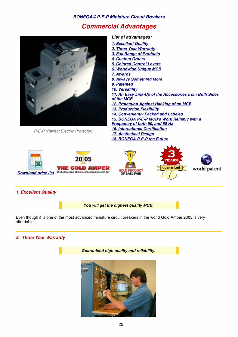
2. Three Year Warranty
P-E-P (Perfect Electric Protector)
List of advantages:
1. Excellent Quality
2. Three Year Warranty
3. Full Range of Products
4. Custom Orders
5. Colored Control Levers
6. Worldwide Unique MCB
7. Awards
8. Always Something More
9. Patented
10. Versatility
11. An Easy Link-Up of the Accessories from Both Sidesof the MCB
12. Protection Against Hacking of an MCB
13. Production Flexibility
14. Conveniently Packed and Labeled
15. BONEGA P-E-P MCB's Work Reliably with aFrequency of both 50, and 60 Hz
16. International Certification
17. Aesthetical Design
18. BONEGA P-E-P the Future
Download price list
You will get the highest quality MCB.
Guaranteed high quality and reliability.
25

3. Full Range of Products
The entire conception for individual combinations is based on the production of just single-module MCB´s fromwhich it is possible to form any combinations, e.g. 1P (pole), 2P, 3P, 4P, 1P+N (zero = switch), 3P+N. All thecombinations are available both with the curve B,C, and D.
It is possible to produce the values from 0,5 up to 63A (in any ampere value, i.e. scale even with only 1 A).
They have been designed for alternative current (AC), but can be used for direct current (DC)*.* Contact technical support.
Our superior quality DC MCB's are available by special order. Contact us for more details.
4. Custom Orders
We can tailor make your order.
5. Colored Control Levers
We supply both colored levers and black levers in accordance with the nominal current values (corresponding to themarking of turn fuses).
6. Worldwide Unique MCB
No MCB has such excellent parameters with so many advantages.
We are leading the way in MCB future technology.
The unique resistant construction and careful product control ensure errorfree use backed by our three year warranty.
All combinations as well as special types.
Custom orders at a competitive price.
The colored levers improve the transparency and comply with therequirements of power plants.
0,2 A - 1,6 A black2 A pink4 A brown6 A green8 A light green
10 A red13 A sandy
16 A grey20 A blue25 A yellow32 A purple40 A black50 A white63 A copper-coloured
One of the most outstanding MCB's in the world.
26

7. Awards
� MCB's BONEGA P-E-P was awarded the Gold Amper and has become the best product of the mostprestigious Czech Fair AMPER 2005.
� MCB's BONEGA P-E-P was awarded (The Gold Product) at the BAEL FAIR 2004.
8. Always Something More
Compare our miniature circuit breaker with any other MCB of the same category. You can find always somethingmore with the MCB BONEGA® P-E-P.
9. Patented
10. Versatility
The height of the MCB terminals corresponds to other electrical devices BONEGA® , such as current protectors,modular switches etc. the mutual interconnection enables to form combined devices.
For example, the combination of the MCB 1P + N along with a double-pole protective switch or the MCB 3P + Nalong with a four-pole current protective switches (see protective switches ). This interconnection can be reachedeasily by means of a 2P or 4P interconnecting strip (see accessories to the MCB´s).
The awards prove the exceptional capacityof the MCB´s BONEGA P-E-P.
Compare our products.
The BONEGA P-E-P MCB's are patent-protected.
Our MCB's are patent-protected.
The whole MCB is also protected as anindustrial design.
No need to buy any expensive combined deviceselsewhere.
27

11. An Easy Link-Up of the Accessories from Both Sides of the MCB
The numerous accessories can be linked-up from both sides of the MCB. The interconnection with the MCB is doneas follows:
1. Remove the grey self-adhesive plate, which covers the interconnecting pole on the left or right side (with nailor screwdriver) in accordance with the type of the accessories.
2. Set up the MCB into the OFF position.
3. With an easy “snapping” into place without any tools, connect the accessories to the MCB.
The miniature circuit breakers are compatible with the accessories of one of the best producers in Europe: MERLIN– GERIN.
Their system includes low-volt releases, ejecting coils, auxiliary contacts, etc. All those elements extend theapplication of the MCB by overvoltage or undervoltage protection, control, regulation, remote control, remoteindication of switch-on and switch-off positions of the circuit breaker, programming and measurement. Thosecombinations enable the circuit breakers to be applied in the range of control of the complicated automatedprocesses.
These elements can be mutually interconnected (e.g. MCB + undervoltage release + auxiliary indicating contactetc.), thus they can form different combinations.
See our offer accessories for the MCB's.
12. Protection Against Hacking of an MCB
The multi-pole MCB´s BONEGA P-E-P cannot be disassembled in such a way that only the interconnection betweenstretching levers would be removed and the individual poles could function separately (e.g. through this, the day andnight tariff rate could be influenced). Especially the distribution companies call for this property.
The mutual phases interconnection does not happen just between the levers, but also by means of pins which areput between the pole and they interfere directly into the inside mechanisms through a side hole. In addition, themulti-pole design is connected with rivets. The interconnecting and covering strip, which is between the levers, isvisibly depreciated.
Any interference in a MCB is obvious at first sight.
A fast connection of the accessories.
We comply with the requirements of distributioncompanies for disassembly protection.
28

13. Production Flexibility
Production is flexible and special types are made upon request, usually within 48 hours.
14. Conveniently Packed and Labeled
The cases are intended for 12 modules so there are either 12 pcs. single-pole MCB's, 6 pcs. two-poles MCB's, 4pcs. three-pole MCB's or three pcs. four-pole MCB's in one case (total weight of circuit breakers in one caseamounts to approx. 1,3 kg).
» Exact weights are at www.bonega.cz
One side of the case, there is a label put on, describing especially the type, curve, nominal current value andnumber of pieces.
If there are more types in one case, types and number of pieces are marked on the label to be addedmanually, when packing. We are sure you will appreciate this type of packing not only on collection of the deliveredgoods, but also on job site.
15. BONEGA P-E-P MCB's Work Reliably with a Frequency of Both 50 and 60 Hz
The change of frequency has no influence on the MCB function.
We will reply to special requests within 48 hours.
MCB's come in an easy access case.
Suitable for US.
29

16. International Certification
Thanks to the successful CB test, which is valid in 46 countries worldwide, the approval procedure for our MCB'sand their industrial installation can be accelerated significantly.
17. Aesthetically Designed
Because of its aesthetic appearance, they'll fit together with the modern switchboard.
18. BONEGA P-E-P ... the Future
BONEGA P-E-P's planned products:
� module switchers� current protectors� DPN (1P+N) up to 40 A (a switcher and MCB associated at one module with the width of 17 mm) – because
of the snap chamber and switching-off mechanism we expect the short-circuit resistance of 6 kA to bereached (the products with the short-circuit resistance of only up to 4 kA are known over the world)
� module contactors� current protector and MCB (associated in two modules – 2 x 17 mm)� DPN + current protector in two modules (2 x 17 mm)� module series of MCB´s from 60 A to 125 A
(contact: center 6)
Sales Department: - paní Libuše Možnarová, tel. /fax 518 335 216, email : [email protected], 696 66 Sudom��ice nad Moravou302Secretary of the Company: ing. Roman Hude�ek 603 542 347, [email protected]
Sale abroad is even easier.
Modern round shapes.
On the horizon.
30

Miniature Circuit Breakers BONEGA® P-E-P
As to the available information, because of their extraordinary short dimensions (especially the width of only 81 mm),our P-E-P MCB´s are classified as among the smallest MCB´s over the world in the category of short-circuitresistance up to 10 kA. In the category of 15 kA, we have the shortest dimensions worldwide (see the dimensionedchart).
� total height from the pawl incl. lever at switched-off position 72,23 mm� total height from the DIN strip incl. lever at switched-off position 67,23 mm� total height from the DIN strip up to the surface is 61,6 mm� total height from the DIN strip up to the surface of terminals is 43,8 mm� total width is 81 mm + 5,2 mm� width of controlling part 45 mm� distance between the upper supporting part of the terminal and the DIN strip 19,0 mm� distance between the supporting part of the terminal for placing the forked interconnecting strip and the DIN
strip is 33,0 mm� module width 17,6 mm� bottom assembly label – width 4,8 x 17,6 x 0,5 mm� upper users´ label – width 6,2 x 15,4 x 0,3 mm
Thus there is more space for conducting and connecting the conductors in the installation section which is coveredat a switchboard. This property can be appreciated especially when using these MCB´s at small apartmentswitchboards.
List of content:
1. Dimensioned chart
2. Charakteristics and application of ourMCB's
3. Technical data
4. Influence of ambient temperature onnominal currents
1. DIMENSIONED CHART
31

The limiting miniature circuit breakers BONEGA® P-E-P-15J have two different releases acting onto the switchingmechanism:
They are thus intended to protect the electrical distribution systems and electrical devices against short-circuit (if the defect has been caused by failure or incorrect connection) and to protect the electrical distributionsystem against overload (if the circuit has not been damaged but an extreme thermal overload occurred whichcould damaged the wiring).
They are suitable especially for common installation into switchboards and switching points of low-voltage endcircuits. They are designed mostly for alternating current but they can be used also for direct current for whichthe reduction of short-circuit resistance by approx. about 20% has to be taken into account (because of a higherstress of contacts).
With their design and technical parameters, the miniature circuit breakers BONEGA® P-E-P-15J conform to thecurrent technical top level world-wide.
They are marked with a logo with a trademark BONEGA®. It is a traditional brand since 1992 which shall beintroduced to the markets over the world. The name BONEGA comes from the ESPERANTO language and in thatlanguage, Bonega means excellent, good.
The name of the P-E-P series conceals the English term Perfect Electric Protector, stressing its extraordinary highquality supported by a long guarantee).
The miniature circuit breakers are manufactured in accordance with a particular European standard CSN EN60898, as amended. They are able to comply with any design requirements for arrangement of MCB´s with regardto the selectivity and requirements for individual characteristics B, C and D.
The MCB´s BONEGA® , series P-E-P have more than 50 user's advantages
The miniature circuit breakers BONEGA® , series P-E-P, can be mutually interconnected by means of single-pole to four-poles interconnecting forked and reed (rack) strips.
The miniature circuit breakers BONEGA® , series P-E-P, enable the plentiful accessories of one of the bestproducers in Europe, MERLIN – GERIN to be linked very easily. This system includes inter alia low-volt releases,voltage releases, ejecting coils, auxiliary contacts etc. All those elements provide protection, easy control,regulation, and remote control, remote indication of switch-on and switch-off positions of the circuit breaker,programming and measurement. By means of what has been mentioned above, those elements enable our circuitbreakers to be applied in the range of control automatization of different industrial processes. These elements canbe mutually interconnected as well, thus they can form different combinations to get thorough operationalinformation.
2. CHARACTERISTICS AND APPLICATION OF OUR MCB'S
1.) thermal over-current release for over-current protection,working with time lag
2.) electromagnetic high-speed release with ejecting armaturefor immediate short-circuit protection
- the product has received the certificate of the Electrotechnical Testing Institute of the CzechRepublic
- the product complies with the conditions necessary for evaluation if our product conforms to theCzech rules
CB TEST - the product has fulfilled the European conditions for application thereof
- the product complies with the European conditions for Declaration on Conformity
- the product has received a prestigious SEMCO Certificate
32

3. TECHNICAL DATA
Technical dataNumber of poles: 1,2,3,4, 1+N,3+N
Nominal currents ln (A): 1,2,3,4,6,10,13,16,20,25,32,40,50,63Characteristics: B (or L), also “V” before. The short-circuit release is to be set up to 3 ln through 5 ln. It
serves especially for protection of circuits with such devices which do not cause anycurrent surges (lights or socket circuits etc.)C (or U), also K before. The short-circuit release is to be set up to 5 ln through 10 ln. Itserves especially for protection of circuits with such devices which cause some currentsurges (groups of bulbs, motors etc.)D (or M), also „---------„ before. The short-circuit release is to be set up to 10 In through20 In. It serves especially for protection of circuit with devices which cause high currentsurges (transformers, double-pole motors, motors with heavy start etc.)
Nominal voltage: 1 P (single-pole) ~ 230/400 V 50/60 Hz3 P (three-pole) ~ 400 V 50/60 Hz
Rupturing capacity: EN 60898 - 15.000 A (nominal short-circuit and operational rupturing capacity)Protection: IP 20 for a sole MCB - with its design, it protects against a hazardous finger touch as
well as against small foreign objects; it is without any protection against water leakage( water protection is to be solved with design of the switchboard casing )IP 40 for a sole MCB - with its design, it protects against a hazardous finger orinstrument touch as well as against very small foreign objects; it is without anyprotection against water leakage ( water protection is to be solved with design of theswitchboard casing )
Ambient temperature: - 5 ºC to +40 ºC pursuant to �SN EN 60898Gauging temperature: +30 ºC pursuant to CSN (it is possible to agree upon different temperature)Max. pre-inserted fuse: 100 A gG (>10 kA)Mechanical lifetime: >= 20.000 cyclesElectrical lifetime: >= 8.000 cyclesOperational position: arbitraryFastening: by means of an unique snap mechanism (with arrestment in final positions) the
carrying DIN strip EN 50022, width 35 mm, or even onto the flat surface by means ofscrews
Removal from the DINstrip
by means of an unique auxiliary snap mechanism; the MCB´s can be removed evenfrom a row of devices mutually interconnected by a forked or reed (rack) strip withoutnecessity to dismantle the whole interconnecting strip
Input terminals: - clip terminals (with barrier layer), snap- locked against the worse input of a conductor- the input and output can be interchanged- they enable more conductors as well as interconnecting strips to be connected
Connectability ofconductors (maximumcross-sections):
35 mm2 solid conductor, 25 mm2 stranded conductor
Terminal protection: IP 20Tightening moment forterminals::
2 Nm (combined slotted-head screw)
Manufactured accordingto the standard:
�SN EN 60898
Power limiting class 3Switch-off speed (seeoscilograms):
under 5 ms
33

(contact: center 6)
Sales Department: - paní Libuše Možnarová, tel. /fax 518 335 216, email : [email protected], 696 66 Sudom��ice nadMoravou 302Secretary of the Company: ing. Roman Hude�ek 603 542 347, [email protected]
Coloured levers:
For better distinction among circuits in the switchboards, wesupply also miniature circuit breakers with distinction of nominalcurrents by means of colored levers corresponding to thecolours of turn fuses:
0,2 A - 1,6 A black2 A pink4 A brown6 A green8 A light green10 A red13 A sandy16 A grey20 A blue25 A yellow32 A purple40 A black50 A white63 A copper-coloured
Can be delivered also with only black levers 1-63 A black
4. INFLUENCE OF AMBIENT TEMPERATURE ON NOMINAL CURRENTS
Influence of ambient temperature on nominal currents of the MCB´s BONEGA® P-E-P-15J
Nominalcurrent ofMCB ( A )
Internalresistance
(mOhm)
Powerloss(W)
Max.impedanceof impedance loop
(Ohm)Thermal correction of nominal currents
Char.
B
Char.C
Char.D
Ambienttemp.20OC
Ambienttemp.30OC
Ambienttemp.40OC
Ambienttemp.50OC
Ambienttemp.60OC
1 1215,69 1,24 46,20 25,70 14,40 1,05 1 0,95 0,90 0,852 343,28 1,38 21,60 12,02 6,73 2,08 2 1,92 1,84 1,743 128,09 1,15 16,90 9,40 5,26 3,18 3 2,82 2,61 2,374 105,53 1,68 10,68 5,94 3,33 4,24 4 3,76 3,52 3,246 29,22 1,08 7,14 3,97 2,22 6,24 6 5,76 5,52 5,3010 14,49 1,55 3,87 2,15 1,21 10,60 10 9,30 8,60 7,8016 10,00 2,56 2,24 1,25 0,70 16,80 16 15,20 14,20 13,3020 8,02 3,32 1,55 0,86 0,48 21,00 20 19,00 17,80 16,8025 3,11 2,00 2,43 1,35 0,76 26,20 25 23,70 22,20 20,7032 3,05 3,17 1,27 0,71 0,40 33,50 32 30,40 28,40 27,5040 2,16 3,40 0,60 0,33 0,19 42,00 40 38,00 35,60 33,2050 1,65 4,20 0,71 0,39 0,22 52,50 50 47,40 44,00 40,5063 1,68 6,30 0,47 0,26 0,15 66,20 63 58,00 54,20 49,20
34