MCAMX5 Quick Ref Card
6
Create your own keyboard shortcuts. Choose Settings > Key mapping. • Save sets of shortcuts to different key map files (.KMP). • Open .KMP files in any text editor. Change toolbar layouts. Choose Settings > Customize. • Name sets of toolbars and save them to different toolbar files (.MTB). • Choose Toolbar States to hide or display toolbars. Customize the right-click menu. Choose Settings > Customize > Dropdowns/ Right mouse button to add your own functions (.MTB file). Use drop-down menus. Choose Settings > Customize > Drop- downs tab to add drop- down menus to toolbars. QUICK REFERENCE CARD Icon Icon Customizing Mastercam Function Keyboard Shortcut Analyze entities F4 AutoSave Alt+A C-Hook or user app Alt+C Configure Mastercam Alt+F8 Copy to clipboard Ctrl+C Cut to clipboard Ctrl+X Delete entities F5 Drafting global options Alt+D Exit Mastercam Alt+F4 Fit geometry to screen Alt+F1 Gview–Back Alt+3 Gview–Bottom Alt+4 Gview–Front Alt+2 Gview–Isometric Alt+7 Gview–Left Alt+6 Gview–Previous Alt+P Gview–Right Alt+5 Gview–Top Alt+1 Help Alt+H Hide entities Alt+E Level Manager Alt+Z Main attributes, set from entity Alt+X Function Keyboard Shortcut Mastercam version, SIM serial number Alt+V Motion controller rotation point Alt+F12 Pan Arrow keys Paste from clipboard Ctrl+V Previous view Alt+P Redo an event that has been undone Ctrl+Y Regenerate screen Shift+Ctrl+R Repaint F3 Rotate Alt+Arrow keys Select all Ctrl+A Selection grid options Alt+G Shading on/off Alt+S Show/hide all axes (WCS, Cplane, Tplane) Alt+F9 Show/hide coordinate axes F9 Show/hide displayed toolpaths Alt+T Show/hide Operations Manager pane Alt+O Undo the last creation or event Alt+U, Ctrl+U, Ctrl+Z Unzoom to 80% of original Alt+F2 Unzoom to previous or 50% of original F2 Zoom around target point Ctrl+F1 Zoom with window selection F1 Zoom/unzoom by 5% Page Up, Page Down
Transcript of MCAMX5 Quick Ref Card
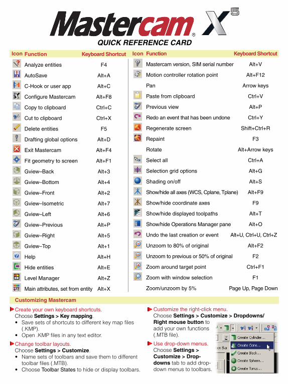
Create your own keyboard shortcuts.Choose Settings > Key mapping.• Savesetsofshortcutstodifferentkeymapfiles
(.KMP). • Open.KMPfilesinanytexteditor.
Change toolbar layouts.Choose Settings > Customize.• Namesetsoftoolbarsandsavethemtodifferent
toolbarfiles(.MTB).• ChooseToolbar Statestohideordisplaytoolbars.
Customize the right-click menu.Choose Settings > Customize > Dropdowns/Right mouse buttontoaddyourownfunctions(.MTBfile).
Use drop-down menus.Choose Settings > Customize > Drop-downs tabtoadddrop-downmenustotoolbars.
QUICK REFERENCE CARDIconIcon
Customizing Mastercam
Function Keyboard Shortcut
Analyze entities F4
AutoSave Alt+A
C-Hook or user app Alt+C
Configure Mastercam Alt+F8
Copy to clipboard Ctrl+C
Cut to clipboard Ctrl+X
Delete entities F5
Drafting global options Alt+D
Exit Mastercam Alt+F4
Fit geometry to screen Alt+F1
Gview–Back Alt+3
Gview–Bottom Alt+4
Gview–Front Alt+2
Gview–Isometric Alt+7
Gview–Left Alt+6
Gview–Previous Alt+P
Gview–Right Alt+5
Gview–Top Alt+1
Help Alt+H
Hide entities Alt+E
Level Manager Alt+Z
Main attributes, set from entity Alt+X
Function Keyboard Shortcut
Mastercam version, SIM serial number Alt+V
Motion controller rotation point Alt+F12
Pan Arrow keys
Paste from clipboard Ctrl+V
Previous view Alt+P
Redo an event that has been undone Ctrl+Y
Regenerate screen Shift+Ctrl+R
Repaint F3
Rotate Alt+Arrow keys
Select all Ctrl+A
Selection grid options Alt+G
Shading on/off Alt+S
Show/hide all axes (WCS, Cplane, Tplane) Alt+F9
Show/hide coordinate axes F9
Show/hide displayed toolpaths Alt+T
Show/hide Operations Manager pane Alt+O
Undo the last creation or event Alt+U, Ctrl+U, Ctrl+Z
Unzoom to 80% of original Alt+F2
Unzoom to previous or 50% of original F2
Zoom around target point Ctrl+F1
Zoom with window selection F1
Zoom/unzoom by 5% Page Up, Page Down
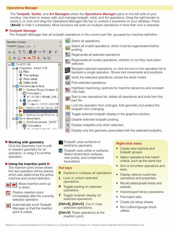
Operations Manager
Using the insertion pointThe insertion point shows where the next operation will be placed, which also determines the active machine and control definition.
Working with geometryClick the Geometry icon to edit or reselect geometry for an operation, or drag it to another operation.
Toolpath uses surfaces or wireframe geometry.
Toolpath uses solids or surfaces. Select drive/check surfaces, start points, and containment boundaries.
Hot keys
E Expand or collapse all operations.
L Lock or unlock selected operations.
P Toggle posting on selected operations.
T Toggle toolpath display for selected operations.
[Ctrl+X], [Ctrl+C] Cut or copy selected operations.
[Ctrl+V] Paste operations at the insertion point.
Right-click menu
• Createnewmachineandtoolpath groups.
• Selectoperationsthatmatchcriteria, such as the same tool.
• Sortorrenumberoperationsandtools.
• Displayoptionscustomizeoperations and properties.
• Recalculate/updatefeedsandspeeds.
• Import/exportlibraryoperations.
• Postbatchjobs.
• Createjobsetupsheets.
• Runcollision/gougecheckutilities.
Select all operations.
Select all invalid operations, which must be regenerated before posting.
Regenerateallselectedoperations.
Regenerateallinvalidoperations,whetherornottheyhavebeenselected.
Backplot selected operations, or click the icon in the operation list to backplot a single operation. Shows tool movements and positions.
Verify the selected operations; shows the stock model.
Post selected operations.
Highfeedmachining;optimizeformachinedynamicsandconstantchip load.
Start a new operations list; delete all operations and tools from the part file.
Lock the operation from changes. Edit geometry but protect the toolpath from changing.
Toggle selected toolpath display in the graphics window.
Disableselectedtoolpathposting.
Displaytoolpathsonlywhenselected.
Displayonlythegeometryassociatedwiththeselectedtoolpaths.
Toolpath ManagerThe Toolpath Manager lists all toolpath operations in the current part file, grouped by machine definition.
Mastercam is a registered trademark of CNC Software, Inc. © Copyright 2010 CNC Software, Inc. All rights reserved. September 2010 X5-Quick Reference Card
The Toolpath, Solids, and Art Managers share the Operations Manager pane on the left side of your window.Usethemtoreview,edit,andmanagetoolpath,solid,andArtoperations.Dragtherightbordertoresizeit,orclickanddragtheOperationsManagertitlebartoundockitanywhereonyourdesktop.Press[Alt+O] to hide it completely. Most functions will work on multiple operations if more than one is selected.
Move insertion point up or down.
Position insertion point immediately after the currently selected operation.
Automatically scroll Toolpath Manager so that the insertion point is visible.
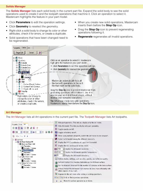
Solids Manager
The Solids Manager lists each solid body in the current part file. Expand the solid body to see the solid operations used to create it and the toolpath operations that machine it. Click an operation to select it. Mastercam highlights the feature in your part model.
• Whenyoucreatenewsolidoperations,Mastercaminserts them before the Stop Op icon.
• DragtheStop Op icon to prevent regenerating operationsfollowingit.
• Regenerate regenerates all invalid operations.
• Click Parameters to edit the operation settings.
• ClickGeometry to reselect the geometry.
• Right-clickasolidbodytochangeitscolororotherattributes,checkitforerrors,orcreateaduplicate.
• Solidoperationsthathavebeenchangedneedtobe regenerated.
Art Manager
The Art Manager lists all Art operations in the current part file. The Toolpath Manager lists Art toolpaths.
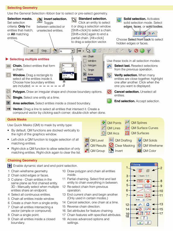
Selecting Geometry
Use the General Selection ribbon bar to select or pre-select geometry.
Selection masks. Set selection criteria: Only the entities that match, or All matching entities.
Solid selection. Activates solid selection mode. Select edges, faces, or solid bodies.
Standard selection. Click an entity to select
it or drag a selection window. [Shift+click] to select a chain. [Shift+click] again to end a partial chain. [Alt+click] to drag a selection vector.
Invert selection. Toggle
between selected or unselected entities.
Choose Select from back to select hidden edges or faces.
Chain. Select entities that form a chain.
Window. Drag a rectangle to select all the entities inside it. Choose how boundary entities are included.
Polygon. Draw an irregular shape and choose boundary options.
Single. Select one entity at a time.
Area selection. Select entities inside a closed boundary.
Vector. Drag a line to select all entities that intersect it. Create a compound vector by clicking each corner; double-click when done.
Selecting multiple entities
Select last. Reselect selections from the previous operation.
Verify selection. When many entities are close together, highlight one after another. Click when the one you want is displayed.
Cancel selection. Unselect all entities.
End selection. Accept selection.
Use these tools in all selection modes:
QM Points
QM Lines
QM Arcs
QM Splines
QM Surface Curves
QM Surfaces
QM Solids
QM Wireframe
QM Color
QM Level
QM Results
QM Group
QM Drafting
Clear Masking
Invert
1 Chain wireframe geometry.2 Chain solid edges or faces. 3 C-plane - Chain entities in the
same plane as first chained entity. 3D - Manually select when multiple entities share an endpoint.
4 Select all continuous entities.5 Chain all entities inside window. 6 Create a chain from a single entity. 7 Chain all entities intersecting a
vector (simple or compound).8 Chain a single point. 9 Chain all entities inside a closed
boundary.
Chaining Geometry
10 Draw polygon and chain all entities inside.
11 Partial chaining. Select first and last entity to chain everything in between.
12 Re-select chain from previous operation.
13 End current chain and begin another. (Only used in certain modes.)
14 Cancel selection, one chain at a time.15 Reverse chain direction. 16 Set attributes for feature chaining.17 Chain features with specified attributes.18 Access advanced options and
settings.
1 2
8
9
1011
13
1517
345
6
7
1214
1618
Quick Masks
Use Quick Masks (QM) to mask by entity type:
• Bydefault,QMfunctionsaredockedverticallytothe right of the graphics window.
• Left-clickaQMfunctiontotoggleselectionofallmatching entities.
• Right-clickaQMfunctiontoallowselectionofonlymatching entities. Right-click again to clear the list.
Enable dynamic start and end point selection.
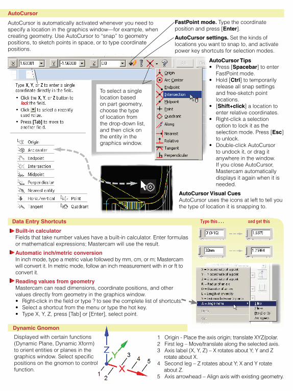
AutoCursor
AutoCursor is automatically activated whenever you need to specify a location in the graphics window—for example, when creating geometry. Use AutoCursor to “snap” to geometry positions, to sketch points in space, or to type coordinate positions.
FastPoint mode. Type the coordinate position and press [Enter].
AutoCursor settings. Set the kinds of locations you want to snap to, and activate power key shortcuts for selection modes.
To select a single location based on part geometry, choose the type of location from the drop-down list, and then click on the entity in the graphics window.
AutoCursor Tips• Press[Spacebar] to enter
FastPointmode.• Hold[Ctrl] to temporarily
release all snap settings and free-sketch point locations.
• [Shift+click] a location to enter relative coordinates.
• Right-clickaselectionoption to lock it as the selectionmode.Press[Esc] to unlock.
• Double-clickAutoCursorto undock it, or drag it anywhere in the window. If you close AutoCursor, Mastercam automatically displays it again when it is needed.
AutoCursor Visual CuesAutoCursor uses the icons at left to tell you the type of location it is snapping to.
Data Entry Shortcuts
Dynamic Gnomon
1Origin-Placetheaxisorigin;translateXYZ/polar.2Firstleg–Move/translatealongtheselectedaxis.3Axislabel(X,Y,Z)–XrotatesaboutY;YandZ
rotateaboutX.4Secondleg–ZrotatesaboutY;XandYrotate
aboutZ.5 Axis arrowhead – Align axis with existing geometry.
Displayedwithcertainfunctions(DynamicPlane,DynamicXform)to orient entities or planes in the graphics window. Select specific positions on the gnomon to control function.
Built-in calculatorFields that take number values have a built-in calculator. Enter formulas ormathematicalexpressions;Mastercamwillusetheresult.
Automatic inch/metric conversionIninchmode,typeametricvaluefollowedbymm,cm,orm;Mastercamwill convert it. In metric mode, follow an inch measurement with in or ft to convert it.
Reading values from geometryMastercam can read dimensions, coordinate positions, and other values directly from geometry in the graphics window. • Right-clickinthefieldortype?toseethecompletelistofshortcuts.• Selectashortcutfromthemenuortypethehotkey.• TypeX,Y,Z,press[Tab]or[Enter],selectpoint.
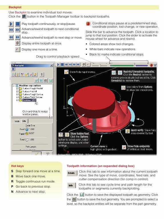
Toolpath information (on expanded dialog box)
Click this tab to see information about the current toolpath move. See the type of move, coordinates, feed rate, and cutter compensation direction (for comp in control).
Click this tab to see cycle time and path length for the toolpaths or segments currently backplotting.
Click the button to save the displayed toolpath as geometry. Click
the button to save the tool geometry. You are prompted to select a
level, so the backplot entities will be separate from the part geometry.
Backplot
Use Backplot to examine individual tool moves. Click the button in the Toolpath Manager toolbar to backplot toolpaths.
Play toolpath continuously, or stop/pause.
Advance/rewind toolpath to next conditional stop.
Advance/rewind toolpath to next step or move.
Display entire toolpath at once.
Display one move at a time.
Conditional stops pause at a predetermined step, coordinate position, tool change, or new operation.
Drag to control playback speed
Hot keys
S Step forward one move at a time.
B Move back one move.
R Toggle continuous run mode.
P Go back to previous stop.
N Advance to next stop.
Slide the bar to advance the toolpath. Click a location to jump to that tool position. Click the slider to activate the mouse wheel for advance and rewind.
• Coloredareasshowtoolchanges.
• Whitebarsindicatenewoperations.
• Blackticmarksindicateconditionalstops.