McAfee, Inc. McAfee Web Gateway WG5000 and WG5500 Appliances
32
McAfee, Inc. McAfee Web Gateway WG5000 and WG5500 Appliances Hardware Models: 5000, 5500; Firmware Version: 7.1.0 FIPS 140-2 Non-Proprietary Security Policy FIPS Security Level: 2 Document Version: 1.9 Prepared for: Prepared by: McAfee, Inc. Headquarters Corsec Security, Inc. 2821 Mission College Blvd. Santa Clara, CA 95054 USA 13135 Lee Jackson Memorial Highway, Suite 220 Fairfax, Virginia 22033 USA Phone: +1 (888) 847-8766 Phone: +1 (703) 267-6050 http://www.mcafee.com Email: [email protected]
Transcript of McAfee, Inc. McAfee Web Gateway WG5000 and WG5500 Appliances
McAfee, Inc.
McAfee Web Gateway WG5000 and WG5500 Appliances Hardware Models: 5000, 5500; Firmware Version: 7.1.0
FIPS 140-2 Non-Proprietary Security Policy
FIPS Security Level: 2
Document Version: 1.9
Prepared for: Prepared by:
McAfee, Inc. Headquarters Corsec Security, Inc.
2821 Mission College Blvd. Santa Clara, CA 95054
USA
13135 Lee Jackson Memorial Highway, Suite 220 Fairfax, Virginia 22033
USA
Phone: +1 (888) 847-8766 Phone: +1 (703) 267-6050 http://www.mcafee.com Email: [email protected]

Security Policy, Version 1.9 August 17, 2012
McAfee Web Gateway WG5000 and WG5500 Appliances Page 2 of 32
© 2012 McAfee, Inc. This document may be freely reproduced and distributed whole and intact including this copyright notice.
Table of Contents
1 INTRODUCTION ................................................................................................................... 4 1.1 PURPOSE ................................................................................................................................................................ 4 1.2 REFERENCES .......................................................................................................................................................... 4 1.3 DOCUMENT ORGANIZATION ............................................................................................................................ 4
2 MCAFEE WEB GATEWAY WG5000 AND WG5500 APPLIANCES ................................ 5 2.1 OVERVIEW ............................................................................................................................................................. 5 2.2 MODULE SPECIFICATION ..................................................................................................................................... 7 2.3 MODULE INTERFACES .......................................................................................................................................... 8 2.4 ROLES AND SERVICES ......................................................................................................................................... 12
2.4.1 Crypto-Officer Role.............................................................................................................................................. 12 2.4.2 User Role ................................................................................................................................................................ 12 2.4.3 Services ................................................................................................................................................................... 12 2.4.4 Unauthenticated Operator Services .............................................................................................................. 15 2.4.5 Authentication Mechanisms ............................................................................................................................. 15
2.5 PHYSICAL SECURITY ........................................................................................................................................... 16 2.6 OPERATIONAL ENVIRONMENT ......................................................................................................................... 16 2.7 CRYPTOGRAPHIC KEY MANAGEMENT ............................................................................................................ 17 2.8 EMI/EMC ............................................................................................................................................................ 20 2.9 SELF-TESTS .......................................................................................................................................................... 20
2.9.1 Power-Up Self-Tests ............................................................................................................................................ 20 2.9.2 Conditional Self-Tests ......................................................................................................................................... 21
2.10 MITIGATION OF OTHER ATTACKS .................................................................................................................. 21
3 SECURE OPERATION ......................................................................................................... 22 3.1 INITIAL SETUP ...................................................................................................................................................... 22
3.1.1 Setting FIPS Environment .................................................................................................................................. 22 3.1.2 Install the Opacity Baffles ................................................................................................................................. 23 3.1.3 Applying Tamper-Evident Seals ...................................................................................................................... 24 3.1.4 Power Supply Replacement .............................................................................................................................. 28
3.2 CRYPTO-OFFICER GUIDANCE .......................................................................................................................... 28 3.2.1 Management ........................................................................................................................................................ 29 3.2.2 Zeroization ............................................................................................................................................................ 29
3.3 USER GUIDANCE ................................................................................................................................................ 29
4 ACRONYMS .......................................................................................................................... 30
Table of Figures FIGURE 1 – MCAFEE WEB GATEWAY WG5000 (TOP) AND WG5500 (BOTTOM) ....................................................... 5 FIGURE 2 – TYPICAL DEPLOYMENT SCENARIO ..................................................................................................................... 6 FIGURE 3 – BLOCK DIAGRAM FOR THE WG 5000 AND WG 5500 .................................................................................. 8 FIGURE 4 – MCAFEE WEB GATEWAY 5000 (FRONT VIEW) ............................................................................................... 9 FIGURE 5 – MCAFEE WEB GATEWAY 5500 (FRONT VIEW) ............................................................................................... 9 FIGURE 6 – MCAFEE WEB GATEWAY 5000 (REAR VIEW) .................................................................................................. 9 FIGURE 7 – MCAFEE WEB GATEWAY WG5000 (REAR VIEW) ....................................................................................... 10 FIGURE 8 – OPACITY BAFFLE FOR WG5000...................................................................................................................... 23 FIGURE 9 – OPACITY BAFFLE INSTALLED ON WG5000 ................................................................................................... 23 FIGURE 10 – OPACITY BAFFLE FOR WG5500 ................................................................................................................... 23 FIGURE 11 – OPACITY BAFFLE INSTALLED ON WG5500 ................................................................................................. 24 FIGURE 12 – WG5000 FRONT BEZEL SEAL PLACEMENT (TOP)...................................................................................... 25 FIGURE 13 – WG5000 REMOVABLE PANEL SEAL PLACEMENT ........................................................................................ 25 FIGURE 14 – WG5000 FRONT BEZEL SEAL PLACEMENT (BOTTOM) ............................................................................. 26
Security Policy, Version 1.9 August 17, 2012
McAfee Web Gateway WG5000 and WG5500 Appliances Page 3 of 32
© 2012 McAfee, Inc. This document may be freely reproduced and distributed whole and intact including this copyright notice.
FIGURE 15 – WG5500 FRONT BEZEL SEAL PLACEMENT (TOP)...................................................................................... 26 FIGURE 16 – WG5500 REMOVABLE PANEL SEAL PLACEMENT ........................................................................................ 27 FIGURE 17 – WG5500 FRONT BEZEL SEAL PLACEMENT (BOTTOM) ............................................................................. 27 FIGURE 18 – WG5000 POWER SUPPLY SEALS PLACEMENT ............................................................................................. 28 FIGURE 19 – WG5500 POWER SUPPLY SEALS PLACEMENT ............................................................................................. 28
List of Tables............................................................................ TABLE 1 – MCAFEE WEB GATEWAY MODEL SPECIFICATIONS ........................................................................................... 7 TABLE 2 – SECURITY LEVEL PER FIPS 140-2 SECTION ......................................................................................................... 7 TABLE 3 – LED DESCRIPTIONS............................................................................................................................................. 10 TABLE 4 – MCAFEE WEB GATEWAY PORTS AND INTERFACES ....................................................................................... 11 TABLE 5 – FIPS 140-2 LOGICAL INTERFACE MAPPINGS ................................................................................................... 11 TABLE 6 – AUTHENTICATED SERVICES ................................................................................................................................ 12 TABLE 7 – UNAUTHENTICATED OPERATOR SERVICE ....................................................................................................... 15 TABLE 8 – AUTHENTICATION MECHANISMS EMPLOYED BY THE MODULE .................................................................... 16 TABLE 9 – ALGORITHM CERTIFICATE NUMBERS FOR CRYPTOGRAPHIC LIBRARIES ....................................................... 17 TABLE 10 – LIST OF CRYPTOGRAPHIC KEYS, CRYPTOGRAPHIC KEY COMPONENTS, AND CSPS .............................. 18 TABLE 11 – ACRONYMS ........................................................................................................................................................ 30

Security Policy, Version 1.9 August 17, 2012
McAfee Web Gateway WG5000 and WG5500 Appliances Page 4 of 32
© 2012 McAfee, Inc. This document may be freely reproduced and distributed whole and intact including this copyright notice.
1 Introduction
1.1 Purpose This is a non-proprietary Cryptographic Module Security Policy for the McAfee Web Gateway WG5000
and WG5500 Appliances from McAfee, Inc. This Security Policy describes how the McAfee Web
Gateway WG5000 and WG5500 Appliances meet the security requirements of Federal Information
Processing Standards (FIPS) Publication 140-2, which details the U.S. and Canadian Government
requirements for cryptographic modules. More information about the FIPS 140-2 standard and validation
program is available on the National Institute of Standards and Technology (NIST) and the
Communications Security Establishment Canada (CSEC) Cryptographic Module Validation Program
(CMVP) website at http://csrc.nist.gov/groups/STM/cmvp.
This document also describes how to run the module in a secure FIPS-Approved mode of operation. This
policy was prepared as part of the Level 2 FIPS 140-2 validation of the module. The McAfee Web
Gateway WG5000 and WG5500 Appliances are referred to in this document collectively as the McAfee
Web Gateway, the appliance, or the module.
1.2 References This document deals only with operations and capabilities of the module in the technical terms of a FIPS
140-2 cryptographic module security policy. More information is available on the module from the
following sources:
The McAfee corporate website (http://www.mcafee.com) contains information on the full line of
products from McAfee.
The CMVP website (http://csrc.nist.gov/groups/STM/cmvp/documents/140-1/140val-all.htm)
contains contact information for individuals to answer technical or sales-related questions for the
module.
1.3 Document Organization The Security Policy document is one document in a FIPS 140-2 Submission Package. In addition to this
document, the Submission Package contains:
Vendor Evidence document
Finite State Model document
Validation Submission Summary document
Other supporting documentation as additional references
This Security Policy and the other validation submission documentation were produced by Corsec Security,
Inc. under contract to McAfee. With the exception of this Non-Proprietary Security Policy, the FIPS 140-
2 Submission Package is proprietary to McAfee and is releasable only under appropriate non-disclosure
agreements. For access to these documents, please contact McAfee.

Security Policy, Version 1.9 August 17, 2012
McAfee Web Gateway WG5000 and WG5500 Appliances Page 5 of 32
© 2012 McAfee, Inc. This document may be freely reproduced and distributed whole and intact including this copyright notice.
2 McAfee Web Gateway WG5000 and WG5500 Appliances
2.1 Overview McAfee, Inc. is a global leader in Enterprise Security solutions. The company’s comprehensive portfolio
of network security products and solutions provides unmatched protection for the enterprise in the most
mission-critical and sensitive environments.
The McAfee Web Gateway is a high-performance, enterprise-strength proxy appliance family that provides
the caching, authentication, administration, and authorization controls required by today’s most demanding
enterprises. With multiple appliance models to choose from, the McAfee Web Gateway WG5000 and
WG5500 Appliances deliver deployment flexibility and performance, along with scalability to easily
support hundreds of thousands of users in a single environment. McAfee Web Gateway WG5000 and
WG5500 Appliances deliver comprehensive security for all aspects of Web 2.0 traffic. A front view of the
Model WG5000 and WG5500 is shown in Figure 1 below.
Figure 1 – McAfee Web Gateway WG5000 (top) and WG5500 (bottom)
The McAfee Web Gateway ensures comprehensive web security for networks. It protects networks against
threats arising from the web, such as viruses and other malware, inappropriate content, data leaks, and
related issues. It also ensures regulatory compliance and a productive work environment.
The appliance is installed as a gateway that connects a network to the web. Following the implemented
web security rules, it filters the requests that users send to the web from within the network. Responses
sent back from the web and embedded objects sent with requests or responses are also filtered. Malicious
and inappropriate content is blocked, while useful content is allowed to pass through.
Web filtering is accomplished via the following appliance processes:
Intercepting web traffic – This is achieved by the gateway functions of the appliance, using
different network protocols, such as HTTP1, HTTPS
2, FTP
3, Yahoo, ICQ, Windows Live
Messenger, and others. As a gateway, the appliance can run in explicit proxy mode or in
transparent bridge or router mode.
Filtering web objects – Special anti-virus and anti-malware functions on the appliance scan and
filter web traffic and block objects when they are infected. Other functions filter requested
URLs4, using information from the global TrustedSource intelligence system, or do media type
1 HTTP – Hypertext Transfer Protocol 2 HTTPS – Secure Hypertext Transfer Protocol 3 FTP – File Transfer Protocol 4 URL – Uniform Resource Locator

Security Policy, Version 1.9 August 17, 2012
McAfee Web Gateway WG5000 and WG5500 Appliances Page 6 of 32
© 2012 McAfee, Inc. This document may be freely reproduced and distributed whole and intact including this copyright notice.
and HTML5 filtering. They are supported by functions that do not filter themselves, but do such
jobs as counting user requests or indicating the progress made in downloading web objects.
Filtering users – This is done by the authentication mechanisms provided by the appliance, using
information from internal and external databases and methods such as NTLM6, LDAP
7,
RADIUS8, Kerberos, and others. In addition to filtering normal users, the appliance also provides
control over administrator rights and responsibilities.
Monitoring the filtering process – The monitoring functions of the appliance allow administrators
a continuous overview of the filtering process. They include a dashboard, providing information
on web usage, filtering activities, and system behavior, as well as logging and tracing functions
and options to forward data to an ePolicy Orchestrator or do event monitoring with an SNMP9
agent.
For user-initiated web requests, the McAfee Web Gateway first enforces an organization’s Internet use
policy. For all allowed traffic, it then uses local and global techniques to analyze the nature and intent of
all content and active code entering the network via the requested web pages, providing immediate
protection against malware and other hidden threats. Additionally, the SSL10
Scanner module of the
McAfee Web Gateway can examine SSL traffic to provide in-depth protection against malicious code that
has been disguised through encryption.
To secure outbound traffic, the McAfee Web Gateway scans user-generated content on all key web
protocols, including HTTP, HTTPS, and FTP. As part of a fully-integrated McAfee data loss prevention
solution, the McAfee Web Gateway protects against loss of confidential information and other threats
leaking from the organization through blogs, wikis, and online productivity tools such as organizers and
calendars.
The McAfee Web Gateway WG5000 and WG5500 Appliances also provide administrators with the ability
to monitor and troubleshoot the appliance.
The McAfee Web Gateway combines and integrates numerous protections that would otherwise require
multiple stand-alone products. Web filtering, anti-virus, anti-spyware, SSL scanning, and content control
filtering capabilities are combined into a single appliance. A simplified management footprint means that a
single security policy can be shared across protections and protocols. Figure 2 shows a typical deployment
scenario for the McAfee Web Gateway WG5000 and WG5500 Appliances.
Figure 2 – Typical Deployment Scenario
5 HTML – Hypertext Markup Language 6 NTLM – Microsoft Windows NT LAN Manager 7 LDAP – Lightweight Directory Access Protocol 8 RADIUS – Remote Authentication Dial-up User Service 9 SNMP – Simple Network Management Protocol 10 SSL – Secure Sockets Layer

Security Policy, Version 1.9 August 17, 2012
McAfee Web Gateway WG5000 and WG5500 Appliances Page 7 of 32
© 2012 McAfee, Inc. This document may be freely reproduced and distributed whole and intact including this copyright notice.
Table 1 below provides general specification for the McAfee Web Gateway WG5000 and WG5500
Appliances.
Table 1 – McAfee Web Gateway Model Specifications
WG5000 WG5500
Form Factor 1U rack-mount 2U rack-mount
Processor quad core 2 quad core
Memory 6 GB 12 GB
Interfaces 4 x 10/100/1000 4 x 10/100/1000
RAID RAID11 0/1/10 RAID 0/1/10
Hard Disk Available: 6 x 300 GB SAS
Installed : 2 x 300 GB SAS
Available: 8 x 300 GB SAS
Installed : 6 x 300 GB SAS
Power Supply Redundant Redundant
CPU Intel Xeon E5640 Intel Xeon E5660
The McAfee Web Gateway WG5000 and WG5500 Appliances are validated at the FIPS 140-2 Section
levels shown in Table 2 below.
Table 2 – Security Level Per FIPS 140-2 Section
Section Section Title Level
1 Cryptographic Module Specification 3
2 Cryptographic Module Ports and Interfaces 2
3 Roles, Services, and Authentication 2
4 Finite State Model 2
5 Physical Security 2
6 Operational Environment N/A
7 Cryptographic Key Management 2
8 EMI/EMC12 2
9 Self-tests 2
10 Design Assurance 3
11 Mitigation of Other Attacks N/A
2.2 Module Specification
The McAfee Web Gateway is a multi-chip standalone cryptographic hardware module that meets overall
Level 2 FIPS 140-2 requirements. The cryptographic boundary of the module is defined by the hard metal
11 RAID – Redundant Array of Inexpensive Disks 12 EMI/EMC – Electromagnetic Interference / Electromagnetic Compatibility

Security Policy, Version 1.9 August 17, 2012
McAfee Web Gateway WG5000 and WG5500 Appliances Page 8 of 32
© 2012 McAfee, Inc. This document may be freely reproduced and distributed whole and intact including this copyright notice.
chassis, which surrounds all the hardware and firmware components. Figure 3 13
depicts the block diagram
and the cryptographic boundary of the module, which is indicated using the red dotted line. Please note
that the anti-virus and URL categorization modules are excluded from the cryptographic boundary.
South Bridge
Network
Clock
Generator
CPU(s)
North Bridge
RAM
Cache
BIOS – Basic Input/Output System
CPU – Central Processing Unit
SATA – Serial Advanced Technology Attachment
SCSI – Small Computer System Interface
PCI – Peripheral Component Interconnect
HDD
Hardware
Management
Physical Cryptographic Boundary
External
Power Supply
Power
Interface
SCSI/SATA
Controller
PCIe – PCI express
HDD – Hard Disk Drive
DVD – Digital Video Disc
RAM – Random Access Memory
PCI/PCIe
Slots
DVD
Audio
USB
BIOS
PCI/PCIe
Slots
Graphics
Controller
KEY:
Serial
Figure 3 – Block Diagram for the WG 5000 and WG 5500
2.3 Module Interfaces
The McAfee Web Gateway is a multi-chip standalone cryptographic module that meets overall Level 2
FIPS 140-2 requirements. Interfaces on the module can be categorized as the following FIPS 140-2 logical
interfaces:
Data Input Interface
Data Output Interface
Control Input interface
Status Output Interface
Power Interface
13 It should be noted that either the serial port or the VGA port is used for status output but not both at the
same time.

Security Policy, Version 1.9 August 17, 2012
McAfee Web Gateway WG5000 and WG5500 Appliances Page 9 of 32
© 2012 McAfee, Inc. This document may be freely reproduced and distributed whole and intact including this copyright notice.
All ports and interfaces are located at the front or back side of the hardware module. The front of the
chassis is populated with the power/sleep, reset, ID14
, and NMI15
buttons and several LEDs16
; please note
that some of these are covered by the bezel. The front and rear view of the appliances are shown in the
figures below.
Figure 4 – McAfee Web Gateway 5000 (Front View)
Figure 5 – McAfee Web Gateway 5500 (Front View)
Figure 6 – McAfee Web Gateway 5000 (Rear View)
14 ID – Identification 15 NMI – Non- Maskable Interrupt 16 LED – Light-Emitting Diode
Security Policy, Version 1.9 August 17, 2012
McAfee Web Gateway WG5000 and WG5500 Appliances Page 10 of 32
© 2012 McAfee, Inc. This document may be freely reproduced and distributed whole and intact including this copyright notice.
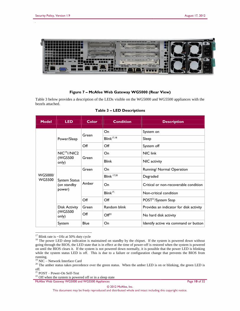
Figure 7 – McAfee Web Gateway WG5000 (Rear View)
Table 3 below provides a description of the LEDs visible on the WG5000 and WG5500 appliances with the
bezels attached.
Table 3 – LED Descriptions
Model LED Color Condition Description
WG5000/
WG5500
Power/Sleep Green
On System on
Blink17,18 Sleep
Off Off System off
NIC191/NIC2
(WG5500
only)
Green
On NIC link
Blink NIC activity
System Status
(on standby
power)
Green On Running/ Normal Operation
Blink 17,20 Degraded
Amber On Critical or non-recoverable condition
Blink17, Non-critical condition
Off Off POST21/System Stop
Disk Activity
(WG5500
only)
Green Random blink Provides an indicator for disk activity
Off Off22 No hard disk activity
System Blue On Identify active via command or button
17 Blink rate is ~1Hz at 50% duty cycle 18 The power LED sleep indication is maintained on standby by the chipset. If the system is powered down without
going through the BIOS, the LED state that is in effect at the time of power-off is restored when the system is powered
on until the BIOS clears it. If the system is not powered down normally, it is possible that the power LED is blinking
while the system status LED is off. This is due to a failure or configuration change that prevents the BIOS from
running. 19 NIC – Network Interface Card 20 The amber status takes precedence over the green status. When the amber LED is on or blinking, the green LED is
off. 21 POST – Power-On Self-Test 22 Off when the system is powered off or in a sleep state

Security Policy, Version 1.9 August 17, 2012
McAfee Web Gateway WG5000 and WG5500 Appliances Page 11 of 32
© 2012 McAfee, Inc. This document may be freely reproduced and distributed whole and intact including this copyright notice.
Model LED Color Condition Description
Identification Off Off No identification
Table 4 below describes the ports and interfaces found on the two models of the cryptographic module.
Table 4 – McAfee Web Gateway Ports and Interfaces
Model Physical Ports
Web Gateway WG5000 DVD-ROM Drive (covered by bezel)
Four (4) gigabit Ethernet ports
Four (4) Universal Serial Bus (USB) ports
One (1) serial port
One (1) Video Graphics Array (VGA) port
LEDs – ID, System Status, Power
Power/Sleep button, Reset button, ID button,
NMI button (covered by bezel)
Two (2) power connectors
Web Gateway WG5500 DVD-ROM Drive (covered by bezel)
Four (4) gigabit Ethernet ports
Four (4) Universal Serial Bus (USB) ports
Two (2) serial ports (one covered by bezel)
One (1) Video Graphics Array (VGA) port
LEDs – NIC 1, Power, System Status, ID, NIC
2, Hard Disk
Power/Sleep button, Reset button, ID button,
NMI button (covered by bezel)
Two (2) power connectors
Once the module has been mounted and applied with the tamper-evident seals by the Crypto-Officer, all
physical ports marked with “(covered by bezel)” will not be accessible unless the seals are broken by the
Crypto Officer. The Crypto-Officer role is defined in Section 2.4.1.
The module’s ports and interfaces are mapped to logical interfaces in Table 5 below. All of these physical
interfaces are separated into logical interfaces defined by FIPS 140-2, as described in Table 5.
Table 5 – FIPS 140-2 Logical Interface Mappings
FIPS 140-2 Interface McAfee Web Gateway WG5000 and WG5500
Appliances Physical Ports
Data Input Ethernet ports
Data Output Ethernet ports
Control Input Ethernet ports
Status Output Ethernet ports, serial port or VGA port, LEDs
Power Power connectors

Security Policy, Version 1.9 August 17, 2012
McAfee Web Gateway WG5000 and WG5500 Appliances Page 12 of 32
© 2012 McAfee, Inc. This document may be freely reproduced and distributed whole and intact including this copyright notice.
Status output will be provided via the serial port or the VGA port, dependant on the option selected during
installation of the V7.1.0 firmware.
2.4 Roles and Services
The module supports role-based authentication. There are two authorized roles in the module that an
operator may assume: a Crypto-Officer (CO) role and a User role.
2.4.1 Crypto-Officer Role
The Crypto-Officer (CO) role performs administrative services on the module, such as initialization,
configuration, and monitoring of the module. Before accessing the module for any administrative service,
the operator must authenticate to the module. The module offers the following management interfaces:
MWGUI23
SNMPv3
2.4.2 User Role
A User of the module is any one of a set of clustered modules that share configuration information of the
master McAfee Web Gateway appliance. Users have to authenticate to the module with a valid certificate
before they can access any of the user services.
2.4.3 Services
Services provided to authenticated operators are provided in Table 6 below. Please note that the keys and
Critical Security Parameters (CSPs) listed indicate the type of access required:
Read (R) : The CSP is read
Write (W): The CSP is established, generated, modified, or zeroized
Execute (X): The CSP is used within an Approved or Allowed security function or authentication
mechanism
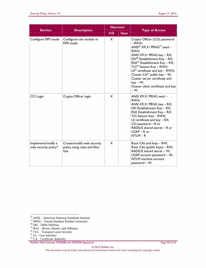
Table 6 – Authenticated Services
Service Description Operator
Type of Access CO User
Perform initial
configuration
Configure the primary
network interface, IP24
address, host name, and
DNS25 server
X None
23 MWGUI – McAfee Web Gateway Graphical User Interface 24 IP – Internet Protocol 25 DNS – Domain Name System
Security Policy, Version 1.9 August 17, 2012
McAfee Web Gateway WG5000 and WG5500 Appliances Page 13 of 32
© 2012 McAfee, Inc. This document may be freely reproduced and distributed whole and intact including this copyright notice.
Service Description Operator
Type of Access CO User
Configure FIPS mode Configures the module in
FIPS mode
X Crypto Officer (CO) password
– RWX;
ANSI26 X9.31 PRNG27 seed –
RWX;
ANSI X9.31 PRNG key – RX;
DH28 Establishment Key – RX;
RSA29 Establishment Key – RX;
TLS30 Session Key – RWX;
UI31 certificate and key – RWX;
Cluster CA32 public key – W;
Cluster server certificate and
key – W;
Cluster client certificate and key
– W
CO Login Crypto Officer login X ANSI X9.31 PRNG seed –
RWX;
ANSI X9.31 PRNG key – RX;
DH Establishment Key – RX;
RSA Establishment Key – RX;
TLS Session Key – RWX;
UI certificate and key – RX;
CO password – R or
RADIUS shared secret – R or
LDAP – R or
NTLM – R
Implement/modify a
web security policy*
Create/modify web security
policy using rules and filter
lists
X Root CAs and keys – RW;
Root CAs (public keys) – RW;
RADIUS shared secret – W;
LDAP account password – W;
NTLM machine account
password – W
26 ANSI – American National Standards Institute 27 PRNG – Pseudo Random Number Generator 28 DH – Diffie Hellman 29 RSA – Rivest, Shamir, and Adleman 30 TLS – Transport Layer Security 31 UI – User Interface 32 CA – Certificate Authority

Security Policy, Version 1.9 August 17, 2012
McAfee Web Gateway WG5000 and WG5500 Appliances Page 14 of 32
© 2012 McAfee, Inc. This document may be freely reproduced and distributed whole and intact including this copyright notice.
Service Description Operator
Type of Access CO User
Import a license* Import a license X None
Modify configuration
settings*
Modify appliance
configuration settings
X UI certificate and key – W;
Cluster CA public key – W;
Cluster server certificate and
key – W;
Cluster client certificate and key
– W;
WCCP33 authentication key –
W;
SNMP v3 passwords – W;
NTLM machine account
password – W
Manage administrator
account*
Set up account for
administrator
X CO password – W;
RADIUS shared secret – W;
NTLM machine account
password – W;
NTLM machine account
password – W
Backup appliance
configuration*
Store the appliance’s
configuration information
(including rules, lists, settings,
and administrator accounts)
in a backup file
X CO Password; SNMP v3
Password; RADIUS shared
secret; LDAP account
password; UI Certificate and
Key; Root CAs and keys; Root
CAs (public keys); WCCP key –
R
Restore appliance
configuration*
Restore the appliance’s
configuration information
from a backup file
X CO Password, SNMP v3
Password, RADIUS shared
secret, LDAP account
password, UI Certificate and
Key, Root CAs and keys, Root
CAs (public keys), WCCP key –
W
Monitor system
functions*
Monitor how the appliance
executes its filtering
functions
X None
Monitor status on
SNMP
Monitors non security
relevant status of the module
via SNMPv3
X SNMP v3 Password -Read
Perform self-tests* Run self-tests on demand (via
UI)
X None
Perform self-tests Run self-tests on demand (via
power cycle)
X None
33 WCCP – Web Cache Communication Protocol
Security Policy, Version 1.9 August 17, 2012
McAfee Web Gateway WG5000 and WG5500 Appliances Page 15 of 32
© 2012 McAfee, Inc. This document may be freely reproduced and distributed whole and intact including this copyright notice.
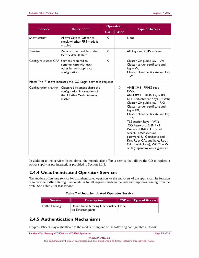
Service Description Operator
Type of Access CO User
Show status* Allows Crypto-Officer to
check whether FIPS mode is
enabled
X None
Zeroize Zeroizes the module to the
factory default state
X All Keys and CSPs – Erase
Configure cluster CA* Services required to
communicate with each
other in multi-appliance
configurations
X Cluster CA public key – W;
Cluster server certificate and
key – W;
Cluster client certificate and key
– W
Note: The ‘*’ above indicates the ‘CO Login’ service is required.
Configuration sharing Clustered instances share the
configuration information of
the McAfee Web Gateway
master
X ANSI X9.31 PRNG seed –
RWX;
ANSI X9.31 PRNG key – RX;
DH Establishment Keys – RWX;
Cluster CA public key – RX;
Cluster server certificate and
key – RX;
Cluster client certificate and key
– RX;
TLS session keys – WX;
CO Password, SNMP v3
Password, RADIUS shared
secret, LDAP account
password, UI Certificate and
Key, Root CAs and keys, Root
CAs (public keys), WCCP – W
or R (depending on originator)
In addition to the services listed above, the module also offers a service that allows the CO to replace a
power supply as per instructions provided in Section 3.1.3.
2.4.4 Unauthenticated Operator Services
The module offers one service for unauthenticated operators or the end-users of the appliance. Its function
is to provide traffic filtering functionalities for all requests made to the web and responses coming from the
web. See Table 7 for that service.
Table 7 – Unauthenticated Operator Service
Service Description CSP and Type of Access
Traffic filtering Utilize traffic filtering functionality
via Ethernet ports
None
2.4.5 Authentication Mechanisms
Crypto-Officers may authenticate to the module using one of the following configurable methods:
Security Policy, Version 1.9 August 17, 2012
McAfee Web Gateway WG5000 and WG5500 Appliances Page 16 of 32
© 2012 McAfee, Inc. This document may be freely reproduced and distributed whole and intact including this copyright notice.
NTLM
NTLM-Agent
LDAP
RADIUS
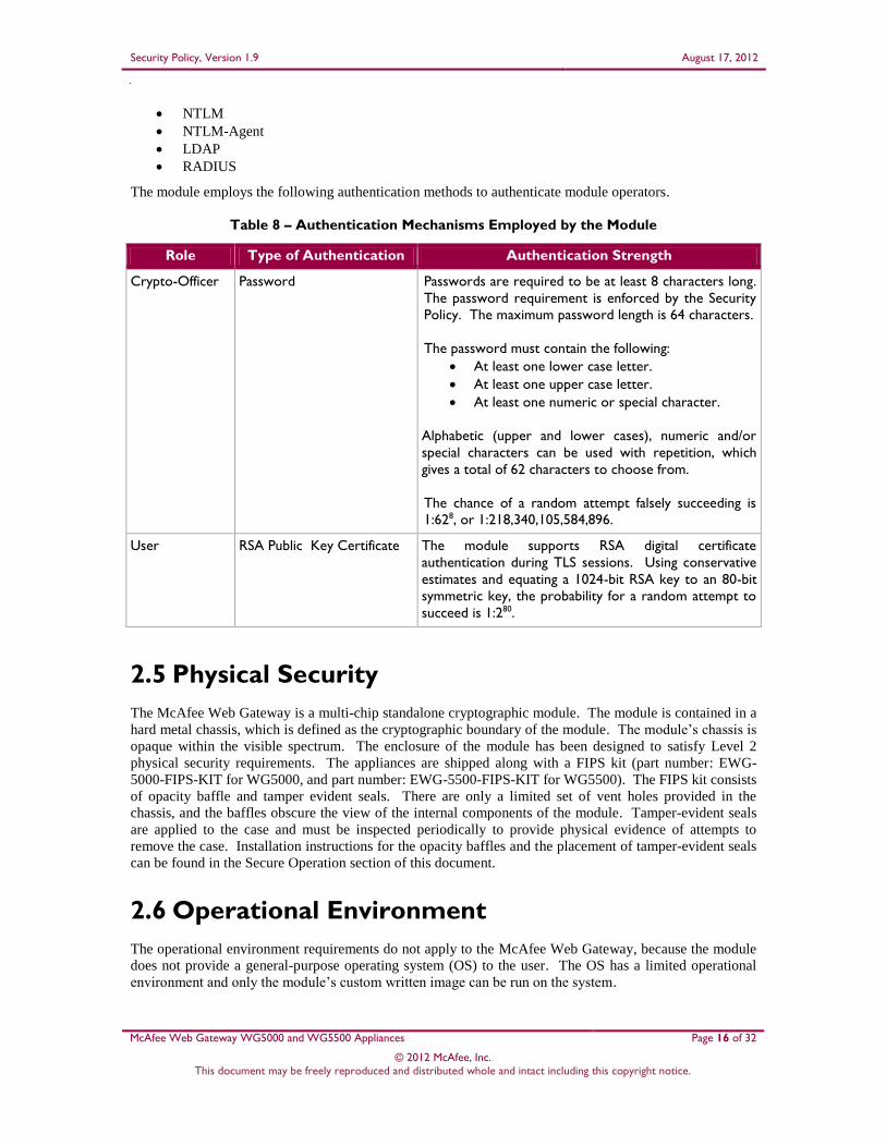
The module employs the following authentication methods to authenticate module operators.
Table 8 – Authentication Mechanisms Employed by the Module
Role Type of Authentication Authentication Strength
Crypto-Officer Password Passwords are required to be at least 8 characters long.
The password requirement is enforced by the Security
Policy. The maximum password length is 64 characters.
The password must contain the following:
At least one lower case letter.
At least one upper case letter.
At least one numeric or special character.
Alphabetic (upper and lower cases), numeric and/or
special characters can be used with repetition, which
gives a total of 62 characters to choose from.
The chance of a random attempt falsely succeeding is
1:628, or 1:218,340,105,584,896.
User RSA Public Key Certificate The module supports RSA digital certificate
authentication during TLS sessions. Using conservative
estimates and equating a 1024-bit RSA key to an 80-bit
symmetric key, the probability for a random attempt to
succeed is 1:280.
2.5 Physical Security
The McAfee Web Gateway is a multi-chip standalone cryptographic module. The module is contained in a
hard metal chassis, which is defined as the cryptographic boundary of the module. The module’s chassis is
opaque within the visible spectrum. The enclosure of the module has been designed to satisfy Level 2
physical security requirements. The appliances are shipped along with a FIPS kit (part number: EWG-
5000-FIPS-KIT for WG5000, and part number: EWG-5500-FIPS-KIT for WG5500). The FIPS kit consists
of opacity baffle and tamper evident seals. There are only a limited set of vent holes provided in the
chassis, and the baffles obscure the view of the internal components of the module. Tamper-evident seals
are applied to the case and must be inspected periodically to provide physical evidence of attempts to
remove the case. Installation instructions for the opacity baffles and the placement of tamper-evident seals
can be found in the Secure Operation section of this document.
2.6 Operational Environment
The operational environment requirements do not apply to the McAfee Web Gateway, because the module
does not provide a general-purpose operating system (OS) to the user. The OS has a limited operational
environment and only the module’s custom written image can be run on the system.
Security Policy, Version 1.9 August 17, 2012
McAfee Web Gateway WG5000 and WG5500 Appliances Page 17 of 32
© 2012 McAfee, Inc. This document may be freely reproduced and distributed whole and intact including this copyright notice.
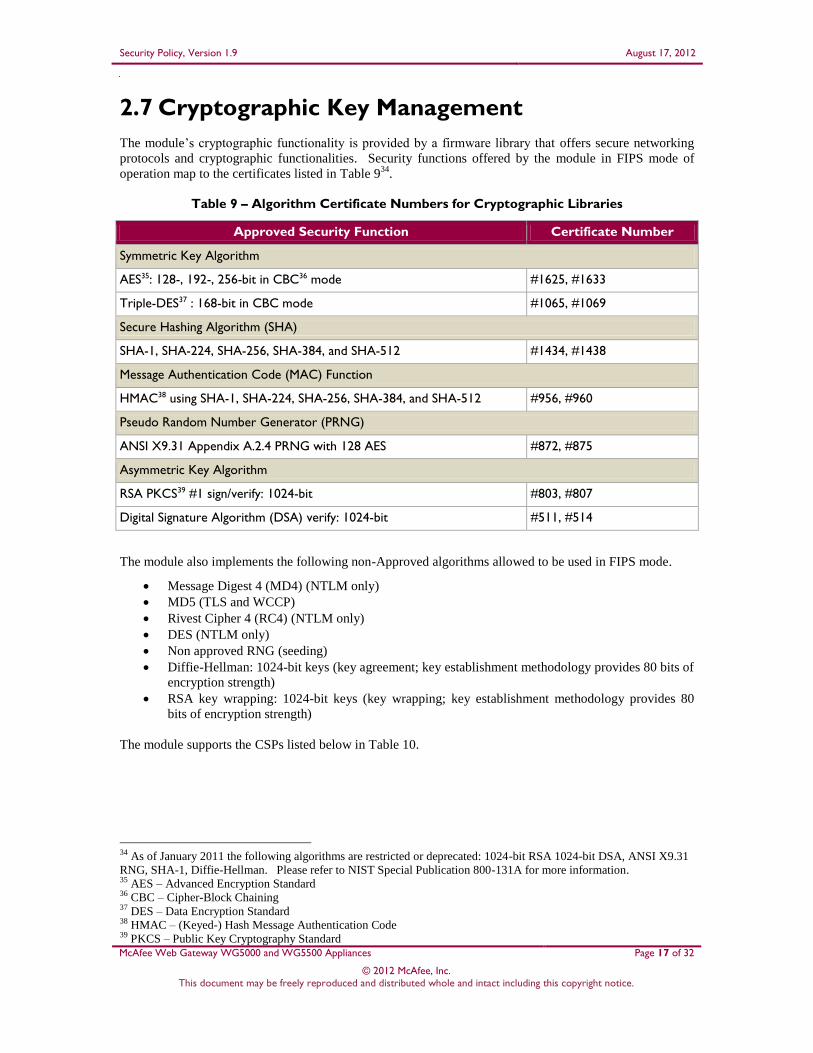
2.7 Cryptographic Key Management
The module’s cryptographic functionality is provided by a firmware library that offers secure networking
protocols and cryptographic functionalities. Security functions offered by the module in FIPS mode of
operation map to the certificates listed in Table 934
.
Table 9 – Algorithm Certificate Numbers for Cryptographic Libraries
Approved Security Function Certificate Number
Symmetric Key Algorithm
AES35: 128-, 192-, 256-bit in CBC36 mode #1625, #1633
Triple-DES37 : 168-bit in CBC mode #1065, #1069
Secure Hashing Algorithm (SHA)
SHA-1, SHA-224, SHA-256, SHA-384, and SHA-512 #1434, #1438
Message Authentication Code (MAC) Function
HMAC38 using SHA-1, SHA-224, SHA-256, SHA-384, and SHA-512 #956, #960
Pseudo Random Number Generator (PRNG)
ANSI X9.31 Appendix A.2.4 PRNG with 128 AES #872, #875
Asymmetric Key Algorithm
RSA PKCS39 #1 sign/verify: 1024-bit #803, #807
Digital Signature Algorithm (DSA) verify: 1024-bit #511, #514
The module also implements the following non-Approved algorithms allowed to be used in FIPS mode.
Message Digest 4 (MD4) (NTLM only)
MD5 (TLS and WCCP)
Rivest Cipher 4 (RC4) (NTLM only)
DES (NTLM only)
Non approved RNG (seeding)
Diffie-Hellman: 1024-bit keys (key agreement; key establishment methodology provides 80 bits of
encryption strength)
RSA key wrapping: 1024-bit keys (key wrapping; key establishment methodology provides 80
bits of encryption strength)
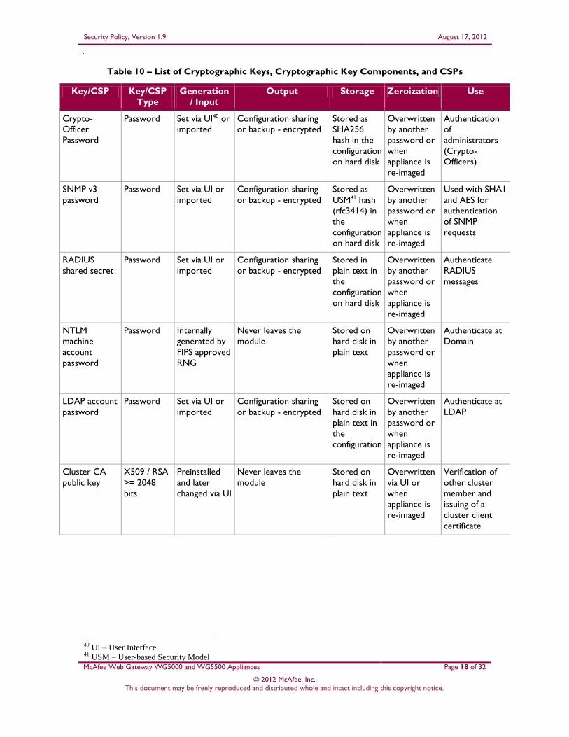
The module supports the CSPs listed below in Table 10.
34 As of January 2011 the following algorithms are restricted or deprecated: 1024-bit RSA 1024-bit DSA, ANSI X9.31
RNG, SHA-1, Diffie-Hellman. Please refer to NIST Special Publication 800-131A for more information. 35 AES – Advanced Encryption Standard 36 CBC – Cipher-Block Chaining 37 DES – Data Encryption Standard 38 HMAC – (Keyed-) Hash Message Authentication Code 39 PKCS – Public Key Cryptography Standard
Security Policy, Version 1.9 August 17, 2012
McAfee Web Gateway WG5000 and WG5500 Appliances Page 18 of 32
© 2012 McAfee, Inc. This document may be freely reproduced and distributed whole and intact including this copyright notice.
Table 10 – List of Cryptographic Keys, Cryptographic Key Components, and CSPs
Key/CSP Key/CSP
Type
Generation
/ Input
Output Storage Zeroization Use
Crypto-
Officer
Password
Password Set via UI40 or
imported
Configuration sharing
or backup - encrypted
Stored as
SHA256
hash in the
configuration
on hard disk
Overwritten
by another
password or
when
appliance is
re-imaged
Authentication
of
administrators
(Crypto-
Officers)
SNMP v3
password
Password Set via UI or
imported
Configuration sharing
or backup - encrypted
Stored as
USM41 hash
(rfc3414) in
the
configuration
on hard disk
Overwritten
by another
password or
when
appliance is
re-imaged
Used with SHA1
and AES for
authentication
of SNMP
requests
RADIUS
shared secret
Password Set via UI or
imported
Configuration sharing
or backup - encrypted
Stored in
plain text in
the
configuration
on hard disk
Overwritten
by another
password or
when
appliance is
re-imaged
Authenticate
RADIUS
messages
NTLM
machine
account
password
Password Internally
generated by
FIPS approved
RNG
Never leaves the
module
Stored on
hard disk in
plain text
Overwritten
by another
password or
when
appliance is
re-imaged
Authenticate at
Domain
LDAP account
password
Password Set via UI or
imported
Configuration sharing
or backup - encrypted
Stored on
hard disk in
plain text in
the
configuration
Overwritten
by another
password or
when
appliance is
re-imaged
Authenticate at
LDAP
Cluster CA
public key
X509 / RSA
>= 2048
bits
Preinstalled
and later
changed via UI
Never leaves the
module
Stored on
hard disk in
plain text
Overwritten
via UI or
when
appliance is
re-imaged
Verification of
other cluster
member and
issuing of a
cluster client
certificate
40 UI – User Interface 41 USM – User-based Security Model

Security Policy, Version 1.9 August 17, 2012
McAfee Web Gateway WG5000 and WG5500 Appliances Page 19 of 32
© 2012 McAfee, Inc. This document may be freely reproduced and distributed whole and intact including this copyright notice.
Key/CSP Key/CSP
Type
Generation
/ Input
Output Storage Zeroization Use
Cluster server
certificate and
key
X509 / RSA
with 1024
bits
Internally
generated by
FIPS approved
RNG
Private key will not
leave the module
Stored on
hard disk in
plain text or
in encrypted
form
(PKCS#8)
with
password
derived from
UUID42
Appliance re-
image or
reissuing due
to Cluster
CA change
Client / Server
authentication
for Transport
Layer Security
cluster
communication
Cluster client
certificate and
key
X509 / RSA
with 1024
bits
Internally
generated by
FIPS approved
RNG
Private key will not
leave the module
Stored on
hard disk in
plain text or
in encrypted
from
(PKCS8)
with
password
derived from
UUID
Appliance re-
image or
reissuing due
to Cluster
CA change
Client / Server
authentication
for TLS cluster
communication
UI certificate
and key
X509, RSA
with >=
1024 bits
Set via UI or
imported
Configuration sharing
or backup - encrypted
Stored in
plain text in
the
configuration
on hard disk
Overwritten
via UI or
when
appliance is
re-imaged
Serve TLS
connection to
the UI
Root CAs and
keys
X509, RSA
with >=
2048 bits
Set via UI or
imported
Configuration sharing
or backup - encrypted
Stored in
plain text in
the
configuration
file on hard
disk
Overwritten
via UI or
when
appliance is
re-imaged
SSL-Scanner:
Issuing server
certificates
Root CAs
(public keys)
X509, RSA
with >=
1024 bits
Set via UI or
imported
Configuration sharing
or backup - encrypted
Stored in
plain text in
the
configuration
on hard disk
Overwritten
via UI or
when
appliance is
re-imaged
SSL-Scanner:
Verification of
TLS connections
DH
Establishment
Keys
Diffie-
Hellman
1024 bit
Internally
generated by
FIPS approved
RNG
Never leaves the
module
Stored in
plain text on
hard disk
By power
cycle or
session
termination
TLS connections
for cluster
communication,
configuration,
signature
updates and SSL
Scanner
functions
42 UUID – Universally Unique Identifier

Security Policy, Version 1.9 August 17, 2012
McAfee Web Gateway WG5000 and WG5500 Appliances Page 20 of 32
© 2012 McAfee, Inc. This document may be freely reproduced and distributed whole and intact including this copyright notice.
Key/CSP Key/CSP
Type
Generation
/ Input
Output Storage Zeroization Use
RSA
Establishment
Keys
RSA key
transport
1024 bit
Internal taken
from
Certificate
Never leaves the
module
Stored in
plain text on
hard disk
By power
cycle or
session
termination
TLS connections
for UI or SSL
Scanner
TLS Session
key
3DES, AES
128, AES
256
Internally
generated by
FIPS approved
RNG
Never leaves the
module
Volatile
memory in
plain text
By power
cycle or
session
termination
TLS connections
for cluster
communication,
Configuration,
signature
updates and SSL
Scanner
functions
ANSI X9.31
PRNG seed
16 bytes of
seed value
Internally
generated by
non-approved
RNG
Never leaves the
module
Volatile
memory in
plain text
By power
cycle
Generates FIPS
approved
random number
used for
openSSL
ANSI X9.31
PRNG key
AES 128
Key
Internally
generated by
non-approved
RNG
Never leaves the
module
Volatile
memory in
plain text
By power
cycle
Generates FIPS
approved
random number
used for
openSSL
WCCP
authentication
key
Password Set via UI or
imported
Configuration sharing
or backup - encrypted
Stored in
plain text in
the
configuration
on hard disk
Overwritten
by another
password or
when
appliance is
re-imaged
Authentication
(MD5) for
WCCP UDP43
control packets
2.8 EMI/EMC
The McAfee Web Gateway system has been tested and found conformant to the EMI/EMC requirements
specified by 47 Code of Federal Regulations, Part 15, Subpart B, Unintentional Radiators, Digital Devices,
Class A (i.e., for business use).
2.9 Self-Tests The McAfee Web Gateway performs power-up and conditional self-tests as stated in the sections below.
2.9.1 Power-Up Self-Tests
The McAfee Web Gateway performs the following self-tests at power-up:
Firmware integrity check using MD5 Error Detection Code (EDC)
Approved algorithm tests
o AES Known Answer Test (KAT)
43 UDP – User Datagram Protocol

Security Policy, Version 1.9 August 17, 2012
McAfee Web Gateway WG5000 and WG5500 Appliances Page 21 of 32
© 2012 McAfee, Inc. This document may be freely reproduced and distributed whole and intact including this copyright notice.
o Triple-DES KAT
o SHA-1 KAT
o HMAC KAT with SHA-1, SHA-224, SHA-256, SHA-384, and SHA-512
o RSA KAT for sign/verify and encrypt/decrypt
o DSA pairwise consistency check
o ANSI X9.31 Appendix A.2.4 PRNG KAT
If any of the tests listed above fails to perform successfully, the module enters into a critical error state
where all cryptographic operations and output of any data is prohibited. Operators can reboot or power-
cycle the module, to try to clear the error and resume normal operation. If the error does not clear after a
reboot the appliance is unrecoverable.
2.9.2 Conditional Self-Tests
The module performs the following conditional self-tests:
Continuous PRNG Test (CRNGT)
RSA pairwise consistency test
DSA pairwise consistency test
Failure in any of the tests listed above leads the module to a conditional error. Conditional self-tests from
the User and CO services can lead to a conditional error, which is more easily recoverable than a critical
error. The conditional error can be cleared by rebooting or power-cycling the module. However, if the
error fails to clear, the module will go into a conditional error state again.
2.10 Mitigation of Other Attacks This section is not applicable. The module does not claim to mitigate any attacks beyond the FIPS 140-2
Level 2 requirements for this validation.

Security Policy, Version 1.9 August 17, 2012
McAfee Web Gateway WG5000 and WG5500 Appliances Page 22 of 32
© 2012 McAfee, Inc. This document may be freely reproduced and distributed whole and intact including this copyright notice.
3 Secure Operation
The McAfee Web Gateway WG5000 and WG5500 Appliances meet Level 2 requirements for FIPS 140-2.
The sections below describe how to place and keep the module in FIPS-Approved mode of operation.
3.1 Initial Setup The following sections provide the necessary step-by-step instructions necessary to configure the module
for FIPS Approved mode of operation. McAfee delivers the module via trusted delivery services (FedEx,
Expeditors International, and Airgroup Express). For any questions or issues that arise at any point during
the installation and configuration of the appliance, contact the McAfee support team at
http://www.mcafee.com/us/support.aspx .
3.1.1 Setting FIPS Environment
In order to setup the appliance in FIPS mode, the following steps will need to be performed by an
authorized individual:
1. Obtain version 7.1.0 installation image from McAfee extranet site.
2. Write 7.1.0 image to a USB or CD-ROM media.
3. From this point onwards until the appliance is sealed, the appliance must not be left unattended by
the operator.
4. Attach keyboard/monitor or serial console to appliance and boot to BIOS. Reset the BIOS setting
to their Default settings. Change boot settings to add USB or CD to top of boot order.
5. Reboot with media inserted.
6. Select the FIPS 140-2 level 2 installation mode and serial or keyboard/video as installation
operator interface.
7. Wait for disk reformat, install, and reboot.
8. Follow the procedures included in the Installation Guide to complete installation using the
installation wizard.
9. Follow the instructions in Section 3.2 to ensure that the appliance is completely configured for
FIPS mode of operation. Change the BIOS boot to be hard drive only and add an administrator
password to enter the BIOS
10. Power down the appliance and install the opacity baffles as per the instructions in Section 3.1.2.
11. Install the front bezel and apply tamper-evident seals as per the instructions in Section 3.1.2.
Power ON the appliance.
12. The appliance is now considered to be operating in a FIPS-Approved mode. Installation in this
mode disables logon to the appliance using SSH44
or from a console and implements other features
required for FIPS compliance. System output is displayed on a serial console.
After successful installation, the following needs to be done to maintain compliance:
1. The module should only boot from the hard drive while in FIPS mode.
2. The Intel Remote Management Console on the module is disabled by default and should remain so
when the module is being operated in FIPS mode.
3. The log file encryption and/or anonymization feature must be turned off when the module is being
operating in FIPS mode
44 SSH – Secure Shell

Security Policy, Version 1.9 August 17, 2012
McAfee Web Gateway WG5000 and WG5500 Appliances Page 23 of 32
© 2012 McAfee, Inc. This document may be freely reproduced and distributed whole and intact including this copyright notice.
3.1.2 Install the Opacity Baffles
The steps mentioned in the sections below should be performed by an authorized individual in order to
install the opacity baffles on the appliances.
3.1.2.1 Installation Directions for WG5000
For WG5000, the opacity baffle as shown in Figure 8 will be available as part of the FIPS kit (part number:
EWG-5000-FIPS-KIT).
Figure 8 – Opacity Baffle for WG5000
To install:
1. Locate the three fasteners on the baffle
2. Match them up with the openings on the rear of the appliance.
3. Push the fasteners into the openings.
Once in place, the baffle is secure and cannot be removed without opening the top cover. Figure 9 shows a
picture of opacity baffle installed on WG5000.
Figure 9 – Opacity Baffle Installed on WG5000
3.1.2.2 Installation Directions for WG5500
For WG5500, the opacity baffle as shown in Figure 10 will be available as part of the FIPS kit (part
number: EWG-5500-FIPS-KIT).
Figure 10 – Opacity Baffle for WG5500

Security Policy, Version 1.9 August 17, 2012
McAfee Web Gateway WG5000 and WG5500 Appliances Page 24 of 32
© 2012 McAfee, Inc. This document may be freely reproduced and distributed whole and intact including this copyright notice.
To install:
1. Locate the five fasteners on the baffle
2. Match them up with the openings on the rear of the appliance.
3. Push the fasteners into the openings.
Once in place, the baffle is secure and cannot be removed without opening the top cover. Figure 11 shows
the picture of opacity baffle installed on WG5500.
Figure 11 – Opacity Baffle Installed on WG5500
3.1.3 Applying Tamper-Evident Seals
The steps mentioned in the sections below should be performed by an authorized individual in order to
apply the tamper-evident seals on the appliances.
After receiving the appliance, the CO must apply the tamper-evident seals as described in the steps below.
It is up to the CO to ensure proper placement of the tamper-evidence labels using the following steps:
The surface must be dry and free of dirt, oil, and grease, including finger oils. Alcohol pads can
be used.
Slowly peel backing material from label, taking care not to touch the adhesive. Do not use fingers
to directly peel label.
Place the label and apply very firm pressure over the entire label surface to ensure complete
adhesion.
Allow 72 hours for adhesive to cure. Tamper evidence may not be apparent before this time.
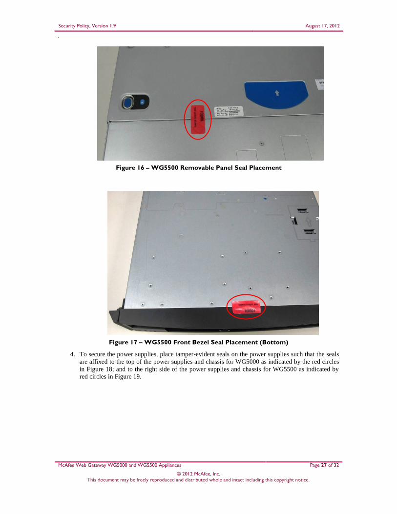
The WG5000 and WG5500 require 5 tamper-evident seals each. Two seals will be placed on the top of the
chassis, one across the front bezel and one across the removable top panel. One seal will be placed on the
bottom of the chassis, across the front bezel. The two power supplies located at the rear of the chassis will
require one tamper-evident seal each. The seals must be placed on the appliance as indicated by red circles
in the figures below. Follow these instructions to securely place the seals to the WG5000 and WG5500
modules:
1. To secure the front bezel, place a tamper-evident seal on the top such that it overlaps the front
bezel and metal cover at the top of the chassis. (Figure 12 and Figure 15)
2. In order to secure the removable panel on the top of the appliance, apply a tamper-evident seal
across the ridge. (Figure 13 and Figure 16)
3. Continue to secure the front bezel by placing a tamper-evident seal on the bottom such that it
overlaps the bottom portion of the bezel and the metal cover at the bottom of the chassis. (Figure
14 and Figure 17)

Security Policy, Version 1.9 August 17, 2012
McAfee Web Gateway WG5000 and WG5500 Appliances Page 25 of 32
© 2012 McAfee, Inc. This document may be freely reproduced and distributed whole and intact including this copyright notice.
Figure 12 – WG5000 Front Bezel Seal Placement (Top)
Figure 13 – WG5000 Removable Panel Seal Placement

Security Policy, Version 1.9 August 17, 2012
McAfee Web Gateway WG5000 and WG5500 Appliances Page 26 of 32
© 2012 McAfee, Inc. This document may be freely reproduced and distributed whole and intact including this copyright notice.
Figure 14 – WG5000 Front Bezel Seal Placement (Bottom)
Figure 15 – WG5500 Front Bezel Seal Placement (Top)
Security Policy, Version 1.9 August 17, 2012
McAfee Web Gateway WG5000 and WG5500 Appliances Page 27 of 32
© 2012 McAfee, Inc. This document may be freely reproduced and distributed whole and intact including this copyright notice.
Figure 16 – WG5500 Removable Panel Seal Placement
Figure 17 – WG5500 Front Bezel Seal Placement (Bottom)
4. To secure the power supplies, place tamper-evident seals on the power supplies such that the seals
are affixed to the top of the power supplies and chassis for WG5000 as indicated by the red circles
in Figure 18; and to the right side of the power supplies and chassis for WG5500 as indicated by
red circles in Figure 19.

Security Policy, Version 1.9 August 17, 2012
McAfee Web Gateway WG5000 and WG5500 Appliances Page 28 of 32
© 2012 McAfee, Inc. This document may be freely reproduced and distributed whole and intact including this copyright notice.
Figure 18 – WG5000 Power Supply Seals Placement
Figure 19 – WG5500 Power Supply Seals Placement
In the event that additional tempter-evident seals are needed, the CO can order tamper-evident seals by
contacting McAfee Technical Support and request a tamper-evident seal kit (Part No.: FRU-686-0089-00).
3.1.4 Power Supply Replacement
The module offers a service to the CO for power supply replacement. Only the CO is allowed to break the
tamper-evident seal in order to replace a power supply. After the power supply has been successfully
replaced, the CO is required to apply the tamper-evident label along the power supply module following the
instructions provided in Section 3.1.2.
3.2 Crypto-Officer Guidance The Crypto-Officer is responsible for initializing, performing security-relevant configuration, and
monitoring the module. The Crypto-Officer should set a BIOS password to prevent unauthorized
individuals from changing the module’s settings. During initial set up, the CO should change the default
admin password, UI server certificate, and the cluster CA. Additionally, the CO should ensure that the log

Security Policy, Version 1.9 August 17, 2012
McAfee Web Gateway WG5000 and WG5500 Appliances Page 29 of 32
© 2012 McAfee, Inc. This document may be freely reproduced and distributed whole and intact including this copyright notice.
file encryption and/or anonymization feature is turned off when the module is being operated in FIPS
mode. The CO should ensure proper application of tamper-evident labels after a power supply is replaced.
The Crypto-Officer can initiate the execution of self-tests, and can access the module’s status reporting
capability. Self-tests can be initiated at any time by power cycling the module.
3.2.1 Management
The Crypto-Officer is responsible for maintaining and monitoring the status of the module to ensure that
it’s running in its FIPS-Approved mode. Please refer to Section 3.1 above for guidance that the Crypto-
Officer must follow for the modules to be considered in a FIPS-Approved mode of operation.
For details regarding the management of the modules, please refer to the McAfee Web Gateway
Installation Guide.
3.2.2 Zeroization
Session keys are zeroized at the termination of the session, and are also cleared when the module is power-
cycled. This process includes the ANSI X9.31PRNG seed and ANSI X9.31 key. All other CSPs may be
zeroized when leaving the FIPS mode by reimaging the appliance. The Crypto-Officer must wait until the
module has successfully rebooted in order to verify that zeroization has completed.
3.3 User Guidance The User does not have the ability to configure sensitive information on the module.

Security Policy, Version 1.9 August 17, 2012
McAfee Web Gateway WG5000 and WG5500 Appliances Page 30 of 32
© 2012 McAfee, Inc. This document may be freely reproduced and distributed whole and intact including this copyright notice.
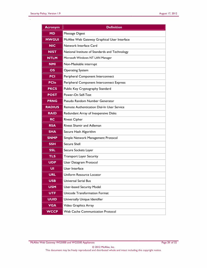
4 Acronyms This section describes the acronyms used throughout the document.
Table 11 – Acronyms
Acronym Definition
AC Alternating Current
AES Advanced Encryption Standard
ANSI American National Standards Institute
CBC Cipher-Block Chaining
CLI Command Line Interface
CMVP Cryptographic Module Validation Program
CO Crypto-Officer
CRNGT Continuous Random Number Generator Test
CSEC Communications Security Establishment Canada
CSP Critical Security Parameter
DB-9 D-subminiature 9-pin connector
DES Digital Encryption Standard
DNS Domain Name System
DSA Digital Signature Algorithm
ECB Electronic Codebook
EDC Error Detection Code
EMC Electromagnetic Compatibility
EMI Electromagnetic Interference
FIPS Federal Information Processing Standard
FTP File Transfer Protocol
GUI Graphical User Interface
HMAC (Keyed-) Hash Message Authentication Code
HTML Hypertext Markup Language
HTTP Hypertext Transfer Protocol
HTTPS Secure Hypertext Transfer Protocol
ID Identification
IP Internet Protocol
KAT Known Answer Test
LDAP Lightweight Directory Access Protocol
LED Light Emitting Diode
Security Policy, Version 1.9 August 17, 2012
McAfee Web Gateway WG5000 and WG5500 Appliances Page 31 of 32
© 2012 McAfee, Inc. This document may be freely reproduced and distributed whole and intact including this copyright notice.
Acronym Definition
MD Message Digest
MWGUI McAfee Web Gateway Graphical User Interface
NIC Network Interface Card
NIST National Institute of Standards and Technology
NTLM Microsoft Windows NT LAN Manager
NMI Non-Maskable interrupt
OS Operating System
PCI Peripheral Component Interconnect
PCIe Peripheral Component Interconnect Express
PKCS Public Key Cryptography Standard
POST Power-On Self-Test
PRNG Pseudo Random Number Generator
RADIUS Remote Authentication Dial-In User Service
RAID Redundant Array of Inexpensive Disks
RC Rivest Cipher
RSA Rivest Shamir and Adleman
SHA Secure Hash Algorithm
SNMP Simple Network Management Protocol
SSH Secure Shell
SSL Secure Sockets Layer
TLS Transport Layer Security
UDP User Datagram Protocol
UI User Interface
URL Uniform Resource Locator
USB Universal Serial Bus
USM User-based Security Model
UTF Unicode Transformation Format
UUID Universally Unique Identifier
VGA Video Graphics Array
WCCP Web Cache Communication Protocol

Prepared by: Corsec Security, Inc.
13135 Lee Jackson Memorial Highway, Suite 220 Fairfax, VA 22033
USA
Phone: +1 (703) 267-6050 Email: [email protected] http://www.corsec.com