McAfee, Inc. McAfee Firewall Enterprise 1100F
35
McAfee, Inc. McAfee Firewall Enterprise 1100F Hardware Part Number: NSA-1100-FWEX-F; Firmware Versions: 7.0.1.03 and 8.2.0 FIPS 140-2 Non-Proprietary Security Policy FIPS Security Level: 2 Document Version: 0.11 Prepared for: Prepared by: McAfee, Inc. Corsec Security, Inc. 3965 Freedom Circle Santa Clara, California 95054 United States of America 13135 Lee Jackson Memorial Highway, Suite 220 Fairfax, Virginia 22033 United States of America Phone: +1 (888) 847-8766 Phone: +1 (703) 267-6050 http://www.mcafee.com http://www.corsec.com
Transcript of McAfee, Inc. McAfee Firewall Enterprise 1100F

McAfee, Inc.
McAfee Firewall Enterprise 1100F Hardware Part Number: NSA-1100-FWEX-F; Firmware Versions: 7.0.1.03 and 8.2.0
FIPS 140-2 Non-Proprietary Security Policy
FIPS Security Level: 2
Document Version: 0.11
Prepared for: Prepared by:
McAfee, Inc. Corsec Security, Inc. 3965 Freedom Circle
Santa Clara, California 95054 United States of America
13135 Lee Jackson Memorial Highway, Suite 220 Fairfax, Virginia 22033 United States of America
Phone: +1 (888) 847-8766 Phone: +1 (703) 267-6050 http://www.mcafee.com http://www.corsec.com

Security Policy, Version 0.11 October 10, 2012
McAfee Firewall Enterprise 1100F Page 2 of 35
© 2012 McAfee, Inc. This document may be freely reproduced and distributed whole and intact including this copyright notice.
Table of Contents
1 INTRODUCTION ................................................................................................................... 4 1.1 PURPOSE ................................................................................................................................................................ 4 1.2 REFERENCES .......................................................................................................................................................... 4 1.3 DOCUMENT ORGANIZATION ............................................................................................................................ 4
2 MCAFEE FIREWALL ENTERPRISE 1100F ........................................................................... 5 2.1 OVERVIEW ............................................................................................................................................................. 5 2.2 MODULE SPECIFICATION ..................................................................................................................................... 7 2.3 MODULE INTERFACES .......................................................................................................................................... 7 2.4 ROLES AND SERVICES ........................................................................................................................................... 9
2.4.1 Crypto-Officer Role................................................................................................................................................. 9 2.4.2 User Role ................................................................................................................................................................ 12 2.4.3 Network User Role ............................................................................................................................................. 12 2.4.4 Authentication Mechanism ............................................................................................................................... 12
2.5 PHYSICAL SECURITY ........................................................................................................................................... 14 2.6 OPERATIONAL ENVIRONMENT ......................................................................................................................... 15 2.7 CRYPTOGRAPHIC KEY MANAGEMENT ............................................................................................................ 15 2.8 SELF-TESTS .......................................................................................................................................................... 22
2.8.1 Power-Up Self-Tests ............................................................................................................................................ 22 2.8.2 Conditional Self-Tests ......................................................................................................................................... 22 2.8.3 Critical Functions Self-Test ................................................................................................................................ 22
2.9 MITIGATION OF OTHER ATTACKS .................................................................................................................. 22
3 SECURE OPERATION ......................................................................................................... 23 3.1 CRYPTO-OFFICER GUIDANCE .......................................................................................................................... 23
3.1.1 Initialization ........................................................................................................................................................... 24 3.1.2 Management ........................................................................................................................................................ 31 3.1.3 Zeroization ............................................................................................................................................................ 31 3.1.4 Disabling FIPS Mode of Operation ................................................................................................................ 31
3.2 USER GUIDANCE ................................................................................................................................................ 31
4 ACRONYMS .......................................................................................................................... 32
Table of Figures FIGURE 1 – TYPICAL DEPLOYMENT SCENARIO ..................................................................................................................... 5 FIGURE 2 – MCAFEE FIREWALL ENTERPRISE 1100F .............................................................................................................. 6 FIGURE 3 – FRONT PANEL FEATURES AND INDICATORS ..................................................................................................... 8 FIGURE 4 – HARD DRIVE INDICATORS ................................................................................................................................... 8 FIGURE 5 – BACK PANEL FEATURES AND INDICATORS ........................................................................................................ 9 FIGURE 6 – VELCRO STRIP PLACEMENT ON TOP COVER ................................................................................................. 25 FIGURE 7 – VELCRO STRIP PLACEMENT IN REAR OF CHASSIS .......................................................................................... 25 FIGURE 8 – TAMPER-EVIDENT SEAL APPLICATION POSITIONS ......................................................................................... 26 FIGURE 9 – TAMPER-EVIDENT SEAL APPLICATION POSITIONS (POWER SUPPLIES) ....................................................... 27 FIGURE 10 – SERVICE STATUS ............................................................................................................................................... 29 FIGURE 11 – CONFIGURING FOR FIPS ................................................................................................................................ 30
List of Tables TABLE 1 – SECURITY LEVEL PER FIPS 140-2 SECTION ......................................................................................................... 6 TABLE 2 – MCAFEE FIREWALL ENTERPRISE 1100F PORTS AND INTERFACES .................................................................... 7 TABLE 3 – FIPS 140-2 LOGICAL INTERFACE MAPPINGS ...................................................................................................... 9 TABLE 4 – CRYPTO-OFFICER SERVICES ............................................................................................................................... 10

Security Policy, Version 0.11 October 10, 2012
McAfee Firewall Enterprise 1100F Page 3 of 35
© 2012 McAfee, Inc. This document may be freely reproduced and distributed whole and intact including this copyright notice.
TABLE 5 – USER SERVICES ..................................................................................................................................................... 12 TABLE 6 – NETWORK USER SERVICES ................................................................................................................................. 12 TABLE 7 – AUTHENTICATION MECHANISMS EMPLOYED BY THE MODULE .................................................................... 13 TABLE 8 – APPROVED CRYPTOGRAPHIC FUNCTIONS ...................................................................................................... 15 TABLE 9 – NON-APPROVED CRYPTOGRAPHIC FUNCTIONS USED IN FIPS MODE ....................................................... 16 TABLE 10 – SECURITY SERVICES IN NON-APPROVED MODE ........................................................................................... 17 TABLE 11 – CRYPTOGRAPHIC KEYS, CRYPTOGRAPHIC KEY COMPONENTS, AND CSPS ............................................ 18 TABLE 12 – SUMMARY OF FIREWALL ENTERPRISE DOCUMENTATION ............................................................................ 23 TABLE 13 – REQUIRED KEYS AND CSPS FOR SECURE OPERATION ................................................................................ 30 TABLE 14 – ACRONYMS ........................................................................................................................................................ 32

Security Policy, Version 0.11 October 10, 2012
McAfee Firewall Enterprise 1100F Page 4 of 35
© 2012 McAfee, Inc. This document may be freely reproduced and distributed whole and intact including this copyright notice.
1 Introduction
1.1 Purpose This is a non-proprietary Cryptographic Module Security Policy for the McAfee Firewall Enterprise 1100F
from McAfee, Inc. This Security Policy describes how the McAfee Firewall Enterprise 1100F meets the
security requirements of Federal Information Processing Standards (FIPS) Publication 140-2, which details
the U.S. and Canadian Government requirements for cryptographic modules. More information about the
FIPS 140-2 standard and validation program is available on the National Institute of Standards and
Technology (NIST) and the Communications Security Establishment Canada (CSEC) Cryptographic
Module Validation Program (CMVP) website at http://csrc.nist.gov/groups/STM/cmvp.
This document also describes how to run the module in a secure FIPS-Approved mode of operation. This
policy was prepared as part of the Level 2 FIPS 140-2 validation of the module. The McAfee Firewall
Enterprise 1100F is referred to in this document as the 1100F, the crypto-module, or the module.
1.2 References This document deals only with operations and capabilities of the module in the technical terms of a FIPS
140-2 cryptographic module security policy. More information is available on the module from the
following sources:
The McAfee corporate website (http://www.mcafee.com) contains information on the full line of
products from McAfee.
The CMVP website (http://csrc.nist.gov/groups/STM/cmvp/documents/140-1/140val-all.htm)
contains contact information for individuals to answer technical or sales-related questions for the
module.
1.3 Document Organization The Security Policy document is one document in a FIPS 140-2 Submission Package. In addition to this
document, the Submission Package contains:
Vendor Evidence document
Finite State Model document
Validation Submission Summary document
Other supporting documentation as additional references
This Security Policy and the other validation submission documentation were produced by Corsec Security,
Inc. under contract to McAfee. With the exception of this Non-Proprietary Security Policy, the FIPS 140-2
Submission Package is proprietary to McAfee and is releasable only under appropriate non-disclosure
agreements. For access to these documents, please contact McAfee.

Security Policy, Version 0.11 October 10, 2012
McAfee Firewall Enterprise 1100F Page 5 of 35
© 2012 McAfee, Inc. This document may be freely reproduced and distributed whole and intact including this copyright notice.
2 McAfee Firewall Enterprise 1100F
2.1 Overview
McAfee, Inc. is a global leader in Enterprise Security solutions. The company’s comprehensive portfolio
of network security products and solutions provides unmatched protection for the enterprise in the most
mission-critical and sensitive environments. The McAfee Firewall Enterprise 1100F appliance is created to
meet the specific needs of organizations of all types and enable those organizations to reduce costs and
mitigate the evolving risks that threaten today's networks and applications.
Consolidating all major perimeter security functions into one system, McAfee's Firewall Enterprise
appliances are the strongest self-defending perimeter firewalls in the world. Built with a comprehensive
combination of high-speed application proxies, McAfee's TrustedSource™ reputation-based global
intelligence, and signature-based security services, Firewall Enterprise defends networks and Internet-
facing applications from all types of malicious threats, both known and unknown.
Figure 1 – Typical Deployment Scenario
Firewall Enterprise appliances are market-leading, next-generation firewalls that provide application
visibility and control even beyond Unified Threat Management (UTM) for multi-layer security – and the
highest network performance. Global visibility of dynamic threats is the centerpiece of Firewall Enterprise
and one of the key reasons for its superior ability to detect unknown threats along with the known. Firewall
Enterprise appliances deliver the best-of-breed in security systems to block attacks, including:
Viruses
Worms
Trojans
Intrusion attempts
Spam and phishing tactics
Cross-site scripting
Structured Query Language (SQL) injections
Denial of service (DoS)
Attacks hiding in encrypted protocols
A Firewall Enterprise appliance is managed using a proprietary graphical user interface (GUI), referred as
Admin Console, and a command line management interface. Hundreds of Firewall Enterprise appliances

Security Policy, Version 0.11 October 10, 2012
McAfee Firewall Enterprise 1100F Page 6 of 35
© 2012 McAfee, Inc. This document may be freely reproduced and distributed whole and intact including this copyright notice.
can be managed centrally using McAfee’s Control Center tool. Firewall Enterprise security features
include:
Firewall feature for full application filtering, web application filtering, and Network Address
Translation (NAT)
Authentication using local database, Active Directory, LDAP1, RADIUS
2, Windows Domain
Authentication, and more
High Availability (HA)
Geo-location filtering
Encrypted application filtering using TLS3 and IPsec
4 protocols
Intrusion Prevention System
Networking and Routing
Management via Simple Network Management Protocol (SNMP) version 3
Although SNMP v3 can support AES encryption, it does not utilize a FIPS-Approved key generation
method; therefore, the module has been designed to block the ability to view or alter critical security
parameters (CSPs) through this interface. Also note that the SNMP v3 interface is a management interface
for the McAfee Firewall Enterprise 1100F and that no CSPs or user data are transmitted over this interface.
The McAfee Firewall Enterprise 1100F is a 1U rack-mountable appliance appropriate for mid- to large-
sized organizations. A front view of the cryptographic module is shown in Figure 2 below.
Figure 2 – McAfee Firewall Enterprise 1100F
The McAfee Firewall Enterprise 1100F is validated at the FIPS 140-2 Section levels shown in Table 1.
Table 1 – Security Level Per FIPS 140-2 Section
Section Section Title Level
1 Cryptographic Module Specification 2
2 Cryptographic Module Ports and Interfaces 2
3 Roles, Services, and Authentication 2
4 Finite State Model 2
5 Physical Security 2
6 Operational Environment N/A
7 Cryptographic Key Management 2
8 EMI/EMC5 2
1 LDAP – Lightweight Directory Access Protocol 2 RADIUS – Remote Authentication Dial-In User Service 3 TLS – Transport Layer Security 4 IPsec – Internet Protocol Security
Security Policy, Version 0.11 October 10, 2012
McAfee Firewall Enterprise 1100F Page 7 of 35
© 2012 McAfee, Inc. This document may be freely reproduced and distributed whole and intact including this copyright notice.
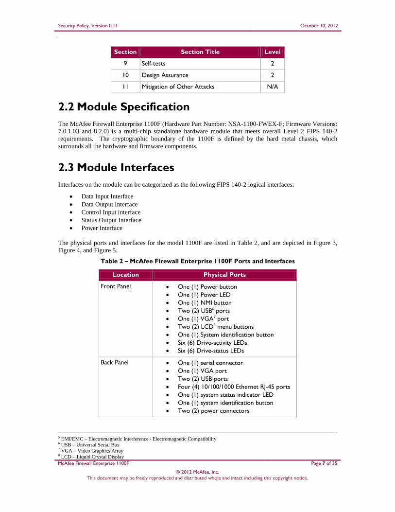
Section Section Title Level
9 Self-tests 2
10 Design Assurance 2
11 Mitigation of Other Attacks N/A
2.2 Module Specification
The McAfee Firewall Enterprise 1100F (Hardware Part Number: NSA-1100-FWEX-F; Firmware Versions:
7.0.1.03 and 8.2.0) is a multi-chip standalone hardware module that meets overall Level 2 FIPS 140-2
requirements. The cryptographic boundary of the 1100F is defined by the hard metal chassis, which
surrounds all the hardware and firmware components.
2.3 Module Interfaces
Interfaces on the module can be categorized as the following FIPS 140-2 logical interfaces:
Data Input Interface
Data Output Interface
Control Input interface
Status Output Interface
Power Interface
The physical ports and interfaces for the model 1100F are listed in Table 2, and are depicted in Figure 3,
Figure 4, and Figure 5.
Table 2 – McAfee Firewall Enterprise 1100F Ports and Interfaces
Location Physical Ports
Front Panel One (1) Power button
One (1) Power LED
One (1) NMI button
Two (2) USB6 ports
One (1) VGA7 port
Two (2) LCD8 menu buttons
One (1) System identification button
Six (6) Drive-activity LEDs
Six (6) Drive-status LEDs
Back Panel One (1) serial connector
One (1) VGA port
Two (2) USB ports
Four (4) 10/100/1000 Ethernet RJ-45 ports
One (1) system status indicator LED
One (1) system identification button
Two (2) power connectors
5 EMI/EMC – Electromagnetic Interference / Electromagnetic Compatibility 6 USB – Universal Serial Bus 7 VGA – Video Graphics Array 8 LCD – Liquid Crystal Display

Security Policy, Version 0.11 October 10, 2012
McAfee Firewall Enterprise 1100F Page 8 of 35
© 2012 McAfee, Inc. This document may be freely reproduced and distributed whole and intact including this copyright notice.
Note the following acronyms used in the figures below:
NMI – Nonmaskable Interrupt
PCIe – Peripheral Component Interconnect Express
iDRAC6 – Integrated Dell™ Remote Access Controller 6
1. Power-on indicator, power button
2. NMI button
3. USB connectors (2)
4. Video connector
5. LCD menu buttons
6. LCD panel
7. System identification button
8. Hard drives (8)
9. Optical drive (optional)
10. System identification panel
Figure 3 – Front Panel Features and Indicators
1. Drive-activity indicator (green)
2. Drive-status indicator (green/amber)
Figure 4 – Hard Drive Indicators
1. iDRAC6 Enterprise port (optional)
2. iDRAC6 Vflash media slot (optional)
3. Serial connector
4. PCIe slot 1
5. Video connector
6. USB connectors (2)
7. PCIe slot 2
8. 10/100/1000 Ethernet connectors (4)
9. System status indicator connector
10. System status indicator
11. System identification button
12. Power supply 1
13. Power supply 2

Security Policy, Version 0.11 October 10, 2012
McAfee Firewall Enterprise 1100F Page 9 of 35
© 2012 McAfee, Inc. This document may be freely reproduced and distributed whole and intact including this copyright notice.
Figure 5 – Back Panel Features and Indicators
All of these physical interfaces are separated into logical interfaces defined by FIPS 140-2, as described in
Table 3.
Table 3 – FIPS 140-2 Logical Interface Mappings
FIPS 140-2 Interface McAfee Firewall Enterprise 1100F Physical Port
Data Input Connectors (Ethernet)
Data Output Connectors (Ethernet)
Control Input Buttons (NMI, power, LCD menu, system identification) and
connectors (Ethernet, USB, serial)
Status Output Connectors (video, Ethernet, serial), and LED indicators
(power-on, drive activity, drive status, system status)
Power Connectors (power)
Note that a metal bezel is mounted to the chassis front (see Figure 2 above). A lock on the bezel is used to
prevent unauthorized access to system peripherals, hard drives, and the control panel. Of the available
front panel features and indicators (see Figure 3), only the LCD panel and hard drive LEDs are accessible
when the bezel is installed.
2.4 Roles and Services
The module supports role-based authentication. There are three authorized roles in the module that an
operator may assume: a Crypto-Officer (CO) role, a User role, and a Network User role.
Please note that the keys and Critical Security Parameters (CSPs) listed in the Services tables below
indicate the type of access required:
R (Read): The CSP is read
W (Write): The CSP is established, generated, modified, or zeroized
X (Execute): The CSP is used within an Approved or Allowed security function or authentication
mechanism
2.4.1 Crypto-Officer Role
The Crypto-Officer role performs administrative services on the module, such as initialization,
configuration, and monitoring of the module. Before accessing the module for any administrative service,
the operator must authenticate to the module. The module offers management interfaces in three ways:
Administration Console
Command Line Interface (CLI)
SNMP v3
The Administration Console (or Admin Console) is the graphical software that runs on a Windows
computer within a connected network. Admin Console is McAfee’s proprietary GUI management software
tool that needs to be installed on a Windows-based workstation. This is the primary management tool. All
Admin Console sessions to the module are protected over secure TLS channel. Authentication of the
administrator is through a username/password prompt checked against a local password database.

Security Policy, Version 0.11 October 10, 2012
McAfee Firewall Enterprise 1100F Page 10 of 35
© 2012 McAfee, Inc. This document may be freely reproduced and distributed whole and intact including this copyright notice.
CLI sessions are offered by the module for troubleshooting. The CLI is accessed locally over the serial
port or by a direct-connected keyboard and mouse, while remote access is via Secure Shell (SSH) session.
The CO authenticates to the module using a username and password.
The crypto-module uses the SNMP v3 protocol for remote management, and to provide information about
the state and statistics as part of a Network Management System (NMS).
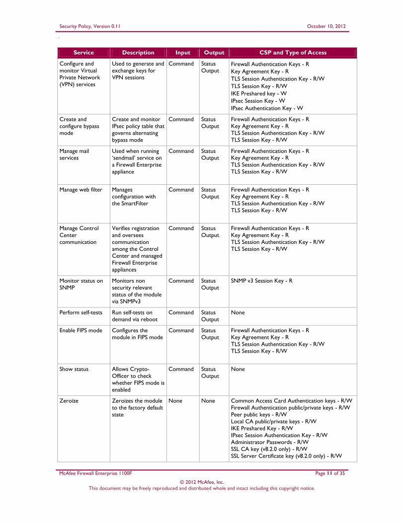
Services provided to the Crypto-Officer are provided in Table 4 below.
Table 4 – Crypto-Officer Services
Service Description Input Output CSP and Type of Access
Authenticate to the
Admin Console
Used when
administrators login
to the appliance using
the Firewall
Enterprise Admin
Console
Command Status
Output
Firewall Authentication Keys - R
Key Agreement Key - R
TLS Session Authentication Key - R/W
TLS Session Key - R/W
Administrative Password - R
Authenticate to the
Admin Console
using Common Access Card (CAC)
Used when
administrators login
to the appliance with CAC authentication
to access the Firewall
Enterprise Admin
Console
Command Status
Output
Common Access Card Authentication Keys - R
Key Agreement Key - R
TLS Session Authentication Key - R/W TLS Session Key - R/W
Common Access Card One-Time Password - R
Authenticate to the
Admin CLI
Used when
administrators login
to the appliance using
the Firewall
Enterprise Admin
CLI
Command Status
Output
Firewall Authentication Keys - R
Key Agreement Key - R
SSH Session Authentication Key - R/W
SSH Session Key - R/W
Administrative Password - R
Authenticate to the
Admin CLI using
Common Access
Card (CAC)
Used when
administrators login
to the appliance with
CAC authentication
to access the Firewall
Enterprise Admin
CLI
Command Status
Output
Common Access Card Authentication Keys - R
Key Agreement Key - R
SSH Session Authentication Key - R/W
SSH Session Key - R/W
Common Access Card One-Time Password - R
Authenticate to the
local console
Used when
administrators login
to the appliance via the local console
Command Status
Output Administrator Password - R
Change password Allows external users
to use a browser to
change their Firewall
Enterprise, SafeWord
PremierAccess, or
LDAP login password
Command Status
Output
Firewall Authentication Keys - R
Key Agreement Key - R
TLS Session Authentication Key - R/W
TLS Session Key - R/W
Administrative Password - R/W
Configure cluster
communication
Services required to
communicate with
each other in Firewall
Enterprise multi-
appliance
configurations
Command Status
Output
Firewall Authentication Keys - R
Key Agreement Key - R
TLS Session Authentication Key - R/W
TLS Session Key - R/W
Security Policy, Version 0.11 October 10, 2012
McAfee Firewall Enterprise 1100F Page 11 of 35
© 2012 McAfee, Inc. This document may be freely reproduced and distributed whole and intact including this copyright notice.
Service Description Input Output CSP and Type of Access
Configure and
monitor Virtual
Private Network
(VPN) services
Used to generate and
exchange keys for
VPN sessions
Command Status
Output Firewall Authentication Keys - R
Key Agreement Key - R
TLS Session Authentication Key - R/W
TLS Session Key - R/W
IKE Preshared key - W
IPsec Session Key - W
IPsec Authentication Key - W
Create and
configure bypass
mode
Create and monitor
IPsec policy table that
governs alternating
bypass mode
Command Status
Output
Firewall Authentication Keys - R
Key Agreement Key - R
TLS Session Authentication Key - R/W
TLS Session Key - R/W
Manage mail services
Used when running ‘sendmail’ service on
a Firewall Enterprise
appliance
Command Status Output
Firewall Authentication Keys - R Key Agreement Key - R
TLS Session Authentication Key - R/W
TLS Session Key - R/W
Manage web filter Manages
configuration with
the SmartFilter
Command Status
Output
Firewall Authentication Keys - R
Key Agreement Key - R
TLS Session Authentication Key - R/W
TLS Session Key - R/W
Manage Control
Center
communication
Verifies registration
and oversees
communication
among the Control
Center and managed
Firewall Enterprise
appliances
Command Status
Output
Firewall Authentication Keys - R
Key Agreement Key - R
TLS Session Authentication Key - R/W
TLS Session Key - R/W
Monitor status on
SNMP
Monitors non
security relevant
status of the module
via SNMPv3
Command Status
Output
SNMP v3 Session Key - R
Perform self-tests Run self-tests on
demand via reboot
Command Status
Output
None
Enable FIPS mode Configures the
module in FIPS mode
Command Status
Output
Firewall Authentication Keys - R
Key Agreement Key - R
TLS Session Authentication Key - R/W
TLS Session Key - R/W
Show status Allows Crypto-
Officer to check
whether FIPS mode is
enabled
Command Status
Output
None
Zeroize Zeroizes the module
to the factory default
state
None None Common Access Card Authentication keys - R/W
Firewall Authentication public/private keys - R/W
Peer public keys - R/W
Local CA public/private keys - R/W
IKE Preshared Key - R/W
IPsec Session Authentication Key - R/W
Administrator Passwords - R/W
SSL CA key (v8.2.0 only) - R/W
SSL Server Certificate key (v8.2.0 only) - R/W

Security Policy, Version 0.11 October 10, 2012
McAfee Firewall Enterprise 1100F Page 12 of 35
© 2012 McAfee, Inc. This document may be freely reproduced and distributed whole and intact including this copyright notice.
2.4.2 User Role
Users employ the services of the modules for establishing VPN9 or TLS connections via Ethernet port.
Access to these services requires the operator to first authenticate to the module. Descriptions of the
services available to the Users are provided in Table 5 below.
Table 5 – User Services
Service Description Input Output CSP and Type of Access
Establish an
authenticated TLS
connection
Establish a TLS
connection (requires
operator
authentication)
Command Secure TLS
session
established
Firewall Authentication Keys - R
Key Agreement Key - R
TLS Session Authentication Key - R/W
TLS Session Key - R/W
SSL CA key (v8.2.0 only) - R
SSL Server Certificate key (v8.2.0 only) - R
Establish a VPN
connection
Establish a VPN
connection over
IPsec tunnel
Command Secure VPN
tunnel
established
Firewall Authentication Keys - R
Key Agreement Key - R
IKE Session Authentication Key - W
IKE Session Key – W
IKE Preshared Key - R
IPsec Session Key – R/W
IPsec Authentication Key – R/W
2.4.3 Network User Role
The Network User role is defined as users within the secured network who have been given access to the
device by a security policy rule granted by the Crypto-Officer. Network users communicate via plaintext
connections (bypass). The Network User role does not require authentication.
Table 6 lists all the services that are available to the Network User role.
Table 6 – Network User Services
Service Description Input Output CSP and Type of Access
Establish a plaintext
connection
Establish a plaintext
connection
Command Traffic in
plaintext
None
2.4.4 Authentication Mechanism
The module employs the authentication methods described in Table 7 to authenticate Crypto-Officers and
Users.
9 VPN – Virtual Private Network

Security Policy, Version 0.11 October 10, 2012
McAfee Firewall Enterprise 1100F Page 13 of 35
© 2012 McAfee, Inc. This document may be freely reproduced and distributed whole and intact including this copyright notice.
Table 7 – Authentication Mechanisms Employed by the Module
Role Type of Authentication Authentication Strength
Crypto-Officer Password Passwords are required to be at least 8 characters long. The
password requirement is enforced by the Security Policy. The
maximum password length is 64 characters. Case-sensitive
alphanumeric characters and special characters can be used
with repetition, which gives a total of 94 characters to choose
from. The chance of a random attempt falsely succeeding is
1:948, or 1: 6,095,689,385,410,816.
This would require about 60,956,893,854 attempts in one
minute to raise the random attempt success rate to more than
1:100,000. The fastest connection supported by the module is
1 Gbps. Hence, at most 60,000,000,000 bits of data (1000 ×
106 × 60 seconds, or 6 x 10¹⁰) can be transmitted in one minute. At that rate and assuming no overhead, a maximum of
812,759 attempts can be transmitted over the connection in
one minute. The maximum number of attempts that this
connection can support is less than the amount required per
minute to achieve a 1:100,000 chance of a random attempt
falsely succeeding.
Common Access Card One-time passwords are required to be at least 8 characters long. The password requirement is enforced by the Security
Policy. The maximum password length is 128 characters. The
password consists of a modified base-64 alphabet, which gives
a total of 64 characters to choose from. With the possibility of
using repeating characters, the chance of a random attempt
falsely succeeding is 1:648, or 1:281,474,976,710,656.
This would require about 2,814,749,767 attempts in one
minute to raise the random attempt success rate to more than
1:100,000. The fastest connection supported by the module is
1 Gbps. Hence, at most 60,000,000,000 bits of data (1000 ×
106 × 60 seconds, or 6 x 10¹⁰) can be transmitted in one
minute. At that rate, and assuming no overhead, a maximum
of only 937,500,000 8-character passwords can be transmitted over the connection in one minute. The maximum number of
attempts that this connection can support is less than the
amount required per minute to achieve a 1:100,000 chance of
a random attempt falsely succeeding.

Security Policy, Version 0.11 October 10, 2012
McAfee Firewall Enterprise 1100F Page 14 of 35
© 2012 McAfee, Inc. This document may be freely reproduced and distributed whole and intact including this copyright notice.
Role Type of Authentication Authentication Strength
User Password, or Certificate, IP
Address
Passwords are required to be at least 8 characters long. The
password requirement is enforced by the Security Policy. The
maximum password length is 64 characters. Case-sensitive
alphanumeric characters and special characters can be used
with repetition, which gives a total of 94 characters to choose from. The chance of a random attempt falsely succeeding is
1:948, or 1: 6,095,689,385,410,816.
This would require about 60,956,893,854 attempts in one
minute to raise the random attempt success rate to more than
1:100,000. The fastest connection supported by the module is
1 Gbps. Hence, at most 60,000,000,000 bits of data (1000 ×
106 × 60 seconds, or 6 x 10¹⁰) can be transmitted in one
minute. At that rate and assuming no overhead, a maximum of
812,759 attempts can be transmitted over the connection in
one minute. The maximum number of attempts that this
connection can support is less than the amount required per
minute to achieve a 1:100,000 chance of a random attempt falsely succeeding.
Certificates used as part of TLS, SSH, and IKE10/IPsec are at a
minimum 1024 bits. The chance of a random attempt falsely
succeeding is 1:280, or 1:120,893 x 1024.
The fastest network connection supported by the module is
1000 Mbps. Hence, at most 60,000,000,000 bits of data (1000
× 106 × 60 seconds, or 6 × 10¹⁰) can be transmitted in one
minute. The passwords are sent to the module via security
protocols IPsec, TLS, and SSH. These protocols provide
strong encryption (AES 128-bit key at minimum, providing 128
bits of security) and require large computational and
transmission capability. The probability that a random attempt will succeed or a false acceptance will occur is less than 1:2128
x 844.
2.5 Physical Security
The McAfee Firewall Enterprise 1100F is a multi-chip standalone cryptographic module. The module is
contained in a hard metal chassis which is defined as the cryptographic boundary of the module. The
module’s chassis is opaque within the visible spectrum. The enclosure of the module has been designed to
satisfy Level 2 physical security requirements. There are a limited set of ventilation holes provided in the
case that, when coupled with the installation of opacity baffles, obscure the internal components of the
module. Tamper-evident seals are applied to the case to provide physical evidence of attempts to remove
the chassis cover or front bezel. Additionally, the tamper-evident seals must be inspected periodically for
tamper evidence. The placement of the opacity baffles and tamper-evident seals can be found in Secure
Operation section of this document.
The 1100F system has been tested and found conformant to the EMI/EMC requirements specified by 47
Code of Federal Regulations, Part 15, Subpart B, Unintentional Radiators, Digital Devices, Class A (i.e.,
for business use).
10 IKE – Internet Key Exchange
Security Policy, Version 0.11 October 10, 2012
McAfee Firewall Enterprise 1100F Page 15 of 35
© 2012 McAfee, Inc. This document may be freely reproduced and distributed whole and intact including this copyright notice.
2.6 Operational Environment
The operational environment requirements do not apply to the McAfee Firewall Enterprise 1100F, because
the module does not provide a general-purpose operating system (OS) to the user. The OS has limited
operational environment and only the module’s custom written image can be run on the system. The
module provides a method to update the firmware in the module with a new version. This method involves
downloading a digitally signed firmware update to the module.
2.7 Cryptographic Key Management
The module implements three firmware cryptographic libraries to offer secure networking protocols and
cryptographic functionalities. The firmware libraries for MFE v7.0.1.03 are:
Cryptographic Library for SecureOS® (CLSOS) Version 7.0.1.01 for 32-bit systems
CLSOS Version 7.0.1.01 for 64-bit systems
Kernel CLSOS (KCLSOS) Version 7.0.1.01
The firmware libraries for MFE v8.2 are:
CLSOS Version 7.0.1.01 for 32-bit systems
CLSOS Version 7.0.1.01 for 64-bit systems
KCLSOS Version 8.2
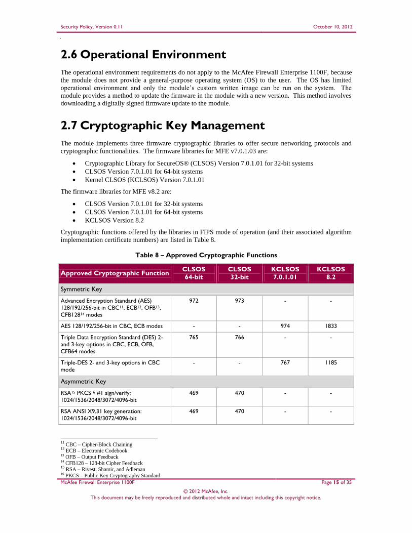
Cryptographic functions offered by the libraries in FIPS mode of operation (and their associated algorithm
implementation certificate numbers) are listed in Table 8.
Table 8 – Approved Cryptographic Functions
Approved Cryptographic Function CLSOS
64-bit
CLSOS
32-bit
KCLSOS
7.0.1.01
KCLSOS
8.2
Symmetric Key
Advanced Encryption Standard (AES)
128/192/256-bit in CBC11, ECB12, OFB13,
CFB12814 modes
972 973 - -
AES 128/192/256-bit in CBC, ECB modes - - 974 1833
Triple Data Encryption Standard (DES) 2-
and 3-key options in CBC, ECB, OFB,
CFB64 modes
765 766 - -
Triple-DES 2- and 3-key options in CBC
mode
- - 767 1185
Asymmetric Key
RSA15 PKCS16 #1 sign/verify:
1024/1536/2048/3072/4096-bit
469 470 - -
RSA ANSI X9.31 key generation:
1024/1536/2048/3072/4096-bit
469 470 - -
11
CBC – Cipher-Block Chaining 12
ECB – Electronic Codebook 13 OFB – Output Feedback 14 CFB128 – 128-bit Cipher Feedback 15
RSA – Rivest, Shamir, and Adleman 16 PKCS – Public Key Cryptography Standard

Security Policy, Version 0.11 October 10, 2012
McAfee Firewall Enterprise 1100F Page 16 of 35
© 2012 McAfee, Inc. This document may be freely reproduced and distributed whole and intact including this copyright notice.
Approved Cryptographic Function CLSOS
64-bit
CLSOS
32-bit
KCLSOS
7.0.1.01
KCLSOS
8.2
Digital Signature Algorithm (DSA) signature
verification: 1024-bit
338 339 - -
Secure Hash Standard
SHA17-1, SHA-256, SHA-384, and SHA-512 941 942 943 1612
Message Authentication
HMAC18 using SHA-1, SHA-256, SHA-384,
and SHA-512
544 545 546 1086
Random Number Generators (RNG)
ANSI19 X9.31 Appendix A.2.4 PRNG 549 550 551 964
NOTE: As of December 31, 2010, the following algorithms listed in the table above are considered “deprecated”. For details
regarding algorithm deprecation, please refer to NIST Special Publication 800-131A.
Encryption using 2-key Triple DES
Random number generation using ANSI X9.31-1998
Digital signature generation using SHA-1
Digital signature verification using 1024-bit DSA
Digital signature generation/verification using 1024-bit RSA
HMAC generation and verification using key lengths less than 112 bits
Non-FIPS-Approved cryptographic functions offered by the libraries in FIPS mode of operation are listed
in Table 9.
Table 9 – Non-Approved Cryptographic Functions Used in FIPS Mode
Cryptographic Function CLSOS
64-bit
CLSOS
32-bit
KCLSOS
7.0.1.01
KCLSOS
8.2
Diffie-Hellman (DH): 1024/2048 bits20 (key
agreement)
implemented implemented - -
RSA encrypt/decrypt21 (key transport):
1024/1536/2048/3072/4096-bit
implemented implemented - -
NOTE: As of December 31, 2010, the following algorithms listed in the table above are considered “deprecated”. For details
regarding algorithm deprecation, please refer to NIST Special Publication 800-131A.
1024-bit Diffie-Hellman key agreement
1024-bit RSA key transport
While in non-Approved mode, the module offers or uses both non-compliant and non-Approved
cryptographic functions. These algorithms are implemented in the CLSOS firmware. Table 10 lists the
security services offered by the module while in non-Approved mode, and the cryptographic functions that
provide those services.
17 SHA – Secure Hash Algorithm 18 HMAC – (Keyed-) Hash Message Authentication Code 19 ANSI – American National Standards Institute 20 Caveat: Diffie-Hellman (key agreement; key establishment methodology provides 80 or 112 bits of encryption strength) 21 Caveat: RSA (key wrapping; key establishment methodology provides between 80 and 150 bits of encryption strength)

Security Policy, Version 0.11 October 10, 2012
McAfee Firewall Enterprise 1100F Page 17 of 35
© 2012 McAfee, Inc. This document may be freely reproduced and distributed whole and intact including this copyright notice.
Table 10 – Security Services in Non-Approved Mode
Security Service Cryptographic Function
Non-Compliant Non-Approved
Symmetric encryption/decryption AES
Triple-DES
CAST22-128
DES
RC2
RC4
Digital signing DSA
RSA
-
Hashing SHA MD2
MD5
Message authentication HMAC -
Random number generation ANSI X9.31 RNG -
Key agreement Diffie-Hellman
Elliptic Curve Diffie-
Hellman
-
22 CAST – Carlisle Adams and Stafford Tavares
Security Policy, Version 0.11 October 10, 2012
McAfee Firewall Enterprise 1100F Page 18 of 35
© 2012 McAfee, Inc. This document may be freely reproduced and distributed whole and intact including this copyright notice.
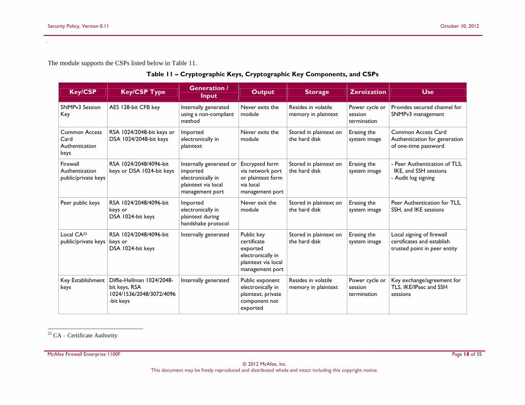
The module supports the CSPs listed below in Table 11.
Table 11 – Cryptographic Keys, Cryptographic Key Components, and CSPs
Key/CSP Key/CSP Type Generation /
Input Output Storage Zeroization Use
SNMPv3 Session
Key
AES 128-bit CFB key Internally generated
using a non-compliant
method
Never exits the
module
Resides in volatile
memory in plaintext
Power cycle or
session
termination
Provides secured channel for
SNMPv3 management
Common Access
Card
Authentication
keys
RSA 1024/2048-bit keys or
DSA 1024/2048-bit keys
Imported
electronically in
plaintext
Never exits the
module
Stored in plaintext on
the hard disk
Erasing the
system image
Common Access Card
Authentication for generation
of one-time password
Firewall
Authentication
public/private keys
RSA 1024/2048/4096-bit
keys or DSA 1024-bit keys
Internally generated or
imported
electronically in
plaintext via local
management port
Encrypted form
via network port
or plaintext form
via local
management port
Stored in plaintext on
the hard disk
Erasing the
system image
- Peer Authentication of TLS,
IKE, and SSH sessions
- Audit log signing
Peer public keys RSA 1024/2048/4096-bit
keys or
DSA 1024-bit keys
Imported
electronically in
plaintext during
handshake protocol
Never exit the
module
Stored in plaintext on
the hard disk
Erasing the
system image
Peer Authentication for TLS,
SSH, and IKE sessions
Local CA23
public/private keys
RSA 1024/2048/4096-bit
keys or
DSA 1024-bit keys
Internally generated Public key
certificate
exported
electronically in
plaintext via local
management port
Stored in plaintext on
the hard disk
Erasing the
system image
Local signing of firewall
certificates and establish
trusted point in peer entity
Key Establishment keys
Diffie-Hellman 1024/2048-bit keys, RSA
1024/1536/2048/3072/4096
-bit keys
Internally generated Public exponent electronically in
plaintext, private
component not
exported
Resides in volatile memory in plaintext
Power cycle or session
termination
Key exchange/agreement for TLS, IKE/IPsec and SSH
sessions
23 CA – Certificate Authority

Security Policy, Version 0.11 October 10, 2012
McAfee Firewall Enterprise 1100F Page 19 of 35
© 2012 McAfee, Inc. This document may be freely reproduced and distributed whole and intact including this copyright notice.
Key/CSP Key/CSP Type Generation /
Input Output Storage Zeroization Use
TLS Session
Authentication
Key
HMAC SHA-1 key Internally generated Never exits the
module
Resides in volatile
memory in plaintext
Power cycle or
session
termination
Data authentication for TLS
sessions
TLS Session Key Triple-DES, AES-128, AES-
256
Internally generated Never exits the
module
Resides in volatile
memory in plaintext
Power cycle or
session termination
Data encryption/decryption
for TLS sessions
IKE Session
Authentication
Key
HMAC SHA-1 key Internally generated Never exists the
module
Resides in volatile
memory in plaintext
Power cycle or
session
termination
Data authentication for IKE
sessions
IKE Session Key Triple-DES, AES-128, AES-
256
Internally generated
Never exits the
module
Resides in volatile
memory in plaintext
Power cycle or
session
termination
Data encryption/decryption
for IKE sessions
IKE Preshared
Key
Triple-DES, AES-128, AES-
256
- Imported in
encrypted form
over network port
or local
management port in
plaintext
- Manually entered
Never exits the
module
Stored in plaintext on
the hard disk
Erasing the
system image
Data encryption/decryption
for IKE sessions
IPsec Session
Authentication
Key
HMAC SHA-1 key - Imported in
encrypted form
over network port
or local
management port in
plaintext
- Internally generated
- Manually entered
Never exits the
module
- Stored in plaintext
on the hard disk
- Resides in volatile
memory
Power cycle Data authentication for IPsec
sessions
IPsec Session Key Triple-DES, AES-128, AES-
256
Internally generated Never exits the
module
Resides in volatile
memory in plaintext
Power cycle Data encryption/decryption
for IPsec sessions

Security Policy, Version 0.11 October 10, 2012
McAfee Firewall Enterprise 1100F Page 20 of 35
© 2012 McAfee, Inc. This document may be freely reproduced and distributed whole and intact including this copyright notice.
Key/CSP Key/CSP Type Generation /
Input Output Storage Zeroization Use
IPsec Preshared
Session Key
Triple-DES, AES-128, AES-
256
- Imported in
encrypted form
over network port
or local
management port in
plaintext
- Manually entered
Exported
electronically in
plaintext
Stored in plaintext on
the hard disk
Power cycle Data encryption/decryption
for IPsec sessions
SSH Session
Authentication
Key
HMAC-SHA1 key Internally generated Never exists the
module
Resides in volatile
memory in plaintext
Power cycle or
session
termination
Data authentication for SSH
sessions
SSH Session Key Triple-DES, AES-128, AES-
256
Internally generated Never exists the
module
Resides in volatile
memory in plaintext
Power cycle or
session
termination
Data encryption/decryption
for SSH sessions
Package
Distribution
Public Key
DSA 1024-bit public key Externally generated
and hard coded in the
image
Never exits the
module
Hard coded in
plaintext
Erasing the
system image
Verifies the signature
associated with a firewall
update package
License
Management
Public Key
DSA 1024-bit public key Externally generated
and hard coded in the
image
Never exits the
module
Hard coded in
plaintext
Erasing the
system image
Verifies the signature
associated with a firewall
license
Administrator
Passwords
PIN Manually or
electronically
imported
Never exits the
module
Stored on the hard
disk through one-way
hash obscurement
Erasing the
system image
Standard Unix authentication
for administrator login
Common Access
Card one-time
password
8-character (minimum)
ASCII string
Internally generated;
Manually or
electronically imported
Exported
electronically in
encrypted form over TLS
Resides in volatile
memory inside the
CAC Warder process
Password
expiration,
session termination, or
power cycle
Common Access Card
authentication for
administrator login
32-bit CLSOS
X9.31 PRNG seed
16 bytes of seed value Internally generated by
KCLSOS ANSI X9.31
PRNG
Never exits the
module
Resides in volatile
memory in plaintext
Power cycle Generates FIPS-Approved
random number
32-bit CLSOS
ANSI X9.31
PRNG key
AES-256 Internally generated by
KCLSOS ANSI X9.31
PRNG
Never exits the
module
Resides in volatile
memory in plaintext
Power cycle Generates FIPS-Approved
random number

Security Policy, Version 0.11 October 10, 2012
McAfee Firewall Enterprise 1100F Page 21 of 35
© 2012 McAfee, Inc. This document may be freely reproduced and distributed whole and intact including this copyright notice.
Key/CSP Key/CSP Type Generation /
Input Output Storage Zeroization Use
64-bit CLSOS
ANSI X9.31
PRNG seed
16 bytes of seed value Internally generated by
KCLSOS ANSI X9.31
PRNG
Never exits the
module
Resides in volatile
memory in plaintext
Power cycle Generates FIPS-Approved
random number
64-bit CLSOS
ANSI X9.31 PRNG key
AES-256 Internally generated by
KCLSOS ANSI X9.31 PRNG
Never exits the
module
Resides in volatile
memory in plaintext
Power cycle Generates FIPS-Approved
random number
KCLSOS ANSI
X9.31 PRNG seed
16 bytes of seed value Internally generated
from entropy sources
Never exits the
module
Resides in volatile
memory in plaintext
Power cycle Generates FIPS-Approved
random number
KCLSOS ANSI
X9.31 PRNG key
AES-256 Internally generated
from entropy sources
Never exits the
module
Resides in volatile
memory in plaintext
Power cycle Generates FIPS-Approved
random number
SSL CA key
(v8.2.0 only)
RSA 1024/2048-bit key or
DSA 1024/2048-bit key
Internally generated Exported
electronically in
ciphertext via
network port or
in plaintext via
local management
port
Stored in plaintext on
the hard disk
Erasing the
system image
Signing temporary server
certificates for TLS re-
encryption
SSL Server
Certificate key
(v8.2.0 only)
RSA 1024/2048-bit key or
DSA 1024/2048-bit key
Internally generated or
imported
electronically in
plaintext via local
management port
Exported
electronically in
ciphertext via
network port or
in plaintext via
local management
port
Stored in plaintext on
the hard disk
Erasing the
system image
Peer authentication for TLS
sessions (TLS re-encryption)

Security Policy, Version 0.11 October 10, 2012
McAfee Firewall Enterprise 1100F Page 22 of 35
© 2012 McAfee, Inc. This document may be freely reproduced and distributed whole and intact including this copyright notice.
2.8 Self-Tests
2.8.1 Power-Up Self-Tests
The 1100F performs the following self-tests at power-up:
Firmware integrity check using SHA-1 Error Detection Code (EDC)
Cryptographic algorithm tests
o AES Known Answer Test (KAT)
o Triple-DES KAT
o SHA-1 KAT, SHA-256 KAT, SHA-384 KAT, and SHA-512 KAT
o HMAC KAT with SHA-1, SHA-256, SHA-384, and SHA-512
o RSA KAT for sign/verify and encrypt/decrypt
o DSA pairwise consistency check
o ANSI X9.31 Appendix A.2.4 PRNG KAT for all implementations
If any of the tests listed above fails to perform successfully, the module enters into a critical error state
where all cryptographic operations and output of any data is prohibited. An error message is logged for the
CO to review and requires action on the Crypto-Officer’s part to clear the error state.
2.8.2 Conditional Self-Tests
The McAfee Firewall Enterprise 1100F performs the following conditional self-tests:
Continuous RNG Test (CRNGT) for all ANSI X9.31 implementations
RSA pairwise consistency test upon generation of an RSA keypair
DSA pairwise consistency test upon generation of an DSA keypair
Manual key entry test
Bypass test using SHA-1
Firmware Load Test using DSA signature verification
Failure of the Bypass test or the CRNGT on the applicable KCLSOS PRNG implementation leads the
module to a critical error state. Failure of any other conditional test listed above leads the module to a soft
error state and logs an error message.
2.8.3 Critical Functions Self-Test
The McAfee Firewall Enterprise 1100F performs the following critical functions self-test at power-up:
License Verification check
2.9 Mitigation of Other Attacks This section is not applicable. The module does not claim to mitigate any attacks beyond the FIPS 140-2
Level 2 requirements for this validation.

Security Policy, Version 0.11 October 10, 2012
McAfee Firewall Enterprise 1100F Page 23 of 35
© 2012 McAfee, Inc. This document may be freely reproduced and distributed whole and intact including this copyright notice.
3 Secure Operation
The McAfee Firewall Enterprise 1100F meets Level 2 requirements for FIPS 140-2. The sections below
describe how to place and keep the module in FIPS-Approved mode of operation. The use of any
interfaces and services not documented herein are prohibited and considered in violation of this Security
Policy, and shall result in the non-compliant operation of the module.
3.1 Crypto-Officer Guidance
The Crypto-Officer is responsible for initialization and security-relevant configuration and management of
the module. Please see McAfee’s Administration Guide for more information on configuring and
maintaining the module. The Crypto-Officer receives the module from the vendor via trusted delivery
services (UPS, FedEx, etc.). The shipment should contain the following:
McAfee Firewall Enterprise 1100F appliance
Media and Documents
Activation Certificate
Setup Guide
Port Identification Guide
Management Tools CD24
Secure Firewall Installation Media USB drive (for appliances without a CD-ROM25
drive)
Power cord
Rack mount kit
The Crypto-Officer is responsible for the proper initial setup of the Admin Console Management Tool
software and the 1100F appliance. Setup of the Admin Console Tool software is done by installing the
software on an appropriate Windows® workstation. For appliance setup, the Crypto-Officer receives a
FIPS Kit separately, also via trusted delivery service. The FIPS Kit (part number SAC-1100F-FIPS-KT)
includes the FIPS Kit instructions, Velcro strips, opacity baffles, a new warranty seal, and tamper-evident
seals.
When you install the Management Tool, a link to the documents page is added to the “Start” menu of the
computer. To view the Secure Firewall documents on the McAfee web site, select
Start > Programs > McAfee > Firewall Enterprise > Online Manuals
Table 12 provides a list of available Firewall Enterprise documents.
Table 12 – Summary of Firewall Enterprise Documentation
Document Description
Secure Firewall Setup Guide Leads through the initial firewall configuration.
Secure Firewall Administration
Guide
Complete administration information on all firewall functions and
features.
Secure Firewall Control Center
Setup Guide
Leads through the initial Control Center configuration.
Secure Firewall Control Center
Administration Guide
Complete administration information on all Control Center functions
and features. This guide is supplemented by the Secure Firewall
Administration Guide.
24 CD – Compact Disc 25 CD-ROM – Compact Disc – Read-Only Memory

Security Policy, Version 0.11 October 10, 2012
McAfee Firewall Enterprise 1100F Page 24 of 35
© 2012 McAfee, Inc. This document may be freely reproduced and distributed whole and intact including this copyright notice.
Document Description
Common Access Card
Configuration Guide
Describes how to configure Department of Defense Common Access
Card authentication for Admin Console, Telnet, and SSH on McAfee®
Firewall Enterprise. It also describes login procedures.
Online help Online help is built into Secure Firewall Management Tools programs.
The Quick Start Wizard provides help for each configuration window.
The Admin Console program provides help for each window, as well
as comprehensive topic-based help.
Note: A browser with a pop-up blocker turned on, must allow
blocked content to view the Secure Firewall help.
Additional product manuals, configuration-specific application notes, and the KnowledgeBase are available
at http://mysupport.mcafee.com.
3.1.1 Initialization
The Crypto-Officer is responsible for initialization and security-relevant configuration and management
activities for the module through the management interfaces. Installation and configuration instructions for
the module can also be found in the Secure Firewall Setup Guide, Secure Firewall Administration Guide,
and this FIPS 140-2 Security Policy. The initial Administration account, including username and password
for login authentication to the module, is created during the startup configuration using the Quick Start
Wizard.
The Crypto-Officer must perform five activities to ensure that the module is running in its FIPS-Approved
mode of operation:
Install opacity baffles
Apply tamper-evident seals
Modify the BIOS26
Confirm the firmware version
Set FIPS mode enforcement
3.1.1.1 Installing Opacity Baffles
The CO must install two (2) opacity baffles over the ventilation holes as described in the instructions
provided below. Access to inside of the module is necessary to install the opacity baffles; therefore, this
step must be completed before applying the tamper-evident seals.
Before beginning to install the opacity baffles, it is important to protect against electrostatic discharge
(ESD). Because of the need to access the inside of the module, the CO must prevent electrostatic damage to
inner components as well as personal injury. Follow these precautionary procedures to prevent against
ESD:
Do not remove components from their antistatic packing material until you are ready to install
them in the appliance. Just before unwrapping the antistatic package, discharge static electricity
from your body by touching the power supply or any unpainted metal surface on the appliance
chassis
Handle all electrostatic sensitive components in a static-safe area. If possible, use antistatic floor
pads and workbench pads
Discharge static electricity from your body before you touch any electronic components
Follow these instructions to securely install the opacity baffles:
1. Turn off the appliance and disconnect all cords and cables
26 BIOS – Basic Input/Output System

Security Policy, Version 0.11 October 10, 2012
McAfee Firewall Enterprise 1100F Page 25 of 35
© 2012 McAfee, Inc. This document may be freely reproduced and distributed whole and intact including this copyright notice.
a. Use the Admin Console to “Halt System” and turn off the appliance
b. Disconnect the appliance and all attached devices from their electrical outlets
c. Press the power button to ground the system
d. Unplug all network cables from the appliance
2. Remove the front bezel (if applicable) and top cover of the appliance. Note: this will break
the McAfee warranty seal. This seal will be replaced after installing the opacity baffles.
a. Rotate the latch release lock counter clockwise to unlock the top cover
b. Lift up on the latch and slide the cover back
c. Grasp the cover on both sides and lift away from the system
3. Install one opacity baffle on the cover vents
a. Turn the cover upside down
b. Apply three adhesive Velcro strips around the inside edges of the vent (Figure 6).
Note: do not apply an adhesive Velcro strip to the outside edge of the cover
c. Apply the rectangular opacity baffle to the Velcro strips
Figure 6 – Velcro Strip Placement on Top Cover
4. Inside the chassis, remove each expansion card (remember to follow ESD guidance above)
a. Open the expansion card latch
b. Grasp the card by its edges and carefully remove it from the expansion slot
5. Install one opacity baffle to the rear of the appliance
a. Apply the adhesive Velcro strips to the inside of the rear of the chassis as highlighted
in Figure 7
b. Apply the form-fitted opacity baffle to the Velcro strips
Figure 7 – Velcro Strip Placement in Rear of Chassis
6. Finish installation of opacity baffles
a. Re-install the expansion cards
b. Re-attach the appliance cover
c. Apply the replacement McAfee warranty seal over the previously broken seal
d. Connect all cords and cables
e. Turn on the appliance
Security Policy, Version 0.11 October 10, 2012
McAfee Firewall Enterprise 1100F Page 26 of 35
© 2012 McAfee, Inc. This document may be freely reproduced and distributed whole and intact including this copyright notice.
f. Attach the front bezel to the appliance and lock it (turning the release clock
clockwise)
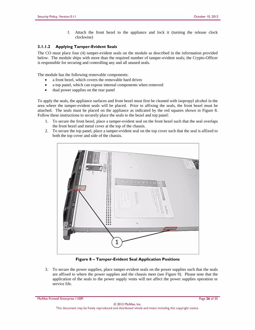
3.1.1.2 Applying Tamper-Evident Seals
The CO must place four (4) tamper-evident seals on the module as described in the information provided
below. The module ships with more than the required number of tamper-evident seals; the Crypto-Officer
is responsible for securing and controlling any and all unused seals.
The module has the following removable components:
a front bezel, which covers the removable hard drives
a top panel, which can expose internal components when removed
dual power supplies on the rear panel
To apply the seals, the appliance surfaces and front bezel must first be cleaned with isopropyl alcohol in the
area where the tamper-evident seals will be placed. Prior to affixing the seals, the front bezel must be
attached. The seals must be placed on the appliance as indicated by the red squares shown in Figure 8.
Follow these instructions to securely place the seals to the bezel and top panel:
1. To secure the front bezel, place a tamper-evident seal on the front bezel such that the seal overlaps
the front bezel and metal cover at the top of the chassis.
2. To secure the top panel, place a tamper-evident seal on the top cover such that the seal is affixed to
both the top cover and side of the chassis.
Figure 8 – Tamper-Evident Seal Application Positions
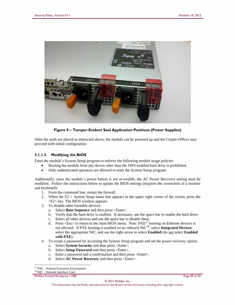
3. To secure the power supplies, place tamper-evident seals on the power supplies such that the seals
are affixed to where the power supplies and the chassis meet (see Figure 9). Please note that the
application of the seals to the power supply vents will not affect the power supplies operation or
service life.
Security Policy, Version 0.11 October 10, 2012
McAfee Firewall Enterprise 1100F Page 27 of 35
© 2012 McAfee, Inc. This document may be freely reproduced and distributed whole and intact including this copyright notice.
Figure 9 – Tamper-Evident Seal Application Positions (Power Supplies)
After the seals are placed as instructed above, the module can be powered up and the Crypto-Officer may
proceed with initial configuration.
3.1.1.3 Modifying the BIOS
Enter the module’s System Setup program to enforce the following module usage policies:
Booting the module from any device other than the FIPS-enabled hard drive is prohibited.
Only authenticated operators are allowed to enter the System Setup program.
Additionally, since the module’s power button is not accessible, the AC Power Recovery setting must be
modified. Follow the instructions below to update the BIOS settings (requires the connection of a monitor
and keyboard):
1. From the command line, restart the firewall.
2. When the F2 = System Setup menu line appears in the upper right corner of the screen, press the
<F2> key. The BIOS window appears.
3. To disable other bootable devices:
a. Select Boot Sequence and then press <Enter>.
b. Verify that the hard drive is enabled. If necessary, use the space bar to enable the hard drive.
c. Select all other devices and use the space bar to disable them.
d. Press <Esc> to return to the main BIOS menu. Note: PXE27
booting on Ethernet devices is
not allowed. If PXE booting is enabled on an onboard NIC28
, select Integrated Devices,
select the appropriate NIC, and use the right arrow to select Enabled (do not select Enabled
with PXE).
4. To create a password for accessing the System Setup program and set the power recovery option:
a. Select System Security and then press <Enter>.
b. Select Setup Password and then press <Enter>.
c. Enter a password and a confirmation and then press <Enter>.
d. Select AC Power Recovery and then press <Enter>.
27 PXE – Preboot Execution Environment 28 NIC – Network Interface Card

Security Policy, Version 0.11 October 10, 2012
McAfee Firewall Enterprise 1100F Page 28 of 35
© 2012 McAfee, Inc. This document may be freely reproduced and distributed whole and intact including this copyright notice.
e. Use the space bar to set AC Power Recovery to “On”.
f. Press <Esc> to return to the main BIOS menu.
5. Press <Esc>, select Save Changes and Exit, and then press <Enter>. The firewall will then
complete its startup process.
3.1.1.4 Confirming the Firmware Version
The cryptographic module requires that proper firmware version be installed. While some models may
have the correct version pre-installed, others may require upgrading. To check if the module is currently
running the correct version, the Crypto-Officer must open the GUI-based Admin Console provided with the
module. Under the software management and manage packages table, the Crypto-Officer can see which
firmware upgrade has been installed along with their versions. If the installed version requires to be
upgraded to a validated version, please follow the steps below.
Upgrading to 7.0.1.03
To perform the upgrade to version 7.0.1.03, the Crypto-Officer must first check the firmware to
ensure they are running version 7.0.1.02. If this version is not running, the Crypto-Officer must
first take measures to upgrade the module to 7.0.1.02. If required, this upgrade can be performed
through Admin Console. If the module is being newly-built from the onboard virtual disk, then
the Crypto-Officer will first need to set up the network configuration and enable the admin
account with a new password.
To upgrade from 7.0.1.02 to 7.0.1.03, the Crypto-Officer must:
1. Under "Software Management / Manage Packages" table, select "70103".
2. Select download.
3. Select install.
4. Verify that the "Manage Packages" tab states that "70103" is installed.
Upgrading to 8.2.0
To perform the upgrade to version 8.2.0, the Crypto-Officer must first check the firmware to
ensure they are running version 8.1.2. If this version is not running, the Crypto-Officer must first
take measures to upgrade the module to 8.1.2. If required, this upgrade can be performed through
Admin Console. If the module is being newly-built from the onboard virtual disk, then the
Crypto-Officer will first need to set up the network configuration and enable the admin account
with a new password.
To upgrade from 8.1.2 to 8.2.0, the Crypto-Officer must:
1. Under "Software Management / Manage Packages" table, select "8.2.0".
2. Select download.
3. Select install.
4. Verify that the "Manage Packages" tab states that "8.2.0" is installed.
3.1.1.5 Setting FIPS Mode Enforcement
Before enforcing FIPS on the module, the Admin Console CO must check that no non-FIPS-Approved
service is running on the module. To view the services that are currently used in enabled rules, select
“Monitor / Service Status”. The Service Status window appears as shown in Figure 10 below. If the
window lists any non-FIPS-Approved protocols (such as telnet as shown below), then those protocols must
be disabled before the module is considered to be in an approved FIPS mode of operation.

Security Policy, Version 0.11 October 10, 2012
McAfee Firewall Enterprise 1100F Page 29 of 35
© 2012 McAfee, Inc. This document may be freely reproduced and distributed whole and intact including this copyright notice.
Figure 10 – Service Status
The process to enable FIPS mode is provided below:
1. Under “Policy/Application Defenses/ Defenses/HTTPS”, disable all non-Approved versions of
SSL, leaving only TLS 1.0 operational.
2. Under “Maintenance / Certificate Management”, ensure that the certificates only use FIPS-
Approved cryptographic algorithms.
3. Select “Maintenance / FIPS”. The FIPS check box appears in the right pane (shown in Figure
11).
4. Select “Enforce U.S. Federal Information Processing Standard”.
5. Save the configuration change.
6. Select “Maintenance / System Shutdown” to reboot the firewall to the Operational kernel to
activate the change.

Security Policy, Version 0.11 October 10, 2012
McAfee Firewall Enterprise 1100F Page 30 of 35
© 2012 McAfee, Inc. This document may be freely reproduced and distributed whole and intact including this copyright notice.
Figure 11 – Configuring For FIPS
Whether the module has been upgraded to a validated firmware version from an earlier firmware, or
shipped with a validated firmware version already present, it is required to delete and recreate all required
cryptographic keys and CSPs necessary for the module's secure operation. The keys and CSPs existing on
the module were generated outside of FIPS mode of operation, and they must now be re-created for use in
FIPS mode. The CO must replace the keys and CSPs listed in Table 13.
Table 13 – Required Keys and CSPs for Secure Operation
Services Cryptographic Keys/CSPs
Admin Console (TLS) Firewall Certificate/private key
Control Center (TLS) Firewall Certificate/private key
HTTPS29 Decryption (TLS) Firewall Certificate/private key
TrustedSource (TLS) Firewall Certificate/private key
Firewall Cluster Management (TLS) Firewall Certificate/private key
Local CA/private key
Passport Authentication (TLS) Firewall Certificate/private key
IPsec/IKE certificate authentication Firewall Certificate/private key
Audit log signing Firewall Certificate/private key
SSH server Firewall Certificate/private key
Administrator Passwords Firewall Certificate/private key
The module is now operating in the FIPS-Approved mode of operation.
29 HTTPS – Hypertext Transfer Protocol Secure

Security Policy, Version 0.11 October 10, 2012
McAfee Firewall Enterprise 1100F Page 31 of 35
© 2012 McAfee, Inc. This document may be freely reproduced and distributed whole and intact including this copyright notice.
3.1.2 Management
The module can run in two different modes: FIPS-Approved and non-FIPS-Approved. While in a FIPS-
Approved mode, only FIPS-Approved and Allowed algorithms may be used. Non-FIPS-Approved services
are disabled in FIPS mode of operation. The Crypto-Officer is able to monitor and configure the module
via the web interface (GUI over TLS), SSH, serial port, or direct-connected keyboard/monitor. Detailed
instructions to monitor and troubleshoot the systems are provided in the Secure Firewall Administration
Guide. The Crypto-Officer should monitor the module’s status regularly for FIPS mode of operation and
active bypass mode. The CO also monitor that only FIPS-Approved algorithms as listed in Table 8 are
being used for TLS and SSH sessions.
The “show status” for FIPS mode of operation can be invoked by determining if the checkbox, shown in
Figure 11, is checked. The “show status” service as it pertains to bypass is shown in the GUI under VPN
Definitions and the module column. For the CLI, the Crypto-Officer may enter “cf ipsec q type=bypass”
to get a listing of the existing bypass rules.
If any irregular activity is noticed or the module is consistently reporting errors, then McAfee customer
support should be contacted.
3.1.3 Zeroization
In order to zeroize the module of all keys and CSPs, it is necessary to first rebuild the module’s image
essentially wiping out all data from the module; the rebuild must be performed by McAfee. Once a factory
reset has been performed, default keys and CSPs will be set up as part of the renewal process. These keys
must be recreated as per the instructions found in Table 13. Failure to recreate these keys will result in a
non-compliant module.
For more information about resetting the module to a factory default, please consult the documentation that
shipped with the module.
3.1.4 Disabling FIPS Mode of Operation
To take the module out of FIPS mode of operation, the Crypto-Officer must zeroize the CSPs as described
in section 3.1.3 of this document. FIPS mode can be disabled from Admin Console window:
1. Select “Maintenance / FIPS”. The FIPS check box appears in the right pane.
2. Unselect “Enforce U.S. Federal Information Processing Standard” (shown in Figure 11).
3. Save the configuration change.
4. Select “Maintenance / System Shutdown” and reboot the firewall to the Operational kernel to
activate the change.
3.2 User Guidance
When using key establishment protocols (RSA and DH) in the FIPS-Approved mode, the User is
responsible for selecting a key size that provides the appropriate level of key strength for the key being
transported.
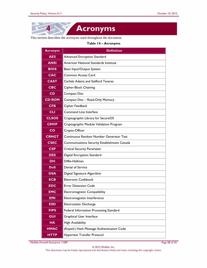
Security Policy, Version 0.11 October 10, 2012
McAfee Firewall Enterprise 1100F Page 32 of 35
© 2012 McAfee, Inc. This document may be freely reproduced and distributed whole and intact including this copyright notice.
4 Acronyms This section describes the acronyms used throughout the document.
Table 14 – Acronyms
Acronym Definition
AES Advanced Encryption Standard
ANSI American National Standards Institute
BIOS Basic Input/Output System
CAC Common Access Card
CAST Carlisle Adams and Stafford Tavares
CBC Cipher-Block Chaining
CD Compact Disc
CD-ROM Compact Disc – Read-Only Memory
CFB Cipher Feedback
CLI Command Line Interface
CLSOS Cryptographic Library for SecureOS
CMVP Cryptographic Module Validation Program
CO Crypto-Officer
CRNGT Continuous Random Number Generator Test
CSEC Communications Security Establishment Canada
CSP Critical Security Parameter
DES Digital Encryption Standard
DH Diffie-Hellman
DoS Denial of Service
DSA Digital Signature Algorithm
ECB Electronic Codebook
EDC Error Detection Code
EMC Electromagnetic Compatibility
EMI Electromagnetic Interference
ESD Electrostatic Discharge
FIPS Federal Information Processing Standard
GUI Graphical User Interface
HA High Availability
HMAC (Keyed-) Hash Message Authentication Code
HTTP Hypertext Transfer Protocol
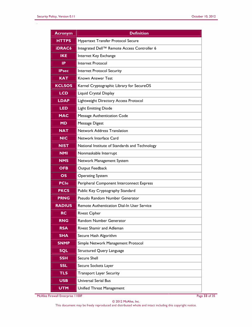
Security Policy, Version 0.11 October 10, 2012
McAfee Firewall Enterprise 1100F Page 33 of 35
© 2012 McAfee, Inc. This document may be freely reproduced and distributed whole and intact including this copyright notice.
Acronym Definition
HTTPS Hypertext Transfer Protocol Secure
iDRAC6 Integrated Dell™ Remote Access Controller 6
IKE Internet Key Exchange
IP Internet Protocol
IPsec Internet Protocol Security
KAT Known Answer Test
KCLSOS Kernel Cryptographic Library for SecureOS
LCD Liquid Crystal Display
LDAP Lightweight Directory Access Protocol
LED Light Emitting Diode
MAC Message Authentication Code
MD Message Digest
NAT Network Address Translation
NIC Network Interface Card
NIST National Institute of Standards and Technology
NMI Nonmaskable Interrupt
NMS Network Management System
OFB Output Feedback
OS Operating System
PCIe Peripheral Component Interconnect Express
PKCS Public Key Cryptography Standard
PRNG Pseudo Random Number Generator
RADIUS Remote Authentication Dial-In User Service
RC Rivest Cipher
RNG Random Number Generator
RSA Rivest Shamir and Adleman
SHA Secure Hash Algorithm
SNMP Simple Network Management Protocol
SQL Structured Query Language
SSH Secure Shell
SSL Secure Sockets Layer
TLS Transport Layer Security
USB Universal Serial Bus
UTM Unified Threat Management

Security Policy, Version 0.11 October 10, 2012
McAfee Firewall Enterprise 1100F Page 34 of 35
© 2012 McAfee, Inc. This document may be freely reproduced and distributed whole and intact including this copyright notice.
Acronym Definition
VGA Video Graphics Array
VPN Virtual Private Network

Prepared by: Corsec Security, Inc.
13135 Lee Jackson Memorial Hwy, Suite 220 Fairfax, VA 22033
United States of America
Phone: +1 (703) 267-6050 Email: [email protected] http://www.corsec.com