Mca i-u-2-overview of register transfer, micro operations and basic computer organization and design
61
Overview of Register Transfer, Micro Operations and Basic Computer Organization and Design Course: MCA-I Subject: Computer Organization And Architecture Unit-2 1
-
Upload
rai-university -
Category
Education
-
view
39 -
download
0
Transcript of Mca i-u-2-overview of register transfer, micro operations and basic computer organization and design
Overview of Register Transfer, Micro Operations and Basic
Computer Organization and Design
Course: MCA-ISubject: Computer Organization
And Architecture Unit-2
1
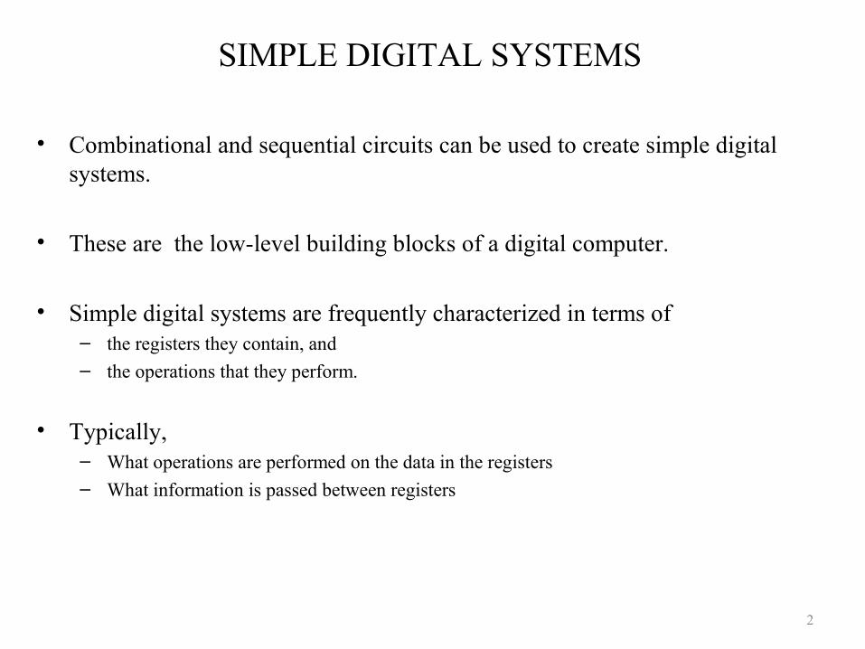
SIMPLE DIGITAL SYSTEMS
• Combinational and sequential circuits can be used to create simple digital systems.
• These are the low-level building blocks of a digital computer.
• Simple digital systems are frequently characterized in terms of– the registers they contain, and
– the operations that they perform.
• Typically,– What operations are performed on the data in the registers
– What information is passed between registers
2
MICROOPERATIONS (1)
• The operations on the data in registers are called microoperations.
• The functions built into registers are examples of microoperations– Shift
– Load
– Clear
– Increment
3
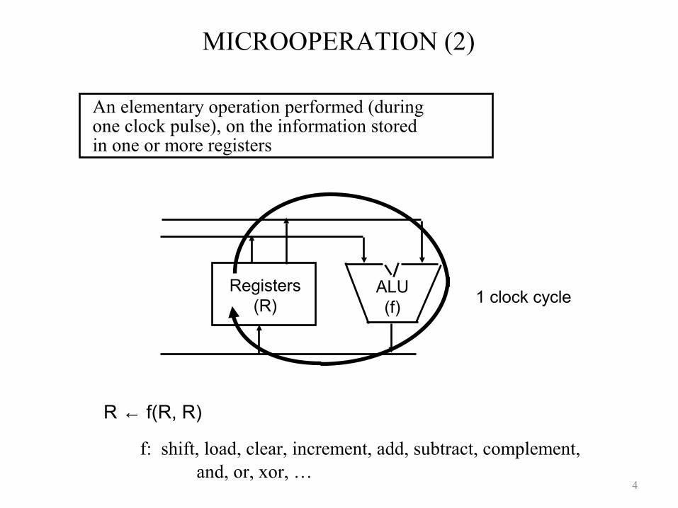
MICROOPERATION (2)
An elementary operation performed (during one clock pulse), on the information stored in one or more registers
R ← f(R, R)
f: shift, load, clear, increment, add, subtract, complement,and, or, xor, …
ALU(f)
Registers(R) 1 clock cycle
4
ORGANIZATION OF A DIGITAL SYSTEM
- Set of registers and their functions
- Microoperations set
Set of allowable microoperations provided by the organization of the computer
- Control signals that initiate the sequence of microoperations (to perform the functions)
• Definition of the (internal) organization of a computer
5
REGISTER TRANSFER LEVEL
• Viewing a computer, or any digital system, in this way is called the register transfer level
• This is because we’re focusing on– The system’s registers
– The data transformations in them, and
– The data transfers between them.
6
REGISTER TRANSFER LANGUAGE
• Rather than specifying a digital system in words, a specific notation is used, register transfer language
• For any function of the computer, the register transfer language can be used to describe the (sequence of) microoperations
• Register transfer language– A symbolic language
– A convenient tool for describing the internal organization of digital computers
– Can also be used to facilitate the design process of digital systems.
7
DESIGNATION OF REGISTERS
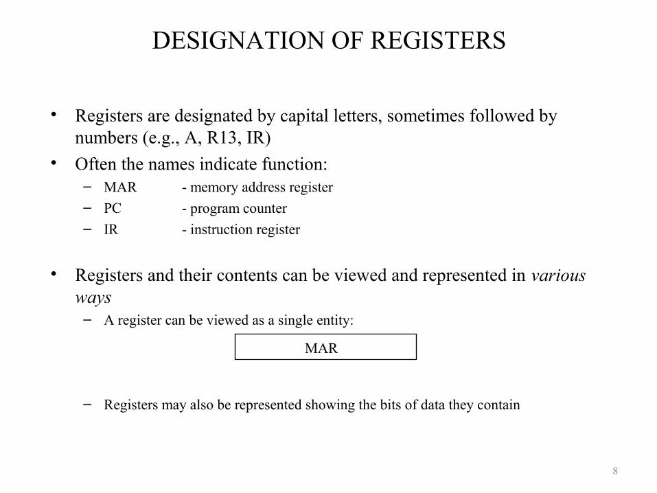
• Registers are designated by capital letters, sometimes followed by numbers (e.g., A, R13, IR)
• Often the names indicate function:– MAR - memory address register
– PC - program counter
– IR - instruction register
• Registers and their contents can be viewed and represented in various ways
– A register can be viewed as a single entity:
– Registers may also be represented showing the bits of data they contain
MAR
8
DESIGNATION OF REGISTERS
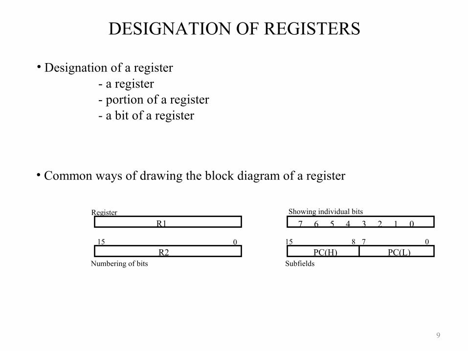
R1 Register
Numbering of bits
Showing individual bits
SubfieldsPC(H) PC(L)
15 8 7 0
- a register - portion of a register - a bit of a register
• Common ways of drawing the block diagram of a register
7 6 5 4 3 2 1 0
R215 0
• Designation of a register
9
REGISTER TRANSFER
• Copying the contents of one register to another is a register transfer
• A register transfer is indicated as
R2 ← R1
– In this case the contents of register R1 are copied (loaded) into register R2
– A simultaneous transfer of all bits from the source R1 to the destination register R2, during one clock pulse
– Note that this is a non-destructive; i.e. the contents of R1 are not altered by copying (loading) them to R2
10
REGISTER TRANSFER
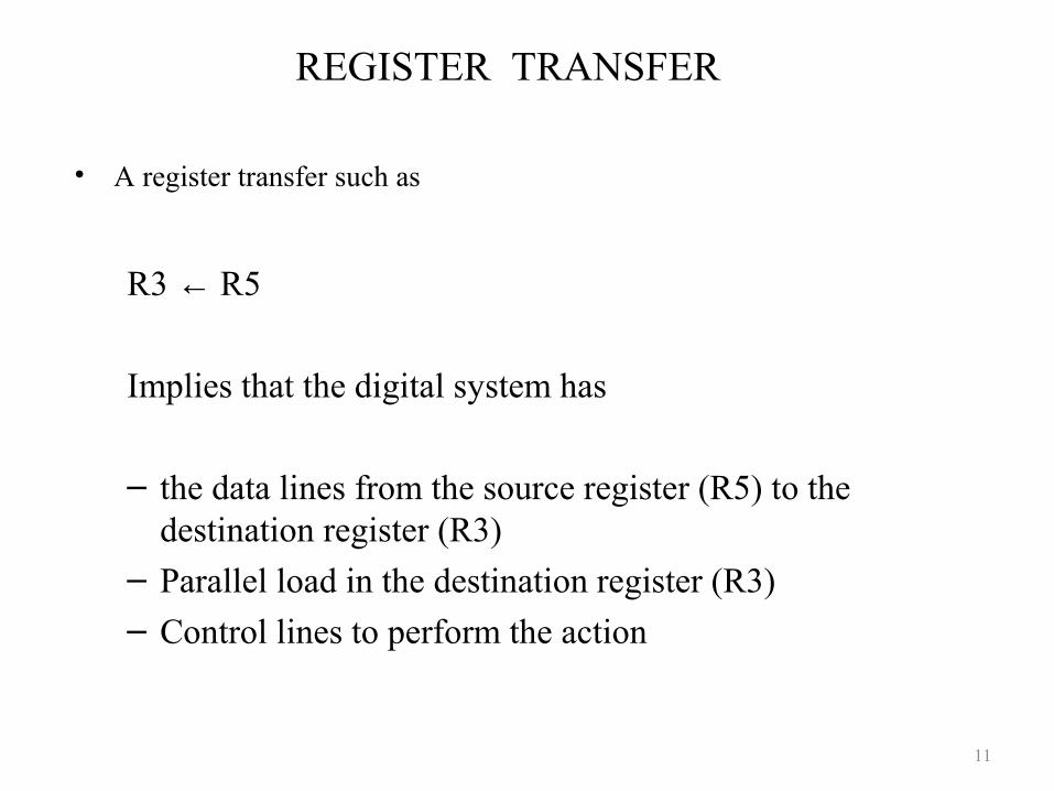
• A register transfer such as
R3 ← R5
Implies that the digital system has
– the data lines from the source register (R5) to the destination register (R3)
– Parallel load in the destination register (R3)
– Control lines to perform the action
11
CONTROL FUNCTIONS
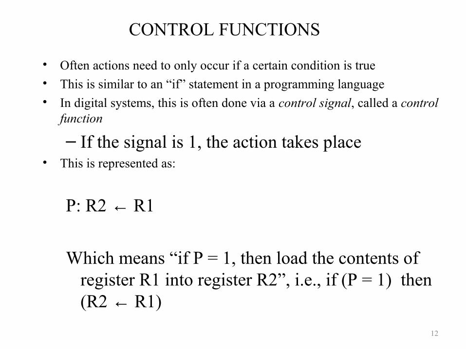
• Often actions need to only occur if a certain condition is true
• This is similar to an “if” statement in a programming language
• In digital systems, this is often done via a control signal, called a control function
– If the signal is 1, the action takes place• This is represented as:
P: R2 ← R1
Which means “if P = 1, then load the contents of register R1 into register R2”, i.e., if (P = 1) then (R2 ← R1)
12
HARDWARE IMPLEMENTATION OF CONTROLLED TRANSFERS
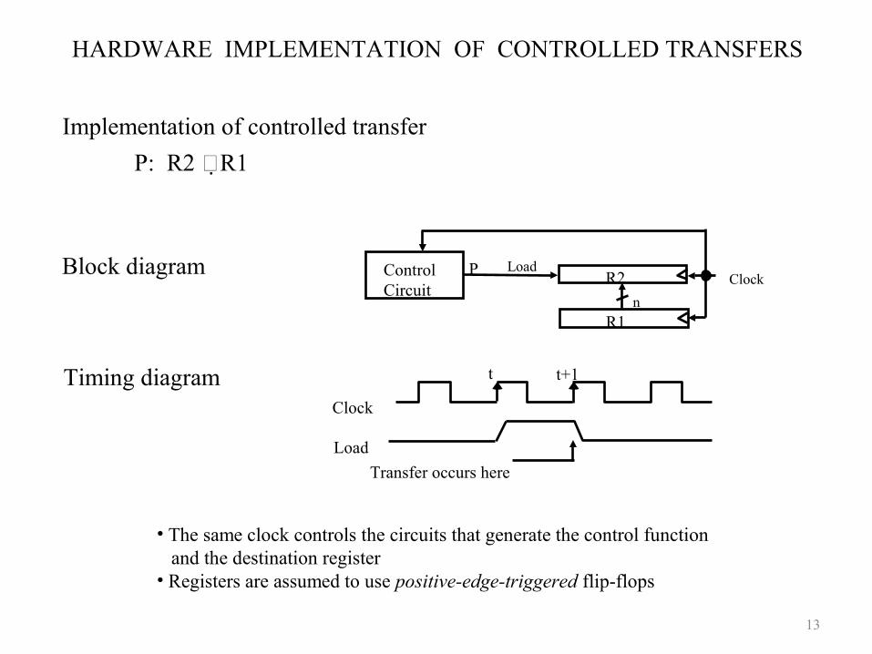
Implementation of controlled transfer
P: R2 R1
Block diagram
Timing diagram
Clock
Transfer occurs here
R2
R1
Control Circuit
LoadP
n
Clock
Load
t t+1
• The same clock controls the circuits that generate the control function and the destination register• Registers are assumed to use positive-edge-triggered flip-flops
13
SIMULTANEOUS OPERATIONS
• If two or more operations are to occur simultaneously, they are separated with commas
P: R3 ← R5, MAR ← IR
• Here, if the control function P = 1, load the contents of R5 into R3, and at the same time (clock), load the contents of register IR into register MAR
14
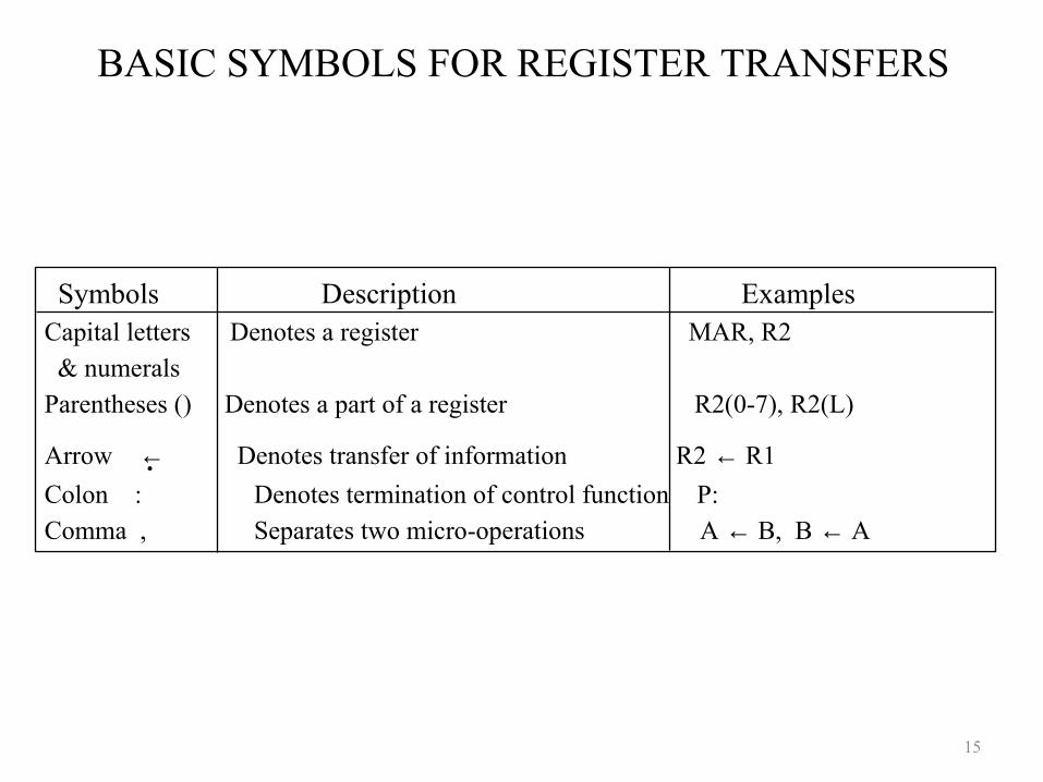
BASIC SYMBOLS FOR REGISTER TRANSFERS
Capital letters Denotes a register MAR, R2 & numerals Parentheses () Denotes a part of a register R2(0-7), R2(L)
Arrow ← Denotes transfer of information R2 ← R1
Colon : Denotes termination of control function P:Comma , Separates two micro-operations A ← B, B ← A
Symbols Description Examples
15
CONNECTING REGISTRS
• In a digital system with many registers, it is impractical to have data and control lines to directly allow each register to be loaded with the contents of every possible other registers
• To completely connect n registers n(n-1) lines
• O(n2) cost– This is not a realistic approach to use in a large digital system
• Instead, take a different approach
• Have one centralized set of circuits for data transfer – the bus
• Have control circuits to select which register is the source, and which is the destination
16
Micro-Operations
A micro-operation is an elementary operation, performed during one clock pulse, on the information stored in one or more registers.R1 ← R1 + R2
17
Computer Organization
The organization of a digital computer is best defined by specifying:– The set of registers it contains and their function– The sequence of micro-operations performed on
the binary information stored in the registers– The control functions that initiate the sequence
of micro-operations
18
Register Designation
• Whole register
• Portion of a register
• One bit in a register
19 /
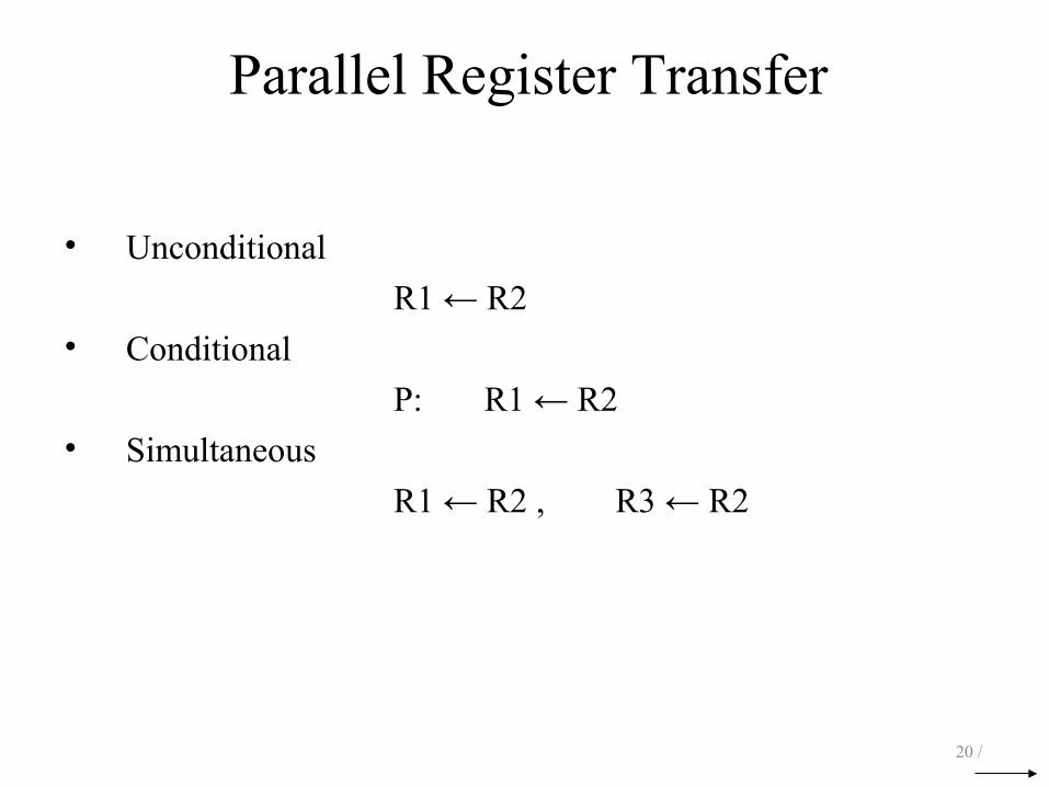
Parallel Register Transfer
• Unconditional
R1 ← R2
• Conditional
P: R1 ← R2
• Simultaneous
R1 ← R2 , R3 ← R2
20 /
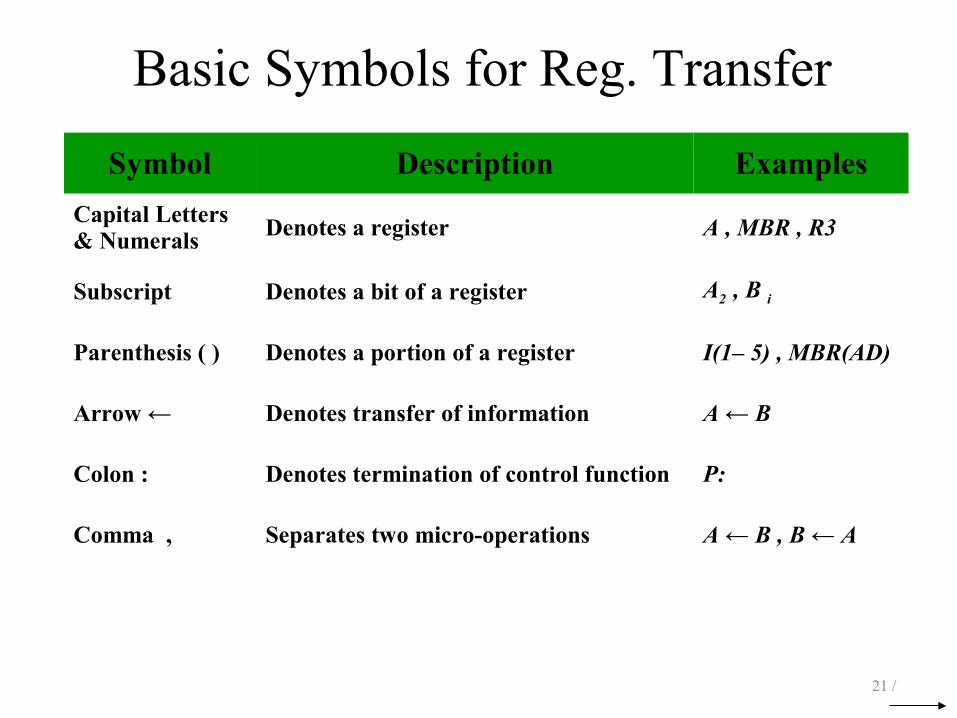
Basic Symbols for Reg. Transfer
21 /
Symbol Description Examples
Capital Letters & Numerals Denotes a register A , MBR , R3
Subscript Denotes a bit of a register A2 , B i
Parenthesis ( ) Denotes a portion of a register I(1– 5) , MBR(AD)
Arrow ← Denotes transfer of information A ← B
Colon : Denotes termination of control function P:
Comma , Separates two micro-operations A ← B , B ← A
Serial Register Transfer
S: A i ← A i – 1 , A 0 ← 0 i = 1, 2, 3
22 /

Bus Transfer
23 /

Bus Transfer
24 /

Bus Transfer
25 /

Bus Transfer
26 /

Bus Transfer
27 /
Bus Transfer
28 /
Memory Transfer
MBR ← MM ← MBR
29 /
Memory Transfer
MBR ← MMBR ← M [ R1 ]
30 /
Micro-Operation Summary
31 /
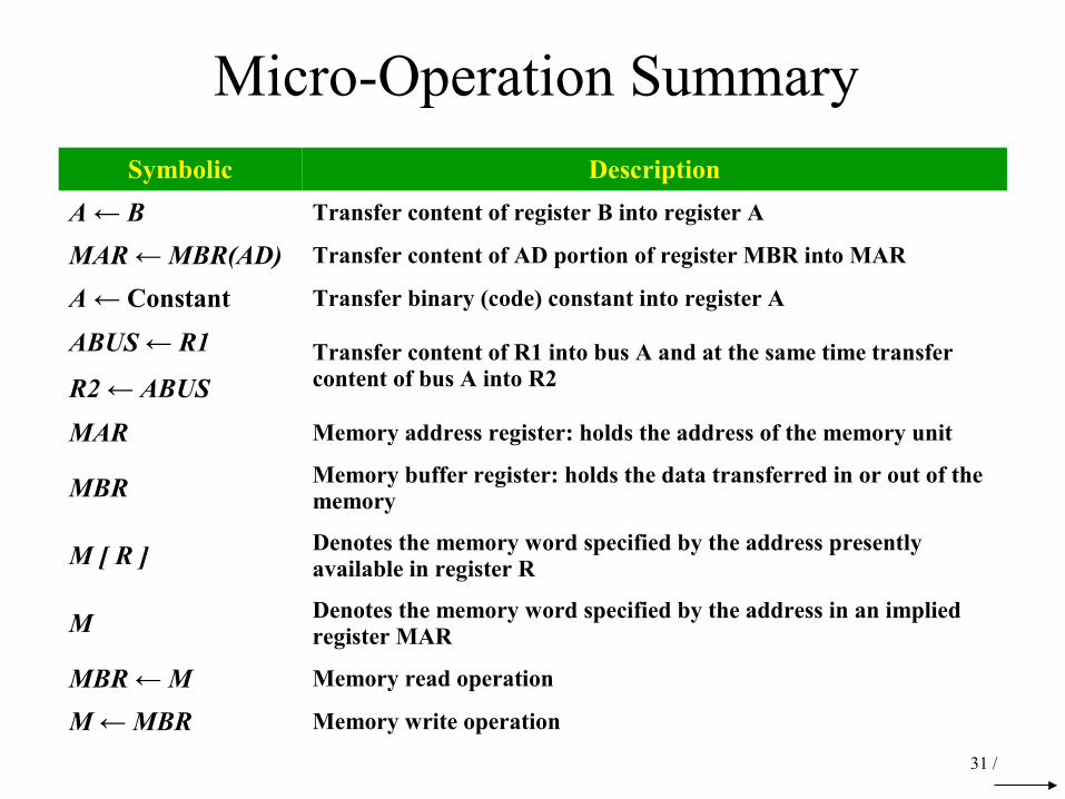
Symbolic Description
A ← B Transfer content of register B into register A
MAR ← MBR(AD) Transfer content of AD portion of register MBR into MAR
A ← Constant Transfer binary (code) constant into register A
ABUS ← R1
R2 ← ABUS
Transfer content of R1 into bus A and at the same time transfer content of bus A into R2
MAR Memory address register: holds the address of the memory unit
MBR Memory buffer register: holds the data transferred in or out of the memory
M [ R ] Denotes the memory word specified by the address presently available in register R
M Denotes the memory word specified by the address in an implied register MAR
MBR ← M Memory read operation
M ← MBR Memory write operation
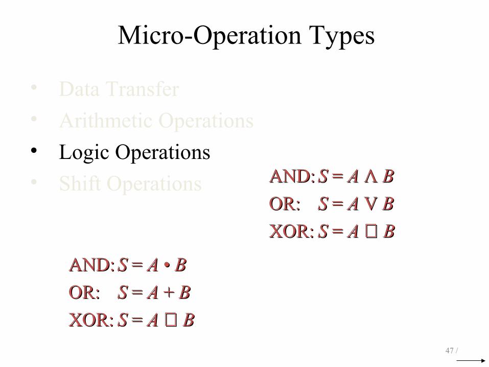
Micro-Operation Types
• Data Transfer
• Arithmetic Operations
• Logic Operations
• Shift Operations
32 /
Micro-Operation Types
• Data Transfer
• Arithmetic Operations S = A + B
• Logic Operations
• Shift Operations
33 /
Addition
S = A + B
34 /
Time (Propagation) delay = ?Time (Propagation) delay = ?

Addition
S = A + B
t = 0
35 /
Time (Propagation) delay = ?Time (Propagation) delay = ?

Addition
S = A + B
t = τ
36 /
Time (Propagation) delay = ?Time (Propagation) delay = ?
Addition
S = A + B
t = 2τ
37 /
Time (Propagation) delay = ?Time (Propagation) delay = ?

Addition
S = A + B
t = 3τ
38 /
Time (Propagation) delay = ?Time (Propagation) delay = ?
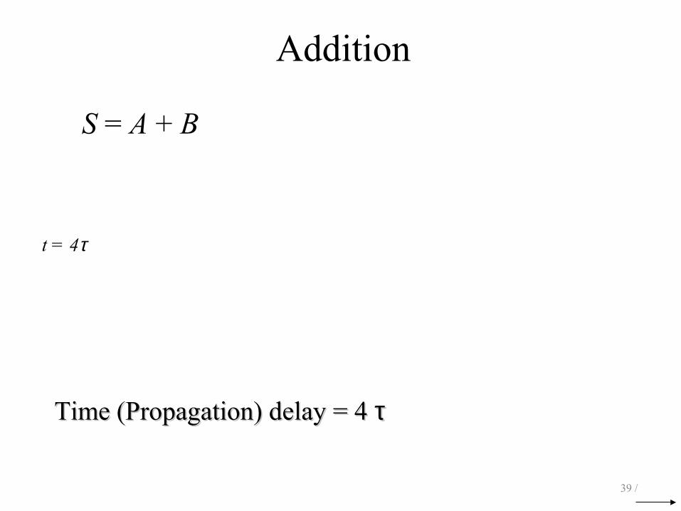
Addition
S = A + B
t = 4τ
39 /
Time (Propagation) delay = 4 Time (Propagation) delay = 4 ττ
Addition
EA ← A + B
40 /
FlagFlag
Subtraction
A ← A – B _
A ← A + ( B + 1 )
41 /
Increment
A ← A + 1
42 /
Decrement
A ← A – 1
43 /
Arithmetic
44 /
Arithmetic
45 /
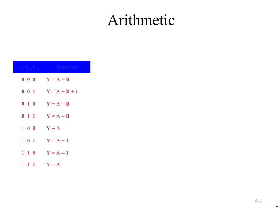
C2 C1 C0 Function
0 0 0 Y = A + B
0 0 1 Y = A + B + 1
0 1 0 Y = A + B
0 1 1 Y = A – B
1 0 0 Y = A
1 0 1 Y = A + 1
1 1 0 Y = A – 1
1 1 1 Y = A
Arithmetic
46 /
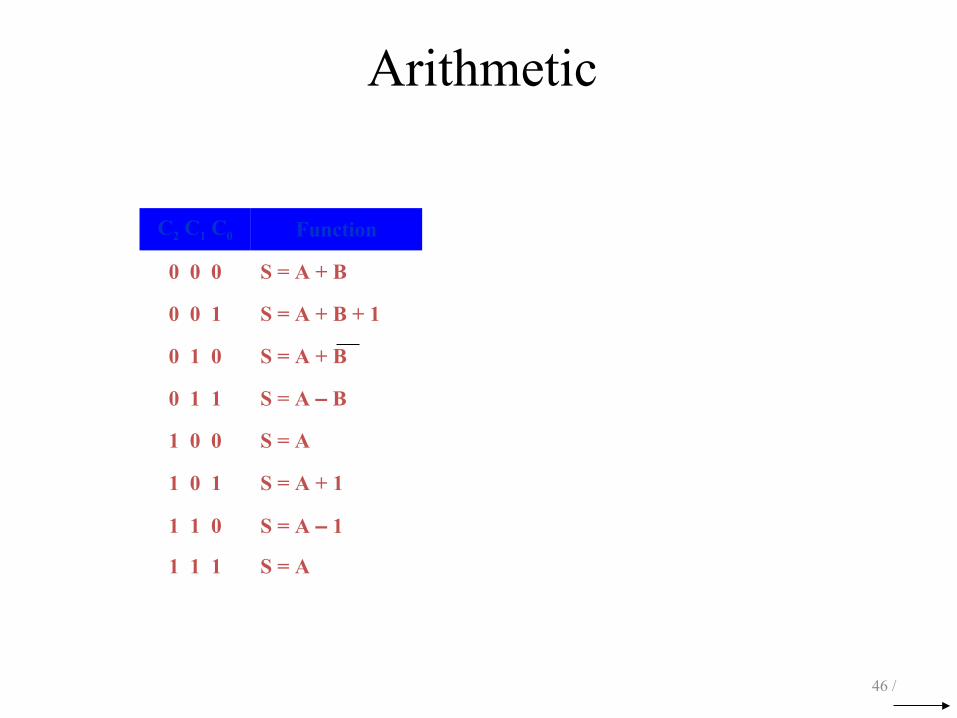
C2 C1 C0 Function
0 0 0 S = A + B
0 0 1 S = A + B + 1
0 1 0 S = A + B
0 1 1 S = A – B
1 0 0 S = A
1 0 1 S = A + 1
1 1 0 S = A – 1
1 1 1 S = A
Micro-Operation Types
• Data Transfer
• Arithmetic Operations
• Logic Operations
• Shift Operations
47 /
AND:AND: SS = = AA ΛΛ BB
OR:OR: SS = = AA V V BB
XOR:XOR: SS = = AA ⊕⊕ BB
AND:AND: SS = = AA • • BB
OR:OR: SS = = AA + + BB
XOR:XOR: SS = = AA ⊕⊕ BB
Logic
48 /

Logic
49 /
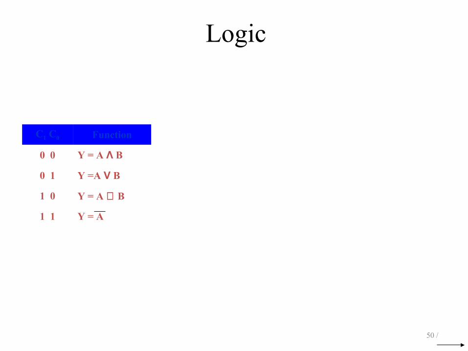
Logic
50 /
C1 C0 Function
0 0 Y = A Λ B
0 1 Y =A V B
1 0 Y = A ⊕ B
1 1 Y = A
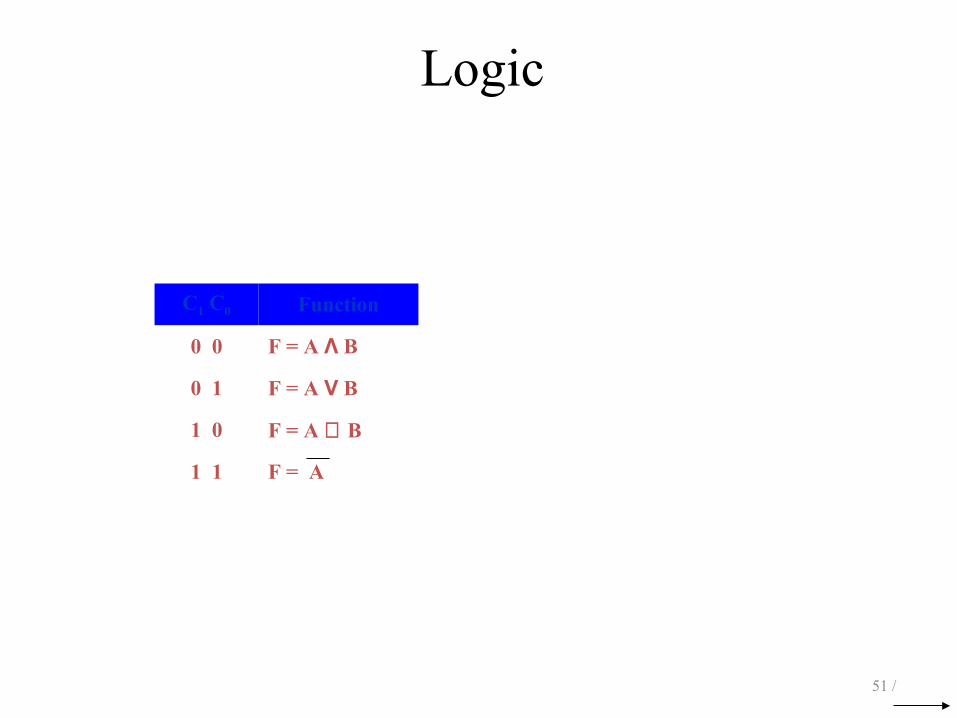
Logic
51 /
C1 C0 Function
0 0 F = A Λ B
0 1 F = A V B
1 0 F = A ⊕ B
1 1 F = A
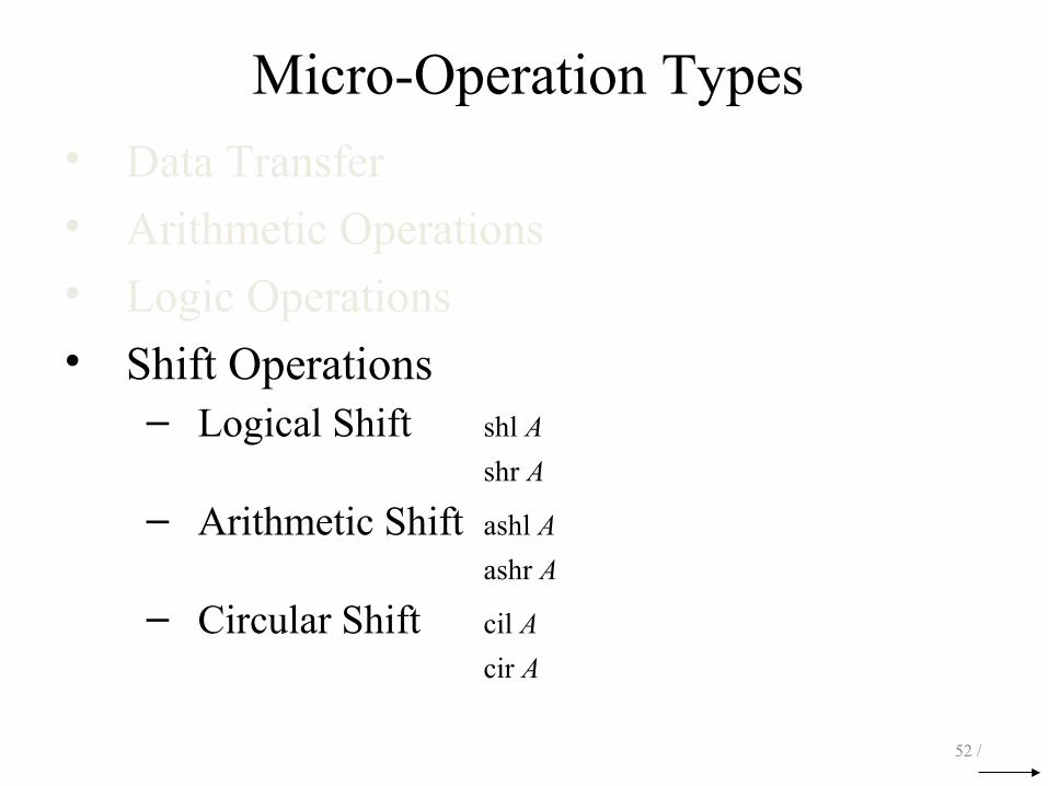
Micro-Operation Types• Data Transfer
• Arithmetic Operations
• Logic Operations
• Shift Operations– Logical Shift shl A
shr A
– Arithmetic Shift ashl A
ashr A
– Circular Shift cil A
cir A
52 /
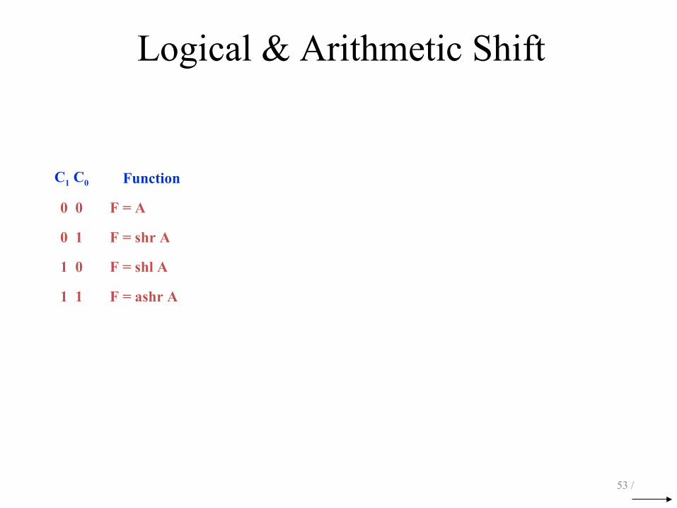
Logical & Arithmetic Shift
53 /
C1 C0 Function
0 0 F = A
0 1 F = shr A
1 0 F = shl A
1 1 F = ashr A
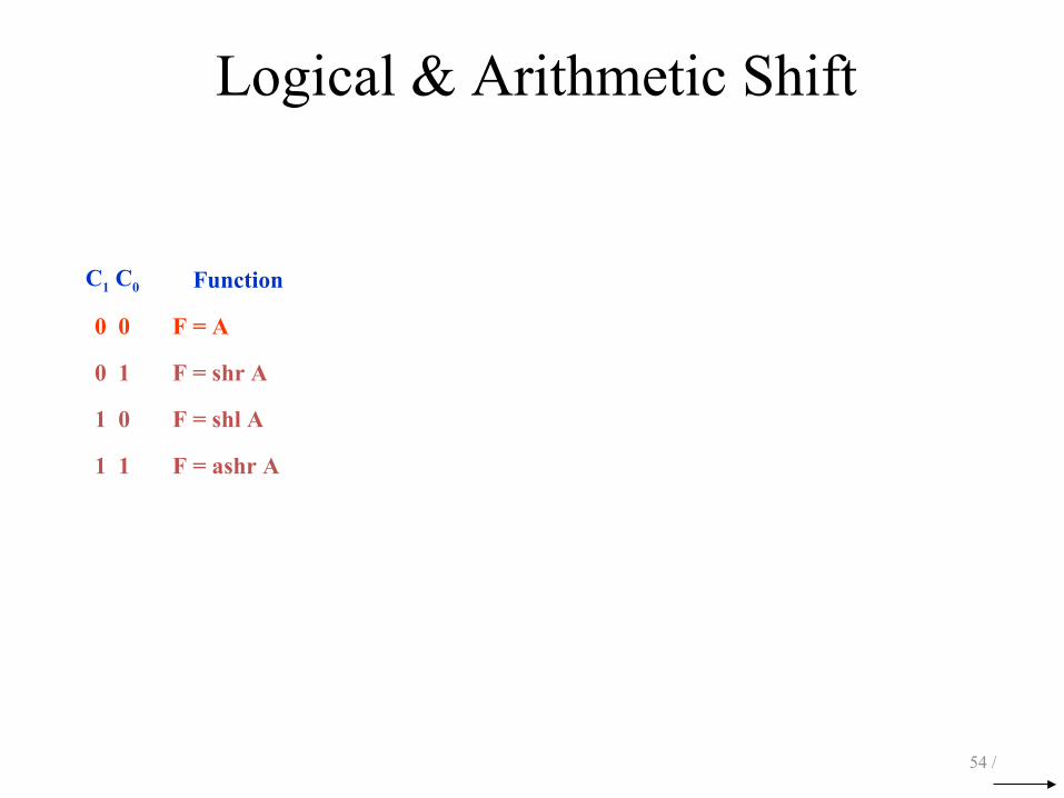
Logical & Arithmetic Shift
54 /
C1 C0 Function
0 0 F = A
0 1 F = shr A
1 0 F = shl A
1 1 F = ashr A

Logical & Arithmetic Shift
55 /
C1 C0 Function
0 0 F = A
0 1 F = shr A
1 0 F = shl A
1 1 F = ashr A

Logical & Arithmetic Shift
56 /
C1 C0 Function
0 0 F = A
0 1 F = shr A
1 0 F = shl A
1 1 F = ashr A

Logical & Arithmetic Shift
57 /
C1 C0 Function
0 0 F = A
0 1 F = shr A
1 0 F = shl A
1 1 F = ashr A
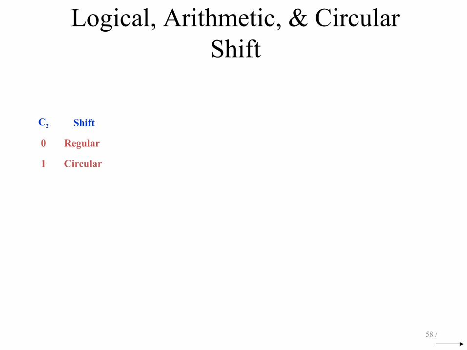
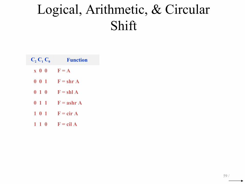
Logical, Arithmetic, & Circular Shift
58 /
C2 Shift
0 Regular
1 Circular
Logical, Arithmetic, & Circular Shift
59 /
C2 C1 C0 Function
x 0 0 F = A
0 0 1 F = shr A
0 1 0 F = shl A
0 1 1 F = ashr A
1 0 1 F = cir A
1 1 0 F = cil A
Arithmetic and Logic Unit (ALU)
60 /
Reference
Reference Book
• Computer Organization & Architecture 7e By Stallings
• Computer System Architecture By Mano