Maximum Torque per Ampere Control Using Hill...
10
Maximum Torque per Ampere Control Using Hill Climbing Method Without Motor Parameters Based on V/f Control Jun-ichi Itoh, Takato Toi, Masakazu Kato Nagaoka University of Technology 1603-1 Kamitomioka-cho Nagaoka city Niigata, Japan Tel., Fax: +81 / (258) – 47.9533. E-Mail: [email protected], [email protected], [email protected] URL: http://itohserver01.nagaokaut.ac.jp/itohlab/index.html Keywords «Permanent magnet motor», «Sensorless control» Abstract This paper proposes novel V/f control for interior permanent-magnet synchronous motors (IPMSMs) in order to achieve maximum torque per ampere (MTPA) control without motor parameters such as dq-axis inductance and flux linkage of a permanent magnet. The V/f control does not require either information of a rotor position or the motor parameters in order to construct the control system. However, the conventional MTPA control requires the motor parameters because the control determines the compensation voltage depending on the reactive power. On the other hand, with the proposed MTPA control, a hill climbing method is utilized. The proposed MTPA control calculates the compensation voltage depending on the output current in order to track the MTPA control point without the motor parameters. The validity of the proposed method is confirmed by the experimental results using a 3.7-kW IPMSM. From the experimental results, the magnitude of the phase current is decreased by 56% at the rated speed. Furthermore, the proposed MTPA control is effective regardless of the magnitude of the load torque. I. Introduction Recently, IPMSMs are widely applied to industry applications due to the attractive features; high power density, high efficiency and robust structure [1]-[3].There are basically two IPMSM control methods: field oriented control (FOC) and V/f control [4]. In the FOC, the identification of the pole position is necessary. Therefore, a position sensor is used to detect the pole position. However, it is impossible to use the position sensors in applications where such as a motor and a load are built-in systems. As a result, many sensorless FOC have been studied [5]-[10]. The sensorless FOC requires some motor parameters. When the motor parameters are fluctuated and different from the nominal values, it is necessary to measure the motor parameters or estimate them in the sensorless FOC [11]. In addition, in order to drive IPMSMs efficiently, MTPA control is widely applied. The MTPA control based on the FOC have been studied by using various methods such as injecting the current signal, estimating the maximum torque control frame or the motor parameters, and on-line estimation [12]-[14]. However, these methods as mentioned above require the motor parameters such as d-axis inductance, q-axis inductance and magnetic flux linkage of the permanent magnet. When the estimated motor parameters are different from the actual values, the output current does not become the minimum in the MTPA control based on the sensorless FOC because the estimated coordinate axes deviate from the actual dq-axis. On the other hand, the V/f control does not require the identification of the pole position because the control depends on the frame which is calculated in the controller of the inverter. In addition, the motor parameters are basically not used in the V/f control. Some MTPA control based on the V/f control by controlling the current phase or the reactive power have been proposed [15][16]. However,
Transcript of Maximum Torque per Ampere Control Using Hill...
Maximum Torque per Ampere Control Using Hill Climbing Method
Without Motor Parameters Based on V/f Control
Jun-ichi Itoh, Takato Toi, Masakazu Kato
Nagaoka University of Technology
1603-1 Kamitomioka-cho
Nagaoka city Niigata, Japan
Tel., Fax: +81 / (258) – 47.9533.
E-Mail: [email protected], [email protected], [email protected]
URL: http://itohserver01.nagaokaut.ac.jp/itohlab/index.html
Keywords
«Permanent magnet motor», «Sensorless control»
Abstract
This paper proposes novel V/f control for interior permanent-magnet synchronous motors
(IPMSMs) in order to achieve maximum torque per ampere (MTPA) control without motor parameters
such as dq-axis inductance and flux linkage of a permanent magnet. The V/f control does not require
either information of a rotor position or the motor parameters in order to construct the control system.
However, the conventional MTPA control requires the motor parameters because the control
determines the compensation voltage depending on the reactive power. On the other hand, with the
proposed MTPA control, a hill climbing method is utilized. The proposed MTPA control calculates
the compensation voltage depending on the output current in order to track the MTPA control point
without the motor parameters. The validity of the proposed method is confirmed by the experimental
results using a 3.7-kW IPMSM. From the experimental results, the magnitude of the phase current is
decreased by 56% at the rated speed. Furthermore, the proposed MTPA control is effective regardless
of the magnitude of the load torque.
I. Introduction
Recently, IPMSMs are widely applied to industry applications due to the attractive features; high
power density, high efficiency and robust structure [1]-[3].There are basically two IPMSM control
methods: field oriented control (FOC) and V/f control [4].
In the FOC, the identification of the pole position is necessary. Therefore, a position sensor is used
to detect the pole position. However, it is impossible to use the position sensors in applications where
such as a motor and a load are built-in systems. As a result, many sensorless FOC have been studied
[5]-[10]. The sensorless FOC requires some motor parameters. When the motor parameters are
fluctuated and different from the nominal values, it is necessary to measure the motor parameters or
estimate them in the sensorless FOC [11]. In addition, in order to drive IPMSMs efficiently, MTPA
control is widely applied. The MTPA control based on the FOC have been studied by using various
methods such as injecting the current signal, estimating the maximum torque control frame or the
motor parameters, and on-line estimation [12]-[14]. However, these methods as mentioned above
require the motor parameters such as d-axis inductance, q-axis inductance and magnetic flux linkage
of the permanent magnet. When the estimated motor parameters are different from the actual values,
the output current does not become the minimum in the MTPA control based on the sensorless FOC
because the estimated coordinate axes deviate from the actual dq-axis.
On the other hand, the V/f control does not require the identification of the pole position because the
control depends on the frame which is calculated in the controller of the inverter. In addition, the
motor parameters are basically not used in the V/f control. Some MTPA control based on the V/f
control by controlling the current phase or the reactive power have been proposed [15][16]. However,
the motor parameters are required in these MTPA control. Therefore, the MTPA control using the
motor parameters spoils the advantage of the V/f control.
This paper proposes the MTPA control for the V/f control with a hill climbing method in order to
achieve the MTPA control without the motor parameters. It is noted that the MTPA control using the
hill climbing method is not effective in the sensorless FOC because the sensorless FOC requires the
motor parameters in the control strategy. In addition, the variation of the d-axis current by the hill
climbing method disturbs the position estimation system. This paper will be organized as follows; first,
the principles of the V/f control is introduced. Next, the MTPA control based on the hill climbing
method is explained. Finally, the experimental results are shown to confirm the validity and the
effectiveness of the proposed method.
II. Maximum torque per ampere control method based on V/f control
A. V/f control
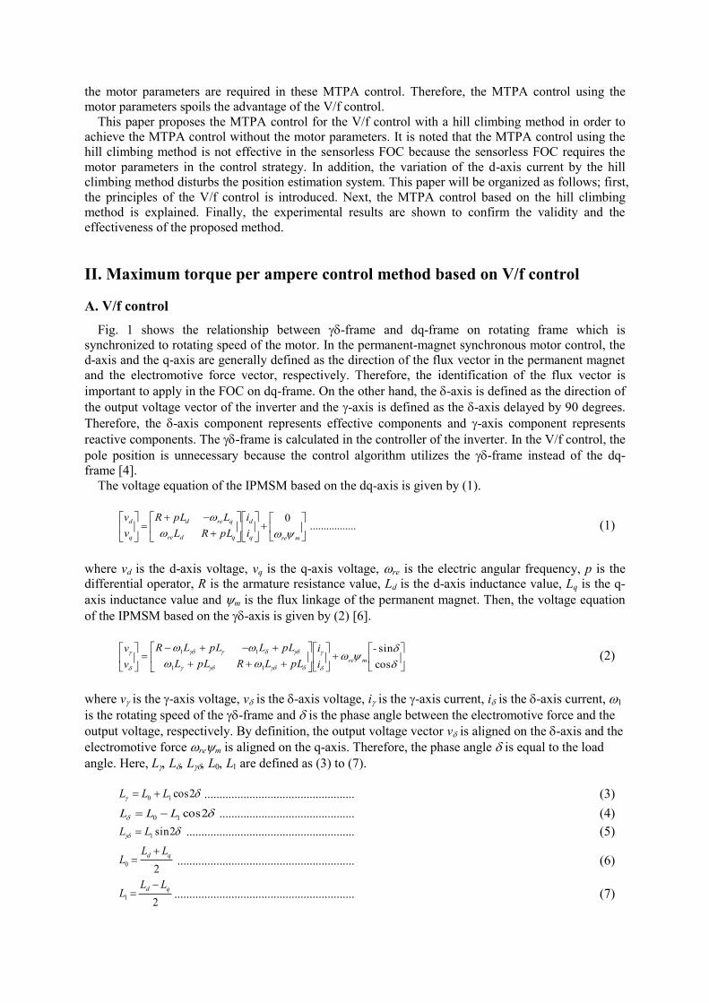
Fig. 1 shows the relationship between -frame and dq-frame on rotating frame which is
synchronized to rotating speed of the motor. In the permanent-magnet synchronous motor control, the
d-axis and the q-axis are generally defined as the direction of the flux vector in the permanent magnet
and the electromotive force vector, respectively. Therefore, the identification of the flux vector is
important to apply in the FOC on dq-frame. On the other hand, the -axis is defined as the direction of
the output voltage vector of the inverter and the -axis is defined as the -axis delayed by 90 degrees.
Therefore, the -axis component represents effective components and -axis component represents
reactive components. The -frame is calculated in the controller of the inverter. In the V/f control, the
pole position is unnecessary because the control algorithm utilizes the -frame instead of the dq-
frame [4].
The voltage equation of the IPMSM based on the dq-axis is given by (1).
mreq
d
qdre
qred
q
d
i
i
pLRL
LpLR
v
v
0 ................. (1)
where vd is the d-axis voltage, vq is the q-axis voltage, re is the electric angular frequency, p is the
differential operator, R is the armature resistance value, Ld is the d-axis inductance value, Lq is the q-
axis inductance value and m is the flux linkage of the permanent magnet. Then, the voltage equation
of the IPMSM based on the -axis is given by (2) [6].
cos
sin
11
11 -
i
i
pLLRpLL
pLLpLLR
v
vmre (2)
where v is the -axis voltage, v is the -axis voltage, i is the -axis current, i is the -axis current, 1
is the rotating speed of the -frame and is the phase angle between the electromotive force and the
output voltage, respectively. By definition, the output voltage vector v is aligned on the -axis and the
electromotive force rem is aligned on the q-axis. Therefore, the phase angle is equal to the load
angle. Here, LLLLLare defined as (3) to (7).
2cos10 LLL .................................................. (3)
2cos10 LLL ............................................. (4)
2sin1LL ........................................................ (5)
20
qd LLL
........................................................... (6)
21
qd LLL
............................................................ (7)
The relationship between the -axis current and the dq-axis current is given by (8) using the phase
angle .
cossin
sincos
iii
iii
q
d
..................................................... (8)
The output torque of the IPMSM and the relationship between the electrical angular velocity and the
output torque are expressed by (9) and (10), respectively. It is noted that the viscosity resistance is
ignored.
})({ qdqdqmf iiLLiPT ........................................ (9)
J
TTPp
Lf
re
............................................................. (10)
where Pf is the number of pole pairs, T is the output torque, TL is the load torque and J is the inertia
moment of the motor. The phase angle is given by (11).
rep 1 ....................................................................... (11)
Fig. 2 shows the block diagram of the V/f control based on the -frame. The control block contains
the damping control and the conventional MTPA control.
In the V/f control, the -axis voltage command v* is given by the speed command rm
* which is
multiplied by the f/V conversion ratio, whereas the -axis voltage command v* is zero. The
compensation voltage v in order to achieve the MTPA control is subtracted from the -axis voltage
command v*. The conventional MTPA control is discussed in the next section in detail. Then, the -
frame voltage command is converted to the three phase voltage command. When a motor is controlled
by the simple V/f control based on the -frame where there is no feedback control loop, the torque
oscillation occurs due to the resonance between the synchronous reactance and the inertia moment of
the motor. Therefore, the damping control is necessary in order to achieve the stable operation.
Specifically, the damping control consists of HPF and the feedback gain K1, and uses the -axis
current as a reference to estimate the vibration component of the torque [15]. Then, the compensated
speed command 1 is integrated in order to acquire the phase angle on -frame 1*. The phase angle
1* is utilized in order to transform the component on the -frame into the component on the three
phase.
B. Conventional MTPA control on V/f control The conventional MTPA control block decides the compensation voltage v
based on the reactive
power on each frame.
v
rem
i
i
Ia
q
d
RIa
re 22
iLiL qqdd
b
f
Fig. 1. Relationship between the -frame and the dq-
frame. The q-axis is defined as the direction of the
electromotive force vector. The -axis is defined as the
direction of the output voltage vector of the inverter.
vu*
vv*
vw*
Damping control
rm*
Pf
1
v*
s
1 1*
iu
iv
iw
i
i
K1
MTPA
Control
+-
3f/
1*
v
f/V conv.
+-
HPF
v**
v* = 0
/3f
Fig. 2. V/f control based on the -frame with the
conventional MTPA control. The motor is
controlled by the V/f control with the damping
control.

The reactive power on the dq-frame Qdq is given by (12).
qddqdq ivivQ ............................................... (12)
By introducing (1) into (12), the reactive power on the dq-frame Qdq can be expressed as (13).
dmqqdddq iiLiLQ 22
1 ............................... (13)
Equation (13) can be rewritten as (14) by using the output current Ia and the current phase b.
bbb sincossin 2222
1 amaqaddq IILILQ (14)
where the current phase b when the MTPA control is applied is given by (15) [17].
adq
adqmm
ILL
ILL
4
8sin
222
1
b .............. (15)
Let define Iasin(b as X, the reactive power in the MTPA control is given as (16).
XXILXLQ maqddq 222
1 ............ (16)
On the other hand, the reactive power on the -axis Q is given by (17).
ivQ ....................................................... (17)
In case that the reactive power on the -axis Qis equal to the reactive power on the dq-frame Qdq
as shown in (16), the MTPA control can be achieved. Therefore, the satisfaction of (18) achieves the
MTPA control during the V/f control.
ivXXILXL maqd 222
1 ............. (18)
Fig. 3 shows the control block diagram of the conventional MTPA control method based on the V/f
control. In order to satisfy (18), the PI controller is implemented to regulate the -axis voltage v. This control method does not require the information of the pole position to achieve the MTPA
control. However, the control method needs the motor parameters such as the d-axis inductance Ld, the
q-axis inductance Lq and the flux linkage of the permanent magnet m.
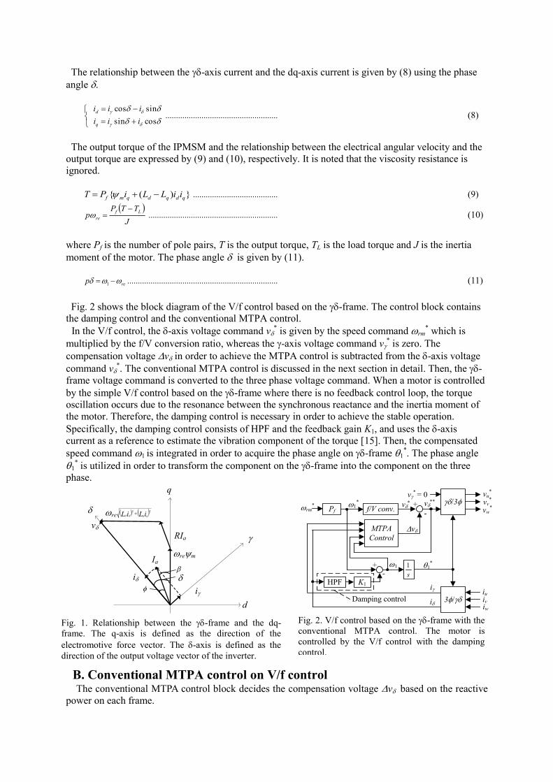
III. Proposed MTPA control with hill climbing method on V/f control Fig. 4 shows the proposed control method block diagram. In the proposed method, the MTPA
control is achieved by the hill climbing method which calculates the compensation voltage
vdepending on the output current Ia.
By introducing (8) into (1), the relationship between the dq-axis current and the dq-axis voltage in
the steady state is defined as (19).
ii1
v**
+
-LPFPI
Qdq*
Q
Qdq*
calc.
Eq. (16)
v
Fig. 3. Conventional MTPA control block diagram. The command value of the reactive power Qdq is
calculated from (16).

mreq
d
dre
qre
qdreq
d
v
v
RL
LR
LLRi
i
22
1 (19)
Here, because the -axis voltage v is zero in the V/f control, the dq-axis voltage is written as (20).
cos
sin
vv
vv
q
d ................................................ (20)
The relationship among the dq-axis current, the output current Ia and the power factor f is given by
(21).
f
f
cos
sin
cossin
sincos
-I
i
ia
q
d .................. (21)
From (19), (20) and (21), the output current Ia is expressed as (22).
222
1
22
1
222222sincos2cossin2cossin YZvZZvZZZI qmqmqda (22)
where the valuables Zd, Zq, Z and Y are defined as (23) to (26).
21
22
dd LRZ ........................................... (23)
21
22
qq LRZ ........................................... (24)
dq LLRZ 1
2 ........................................... (25)
qd LLRY
2
1
2
2 1
.......................................... (26)
It is noted that the angular frequency re is replaced as the rotating speed of the -frame 1 because
these values are same in the steady state. From (22), the output current is adjusted by the -axis
voltage v. Therefore, the MTPA control can be achieved by subtracting the compensation voltage
vfrom voltage command v
*.
In order to confirm the validity of equations, the simulation is conducted. Table I shows the motor
parameters of the IPMSM which are used in the simulation. The saliency ratio of the IPMSM is 2.5.
Fig. 5 shows the relationship between the output current Ia and the compensation voltage v of the
simulation result and the values acquired by (22). In the simulation, both results are completely
corresponded. In Fig. 5, the output current Ia has the minimum value Ia_min at the MTPA control point.
Fig. 6 shows the flowchart of the proposed MTPA control based on the hill climbing method.
Specifically, the hill climbing method is divided into four modes; Mode 1, Mode 2, Mode 3 and Mode
4. In Mode 1, the compensation voltage v is increased to find the minimum point of the output
current Ia_min. In Mode 2, the present value of the output current Ia_min is compared with the previous
value of the output current Ia. When the present value of the output current Ia is higher than the
threshold output current Ia_th, the compensation voltage v is increased in order to maintain the
minimum point of the output current. In Mode 3 and Mode 4, the compensation voltage v is
decreased and the similar operation in Mode 1 and Mode 2 are implemented. In order to alleviate the
fluctuation of the output torque during the MTPA control, the fluctuation amount of the output current
Ia should be less than 0.1 p.u.. Therefore, the compensation voltage vshould be decided according
to the fluctuation amount of the output current Ia.
When the output current Ia reaches the minimum point, the hill climbing method repeats Mode 1 to
Mode 4. When the variation value of the compensation voltage v remains constant after tracking the
minimum point of the output current, the current fluctuation occurs according to the torque fluctuation.
Therefore, the variation value of the compensation voltage v is decreased in Mode 4, in order that
the compensation voltage v converges to the MTPA control point. In addition, when the output
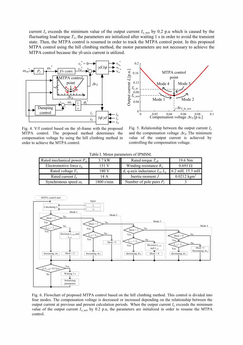
current Ia exceeds the minimum value of the output current Ia_min by 0.2 p.u which is caused by the
fluctuating load torque TL, the parameters are initialized after waiting 1 s in order to avoid the transient
state. Then, the MTPA control is resumed in order to track the MTPA control point. In this proposed
MTPA control using the hill climbing method, the motor parameters are not necessary to achieve the
MTPA control because the -axis current is utilized.
MTPA control start
Calculating Ia
Ia_n-1 > Ia_nNo
Yes
Increasing v
Decision Ia_min and
Ia_th
Mode = 1
Yes
No
Mode = 2
Mode = 2
Yes
Ia_th < Ia_n
Yes
Increasing v
No
Mode = 3
Yes
Yes
decreasing v Mode = 4
Mode = 4
Yes
Yes
decreasing v
No
No
No
No
Mode =3
No
Mode 1
Mode 2
Mode 3
Mode 4
Mode =1
Decreasing v
Input
i
i
Ia_n-1 < Ia_n
Decision Ia_min
and Ia_th
Ia_th < Ia_n
|Ia-Ia_min|>0.2 p.u.
Waiting 1 s
Initializing
parameters
Yes
No
Fig. 6. Flowchart of proposed MTPA control based on the hill climbing method. This control is divided into
four modes. The compensation voltage is decreased or increased depending on the relationship between the
output current at previous and present calculation periods. When the output current Ia exceeds the minimum
value of the output current Ia_min by 0.2 p.u, the parameters are initialized in order to resume the MTPA
control.
vu*
vv*
vw*rm
*Pf
v*
s
1
iu
iv
iw
i
i
+
-
3f/
f/v conv.
+-Damping
control
v* = 0
/3f
v
1*
1 1*
I a
MTPA control
point
v
Fig. 4. V/f control based on the -frame with the proposed
MTPA control. The proposed method determines the
compensation voltage by using the hill climbing method in
order to achieve the MTPA control.
Table I. Motor parameters of IPMSM.
Synchronous speeds
Rated mechanical power Pm 3.7 kW
Electromotive force eq 151 V
1800 r/min
Rated voltage Vn 180 V
Rated torque TeR 19.6 Nm
Winding resistance Rw .693W
d, q-axis inductance Ld, Lq 6.2 mH, 15.3 mH
Inertia moment J 0.0212 kgm2
Number of pole pairs Pf 3
14 ARated current In
0
0.04
0.08
0.12
0.16
0.2
0 0.02 0.04 0.06 0.08 0.1Compensation voltage v [p.u.]
Ou
tpu
t cu
rren
t I a
[p.u
.]
MTPA control
point
Mode 1 Mode 2
Mode 4 Mode 3
Ia_min
Ia_th
v_Ia_min
Fig. 5. Relationship between the output current Ia
and the compensation voltage v.The minimum
value of the output current is achieved by
controlling the compensation voltage.
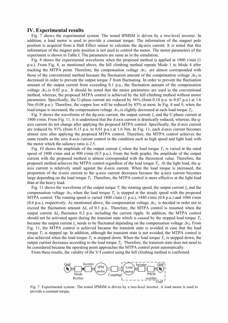
IV. Experimental results Fig. 7 shows the experimental system. The tested IPMSM is driven by a two-level inverter. In
addition, a load motor is used to provide a constant torque. The information of the magnet pole
position is acquired from a Hall Effect sensor to calculate the dq-axis current. It is noted that this
information of the magnet pole position is not used to control the motor. The motor parameters of the
experiment is shown in Table I. The parameters are same as in the simulation.
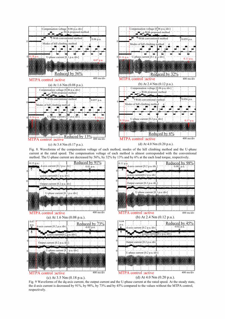
Fig. 8 shows the experimental waveforms when the proposed method is applied at 1800 r/min (1
p.u.). From Fig. 8, as mentioned above, the hill climbing method repeats Mode 1 to Mode 4 after
tracking the MTPA point. Therefore, the compensation voltage v are almost corresponded with
those of the conventional method because the fluctuation amount of the compensation voltage v is
decreased in order to prevent the output torque T from fluctuating. In order to prevent the fluctuation
amount of the output current from exceeding 0.1 p.u., the fluctuation amount of the compensation
voltage vis 0.02 p.u.. It should be noted that the motor parameters are used in the conventional
method, whereas, the proposed MTPA control is achieved by the hill climbing method without motor
parameters. Specifically, the U-phase current are reduced by 56% (from 0.18 p.u. to 0.07 p.u.) at 1.6
Nm (0.08 p.u.). Therefore, the copper loss will be reduced by 85% at most. In Fig. 8 and 9, when the
load torque is increased, the compensation voltage v is slightly decreased at each load torque TL.
Fig. 9 shows the waveforms of the dq-axis current, the output current Ia and the U-phase current at
1800 r/min. From Fig. 11, it is understood that the d-axis current is drastically reduced, whereas, the q-
axis current do not change after applying the proposed MTPA control. Specifically, the d-axis current
are reduced by 91% (from 0.15 p.u. to 0.01 p.u.) at 1.6 Nm. In Fig. 11, each d-axis current becomes
almost zero after applying the proposed MTPA control. Therefore, the MTPA control achieves the
same results as the zero d-axis current control in the condition such as high speed and light load with
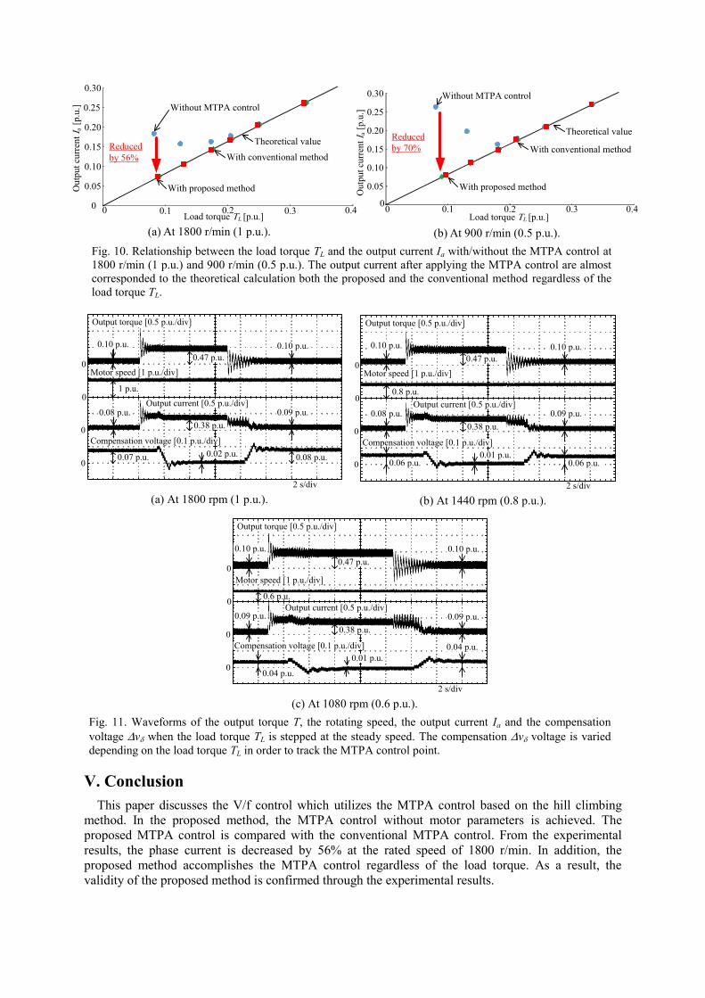
the motor which the saliency ratio is 2.5. Fig. 10 shows the amplitude of the output current Ia when the load torque TL is varied at the rated
speed of 1800 r/min and at 900 r/min (0.5 p.u.). From the both graphs, the amplitude of the output
current with the proposed method is almost corresponded with the theoretical value. Therefore, the
proposed method achieves the MTPA control regardless of the load torque TL. At the light load, the q-
axis current is relatively small against the d-axis current. When the load torque is increased, the
proportion of the d-axis current to the q-axis current decreases because the q-axis current becomes
large depending on the load torque TL. Therefore, the MTPA control is more effective at the light load
than at the heavy load.
Fig. 11 shows the waveforms of the output torque T, the rotating speed, the output current Ia and the
compensation voltage v when the load torque TL is stepped at the steady speed with the proposed
MTPA control. The rotating speed is varied 1800 r/min (1 p.u.), 1440 r/min (0.8 p.u.) and 1080 r/min
(0.6 p.u.), respectively. As mentioned above, the compensation voltage v is decided in order not to
exceed the fluctuation amount Ia of 0.1 p.u.. Therefore, the MTPA control is resumed when the
output current Ia fluctuates 0.2 p.u. including the current ripple. In addition, the MTPA control
should not be activated again during the transient state which is caused by the stepped load torque TL
because the output current Ia needs to be fluctuated depending on the compensation voltage v.From
Fig. 11, the MTPA control is achieved because the transient state is avoided in case that the load
torque TL is stepped up. In addition, although the transient state is not avoided, the MTPA control is
also achieved when the load torque TL is stepped down. When the load torque TL is stepped down, the
output current decreases according to the load torque TL. Therefore, the transient state does not need to
be considered because the operating point approaches the MTPA control point automatically.
From these results, the validity of the V/f control using the hill climbing method is confirmed.
Diode
Rctifier
Inverter InverterIPM
motorLoad
motorPWM
rectifier
Grid
Coupling
Grid
Load Fig. 7. Experimental system. The tested IPMSM is driven by a two-level inverter. A load motor is used to
provide a constant torque.
0
0
0
400 ms/div
d-axis current [0.2 p.u./div]
q-axis current[0.2 p.u./div]
U-phase current [0.1 p.u./div]
Output current [0.2 p.u./div]
0.15 p.u.
0.01 p.u.
Reduced by 91%
MTPA control :active
0
(a) At 1.6 Nm (0.08 p.u.).
0
0 U-phase current [0.1 p.u./div]
0
d-axis current [0.2 p.u./div]
q-axis current[0.2 p.u./div]
Output current [0.2 p.u./div]
0.07
p.u.-0.02 p.u.
Reduced by 73%
MTPA control :active 400 ms/div
0
(c) At 3.5 Nm (0.18 p.u.).
0
0
0
0.002 p.u.Reduced by 98%
MTPA control :active 400 ms/div
0
d-axis current [0.2 p.u./div]
q-axis current[0.2 p.u./div]
U-phase current [0.1 p.u./div]
Output current [0.2 p.u./div]
0.11 p.u.
(b) At 2.4 Nm (0.12 p.u.).
0
0
0U-phase current [0.2 p.u./div]
0
0.04
p.u.-0.02 p.u.
Reduced by 45%
MTPA control :active 400 ms/div
d-axis current [0.2 p.u./div]
q-axis current[0.2 p.u./div]
Output current [0.2 p.u./div]
(d) At 4.0 Nm (0.20 p.u.).
Fig. 9 Waveforms of the dq-axis current, the output current and the U-phase current at the rated speed. At the steady state,
the d-axis current is decreased by 91%, by 98%, by 73% and by 45% compared to the values without the MTPA control,
respectively.
0
0
0
With proposed method
With conventional method
12
3
400 ms/div
4
Compensation voltage [0.06 p.u./div]
MTPA control :active
U-phase current [0.1 p.u./div]
Modes of hill climbing method
Reduced by 56%
0.07 p.u.
0.18 p.u.
0.06 p.u.
(a) At 1.6 Nm (0.08 p.u.).
0
0
0
With proposed method
With conventional method
12
34
MTPA control :active
U-phase current [0.1 p.u./div]
Reduced by 13%
0.16 p.u. 0.14 p.u.
400 ms/div
Compensation voltage [0.06 p.u./div]
0.057 p.u.
Modes of hill climbing method
(c) At 3.4 Nm (0.17 p.u.).
0
0
0
With proposed method
With conventional method
12
34
MTPA control :active
U-phase current [0.1 p.u./div]
Reduced by 32%
0.11 p.u.
400 ms/div
0.16 p.u.
Compensation voltage [0.06 p.u./div]
0.059 p.u.
Modes of hill climbing method
(b) At 2.4 Nm (0.12 p.u.).
0
0
0
With proposed method
With conventional method
12
34
MTPA control :active
Reduced by 6%
0.18 p.u. 0.17 p.u.
400 ms/div
U-phase current [0.2 p.u./div]
Compensation voltage [0.06 p.u./div]
0.056 p.u.
Modes of hill climbing method
(d) At 4.0 Nm (0.20 p.u.).
Fig. 8. Waveforms of the compensation voltage of each method, modes of the hill climbing method and the U-phase
current at the rated speed. The compensation voltage of each method is almost corresponded with the conventional
method. The U-phase current are decreased by 56%, by 32% by 13% and by 6% at the each load torque, respectively.
V. Conclusion
This paper discusses the V/f control which utilizes the MTPA control based on the hill climbing
method. In the proposed method, the MTPA control without motor parameters is achieved. The
proposed MTPA control is compared with the conventional MTPA control. From the experimental
results, the phase current is decreased by 56% at the rated speed of 1800 r/min. In addition, the
proposed method accomplishes the MTPA control regardless of the load torque. As a result, the
validity of the proposed method is confirmed through the experimental results.
With conventional method
With proposed method
Without MTPA control
Theoretical value
Ou
tpu
t cu
rren
t I a
[p
.u.]
Load torque TL [p.u.]
0.05
0.10
0.15
0.20
0.25
0.30
0 0.1 0.2 0.3 0.40
Reduced
by 56%
(a) At 1800 r/min (1 p.u.).
Load torque TL [p.u.]
Ou
tpu
t cu
rren
t I a
[p
.u.]
With conventional method
With proposed method
Without MTPA control
Theoretical value
0.05
0.10
0.15
0.20
0.25
0.30
0 0.1 0.2 0.3 0.40
Reduced
by 70%
(b) At 900 r/min (0.5 p.u.).
Fig. 10. Relationship between the load torque TL and the output current Ia with/without the MTPA control at
1800 r/min (1 p.u.) and 900 r/min (0.5 p.u.). The output current after applying the MTPA control are almost
corresponded to the theoretical calculation both the proposed and the conventional method regardless of the
load torque TL.
Fig. 11. Waveforms of the output torque T, the rotating speed, the output current Ia and the compensation
voltage v when the load torque TL is stepped at the steady speed. The compensation v voltage is varied
depending on the load torque TL in order to track the MTPA control point.
0
0
0
2 s/div
0
Output current [0.5 p.u./div]
Output torque [0.5 p.u./div]
Compensation voltage [0.1 p.u./div]
0.08 p.u.
0.38 p.u.
0.09 p.u.
0.10 p.u.
Motor speed [1 p.u./div]
0.47 p.u.
0.10 p.u.
0.07 p.u. 0.02 p.u. 0.08 p.u.
1 p.u.
(a) At 1800 rpm (1 p.u.).
0
0
0
2 s/div
0
Output current [0.5 p.u./div]
Output torque [0.5 p.u./div]
0.08 p.u.
0.38 p.u.
0.09 p.u.
0.10 p.u.
Motor speed [1 p.u./div]
0.47 p.u.
0.10 p.u.
0.01 p.u.
0.8 p.u.
Compensation voltage [0.1 p.u./div]
0.06 p.u. 0.06 p.u.
(b) At 1440 rpm (0.8 p.u.).
0
0
0
2 s/div
0
Output current [0.5 p.u./div]
Output torque [0.5 p.u./div]
0.09 p.u.
0.38 p.u.
0.09 p.u.
0.10 p.u.
Motor speed [1 p.u./div]
0.47 p.u.
0.10 p.u.
0.01 p.u.
0.6 p.u.
Compensation voltage [0.1 p.u./div]
0.04 p.u.
0.04 p.u.
(c) At 1080 rpm (0.6 p.u.).
In future work, the relationship between the variation value of the compensation voltage vand
the hill climbing method will be clarified in order to accomplish the MTPA control in minimum
convergence time.
References [1] S. Kim, Y. Yoon, S. Sul, K. Ide: “Maximum Torque per Ampere (MTPA) Control of an IPM
Machine Based on Signal Injection Considering Inductance Saturation”, IEEE Trans. on Power
Electronics, Vol. 28, No. 1, pp. 488-497, (2013)
[2] R. Tanabe, K. Akatsu: “Advanced Torque and Current Control Techniques for PMSMs with a
Real-time Simulator Installed Behavior Motor Model”, IEEJ Journal of Industry Applications, Vol. 5,
No. 2, pp. 167-173, (2016)
[3] T. Zanma, M. Morimoto, K. Yubai: “Suppression of harmonic Current for IPMSM using
Generalized Repeatitive Control”, IEEJ Journal of Industry Applications, Vol. 3, No. 3, pp. 214-220,
(2014)
[4] J. Itoh, N. Nomura, H. Ohsawa: “A comparison between V/f control and position-sensorless vector
control for the permanent magnet synchronous motor”, in Proc. Power Conversion Conf., Vol. 3, pp.
1310-1315, (2002)
[5] M. J. Corley, R. D. Lorenz: “Rotor position and velocity estimation for a salient-pole permanent
magnet synchronous machine at standstill and high speeds”, IEEE Trans. on Industry Applications,
Vol. 34, No. 4, pp. 784-789, (1998)
[6] Z. Chen, M. Tomita, S. Doki, S. Okuma: “An extended electromotive force model for sensorless
control of interior permanent-magnet synchronous motors” IEEE Trans. on Industrial Electronics, Vol.
50, No.2, pp. 288-295, (2003)
[7] S. Morimoto, M. Sanada, Y. Takeda: “Mechanical Sensorless Drives of IPMSM With Online
Parameter Identification”, IEEE Trans. on Industry Applications, Vol. 42, No.5, (2006)
[8] M. Hasegawa, S. Yoshioka, K. Matsui: “Position Sensorless Control of Interior Permanent Magnet
Synchronous Motors Using Unknown Input Observer for High-Speed Drives”, IEEE Trans. on
Industry Applications, Vol. 45, No. 3, pp. 938-946, (2009)
[9] K. Tobari, Y. Iwaji: “Quick-Response Technique for Simplified Position Sensorless Vector
Control in Permanent Magnet Synchronous Motors”, IEEJ Journal of Industry Applications, Vol. 4,
No. 5, pp. 582-588, (2015)
[10] T. Suzuki, M. Hasegawa, M. tomita, S. Doki: “Initial Position Estimation for IPMSMs Using
Comb Filters and Effects on Various Injected Signal Frequencies”, IEEJ Journal of Industry
Applications, Vol. 4, No. 3, pp. 204-211, (2015)
[11] X. Ji, T. Noguchi: “Online q-axis Inductance Identification of IPM Synchronous Motor Based on
Relationship between Its Parameter Mismatch and Current”, IEEJ Journal of Industry Applications,
Vol. 4, No. 6, pp. 730-731, (2015)
[12] S. Bolognani, R. Petrella, A. Prearo: “Automatic Tracking of MTPA Trajectory in IPM Motor
Drives Based on AC Current Injection”, IEEE Trans. on Industry Applications, Vol. 47, No. 1, pp.105
-114, (2011)
[13] Y. Abdel-Rady, T. K. Lee: “Adaptive Self-Tuning MTPA Vector Controller for IPMSM Drive
System”, IEEE Trans. on Energy Conversation, Vol. 21, No. 3, pp. 636-644, (2006)
[14] Y. Kang, H. Jeong. K. Lee, D. Lee, J. Kim: “Simple Estimation Scheme for Initial Rotor Position
and Inductance for Effective MTPA-Operation in Wind-Power Systems using an IPMSM”, Journal of
Power Electronics, Vol. 10, No. 4, pp. 396-404, (2010)
[15] J. Itoh, Y. Nakajima, G. T. Chiang: “Maximum Torque per Ampere and Maximum Efficiency
Control Methods based on V/f control for IPM Synchronous Motor”, IEEEJ Journal of Industry
Applications, pp. 112-120, (2014)
[16] Z. Tang, X. Li, S. Dusmez, B. Akin: “A New V/f Based Sensorless MTPA Control for IPMSM
Drives”, IEEE Trans. on Power Electronics, Vol. 37, No. 2, pp. 548-558, (2015)
[17] T. M. Jahns, G. B. Kliman, T. W. Neumann: “Interior Permanent-Magnet Synchronous Motors
for Adjustable-Speed Drives”, IEEE Trans. on Industry Applications, Vol. IA-22, No.4, pp. 738-747,
(1986)