
Maximum Surface Temperature of the Thermoplastic Gear in … · filled and unreinforced polyamide...
7
ture on the flank, which can be related to the flash temperature concept developed by Blok ro for metal gears, is especially difficult to measure, and virtually no information is available in the literature concerning plastic gears. This article presents the measurements made of the temp- erature variation along the tooth profile of a plastic gear in operation. The technique is similar to that used in a previous program to measure the mean tooth surface temperature .. s For the present investigation, the plastic materials are un- filled and unreinforced polyamide 6-6 (nylon), polyoxy- methylene homopolymer (acetal) and Ultra-High-Mole- cular-Weight-Polyethylene (U H.M.WP.E.). Table 1 sum- marizes the geometry of the gears used. In all cases, the plastic gear acts as the pinion (driver) and is paired with a metal gear. The gears are run without lubrication on a four square testing rig." A parametric equation, based onalarge number of measurements, is proposed for each material in- vestigated to predict the maximum temperature in the operating conditions described .. Maximum Surface 'Temperature 0'£' the 'Thermoplastic Gear in a Non-Lubricated Plastic/Steel Gear' Pair' by Raymond Gauvin, Patrick Girard, Henri. YeDe Ec::oIePoly technique de Mont.l'eal Abstract One of the major problems of plastic gear design is the knowledge of their running temperature, Of special interest is the bulk temperature of the tooth to predict the fatigue life, and the peak temperature on the surface of the tooth to. avert surface failure .. This paper presents the results of an experimental method that uses an infrared radiometer to' measure the temperature varia- tion along the profile of a plastic geartoolh in operation. Measurements are made on 5.08, .3.17, 2.54, 2.12 mm module hob cut gears made from nylon 6-6, acetal and UHMw,PE (UItTa High Molecular Weight P,olyethylene) .. All the tests are made on a four square testing rig with thermoplastic/steel gear pairs where the plastic gear is the driver. Maximum temperature prediction curves obtained through statistical analysis of the results are presented and compared to data available from literature. Introduction It is common practice to rate thermoplastic gears by using the metal gear equation developed by Lewis' with correction factors to allow for differences in properties between metals and plastics. Although mechanical properties of plastics as a function of temperature are relatively well known," 3. ~ they are of little help, if the temperature at which the gear operates, is not known. There is some information on how to calculate the bulk- 6 and the mean tooth surface tempera- tures. 6 . 7.8 9 However, the maximum tooth surface tempera- AUTHORS: DR. RAYMOND GAUVIN is a professor of mechanical engineering at Ecole Poly technique de Montr,eai. After graduating as mechanical engineer from this institution in 1966, he obtained: his master's degree from Stanford Unioer- sityand his Ph.D. from Laval University. At Poly technique, he Ieadsareseardi team working on mechanical behavior of thermoplastics and their applications to machine elemenss. He contributed several p.apet:s in the fie.ld and served on ASTM and AGMA committees. During the last four years, he has been on leave from EcoIe Poly technique to work at the Industrial Materials Research Institute (IMRl) which is ,a new division of the NatiO'nal Research Council of Canada in MO'ntreal. There, he had the responsibility to' estabiisha research group and to initiate research wO'rk in the fie.ld of plastics processing and characterization .. He is now bade at Ecole Poly technique but remains at IMRI on a part time basis as .an invited researcher. 20 Gear Technology Analysis of Temperature Evolution. Around Gear Contour Neglecting heat flow through shafts and radiation from. surroundings, heat generated in a gear pair containing at least one plastic gear has two sources: friction and visco- elastic hysteresis. Fig. 1 represents, on a arbitrary scale, the ideal distribu- tion of friction losses on a tooth segment, A-B-C-P-D-E, of a MR. PATRICK GlR_ARD received hi's degree in mechanical engineering from fEcole Normale des Arts et Metiers de Paris in France. He then came to' Canada and received a master's degree from Ecole Poly technique de Montreal in 1979. Since then, he w.as a fulI time research associate at the same institution where he play.eda key role in the research uiori: on plastic gears. He is now a research officer at the In- dustrial Materials Research Institute in Montreat. DR. HENRI YELLE is a professor of mechanical eng.ineering at Ecole PO'lytechniqu.e de Montreal. There, he graduated as a mechanical engineer in 1967 and obtained .a master's degree from the same institution. He received his Ph.D. from the University of WaterJ'oo. He is very active on the A.GMA Plastics GeQring Committee and' contributed' seoeral papers in the field, His recent research activities also in- eludes work Dn the use of personal computer for design pur- poses.
Transcript of Maximum Surface Temperature of the Thermoplastic Gear in … · filled and unreinforced polyamide...
ture on the flank, which can be related to the flashtemperature concept developed by Blokro for metal gears, isespecially difficult to measure, and virtually no informationis available in the literature concerning plastic gears.
This article presents the measurements made of the temp-erature variation along the tooth profile of a plastic gear inoperation. The technique is similar to that used in a previousprogram to measure the mean tooth surface temperature ..sFor the present investigation, the plastic materials are un-filled and unreinforced polyamide 6-6 (nylon), polyoxy-methylene homopolymer (acetal) and Ultra-High-Mole-cular-Weight-Polyethylene (U H.M.WP.E.). Table 1 sum-marizes the geometry of the gears used. In all cases, theplastic gear acts as the pinion (driver) and is paired with ametal gear. The gears are run without lubrication on a foursquare testing rig." A parametric equation, based onalargenumber of measurements, is proposed for each material in-vestigated to predict the maximum temperature in theoperating conditions described ..
Maximum Surface 'Temperature 0'£' the'Thermoplastic Gear in a Non-Lubricated
Plastic/Steel Gear' Pair'by
Raymond Gauvin, Patrick Girard, Henri. YeDeEc::oIePoly technique de Mont.l'eal
AbstractOne of the major problems of plastic gear design is the
knowledge of their running temperature, Of special interest isthe bulk temperature of the tooth to predict the fatigue life, and thepeak temperature on the surface of the tooth to. avert surfacefailure ..This paper presents the results of an experimental methodthat uses an infrared radiometer to' measure the temperature varia-tion along the profile of a plastic geartoolh in operation.Measurements are made on 5.08, .3.17, 2.54, 2.12 mm module hobcut gears made from nylon 6-6, acetal and UHMw,PE (UItTa HighMolecular Weight P,olyethylene) .. All the tests are made on a foursquare testing rig with thermoplastic/steel gear pairs where theplastic gear is the driver. Maximum temperature prediction curvesobtained through statistical analysis of the results are presented andcompared to data available from literature.
IntroductionIt is common practice to rate thermoplastic gears by using
the metal gear equation developed by Lewis' with correctionfactors to allow for differences in properties between metalsand plastics. Although mechanical properties of plastics as afunction of temperature are relatively well known," 3. ~ theyare of little help, if the temperature at which the gearoperates, is not known. There is some information on howto calculate the bulk- 6 and the mean tooth surface tempera-tures.6. 7.8 9 However, the maximum tooth surface tempera-
AUTHORS:
DR. RAYMOND GAUVIN is a professor of mechanicalengineering at Ecole Poly technique de Montr,eai. Aftergraduating as mechanical engineer from this institution in1966, he obtained: his master's degree from Stanford Unioer-sityand his Ph.D. from Laval University. At Poly technique,he Ieadsareseardi team working on mechanical behavior ofthermoplastics and their applications to machine elemenss.He contributed several p.apet:s in the fie.ld and served onASTM and AGMA committees. During the last four years,he has been on leave from EcoIe Poly technique to work atthe Industrial Materials Research Institute (IMRl) which is ,anew division of the NatiO'nal Research Council of Canada inMO'ntreal. There, he had the responsibility to' estabiisharesearch group and to initiate research wO'rk in the fie.ld ofplastics processing and characterization .. He is now bade atEcole Poly technique but remains at IMRI on a part timebasis as .an invited researcher.
20 Gear Technology
Analysis of Temperature Evolution. Around Gear ContourNeglecting heat flow through shafts and radiation from.
surroundings, heat generated in a gear pair containing atleast one plastic gear has two sources: friction and visco-elastic hysteresis.
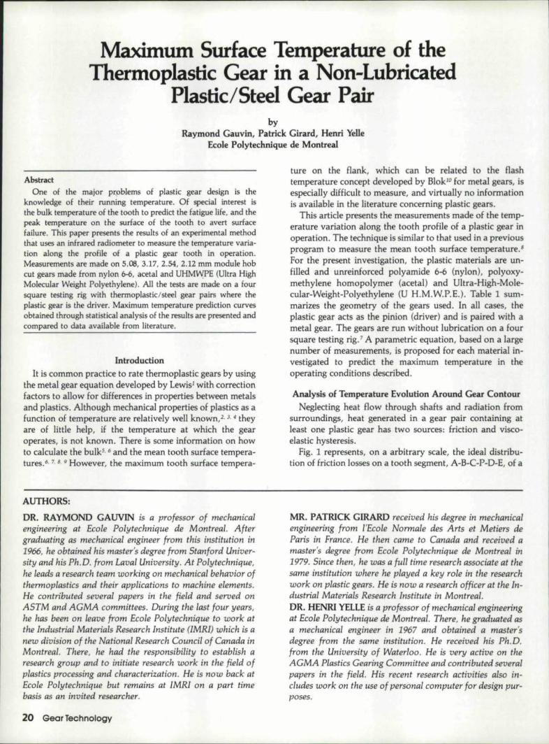
Fig. 1 represents, on a arbitrary scale, the ideal distribu-tion of friction losses on a tooth segment, A-B-C-P-D-E, of a
MR. PATRICK GlR_ARD received hi's degree in mechanicalengineering from fEcole Normale des Arts et Metiers deParis in France. He then came to' Canada and received amaster's degree from Ecole Poly technique de Montreal in1979. Since then, he w.as a fulI time research associate at thesame institution where he play.eda key role in the researchuiori: on plastic gears. He is now a research officer at the In-dustrial Materials Research Institute in Montreat.DR. HENRI YELLE is a professor of mechanical eng.ineeringat Ecole PO'lytechniqu.e de Montreal. There, he graduated asa mechanical engineer in 1967 and obtained .a master'sdegree from the same institution. He received his Ph.D.from the University of WaterJ'oo. He is very active on theA.GMA Plastics GeQring Committee and' contributed' seoeralpapers in the field, His recent research activities also in-eludes work Dn the use of personal computer for design pur-poses.
typical 24 tooth nylon gear in mesh w:ith a steel gear. Thecalculatiom, are done using the load sharing technique, II
The conditions are pitch line velocity V ... 7.2 m/see,tangential load per unit face width Wt == 70 N/mm and nolubrication. A. representative coefficient af .frictian af I' =0'.1 is used for dry nylon an steel.!
Hysteresis losses are due to. cyclic stressing of the visco-elastic material .Assuming a linear viscoelastic material,hysteresis losses per unit volume of material are, farunidirectional stressing: 12
tan (0) w ~2 E'
(1)1+ tan.1 (o)
where tan (6) is the loss factor; 0'0 is the maximum stressamplit.ude; E' is the storage modulus ande the loading fre-quency.
Hysteresis losses in a volume of material to a d pth ofPb/8 below the tooth surface (Po is the base pitch) are alsoshown on the same scale in Fig. 1. Both types of stressing arerepresented in that figure, i.e. contact compression andbending. A value af tan (6) = 0.17 is used for nylon at 50pe.rcent relative humidity and 37~.
Fig. 1 indicates that. Itheoretically, most of the heatgenerated in a plastic/steel gear pair comes from. frictian andcontart compression hysteresis an the loaded flank. Bendinghysteresis losses. shown on the nan loaded profile, appear tobe almost negligible. Since little heat is generated en the nonleaded profile (region A to B in Fig.. 1) and knowing thatplastics are poor heat conductors, the temperature in thisregion af the taoth is expected to be relatively low. How-ever, beyond point B, temperature may reach a peLk in thevi.cinity of point C, decrease towards the operating pitchpoint P; increase again to another peak in the region 01 thelowest point of contact D to finally reach, at iE, the samevalue as A.
In ather words, assuming friotion and hysteresis as being,the only heat sources, the temperature distribution along atoath profile may be expected to foUow the pattern pictured
.. - FRICTO< LOSSES_____ COM8lN(D IID!OI~G AN) CONiT''ICT
Ci/JIoIPRtS$lOfj' "-TSTE!!ESIS LOSSiE S---:1IDCJiIo«i ><'rSTE~SlS LOSSES
!Fig. l-.Reparti.tion ·of friction losses along gear profile.
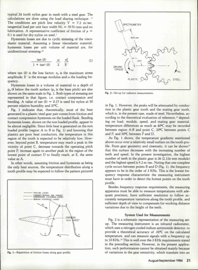
rl3. 2-Set-up fDr radianee measurements,
in Fig. 1. However, the peaks will be attenuated by conduc-tion in the plastic gear Itaoth and the mating gear tooth,which is, in the present case, made of steel .. Nevertheles , ac-cording to. the theoretieal evaluation of reference." d pend-ing on load, modul ,speed, and mating gear material,temperature differences as much as 400c may be recordedbetween region A-B and point C, 200C between paints Cand P, and 500c between P and D.
As Fig. 1 shows, the temperature gradients mentionedabove occur over 3. relatively small surface on 'the tooth pro-file. From gear geometry and cinematic, it can beshown"that this surface decreases with the increasing number ofteeth and speed. In the present investigation, the Mghestnumber of teeth m the plastic gear is 36 (2.116, mm modul )and the highest speed is 9.2 m/sec. Nating tha'! one completecycle occurs between paints Band D {Fig. 1), the frequencyappears Ito be in the order of :3 KHz. This is the lowest fre~quency response charaeterisne the measuring instrum ntmust have in order to detect the hottest points ~on the to .thprofile.
Besides frequency response r quirem nts, th measuringapparatus must be able tomeasure temperatures with ade-quate precision, have sufficient resolution Ito follew ac-curately '~emperature variations alang the taoth profile, andsufficient depth of view to compensate :for working, distancevariations due to. tn height ,of the teeth.
5ys~em, Used ~or MeasurmlentFig. 2 is a schematic representatian ,of the measuring: t-
up .. The meast:Lring instrument is an infrarredl radiometer,which uses a nitrogen cooled Indium antimonide detector, Itoprovide a Itheoreticalaccuracy of .ozoe on the calculatedtemperature, and can measure signals with a Ifrequency upIto 10 KHz.1f This is wen over the 3 KHz requirements statedin the preceding section. However, in the present applica.-tien, such performances eannot be obtained mainly becauseof variations in the gear emissivity, which translate into an
August-5ep'ember 1984 211

error on temperature, and the diameter of the measurlngspot, which rounds off temperature peaks.
The experimental error on temperature is evaluated fromthe standard deviation of emissivity measurements made onnew and worn gears ,of each material. From these measure-ments, it appears that the maximum error on temperaturelies within limits set as ±1.5"C at 20"C and ±3C at 180"C.This error includes a variation of emissivity from gear togear, which accounts for about 70 percent of the total, and asmaller error from tooth to tooth, which accounts :for therest. Therefore, for a given gear, it canbesaid that the max-imum error at 180"C is in the order of ±l "C.
The size of the measuring spot is directly related to thefield of view, which represents the solid angle that the targetsub:tends, as viewed from the apparatus, and is defined byan unvariable field aperture built into the apparatus.Theoretically, the particular apparatus used has a conicalfield of view of 2.5 milliradians, This means that the targetshould be a circle of diameter equal Ito the base of a. conehaving an apex angle of 2.5 milliradians, and a height equalto the operating distance. This corresponds to a measuringspot of 1.5 mm ata working distance of 600 mm. Also,theereucally the detector output should be directly propor-tional to all of the radiation emitted from the surface of thecircular target.
In practice, this does not appear to be exactly true; the ac-tual shape of the target, field of view, and response curve ofthe detector, as given by the manufacturer;" are presentedin Fig. 3. This figure shows that the actual field of view is anelliptical cone with minor and major axes of 3.0 and 5..0milliradians respectively. For measurements reported in thispaper, minor and major axes of the target are respectivelyaligned perpendicula:rand parallel to the axis of rotation ofthe gear.
Uthe response curve of the detector is approximated by asinusoid, and the output signal is analyzed by Fourierdecomposition, the original signal can, theoretically, be
FIELD Of VI f)N •J A)(IS
Fig. J-Shape of the measuring spot and relative response of the detector.
22 Gear Technology
reconstituted by a computer program" 'to simulate a punc-tual measuring spot. However, this method is Iimited byrandom noise present in the signal. As the measuring spotsize is further reduced by the Fourier decomposition, thenoise becomes more and more important in relation to thetemperature signal. Practical considerations limit the lowerbound o.f the simulated spot size to .approximately .5 mm ..This is a threefold increase in the original resolution of 1.Smm.
The depth view is measured as about 10 mm, which isadequate for a 5.08 mm module gear. The system usedanswers the requirements outlined in section 2.
--- MEAsuRED---- - CORRECTED
I~
ANGLE OF ROTATION, rodren
Fig. 4-Measun~d and corrected temperature signal for a used nylon. 5,06mm module gear, Wt - 38 Nzrnrn, V = 9.6 m/s.
For example, Fig., 4 presents the orginal and correctedtemperature signals obtained with a. used 5.08 mm modulenylon gear. Although the variation oEthe maximumtemperature is small, the shape of the signal. is significantlyaltered, with peaks and throughs amplified, as can be ex-pected with a smaller measuring spot. In this particular case,the correction is in the order of soc on ,the peak temperature(110°C). This is representative of 'the correction ontemperatures of this order of magnitude.
Fig. 5 shows the corrected temperature signal fora 5.08mm module UHMWPE gear. On this particular tooth, areflective aluminum foil of [ow emissivity is installed on thetop land of the tooth (C-D in Fig. 1) in order to preciselycorrelate the measured signa] with specific points on the geartooth surface. This explains the difference of the shape of thesignals between Figs. 4 and 5.
Comparison of heat generation as calculated (fig. 1) andtemperature signals, as measured I(Fig. 5) shows that themain temperature peak, which is predicted to be below thepitch circle by theoretical analysis, actually lies above thepitch circle for this, particular signal. In fact, the shap . of thetemperature signal varies widely from one material to theother. In general, it is observed that the maximumtemperature peak first appears below the pitch circle aspredicted by the theory, when the gear is new; but, as thegear wears, two peaks of different amplitude, which could

~,."lo...-------.----r-----,-------,~
LETTERS REFER TO ZONES IN FIGURE I~~
IZ' •-I-
Z'
~~Il:~WIIl:W;:»
~ow~
~ PCB E~ roL--~-O~~~--~O~~~---70~~4~-~O~.~~
ANGLE OF ROTATION. rod!!Jn
lOW EMISSIVITY DUE TOOWMINUM FOIL ON TOPL4NO OF TOOTH
Ha. 5-Corrected tl'mpefature signal with aluminised land on top of tooth,5.00 mm module UHMWPE, Wt ~ 28 Nzmm, V - 9.6 m/s,
4; 6 e 10PITCH UN[ VELOCITYI m / sec
1m :::3.18
100lJ'0 eo -
a,I--I'Ka,'EC" 20
t-'",0
I-- 2ZIWliIi,.~
100<t
I.!J::>0
'60 -al<t
W4()
(1)a:w 0a: 2=>tia::UJ 100--0..'~ 80-UIII--
'~ GO::l'::iiX<t~
•. ---'------~EX!> DATA
• 20 N/mmEQUATION (21
-40 'N/mm20 N/mm
4, 6 B
~-----.--.4 8
. ----.--.--~.I
Fig. ,6-Predicted maximum temperature rise abov ambienl (t&",." - Ta)as ,3 function 01 pitch line velocity (V) with two different loads, thrmaterials, all: B pitch (3.175 module)
10
o
vary from tooth to tooth, start to develop gradually. This isattributed to the degradation of the profiles with w ar and!,the consequent departur from Itheir exact shape with whichthe theoretical calculations are done.
Results and DiscussionSome two hundr d thirty measurements have been done
with th radiometer. These were made with several condi-tions of load and sped for each material and modules. Thplastic-metal gear pairs were first run until the operatingtemperature stabilizes. As mentioned previously, themeasurements are taken on the plastic gear (driv r) 130degrees after the cperanng pitch point. The experimentalresults are then corrected for spot diameter, and they arestatistically analyzed by computer to derive a parametric )(-pression to match th maximum surface temperatur asfunction of theop rating parameters, Of several m d Is
(Continued 01'1 p.age 26)
u..
EQUATION(2)~9'.6 mls-·-4.8mb
~ 0 ~B------~J~6-------2~4~----~32~'------40~ZWiIi.~<t JOO r------,------,-----..,..-----':7'""1U!J~. 80rn<1:'
W,(1)a:
0~ ~ ~ J_ ~
B J6 24 32 40
U. HI M. W P. E,
x~ 40-
os·!::. -------::IS=-, ------"":2:-1:.4:-,---3='2~' ------4~O
TAN(£NTI~I.. WAD/ UNIT IFACE WIDTH, ~m "3.18,
Fig. 7-Predi(ledl Maximum temperature riseabove ambient (TgrruL, - II)as a function of the tang ntial load per Wlit face width (Wt) for two dif-ferent speeds. Three materials. all: 8 pitch (3.175 module)
Augus1~ptember 1984 23

tried, the following gives the best tit:
where Ts max T. are expressed in °C and bOi b"
b2, b, areregression eoefficients calculated for each material and givenin table 2.
Using the values of regression coefficients from table 2and equation (2), curves are drawn on figs. 6,7and 8 forthe three materials studied and typical operatingparameters. Some of the experimental results, for which the'operating parameters were similar to those chosen to drawthe curves, are given for reference purposes.
ACETAL
100
~'
0'I~
II)(0e~
20
~'I-ZIJJ05,~ 100-<l!
WI
,~.<1
IIJJ(/) .,if ,20
EQUATION (2)-- 40N/mm -I-.- 20N/nvn .
fig:. B-Predicted Maximum temperature rise above ambient (Tgmax - Talas a function of the module rn for two different loads. Three materials, all4.8 m/s pitch line velocity.
26 Gecr Technology
6
(2)
As expected. the temperature increases with increasingvelocity, load and module (coarser). However, their respec-tive influence varies from one material to. another and thisreflects on values of the coefficients in table 2. While an ex-ponent smaller than 1.0 produces a convex curve, figs. 6and a, an exponent greater than one produces a concavecurve. This is illustrated by comparing curves forUHMW-PE to these for acetal or nylon in Fig. 7. The factthat UHMWPE 'behaves djffeJ1ently than the two othermaterials might be related to its peculiar properties. As amatter of fact, nylon and acetal are viscous liquids abovetheir melting points, while UHMWPE is so high inmolecular weight that it does not really melt and behavesmore like a rubber at elevated temperatures, Since the max-imum temperature generated by friction along the toothprofile can exceed the melting temperature of th material, 3
reduction in the friction coefficient for nylon and acetal canbe expected, because of the viscous liquid generated whichmoderates the rate of increase in temperature. But no suchliquid is generated for UHMWPE,and temperature risesmore and more steeply with load with a corresponding in-crease in tooth flexibility and degradation of meshingqualities.
]t must be understood that equation (2) is derived for acertain range of operating parameters which can be ob-tained from the various axis of Figs. 6 to B, They are: pitch
(Continued next page)
PROFITS ARE BEING MADE... by advertising in GIEARTECHNOLOGY, The lou rnal ofGear Manufacturing's classifiedadvertising section, Advertiseyour spedalty:
• Open time on special orunusual machines
• Unique capabillities• Machine quality.' Help wanted
.' Subcontract workYour ad reaches
over 5,0001 potential customers,can GEAR TECHNOLOGY for detail's.
(312) 437:'6604
... ~------.-------.------.~----~
,,""212 } You.. ' [91• 'm"06 _ol/Acolo'
D
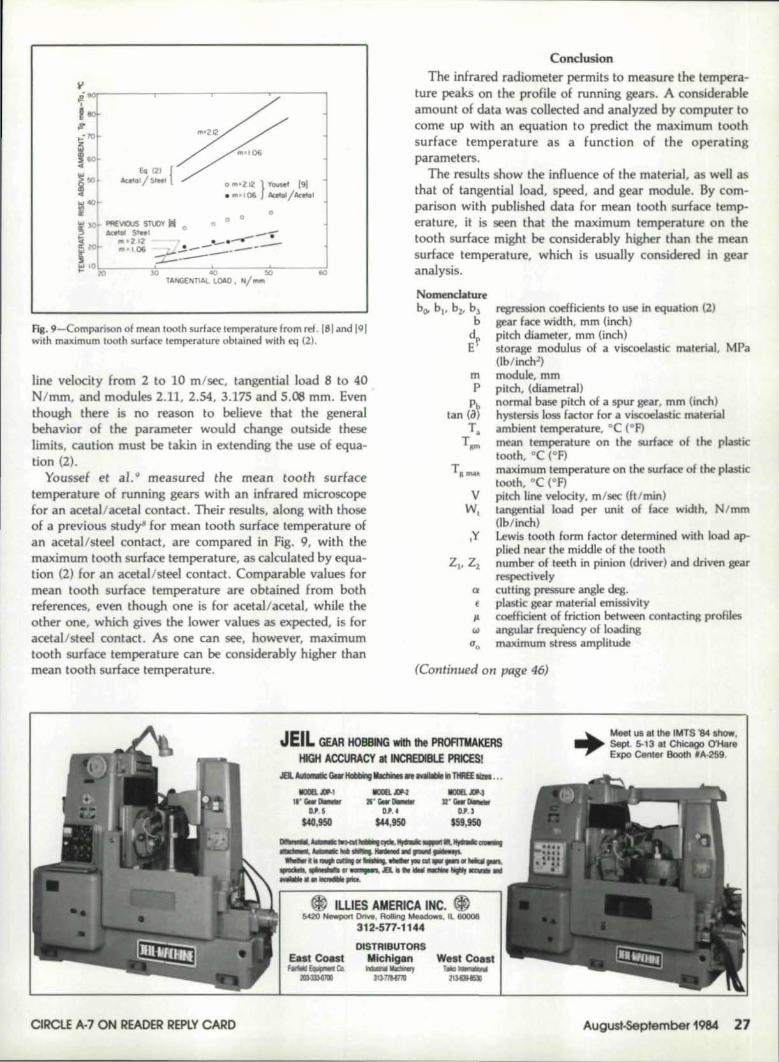
FIg. 9'-COmI'Mison of mean tooth surface temperature from ~ef. lSI and 191with maximum tooth surfac temperature obtained with eq (2).
line v@locity from. 2 to )0 m/sec, tangential load 8 to 40Nlmm, and modules 2.11. 2.54. 3.175 and 5 ..08 mm. Eventhough there is no reason to believe tha'l the generalbehavior of the parameter would ,change outside theselimits, caution must be takin in extending the use of equa-tion (2,.
Youssef et at q measured the mean tooth suriecetemperature of running gears with an infrared microscopefor an acetal/acetal, contact. Their results, along with thoseof a. previous study' for mean 'tooth surface temperature ofan acetal/steel contact, are compared in Fig. 9, with themaximum tooth surface temperature, as calculated by equa-tion {2) for an acetal/steel contact. Comp'3xable values formean tooth surface temperature are obtained fllom bothreferences. even though one is for acetal/acetal. whil.e thoth r one, which gives the lower values as expected, is foracetal/steel contact. As one can see, however, maximumtooth surface temperature can be eonsiderably higher thanmean tooth surface temperature.
'CondusianThe infrared radiemeter permits to measure the tempera-
ture peaks on the profile of running gears. A considerableamount of data was collected and analyzed by computer tocome up wilh an equation to predict 'the maximum toothsurface temperature as a function of the operatingparameters ..
The results show the influence of the material, as well asthat of tangential load, speed, and gear module. By com-parison with published data for mean tooth surface temp-erature, it is seen that Ithe maximum temperature en 'thetooth surface might be considerably higher than the meansurface temperature, which is usually considered in gearanaJ:ysis,
No:~mh,tureboo "" b2, bl
b
mp
pctan (a~
T.TID'
~on coefficients 110 use .in equation (2)gear face width. mm (inch)'pitch diameter, mm (im:h)storage modulus ofa viscoelastic material, MPaOh/inchl)
moduJ, mmpitch, (diametraI)normal base pitch of a spur gear, mm (inch)hystersis loss fad·orf,oraviscoelas:tic materialambient temperature, °C ("F)mean temperatun: en the surface of the plastictooth. DC (OF)maximum temperature on til-urEa e of th plastictooth, °C (OF)pitch line velocity, m/sec (Ft/min)tangential load per unit of faoe width, N/mm,(lblim:h)lewis tooth form factor d tcrmined with load ap-plied nearthe middle of the toothnumber of t,eethLnpinion (drivee) and driven gear~pective:ly,cutting pressuxe angle deg.plastic gear material emi.ssivity,coefficient of :friction between contacting pmfilesangular frequency of loadingmaximum stress amplitude
(Continued on page 46)
1IIDl..r:N,a'liIII'~
0,". ~1",950
IOOB.JlN'!tI:.IiIII'~
D.P. ,
IS9.9SO
,JElL GEAR IMOBBING,with the, PROA'I\tAKEmlIHIGH ACCURACY at INCREDIBlE PRICESI
'&'.AIII-- . GNr IiIIIII*Ig 1IIiI:tl1t:t .......... lilfIIREE 1izII ••.
+-Meel us a1 U1 IMIS '84 , 'how,Sep!. 5-13 at.Chlcago .o'HareE~po Center lBooth, 'A-2S9.
.1'1·'IiIII' ......
IDJ' 5MII.9S01
E& 1Coutf.tiII e-w, Co.
3DmOl!IQ
DISTRIIBUTORSMichigan
IillllNlIiIKiwwy31l·f1I.ITIIJ
West Coastt __
213<!IiQ
CIRClE A·' ON READER REPLY CARD A.ugu~,pfember 1984 27

MAXIMUM SURFACE TEMPERATURE ...(Continued from page 27)
T.o.Bl.E 1
GEAR GEOMETRY
PIMIOfi (1lIIIVER) DIII'/U GEARI'I.ASTtC(1) STIEL
.odulf. III ... S, 8• 10. 12(Pi tth. P, dl_tr.l) (5.08, 3.175,2.54,2.11'6)
Pi tct. didmeter t d 3.0 3. 4.5 {2l"'" (Inch) P (76.2) (76.2, 114.3)
H...oer of tee th IS, 24. 30. 36 15. 24. 30. 36. (5(2)ll.2
Pn'5-5ure angle \]~ dig ZO
Faer width. b 0.5 1.0.. (inch) (12.1) (25.4)
AGI'II. qu.1i ty n""or 5to 8 11
TABLE 2
VALUE OF COEFFICIENTS USED IN EQ (2)
'MATERI.AL bO b1 b2 b]
nylon 6-6 .Z354 .755 .420 .502
acetal 5.556 x 10⁻² 1.,08 .354 .225
U.H.M.':.P.E. l.98S • 10-4 L 76 .831 .687
References
1. YELLE, H., BURNS, D. J .. "Evaluation of Root BendingFatigue Strength of Til rmoplastic Gears." World Symposiumon Gears and Gear Transmissions, Dubrevnik-Kupan, PaperB-32, pp. 395-416, September 13-16, 1978.
2,. GAUVIN, R., TROTIGNON, J. P., "A New Method of Testfor Flexural Fatigue of Plastics," A.S.T.M., Journal of Testingand Evaluaticn, Vel. 6, No 1, pp.48-.51, 1978.
3. RIDDEL, M. N., KOV, G. P., OTOOLE, J. L, "Fatigue ofThermoplastics," Polymer Engineering and Science, October1966.
4. CONSTABLE, B. I., Wfl.UAMS, J. G., BURNS. D. J.,"Fatigue and Cyclic Thermal Seftening of Thermoplastics,"Journal ef Mechanical Engineering Science, Vel. 12, No. 1,pp, 20-29, 1970.
5. TSUKAMOTO, N., YANG, T., "Study on the Nylen Gearsfor Power Transmission," Werld Syrnposiurn on Gears andGear Transmissions, Dubrovnik-Kupari. Paper B-31, PI'.383-393, September 13-16, 1978.
b. HACKMAN, H., STRlCKLE, E., ''Nylon Gears," KOllstruk-Hen, Ve.l. 3, No 18,.pp. 81-94, 1966.
7. rsur, H .• POUPARD, M., 'Vltra-Hjgh-Moleculac-Weight-High-Density-Polyethylene as a Gear Material, " Polym rEngineering and Science, Vel. 15, No 2, pp. 90.96, 1975.
8. GAUVIN. R., GIRARD, P., YELLE. H., "lnvestigafionof theRunning Temperature of Plastic-Steel G~ar Pairs," ASME,Paper No. 80-e2/DET-1OB" Int. Power Trans. & Gearing Con-ference, San Francisco, August 1980.
46 Gear Technology
9. YOUSEF, 5., BURNS, D. J., MCKINl.AY, W., "Techniquesfer Assessing the Running Temperature and Fatigue Strengthof Thermoplastic Gears," Mechanism and Machine Theory,Vel. 8, PI'. 175-185, 1973.
10. BLOK, H., 'The Flash Temperature Concept," Wear, Vel. 6,PI'. 483-394, 1963 ..
11. YELLE, B., BURNS, D. J., A.G.M.A. Fall Technical Meeting,4 Seasons Hotel, Toronto, October 10-14, 1981.
12. PERSOZ. H., "Introduction a l'etude de la rheologie." Dunod,Editeur, 1960.
:1l3. YELLE, H., "Design of Thermoplastic Gears with an InvoluteTooth Profile," Ph.D.. Thesis, University of Waterloo,Ontario, 1977.
14. Instruction Manual. Spectral Master Infrared ResearchRadiometer, Model U-S50, BarnesEngineering Co., 30 Com-merce Road, Stamford, Conn., USA.
15. GIRARD, P., GAUVIN. R., "Iemperature maximale a la sur-faci! des dents des engrenages en therrnoplastique," Rapport in-terne. No EP'-,81-R-25.Ecole Poly technique de Montreal .•Juin1981.
CIRCLE E·3 ON READER REPtV CARD
This article Ulas reprinted from tile Americall Gear Manufacturers Associa-tion.
CORRECTION:ROB~RT E. SMITH's first name was listed incorrectly on
the content pag,e of 'the last issue. Mr. Smith was the authorof "Single Flank Testing of Gears:'
COMPLETE IN-HOUSEMANUFACTURING
ENGINEERINGCAPABILITY
GEAR WORKS440 N. OAKLEY BLVD .• OUCAOQ,. Il60612
Over One Million Catalog Items on Hand for Immediate ShipmentCustom-Made Parts INith Latest State-of-the-Art in CNC Equipment
DU or write for cata]~ (312) 421-6420