Maximum RF Connector Page - Freef1chf.free.fr/fichiers/datasheet relais/DowKeyCatalogue.pdf · 1...
152
Transcript of Maximum RF Connector Page - Freef1chf.free.fr/fichiers/datasheet relais/DowKeyCatalogue.pdf · 1...


DowKey Microwave Corporation 1667 Walter Street, Ventura, California 93003 (805) 650-0260 • FAX (805) 650-1734 1
Maximum RF Connector PageFrequency Type
DowKey Microwave Catalog 3DowKey Part Numbering System 4RF Power Chart 5Ordering Information 6DowKey Microwave Switch Products
401 Series Failsafe SPDT Switches 26.5 GHz SMA 8401 Series Latching SPDT Switches 26.5 GHz SMA 10402 Series Failsafe SPDT Switches 12.4 GHz N 12402 Series Latching SPDT Switches 12.4 GHz N 14403 Series Failsafe SPDT Switches 26.5 GHz SMA 16411C Series Failsafe Transfer Switches 18 GHz SMA 18411C Series Latching Transfer Switches 18 GHz SMA 20412 Series Failsafe Transfer Switches 12.4 GHz N 22412 Series Latching Transfer Switches 12.4 GHz N 24509 Series Failsafe SPDT Switches 12.4 GHz PIN 26521 Series Failsafe SPDT Terminated Switches 18 GHz SMA 28521 Series Latching SPDT Terminated Switches 18 GHz SMA 30531-561 Series Normally Open Terminated Multi-position Switches 18 GHz SMA 32531-561 Series Latching Multi-position Switches 18 GHz SMA 34531-561 Series Latching Terminated Multi-position Switches 18 GHz SMA 36531-561 Series Normally Open Multi-position Switches 12.4 GHz N 38531-561 Series Latching Multi-position Switches 12.4 GHz N 40535-565 Series Normally Open Multi-position Switches 18 GHz SMA 42571-581 Series Normally Open Multi-position Switches 18 GHz SMA 44571-581 Series Normally Open Terminated Multi-position Switches 18 GHz SMA 46571-581 Series Latching Multi-position Switches 18 GHz SMA 48571-581 Series Latching Terminated Multi-position Switches 18 GHz SMA 50591-5A1 Series Normally Open Multi-position Switches 18 GHz SMA 52591-5A1 Series Normally Open Terminated Multi-position Switches 18 GHz SMA 54591-5A1 Series Latching Multi-position Switches 18 GHz SMA 56591-5A1 Series Latching Terminated Multi-position Switches 18 GHz SMA 58433-443 Series In-line Latching Multi-position Switches 18 GHz SMA 60473-4A3 Series In-line Latching Multi-position Switches 18 GHz SMA 624C3 Series In-line Latching Multi-position Switches 18 GHz SMA 6446 Series DPDT Failsafe Switches 1000 MHz BNC, TNC 6654 Series SPDT Failsafe Switches 3000 MHz N, BNC, TNC 6860 Series SPDT Failsafe Switches 1000 MHz N, BNC, UHF 7063 Series SPDT Failsafe Switches 3 GHz N 7264 Series Transfer Failsafe Switches 3 GHz N 7466 Series SPDT Failsafe Switches 500 MHz F 7677 Series SPDT Failsafe Switches 1000 MHz BNC, F 78
Table of Contents

2DowKey Microwave Corporation 1667 Walter Street, Ventura, California 93003 (805) 650-0260 • FAX (805) 650-1734
Table of Contents
Maximum RF Connector PageFrequency Type
DowKey Microwave Switch Products (cont.)78 Series Multi-position Manual Switches 450 MHz N, BNC, UHF 8079 Series Bypass Failsafe Switches 3 GHz TNC 82116 Series SP4T Failsafe Switches 2000 MHz N, BNC, TNC 84164 Series SPDT Failsafe Switches 1000 MHz BNC, TNC 86167 Series Transfer Failsafe Switches 1000 MHz N, UHF 88169 Series SPDT Failsafe Switches 2000 MHz BNC 90260 Series DPDT 260B Series By-Pass Failsafe Switches 1000 MHz N, BNC, UHF 92310 Series SPDT High Power Vacuum Switches 400 MHz N, HN, SC 94
DowKey/Transco Microwave Switch ProductsCross Reference Guide 98909 Type DO Series SPDT Latching Switches 18 GHz SMA 100919 Type DO Series SPDT Failsafe Switches 18 GHz SMA 102905-915 Type DO Series SPDT Latching and Failsafe Switches 26.5 GHz 3.5mm 104805 Type D Series SPDT Latching Switches 12.4 GHz TNC, N 108810 Type D Series SPDT Failsafe Switches 12.4 GHz TNC, N 110900-910 Type DT Series Latching and Failsafe Switches 12.4 TNC 112800-810 Type DX Series High Power Latching and Failsafe Switches 6.5 GHz SC 114808-818 Type PD Series SPDT (MBB) Latching and Failsafe Switches 12.4 GHz TNC, N 116700 Type HO Series Transfer Latching Switches 18 GHz SMA 118710-715 Type HO & HOF Series Transfer Failsafe Switches 18 GHz SMA 120705-745 Type HO Series Transfer Latching and Failsafe Switches 26.5 GHz 3.5mm 122300 Type H Series Transfer Latching Switches 12.4 GHz N, TNC 126310 Type H Series Transfer Failsafe Switches 12.4 GHz N, TNC 128700-710 Type HT Series Transfer Latching and Failsafe Switches 12.4 GHz TNC 130300-310 Type HX Series Transfer High Power Latching and Failsafe 6.5 GHz SC 132143-146 Type MO Series Multi-position Selective Switches 18 GHz SMA 134143-146 Type MOI Series Multi-position Selective Switches 18 GHz SMA 136154-156 Type MO Series Multi-position Selective Switches 26.5 GHz 3.5mm 138133-136 Type M Series Multi-position Selective Switches 12.4 GHz N, TNC 140133-136 Type MX Series High Power Multi-position Selective Switches 6.5 GHz SC 142
DowKey/Transco Waveguide Switch ProductsCross Reference Guide 144Reference Table for Rigid Rectangular Waveguide 145Type GR Series 3 or 4 Port Latching and Failsafe Switches 4-18 GHz WR284-WR62 146Type GF Series SPDT & Transfer Latching and Failsafe Switches 8.2 GHz WRD350D24 148Type GF Series Transfer Latching and Failsafe Switches 18 GHz WRD750D24 150
DowKey Microwave Corporation 1667 Walter Street, Ventura, California 93003 (805) 650-0260 • FAX (805) 650-1734 3
DowKey Microwave Catalog
Established in 1945, DowKey became the largest producerof electro-mechanical switches when the company wasacquired in 1996 by K&L Microwave/Transco under theumbrella of Dover Technologies, division of DoverCorporation with annual revenues in excess of 4 billion dollars.
The company offers switches in the three major markets -Commercial, Military, and Hi-Rel space. DowKey Microwaveproducts are currently used in airborne, sea ground-based,military, missiles, and EW systems as well as commercialcommunication and instrumentation systems, medicalequipment, cellular telephone, two-way paging systems,PCS, PCN, test equipment, commercial airlines and satelliteapplications.
Although the product specifications listed in the catalog arefor commercial switches, Military specification and specialenvironment products are available upon request. All of theswitches are specifically designed to take the maximumadvantage of standardized parts to minimize cost and delivery.
In the last decade, DowKey’s market share has grown at arapid pace. To meet the demands of a growing company,DowKey has assembled the most experienced managementand engineering team in the industry - a team that offersinnovative approaches to designs - a team that improvesand brings new life to the product line.
These include:• Broad selection of catalog RF and Microwave
switches operating from DC to 18.5 GHz.• Custom switches operating up to 26.5 GHz.• Hi-Rel space qualified switches for military and
commercial satellites.• Complex devices using innovations that include
other components to form switch matrixes, switch attenuators, IEEE 488 compatible components,and other unique design solutions to our customer’s requirements are available.
A. DowKey Radial multithrow switches in SP3T - SP10T configurations controlled by TTL, or binary logic.
B. DowKey INTELLIGENT RELAY IN-LINE series of multithrow switches with binary logic inputs.
DowKey, located in Ventura, California - one hour north ofthe Los Angeles airport, is in the process of expanding itsfacility to 36,000 square feet. The current facility houses acertified clean room, environmental testing lab with boththermal and thermal shock capability, two 18 inch and one24 inch diameter thermal vacuum chambers, and a com-puter controlled shock and vibration system (capable of upto 100g’s).
DowKey has made a substantial commitment to quality byproviding formal training in team work and quality aware-ness to every employee of the company.
The DowKey inspection system fully complies with MIL-I-45208. Qualification testing is performed to customer spe-cific requirements including MIL-PRF-3928E. Solderers andsoldering inspectors are certified to MIL-STD-2000A. Thedocument change control system insures that productdesign, methods, and processes remain consistent withcustomer requirements. DowKey is currently pursuing ISO9001 certification.
This catalog is intended to be used as a guide in selectingthe proper type of switch or switching function for a givenapplication and to identify product families we have deliv-ered to make the system designer’s life a little easier. It isimportant to note that DowKey Microwave does not limititself to catalog products and will gladly entertain variationsto the published specifications. We welcome requestsregarding custom integrated components and switch func-tion assemblies. Drawing on DowKey Microwave’s technicalexpertise we can offer a cost effective approach for ourcustomers.

4DowKey Microwave Corporation 1667 Walter Street, Ventura, California 93003 (805) 650-0260 • FAX (805) 650-1734
DowKey Part Numbering System
X A B C - D E FG H I J
(X) RELAY FAMILY2 Low Frequency4/5 50 Ohm System7 75 Ohm System
(A) CONFIGURATION
0 SPDT A SP10T1 Transfer B SP11T2 SPST C SP12T3 SP3T D 6P7T4 SP4T5 SP5T6 SP6T7 SP7T8 SP8T9 SP9T
(B) SIZE
1 Std. Case, normally SMA connectors (Radial)2 Std. Case, normally N Connectors3 Small Case, normally SMA (Multithrow)4 Intermediate Cavity, SMA/TNC5 Miniature Radial6 Std. Case, normally N connectors (Radial)9 Microminiature Switch
(C) SPECIAL OPTIONS
A High Power K 26.5 GHzB Bypass (2-4) L Flange Mount CavityC Special Mounting M Fast Switching
Bracket N Remove STDD Bypass (1-2) Mounting BracketE Bypass (3-4) P Power ConnectorF Bypass (1-3) R Reverse PolarityG Make Before BreakH HI-REL S Seal Epoxy, Sand & DustI Seal, Immersion T -55ºC to +85ºCJ “D” Type Connector
(D) ACTUATOR COIL TYPE
1 Manual2 Failsafe, Position 13 Pulse Latching4 Latching, Self Cutoff5 Normally Open6 Failsafe, Suppression Diodes7 Pulse Latching, Suppression Diodes9 Normally Open, Suppression Diodes
(J) SPECIAL OPTIONS
A TTL HI, Commercial (2.4 - 5.5 Vdc)B TTL HI, Military (2.4 - 5.5 Vdc)C MOSFET Driver, Pulse LatchE CMOS BCD Decoding Logic &
MOSFET Driver, CommercialL TTL Logic Low, Commercial
(0.0 - 0.8 Vdc)G Other Special Circuit
(I) TERMINATIONS
1 Short 5 50Ω, 5W2 Open 6 50Ω, 10W3 50 Ω 7 50Ω, Term, Port 14 75 Ω 8 50Ω, 2W External
(H) AUXILIARY/INDICATOR CONTACTS
0 None2 Mechanical SPST3 Mechanical SPDT4 Mechanical DPDT
(FG) CONNECTORS
01 N02 BNC03 TNC04 UHF05 C07 BMA (OSP)08 SMA09 3.5mm (SMA Interface)14 TPS19 Pins (PC Board Drop-in)25 N, High Isolation (NC Port Only)26 BNC, High Isolation (NC Port Only)28 UHF, High Isolation (NC Port Only)32 F (75 Ω)44 BNC (75Ω)51 HN53 SC72 F (75Ω) High Isolation
(NC & NO Ports Only)
(E) ACTUATOR COIL VOLTAGE
0 Manual 5 110 Vdc1 6 Vdc 6 110 Vac2 12 Vdc 7 20 Vdc3 28 Vdc 8 24 Vdc4 48 Vdc 9 15 Vdc

DowKey Microwave Corporation 1667 Walter Street, Ventura, California 93003 (805) 650-0260 • FAX (805) 650-1734 5
This chart is based on the following conditions:Ambient Temperature= 40° C; Altitude= Sea Level; VSWR= 1.0:1; Non-switching
UHF connectors are not recommended for applications above 300MHz.Please consult factory for additional information.
VSWR Derating Factor VSWR Derating Factor
1.5:1 .96 3.5:1 .07
2.0:1 .88 4.0:1 .64
2.5:1 .84 4.5:1 .06
3.0:1 .75 5.0:1 .56
Power Chart

6DowKey Microwave Corporation 1667 Walter Street, Ventura, California 93003 (805) 650-0260 • FAX (805) 650-1734
Ordering Information
PACKAGING
All products shipped from the DowKey facility are packaged in accor-dance with best commercial practices unless otherwise specified in thecontract or purchase order.
SHIPPING
Shipment by commercial air freight is recommended to ensure safehandling and prompt deliver. Orders within the continuous U.S. will beshipped Via United Parcel Service unless other directions are received.
TERMS
Standard terms are net, 30 days, F.O.B. Ventura California. There is a$250 minimum order for shipments to domestic (USA) destinations.
DELIVERY
Most standard products are available from stock or within typical man-ufacturing lead time of 6-8 weeks after receipt of an order.
PRICES AND SPECIFICATIONS
Quotations for standard catalog items, in any quantity, are availablefrom the factory or the nearest factory authorized representative.Quotations are normally valid for a period of sixty days. Special itempricing is available after definition of customer requirements and con-sultation with DowKey Microwave Corporation engineering, manufactur-ing and sales.
APPLICATIONS/TECHNICAL ASSISTANCE
Approximately one-half of DowKey Microwave Corporation’s prod-ucts are items built to customer specifications. These items havebeen designed and manufactured to satisfy unique requirements.DowKey provides a knowledgeable and experienced engineeringstaff to work closely with customers in systems design and appli-cations development. This service is available for either the com-plete design of specialized switching components or switchingfunction subsystems, or in minor modification to existing standardproducts to meet a customer’s specific requirements. DowKeyapplications engineers will work co-operatively with customerengineering staff to fulfill special requirements.
WARRANTY
DowKey Microwave Corporation warrants all switch products to befree of defects in material or workmanship for a period of one yearafter the date of initial shipment. The limit of liability under thiswarranty is to repair or replace any product or part thereof which isreturned by the purchaser, and proves defective after examinationby DowKey. This warranty does not extend to any products mis-handled, misused, or subjected to abuse or neglect in storage,transportation , or use. Please call DowKey’s RMA department toreceive a return authorization number prior to returning any itemunder this warranty. Items being returned from locations outsideof the U.S. should be sent Via Air Parcel Post unless other meansare specifically agreed upon by DowKey Microwave Corporation.Repairs or alterations made without consent or knowledge ofDowKey Microwave Corporation will invalidate this warranty. Thiswarranty supercedes all others, either expressed or implied.
DowKey MICROWAVE CORPORATION continually improves prod-ucts as new technologies and components become available. We,therefore, reserve the right to alter, amend, discontinue or replaceany product and or specifications at our sole discretion in this cata-log without prior notice.

7DowKey Microwave Corporation 1667 Walter Street, Ventura, California 93003 (805) 650-0260 • FAX (805) 650-1734
DowKey®
Microwave Switches
DowKey

401 Series Failsafe
The DowKey Microwave 401 Series SPDT switches perform broadbandhigh performance switching functions extending to 26.5 GHz on selectedunits.The 401 Series switching mechanism has a break-before-make configu-ration, with a balanced actuator which provides excellent tolerance toshock and vibration.
The 401 Series switch utilizes DowKey designed connectors featuring amechanically captivated center contact which eliminates epoxy staking,and reduces RF leakage. Due to the small size of these switches, onlySMA connectors are available.
Typical applications for the 401 Series include:• Test Equipment Band Selection• Switch Matrixes• EW and Missile Systems• Microwave Radio
NominalCoil Connector Standard with Mechanical
Voltage Type Indicators
12 Vdc SMA 401-2208 401-22083228 Vdc SMA 401-2308 401-230832
TTL Compatible Logic12 Vdc SMA 401-220802A 401-220832A28 Vdc SMA 401-230802A 401-230832A
Connectors and Part Numbers
Operating Voltage:(across temperature range)
12 Vdc (11-14 Vdc)28 Vdc (24-32 Vdc)
Coil Current (Nominal):12 Vdc 185 mA28 Vdc 90 mA
Switching Time:15 mS maximum
Operating Temperature:-25ºC to +65ºC
Mechanical Life, Cycles:1 x 10⁶ minimum
Vibration, Operating:10G RMS, 20-2000 Hz
Mechanical Shock, Non-Operating:50G, 1/2 Sine, 11mS
Nominal Weight:2.5 oz., (71g.)
Specifications :
DowKey® 401 SeriesFailsafe
8DowKey Microwave Corporation 1667 Walter Street, Ventura, California 93003 (805) 650-0260 • FAX (805) 650-1734
Frequency VSWR Isolation Ins. Loss RF PowerGHz (max) dB (min) dB (max) Watts (CW)
0-1 1.10 85 0.10 1001-4 1.20 80 0.20 504-8 1.30 70 0.30 358-12 1.40 65 0.40 25
12-18 1.50 60 0.50 10*18-26.5 1.50 60 0.60 10
* “K” option only. Ex: 401K-2208
RF Characteristics

Mechanical
Electrical
401 Series
9
Available Options
DowKey Microwave Corporation 1667 Walter Street, Ventura, California 93003 (805) 650-0260 • FAX (805) 650-1734
Immersion Seal
9 PIN “D” Plug
5ms Switching Time
Increased Power Handling
Operating Voltages:15, 20, 24 Vdc
Jan TX TTL Drive Components
-55°C to +85°C Operation
DC - 26.5 GHz Operation

RF Characteristics
401 Series Latching
The DowKey Microwave 401 Series SPDT switches perform broadbandhigh performance switching functions extending to 26.5 GHz.The 401 Series switching mechanism has a break-before-make config-uration, with a balanced actuator which provides excellent tolerance toshock and vibration.
Due to the small size of these switches, only the SMA connectors areavailable. These DowKey designed connectors feature a mechanicallycaptivated center contact which eliminates epoxy staking, and reducesRF leakage. All self cutoff models include coil suppression diodes.
Typical applications for the 401 Series include:• Test Equipment Band Selection• Switch Matrixes• EW and Missile Systems• Microwave Radio
Nominal Coil Connector Standard with MechanicalVoltage Type SPDT Indicators
Pulse Latch12 Vdc SMA 401-3208 401-32083228 Vdc SMA 401-3308 401-330832
Latching with Self Cut-off12 Vdc SMA 401-4208 401-42083228 Vdc SMA 401-4308 401-430832
Latching with Self Cut-Off, TTL Compatible12 Vdc SMA 401-420802A 401-420832A28 Vdc SMA 401-430802A 401-430832A
Connectors and Part Numbers
Operating Voltage:(across temperature range)
12 Vdc (11-14 Vdc)28 Vdc (24-32 Vdc)
Coil Current (Nominal):12 Vdc 218 mA28 Vdc 108 mA
Switching Time:15 mS maximum
Operating Temperature:-25ºC to +65ºC
Mechanical Life, Cycles:1 x 10⁶ minimum
Vibration, Operating:10G RMS, 20-2000 Hz
Mechanical Shock, Non-Operating:50G, 1/2 Sine, 11mS
Nominal Weight:2.5 oz., (71g.)
Specifications :
DowKey® 401 SeriesLatching
10DowKey Microwave Corporation 1667 Walter Street, Ventura, California 93003 (805) 650-0260 • FAX (805) 650-1734
Frequency VSWR Isolation Ins. Loss RF PowerGHz (max) dB (min) dB (max) Watts (CW)
0-1 1.10 85 0.10 1001-4 1.20 80 0.20 504-8 1.30 70 0.30 35
8-12 1.40 65 0.40 2512-18 1.50 60 0.60 10
*18-26.5 1.50 60 0.60 10* “K” option only. Ex: 401K-3208

Available Options
Mechanical
Electrical
401 Series
11DowKey Microwave Corporation 1667 Walter Street, Ventura, California 93003 (805) 650-0260 • FAX (805) 650-1734
Immersion Seal
9 PIN “D” Plug
5ms Switching Time
Increased Power Handling
Operating Voltages:15, 20, 24 Vdc
-55°C to +85°C Operation
DC - 26.5 GHz Operation
Available Options

402 Series Failsafe
The DowKey Microwave 402 Series switches are designed for high per-formance in microwave systems to 12.4 GHz. They are commonly usedfor any application where high isolation and low VSWR are required. TheDowKey designed type ”N” connector features a mechanically captivat-ed center conductor which eliminates epoxy staking, and consequently,RF leakage. The balanced actuator is designed for uniform contactpressure in either switch position, which provides low and stable contact resistance over the life of the switch.
Typical applications for the 402 Series include:• Main/Standby Switching of Transponders, Transmitters, Antennas• Band Selection• Polarization Switching
Nominal Coil Connector Standard with MechanicalVoltage Type Indicators
12 Vdc N 402-2201 402-22013228 Vdc N 402-2301 402-230132
TTL Compatible Logic12 Vdc N 402-220102A 402-220132A28 Vdc N 402-230102A 402-230132A
Connectors and Part Numbers
Operating Voltage:(across temperature range)
12 Vdc (11-14 Vdc)28 Vdc (24-32 Vdc)
Coil Current (Nominal):12 Vdc 261 mA28 Vdc 108 mA
Switching Time:20 mS maximum
Operating Temperature:-25ºC to +65ºC
Mechanical Life, Cycles:1 x 10⁶ minimum
Vibration, Operating:10G RMS, 20-2000 Hz
Mechanical Shock, Non-Operating:50G, 1/2 Sine, 11mS
Nominal Weight:9.0 oz., (260g.)
Specifications :
DowKey® 402 SeriesFailsafe
RF Characteristics
DowKey Microwave Corporation 1667 Walter Street, Ventura, California 93003 (805) 650-0260 • FAX (805) 650-1734
Frequency VSWR Isolation Ins. Loss RF PowerGHz (max) dB (min) dB (max) Watts (CW)
0-1 1.15 85 0.15 3501-2 1.20 80 0.20 2502-4 1.25 70 0.25 1504-8 1.35 65 0.35 120
8-12.4 1.50 60 0.50 100
12
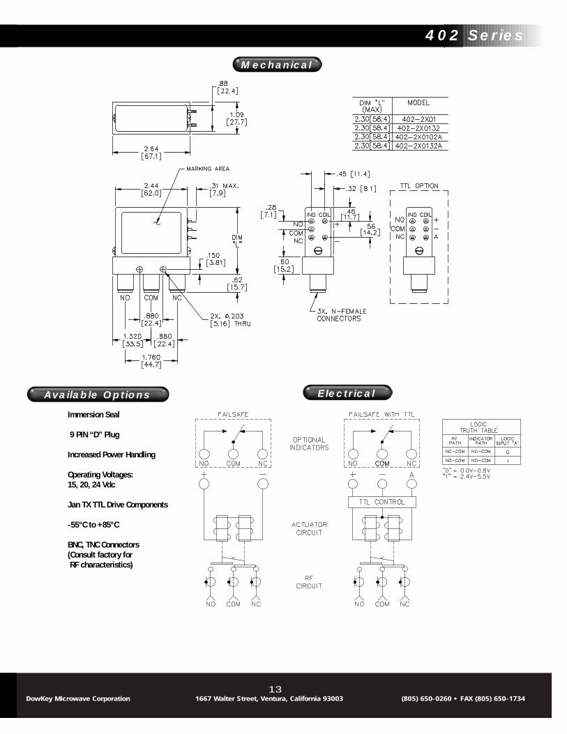
Available Options
Mechanical
Electrical
402 Series
13
Available Options
DowKey Microwave Corporation 1667 Walter Street, Ventura, California 93003 (805) 650-0260 • FAX (805) 650-1734
Immersion Seal
9 PIN “D” Plug
Increased Power Handling
Operating Voltages:15, 20, 24 Vdc
Jan TX TTL Drive Components
-55°C to +85°C
BNC, TNC Connectors(Consult factory for RF characteristics)

RF Characteristics
402 Series Latching
The DowKey Microwave 402 Series switches are designed for high per-formance in microwave systems to 12.4 GHz. They are commonly usedfor any application where high isolation and low VSWR are required. TheDowKey designed type “N” connector features a mechanically captivat-ed center conductor which eliminates epoxy staking, and consequently,RF leakage. The balanced actuator is designed for uniform contactpressure in either switch position, which provides low and stable con-tact resistance over the life of the switch. A set of auxiliary contacts isoptionally available.
Typical applications for the 402 Series include:• Main/Standby Switching of Transponders, Transmitters, Antennas• Band Selection• Polarization Switching
Nominal Coil Connector Standard with MechanicalVoltage Type Indicators
Pulse Latch12 Vdc N 402-3201 402-32013228 Vdc N 402-3301 402-330132
Latching with Self Cut-Off12 Vdc N 402-4201 402-42013228 Vdc N 402-4301 402-430132
Latching with Self Cut-Off, TTL Compatible12 Vdc N 402-420102A 402-420132A28 Vdc N 402-430102A 402-430132A
Connectors and Part Numbers
Operating Voltage:(across temperature range)
12 Vdc (11-14 Vdc)28 Vdc (24-32 Vdc)
Coil Current (Nominal):12 Vdc 300 mA28 Vdc 127 mA
Switching Time:20 mS maximum
Operating Temperature:-25ºC to +65ºC
Mechanical Life, Cycles:1 x 10⁶ minimum
Vibration, Operating:10G RMS, 20-2000 Hz
Mechanical Shock, Non-Operating:50 G, 1/2 Sine, 11 mS
Nominal Weight:9.0 oz. (260g.)
Specifications :
DowKey® 402 SeriesLatching
Frequency VSWR Isolation Ins. Loss RF PowerGHz (max) dB (min) dB (max) Watts (CW)
0-1 1.15 85 0.15 3501-2 1.20 80 0.20 2502-4 1.25 70 0.25 1504-8 1.35 65 0.35 120
8-12.4 1.50 60 0.50 100
14DowKey Microwave Corporation 1667 Walter Street, Ventura, California 93003 (805) 650-0260 • FAX (805) 650-1734

Available Options
15
Immersion Seal
9 PIN “D” Plug
Increased Power Handling
Operating Voltages:15, 20, 24 Vdc
-55°C to +85°C
BNC, TNC Connectors(Consult factory for RF characteristics)
Available Options
DowKey Microwave Corporation 1667 Walter Street, Ventura, California 93003 (805) 650-0260 • FAX (805) 650-1734
402 Series
Mechanical
Electrical

RF Characteristics
403 Series Failsafe
The DowKey Microwave 403 Series SPDT switches perform broadbandand high frequency, switching with extended performance to 26.5 GHz.The 403 Series switching mechanism uses the same break-before-make balanced actuator as the 401 Series failsafe switches. This actu-ator provides excellent tolerance to shock and vibration.
Due to the small size of these switches, only SMA connectors areavailable. These DowKey designed connectors feature a mechanicallycaptivated center contact which eliminates epoxy staking, and reducesRF leakage.
Typical applications for the 403 Series include:• Test Equipment Band Selection• Switch Matrixes• EW and Missile Systems• Microwave Radio
Nominal Coil Connector StandardVoltage Type
12 Vdc SMA 403-220828 Vdc SMA 403-2308
TTL Compatible Logic12 Vdc SMA 403-220802A28 Vdc SMA 403-230802A
Connectors and Part Numbers
Operating Voltage:(across temperature range)
12 Vdc (11-14 Vdc)28 Vdc (24-32 Vdc)
Coil Current (Nominal):12 Vdc 185 mA28 Vdc 90 mA
Switching Time:15 mS maximum
Operating Temperature:-25ºC to +65ºC
Mechanical Life, Cycles:1 x 10⁶ minimum
Vibration, Operating:10 G RMS, 20-2000 Hz
Mechanical Shock, Non-Operating:50 G, 1/2 Sine, 11 mS
Nominal Weight:1.5 oz., (42g.)
Specifications :
DowKey® 403 SeriesFailsafe
Frequency VSWR Isolation Ins. Loss RF PowerGHz (max) dB (min) dB (max) Watts (CW)
0-1 1.10 85 0.10 1001-4 1.20 80 0.20 504-8 1.30 70 0.30 358-12 1.40 65 0.40 25
12-18 1.50 60 0.50 10*18-26.5 1.50 60 0.50 10
16DowKey Microwave Corporation 1667 Walter Street, Ventura, California 93003 (805) 650-0260 • FAX (805) 650-1734
* “K” option only. Ex: 403K-2208

Available Options
17
Immersion Seal
Increased Power Handling
Operating Voltages:15, 20, 24 Vdc
-55°C to +85°C Operation
DC - 26.5 GHz Operation
Available Options
DowKey Microwave Corporation 1667 Walter Street, Ventura, California 93003 (805) 650-0260 • FAX (805) 650-1734
403 Series
Mechanical
Electrical

411C Series Failsafe
The DowKey Microwave 411 Series is a failsafe transfer switch foruse in applications where high isolation, low VSWR, and low insertionloss are critical. The DowKey designed connector features a mechani-cally captivated center conductor which eliminates epoxy staking, andconsequently, RF leakage. The 411 Series features the same reliablebalanced actuator designs as are found in the 401 Series.
Typical applications for the 411 Series include:• Switch Matrixes• Standby Transmitters with Dummy Load• Alternate Antenna Select
Frequency VSWR Isolation Ins. Loss RF PowerGHz (max) dB (min) dB (max) Watts (CW)
0-1 1.10 85 0.10 2001-4 1.20 80 0.20 1004-8 1.30 70 0.30 508-12 1.40 65 0.40 35
12-18 1.50 60 0.50 25
RF Characteristics
Nominal Coil Connector Standard with MechanicalVoltage Type Indicators
12 Vdc SMA 411C-2208 411C-22083228 Vdc SMA 411C-2308 411C-230832
TTL Compatible Logic12 Vdc SMA 411C-220802A 411C-220832A28 Vdc SMA 411C-230802A 411C-230832A
Connectors and Part Numbers
Operating Voltage:(across temperature range)
12 Vdc (11-14 Vdc)28 Vdc (24-32 Vdc)
Coil Current (Nominal):12 Vdc 364 mA28 Vdc 138 mA
Switching Time:20 mS maximum
Operating Temperature:-25ºC to +65ºC
Mechanical Life, Cycles:1 x 10⁶ minimum
Vibration, Operating:10G RMS, 20-2000 Hz
Mechanical Shock, Non-Operating:50 G, 1/2 Sine, 11 mS
Nominal Weight:4.0 oz., (115g.)
Specifications :
DowKey® 411C SeriesFailsafe
18DowKey Microwave Corporation 1667 Walter Street, Ventura, California 93003 (805) 650-0260 • FAX (805) 650-1734

Available Options
19
BYPASS (2-4)
BYPASS (1-3)
BYPASS (1-2)
BYPASS (3-4)
9 PIN “D” Plug
Operating Voltages:15, 20, 24 Vdc
Jan TX TTL Drive Components
-55°C to +85°C
DowKey Bracket
Available Options
DowKey Microwave Corporation 1667 Walter Street, Ventura, California 93003 (805) 650-0260 • FAX (805) 650-1734
411C Series
Mechanical
Electrical

411C Series Latching
The DowKey Microwave 411 Series is a latching transfer switch for use inapplications where high isolation, low VSWR, and low insertion loss are criti-cal. The DowKey designed connector features a mechanically captivatedcenter conductor which eliminates epoxy staking, and consequently, RFleakage. The 411 Series is available with pulse latching, and latching withself-cutoff actuators. Standard 411 Series latching switches are providedwith four DC control terminals which allow the user to wire either a positive(+) or negative (-) common control line. On request, DowKey can provide athree terminal configuration with the common control line internally wired.All logic controlled models include an electronic self-cutoff circuit with sup-pression diodes.
Typical applications for the 411 Series include:• Switch Matrixes• Standby Transmitters with Dummy Load• Alternate Antenna Select
Frequency VSWR Isolation Ins. Loss RF PowerGHz (max) dB (min) dB (max) Watts (CW)
0-1 1.10 85 0.10 2001-4 1.20 80 0.20 1004-8 1.30 70 0.30 50
8-12 1.40 65 0.40 3512-18 1.50 60 0.50 25
RF Characteristics
Nominal Coil Connector Standard with MechanicalVoltage Type Indicators
Pulse Latching12 Vdc SMA 411C-3208 411C-32083228 Vdc SMA 411C-3308 411C-330832
Latching with Self Cut-Off12 Vdc SMA 411C-4208 411C-42083228 Vdc SMA 411C-4308 411C-430832
Latching with Self Cut-Off, TTL Compatible12 Vdc SMA 411C-420802A 411C-420832A28 Vdc SMA 411C-430802A 411C-430832A
Connectors and Part Numbers
Operating Voltage:(across temperature range)
12 Vdc (11-14 Vdc)28 Vdc (24-32 Vdc)
Coil Current (Nominal):12 Vdc 300 mA28 Vdc 127 mA
Switching Time:20 mS maximum
Operating Temperature:-25ºC to +65ºC
Mechanical Life, Cycles:1 x 10⁶ minimum
Vibration, Operating:10 G RMS, 20-2000 Hz
Mechanical Shock, Non-Operating:50 G, 1/2 Sine, 11 mS
Nominal Weight:4.0 oz., (115g.)
Specifications :
DowKey® 411C SeriesLatching
20DowKey Microwave Corporation 1667 Walter Street, Ventura, California 93003 (805) 650-0260 • FAX (805) 650-1734

Available Options
21
Available Options
DowKey Microwave Corporation 1667 Walter Street, Ventura, California 93003 (805) 650-0260 • FAX (805) 650-1734
411C Series
Mechanical
Electrical
BYPASS (2-4)
BYPASS (1-3)
BYPASS (1-2)
BYPASS (3-4)
Reverse Polarity
9 PIN “D” Plug
Operating Voltages:15, 20, 24 Vdc
Jan TX TTL Drive Components
-55°C to +85°C
DowKey Bracket

412 Series Failsafe
The DowKey Microwave 412 Series switches are designed for high per-formance, high power applications in microwave systems to 12.4 GHz.The RF path is optimized for Type “N” connectors. The DowKeydesigned connector features a mechanically captivated center conduc-tor. This eliminates epoxy staking, and consequently, RF leakage. Alllogic controlled models include an electronic self-cutoff circuit.
Typical applications for the 412 Series include:• Switch Matrixes• Standby Transmitters with Dummy Load• Alternate Antenna Select
Frequency VSWR Isolation Ins. Loss RF PowerGHz (max) dB (min) dB (max) Watts (CW)
0-1 1.15 85 0.15 10001-2 1.20 80 0.20 3502-4 1.25 70 0.25 2504-8 1.35 65 0.35 150
8-12.4 1.50 60 0.50 120
RF Characteristics
Nominal Coil Connector Standard with MechanicalVoltage Type Indicators
12 Vdc N 412-2201 412-22013228 Vdc N 412-2301 412-230132
TTL Compatible Logic12 Vdc N 412-220102A 412-220132A28 Vdc N 412-230102A 412-230132A
Connectors and Part Numbers
Operating Voltage:(across temperature range)
12 Vdc (11-14 Vdc)28 Vdc (24-32 Vdc)
Coil Current (Nominal):12 Vdc 300 mA28 Vdc 175 mA
Switching Time:20 mS maximum
Operating Temperature:-25ºC to +65ºC
Mechanical Life, Cycles:1 x 10⁶ minimum
Vibration, Operating:10 G RMS, 20-2000 Hz
Mechanical Shock, Non-Operating:30 G, 1/2 Sine, 11 mS
Nominal Weight:14 oz., (397g.)
Specifications :
DowKey® 412 SeriesFailsafe
22DowKey Microwave Corporation 1667 Walter Street, Ventura, California 93003 (805) 650-0260 • FAX (805) 650-1734

Available Options
23
Immersion Seal
Operating Voltages:15, 20, 24 Vdc
Jan TX TTL Drive Components
-55°C to +85°C Operation
BNC, TNC Connectors(Consult factory forRF characteristics)
DowKey Bracket
Available Options
DowKey Microwave Corporation 1667 Walter Street, Ventura, California 93003 (805) 650-0260 • FAX (805) 650-1734
412 Series
Mechanical
Electrical
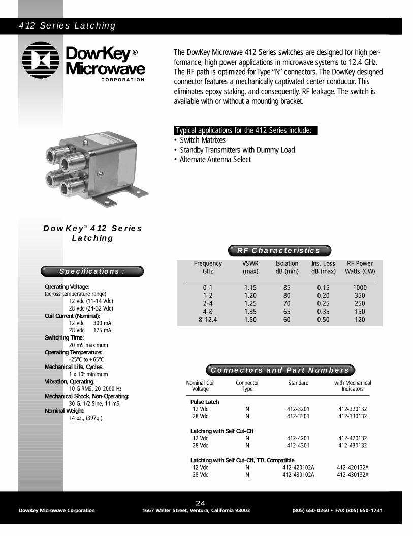
412 Series Latching
The DowKey Microwave 412 Series switches are designed for high per-formance, high power applications in microwave systems to 12.4 GHz.The RF path is optimized for Type “N” connectors. The DowKey designedconnector features a mechanically captivated center conductor. Thiseliminates epoxy staking, and consequently, RF leakage. The switch isavailable with or without a mounting bracket.
Typical applications for the 412 Series include:• Switch Matrixes• Standby Transmitters with Dummy Load• Alternate Antenna Select
RF Characteristics
Nominal Coil Connector Standard with MechanicalVoltage Type Indicators
Pulse Latch12 Vdc N 412-3201 412-32013228 Vdc N 412-3301 412-330132
Latching with Self Cut-Off12 Vdc N 412-4201 412-42013228 Vdc N 412-4301 412-430132
Latching with Self Cut-Off, TTL Compatible12 Vdc N 412-420102A 412-420132A28 Vdc N 412-430102A 412-430132A
Connectors and Part Numbers
Operating Voltage:(across temperature range)
12 Vdc (11-14 Vdc)28 Vdc (24-32 Vdc)
Coil Current (Nominal):12 Vdc 300 mA28 Vdc 175 mA
Switching Time:20 mS maximum
Operating Temperature:-25ºC to +65ºC
Mechanical Life, Cycles:1 x 10⁶ minimum
Vibration, Operating:10 G RMS, 20-2000 Hz
Mechanical Shock, Non-Operating:30 G, 1/2 Sine, 11 mS
Nominal Weight:14 oz., (397g.)
Specifications :
DowKey® 412 SeriesLatching
24DowKey Microwave Corporation 1667 Walter Street, Ventura, California 93003 (805) 650-0260 • FAX (805) 650-1734
Frequency VSWR Isolation Ins. Loss RF PowerGHz (max) dB (min) dB (max) Watts (CW)
0-1 1.15 85 0.15 10001-2 1.20 80 0.20 3502-4 1.25 70 0.25 2504-8 1.35 65 0.35 150
8-12.4 1.50 60 0.50 120

Available Options
25
Immersion Seal
Operating Voltages:15, 20, 24 Vdc
Jan TX TTL Drive Components
-55°C to +85°C Operation
BNC, TNC Connectors(Consult factory forRF characteristics)
DowKey Bracket
Available Options
DowKey Microwave Corporation 1667 Walter Street, Ventura, California 93003 (805) 650-0260 • FAX (805) 650-1734
412 Series
Mechanical
Electrical

509 Series Failsafe
The DowKey Microwave 509 Series SP2T Failsafe switch is a micro-miniature, PC board mount SPDT coaxial switch. The switch wasdesigned specifically for applications where small size, reduced weight,and less power consumption are required. Overall size is only0.75”x0.75”x0.25” and the weight is 0.5 ounce. The actuator con-sumes less than one watt which is 30% less power than similardesigns.
The RF characteristics are excellent over the DC-12.4 GHz frequencyrange. Because the 509 is hermetically laser sealed after being vacuumbaked and backfilled with an inert gas, it is able to satisfy hot switchingrequirements. The 509 has been subjected to 50 Watts (CW) hotswitching at 1GHZ and had minimal RF degradation after one millioncycles.
Typical applications for the 509 Series include:• Microwave Radio• EW and Missile Systems• Repeater Stations
Frequency VSWR Isolation Ins. Loss RF PowerGHz (max) dB (min) dB (max) Watts (CW)
DC-1 1.25 60 0.35 501-8 1.30 50 0.40 30
8-12.4 1.45 50 0.45 10
RF Characteristics
Nominal Coil Connector StandardVoltage Type
12 Vdc PIN 509-221928 Vdc PIN 509-2319
Connectors and Part Numbers
Operating Voltage:(across temperature range)
12 Vdc (11-14 Vdc)28 Vdc (24-32 Vdc)
Coil Current (Nominal):12 Vdc 83 mA28 Vdc 37 mA
Switching Time:15 mS maximum
Operating Temperature:-25ºC to +65ºC
Mechanical Life, Cycles:1 x 10⁶ minimum
Vibration:10 G RMS, 20-2000 Hz
Mechanical Shock:30 G, 1/2 Sine, 11 mS
Nominal Weight:0.5 oz., (14.2g.)
Specifications :
DowKey® 509 SeriesFailsafe
26DowKey Microwave Corporation 1667 Walter Street, Ventura, California 93003 (805) 650-0260 • FAX (805) 650-1734

Available Options
Mechanical
Electrical
27
Operating Voltages:15, 20, 24 Vdc
-55°C to +85°C Operation
Available Options
DowKey Microwave Corporation 1667 Walter Street, Ventura, California 93003 (805) 650-0260 • FAX (805) 650-1734
509 Series

521 Series Failsafe
The DowKey Microwave 521 Series 2P3T switches offer exceptionalisolation and low insertion loss. These characteristics offer uniqueadvantages for switch matrix and critical test applications. The 521features dual balanced actuators to achieve five port signal transfer, orcreate an SPDT switch in which the unused RF input is internally con-nected to a 2 Watt 50 Ohm termination.
Due to the small size of these switches, only the SMA connectors areavailable.
Typical applications for the 521 Series include:• Automatic Test Equipment• Compact Switch Matrixes• VXI Switch Cards
Frequency VSWR Isolation Ins. Loss RF PowerGHz (max) dB (min) dB (max) Watts (CW)
0-4 1.20 70 0.20 1004-8 1.30 65 0.30 708-12 1.40 60 0.40 60
12-18 1.50 60 0.50 45
RF Characteristics
Nominal Coil Connector Standard with MechanicalVoltage Type Indicators
12 Vdc SMA 521-220803 521-22083328 Vdc SMA 521-230803 521-230833
TTL Compatible Logic12 Vdc SMA 521-220803A 521-220833A28 Vdc SMA 521-230803A 521-230833A
Connectors and Part Numbers
Operating Voltage:(across temperature range)
12 Vdc (11-14 Vdc)28 Vdc (24-32 Vdc)
Coil Current (Nominal):12 Vdc 680 mA28 Vdc 294 mA
Switching Time:20 mS maximum
Operating Temperature:-25ºC to +65ºC
Mechanical Life, Cycles:1 x 10⁶ minimum
Vibration, Operating:10 G RMS, 20-2000 Hz
Mechanical Shock, Non-Operating:50 G, 1/2 Sine, 11 mS
Nominal Weight:3.0 oz., (85g.)
Specifications :
DowKey® 521 SeriesFailsafe
28DowKey Microwave Corporation 1667 Walter Street, Ventura, California 93003 (805) 650-0260 • FAX (805) 650-1734
Power handling capability is for through path only. Optional internaltermination is limited to 500 milliwatts dissipation.
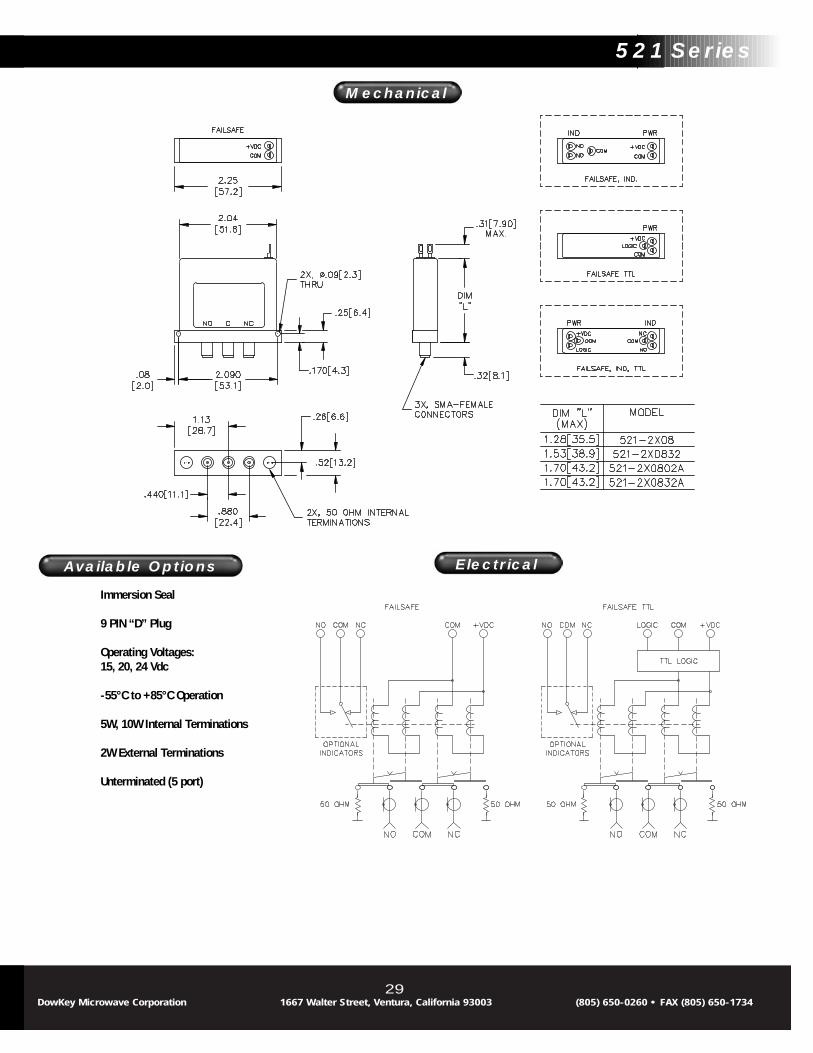
Available Options
29
Immersion Seal
9 PIN “D” Plug
Operating Voltages:15, 20, 24 Vdc
-55°C to +85°C Operation
5W, 10W Internal Terminations
2W External Terminations
Unterminated (5 port)
Available Options
DowKey Microwave Corporation 1667 Walter Street, Ventura, California 93003 (805) 650-0260 • FAX (805) 650-1734
521 Series
Mechanical
Electrical

521 Series Latching
The DowKey Microwave 521 Series 2P3T switches have exceptionalisolation and low insertion loss. These characteristics offer uniqueadvantages for switch matrix and critical test applications. The 521features dual balanced actuators to achieve five port signal transfer, orcreate an SPDT switch in which the unused RF input is internally con-nected to a 2 Watt 50 Ohm termination.
Due to the small size of these switches, only the SMA connectors areavailable. Latching switches with logic include an electronic self-cutoffcircuit and coil suppression diodes.
Typical applications for the 521 Series include:• Automatic Test Equipment• Compact Switch Matrixes• VXI Switch Cards
Frequency VSWR Isolation Ins. Loss RF PowerGHz (max) dB (min) dB (max) Watts (CW)
0-4 1.20 70 0.20 1004-8 1.30 65 0.30 70
8-12 1.40 60 0.40 6012-18 1.50 60 0.50 45
RF Characteristics
Nominal Coil Connector Standard with MechanicalVoltage Type Indicators
12 Vdc SMA 521-420803 521-42083328 Vdc SMA 521-430803 521-430833
Latching Self Cutoff, TTL compatible logic12 Vdc SMA 521-420803A 521-420833A28 Vdc SMA 521-430803A 521-430833A
Connectors and Part Numbers
Operating Voltage:(across temperature range)
12 Vdc (11-14 Vdc)28 Vdc (24-32 Vdc)
Coil Current (Nominal):12 Vdc 440 mA28 Vdc 190 mA
Switching Time:20 mS maximum
Operating Temperature:-25ºC to +65ºC
Mechanical Life, Cycles:1 x 10⁶ minimum
Vibration, Operating:10 G RMS, 20-2000 Hz
Mechanical Shock, Non-Operating:50 G, 1/2 Sine11 mS
Nominal Weight:5.0 oz., (142g.)
Specifications :
DowKey® 521 SeriesLatching
30DowKey Microwave Corporation 1667 Walter Street, Ventura, California 93003 (805) 650-0260 • FAX (805) 650-1734
Power handling capability is for through path only. Optional internaltermination is limited to 500 milliwatts dissipation.

Available Options
31
Immersion Seal
9 PIN “D” Plug
Operating Voltages:15, 20, 24 Vdc
-55°C to +85°C Operation
5W, 10W Internal Terminations
2W External Terminations
Unterminated (5 port)
Reverse Polarity
Available Options
DowKey Microwave Corporation 1667 Walter Street, Ventura, California 93003 (805) 650-0260 • FAX (805) 650-1734
521 Series
Mechanical
Electrical

531-561 Series Normally Open Terminated, SMA
The DowKey Microwave 3 to 6 Position Normally Open switch is amulti-position electro-mechanical coaxial switch with SMA connec-tors. The RF characteristics are excellent over the DC-18 GHz frequency range.
Options include extended frequency range up to 26.5 GHz, a “D” typecontrol connector, moisture seal, indicator contacts, suppressionsdiodes, special operating voltages, and TTL or BCD compatibility. Alsoavailable are BMA (Blind Mate) connectors which provide quick instal-lation into modular plug-in systems operating to 18 GHz. The BMAconnectors mate with OSP* female connectors.
*OSP is a registered trademark of M/A COM Omni-Spectra, Inc.
Typical applications for the 531-561 Series include:• Automatic Test Equipment• Switch Matrixes• Multi-Band or Alternate Source Selection
Frequency VSWR Isolation Ins. Loss RF PowerGHz (max) dB (min) dB (max) Watts (CW)
DC-4 1.25 70 0.20 1004-8 1.35 65 0.30 708-12 1.40 60 0.40 60
12-16 1.50 60 0.50 5016-18 1.60 60 0.50 45
RF Characteristics
Connectors and Part Numbers
Operating Voltage:(across temperature range)
12 Vdc (11-14 Vdc)28 Vdc (24-32 Vdc)
Coil Current (Nominal):12 Vdc 324 mA28 Vdc 140 mA
Switching Time:15 mS maximum
Operating Temperature:-25ºC to +65ºC
Mechanical Life, Cycles:1 x 10⁶ minimum
Nominal Weight:11.0 oz., (312g.)
Specifications :
DowKey® 531-561 SeriesNormally Open Terminated,
SMA
32DowKey Microwave Corporation 1667 Walter Street, Ventura, California 93003 (805) 650-0260 • FAX (805) 650-1734
Nominal Coil Connector Switch ConfigurationVoltage Type SP3T SP4T SP6T
12 Vdc SMA 531-520803 541-520803 561-52080328 Vdc SMA 531-530803 541-530803 561-530803
Normally open with indicators12 Vdc SMA 531-520823 541-520823 561-52082328 Vdc SMA 531-530823 541-530823 561-530823
Normally open with TTL Compatible Logic12 Vdc SMA 531-520803A 541-520803A 561-520803A28 Vdc SMA 531-530803A 541-530803A 561-530803A
Normally open with Indicators, TTL Compatible Logic12 Vdc SMA 531-520823A 541-520823A 561-520823A28 Vdc SMA 531-530823A 541-530823A 561-530823A

Available Options
33
Moisture Seal
9 or 15 PIN “D” Plug
BCD Decoding Circuit
Operating Voltages:15, 20, 24 Vdc
-55°C to +85°C Operation
Normally Closed, Position 1
BMA Connectors
Available Options
DowKey Microwave Corporation 1667 Walter Street, Ventura, California 93003 (805) 650-0260 • FAX (805) 650-1734
531-561 Series
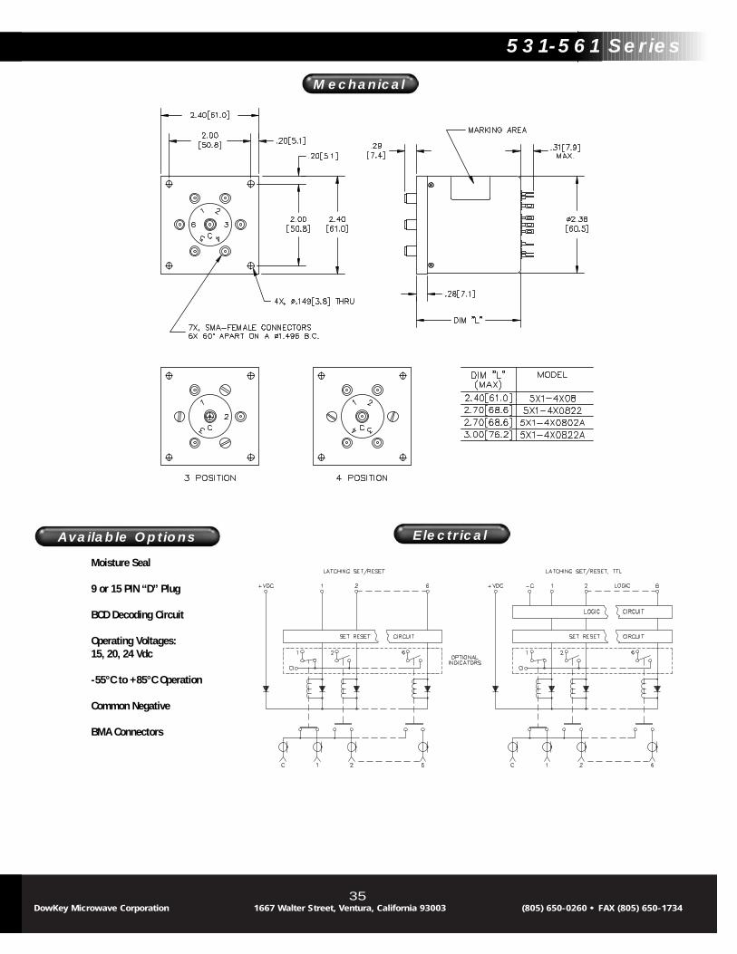
Mechanical
Electrical
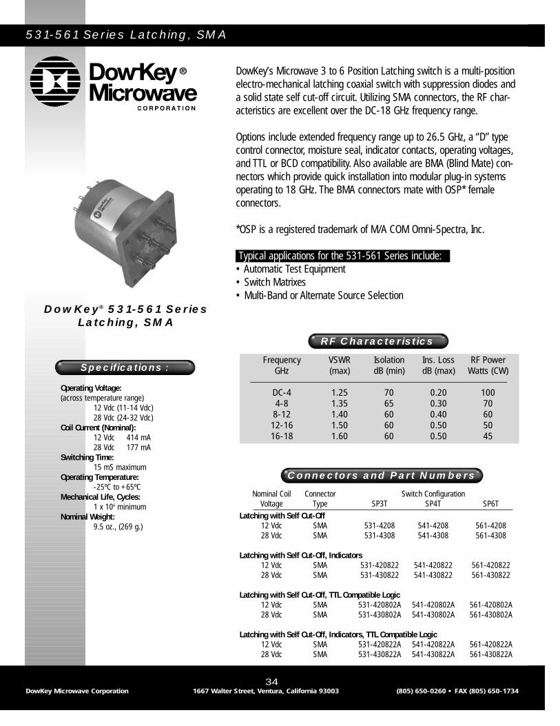
531-561 Series Latching, SMA
DowKey’s Microwave 3 to 6 Position Latching switch is a multi-positionelectro-mechanical latching coaxial switch with suppression diodes anda solid state self cut-off circuit. Utilizing SMA connectors, the RF char-acteristics are excellent over the DC-18 GHz frequency range.
Options include extended frequency range up to 26.5 GHz, a “D” typecontrol connector, moisture seal, indicator contacts, operating voltages,and TTL or BCD compatibility. Also available are BMA (Blind Mate) con-nectors which provide quick installation into modular plug-in systemsoperating to 18 GHz. The BMA connectors mate with OSP* female connectors.
*OSP is a registered trademark of M/A COM Omni-Spectra, Inc.
Typical applications for the 531-561 Series include:• Automatic Test Equipment• Switch Matrixes• Multi-Band or Alternate Source Selection
Frequency VSWR Isolation Ins. Loss RF PowerGHz (max) dB (min) dB (max) Watts (CW)
DC-4 1.25 70 0.20 1004-8 1.35 65 0.30 70
8-12 1.40 60 0.40 6012-16 1.50 60 0.50 5016-18 1.60 60 0.50 45
RF Characteristics
Connectors and Part Numbers
Operating Voltage:(across temperature range)
12 Vdc (11-14 Vdc)28 Vdc (24-32 Vdc)
Coil Current (Nominal):12 Vdc 414 mA28 Vdc 177 mA
Switching Time:15 mS maximum
Operating Temperature:-25ºC to +65ºC
Mechanical Life, Cycles:1 x 10⁶ minimum
Nominal Weight:9.5 oz., (269 g.)
Specifications :
DowKey® 531-561 SeriesLatching, SMA
34DowKey Microwave Corporation 1667 Walter Street, Ventura, California 93003 (805) 650-0260 • FAX (805) 650-1734
Nominal Coil Connector Switch ConfigurationVoltage Type SP3T SP4T SP6T
Latching with Self Cut-Off12 Vdc SMA 531-4208 541-4208 561-420828 Vdc SMA 531-4308 541-4308 561-4308
Latching with Self Cut-Off, Indicators12 Vdc SMA 531-420822 541-420822 561-42082228 Vdc SMA 531-430822 541-430822 561-430822
Latching with Self Cut-Off, TTL Compatible Logic12 Vdc SMA 531-420802A 541-420802A 561-420802A28 Vdc SMA 531-430802A 541-430802A 561-430802A
Latching with Self Cut-Off, Indicators, TTL Compatible Logic12 Vdc SMA 531-420822A 541-420822A 561-420822A28 Vdc SMA 531-430822A 541-430822A 561-430822A
Available Options
35
Moisture Seal
9 or 15 PIN “D” Plug
BCD Decoding Circuit
Operating Voltages:15, 20, 24 Vdc
-55°C to +85°C Operation
Common Negative
BMA Connectors
Available Options
DowKey Microwave Corporation 1667 Walter Street, Ventura, California 93003 (805) 650-0260 • FAX (805) 650-1734
531-561 Series
Mechanical
Electrical
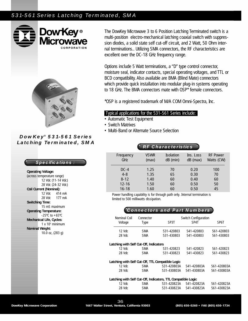
531-561 Series Latching Terminated, SMA
The DowKey Microwave 3 to 6 Position Latching Terminated switch is amulti-position electro-mechanical latching coaxial switch with suppres-sion diodes, a solid state self cut-off circuit, and 2 Watt, 50 Ohm inter-nal terminations.. Utilizing SMA connectors, the RF characteristics areexcellent over the DC-18 GHz frequency range.
Options include 5 Watt terminations, a “D” type control connector,moisture seal, indicator contacts, special operating voltages, and TTL orBCD compatibility. Also available are BMA (Blind Mate) connectorswhich provide quick installation into modular plug-in systems operatingto 18 GHz. The BMA connectors mate with OSP* female connectors.
*OSP is a registered trademark of M/A COM Omni-Spectra, Inc.
Typical applications for the 531-561 Series include:• Automatic Test Equipment• Switch Matrixes• Multi-Band or Alternate Source Selection
Frequency VSWR Isolation Ins. Loss RF PowerGHz (max) dB (min) dB (max) Watts (CW)
DC-4 1.25 70 0.20 1004-8 1.35 65 0.30 70
8-12 1.40 60 0.40 6012-16 1.50 60 0.50 5016-18 1.60 60 0.50 45
RF Characteristics
Connectors and Part Numbers
Operating Voltage:(across temperature range)
12 Vdc (11-14 Vdc)28 Vdc (24-32 Vdc)
Coil Current (Nominal):12 Vdc 414 mA28 Vdc 177 mA
Switching Time:15 mS maximum
Operating Temperature:-25ºC to +65ºC
Mechanical Life, Cycles:1 x 10⁶ minimum
Nominal Weight:10.0 oz, (283 g)
Specifications :
DowKey® 531-561 SeriesLatching Terminated, SMA
36DowKey Microwave Corporation 1667 Walter Street, Ventura, California 93003 (805) 650-0260 • FAX (805) 650-1734
Nominal Coil Connector Switch ConfigurationVoltage Type SP3T SP4T SP6T
12 Vdc SMA 531-420803 541-420803 561-42080328 Vdc SMA 531-430803 541-430803 561-430803
Latching with Self Cut-Off, Indicators12 Vdc SMA 531-420823 541-420823 561-42082328 Vdc SMA 531-430823 541-430823 561-430823
Latching with Self Cut-Off, TTL Compatible Logic12 Vdc SMA 531-420803A 541-420803A 561-420803A28 Vdc SMA 531-430803A 541-430803A 561-430803A
Latching with Self Cut-Off, Indicators, TTL Compatible Logic12 Vdc SMA 531-420823A 541-420823A 561-420823A28 Vdc SMA 531-430823A 541-430823A 561-430823A
Power handling capability is for through path only. Internal termination islimited to 500 milliwatts dissipation.

Available Options
37
Moisture Seal
9 or 15 PIN “D” Plug
BCD Decoding Circuit
Operating Voltages:15, 20, 24 Vdc
-55°C to +85°C Operation
BMA Connectors
Available Options
DowKey Microwave Corporation 1667 Walter Street, Ventura, California 93003 (805) 650-0260 • FAX (805) 650-1734
531-561 Series
Mechanical
Electrical

531-561 Series Normally Open, N
The DowKey Microwave 3 to 6 Position Normally Open switch is amulti-position electro-mechanical coaxial switch. The RF characteristicsare excellent over the DC-12.4 GHz frequency range. Available connec-tors include “N” and “TNC”. “BNC” connectors are also available but arenot recommended for use above 1 GHz.
Options include “D” type control connector, moisture seal, indicatorcontacts, suppression diodes, special operating voltages, and TTL orBCD compatibility.
Typical applications for the 531-561 Series include:• Automatic Test Equipment• Switch Matrixes• Multi-Band or Alternate Source Selection
Frequency VSWR Isolation Ins. Loss RF PowerGHz (max) dB (min) dB (max) Watts (CW)
DC-4 1.25 70 0.30 1754-8 1.35 60 0.40 125
8-12.4 1.50 60 0.40 100
RF Characteristics
Connectors and Part Numbers
Operating Voltage:(across temperature range)
12 Vdc (11-14 Vdc)28 Vdc (24-32 Vdc)
Coil Current (Nominal):12 Vdc 100 mA28 Vdc 56 mA
Switching Time:20 mS maximum
Operating Temperature:-25ºC to +65ºC
Mechanical Life, Cycles:1 x 10⁶ minimum
Nominal Weight:17.0 oz., (482g.)
Specifications :
DowKey® 531-561 SeriesNormally Open, N
38DowKey Microwave Corporation 1667 Walter Street, Ventura, California 93003 (805) 650-0260 • FAX (805) 650-1734
Nominal Coil Connector Switch ConfigurationVoltage Type SP3T SP4T SP6T
12 Vdc N 531-5201 541-5201 561-520128 Vdc N 531-5301 541-5301 561-5301
Normally open with Indicators12 Vdc N 531-520122 541-520122 561-52012228 Vdc N 531-530122 541-530122 561-530122
Normally open with TTL Compatible Logic12 Vdc N 531-520102A 541-520102A 561-520102A28 Vdc N 531-530102A 541-530102A 561-530102A
Normally open with Indicators, TTL Compatible Logic12 Vdc N 531-520122A 541-520122A 561-520122A28 Vdc N 531-530122A 541-530122A 561-530122A
Available Options
39
Moisture Seal
9 or 15 PIN “D” Plug
Operating Voltages:15, 20, 24 Vdc
-55°C to +85°C Operation
BCD Decoding Circuit
BNC, TNC Connectors(Consult factory forRF characteristics)
High Power(Consult factory forRF power rating)
Available Options
DowKey Microwave Corporation 1667 Walter Street, Ventura, California 93003 (805) 650-0260 • FAX (805) 650-1734
531-561 Series
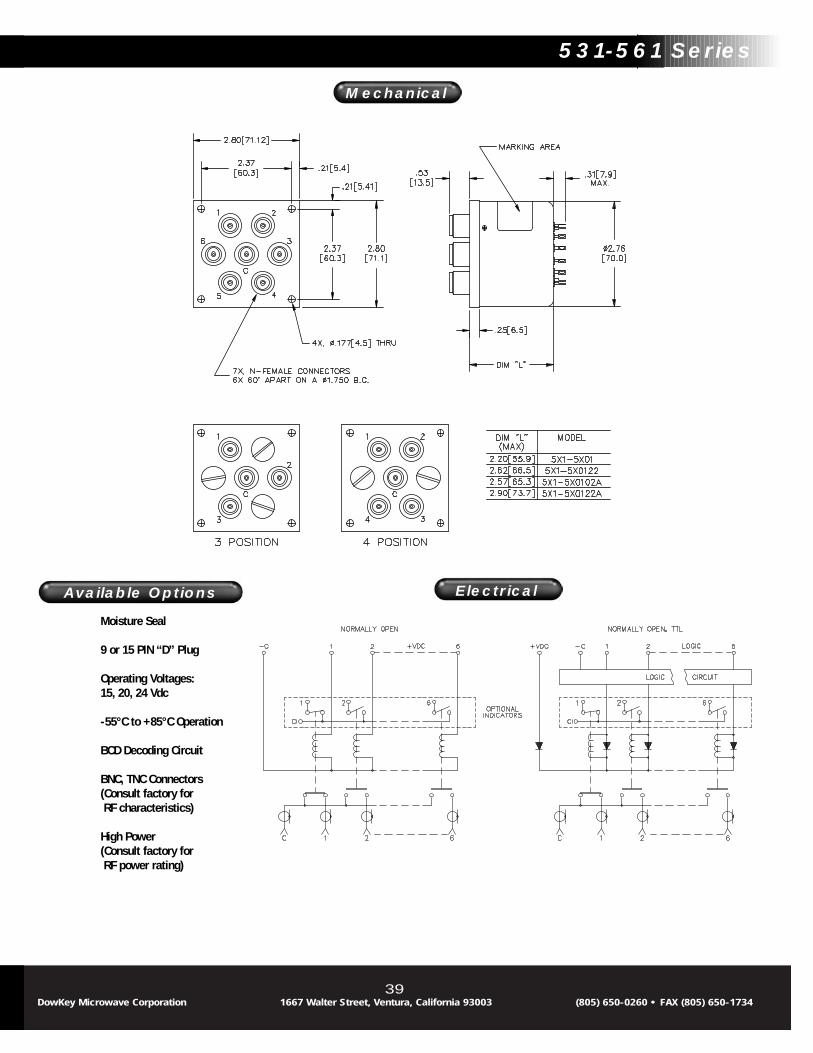
Mechanical
Electrical

531-561 Series Latching, N
DowKey’s Microwave 3 to 6 Position Latching switch is a multi-positionelectro-mechanical coaxial switch with suppression diodes and a solidstate self cut-off circuit. Utilizing “N” and “TNC” connectors, the RFcharacteristics are excellent over the DC-12.4 GHz frequency range.“BNC” connectors are also available but are not recommended for useabove 1 GHz.
Options include “D” type control connector, moisture seal, indicator con-tacts, special operating voltages, and TTL or BCD compatibility.
Typical applications for the 531-561 Series include:• Automatic Test Equipment• Switch Matrixes• Multi-Band or Alternate Source Selection
Frequency VSWR Isolation Ins. Loss RF PowerGHz (max) dB (min) dB (max) Watts (CW)
DC-4 1.25 70 0.30 1754-8 1.35 60 0.40 125
8-12.4 1.50 60 0.50 100
RF Characteristics
Connectors and Part Numbers
Operating Voltage:(across temperature range)
12 Vdc (11-14 Vdc)28 Vdc (24-32 Vdc)
Coil Current (Nominal):12 Vdc 521 mA28 Vdc 224 mA
Switching Time:20 mS maximum
Operating Temperature:-25ºC to +65ºC
Mechanical Life, Cycles:1 x 10⁶ minimum
Nominal Weight:22.0 oz., (624g.)
Specifications :
DowKey® 531-561 SeriesLatching, N
40DowKey Microwave Corporation 1667 Walter Street, Ventura, California 93003 (805) 650-0260 • FAX (805) 650-1734
Nominal Coil Connector Switch ConfigurationVoltage Type SP3T SP4T SP6T
12 Vdc N 531-4201 541-4201 561-420128 Vdc N 531-4301 541-4301 561-4301
Latching with Self Cut-Off, Indicators12 Vdc N 531-420122 541-420122 561-42012228 Vdc N 531-430122 541-430122 561-430122
Latching with Self Cut-Off, TTL Compatible Logic12 Vdc N 531-420102A 541-420102A 561-420102A28 Vdc N 531-430102A 541-430102A 561-430102A
Latching with Self Cut-Off, Indicators, TTL Compatible Logic12 Vdc N 531-420122A 541-420122A 561-420122A28 Vdc N 531-430122A 541-430122A 561-430122A

Available Options
41
Moisture Seal
9 or 15 PIN “D” Plug
Operating Voltages:15, 20, 24 Vdc
-55°C to +85°C Operation
BCD Decoding Circuit
Common Negative
BNC, TNC Connectors(Consult factory forRF characteristics)
High Power(Consult factory forRF power rating)
Available Options
DowKey Microwave Corporation 1667 Walter Street, Ventura, California 93003 (805) 650-0260 • FAX (805) 650-1734
531-561 Series
Mechanical
Electrical

535-565 Series Normally Open, SMA
The DowKey Microwave 535-565 Series Multi-position switches aredesigned for superior performance in restricted area applications suchas portable military test sets. The switches are the smallest multi-position switches available that conform to the mechanical dimensionsof a MIL-PRF-3928/18 switch. All models have SMA connectors withmechanically captivated center conductors for minimal RF leakage andlow signal loss. Three-, four-, and six-position models are standard.
Typical applications for the 535-565 Series include:• Automatic Test Equipment• Compact Switch Matrixes• Multi-Band or Alternate Source Selection
Frequency VSWR Isolation Ins. Loss RF PowerGHz (max) dB (min) dB (max) Watts (CW)
DC-4 1.25 70 0.20 1004-8 1.35 65 0.30 70
8-12 1.40 60 0.40 6012-18 1.50 60 0.50 45
RF Characteristics
Nominal Coil Connector Switch ConfigurationVoltage Type SP3T SP4T SP6T
12 Vdc SMA 535-5208 545-5208 565-520828 Vdc SMA 535-5308 545-5308 565-5308
Normally open with indicators12 Vdc SMA 535-520822 545-520822 565-52082228 Vdc SMA 535-530822 545-530822 565-530822
Normally open with TTL Compatible Logic12 Vdc SMA 535-520802A 545-520802A 565-520802A28 Vdc SMA 535-530802A 545-530802A 565-530802A
Normally open with indicators, TTL Compatible Logic12 Vdc SMA 535-520822A 545-520822A 565-520822A28 Vdc SMA 535-530822A 545-530822A 565-530822A
Connectors and Part Numbers
Operating Voltage:(across temperature range)
12 Vdc (11-14 Vdc)28 Vdc (24-32 Vdc)
Coil Current (Nominal):12 Vdc 333 mA28 Vdc 161 mA
Switching Time:20 mS maximum
Operating Temperature:-25ºC to +65ºC
Mechanical Life, Cycles:1 x 10⁶ minimum
Nominal Weight:4.0 oz., (115g.)
Specifications :
DowKey® 535-565 SeriesNormally Open, SMA
42DowKey Microwave Corporation 1667 Walter Street, Ventura, California 93003 (805) 650-0260 • FAX (805) 650-1734

Available Options
43
Moisture Seal
9 PIN “D” Plug*
BCD Decoding Circuit
Operating Voltages:15, 20, 24 Vdc
-55°C to +85°C Operation
*”D” Plug not availablewith indicators
Available Options
DowKey Microwave Corporation 1667 Walter Street, Ventura, California 93003 (805) 650-0260 • FAX (805) 650-1734
535-565 Series
Mechanical
Electrical

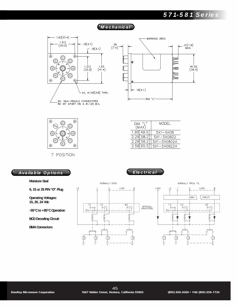
571-581 Series Normally Open, SMA
The DowKey Microwave 7 to 8 Position Normally Open switch is a multi-position electro-mechanical coaxial switch with SMA connectors. The RFcharacteristics are excellent over the DC-18 GHz frequency range.
Options include “D” type control connector, moisture seal, indicator contacts, special operating voltages, suppression diodes, and TTL orBCD compatibility. Also available are BMA (Blind Mate) connectors whichprovide quick installation into modular plug-in systems. The BMA con-nectors mate with OSP* female connectors.
*OSP is a registered trademark of M/A COM Omni-Spectra, Inc.
Typical applications for the 571-581 Series include:• Automatic Test Equipment• Switch Matrixes• Multi-Band or Alternate Source Selection
Frequency VSWR Isolation Ins. Loss RF PowerGHz (max) dB (min) dB (max) Watts (CW)
DC-4 1.25 70 0.20 1004-8 1.35 65 0.30 708-12 1.40 60 0.40 60
12-16 1.50 60 0.50 5016-18 1.80 55 0.80 45
RF Characteristics
Connectors and Part Numbers
Operating Voltage:(across temperature range)
12 Vdc (11-14 Vdc)28 Vdc (24-32 Vdc)
Coil Current (Nominal):12 Vdc 286 mA28 Vdc 122 mA
Switching Time:15 mS maximum
Operating Temperature:-25ºC to +65ºC
Mechanical Life, Cycles:1 x 10⁶ minimum
Nominal Weight:5.0 oz., (142g.)
Specifications :
DowKey® 571-581 SeriesNormally Open, SMA
44DowKey Microwave Corporation 1667 Walter Street, Ventura, California 93003 (805) 650-0260 • FAX (805) 650-1734
Nominal Coil Connector Switch ConfigurationVoltage Type SP7T SP8T
12 Vdc SMA 571-5208 581-520828 Vdc SMA 571-5308 581-5308
Normally Open with Indicators12 Vdc SMA 571-520822 581-52082228 Vdc SMA 571-530822 581-530822
Normally Open with TTL Compatible Logic12 Vdc SMA 571-520802A 581-520802A28 Vdc SMA 571-530802A 581-530802A
Normally Open with Indicators, TTL Compatible Logic12 Vdc SMA 571-520822A 581-520822A28 Vdc SMA 571-530822A 581-530822A
Power handling capability is for through path only. Internal termination islimited to 500 milliwatts dissipation.
Available Options
45
Moisture Seal
9, 15 or 25 PIN “D” Plug
Operating Voltages:15, 20, 24 Vdc
-55°C to +85°C Operation
BCD Decoding Circuit
BMA Connectors
Available Options
DowKey Microwave Corporation 1667 Walter Street, Ventura, California 93003 (805) 650-0260 • FAX (805) 650-1734
571-581 Series
Mechanical
Electrical

571-581 Series Normally Open Terminated, SMA
The DowKey Microwave 7 to 8 Position Normally Open Terminated switch isa multi-position electro-mechanical coaxial switch with SMA connectors and2 Watt, 50 Ohm internal terminations. The RF characteristics are excellentover the DC-18 GHz frequency range.
Options include 5 Watt terminations, a “D” type control connector, moistureseal, indicator contacts, special operating voltages, and TTL or BCD com-patibility. Also available are BMA (Blind Mate) connectors which providequick installation into Modular plug-in systems. The BMA connectors matewith OSP* female connectors.
*OSP is a registered trademark of M/A COM Omni-Spectra, Inc.
Typical applications for the 571-581 series include:• Automatic Test Equipment• Switch Matrixes• Multi-Band or Alternate Source Selection
Frequency VSWR Isolation Ins. Loss RF PowerGHz (max) dB (min) dB (max) Watts (CW)
DC-4-1 1.25 70 0.20 1004-8 1.35 65 0.30 70
8-12 1.40 60 0.40 6012-16 1.50 60 0.50 5016-18 1.80 55 0.80 45
RF Characteristics
Operating Voltage:(across temperature range)
12 Vdc (11-14 Vdc)28 Vdc (24-32 Vdc)
Coil Current (Nominal):12 Vdc 324 mA28 Vdc 140 mA
Switching Time:15 mS maximum
Operating Temperature:-25ºC to +65ºC
Mechanical Life, Cycles:1 x 10⁶ minimum
Nominal Weight:16.5 oz., (468 g)
Specifications :
DowKey® 571-581 SeriesNormally Open Terminated,
SMA
46DowKey Microwave Corporation 1667 Walter Street, Ventura, California 93003 (805) 650-0260 • FAX (805) 650-1734
Connectors and Part NumbersNominal Coil Connector Switch Configuration
Voltage Type SP7T SP8T
12 Vdc SMA 571-520803 581-52080328 Vdc SMA 571-530803 581-530803
Normally Open with Indicators12 Vdc SMA 571-520823 581-52082328 Vdc SMA 571-530823 581-530823
Normally Open with TTL Compatible Logic12 Vdc SMA 571-520803A 581-520803A28 Vdc SMA 571-530803A 581-530803A
Normally Open with Indicators, TTL Compatible Logic12 Vdc SMA 571-520823A 581-520823A28 Vdc SMA 571-530823A 581-530823A
Power handling capability is for through path only. Internal termination islimited to 500 milliwatts dissipation.

Available Options
47
Moisture Seal
15 or 25 PIN “D” Plug
Operating Voltages:15, 20, 24 Vdc
-55°C to +85°C Operation
BCD Decoding Circuit
BMA Connectors
Available Options
DowKey Microwave Corporation 1667 Walter Street, Ventura, California 93003 (805) 650-0260 • FAX (805) 650-1734
571-581 Series
Mechanical
Electrical

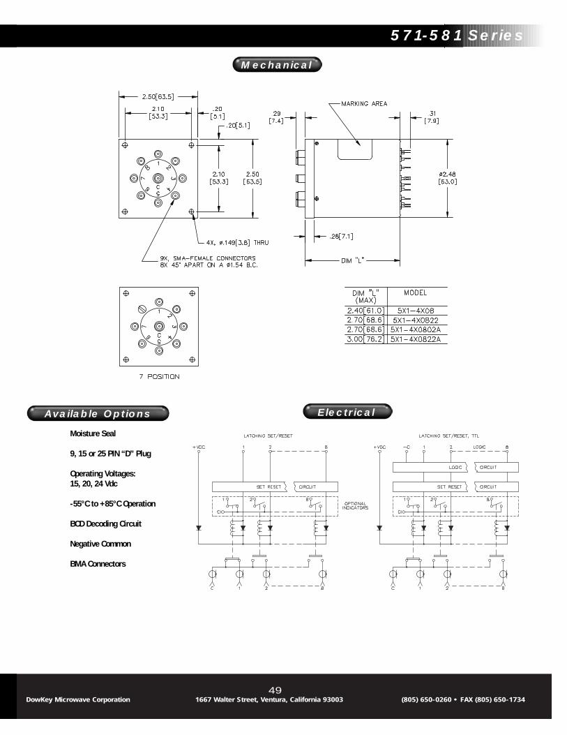
571-581 Series Latching, SMA
The DowKey Microwave 7 to 8 Position Latching switch is a multi-position electro-mechanical coaxial switch with suppression diodes anda solid state self cut-off circuit. Utilizing SMA connectors, the RF char-acteristics are excellent over the DC-18 GHz frequency range.
Options include a “D” type control connector, moisture seal, indicatorcontacts, special operating voltages, and TTL or BCD compatibility. Alsoavailable are BMA (Blind Mate) connectors which provide quick installa-tion into Modular plug-in systems. The BMA connectors mate with OSP*female connectors.
*OSP is a registered trademark of M/A COM Omni-Spectra, Inc.
Typical applications for the 571-581 series include:• Automatic Test Equipment• Switch Matrixes• Multi-Band or Alternate Source Selection• VXI Test Sets
Frequency VSWR Isolation Ins. Loss RF PowerGHz (max) dB (min) dB (max) Watts (CW)
DC-4 1.25 70 0.20 1004-8 1.35 65 0.30 70
8-12 1.40 60 0.40 6012-16 1.50 60 0.50 5016-18 1.80 55 0.80 45
RF Characteristics
Connectors and Part Numbers
Operating Voltage:(across temperature range)
12 Vdc (11-14 Vdc)28 Vdc (24-32 Vdc)
Coil Current (Nominal):12 Vdc 414 mA28 Vdc 158 mA
Switching Time:15 mS maximum
Operating Temperature:-25ºC to +65ºC
Mechanical Life, Cycles:1 x 10⁶ minimum
Nominal Weight:11.2 oz., (317g.)
Specifications :
DowKey® 571-581 SeriesLatching, SMA
48DowKey Microwave Corporation 1667 Walter Street, Ventura, California 93003 (805) 650-0260 • FAX (805) 650-1734
Nominal Coil Connector Switch ConfigurationVoltage Type SP7T SP8T
12 Vdc SMA 571-4208 581-420828 Vdc SMA 571-4308 581-4308
Latching with Self Cut-Off, Indicators12 Vdc SMA 571-420822 581-42082228 Vdc SMA 571-430822 581-430822
Latching with Self Cut-Off, TTL Compatible Logic12 Vdc SMA 571-420802A 581-420802A28 Vdc SMA 571-430802A 581-430802A
Latching with Self Cut-Off, Indicators, TTL Compatible Logic12 Vdc SMA 571-420822A 581-420822A28 Vdc SMA 571-430822A 581-430822A
Available Options
49
Moisture Seal
9, 15 or 25 PIN “D” Plug
Operating Voltages:15, 20, 24 Vdc
-55°C to +85°C Operation
BCD Decoding Circuit
Negative Common
BMA Connectors
Available Options
DowKey Microwave Corporation 1667 Walter Street, Ventura, California 93003 (805) 650-0260 • FAX (805) 650-1734
571-581 Series
Mechanical
Electrical

571-581 Series Latching Terminated, SMA
The DowKey Microwave 7 to 8 Position Latching Terminated switch is amulti-position electro-mechanical coaxial switch with suppressiondiodes and a solid state self cut-off circuit, and 2 Watt, 50 Ohm inter-nal terminations. Utilizing SMA connectors, the RF characteristics areexcellent over the DC-18 GHz frequency range.
Options include 5 Watt terminations, a “D” type control connector,moisture seal, indicator contacts, special operating voltages, and TTLor BCD compatibility. Also available are BMA (Blind Mate) connectorswhich provide quick installation into Modular plug-in systems. The BMAconnectors mate with OSP* female connectors.
*OSP is a registered trademark of M/A COM Omni-Spectra, Inc.
Typical applications for the 571-581 series include:• Automatic Test Equipment• Switch Matrixes• Multi-Band or Alternate Source Selection
Frequency VSWR Isolation Ins. Loss RF PowerGHz (max) dB (min) dB (max) Watts (CW)
DC-4 1.25 70 0.20 1004-8 1.35 65 0.30 70
8-12 1.40 60 0.40 6012-16 1.50 60 0.50 5016-18 1.80 55 0.80 45
RF Characteristics
Connectors and Part Numbers
Operating Voltage:(across temperature range)
12 Vdc (11-14 Vdc)28 Vdc (24-32 Vdc)
Coil Current (Nominal):12 Vdc 414 mA28 Vdc 177 mA
Switching Time:15 mS maximum
Operating Temperature:-25ºC to +65ºC
Mechanical Life, Cycles:1 x 10⁶ minimum
Nominal Weight:14.5 oz., (411g.)
Specifications :
DowKey® 571-581 SeriesLatching Terminated, SMA
50DowKey Microwave Corporation 1667 Walter Street, Ventura, California 93003 (805) 650-0260 • FAX (805) 650-1734
Nominal Coil Connector Switch ConfigurationVoltage Type SP7T SP8T
12 Vdc SMA 571-420803 581-42080328 Vdc SMA 571-430803 581-430803
Latching with Self Cut-Off, Indicators12 Vdc SMA 571-420823 581-42082328 Vdc SMA 571-430823 581-430823
Latching with Self Cut-Off, TTL Compatible Logic12 Vdc SMA 571-420803A 581-420803A28 Vdc SMA 571-430803A 581-430803A
Latching with Self Cut-Off, Indicators, TTL Compatible Logic12 Vdc SMA 571-420823A 581-420823A28 Vdc SMA 571-430823A 581-430823A
Power handling capability is for through path only. Internal termination islimited to 500 milliwatts dissipation.
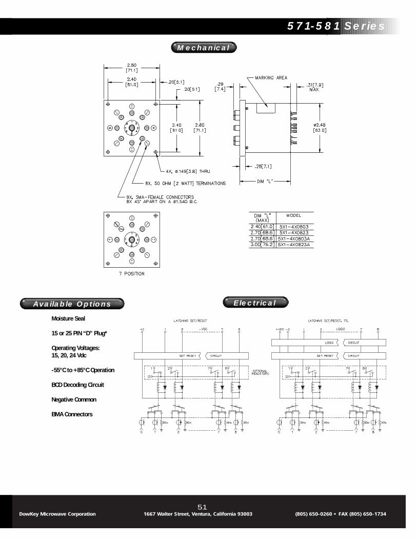
Available Options
51
Moisture Seal
15 or 25 PIN “D” Plug*
Operating Voltages:15, 20, 24 Vdc
-55°C to +85°C Operation
BCD Decoding Circuit
Negative Common
BMA Connectors
Available Options
DowKey Microwave Corporation 1667 Walter Street, Ventura, California 93003 (805) 650-0260 • FAX (805) 650-1734
571-581 Series
Mechanical
Electrical

591-5A1 Series Normally Open, SMA
The DowKey 9 to 10 Position Normally Open switch is a multi-positionelectro-mechanical coaxial switch with SMA connectors. The RF charac-teristics are excellent over the DC-18 GHz frequency range.
Options include a “D” type control connectors, moisture seal, indicatorcontacts, suppression diodes, special operating voltages, and TTL orBCD compatibility. Also available are BMA (Blind Mate) connectorswhich provide quick installation into Modular plug-in systems. The BMAconnectors mate with OSP* female connectors.
*OSP is a registered trademark of M/A COM Omni-Spectra, Inc.
Typical applications for the 591-5A1 series include:• Automatic Test Equipment• Switch Matrixes• Multi-Band or Alternate Source Selection
Frequency VSWR Isolation Ins. Loss RF PowerGHz (max) dB (min) dB (max) Watts (CW)
DC-4 1.25 70 0.20 1004-8 1.35 65 0.30 708-12 1.40 60 0.40 60
12-16 1.50 60 0.6 5016-18 1.80 55 0.80 45
RF Characteristics
Connectors and Part Numbers
Operating Voltage:(across temperature range)
12 Vdc (11-14 Vdc)28 Vdc (24-32 Vdc)
Coil Current (Nominal):12 Vdc 286 mA28 Vdc 122 mA
Switching Time:15 mS maximum
Operating Temperature:-25ºC to +65ºC
Mechanical Life, Cycles:1 x 10⁶ minimum
Nominal Weight:5.5 oz., (156g.)
Specifications :
DowKey® 591-5A1 SeriesNormally Open, SMA
52DowKey Microwave Corporation 1667 Walter Street, Ventura, California 93003 (805) 650-0260 • FAX (805) 650-1734
Nominal Coil Connector Switch ConfigurationVoltage Type SP9T SP10T
12 Vdc SMA 591-5208 5A1-520828 Vdc SMA 591-5308 5A1-5308
Normally Open with Indicators12 Vdc SMA 591-520822 5A1-52082228 Vdc SMA 591-530822 5A1-530822
Normally Open with TTL Compatible Logic12 Vdc SMA 591-520802A 5A1-520802A28 Vdc SMA 591-530802A 5A1-530802A
Normally Open with Indicators, TTL Compatible Logic12 Vdc SMA 591-520822A 5A1-520822A28 Vdc SMA 591-530822A 5A1-530822A

Available Options
53
Moisture Seal
9, 15 or 25 PIN “D” Plug
Operating Voltages:15, 20, 24 Vdc
-55°C to +85°C Operation
BCD Decoding Circuit
BMA Connectors
Available Options
DowKey Microwave Corporation 1667 Walter Street, Ventura, California 93003 (805) 650-0260 • FAX (805) 650-1734
591-5A1 Series
Mechanical
Electrical

591-5A1 Series Normally Open Terminated, SMA
DowKey’s 9 to 10 Position Normally Open switch is a multi-positionelectro-mechanical coaxial switch with SMA connectors. The RF char-acteristics are excellent over the DC-18 GHz frequency range.
Options include a “D” type control connectors, moisture seal, indicatorcontacts, suppression diodes, special operating voltages, and TTL orBCD compatibility. Also available are BMA (Blind Mate) connectorswhich provide quick installation into Modular plug-in systems. The BMAconnectors mate with OSP* female connectors.
*OSP is a registered trademark of M/A COM Omni-Spectra, Inc.
Typical applications for the 591-5A1 Series include:• Automatic Test Equipment• Switch Matrixes• Multi-Band or Alternate Source Selection
Frequency VSWR Isolation Ins. Loss RF PowerGHz (max) dB (min) dB (max) Watts (CW)
DC-4 1.25 70 0.20 1004-8 1.35 65 0.30 708-12 1.40 60 0.40 60
12-16 1.50 60 0.60 5016-18 1.80 55 0.80 45
RF Characteristics
Connectors and Part Numbers
Operating Voltage:(across temperature range)
12 Vdc (11-14 Vdc)28 Vdc (24-32 Vdc)
Coil Current (Nominal):12 Vdc 324 mA28 Vdc 140 mA
Switching Time:15 mS maximum
Operating Temperature:-25ºC to +65ºC
Mechanical Life, Cycles:1 x 10⁶ minimum
Nominal Weight:17.5 oz., (496g.)
Specifications :
DowKey® 591-5A1 SeriesNormally Open Terminated,
SMA
54DowKey Microwave Corporation 1667 Walter Street, Ventura, California 93003 (805) 650-0260 • FAX (805) 650-1734
Nominal Coil Connector Switch ConfigurationVoltage Type SP9T SP10T
12 Vdc SMA 591-520803 5A1-52080328 Vdc SMA 591-530803 5A1-530803
Normally Open with Indicators12 Vdc SMA 591-520823 5A1-52082328 Vdc SMA 591-530823 5A1-530823
Normally Open with TTL Compatible Logic12 Vdc SMA 591-520803A 5A1-520803A28 Vdc SMA 591-530803A 5A1-530803A
Normally Open with Indicators, TTL Compatible Logic12 Vdc SMA 591-520823A 5A1-520823A28 Vdc SMA 591-530823A 5A1-530823A
Power handling capability is for through path only. Internal termination islimited to 500 milliwatts dissipation.

Available Options
55
Moisture Seal
15 or 25 PIN “D” Plug
Operating Voltages:15, 20, 24 Vdc
-55°C to +85°C Operation
BCD Decoding Circuit
BMA Connectors
Available Options
DowKey Microwave Corporation 1667 Walter Street, Ventura, California 93003 (805) 650-0260 • FAX (805) 650-1734
591-5A1 Series
Mechanical
Electrical

591-5A1 Series Latching, SMA
The DowKey 9 to 10 Position Latching switch is a multi-position electro-mechanical coaxial switch with SMA connectors. The RF charac-teristics are excellent over the DC-18 GHz frequency range.
Options include a “D” type control connector, moisture seal, indicatorcontacts, special operating voltages, and TTL or BCD compatibility. Alsoavailable are BMA (Blind Mate) connectors which provide quick installa-tion into Modular plug-in systems. The BMA connectors mate with OSP*female connectors.
*OSP is a registered trademark of M/A COM Omni-Spectra, Inc.
Typical applications for the 591-5A1 Series include:• Automatic Test Equipment• Switch Matrixes• Multi-Band or Alternate Source Selection• VXI Test Sets
Frequency VSWR Isolation Ins. Loss RF PowerGHz (max) dB (min) dB (max) Watts (CW)
DC-4 1.25 70 0.20 1004-8 1.35 65 0.30 70
8-12 1.40 60 0.40 6012-16 1.50 60 0.50 5016-18 1.80 55 0.80 45
RF Characteristics
Connectors and Part Numbers
Operating Voltage:(across temperature range)
12 Vdc (11-14 Vdc)28 Vdc (24-32 Vdc)
Coil Current (Nominal):12 Vdc 414 mA28 Vdc 177 mA
Switching Time:15 mS maximum
Operating Temperature:-25ºC to +65ºC
Mechanical Life, Cycles:1 x 10⁶ minimum
Nominal Weight:14.9 oz., (422g.)
Specifications :
DowKey® 591-5A1 SeriesLatching, SMA
56DowKey Microwave Corporation 1667 Walter Street, Ventura, California 93003 (805) 650-0260 • FAX (805) 650-1734
Nominal Coil Connector Switch ConfigurationVoltage Type SP9T SP10T
12 Vdc SMA 591-4208 5A1-420828 Vdc SMA 591-4308 5A1-4308
Latching with Self Cut-Off, Indicators12 Vdc SMA 591-420822 5A1-42082228 Vdc SMA 591-430822 5A1-430822
Latching with Self Cut-Off, TTL Compatible Logic12 Vdc SMA 591-420802A 5A1-420802A28 Vdc SMA 591-430802A 5A1-430802A
Latching with Self Cut-Off, Indicators, TTL Compatible Logic12 Vdc SMA 591-420822A 5A1-420822A28 Vdc SMA 591-430822A 5A1-430822A

Available Options
57
Moisture Seal
15 or 25 PIN “D” Plug
Operating Voltages:15, 20, 24 Vdc
-55°C to +85°C Operation
BCD Decoding Circuit
Negative Common
BMA Connectors
Available Options
DowKey Microwave Corporation 1667 Walter Street, Ventura, California 93003 (805) 650-0260 • FAX (805) 650-1734
591-5A1 Series
Mechanical
Electrical

591-5A1 Series Latching Terminated, SMA
The DowKey 9 to 10 Position Latching Terminated switch is a multi-position electro-mechanical coaxial switch with suppression diodes anda solid state self cut-off circuit. Utilizing SMA connectors, the RF char-acteristics are excellent over the DC-18 GHz frequency range.
Options include a “D” type control connector, moisture seal, indicatorcontacts, special operating voltages, and TTL or BCD compatibility. Alsoavailable are BMA (Blind Mate) connectors which provide quick installa-tion into Modular plug-in systems. The BMA connectors mate with OSP*female connectors.
*OSP is a registered trademark of M/A COM Omni-Spectra, Inc.
Typical applications for the 591-5A1 Series include:• Automatic Test Equipment• Switch Matrixes• Multi-Band or Alternate Source Selection
Frequency VSWR Isolation Ins. Loss RF PowerGHz (max) dB (min) dB (max) Watts (CW)
DC-4 1.25 70 0.20 1004-8 1.35 65 0.30 708-12 1.40 60 0.40 60
12-16 1.50 60 0.60 5016-18 1.80 55 0.80 45
RF Characteristics
Connectors and Part Numbers
Operating Voltage:(across temperature range)
12 Vdc (11-14 Vdc)28 Vdc (24-32 Vdc)
Coil Current (Nominal):12 Vdc 414 mA28 Vdc 177 mA
Switching Time:15 mS maximum
Operating Temperature:-25ºC to +65ºC
Mechanical Life, Cycles:1 x 10⁶ minimum
Nominal Weight:15.3 oz., (434g.)
Specifications :
DowKey® 591-5A1 SeriesLatching Terminated, SMA
58DowKey Microwave Corporation 1667 Walter Street, Ventura, California 93003 (805) 650-0260 • FAX (805) 650-1734
Nominal Coil Connector Switch ConfigurationVoltage Type SP9T SP10T
12 Vdc SMA 591-420803 5A1-42080328 Vdc SMA 591-430803 5A1-430803
Latching with Self Cut-Off, Indicators12 Vdc SMA 591-420823 5A1-42082328 Vdc SMA 591-430823 5A1-430823
Latching with Self Cut-Off, TTL Compatible Logic12 Vdc SMA 591-420803A 5A1-420803A28 Vdc SMA 591-430803A 5A1-430803A
Latching with Self Cut-Off, Indicators, TTL Compatible Logic12 Vdc SMA 591-420823A 5A1-420823A28 Vdc SMA 591-430823A 5A1-430823A
Power handling capability is for through path only. Internal termination islimited to 500 milliwatts dissipation.

Available Options
59
Moisture Seal
15 or 25 PIN “D” Plug
Operating Voltages:15, 20, 24 Vdc
-55°C to +85°C Operation
BCD Decoding Circuit
Negative Common
BMA Connectors
Available Options
DowKey Microwave Corporation 1667 Walter Street, Ventura, California 93003 (805) 650-0260 • FAX (805) 650-1734
591-5A1 Series
Mechanical
Electrical
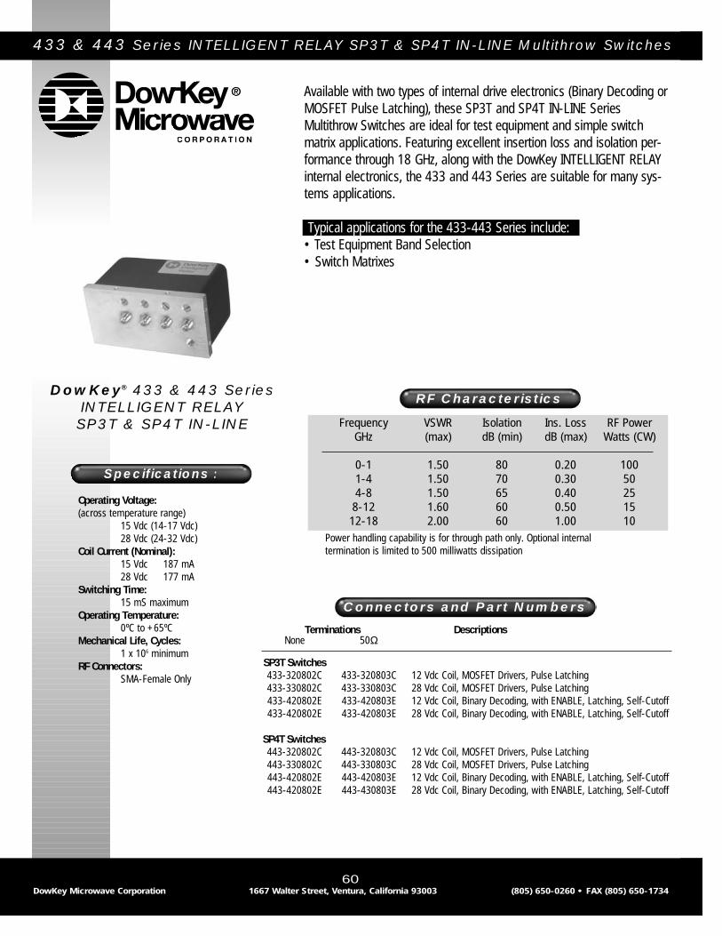
433 & 443 Series INTELLIGENT RELAY SP3T & SP4T IN-LINE Multithrow Switches
Available with two types of internal drive electronics (Binary Decoding orMOSFET Pulse Latching), these SP3T and SP4T IN-LINE SeriesMultithrow Switches are ideal for test equipment and simple switchmatrix applications. Featuring excellent insertion loss and isolation per-formance through 18 GHz, along with the DowKey INTELLIGENT RELAYinternal electronics, the 433 and 443 Series are suitable for many sys-tems applications.
Typical applications for the 433-443 Series include:• Test Equipment Band Selection• Switch Matrixes
Frequency VSWR Isolation Ins. Loss RF PowerGHz (max) dB (min) dB (max) Watts (CW)
0-1 1.50 80 0.20 1001-4 1.50 70 0.30 504-8 1.50 65 0.40 258-12 1.60 60 0.50 15
12-18 2.00 60 1.00 10
RF Characteristics
Terminations DescriptionsNone 50Ω
SP3T Switches433-320802C 433-320803C 12 Vdc Coil, MOSFET Drivers, Pulse Latching433-330802C 433-330803C 28 Vdc Coil, MOSFET Drivers, Pulse Latching433-420802E 433-420803E 12 Vdc Coil, Binary Decoding, with ENABLE, Latching, Self-Cutoff433-420802E 433-420803E 28 Vdc Coil, Binary Decoding, with ENABLE, Latching, Self-Cutoff
SP4T Switches443-320802C 443-320803C 12 Vdc Coil, MOSFET Drivers, Pulse Latching443-330802C 443-330803C 28 Vdc Coil, MOSFET Drivers, Pulse Latching443-420802E 443-420803E 12 Vdc Coil, Binary Decoding, with ENABLE, Latching, Self-Cutoff443-420802E 443-430803E 28 Vdc Coil, Binary Decoding, with ENABLE, Latching, Self-Cutoff
Connectors and Part Numbers
DowKey® 433 & 443 SeriesINTELLIGENT RELAY SP3T & SP4T IN-LINE
60DowKey Microwave Corporation 1667 Walter Street, Ventura, California 93003 (805) 650-0260 • FAX (805) 650-1734
Power handling capability is for through path only. Optional internaltermination is limited to 500 milliwatts dissipation
Operating Voltage:(across temperature range)
15 Vdc (14-17 Vdc)28 Vdc (24-32 Vdc)
Coil Current (Nominal):15 Vdc 187 mA28 Vdc 177 mA
Switching Time:15 mS maximum
Operating Temperature:0ºC to +65ºC
Mechanical Life, Cycles:1 x 10⁶ minimum
RF Connectors:SMA-Female Only
Specifications :

61DowKey Microwave Corporation 1667 Walter Street, Ventura, California 93003 (805) 650-0260 • FAX (805) 650-1734
433 & 443 Series
Mechanical
Electrical
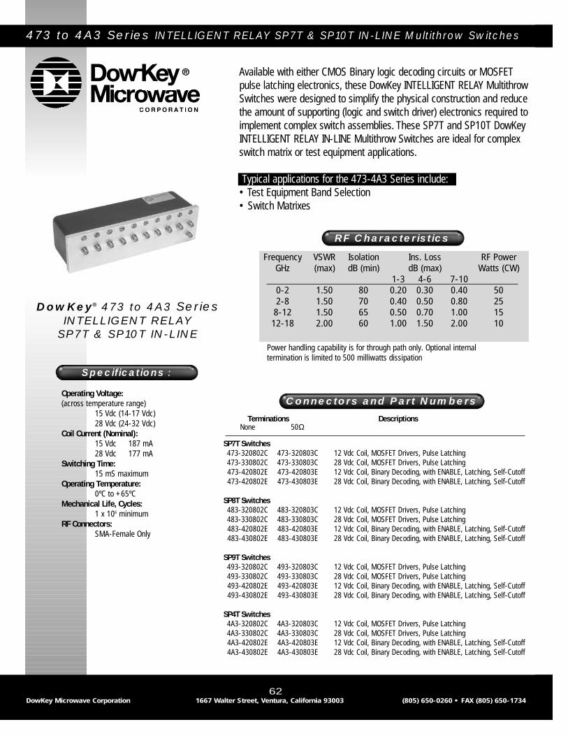
473 to 4A3 Series INTELLIGENT RELAY SP7T & SP10T IN-LINE Multithrow Switches
DowKey® 473 to 4A3 SeriesINTELLIGENT RELAY
SP7T & SP10T IN-LINE
62DowKey Microwave Corporation 1667 Walter Street, Ventura, California 93003 (805) 650-0260 • FAX (805) 650-1734
Frequency VSWR Isolation Ins. Loss RF PowerGHz (max) dB (min) dB (max) Watts (CW)
1-3 4-6 7-100-2 1.50 80 0.20 0.30 0.40 502-8 1.50 70 0.40 0.50 0.80 25
8-12 1.50 65 0.50 0.70 1.00 1512-18 2.00 60 1.00 1.50 2.00 10
RF Characteristics
Terminations DescriptionsNone 50Ω
SP7T Switches473-320802C 473-320803C 12 Vdc Coil, MOSFET Drivers, Pulse Latching473-330802C 473-330803C 28 Vdc Coil, MOSFET Drivers, Pulse Latching473-420802E 473-420803E 12 Vdc Coil, Binary Decoding, with ENABLE, Latching, Self-Cutoff473-420802E 473-430803E 28 Vdc Coil, Binary Decoding, with ENABLE, Latching, Self-Cutoff
SP8T Switches483-320802C 483-320803C 12 Vdc Coil, MOSFET Drivers, Pulse Latching483-330802C 483-330803C 28 Vdc Coil, MOSFET Drivers, Pulse Latching483-420802E 483-420803E 12 Vdc Coil, Binary Decoding, with ENABLE, Latching, Self-Cutoff483-430802E 483-430803E 28 Vdc Coil, Binary Decoding, with ENABLE, Latching, Self-Cutoff
SP9T Switches493-320802C 493-320803C 12 Vdc Coil, MOSFET Drivers, Pulse Latching493-330802C 493-330803C 28 Vdc Coil, MOSFET Drivers, Pulse Latching493-420802E 493-420803E 12 Vdc Coil, Binary Decoding, with ENABLE, Latching, Self-Cutoff493-430802E 493-430803E 28 Vdc Coil, Binary Decoding, with ENABLE, Latching, Self-Cutoff
SP4T Switches4A3-320802C 4A3-320803C 12 Vdc Coil, MOSFET Drivers, Pulse Latching4A3-330802C 4A3-330803C 28 Vdc Coil, MOSFET Drivers, Pulse Latching4A3-420802E 4A3-420803E 12 Vdc Coil, Binary Decoding, with ENABLE, Latching, Self-Cutoff4A3-430802E 4A3-430803E 28 Vdc Coil, Binary Decoding, with ENABLE, Latching, Self-Cutoff
Connectors and Part Numbers
Power handling capability is for through path only. Optional internaltermination is limited to 500 milliwatts dissipation
Available with either CMOS Binary logic decoding circuits or MOSFETpulse latching electronics, these DowKey INTELLIGENT RELAY MultithrowSwitches were designed to simplify the physical construction and reducethe amount of supporting (logic and switch driver) electronics required toimplement complex switch assemblies. These SP7T and SP10T DowKeyINTELLIGENT RELAY IN-LINE Multithrow Switches are ideal for complexswitch matrix or test equipment applications.
Typical applications for the 473-4A3 Series include:• Test Equipment Band Selection• Switch Matrixes
Operating Voltage:(across temperature range)
15 Vdc (14-17 Vdc)28 Vdc (24-32 Vdc)
Coil Current (Nominal):15 Vdc 187 mA28 Vdc 177 mA
Switching Time:15 mS maximum
Operating Temperature:0ºC to +65ºC
Mechanical Life, Cycles:1 x 10⁶ minimum
RF Connectors:SMA-Female Only
Specifications :

63DowKey Microwave Corporation 1667 Walter Street, Ventura, California 93003 (805) 650-0260 • FAX (805) 650-1734
473 to 4A3 Series
Mechanical
Electrical
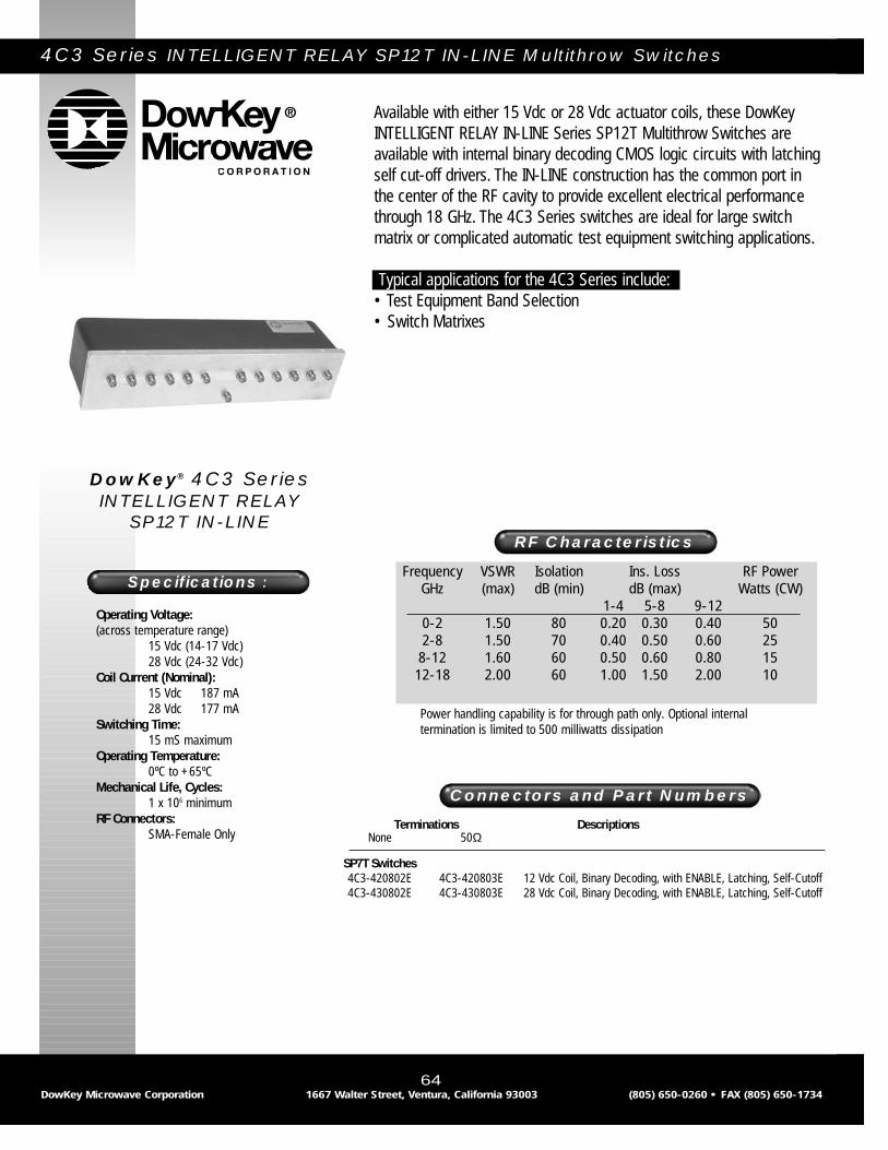
4C3 Series INTELLIGENT RELAY SP12T IN-LINE Multithrow Switches
DowKey® 4C3 Series INTELLIGENT RELAY
SP12T IN-LINE
64DowKey Microwave Corporation 1667 Walter Street, Ventura, California 93003 (805) 650-0260 • FAX (805) 650-1734
RF Characteristics
Terminations DescriptionsNone 50Ω
SP7T Switches4C3-420802E 4C3-420803E 12 Vdc Coil, Binary Decoding, with ENABLE, Latching, Self-Cutoff4C3-430802E 4C3-430803E 28 Vdc Coil, Binary Decoding, with ENABLE, Latching, Self-Cutoff
Connectors and Part Numbers
Power handling capability is for through path only. Optional internaltermination is limited to 500 milliwatts dissipation
Available with either 15 Vdc or 28 Vdc actuator coils, these DowKeyINTELLIGENT RELAY IN-LINE Series SP12T Multithrow Switches areavailable with internal binary decoding CMOS logic circuits with latchingself cut-off drivers. The IN-LINE construction has the common port inthe center of the RF cavity to provide excellent electrical performancethrough 18 GHz. The 4C3 Series switches are ideal for large switchmatrix or complicated automatic test equipment switching applications.
Typical applications for the 4C3 Series include:• Test Equipment Band Selection• Switch Matrixes
Operating Voltage:(across temperature range)
15 Vdc (14-17 Vdc)28 Vdc (24-32 Vdc)
Coil Current (Nominal):15 Vdc 187 mA28 Vdc 177 mA
Switching Time:15 mS maximum
Operating Temperature:0ºC to +65ºC
Mechanical Life, Cycles:1 x 10⁶ minimum
RF Connectors:SMA-Female Only
Specifications :Frequency VSWR Isolation Ins. Loss RF Power
GHz (max) dB (min) dB (max) Watts (CW)1-4 5-8 9-12
0-2 1.50 80 0.20 0.30 0.40 502-8 1.50 70 0.40 0.50 0.60 25
8-12 1.60 60 0.50 0.60 0.80 1512-18 2.00 60 1.00 1.50 2.00 10

65DowKey Microwave Corporation 1667 Walter Street, Ventura, California 93003 (805) 650-0260 • FAX (805) 650-1734
4C3 Series
Mechanical
Electrical

46 Series DPDT Switch
This DPDT switch is two SPDT relays (similar to the DowKey 164Series) mounted together on a common plate with a single actuatingcoil. The connectors are all opposite the mounting surface, allowingeasy access and flush-mount capability. With excellent RF performance,this low cost dual relay is suitable for most general purpose switchingapplications.
Typical applications for the 46 Series include:• RF and Microwave Communications• Dual-Monitor Video Switching• Magnetic Resonance Imaging Systems• RF and Video Switching
Frequency VSWR Isolation Ins. Loss RF PowerMHz (max) dB (min) dB (max) Watts (CW)
0-50 1.03 60 0.03 15050-100 1.05 52 0.04 150-125100-200 1.07 45 0.05 125-100200-400 1.12 40 0.10 100-75
400-1,000 1.20 30 0.15 75-50
RF Characteristics
Nominal Coil Connector StandardVoltage Type
12 Vdc BNC 46-220228 Vdc BNC 46-2302115 Vac BNC 46-2602
12 Vdc TNC 46-220328 Vdc TNC 46-2303115 Vac TNC 46-2603
Connectors and Part Numbers
Operating Voltage:(across temperature range)
12 Vdc (11-14 Vdc)28 Vdc (24-32 Vdc)
Coil Current (Nominal):12 Vdc 250 mA28 Vdc 114 mA
Operate Time:20 mS maximum
Operating Temperature:0ºC to +65ºC
Mechanical Life, Cycles:1 x 10⁶ minimum
Nominal Weight:9.5 oz., (270g.)
Specifications :
DowKey® 46 Series DPDT Switch
66DowKey Microwave Corporation 1667 Walter Street, Ventura, California 93003 (805) 650-0260 • FAX (805) 650-1734

67DowKey Microwave Corporation 1667 Walter Street, Ventura, California 93003 (805) 650-0260 • FAX (805) 650-1734
46 Series
Mechanical
Electrical
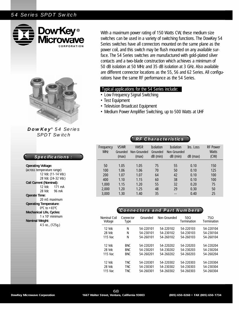
54 Series SPDT Switch
With a maximum power rating of 150 Watts CW, these medium sizeswitches can be used in a variety of switching functions. The DowKey 54Series switches have all connectors mounted on the same plane as thepower coil, and this switch may be flush mounted on any available sur-face. The 54 Series switches are manufactured with gold-plated silvercontacts and a two-blade construction which achieves a minimum of 50 dB isolation at 50 MHz and 35 dB isolation at 3 GHz. Also availableare different connector locations as the 55, 56 and 62 Series. All configu-rations have the same RF performance as the 54 Series.
Typical applications for the 54 Series include:• Low Frequency Signal Switching• Test Equipment• Television Broadcast Equipment• Medium Power Amplifier Switching, up to 500 Watts at UHF
Frequency VSWR VWSR Isolation Isolation Ins. Loss RF PowerMHz Grounded Non-Grounded Grounded Non-Grounded Watts
(max) (max) dB (min) dB (min) dB (max) (CW)
50 1.05 1.05 75 55 0.10 150100 1.06 1.06 70 50 0.10 125200 1.07 1.07 64 42 0.10 100400 1.10 1.15 60 38 0.10 100
1,000 1.15 1.20 55 32 0.20 752,000 1.20 1.25 48 29 0.30 503,000 1.30 1.40 35 -- 0.40 25
RF Characteristics
Operating Voltage:(across temperature range)
12 Vdc (11-14 Vdc)28 Vdc (24-32 Vdc)
Coil Current (Nominal):12 Vdc 171 mA28 Vdc 96 mA
Operate Time:20 mS maximum
Operating Temperature:0ºC to +65ºC
Mechanical Life, Cycles:1 x 10⁶ minimum
Nominal Weight:4.5 oz., (125g.)
Specifications :
DowKey® 54 Series SPDT Switch
68DowKey Microwave Corporation 1667 Walter Street, Ventura, California 93003 (805) 650-0260 • FAX (805) 650-1734
Nominal Coil Connector Grounded Non-Grounded 50Ω 75ΩVoltage Type Termination Termination
12 Vdc N 54-220101 54-220102 54-220103 54-22010428 Vdc N 54-230101 54-230102 54-230103 54-230104115 Vac N 54-260101 54-260102 54-260103 54-260104
12 Vdc BNC 54-220201 54-220202 54-220203 54-22020428 Vdc BNC 54-230201 54-230202 54-230203 54-230204115 Vac BNC 54-260201 54-260202 54-260203 54-260204
12 Vdc TNC 54-220301 54-220302 54-220303 54-22030428 Vdc TNC 54-230301 54-230302 54-230303 54-230304115 Vac TNC 54-260301 54-260302 54-260303 54-260304
Connectors and Part Numbers

Available Options
69
Available Options
DowKey Microwave Corporation 1667 Walter Street, Ventura, California 93003 (805) 650-0260 • FAX (805) 650-1734
54 Series
Mechanical
Electrical
55 Series
56 Series
62 Series

60 Series SPDT Switch
The DowKey 60 Series coaxial relays are ruggedly constructed anddesigned for operation to a maximum power level of 1 kilowatt. Theyhave been the standard for air traffic control and two way radio systemsfor over forty years.
Also available in the 60 Series is a patented, high isolation option (“G”option) for transmit-receive applications. This option leaves the unusedinput open, and increases the isolation on the N/C connector to 85 dBat frequencies up to 500 MHz. This option reduces the maximum powerrating of the N/C connector to 20 Watts, and will increase the VSWR ofthis terminal above approximately 400 MHz. They are available with orwithout two form “C” auxiliary contacts.
Typical applications for the 60 Series include:• Transmit-Receive Switching• Communication Antenna Switching• Video Switching• Hot Standby Transmitters or Receivers
Frequency VSWR Isolation Ins. Loss RF PowerMHz (max) dB (min) dB (max) Watts (CW)
50 1.10 40 0.10 1,000100 1.15 35 0.15 1,000400 1.30 25 0.20 500
1,000 1.60 20 0.25 350
RF Characteristics
Connectors and Part Numbers
Operating Voltage:(across temperature range)
12 Vdc (11-14 Vdc)28 Vdc (24-32 Vdc)
Coil Current (Nominal):12 Vdc 250 mA28 Vdc 108 mA
Operate Time:20 mS maximum
Operating Temperature:0ºC to +65ºC
Mechanical Life, Cycles:1 x 10⁶ minimum
Nominal Weight:12.0 oz., (340g.)
Specifications :
DowKey® 60 Series SPDT Switch
70DowKey Microwave Corporation 1667 Walter Street, Ventura, California 93003 (805) 650-0260 • FAX (805) 650-1734
Nominal Coil Connector SPDT SPDT w/DPDT “G” Option “G” OptionVoltage Type Aux. Contacts w/DPDT Aux. Con.
12 Vdc N 60-2201 60-220142 60-2225 60-22254228 Vdc N 60-2301 60-230142 60-2325 60-232542115 Vac N 60-2601 60-260142 60-2625 60-262542
12 Vdc BNC 60-2202 60-220242 60-2226 60-22264228 Vdc BNC 60-2302 60-230242 60-2326 60-232642115 Vac BNC 60-2602 60-260242 60-2626 60-262642
12 Vdc UHF* 60-2204 60-220442 60-2228 60-22284228 Vdc UHF* 60-2304 60-230442 60-2328 60-232842115 Vac UHF* 60-2604 60-260442 60-2628 60-262842
*Not recommended for applications above 300 MHz.
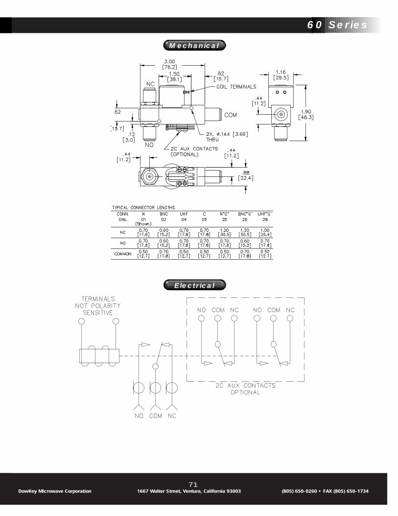
71DowKey Microwave Corporation 1667 Walter Street, Ventura, California 93003 (805) 650-0260 • FAX (805) 650-1734
60 Series
Mechanical
Electrical

63 Series SPDT Failsafe Switches
The DowKey 63 Series SPDT Failsafe Relay provides an enclosed actua-tor for use in environments where dust or moisture may be encountered.
Typical applications for the 63 Series include:• ILS Air Traffic Control Equipment• UHF/UHF Standby Transmitters and Receivers
Frequency VSWR Isolation Ins. Loss RF PowerGHz (max) dB (min) dB (max) Watts (CW)
0-.5 1.10 70 0.10 150-100.5-2 1.30 50 0.20 100-752-3 1.40 45 0.30 75-50
RF Characteristics
Nominal Coil Connector Failsafe StandardVoltage Type SPDT
12 Vdc N 63-220128 Vdc N 63-2301
Connectors and Part Numbers
Operating Voltage:(across temperature range)
12 Vdc (11-14 Vdc)28 Vdc (24-32 Vdc)
Coil Current (Nominal):12 Vdc 255 mA28 Vdc 112 mA
Operate Time:20 mS maximum
Operating Temperature:-25ºC to +65ºC
Mechanical Life, Cycles:1 x 10⁶ minimum
Nominal Weight:6.0 oz., (170g.)
Specifications :
DowKey® 63 Series SPDT Failsafe Switches
72DowKey Microwave Corporation 1667 Walter Street, Ventura, California 93003 (805) 650-0260 • FAX (805) 650-1734

73DowKey Microwave Corporation 1667 Walter Street, Ventura, California 93003 (805) 650-0260 • FAX (805) 650-1734
63 Series
Mechanical
Electrical

64 Series Transfer Relay
The DowKey 64 Series SPDT Transfer Failsafe Relay provides anenclosed actuator for use in environments where dust or moisture maybe encountered.
Typical applications for the 64 Series include:• ILS Air Traffic Control Equipment• UHF/UHF Standby Transmitters and Receivers
Frequency VSWR Isolation Ins. Loss RF PowerGHz (max) dB (min) dB (max) Watts (CW)
0-0.5 1.10 30 0.10 150-1000.5-1.5 1.20 25 0.20 100-501.5-3.0 1.40 20 0.40 50-25
RF Characteristics
Nominal Coil Connector Failsafe StandardVoltage Type Transfer
12 Vdc N 64-220128 Vdc N 64-2301
Connectors and Part Numbers
Operating Voltage:(across temperature range)
12 Vdc (11-14 Vdc)28 Vdc (24-32 Vdc)
Coil Current (Nominal):12 Vdc 255 mA28 Vdc 112 mA
Operate Time:20 mS maximum
Operating Temperature:-25ºC to +65ºC
Mechanical Life, Cycles:1 x 10⁶ minimum
Nominal Weight:7.0 oz., (198g.)
Specifications :
DowKey® 64 Series Transfer Relay
74DowKey Microwave Corporation 1667 Walter Street, Ventura, California 93003 (805) 650-0260 • FAX (805) 650-1734

75DowKey Microwave Corporation 1667 Walter Street, Ventura, California 93003 (805) 650-0260 • FAX (805) 650-1734
64 Series
Mechanical
Electrical

66 Series SPDT Switch
The DowKey 66 Series switch was developed to meet high isolationswitching requirements of the cable television industry. Isolation ofgreater than 90 dB is achieved up to 500 MHz through the unique 75 Ohm connectors, which have a double break design to completelyisolate the unused input from the RF cavity, leaving the input lead open(not grounded). The relay is designed for baseband video source switch-ing, using the auxiliary contacts for audio signals. The 66 Series can beused for a variety of studio switching applications, eliminating the needto stock more than one type of relay.
Typical applications for the 66 Series include:• IF Switching• UHF/VHF Channel Switching• Studio or Cable Head-End• Video Source Selection
Frequency VSWR Isolation Ins. Loss RF PowerMHz (max) dB (min) dB (max) Watts (CW)
50 1.05 100 0.04 100100 1.10 100 0.06 100300 1.30 95 0.10 40500 1.65 90 0.20 20
RF Characteristics
Nominal Coil Connector Standard SPDT with 2Voltage Type SPDT “C” Contacts
12 Vdc F* 66-2272 66-22724226.5 Vdc F* 66-2372 66-237242
Connectors and Part Numbers
Operating Voltage:(across temperature range)
12 Vdc (11-14 Vdc)26.5 Vdc (24-32 Vdc)
Coil Current (Nominal):12 Vdc 265 mA26.5 Vdc 150 mA
Operate Time:25 mS maximum
Operating Temperature:0ºC to +65ºC
Mechanical Life, Cycles:1 x 10⁶ minimum
Nominal Weight:10.0 oz., (283g.)
Specifications :
DowKey® 66 Series SPDT Switch
76DowKey Microwave Corporation 1667 Walter Street, Ventura, California 93003 (805) 650-0260 • FAX (805) 650-1734
* Not recommended for use with RG-6 cable.

77DowKey Microwave Corporation 1667 Walter Street, Ventura, California 93003 (805) 650-0260 • FAX (805) 650-1734
66 Series
Mechanical
Electrical

77 Series SPDT Switch
These medium size, light-weight relays are designed and manufacturedwith gold plated RF contacts and silver plated outer conductors whichgive good RF performance to 1 GHz (Isolation is greater than 30 dB,Insertion loss is less than 0.15 dB). Available with either 50 Ohm BNCconnectors or 75 Ohm type “F” connectors, the “T” shaped configura-tion has the common connector at one end of the RF cavity block andthe N/O and N/C connectors 180° apart on the opposite end. Otheroptions include type TNC connectors.
Typical applications for the 77 Series include:• Military Communications• Commercial and Industrial Communications• CATV/MATV/CCTV Switching
Frequency VSWR Isolation Ins. Loss RF PowerMHz (max) dB (min) dB (max) Watts (CW)
50 1.05 50 0.03 150100 1.10 45 0.04 100400 1.20 40 0.10 75
1,000 1.50 30 0.15 50
RF Characteristics
Nominal Coil Connector Standard SPDT wit 1 “C”Voltage Type SPDT Aux. Contact
12 Vdc BNC 77-2202 77-22023226.5 Vdc BNC 77-2302 77-230232115 Vac BNC 77-2602 77-260232
12 Vdc F* 77-2232 77-22724226.5 Vdc F* 77-2332 77-237242115 Vac F* 77-2632 77-263242
Connectors and Part Numbers
Operating Voltage:(across temperature range)
12 Vdc (11-14 Vdc)26.5 Vdc (24-32 Vdc)
Coil Current (Nominal):12 Vdc 171 mA28 Vdc 96 mA
Operate Time:35 mS maximum
Operating Temperature:0ºC to +65ºC
Mechanical Life, Cycles:1 x 10⁶ minimum
Nominal Weight:3.5 oz., (99g.)
Specifications :
DowKey® 77 Series SPDT Switch
78DowKey Microwave Corporation 1667 Walter Street, Ventura, California 93003 (805) 650-0260 • FAX (805) 650-1734
* Not recommended for use with RG-6 cable.
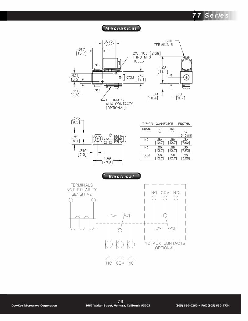
79DowKey Microwave Corporation 1667 Walter Street, Ventura, California 93003 (805) 650-0260 • FAX (805) 650-1734
77 Series
Mechanical
Electrical

78 Series Manual Multithrow Switch
These DowKey manually operated switches are constructed with coaxialswitching members rather than wafer switches. They are offered inSPDT, DPDT, SP3T, SP4T, and SP6T configurations, with the unusedports open (non-grounding). With RF power handling capabilities of 1 KW at 50 MHz and 60 dB isolation, the relay is ideal for use in lowfrequency, high power situations where signal integrity is a criticalparameter and switching time of less importance.
Typical applications for the 78 Series include:• Military/Commercial RF Communications• Laboratory Test Equipment• Video Viewing “Carrell” or Audition Room Source Selection• Patch Panels
Frequency VSWR Isolation Ins. Loss RF PowerMHz (max) dB (min) dB (max) Watts (CW)
50 1.10 60 0.03 1,000100 1.15 55 0.05 1,000225 1.25 45 0.10 600450 1.45 40 0.15 450
RF Characteristics
Connector SPDT DPDT SP3T SP4T SP6TType
N 78-0201 78-0701 78-0301 78-0401 78-0601BNC 78-0202 78-0702 78-0302 78-0402 78-0602UHF 78-0204 78-0704 78-0304 78-0404 78-0604
Connectors and Part Numbers
Operating Temperature:0ºC to +65ºC
Normal Weight:10.0 oz., (283g.)
Specifications :
DowKey® 78 Series Manual Multithrow Switch
80DowKey Microwave Corporation 1667 Walter Street, Ventura, California 93003 (805) 650-0260 • FAX (805) 650-1734

81DowKey Microwave Corporation 1667 Walter Street, Ventura, California 93003 (805) 650-0260 • FAX (805) 650-1734
78 Series
Mechanical
Electrical

79 Series Bypass Switches
The DowKey Microwave 79 Series bypass relays offer superior RF per-formance and an economical alternative to microwave transfer switchesin applications to 3 GHz.
Typical applications for the 79 Series include:• Amplifier Bypass• Power Monitor Circuit• Switch/Filter
Frequency VSWR Isolation Ins. Loss RF PowerGHz (max) dB (min) dB (max) Watts (CW)
0-1 1.10 80 0.05 500-2001-2 1.15 70 0.10 200-1002-3 1.25 60 0.20 100-50
RF Characteristics
Connectors and Part Numbers
Operating Voltage:(across temperature range)
12 Vdc (11-14 Vdc)28 Vdc (24-32 Vdc)
Coil Current (Nominal):12 Vdc 300 mA28 Vdc 258 mA
Operate Time:35 mS maximum
Operating Temperature:0ºC to +65ºC
Mechanical Life, Cycles:1 x 10⁶ minimum
Nominal Weight:7.0 oz., (200g.)
Specifications :
DowKey® 79 Series Bypass Switches
82DowKey Microwave Corporation 1667 Walter Street, Ventura, California 93003 (805) 650-0260 • FAX (805) 650-1734
Nominal Coil Connector Failsafe Voltage Type Standard
12 Vdc TNC 79-220328 Vdc TNC 79-2303

83DowKey Microwave Corporation 1667 Walter Street, Ventura, California 93003 (805) 650-0260 • FAX (805) 650-1734
79 Series
Mechanical
Electrical

116 Series SP4T Switch
The DowKey 116 Series are small multiple-position switches designedfor applications where one or more inputs or outputs are required to beconnected simultaneously. Each position has its own actuating solenoid,and each port may be grounded or non-grounded in the de-energizedstate. RF performance is excellent and remains stable to approximately3 GHz. Grounding the unused positions increases isolation.
Typical applications for the 116 Series include:• Military Communications Equipment• Multiple Video Monitor Switching• Multiple Test Monitor Switching
RF Characteristics
Nominal Coil Connector SP4T SP4TVoltage Type Grounding Non-Grounding
12 Vdc N 116-220101 116-22010228 Vdc N 116-230101 116-230102
12 Vdc BNC 116-220201 116-22020228 Vdc BNC 116-230201 116-230202
12 Vdc TNC 116-220301 116-22030228 Vdc TNC 116-230301 116-230302
Connectors and Part Numbers
Operating Voltage:(across temperature range)
12 Vdc (11-14 Vdc)28 Vdc (24-32 Vdc)
Coil Current (Nominal):12 Vdc 380 mA28 Vdc 96 mA
Operate Time:25 mS maximum
Operating Temperature:0ºC to +65ºC
Mechanical Life, Cycles:1 x 10⁶ minimum
Nominal Weight:12..0 oz., (340g.)
Specifications :
DowKey® 116 Series SP4T Switch
84DowKey Microwave Corporation 1667 Walter Street, Ventura, California 93003 (805) 650-0260 • FAX (805) 650-1734
Frequency VSWR Isolation Isolation Ins. Loss RF PowerGrounding Non-Grounding Watts
MHz (max) dB (min) dB (min) dB (max) (CW)
50 1.02 60 45 0.02 200100 1.02 55 40 0.03 200400 1.05 50 35 0.05 100
1,000 1.10 35 25 0.10 652,000 1.20 30 20 0.15 45

85DowKey Microwave Corporation 1667 Walter Street, Ventura, California 93003 (805) 650-0260 • FAX (805) 650-1734
116 Series
Mechanical
Electrical
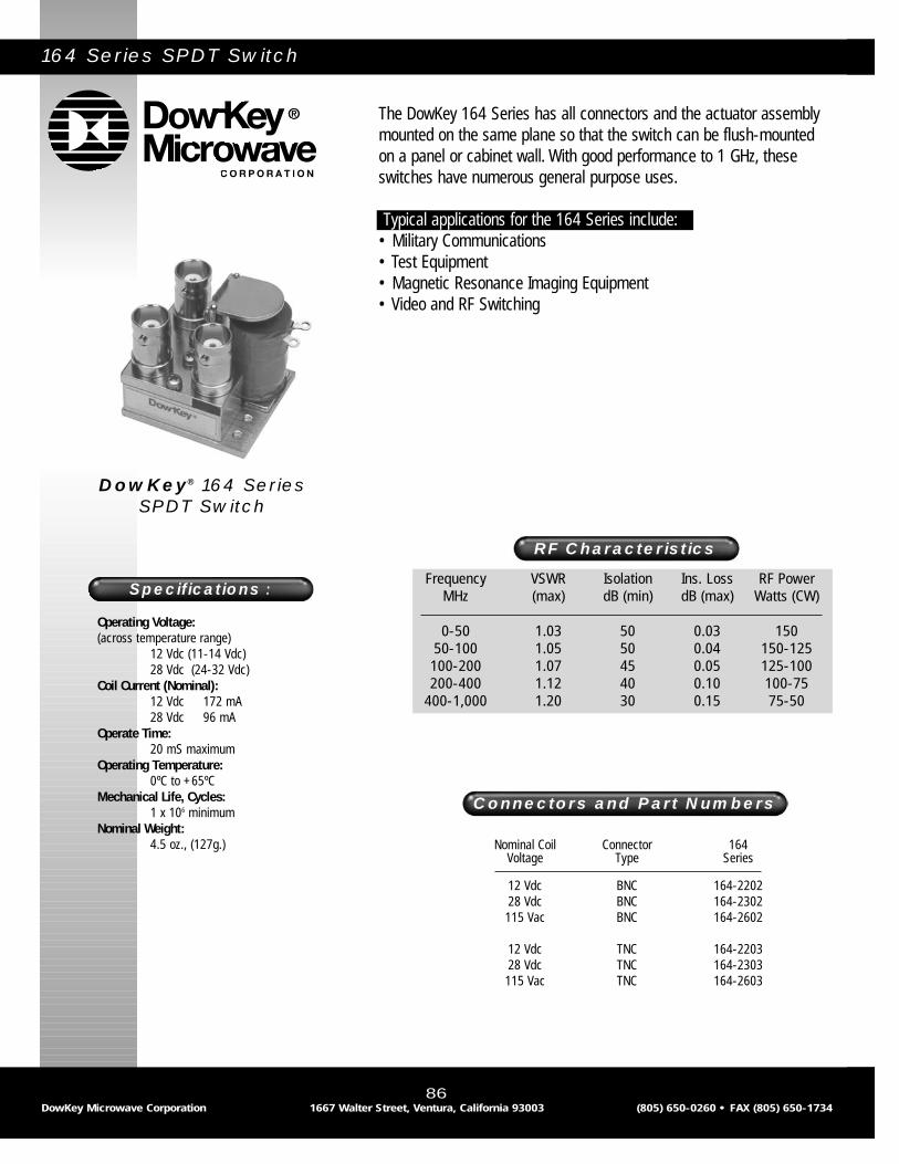
164 Series SPDT Switch
The DowKey 164 Series has all connectors and the actuator assemblymounted on the same plane so that the switch can be flush-mountedon a panel or cabinet wall. With good performance to 1 GHz, theseswitches have numerous general purpose uses.
Typical applications for the 164 Series include:• Military Communications • Test Equipment• Magnetic Resonance Imaging Equipment• Video and RF Switching
Frequency VSWR Isolation Ins. Loss RF PowerMHz (max) dB (min) dB (max) Watts (CW)
0-50 1.03 50 0.03 15050-100 1.05 50 0.04 150-125100-200 1.07 45 0.05 125-100200-400 1.12 40 0.10 100-75
400-1,000 1.20 30 0.15 75-50
RF Characteristics
Connectors and Part Numbers
Operating Voltage:(across temperature range)
12 Vdc (11-14 Vdc)28 Vdc (24-32 Vdc)
Coil Current (Nominal):12 Vdc 172 mA28 Vdc 96 mA
Operate Time:20 mS maximum
Operating Temperature:0ºC to +65ºC
Mechanical Life, Cycles:1 x 10⁶ minimum
Nominal Weight:4.5 oz., (127g.)
Specifications :
DowKey® 164 Series SPDT Switch
86DowKey Microwave Corporation 1667 Walter Street, Ventura, California 93003 (805) 650-0260 • FAX (805) 650-1734
Nominal Coil Connector 164Voltage Type Series
12 Vdc BNC 164-220228 Vdc BNC 164-2302115 Vac BNC 164-2602
12 Vdc TNC 164-220328 Vdc TNC 164-2303115 Vac TNC 164-2603

87DowKey Microwave Corporation 1667 Walter Street, Ventura, California 93003 (805) 650-0260 • FAX (805) 650-1734
164 Series
Mechanical
Electrical

167 Series Transfer Switches
The DowKey 167 Series transfer relay is designed for high power oper-ation, and is capable of handling up to 2 kilowatts at 30 MHZ. Theswitch has two coils which can be operated in parallel for break beforemake transfer. When the coils are operated separately, make beforebreak switching can be accomplished to either 2 or 4. All models havea DPDT set of auxiliary contacts.
Typical applications for the 167 Series include:• Switching Two Transmitters Between an Antenna and Dummy Load• Reversing the Feed Phase for Directional Antennas• High Power Amplifier Transfer and By-Pass Switching
Frequency VSWR Isolation Ins. Loss RF PowerMHz (max) dB (min) dB (max) Watts (max)*
0-25 1.05 45 0.04 2,00025-50 1.05 45 0.05 2,000-1,50050-100 1.08 40 0.06 1,500-1,000100-300 1.12 30 0.08 1,000-600300-500 1.15 25 0.10 600-450
500-1,000 1.50 20 0.50 400-300
RF Characteristics
Connectors and Part Numbers
Operating Voltage:(across temperature range)
12 Vdc (11-14 Vdc)28 Vdc (24-32 Vdc)
Coil Current (Nominal):12 Vdc 171 mA28 Vdc 96 mA
Operate Time:25 mS maximum
Operating Temperature:0ºC to +65ºC
Mechanical Life, Cycles:1 x 10⁶ minimum
Nominal Weight:12.0 oz., (340g.)
Specifications :
DowKey® 167 Series Transfer Switches
88DowKey Microwave Corporation 1667 Walter Street, Ventura, California 93003 (805) 650-0260 • FAX (805) 650-1734
Nominal Coil Connector PartVoltage Type Number
12 Vdc N 167-22014228 Vdc N 167-230142115 Vac N 167-260142
12 Vdc UHF** 167-22044228 Vdc UHF** 167-230442115 Vac UHF** 167-260442
** Not recommended for applications above 300 MHz.
*Power ratings shown are for cold switching. RF power must be removed prior to the switching cycle.
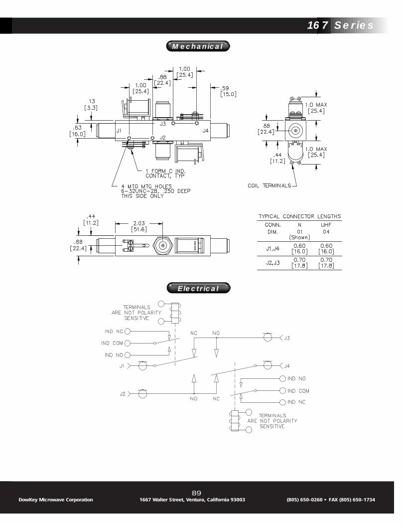
89DowKey Microwave Corporation 1667 Walter Street, Ventura, California 93003 (805) 650-0260 • FAX (805) 650-1734
Mechanical
Electrical
167 Series
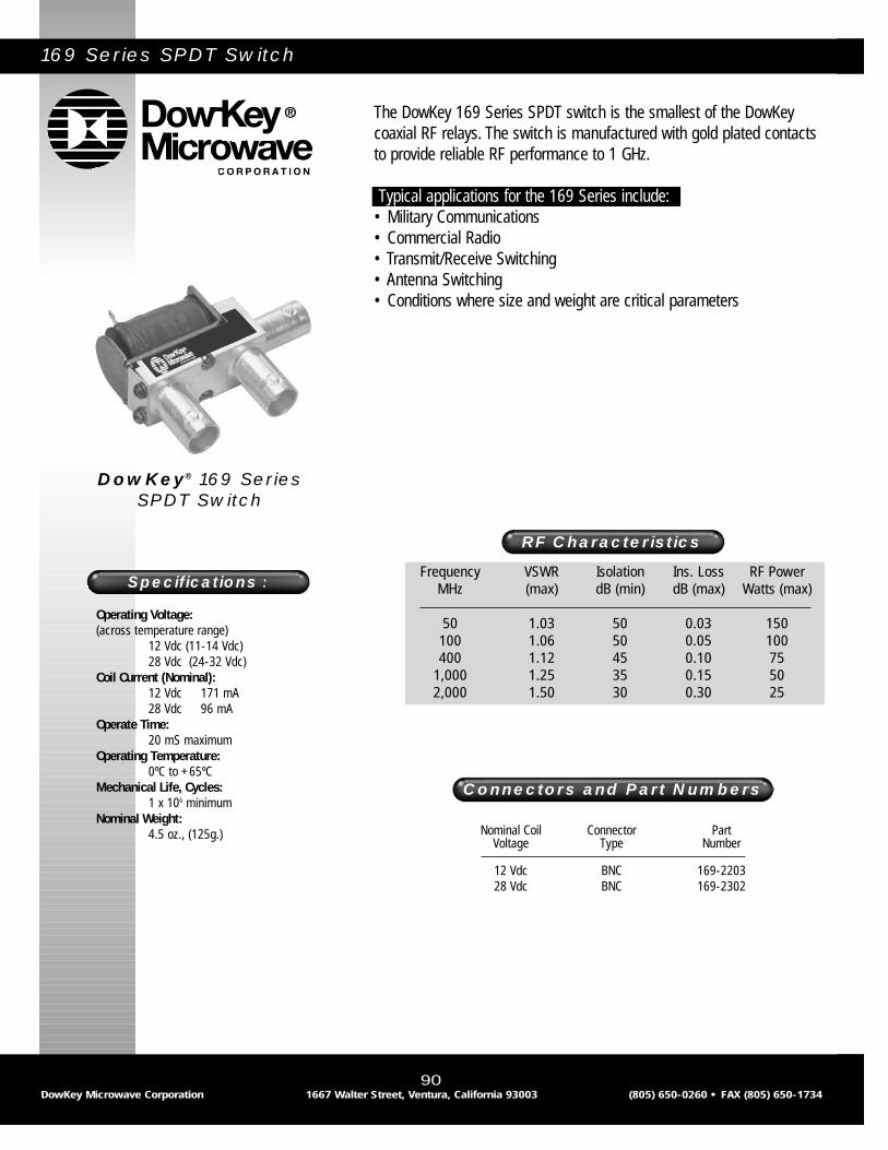
169 Series SPDT Switch
The DowKey 169 Series SPDT switch is the smallest of the DowKeycoaxial RF relays. The switch is manufactured with gold plated contactsto provide reliable RF performance to 1 GHz.
Typical applications for the 169 Series include:• Military Communications• Commercial Radio• Transmit/Receive Switching• Antenna Switching• Conditions where size and weight are critical parameters
Frequency VSWR Isolation Ins. Loss RF PowerMHz (max) dB (min) dB (max) Watts (max)
50 1.03 50 0.03 150100 1.06 50 0.05 100400 1.12 45 0.10 75
1,000 1.25 35 0.15 502,000 1.50 30 0.30 25
RF Characteristics
Connectors and Part Numbers
Operating Voltage:(across temperature range)
12 Vdc (11-14 Vdc)28 Vdc (24-32 Vdc)
Coil Current (Nominal):12 Vdc 171 mA28 Vdc 96 mA
Operate Time:20 mS maximum
Operating Temperature:0ºC to +65ºC
Mechanical Life, Cycles:1 x 10⁶ minimum
Nominal Weight:4.5 oz., (125g.)
Specifications :
DowKey® 169 Series SPDT Switch
90DowKey Microwave Corporation 1667 Walter Street, Ventura, California 93003 (805) 650-0260 • FAX (805) 650-1734
Nominal Coil Connector PartVoltage Type Number
12 Vdc BNC 169-220328 Vdc BNC 169-2302

91DowKey Microwave Corporation 1667 Walter Street, Ventura, California 93003 (805) 650-0260 • FAX (805) 650-1734
169 Series
Mechanical
Electrical

260 Series DPDT Switch 260B Series By-Pass Switch
The DowKey 260 Series is a standard DPDT switch with six connectors,allowing two of four straight-through paths from two inputs. The 260Bis identical in construction, except that there is an internal connectionbetween the N/C contacts, leaving only four connectors. The 260BSeries is widely used to insert or by-pass a circuit element (such as anamplifier or filter) in a transmission path between two normally con-nected elements. Both are available with a choice of actuator coils,connector options, and a pair of form “C” auxiliary contacts.
Typical applications for the 260 & 260B Series include:• Inserting a Linear Amplifier Between an Exciter and an Antenna• Filter, Attenuator, or Amplifier By-Pass Switching• Insert Filters or Attenuators in a Transmission Path• Dual Simultaneous Transmit/Receive or Antenna Switching
Frequency VSWR Isolation Ins. Loss RF PowerMHz (max) dB (min) dB (max) Watts (max)
0-50 1.05 40 0.04 1,00050-100 1.08 35 0.05 1,000100-400 1.15 25 0.10 1,000-500
400-1,000 1.20 18 0.15 500-350
RF Characteristics
Connectors and Part Numbers
Operating Voltage:(across temperature range)
12 Vdc (11-14 Vdc)26.5 Vdc (24-32 Vdc)
Coil Current (Nominal):12 Vdc 250 mA26.5 Vdc 110 mA
Operate Time:25 mS maximum
Operating Temperature:0ºC to +65ºC
Mechanical Life, Cycles:1 x 10⁶ minimum
Nominal Weight:12..0 oz., (340g.)
Specifications :
DowKey® 260 Series DPDT &260B Series
By-Pass Switch
92DowKey Microwave Corporation 1667 Walter Street, Ventura, California 93003 (805) 650-0260 • FAX (805) 650-1734
Nominal Coil Connector DPDT with 2 “C” By-Pass with 2 “C”Voltage Type Ind. Contacts Ind. Contacts
12 Vdc N 260-2201 260-220142 260B-2201 260B-22014226.5 Vdc N 260-2301 260-230142 260B-2301 260B-230142115 Vac N 260-2601 260-260142 260B-2601 260B-260142
12 Vdc BNC 260-2202 260-220242 260B-2202 260B-22024226.5 Vdc BNC 260-2302 260-220242 260B-2202 260B-220242115 Vac BNC 260-2602 260-220242 260B-2202 260B-220242
12 Vdc UHF* 260-2204 260-220442 260B-2204 260B-22044226.5 Vdc UHF* 260-2304 260-230442 260B-2304 260B-230442115 Vac UHF* 260-2604 260-260442 260B-2604 260B-260442
*Not recommended for applications above 300 MHz.

93DowKey Microwave Corporation 1667 Walter Street, Ventura, California 93003 (805) 650-0260 • FAX (805) 650-1734
260 Series
Mechanical
Electrical

310 Series SPDT High Power Vacuum Coaxial Switch
The DowKey 310 Series SPDT relays have high power handling capa-bility in a small package. The ability to handle up to 3 KW at low fre-quencies (up to 30 MHz) is achieved with vacuum-enclosed contacts,minimizing noise and losses. This rugged switch is capable of “hot”switching 1 KW at 30 MHz with the optional special Tungsten-Molybdenum contacts to avoid pitting when switched with RF powerapplied. (It should be noted that even with heavy-duty construction,hot-switching will reduce the typical operational life of 1,000,000cycles significantly - to approximately 10,000 cycles)
Typical applications for the 310 Series include:• High Power Transmitter Switching• Radar Pulse Forming Networks• Phased Array Antenna Systems• UHF/VHF Communications Systems• Magnetic Resonance Imaging Systems
Frequency VSWR Isolation Ins. Loss RF PowerMHz (max) dB (min) dB (max) Watts (CW)
30 1.05 35 0.07 3,00050 1.06 30 0.08 2,300100 1.08 25 0.09 2,000400 1.10 17 0.10 850
RF Characteristics
Connectors and Part Numbers
Operating Voltage:(across temperature range)
12 Vdc (11-14 Vdc)28 Vdc (24-32 Vdc)
Coil Current (Nominal):12 Vdc 150 mA28 Vdc 84 mA
Switching Time:8 mS maximum
Operating Temperature:-25ºC to +65ºC
Mechanical Life, Cycles:1 x 10⁶ minimum
Nominal Weight:9.0 oz., (260g.)
Specifications :
DowKey® 310 Series SPDT Switch
94DowKey Microwave Corporation 1667 Walter Street, Ventura, California 93003 (805) 650-0260 • FAX (805) 650-1734
Nominal Coil Connector PartVoltage Type Number
12 Vdc N 310-220128 Vdc N 310-2301115 Vac N 310-2601
12 Vdc HN 310-225128 Vdc HN 310-2351115 Vac HN 310-2651
12 Vdc SC 310-225328 Vdc SC 310-2353115 Vac SC 310-2653

95DowKey Microwave Corporation 1667 Walter Street, Ventura, California 93003 (805) 650-0260 • FAX (805) 650-1734
Mechanical
Electrical
310 Series

96DowKey Microwave Corporation 1667 Walter Street, Ventura, California 93003 (805) 650-0260 • FAX (805) 650-1734

DowKey Microwave Corporation 1667 Walter Street, Ventura, California 93003 (805) 650-0260 • FAX (805) 650-1734 97
DowKey/TRANSCO
Standard RF, Microwaveand Waveguide Switches
Transco
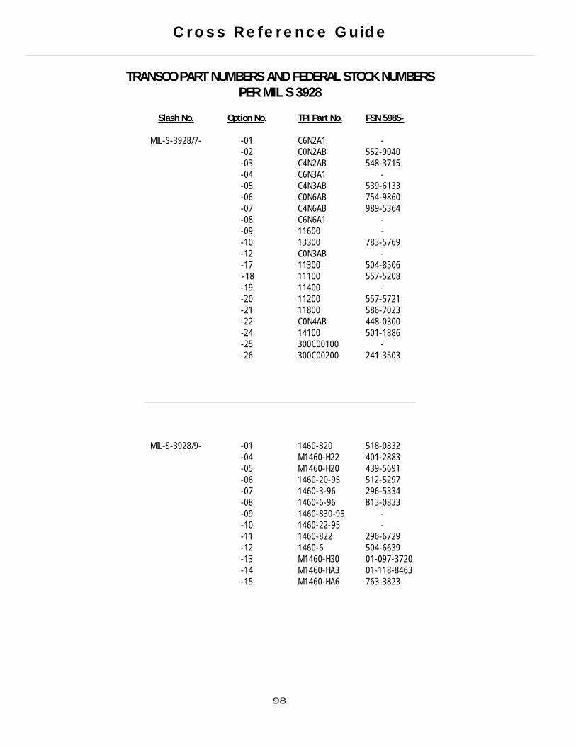
98
TRANSCO PART NUMBERS AND FEDERAL STOCK NUMBERS PER MIL S 3928
Slash No. Option No. TPI Part No. FSN 5985-
MIL-S-3928/7- -01 C6N2A1 --02 C0N2AB 552-9040-03 C4N2AB 548-3715-04 C6N3A1 --05 C4N3AB 539-6133-06 C0N6AB 754-9860-07 C4N6AB 989-5364-08 C6N6A1 --09 11600 --10 13300 783-5769-12 C0N3AB --17 11300 504-8506-18 11100 557-5208-19 11400 --20 11200 557-5721-21 11800 586-7023-22 C0N4AB 448-0300-24 14100 501-1886-25 300C00100 --26 300C00200 241-3503
MIL-S-3928/9- -01 1460-820 518-0832-04 M1460-H22 401-2883 -05 M1460-H20 439-5691 -06 1460-20-95 512-5297-07 1460-3-96 296-5334-08 1460-6-96 813-0833-09 1460-830-95 --10 1460-22-95 --11 1460-822 296-6729-12 1460-6 504-6639-13 M1460-H30 01-097-3720 -14 M1460-HA3 01-118-8463 -15 M1460-HA6 763-3823
Cross Reference Guide

Slash No.Option No.TPI Part No.FSN 5985
MIL-S-3928/10- -04 810C00100 272-7325123-8438*
-05 810C00200 433-675801-017-5236*
-06 810C05200 --07 315C05200 --08 310C00200 246-9414-09 810C00300 009-3691-0-09 810C00300 617-2436-10 300C00200 241-3503
MIL-S-3928/15- -01 919C70100 477-0060*433-8301
-06 900C70100 155-0122-07 909C7010 150-8559-08 909C70200 022-9059-09 919C72700 --10 919C70200 621-6997
-01 919C70100-8 01-043-0781 -07 909C70100-8 01-092-9506-08 909C70200-8 022-9059 -10 919C70200-8 00-150-8559
MIL-S-3928/17- -02 144C70100 01-106-0807*01-042-0669
144C70600 275-7009
MIL-S-3928/18- -01 146C70100 172-818701-086-0592*
-02 146C70600 005-2503-01 146C70100-8 -02 146C70600-8
MIL-S-3928/19- -01 700C70900 009-6619-02 710C70100 125-9895
-05 710C71400 -
-02 710C70100-8 01-106-3305 -05 710C71400-8 625-9681
MIL-S-3928/20- -01 820C31700 --03 810C30900 417-0532-04 910C90700 006-4308-06 900C31500 619-7145-07 81OC30100 248-2974
01-116-4495*-08 800C30200 325-6104
with diodes 01-021-4686
MIL-S-3928/21- -01 700C30200 139-174501-100-8860*
-02 310C30800 630-6674-03 300C30200 -
*Multiple federal stock numbers
99
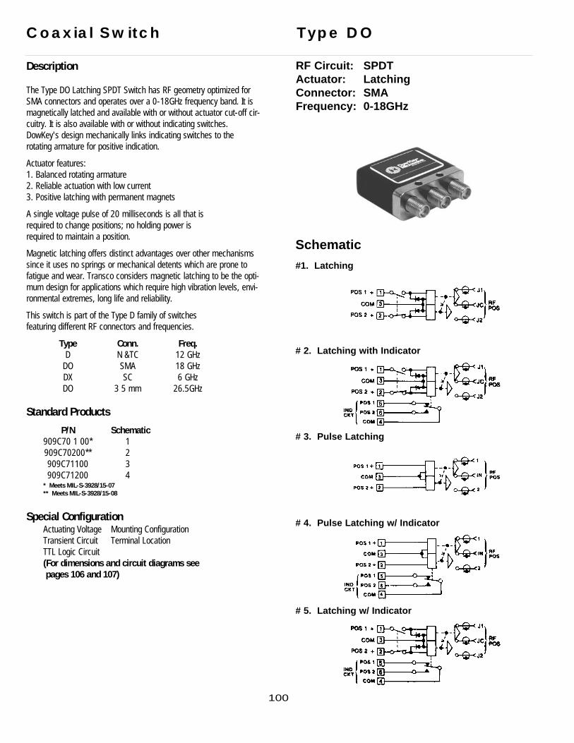
Description
The Type DO Latching SPDT Switch has RF geometry optimized forSMA connectors and operates over a 0-18GHz frequency band. It is magnetically latched and available with or without actuator cut-off cir-cuitry. It is also available with or without indicating switches.DowKey's design mechanically links indicating switches to the rotating armature for positive indication.
Actuator features:1. Balanced rotating armature2. Reliable actuation with low current3. Positive latching with permanent magnets
A single voltage pulse of 20 milliseconds is all that isrequired to change positions; no holding power isrequired to maintain a position.
Magnetic latching offers distinct advantages over other mechanismssince it uses no springs or mechanical detents which are prone tofatigue and wear. Transco considers magnetic latching to be the opti-mum design for applications which require high vibration levels, envi-ronmental extremes, long life and reliability.
This switch is part of the Type D family of switchesfeaturing different RF connectors and frequencies.
Type Conn. Freq.D N &TC 12 GHz
DO SMA 18 GHzDX SC 6 GHzDO 3 5 mm 26.5GHz
Standard Products
P/N Schematic909C70 1 00* 1909C70200** 2909C71100 3909C71200 4
* Meets MIL-S-3928/15-07** Meets MIL-S-3928/15-08
Special ConfigurationActuating Voltage Mounting ConfigurationTransient Circuit Terminal LocationTTL Logic Circuit (For dimensions and circuit diagrams see pages 106 and 107)
Coaxial Switch Type DO
RF Circuit: SPDTActuator: LatchingConnector: SMAFrequency: 0-18GHz
Schematic
#1. Latching
# 2. Latching with Indicator
# 3. Pulse Latching
# 4. Pulse Latching w/ Indicator
# 5. Latching w/ Indicator
100

SpecificationsTypical RF data of a production switch; computer printouts below:
Lower FrequencyAt 10MHz, typical values are: Isolation: 100dB VSWR: 1.05:1Insertion Loss: 0.05dBBecause of the inherently good RF performance at lower frequencies, this product line is not testedbelow 2GHz except upon request.
Voltage: 20 to 30VdcCoil Resistance: 310 + 10 Ohms @ 20°CCurrent: 95mA max @ 28Vdc and 20°CSwitching Time: 20 millisecondsRF Contacts: break-before-makeImpedance: 50 Ohms nominalTemperature: -55°C to 85°CVibration: 20g’s sine/randomLife: 1,000,000 cycles minWeight: 909C70100
909C71100909C70200909C71200
Dimensions
1.5 oz.
2.0 oz.
P/N A
909C70100909C71100 1.30905C91100
909C70200909C71200
1.50
101

102
Description
The type DO coaxial switch has RF geometry optimized for SMA con-nectors and operates over a 0-18GHz frequency band. It is also avail-able with or without indicators. DowKey’s design mechanically linksindicating switches to the rotating armature for positive indication.
Actuator features:1. Balanced rotating armature2. Low current required to develop the actuating torque
This design features a dual magnetic field for high efficiency and longlife reliability...also excellent shock/vibration characteristics.
This switch is part of the Type D family of switches featuring differentRF connectors and frequencies.
Type Conn. Freq.D N 12 GHz
DO SMA 18 GHzDX SC 6 GHz
Standard Products
P/N Schematic919C70100* 1919C70200** 2
* Meets MIL-S-3928/15-01** Meets MIL-S-3928/15-10
Special ConfigurationActuating Voltage Mounting ConfigurationTransient Circuit Terminal LocationTTL Logic Circuit (For dimensions and circuit diagrams see pages 106 and 107)
Coaxial Switch Type DO
RF Circuit: SPDTActuator: FailsafeConnector: SMAFrequency: 0-18GHz
Schematic# 1. Failsafe
# 2. Failsafe w/ Indicator
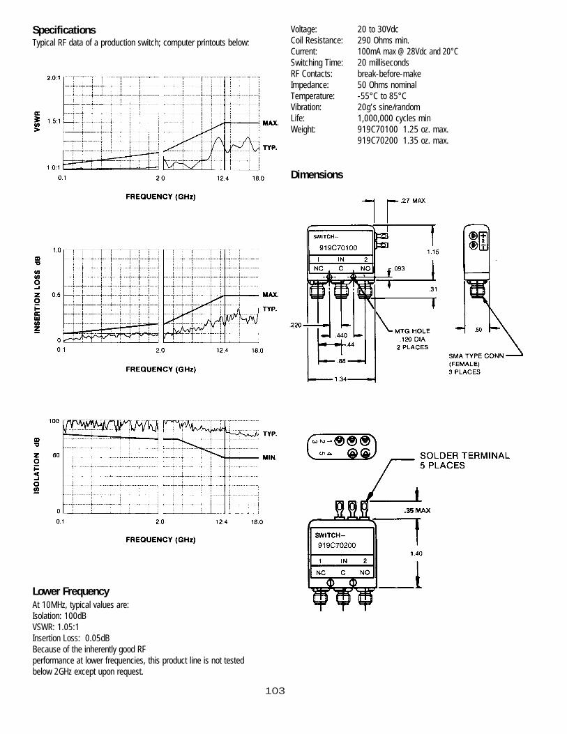
103
SpecificationsTypical RF data of a production switch; computer printouts below:
Lower FrequencyAt 10MHz, typical values are: Isolation: 100dB VSWR: 1.05:1Insertion Loss: 0.05dBBecause of the inherently good RF performance at lower frequencies, this product line is not testedbelow 2GHz except upon request.
Voltage: 20 to 30VdcCoil Resistance: 290 Ohms min.Current: 100mA max @ 28Vdc and 20°CSwitching Time: 20 millisecondsRF Contacts: break-before-makeImpedance: 50 Ohms nominalTemperature: -55°C to 85°CVibration: 20g’s sine/randomLife: 1,000,000 cycles minWeight: 919C70100 1.25 oz. max.
919C70200 1.35 oz. max.
Dimensions
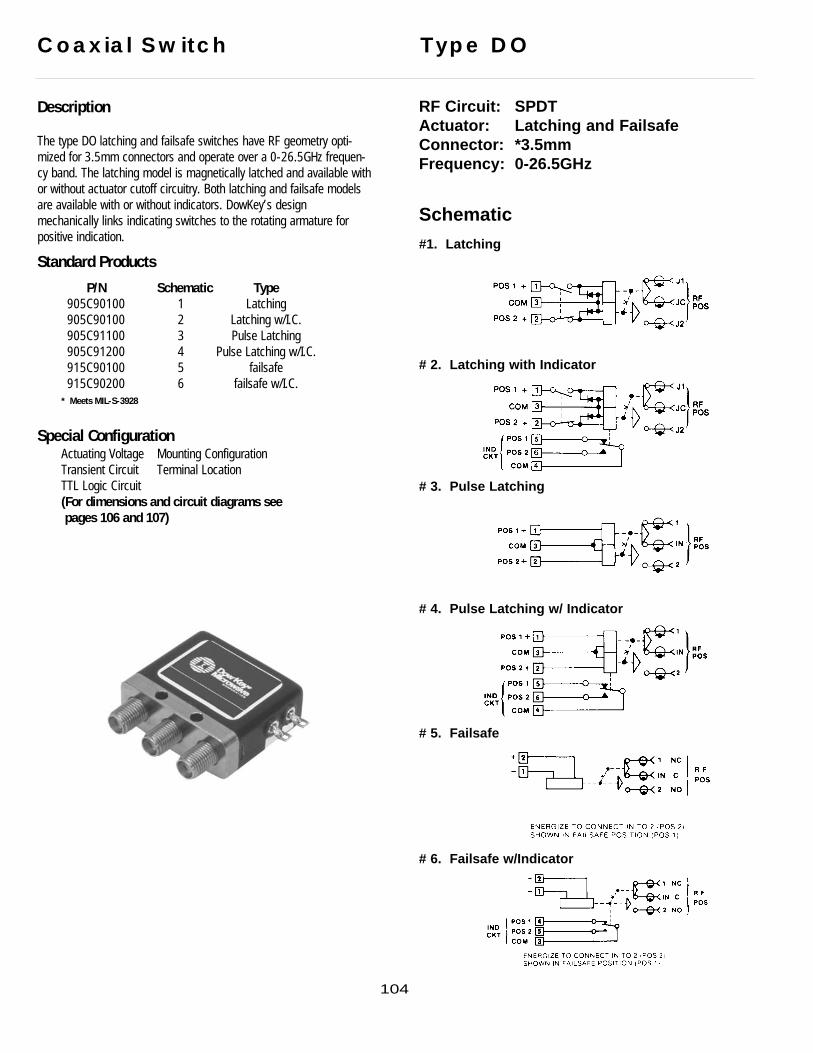
Description
The type DO latching and failsafe switches have RF geometry opti-mized for 3.5mm connectors and operate over a 0-26.5GHz frequen-cy band. The latching model is magnetically latched and available withor without actuator cutoff circuitry. Both latching and failsafe modelsare available with or without indicators. DowKey’s design mechanically links indicating switches to the rotating armature forpositive indication.
Standard Products
P/N Schematic Type905C90100 1 Latching905C90100 2 Latching w/I.C.905C91100 3 Pulse Latching905C91200 4 Pulse Latching w/I.C.915C90100 5 failsafe915C90200 6 failsafe w/I.C.
* Meets MIL-S-3928
Special ConfigurationActuating Voltage Mounting ConfigurationTransient Circuit Terminal LocationTTL Logic Circuit (For dimensions and circuit diagrams see pages 106 and 107)
Coaxial Switch Type DO
RF Circuit: SPDTActuator: Latching and FailsafeConnector: *3.5mmFrequency: 0-26.5GHz
Schematic
#1. Latching
# 2. Latching with Indicator
# 3. Pulse Latching
# 4. Pulse Latching w/ Indicator
# 5. Failsafe
# 6. Failsafe w/Indicator
104
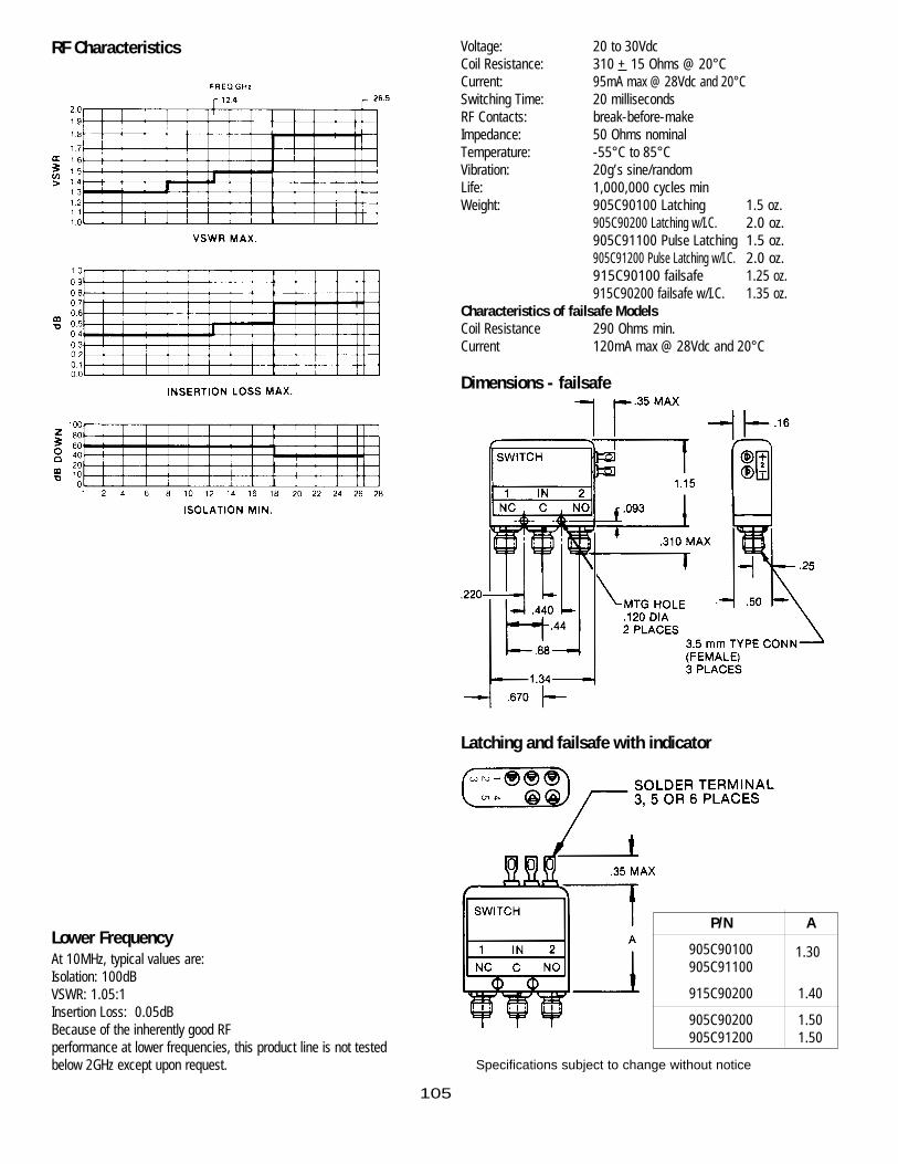
RF Characteristics
Lower FrequencyAt 10MHz, typical values are: Isolation: 100dB VSWR: 1.05:1Insertion Loss: 0.05dBBecause of the inherently good RF performance at lower frequencies, this product line is not testedbelow 2GHz except upon request.
Voltage: 20 to 30VdcCoil Resistance: 310 + 15 Ohms @ 20°CCurrent: 95mA max @ 28Vdc and 20°CSwitching Time: 20 millisecondsRF Contacts: break-before-makeImpedance: 50 Ohms nominalTemperature: -55°C to 85°CVibration: 20g’s sine/randomLife: 1,000,000 cycles minWeight: 905C90100 Latching 1.5 oz.
905C90200 Latching w/I.C. 2.0 oz.905C91100 Pulse Latching 1.5 oz.905C91200 Pulse Latching w/I.C. 2.0 oz.915C90100 failsafe 1.25 oz.915C90200 failsafe w/I.C. 1.35 oz.
Characteristics of failsafe ModelsCoil Resistance 290 Ohms min.Current 120mA max @ 28Vdc and 20°C
Dimensions - failsafe
Latching and failsafe with indicator
P/N A
905C90100905C91100
915C90200 1.40
905C90200 1.50905C91200 1.50
1.30
Specifications subject to change without notice
105

106
Schematic
TTL Logic Summary Data Sheet
909C70100-30 - 905C90100-30 909C70200-30 - 905C90200-30
909C71200-30 - 905C91200-30909C71100-30 - 905C91100-30
919C70100-30 - 915C90100-30 919C70200-30 - 915C90200-30

Dimensions
Logic Truth Table
Voltage28Vdc 20 to 30Vdc5Vdc 4.5 to 5.5VdcLogic 0 0 to 4VdcLogic 1 2.4 to 5.5Vdc pulse width 20ms at 20Vdc
Coil Current: 120mA max at 28Vdc, 20°CSwitching Time, Max: 20ms at 20Vdc
909C70200-30909C70100-30909C71100-30909C71200-30905C90100-30905C90200-30905C91100-30905C91200-30
Logic Truth Table
RF Logic SignalPath A BIn 1 1 0In 2 0 1
919C70100-30919C70200-30915C90100-30915C90200-30
Logic Truth Table
RF Logic SignalPath A In 1 0 In 2 1
TTL Logic Summary Data Sheet
107

Description
The Type D Latching SPDT Switch has RF geometry optimized for Nand TNC connectors and operates over a 0-12.4GHz frequency band.It is magnetically latched and available with or without an actuatorcut-off circuit. It is also available with or without indicating switches.DowKey’s design mechanically links indicating switches to the rotatingarmature for positive indication.
Actuator features:1. Balanced rotating armature2. Reliable actuation with low current3. Positive latching with permanent magnets
A single voltage pulse of 50 milliseconds is all that is required tochange positions; no holding power is required to maintain a position.
Magnetic latching offers distinct advantages over other mechanismssince it uses no springs or mechanical detents which are prone tofatigue and wear. DowKey considers magnetic latching to be the opti-mum design for applications which require high vibration levels, envi-ronmental extremes, long life and reliability.
This switch is part of the DowKey family of switches. Other types inthis family are referenced below.
Type Conn. Freq.DO SMA 18 GHzDX SC 6.5 GHz
Meets MIL-S-3928
Standard Products
P/N Conn. Schematic805C00100 N 1805C00200 N 2805C01100 N 3805C01200 N 4805C30100 TNC 1805C30200* TNC 2805C31100 TNC 3805C31200 TNC 4
Meets MIL-S-3928/20-08
Special ConfigurationDC-Power Plug TTL LogicTransient Circuit Terminal Location
Coaxial Switch Type D
RF Circuit: SPDTActuator: LatchingConnector: TNC & NFrequency: 0-12.4GHz
Schematic
#1. Latching
# 2. Latching with Indicator
# 3. Pulse Latching
# 4. Pulse Latching w/ Indicator
108
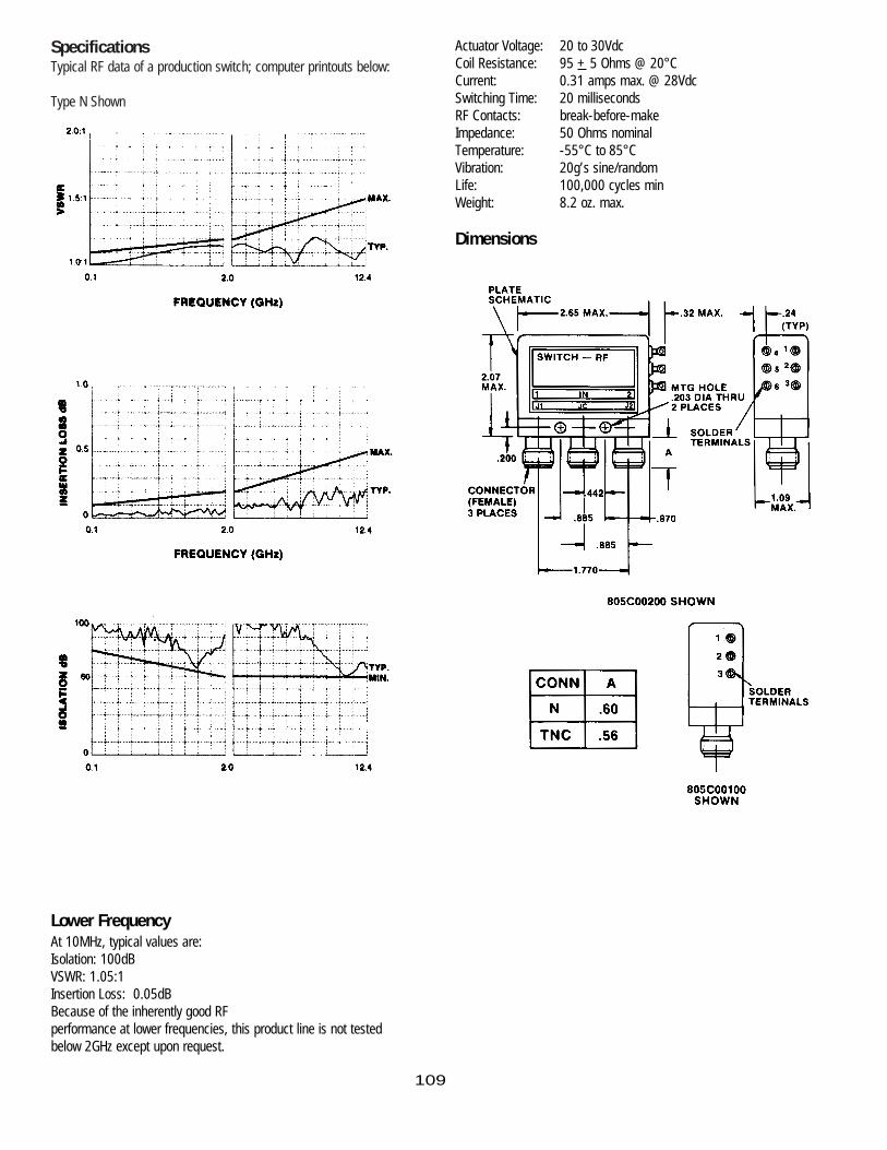
SpecificationsTypical RF data of a production switch; computer printouts below:
Type N Shown
Lower FrequencyAt 10MHz, typical values are: Isolation: 100dB VSWR: 1.05:1Insertion Loss: 0.05dBBecause of the inherently good RF performance at lower frequencies, this product line is not testedbelow 2GHz except upon request.
Actuator Voltage: 20 to 30VdcCoil Resistance: 95 + 5 Ohms @ 20°CCurrent: 0.31 amps max. @ 28VdcSwitching Time: 20 millisecondsRF Contacts: break-before-makeImpedance: 50 Ohms nominalTemperature: -55°C to 85°CVibration: 20g’s sine/randomLife: 100,000 cycles minWeight: 8.2 oz. max.
Dimensions
109

110
Description
The Type D Coaxial SPDT Switch has RF geometry optimized for TNCand N connectors and operates over a 0-12.4GHz frequency band. Itis also available with or without indicators. DowKey’s design mechani-cally links indicating switches to the rotating armature for positiveindication.
Actuator features:1. Balanced rotating armature2. Lower current required to develop the actuating torque.3. Dual holding power - permanent magnet plus electromagnet
This design features a dual magnetic field for high efficiency and longlife reliability...and excellent shock/vibration characteristics.
This switch is part of the DowKey family of switches. Other types inthis family are referenced below.
Type Conn. Freq.DO SMA 18 GHzDX SC 6.5 GHz
Standard Products
P/N Conn. Schematic810C00100 N 1810C00200 N 2810C30100 TNC 1810C30200 TNC 2
Meets MIL-S-3928/10-04 (810C00100)MIL-S-3928/10-05 (810C00200)
Special ConfigurationActuating Voltage TTL Logic CircuitTransient Circuit Terminal LocationMounting Configuration
Coaxial Switch Type D
RF Circuit: SPDTActuator: FailsafeConnector: TNC & NFrequency: 0-12.4GHz
Schematic
#1. Failsafe
# 2. Failsafe with Indicator Circuit

SpecificationsTypical RF data of a production switch; computer printouts below:
Type N Shown
Lower FrequencyAt 10MHz, typical values are: Isolation: 100dB VSWR: 1.05:1Insertion Loss: 0.05dBBecause of the inherently good RF performance at lower frequencies, this product line is not testedbelow 2GHz except upon request.
Actuator Voltage: 20 to 30VdcCoil Resistance: 190 + 10 Ohms @ 20°CCurrent: 160 amps max. @ 28Vdc and 20°CSwitching Time: 20 milliseconds max. RF to RFRF Contacts: break-before-makeImpedance: 50 Ohms nominalTemperature: -55°C to 85°CVibration: 20g’s sine/randomLife: 1,000,000 cycles minWeight: 8.2 oz. max.
Dimensions
111

Description
The Type DT Coaxial Switch has RF geometry optimized for TNC con-nectors and operates over a 0-12.4GHz frequency band. This typeswitch is in a smaller package than Type D and is available inLatching or failsafe models, with or without indicators.
Latching models use a magnetic latching actuator with cut-off circuit-ry. This switch draws current for approximately 30 milliseconds tochange position; no holding power is required to maintain a position.
The failsafe models feature dual holding power...a permanent magnetplus electromagnet for low current with high efficiency.
This switch is part of the DowKey family of switches. Other types inthis family are referenced below.
Type Conn. Freq.D N &TC 1 2.4 GHz
DO SMA 1 8 GHzDX SC 6.5 GHz
Standard Products
P/N Schematic900C30100 1900C30200 2910C30100 3910C30200 4
* Meets MIL-S-3928/15
Coaxial Switch Type DT
RF Circuit: SPDTActuator: Latching and failsafeConnector: TNCFrequency: 0-12.4GHz
Schematic
#1. Latching
# 2. Latching with Indicator
# 3. Failsafe
# 4. Failsafe w/ Indicator
112

Lower FrequencyAt 10MHz, typical values are: Isolation: 100dB VSWR: 1.05:1Insertion Loss: 0.05dBBecause of the inherently good RF performance at lower frequencies, this product line is not testedbelow 2GHz except upon request.
Voltage: 20 to 30VdcSwitching Time: 20 milliseconds max @ 28VdcRF Contacts: break-before-makeImpedance: 50 Ohms nominalTemperature: -55°C to 85°CVibration: 20g’s sine/randomLife: 100,000 cycles minWeight: 4 oz. max.
Latching Models900C30100 and 900C30200
Coil Resistance: 55 + 5 Ohms @ 20°CCurrent: 510mA max @ 28Vdc and 20°C
failsafe Models910C30100 and 910C30200
Coil Resistance: 115 + 5 Ohms @ 20°CCurrent: 280mA max @ 28Vdc and 20°C
Dimensions
Mating connectorto be 5/8” diameter
SpecificationsTypical RF data of a production switch; computer printouts below:
Type TNC Shown
113
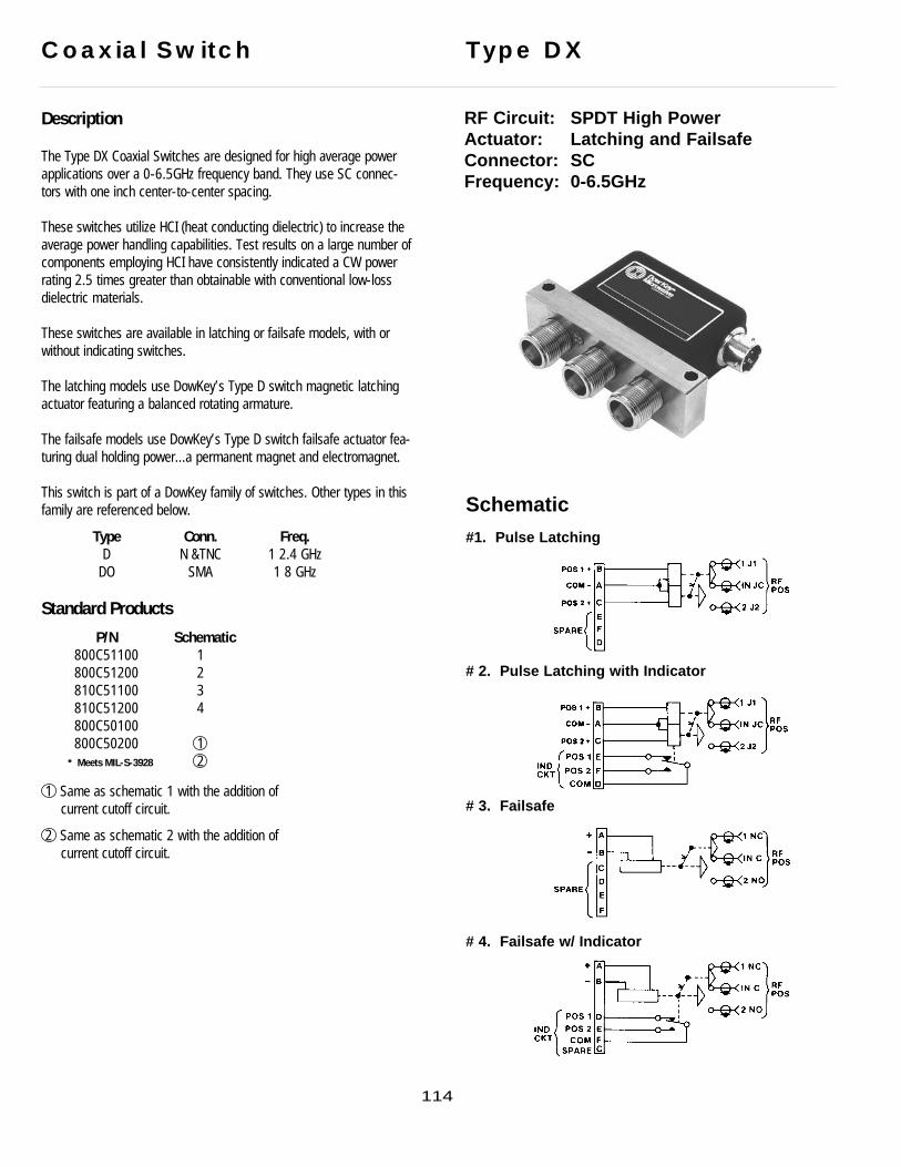
Description
The Type DX Coaxial Switches are designed for high average powerapplications over a 0-6.5GHz frequency band. They use SC connec-tors with one inch center-to-center spacing.
These switches utilize HCI (heat conducting dielectric) to increase theaverage power handling capabilities. Test results on a large number of components employing HCI have consistently indicated a CW powerrating 2.5 times greater than obtainable with conventional low-loss dielectric materials.
These switches are available in latching or failsafe models, with orwithout indicating switches.
The latching models use DowKey’s Type D switch magnetic latchingactuator featuring a balanced rotating armature.
The failsafe models use DowKey’s Type D switch failsafe actuator fea-turing dual holding power...a permanent magnet and electromagnet.
This switch is part of a DowKey family of switches. Other types in thisfamily are referenced below.
Type Conn. Freq.D N &TNC 1 2.4 GHz
DO SMA 1 8 GHz
Standard Products
P/N Schematic800C51100 1800C51200 2810C51100 3810C51200 4800C50100800C50200 1
* Meets MIL-S-3928 2
1 Same as schematic 1 with the addition of current cutoff circuit.
2 Same as schematic 2 with the addition of current cutoff circuit.
Coaxial Switch Type DX
RF Circuit: SPDT High PowerActuator: Latching and FailsafeConnector: SCFrequency: 0-6.5GHz
Schematic
#1. Pulse Latching
# 2. Pulse Latching with Indicator
# 3. Failsafe
# 4. Failsafe w/ Indicator
114

SpecificationsTypical RF data of a production switch; computer printouts below:
Lower FrequencyAt 10MHz, typical values are: Isolation: 100dB VSWR: 1.05:1Insertion Loss: 0.05dBBecause of the inherently good RF performance at lower frequencies, this product line is not testedbelow 2GHz except upon request.
Voltage: 20 to 30VdcRF Contacts: break-before-makeImpedance: 50 Ohms nominalTemperature: -55°C to 85°CVibration: 10g’s sine/randomLife: 100,000 cycles minWeight: 8.5 oz. max.
Latching Models800C51100 and 800C51200800C50100 and 800C50200
Coil Resistance: 95 + 5 Ohms @ 20°CCurrent: 320mA max @ 28Vdc and 20°CSwitching Time: 20mS max @ 28Vdc and 20°C
failsafe Models810C51100 and 810C51200
Coil Resistance: 310 + 5 Ohms @ 20°CCurrent: 280mA max @ 28Vdc and 20°CSwitching Time: 30mS max @ 28Vdc and 20°C
Dimensions
Ave
rage
Pow
er In
put -
Wat
ts
FREQUENCY (GHZ)1500 Watts Average At 1 GHz
RF POWER5000
4000
2000
1000800
600
400.2 .4 .6 .8 1.0 2.0 4.0 6.5
115

Description
The Type PD Switch has the RF contact operation of make-before-break for switching under RF power. The Type PD Switch is availablein latching or failsafe models with or without indicating switches.
MBB: Contacts arranged so the closing contacts make before interrupting the closed circuit. This type always has both circuits closed for an instant.
The MBB option offers an advantage in some high power switchingapplications because the maximum VSWR is limited to a value slightlyin excess of 2:1. The BBM type presents a momentary infinite VSWRduring switching.
The failsafe model features the same actuator design as the failsafeType D Switch.
This switch has been tested 63,000 cycles under the following condi-tions with no measurable effect on the performance specifications.
Power Frequency Cycles25 W CW 3350MHz 3,000150 W CW 250MHz 20,000
1087MHz 40,000
4KW pk., 5 W average.These are not maximum ratings. Please contact DowKey/Transcoregarding a switch to test in your system.
Standard Products
P/N Conn Schematic808C00100 N 1808C00200 N 2818C00100 N 3818C00200 N 4808C30100 TNC 1808C30200 TNC 2818C30100 TNC 3818C30200 TNC 4
* Meets MIL-S-3928
Coaxial Switch Type PD
RF Circuit: SPDT (MBB)Actuator: Latching and FailsafeConnector: TNC & NFrequency: 0-12.4GHz
Schematic
#1. Latching
# 2. Latching with Indicator
# 3. Failsafe
# 4. Failsafe w/ Indicator
Latching
Latching
failsafe
failsafe
116

SpecificationsTypical RF data of a production switch; computer printouts below:
Type N shown
Lower FrequencyAt 10MHz, typical values are: Isolation: 80dB VSWR: 1.05:1Insertion Loss: 0.05dBBecause of the inherently good RF performance at lower frequencies, this product line is not testedbelow 2GHz except upon request.
Voltage: 20 to 30VdcSwitching Time: 30 milliseconds max @ 28VdcRF Contacts: break-before-makeTime in MBB Pos 2mS approx.Impedance: 50 Ohms nominalTemperature: -55°C to 85°CVibration: 20g’s sine/randomLife: 100,000 cycles minWeight: 8 oz. max.
Latching Models808C00100 and 808C00200808C30100 and808C30200
Coil Resistance: 55 + 5 Ohms @ 20°CCurrent: .51 amp @ 28Vdc and 20°C
failsafe Models818C00100 and 818C00200818C30100 and 818C30200
Coil Resistance: 100 + 5 Ohms @ 20°CCurrent: .28 amp @ 28Vdc and 20°C
Dimensions
117

Description
The Type HO Coaxial Switch has RF geometry optimized for SMA connec-tors and operates over a 0-18GHz frequency band. It is magneticallylatched and available with or without an actuator cut-off circuit. It is alsoavailable with or without indicators. DowKey’s design mechanically linksindicating switches to the rotating armature for positive indication.
Actuator features:1. Balanced rotating armature2. Reliable actuation with low current3. Positive latching with permanent magnets4. Basic design concept qualified for space
applications.
A single voltage pulse of 20 milliseconds is all that is required to changepositions; no holding power is required to maintain a position.
Magnetic latching offers distinct advantages over other mechanisms sinceit uses no springs or mechanical detents which are prone to fatigue andwear. DowKey considers magnetic latching to be the optimum design forapplications which require high vibration levels, environmental extremes,long life and reliability.
This switch is part of a DowKey family of switches. Other types in thisfamily are referenced below.
Type Conn. Freq.H N 12.4GHzHT TNC 12.4GHzHX SC 6.5GHz
Standard Products
P/N Schematic700C70100 1700C70200 2700C71100 3700C71200 4
Meets MIL-S-3928
Special ConfigurationActuating Voltage TTL Logic CircuitTransient Circuit Terminal LocationPower Plug Mounting Configuration
Coaxial Switch Type HO
RF Circuit: TransferActuator: LatchingConnector: SMAFrequency: 0-18GHz
Schematic
#1. Latching
# 2. Latching with Indicator Circuit
# 3. Pulse Latching
# 4. Pulse Latching w/ Indicator Circuit
118

SpecificationsTypical RF data of a production switch; computer printouts below:
Lower FrequencyAt 10MHz, typical values are: Isolation: 100dB VSWR: 1.05:1Insertion Loss: 0.05dBBecause of the inherently good RF performance at lower frequencies, this product line is not testedbelow 2GHz except upon request.
Actuator Voltage: 20 to 30VdcCoil Resistance: 500 + 50 Ohms @ 20°CCurrent: 65 mA max. @ 28Vdc and 20°CSwitching Time: 20 milliseconds @
28Vdc and 20°CRF Contacts: break-before-makeImpedance: 50 Ohms nominalTemperature: -55°C to 85°CVibration: 20g’s sine/randomLife: 100,000 cycles minWeight: 3.5 oz. max.
Dimensions
119
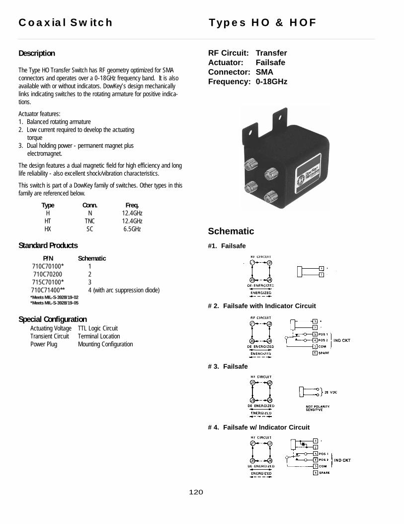
Description
The Type HO Transfer Switch has RF geometry optimized for SMAconnectors and operates over a 0-18GHz frequency band. It is alsoavailable with or without indicators. DowKey’s design mechanicallylinks indicating switches to the rotating armature for positive indica-tions.
Actuator features:1. Balanced rotating armature2. Low current required to develop the actuating
torque3. Dual holding power - permanent magnet plus
electromagnet.
The design features a dual magnetic field for high efficiency and longlife reliability - also excellent shock/vibration characteristics.
This switch is part of a DowKey family of switches. Other types in thisfamily are referenced below.
Type Conn. Freq.H N 12.4GHzHT TNC 12.4GHzHX SC 6.5GHz
Standard Products
P/N Schematic710C70100* 1710C70200 2715C70100* 3710C71400** 4 (with arc suppression diode)*Meets MIL-S-3928/19-02*Meets MIL-S-3928/19-05
Special ConfigurationActuating Voltage TTL Logic CircuitTransient Circuit Terminal LocationPower Plug Mounting Configuration
120
Coaxial Switch Types HO & HOF
RF Circuit: TransferActuator: FailsafeConnector: SMAFrequency: 0-18GHz
Schematic
#1. Failsafe
# 2. Failsafe with Indicator Circuit
# 3. Failsafe
# 4. Failsafe w/ Indicator Circuit

SpecificationsTypical RF data of a production switch; computer printouts below:
Type N Shown
Lower FrequencyAt 10MHz, typical values are: Isolation: 100dB VSWR: 1.05:1Insertion Loss: 0.05dBBecause of the inherently good RF performance at lower frequencies, this product line is not testedbelow 2GHz except upon request.
Actuator Voltage: 20 to 30VdcCoil Resistance: 250 + 25 Ohms @ 20°CCurrent: 120 mA max. @ 28Vdc and 20°CSwitching Time: 20 milliseconds @
28Vdc and 20°CRF Contacts: break-before-makeImpedance: 50 Ohms nominalTemperature: -55°C to 85°CVibration: 20g’s sine/randomLife: 100,000 cycles minWeight: 3.5 oz. max.
Dimensions
121

Description
The Type HO Coaxial Transfer Switches have RF geometry optimizedfor 3.5mm connectors and operate over a 0-26.5GHz frequency band.The latching model is magnetically latched and is available with orwithout actuator cutoff circuit. Both latching and failsafe models areavailable with or without indicators.
A single voltage pulse of 20 milliseconds is all that is required tochange positions. No holding power is required to maintain a position.
DowKey’s failsafe model design features a dual magnetic field for highefficiency and long life reliability - also excellent shock/vibration character-istics.
Standard Products
P/N Schematic Type705C90100 1 Latching705C90200 2 Latching w/I.C.705C91100 3 Pulse Latching705C91200 4 Pulse Latching w/I.C.745C90100 5 failsafe745C90200 6 failsafe w/I.C.
Meets MIL-S-3928
Special ConfigurationActuating Voltage Mounting ConfigurationTransient Circuit Terminal LocationTTL Logic Circuit Power Plug
Coaxial Switch Type HO
RF Circuit: TransferActuator: Latching and FailsafeConnector: 3.5mmFrequency: 0-26.5GHz
Schematic
#1. Latching
# 2. Latching with Indicator Circuit
# 3. Pulse Latching
# 4. Pulse Latching w/ Indicator Circuit
# 5. Failsafe
# 6. failsafe w/Indicator Circuit
122

SpecificationsMaximum RF performance of a production switch
RF Characteristics
Lower FrequencyAt 10MHz, typical values are: Isolation: 100dB VSWR: 1.05:1Insertion Loss: 0.05dBBecause of the inherently good RF performance at lower frequencies, this product line is not testedbelow 2GHz except upon request.
Voltage: 20 to 30VdcCoil Resistance: 500 + 50 Ohms @ 20°CCurrent: 65mA max @ 28Vdc and 20°CSwitching Time: 20 milliseconds @ 28Vdc and 20°CRF Contacts: break-before-makeImpedance: 50 Ohms nominalTemperature: -55°C to 85°CVibration: 20g’s sine/randomLife: 100,000 cycles minWeight: 3.5 oz.Characteristics of failsafe ModelsCoil Resistance 250 + 25 Ohms @ 20°CCurrent 120mA max @ 28Vdc and 20°C
Dimensions
123

Schematic
TTL Logic Summary Data Sheet
700C70100-30 - 705C90100-30 700C70200-30 - 705C90200-30
700C71200-30 - 705C91200-30700C71100-30 - 705C91100-30
710C70100-30 - 745C90100-30 710C70200-30 - 745C90200-30
124

Dimensions
Logic Truth Table
Voltage28Vdc 20 to 30Vdc5Vdc 4.5 to 5.5VdcLogic 0 0 to .4VdcLogic 1 2.4 to 5.5Vdc pulse width 20ms at 20Vdc MIN
Switching Time, Max: 20ms at 20Vdc
700C70100-30700C70200-30700C71100-30700C71200-30705C90100-30705C90200-30705C91100-30705C91200-30
Logic Truth Table
RF Logic SignalPosition A BPos 1 1 0Pos 2 0 1
710C70100-30710C70200-30745C90100-30745C90200-30
Logic Truth Table
RF Logic SignalPosition A Pos 1 0 Pos 2 1
TTL Logic Summary Data Sheet
125

Description
The Type H Latching Transfer Switch has RF geometry optimized forTNC and N connectors and operates over a 0-12.4GHz frequencyband. The actuator is a magnetic latching type utilizing a current cut-off circuit. It is also available with or without indicatingswitches. DowKey’s design mechanically links indicating switches tothe rotating armature for positive indication.
Actuator features:1. Symmetrical armature2. Positive latching with permanent magnets.
Magnetic latching offers distinct advantages over other mechanismssince it uses no springs or mechanical detents which are prone tofatigue and wear. DowKey considers magnetic latching to be the opti-mum design for applications which require high vibration levels, envi-ronmental extremes, long life and reliability.
Type Conn. Freq.HO SMA 18GHzHT TNC 12.4GHzHX SC 6.5GHz
Standard Products
Pin Conn Schematic300C00100 N 1300C00200* N 2300C30100 TNC 1
300C30200** TNC 2
* Meets MIL-S-3928/10-10** Meets MIL-S-3928/21-03
Special ConfigurationActuating Voltage Mounting ConfigurationTTL Logic Circuit Terminal Location
Coaxial Switch Type H
RF Circuit: TransferActuator: LatchingConnector: N & TNCFrequency: 0-12.4GHz
Schematic# 1. Latching
# 2. Latching w/ Indicator Circuit
126

SpecificationsTypical RF data of a production switch; computer printouts below:
Lower FrequencyAt 10MHz, typical values are: Isolation: 100dB VSWR: 1.05:1Insertion Loss: 0.05dBBecause of the inherently good RF performance at lower frequencies, this product line is not testedbelow 2GHz except upon request.
Voltage: 20 to 30VdcCoil Resistance: 45 + 5 Ohms @ 20°CCurrent: .65 amp max @ 28Vdc and 20°CSwitching Time: 20 milliseconds max RF to RFRF Contacts: break-before-makeImpedance: 50 Ohms nominalTemperature: -55°C to 85°CVibration: 20g’s sine/randomLife: 100,000 cycles minWeight: 12 oz.
Dimensions
127

Description
The Type H failsafe Transfer switch has RF geometry optimized forType N and TNC connectors and operates over a 0-12.4GHz frequen-cy band. It is available with or without indicating switches. DowKey’sdesign mechanically links indicating switches to the rotating armaturefor positive indication.
A proven failsafe actuator is utilized to provide reliable performance inapplications where the simplicity of failsafe operation is desired.
This switch is part of a DowKey family of switches. Other types in thisfamily are referenced below.
Type Conn. Freq.HO SMA 18GHzHT TNC 12.4GHzHX SC 6.5GHz
Standard Products
P/N Conn Schematic310C00100 N 1310C00200* N 2310C30100 TNC 1310C30200 TNC 2
Other ProductsP/N Schematic
310C30800** 3with solder terminals*Meets MIL-S-3928/10-08** Meets Mil-S-3928/21-02
Special ConfigurationActuating Voltage TTL Logic CircuitTransient Current Terminal LocationMounting Configuration
Coaxial Switch Type H
RF Circuit: TransferActuator: FailsafeConnector: N & TNCFrequency: 0-12.4GHz
Schematic
#1. Failsafe
# 2. Failsafe with Indicator Circuit
# 3. Failsafe with Indicator and Solder Terminal
128

SpecificationsTypical RF data of a production switch; computer printouts below:
Lower FrequencyAt 10MHz, typical values are: Isolation: 90dB VSWR: 1.05:1Insertion Loss: 0.05dBBecause of the inherently good RF performance at lower frequencies, this product line is not testedbelow 2GHz except upon request.
Actuator Voltage: 20 to 30VdcCurrent: 1.0 amp max. @ 28Vdc
and 20°CSwitching Time: 20 milliseconds max RF to RFRF Contacts: break-before-makeImpedance: 50 Ohms nominalTemperature: -55°C to 85°CVibration: 20g’s sine/randomLife: 100,000 cycles minWeight: 12 oz. max.
Dimensions
129

Description
The Type HT Coaxial Switch has RF geometry optimized for TNC con-nectors and operates over a 0-12.4GHz frequency band. The modelHT is available in latching or failsafe models. It offers TNC connectorsin the smallest possible package. Both models are available with orwithout indicators. DowKey’s design mechanically links indicatingswitches to the rotating armature for positive indications.
The latching models use a magnetic latching actuator featuring a bal-anced rotating armature and a current cut-off circuit. Current isrequired for only 30 milliseconds to change position; no holding poweris required.
The failsafe models feature dual holding power...a permanent magnetplus electromagnet for low current with high efficiency.
This switch is part of the DowKey family of switches. Other types inthis family are referenced below.
Type Conn. Freq.H N 12.4 GHz
HO SMA 18 GHzHX SC 6.5 GHz
Standard Products
P/N Schematic700C30100 1700C30200* 2710C30100 3710C30200 4
* Meets MIL-S-3928/21-01
Special ConfigurationActuating Voltage TTL Logic CircuitTerminal Location Mounting Configuration
Coaxial Switch Type HT
RF Circuit: TransferActuator: Latching and FailsafeConnector: TNCFrequency: 0-12.4GHz
Schematic
#1. Latching
# 2. Latching with Indicator Circuit
# 3. Failsafe
# 4. Failsafe w/ Indicator Circuit
130

SpecificationsTypical RF data of a production switch; computer printouts below:
Lower FrequencyAt 10MHz, typical values are: Isolation: 100dB VSWR: 1.05:1Insertion Loss: 0.05dBBecause of the inherently good RF performance at lower frequencies, this product line is not testedbelow 2GHz except upon request.
Failsafe ModelsCoil Resistance: 250 + 25 Ohms @ 20°CCurrent: 120mA @ 28Vdc and 20°C
Latching ModelsCoil Resistance: 500 + 50 Ohms @ 20°CCurrent: 65mA @ 28Vdc and 20°CVoltage: 20 to 30VdcSwitching Time: 20 milliseconds max RF to RFRF Contacts: break-before-makeImpedance: 50 Ohms nominalTemperature: -55°C to 85°CVibration: 20g’s sine/randomLife: 100,000 cycles minWeight: 3.5 oz. max.
Dimensions
Mating connectorto be 5/8” diameter
131
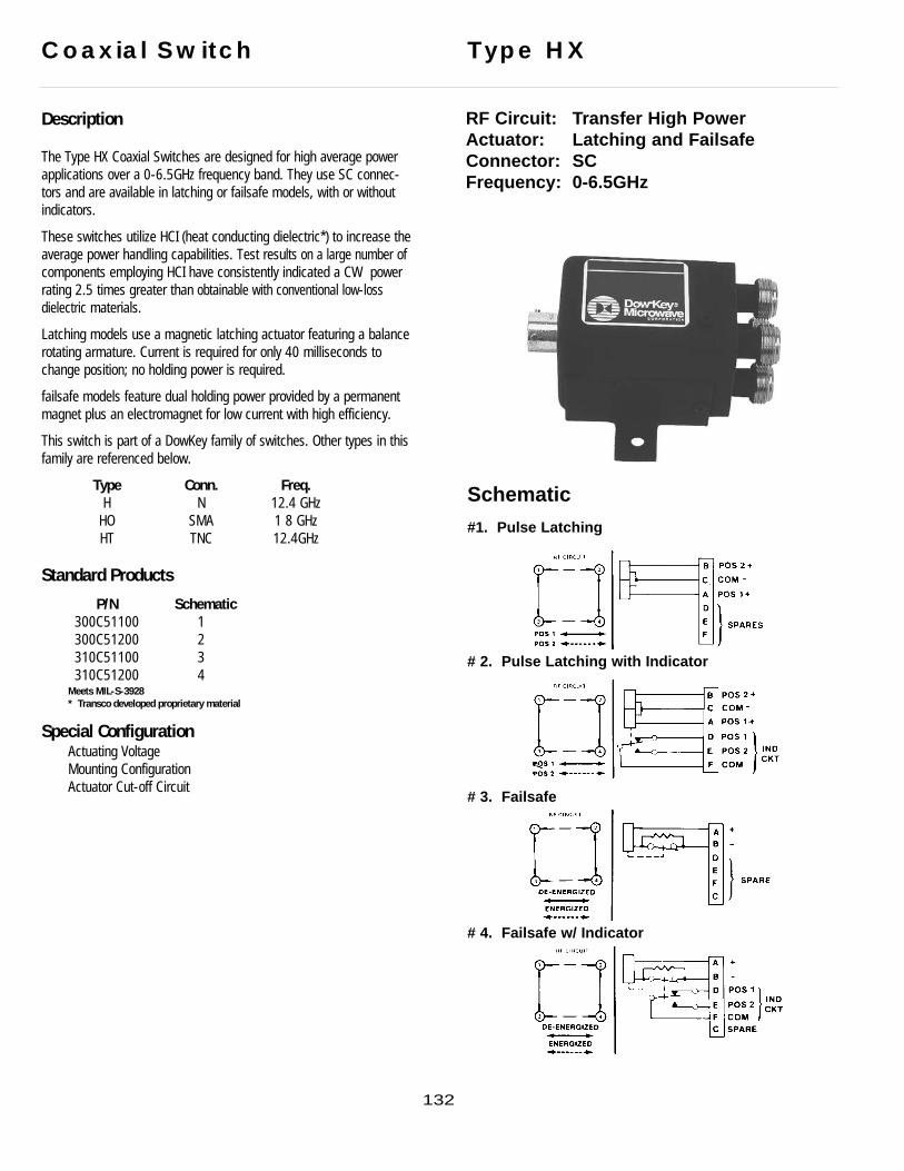
Description
The Type HX Coaxial Switches are designed for high average powerapplications over a 0-6.5GHz frequency band. They use SC connec-tors and are available in latching or failsafe models, with or withoutindicators.
These switches utilize HCI (heat conducting dielectric*) to increase theaverage power handling capabilities. Test results on a large number ofcomponents employing HCI have consistently indicated a CW powerrating 2.5 times greater than obtainable with conventional low-lossdielectric materials.
Latching models use a magnetic latching actuator featuring a balancerotating armature. Current is required for only 40 milliseconds tochange position; no holding power is required.
failsafe models feature dual holding power provided by a permanentmagnet plus an electromagnet for low current with high efficiency.
This switch is part of a DowKey family of switches. Other types in thisfamily are referenced below.
Type Conn. Freq.H N 12.4 GHz
HO SMA 1 8 GHzHT TNC 12.4GHz
Standard Products
P/N Schematic300C51100 1300C51200 2310C51100 3310C51200 4
Meets MIL-S-3928* Transco developed proprietary material
Special ConfigurationActuating VoltageMounting ConfigurationActuator Cut-off Circuit
Coaxial Switch Type HX
RF Circuit: Transfer High PowerActuator: Latching and FailsafeConnector: SCFrequency: 0-6.5GHz
Schematic
#1. Pulse Latching
# 2. Pulse Latching with Indicator
# 3. Failsafe
# 4. Failsafe w/ Indicator
132

SpecificationsTypical RF data of a production switch; computer printouts below:
Lower FrequencyAt 10MHz, typical values are: Isolation: 100dB VSWR: 1.05:1Insertion Loss: 0.05dBBecause of the inherently good RF performance at lower frequencies, this product line is not testedbelow 2GHz except upon request.
Voltage: 22 to 30VdcSwitching Time: 20 milliseconds max @ 28VdcRF Contacts: break-before-makeImpedance: 50 Ohms nominalTemperature: -55°C to 85°CVibration: 10g’s sine/randomLife: 100,000 cycles minWeight: 12.5 oz. max.
Latching Models300C51100 and 300C51200
Current: .65 amp @ 28Vdc and 20°C
failsafe Models310C51100 and 310C51200
Current Pull-in: 1.1 amp max @ 28Vdc and 20°CCurrent Holding: 270 mA max @ 28Vdc and 20°C
Dimensions
Ave
rage
Pow
er In
put -
Wat
ts
FREQUENCY (GHZ)1500 Watts Average At 1 GHz
RF POWER5000
4000
2000
1000800
600
400.2 .4 .6 .8 1.0 2.0 4.0 6.5
133

Description
The Type MO SP3T to SP6T switch utilizes selective linear actuatorsfor each position. RF geometry is optimized for SMA connectors andoperates over a 0-18GHz frequency band. Individual solenoids meanfaster switching time...no waiting for the switch to sequence througha number of positions before stopping at the selected position.Separate “selective” solenoids provide positive action and a low actu-ator current requirement.
This switch is part of a DowKey family of switches. Other types in thisfamily are referenced below:
Type Conn. Freq.M N &TNC 12.4 GHzMX SC 6.5 GHzML N &TNC 12.4GHz
Standard Products
P/N Schematic143C70600 1144C70600 2145C70600 3146C70600* 4146C70600-30 5 TTL Logic
* Meets MIL-S-3928/18-02
Special ConfigurationActuating Voltage Mounting ConfigurationTransient Circuit Terminal LocationTTL Logic Circuit (For dimensions and circuit diagrams see page 144)
Coaxial Switch Type MO
RF Circuit: SP3T to SP6TActuator: *Selective with Solder T erminalsConnector: SMAFrequency: 0-18GHz
Schematic
#1. 3 POS # 2. 4 POS
# 3. 5 POS # 4. 6 POS
# 5. 146C70600-30
134
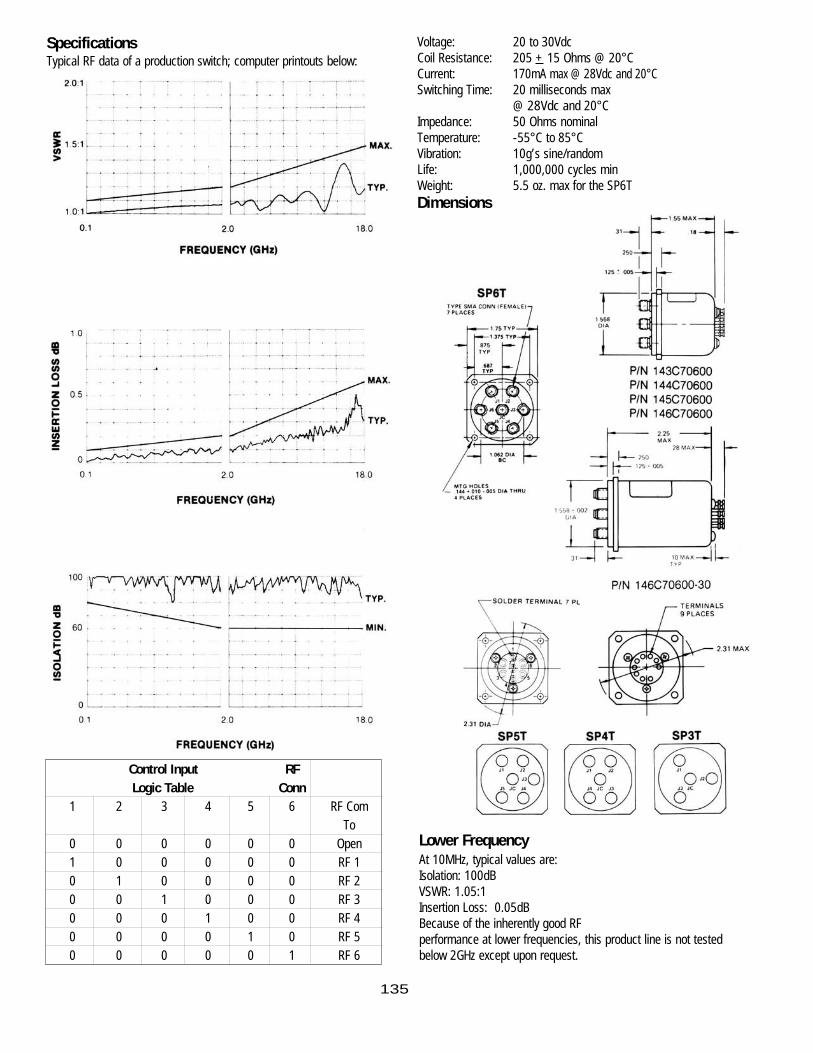
Control Input RF Logic Table Conn
1 2 3 4 5 6 RF ComTo
0 0 0 0 0 0 Open1 0 0 0 0 0 RF 10 1 0 0 0 0 RF 20 0 1 0 0 0 RF 30 0 0 1 0 0 RF 40 0 0 0 1 0 RF 50 0 0 0 0 1 RF 6
SpecificationsTypical RF data of a production switch; computer printouts below:
Lower FrequencyAt 10MHz, typical values are: Isolation: 100dB VSWR: 1.05:1Insertion Loss: 0.05dBBecause of the inherently good RF performance at lower frequencies, this product line is not testedbelow 2GHz except upon request.
Voltage: 20 to 30VdcCoil Resistance: 205 + 15 Ohms @ 20°CCurrent: 170mA max @ 28Vdc and 20°CSwitching Time: 20 milliseconds max
@ 28Vdc and 20°CImpedance: 50 Ohms nominalTemperature: -55°C to 85°CVibration: 10g’s sine/randomLife: 1,000,000 cycles minWeight: 5.5 oz. max for the SP6T Dimensions
135

136
Coaxial Switch Type MOI
RF Circuit: SP3T to SP6T (w/ Indicator)Actuator: *SelectiveConnector: SMAFrequency: 0-18GHz
Schematic
#1. 3 POS # 2. 4 POS
# 3. 5 POS # 4. 6 POS
Description
The Type MOI SP3T to SP6T switch utilizes selected linear actuatorsfor each position. RF geometry is optimized for SMA connectors andoperates over a 0-18GHz frequency band. Individual solenoids meanfaster switching time...no waiting for the switch to sequence througha number of positions before stopping at the selected position.Separate “selective” solenoids provide positive action and a low actu-ator current requirement. These switches are supplied with indicatingswitches that are mechanically linked to each solenoid for positiveposition indication.
This switch is part of a DowKey family of switches. Other types in thisfamily are referenced below
Type Conn. Freq.M N &TNC 12.4 GHzMX SC 6.5 GHzML N &TNC 12.4GHzMO SMA 18GHz
Standard Products
P/N Schematic143C71300 1144C71300 2145C71300 3146C71300 4
Meets MIL-S-3928
Special ConfigurationActuating Voltage TTL Logic Circuit Transient Circuit Power Connector
* Solenoid for each RF position

SpecificationsTypical RF data of a production switch; computer printouts below:
Lower FrequencyAt 10MHz, typical values are: Isolation: 100dB VSWR: 1.05:1Insertion Loss: 0.05dBBecause of the inherently good RF performance at lower frequencies, this product line is not testedbelow 2GHz except upon request.
Voltage: 24 to 30VdcCoil Resistance: 205 + 15 Ohms @ 20°CCurrent: 170mA max @ 28Vdc and 20°CSwitching Time: 20 milliseconds
@ 28Vdc and 20°CImpedance: 50 Ohms nominalTemperature: -55°C to 85°CVibration: 20g’s sine/randomLife: 1,000,000 cycles minWeight: 5.5 oz. max for the SP6T
Dimensions
137

Description
The Type MO SP3T to SP6T switch utilizes selected linear actuatorsfor each position. RF geometry is optimized for 3.5mm connectorsand operates over a 0-26.5GHz frequency band. Individual solenoidsmean faster switching time...no waiting for the switch to sequencethrough a number of positions before stopping at the selected posi-tion. Separate “selective” solenoids provide positive action and a lowactuator current requirement.
Standard Products
P/N Schematic Type153C90600 1 Selective 3 pos.154C90600 2 Selective 4 pos.155C90600 3 Selective 5 pos.156C90600 4 Selective 6 pos.
Meets MIL-S-3928
Special ConfigurationActuating Voltage Transient CircuitTTL Logic Circuit
Coaxial Switch Type MO
RF Circuit: SP3T to SP6TActuator: Selective with Solder T erminals*Connector: 3.5mm**Frequency: 0-26.5GHz
Schematic
#1. 3 POS # 2. 4 POS
# 3. 5 POS # 4. 6 POS
138

Specifications* Solenoid for each RF position** Mates with SMA
RF Characteristics
Lower FrequencyAt 10MHz, typical values are: Isolation: 100dB VSWR: 1.05:1Insertion Loss: 0.05dBBecause of the inherently good RF performance at lower frequencies, this product line is not testedbelow 2GHz except upon request.
Voltage: 20 to 30VdcCoil Resistance: 205 + 15 Ohms @ 20°CCurrent: 170mA max @ 28Vdc and 20°CSwitching Time: 20 milliseconds
@ 28Vdc and 20°CImpedance: 50 Ohms nominalTemperature: -55°C to 85°CVibration: 10g’s sine/randomLife: 1,000,000 cycles minWeight: 5.5 oz. max for the SP6T
Dimensions
139
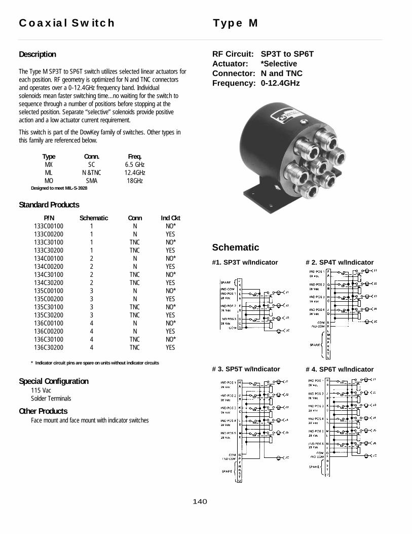
Description
The Type M SP3T to SP6T switch utilizes selected linear actuators foreach position. RF geometry is optimized for N and TNC connectorsand operates over a 0-12.4GHz frequency band. Individual solenoids mean faster switching time...no waiting for the switch tosequence through a number of positions before stopping at theselected position. Separate “selective” solenoids provide positiveaction and a low actuator current requirement.
This switch is part of the DowKey family of switches. Other types inthis family are referenced below.
Type Conn. Freq.MX SC 6.5 GHzML N &TNC 12.4GHzMO SMA 18GHz
Designed to meet MIL-S-3928
Standard Products
P/N Schematic Conn Ind Ckt133C00100 1 N NO*133C00200 1 N YES133C30100 1 TNC NO*133C30200 1 TNC YES134C00100 2 N NO*134C00200 2 N YES134C30100 2 TNC NO*134C30200 2 TNC YES135C00100 3 N NO*135C00200 3 N YES135C30100 3 TNC NO*135C30200 3 TNC YES136C00100 4 N NO*136C00200 4 N YES136C30100 4 TNC NO*136C30200 4 TNC YES
* Indicator circuit pins are spare on units without indicator circuits
Special Configuration115 VacSolder Terminals
Other ProductsFace mount and face mount with indicator switches
Coaxial Switch Type M
RF Circuit: SP3T to SP6TActuator: *Selective Connector: N and TNCFrequency: 0-12.4GHz
Schematic
#1. SP3T w/Indicator # 2. SP4T w/Indicator
# 3. SP5T w/Indicator # 4. SP6T w/Indicator
140
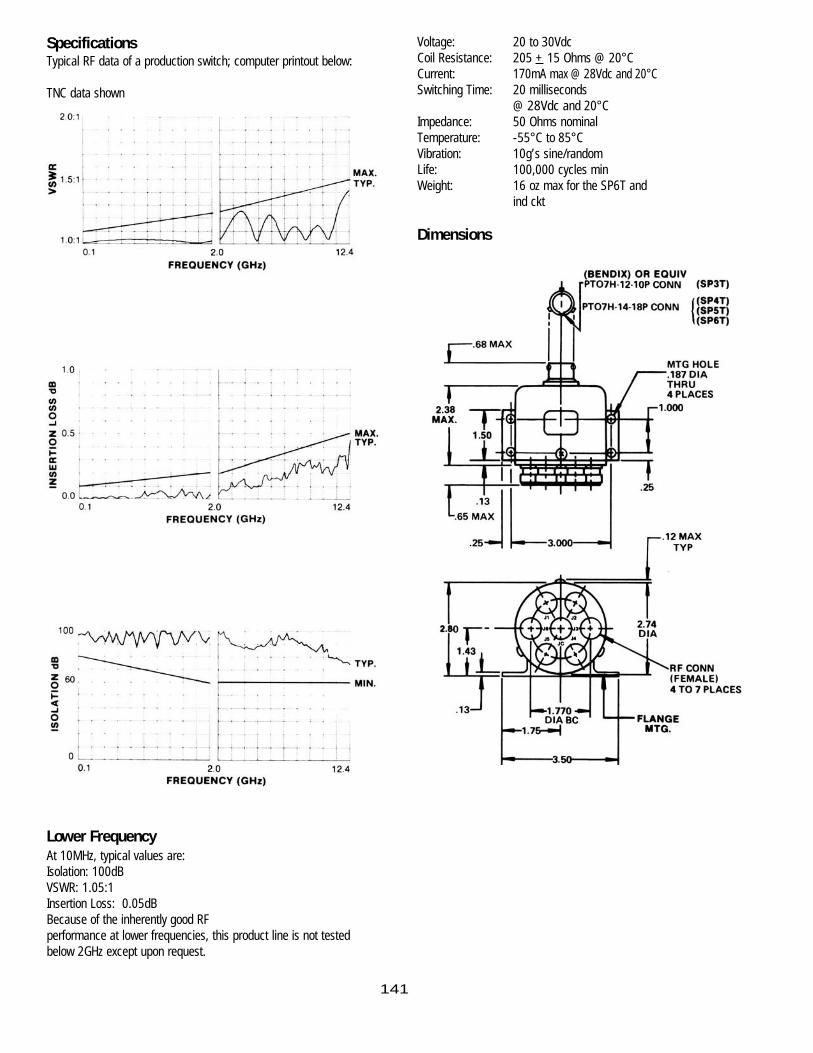
SpecificationsTypical RF data of a production switch; computer printout below:
TNC data shown
Lower FrequencyAt 10MHz, typical values are: Isolation: 100dB VSWR: 1.05:1Insertion Loss: 0.05dBBecause of the inherently good RF performance at lower frequencies, this product line is not testedbelow 2GHz except upon request.
Voltage: 20 to 30VdcCoil Resistance: 205 + 15 Ohms @ 20°CCurrent: 170mA max @ 28Vdc and 20°CSwitching Time: 20 milliseconds
@ 28Vdc and 20°CImpedance: 50 Ohms nominalTemperature: -55°C to 85°CVibration: 10g’s sine/randomLife: 100,000 cycles minWeight: 16 oz max for the SP6T and
ind ckt
Dimensions
141

Description
The Type MX coaxial switches are designed for high average powerapplications over a frequency band 0-6.5GHz. They use SC connec-tors, one-inch center-to-center spacing.
These switches utilize HCI (heat conducting dielectric) to increase theaverage power handling capabilities. Test results on a large number ofcomponents employing HCI have consistently indicated a CW power
rating 2.5 times greater than obtainable with conventional low-loss dielectric materials.
The Type MX SP3T to SP6T switch utilizes selected linear actuatorsfor each position. Individual solenoids mean faster switching time...nowaiting for the switch to sequence through a number of positionsbefore stopping at the selected position. These switches are availablewith or without mechanically activated indicating switches, giving pos-itive position indication.
This switch is part of a DowKey family of switches. Other types in thisfamily are referenced below.
Type Conn. Freq.M N & TNC 12.4GHzML N &TNC 12.4GHzMO SMA 18GHz
Designed to meet MIL-S-3928* Transco developed proprietary material
Standard ProductsP/N Pos Schematic Ind Ckt
133C51100 3 1 NO133C51200 3 1 YES134C51100 4 2 NO134C51200 4 2 YES135C51100 5 3 NO135C51200 5 3 YES136C51100 6 4 NO136C51200 6 4 YES
Coaxial Switch Type MX
RF Circuit: SP3T to SP6TActuator: Selective Connector: SCFrequency: 0-6.5GHz
Schematic#1. SP3T w/Indicator # 2. SP4T w/Indicator
# 3. SP5T w/Indicator # 4. SP6T w/Indicator
142
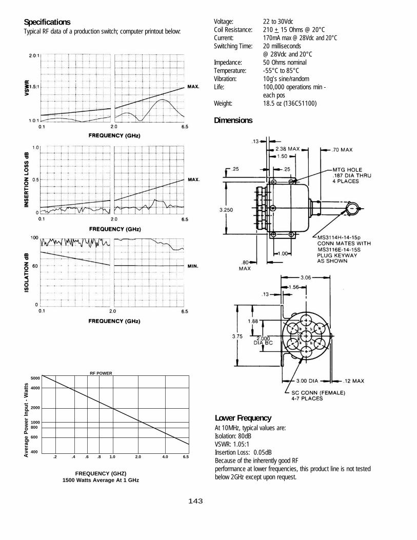
SpecificationsTypical RF data of a production switch; computer printout below:
Lower FrequencyAt 10MHz, typical values are: Isolation: 80dB VSWR: 1.05:1Insertion Loss: 0.05dBBecause of the inherently good RF performance at lower frequencies, this product line is not testedbelow 2GHz except upon request.
Voltage: 22 to 30VdcCoil Resistance: 210 + 15 Ohms @ 20°CCurrent: 170mA max @ 28Vdc and 20°CSwitching Time: 20 milliseconds
@ 28Vdc and 20°CImpedance: 50 Ohms nominalTemperature: -55°C to 85°CVibration: 10g’s sine/randomLife: 100,000 operations min -
each posWeight: 18.5 oz (136C51100)
Dimensions
Ave
rage
Pow
er In
put -
Wat
ts
FREQUENCY (GHZ)1500 Watts Average At 1 GHz
RF POWER5000
4000
2000
1000800
600
400.2 .4 .6 .8 1.0 2.0 4.0 6.5
143

Transco Products, Inc. Switches listed in MIL-S-55041C
SP2T FailsafeSpecification Sheet Option No. TPI Part No. FSN 5985
MIL-S-55041/3A /3-001 35D02800 _/3-002 32C01200 -/3-005 33D01300 -/3-006 33D00300 01-039-8434
Transfer LatchingSpecification Sheet Option No. TPI Part No. FSN 5985
MIL-S-55041/4A /4-001 33C00500 -/4-002 33D00200 00-009-4530
1P2T FailsafeSpecification Sheet Option No. TPI Part No. FSN 5985
MIL-S-55041/6A /6-001 33C12500 -
2P2T FailsafeSpecification Sheet Option No. TPI Part No. FSN 5985
MIL-S-55041/7A /7-001 33D00100-10 -/7-002 33D01100 -
1P2T LatchingSpecification Sheet Option No. TPI Part No. FSN 5985
MIL-S-55041/11 /11-001 33D08400 01-073-1529/11-002 33D06400 -/11-003 33D04400 -/11-004 33D03400 01-099-6613
00-009-3159/11-005 33D00400 -
Cross Reference Guide
144
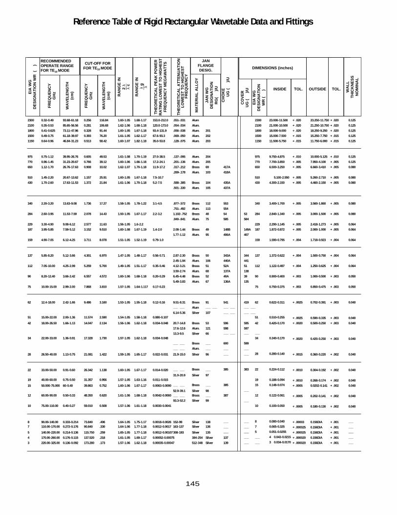
Reference Table of Rigid Rectangular Wavetable Data and FittingsE
IA W
GD
ES
IGN
AT
ION
WR
(
)
FR
EQ
UE
NC
YG
Hz
WA
VE
LEN
GT
H(c
m)
FR
EQ
UE
NC
YG
Hz
WA
VE
LEN
GT
H(c
m)
RA
NG
E IN
2 λ
___
λ c
RA
NG
E IN
λ g
___ λ
TH
EO
RE
TIC
AL
PE
AK
PO
WE
RR
AT
ING
LO
WE
ST
TO
HIG
HE
ST
FR
EQ
UE
NC
Y M
EG
AW
AT
TS
TH
EO
RE
TIC
AL
AT
TE
NU
AT
ION
LOW
ES
T T
O H
IGH
ES
TF
RE
QU
EN
CY
MA
TE
RIA
L A
LLO
Y
JAN
WG
D
ES
IGN
AT
ION
RG
(
)/
U
CH
OK
EU
G (
)/U
CO
VE
RU
G (
)/U
EIA
WG
DE
SIG
NA
TIO
NW
R (
) WA
LLT
HIC
KN
ES
SN
OM
INA
L
RECOMMENDEDOPERATE RANGEFOR TE10 MODE
JAN FLANGEDESIG. DIMENSIONS (inches)
INSIDE TOL.OUTSIDETOL.
CUT-OFF FORFOR TE10 MODE
2300 0.32-0.49 93.68-61.18 0.256 116.84 1.60-1.05 1.68-1.17 153.0-212.0 .051-.031 Alum 2300 23.000-11.500 + .020 23.250-11.750 + .020 0.125
2100 0.35-0.53 85.65-56.56 0.281 106.68 1.62-1.06 1.68-1.18 120.0-173.0 .054-.034 Alum. 2100 21.000-10.500 + .020 21.250-10.750 + .020 0.125
1800 0.41-0.625 73.11-47.96 0.328 91.44 1.60-1.05 1.67-1.18 93.4-131.9 .056-.038 Alum. 201 1800 18.000-9.000 + .020 18.250-9.250 + .020 0.125
1500 0.49-0.75 61.18-39.97 0.393 76.20 1.61-1.05 1.62-1.17 67.6-93.3 .069-.050 Alum. 202 1500 15.000-7.500 + .015 15.250-7.750 + .015 0.125
1150 0.64-0.96 46.84-31.23 0.513 58.42 1.60-1.07 1.82-1.18 35.0-53.8 .128-.075 Alum. 203 1150 11.500-5.750 + .015 11.750-6.000 + .015 0.125
975 0.75-1.12 39.95-26.76 0.605 49.53 1.61-1.08 1.70-1.19 27.0-38.5 .137-.095 Alum. 204 975 9.750-4.875 + .010 10.000-5.125 + .010 0.125
770 0.96-1.45 31.23-20.67 0.766 39.12 1.60-1.06 1.66-1.18 17.2-24.1 .201-.136 Alum. 205 770 7.700-3.850 + .005 7.950-4.100 + .005 0.125
650 1.12-1.70 26.76-17.63 0.908 33.02 1.62-1.07 1.70-1.18 11.9-17.2 .317-.212 Brass 69 417A 650 6.500-3.250 + .005 6.660-3.410 + .005 0.080
.269-.178 Alum. 103 418A
510 1.45-2.20 20.67-13.62 1.157 25.91 1.60-1.05 1.67-1.18 7.5-10.7 510 5.100-2.550 + .005 5.260-2.710 + .005 0.080
430 1.70-2.60 17.63-11.53 1.372 21.84 1.61-1.06 1.70-1.18 5.2-7.5 .588-.385 Brass 104 435A 430 4.300-2.150 + .005 4.460-2.150 + .005 0.080
.501-.330 Alum. 105 437A
340 2.20-3.20 13.63-9.08 1.736 17.27 1.58-1.05 1.78-1.22 3.1-4.5 .877-.572 Brass 112 553 340 3.400-1.700 + .005 3.560-1.860 + .005 0.080
.751-.492 Alum. 113 554
284 2.60-3.95 11.53-7.59 2.078 14.43 1.50-1.05 1.67-1.17 2.2-3.2 1.102-.752 Brass 48 54 53 284 2.840-1.340 + .005 3.000-1.500 + .005 0.080
.940-.641 Alum. 75 585 584
229 3.30-4.90 9.08-6.12 2.577 11.63 1.56-1.05 1.6-2.2 229 2.290-1.145 + .005 2.418-1.273 + .005 0.064
187 3.95-5.85 7.59-5.12 3.152 9.510 1.60-1.08 1.67-1.19 1.4-2.0 2.08-1.44 Brass 49 148B 149A 187 1.872-0.872 + .005 2.000-1.000 + .005 0.064
1.77-1.12 Alum. 95 406A 407
159 4.90-7.05 6.12-4.25 3.711 8.078 1.51-1.05 1.52-1.19 0.79-1.0 159 1.590-0.795 + .004 1.718-0.923 + .004 0.064
137 5.85-8.20 5.12-3.66 4.301 6.970 1.47-1.05 1.48-1.17 0.56-0.71 2.87-2.30 Brass 50 343A 344 137 1.372-0.622 + .004 1.500-0.750 + .004 0.064
2.45-1.94 Alum. 106 440A 441
112 7.05-10.00 4.25-2.99 5.259 5.700 1.49-1.05 1.51-1.17 0.35-0.46 4.12-3.21 Brass 51 52A 51 112 1.122-0.497 + .004 1.250-0.625 + .004 0.064
3.50-2.74 Alum. 68 137A 138
90 8.20-12.40 3.66-2.42 6.557 4.572 1.60-1.06 1.68-1.18 0.20-0.29 6.45-4.48 Brass 52 40A 39 90 0.900-0.400 + .003 1.000-0.500 + .003 0.050
5.49-3.83 Alum. 67 136A 135
75 10.00-15.00 2.99-2.00 7.868 3.810 1.57-1.05 1.64-1.117 0.17-0.23 75 0.750-0.375 + .003 0.850-0.475 + .003 0.050
62 12.4-18.00 2.42-1.66 9.486 3.160 1.53-1.05 1.55-1.18 0.12-0.16 9.51-8.31 Brass 91 541 419 62 0.622-0.311 + .0025 0.702-0.391 + .003 0.040___ ___ Alum ___ ___ ___ ___ ___ ___
6.14-5.36 Silver 107 ___ ___ ___ ___
51 15.00-22.00 2.00-1.36 11.574 2.590 1.54-1.05 1.58-1.18 0.080-0.107 51 0.510-0.255 + .0025 0.590-0.335 + .003 0.040
42 18.00-26.50 1.66-1.13 14.047 2.134 1.56-1.06 1.62-1.18 0.034-0.048 20.7-14.8 Brass 53 596 595 42 0.420-0.170 + .0020 0.500-0.250 + .003 0.040
17.6-12.6 Alum. 121 598 597
13.3-9.5 Silver 66 ___ ___ ___ ___
34 22.00-33.00 1.36-0.91 17.328 1.730 1.57-1.05 1.62-1.18 0.034-0.048 34 0.340-0.170 + .0020 0.420-0.250 + .003 0.040___ ___ Brass ___ 600 599
___ ___ Alum. ___ ___ ___
28 26.50-40.00 1.13-0.75 21.081 1.422 1.59-1.05 1.65-1.17 0.022-0.031 21.9-15.0 Silver 96 ___ ___ 28 0.280-0.140 + .0015 0.360-0.220 + .002 0.040
22 33.00-50.00 0.91-0.60 26.342 1.138 1.60-1.05 1.67-1.17 0.014-0.020 ___ ___ Brass ___ 385 383 22 0.224-0.112 + .0010 0.304-0.192 + .002 0.040
31.0-20.9 Silver 9719 40.00-60.00 0.75-0.50 31.357 0.956 1.57-1.05 1.63-1.16 0.011-0.015 19 0.188-0.094 + .0010 0.268-0.174 + .002 0.040
15 50.000-75.000 60-0.40 39.863 0.752 1.60-1.06 1.67-1.17 0.0063-0.0090 ___ ___ Brass ___ 385 15 0.148-0.074 + .0005 0.0202-0.141 + .002 0.040
52.9-39.1 Silver 98 ___
12 60.00-90.00 0.50-0.33 48.350 0.620 1.61-1.06 1.68-1.18 0.0042-0.0060 ___ ___ Brass ___ 387 12 0.122-0.061 + .0005 0.202-0.141 + .002 0.04093.3-52.2 Silver 99 ___
10 75.00-110.00 0.40-0.27 59.010 0.508 1.57-1.06 1.61-1.18 0.0030-0.0041 10 0.100-0.050 + .0005 0.180-0.130 + .002 0.040
8 90.00-140.00 0.333-0.214 73.840 .406 1.64-1.05 1.75-1.17 0.0018-0.0026 152-99 Silver 138 ___ ___ 8 0.080-0.040 + .00003 0.156DIA + .001 ___
7 110.00-170.00 0.272-0.176 90.840 .330 1.64-1.06 1.77-1.18 0.0012-0.0017 163-137 Silver 136 ___ ___ 7 0.065-0.325 + .000025 0.156DIA + .001 ___
5 140.00-220.00 0.214-0.136 115.750 .259 1.65-1.05 1.77-1.18 0.0012-0.00107 308-193 Silver 135 ___ ___ 5 0.051-0.0255 + .000025 0.156DIA + .001 ___
4 170.00-260.00 0.176-0.115 137.520 .218 1.61-1.05 1.69-1.17 0.00052-0.00075 384-254 Silver 137 ___ ___ 4 0.043-0.0215 + .000020 0.156DIA + .001 ___
3 220.00-325.00 0.136-0.092 173.280 .173 1.57-1.06 1.62-1.18 0.00035-0.00047 512-348 Silver 139 ___ ___ 3 0.034-0.0170 + .000020 0.156DIA + .001 ___
145

Description
The state-of-the-art Type GR Waveguide switch series with ten differ-ent waveguide sizes utilizes the unique transactor actuator. This directcoupled actuator is small in size and more reliable than older designsusing motors/gears, rotary or linear solenoids. The complete line isavailable failsafe or latching.
Standard ProductsThe following are standard for this switch series: failsafe or latching, choke flanges, pressurized, indicator circuits, 28Vdc, power connector.
Special ConfigurationActuating Voltage Transient Circuit
Transactor ActuatorTransco has used modern motor technology and combined the actuator rotor and switch RF rotor in a single integrated assembly. This exclusive design feature greatly extends the switch life.
RF Performance
2.60 3.30 3.95 4.90 5.85 7.05 7.05 8.20 10.00 12.40TO TO TO TO TO TO TO TO TO TO
3.95 4.90 5.86 7.05 8.20 10.00 11.00 12.40 15.00 18.001.15:1
MAX.1.10:1 TYP.
1.05:1
0.12
0.10 MAX.
.08 TYP.
.06
.04
.02
80
70TYP.
60 MIN.
50WR284 WR29 WR187 WR159 WR137 WR112 WR102 WR90 WR75 WR62
Waveguide Switch Type GR
RF Circuit: 3 or 4 PortActuator: Latching and FailsafeConnector: WR284 - WR62Frequency: 2.6-18GHz
Schematic
#1. Latching # 2. Failsafe
VS
WR
FREQUENCY Range (GHZ)
INS
ER
TIO
N L
OS
S d
BIs
olat
ion
dB
EIA WG DESIGNATION
146

Dimensions and Part Numbers
Positions: 3 or 4 portRF Power: equivalent to 90° E-Plane WG
bendActuator: “transactor”Voltage: 24 to 30VdcCurrent: see chartSwitching Time: see chartIndicator: for switching positionPressurized: 20 psigTemperature: -54°C to 95°CLife: 200,000 cycles min Finish: dull black
WAVE- SWITCH FREQUENCY SWITCHING CURRENT WEIGHTPART NO. GUIDE TYPE RANGE GHz TIME, MAX AMP MAX AA A B C D E F G H J K LBS.
SIZE (28Vdc, 20°C) MAX.33D00100 WR 62 A FAILSAFE 12.4 - 18.00 100MS .5 - 3.80 1.87 .877 1.850 .9375 1.875 .718 1.437 1.333D00200 WR 62 A LATCHING 1 - 4.0033D00300 WR 62 B FAILSAFE .5 .10 3.8033D00400 WR62 B LATCHING 12.4-18.00 1 .10 4.00 .877 1.333D09100 WR 75 A FAILSAFE 10.0 - 15.00 .5 - 3.95 .941 1.433D09200 WR 75 A LATCHING 1 - 4.1533D09300 WR 75 B FAILSAFE .5 .10 3.9533D09400 WR 45 B LATCHING 10.0-15.00 1 .10 4.15 .94133D01100 WR 90 A FAILSAFE 8.20-12.40 .5 - 4.05 1.01633D01200 WR 90 A LATCHING 1 - 4.3033D01300 WR 90 B FAILSAFE .5 .13 4.0533D01400 WR 90 B LATCHING 8.20-12.40 1 .13 4.30 1.87 1.016 1.850 .9375 1.875 .718 1.437 1.433D03200 WR 112 A LATCHING 7.05 - 10.00 1 - 5.10 2.07 1.245 2.25 1.187 2.375 1.000 2.000 2.333D03400 WR112 B LATCHING 7.05-10.00 100MS 1 .13 5.10 2.07 1.245 2.25 1.187 2.375 1.000 2.000 2.333D04200 WR 137 A LATCHING 5.85-8.20 150MS 1 - 7.00 2.57 1.750 3.25 2.125 4.250 1.750 3.500 8.333D04400 WR 137 B LATCHING 5.85-8.20 1 .13 7.00 1.750 8.333D06200 WR 187 A LATCHING 3.95-5.85 1 - 7.50 2.000 9.033D06400 WR 187 B LATCHING 3.95-5.85 150 MS 1 .13 7.50 2.00 2.125 4.250 1.750 3.500 9.033D08200 WR 284 A LATCHING 2.60-3.95 500 MS 1.5 - 9.00 2.750 2.937 5.875 2.375 4.750 17.033D08400 WR 284 B LATCHING 2.60-3.95 500 MS 1.5 .15 9.00 2.57 2.750 3.25 2.937 5.875 2.375 4.750 17.0
8-32 x.25 DEEP
8-32 x.25 DEEP
10-32 x.31 DEEP10-32 x
.31 DEEP1/4-20 X
.40 DEEP
1/4-20 X.40 DEEP1/4-20 X
.50 DEEP1/4-20 X
.50 DEEP
1/4-20 X.40 DEEP1/4-20 X
.40 DEEP
8-32 x.22 DEEP
8-32 x.22 DEEP
8-32 x.28 DEEP
8-32 x.28 DEEP10-32 x
.30 DEEP
10-32 x.30 DEEP
6-32 x.22 DEEP
6-32 x.22 DEEP
147

DescriptionThis is a broad band double ridge waveguide switch similar toDowKey’s standard type GR waveguide switches. This simple provendesign combines the actuator rotor and switch RF rotor in a singleintegrated assembly.
Transactor ActuatorThis is a low current bi-directional actuator developed byDowKey/Transco. Designed specifically for DowKey/Transco’s waveg-uide switches, this actuator uses torque motor principles conformingto MIL-M-8609 (DC motors) and MIL-M-7960 (AC motors).
Transactor does not require any mechanical coupling devices normallyassociated with conventional solenoid type actuators. This assureslong life and high reliability.
Standard Products
P/N Schematic Type30D01900 A 130D01400 B 1
Special ConfigurationActuating Voltage Transient Circuit
Other Products
P/N Schematic Type30D00500 B 2
Designed to meet MIL-S-55041
Waveguide Switch Type GF
RF Circuit: SPDT & TransferActuator: Latching and FailsafeConnector: WRD350D24Frequency: 3.5-8.2GHz
Schematic#1. Latching # 2. Failsafe
148

Specifications Actuator:Voltage: 24 to 30VdcCurrent: .85 amps max. @ 28Vdc, 20°CSwitching Time: 150 milliseconds maxDuty: continuos operationPressurized: 20 psigTemperature: -54°C to +84°CLife: 200,000 actuations minFinish: dull blackWeight: 9 lb. max
Dimensions
149

DescriptionThis is a broad band double ridge waveguide switch similar toDowKey/Transco’s standard type GR waveguide switches. It featuresthe same simple proven design of RF assembly and actuator assembly called “transactor”.
Transactor ActuatorThis is a low current bi-directional actuator developed byDowKey/Transco. Designed specifically for DowKey/Transco’s waveg-uide switches, this actuator uses torque motor principles conformingto MIL-M-8609 (DC motors) and MIL-M-7960 (AC motors).
Transactor does not require any mechanical coupling devices normallyassociated with conventional solenoid type actuators. This assureslong life and high reliability.
Standard Products
P/N Schematic Type30C01200 1 A30C01300 1 B
Special ConfigurationActuating Voltage Transient Circuit
Other Products
P/N Schematic Type30C02000 2 A30C02100 2 B
Waveguide Switch Type GF
RF Circuit: TransferActuator: Latching and FailsafeConnector: WRD750D24Frequency: 7.5-18GHz
Schematic
#1. Latching # 2. Failsafe
150

Specifications Actuator:Voltage: 24 to 30VdcCurrent: .80 amps max. @ 28Vdc, 20°CSwitching Time: 100 milliseconds maxDuty: continuous operationPressurized: 20 psigTemperature: -54°C to +84°CLife: 200,000 actuations minFinish: dull blackWeight: 1.3 lb. max
Dimensions
151