
Maximum Flexible Power (MFP) Single Output Point of Load
21
DESCRIPTION The Interpoint® MFP Series™ of DC-DC converters offers up to 16.5 watts of power in a radiation hardened design. (See Table 11 on page 21.) The low profile MFP converters are manufactured in our certified and qualified MIL-PRF-38534 Class K production facility and our Class H production facility. They packaged in hermetically sealed steel cases and are ideal for use in programs requiring high reliability, small size, and high levels of radiation hardness assurance. The MFP Series is a high-efficiency point of load converter with a 3.3 or 5 volt input, an undervoltage shutdown below 3.0 volts and an overvoltage shutdown above 6.0 volts. The non-isolated, feature-rich MFP uses a buck converter design with synchronous rectification. The design allows the unit to operate synchronously to no output load, ensuring high efficiency at the lightest loads without switching off the synchronous devices. Important features include a solid state switch, inrush current limiting, synchronization with an external system clock and the ability to current share allowing multiple devices to supply a common load. The MFP includes an internal house keeping supply that is active at inputs as low as 2 volts and provides a boosted and regulated voltage supply for internal use. This internal supply is one of the reasons that this product can provide full power at very high efficiency at input voltages as low as 3 volts. No external power source or external bias is required. The MFP converters are designed for the large, fast transient load currents typical to digital loads. See Figure 5 on page 12. The MFP Series is intended to be powered by a fully regulated power source. HISTORY OF PROVEN PERFORMANCE Crane Aerospace & Electronics, Power Solutions was issued its first standard microcircuit drawing (SMD) in 1992 for an Interpoint ® Class H hybrid. Our first Class K hybrid SMD was issued in 1997 and we were one of the first companies to certify manufacturing to Class K. Our facility has a Defense Logistics Agency (DLA) approved Radiation Hardness Assurance (RHA) plan. MAXIMUM FLEXIBLE POWER (MFP) IN A SINGLE 7 AMP POINT OF LOAD. A USE-ANYWHERE POWER SOLUTION FOR DIGITAL AND NON-DIGITAL SYSTEMS. FEATURES • Radiation hardened space DC-DC converter - Single event effects (SEE) LET performance to 86 MeV cm 2 /mg - Total ionizing dose (TID) guaranteed per method 1019 of MIL-STD-883, radiation hardness assurance (RHA) P = 30 krad(Si), L = 50 krad(Si) - 50 - 300 rad(Si)/sec dose rate - LDR tested to 30 krad at 10 mrad(Si)/sec • No external components required • Up to 92% typical efficiency, flat down to 30% load • Qualified up to MIL-PRF-38534 Class K • Vin 3.0 to 6.0 volts dc, transients up to 15 volts for 1 sec. • Inhibit and sync functions • Current monitoring • Current sharing pin for parallel operation • Four pin-selectable, preset voltages, 0.8, 1.6, 2.5 and 3.3 • Output voltage adjustable from 0.8 to 3.5 volts • Indefinite output short circuit protection • Adjustable start-up sequencing • Remote sense and voltage margining • Internal solid state power switch provides many benefits including inrush current limiting Maximum Flexible Power (MFP) Single Output Point of Load Page 1 of 21 MFP0507S Rev AN - 2021.04.06 MFP0507S, 3 TO 6 VOLT INPUT, 7 AMP, DC-DC CONVERTER Crane Aerospace & Electronics Power Solutions – Interpoint® Products 16706 13th Avenue West, Lynnwood, WA 98037 +1 425.882.3100 • [email protected] www.craneae.com/interpoint Crane Aerospace & Electronics Power Solutions
Transcript of Maximum Flexible Power (MFP) Single Output Point of Load

DESCRIPTIONThe Interpoint® MFP Series™ of DC-DC converters offers up to 16.5 watts of power in a radiation hardened design. (See Table 11 on page 21.) The low profile MFP converters are manufactured in our certified and qualified MIL-PRF-38534 Class K production facility and our Class H production facility. They packaged in hermetically sealed steel cases and are ideal for use in programs requiring high reliability, small size, and high levels of radiation hardness assurance. The MFP Series is a high-efficiency point of load converter with a 3.3 or 5 volt input, an undervoltage shutdown below 3.0 volts and an overvoltage shutdown above 6.0 volts.
The non-isolated, feature-rich MFP uses a buck converter design with synchronous rectification. The design allows the unit to operate synchronously to no output load, ensuring high efficiency at the lightest loads without switching off the synchronous devices. Important features include a solid state switch, inrush current limiting, synchronization with an external system clock and the ability to current share allowing multiple devices to supply a common load.
The MFP includes an internal house keeping supply that is active at inputs as low as 2 volts and provides a boosted and regulated voltage supply for internal use. This internal supply is one of the reasons that this product can provide full power at very high efficiency at input voltages as low as 3 volts. No external power source or external bias is required.
The MFP converters are designed for the large, fast transient load currents typical to digital loads. See Figure 5 on page 12. The MFP Series is intended to be powered by a fully regulated power source.
HISTORY OF PROVEN PERFORMANCECrane Aerospace & Electronics, Power Solutions was issued its first standard microcircuit drawing (SMD) in 1992 for an Interpoint® Class H hybrid. Our first Class K hybrid SMD was issued in 1997 and we were one of the first companies to certify manufacturing to Class K. Our facility has a Defense Logistics Agency (DLA) approved Radiation Hardness Assurance (RHA) plan.
MAXIMUM FLEXIBLE POWER (MFP) IN A SINGLE 7 AMP POINT OF LOAD.A USE-ANYWHERE POWER SOLUTION FOR DIGITAL AND NON-DIGITAL SYSTEMS.
FEATURES• Radiation hardened space DC-DC converter
- Single event effects (SEE) LET performance to 86 MeV cm2/mg
- Total ionizing dose (TID) guaranteed per method 1019 of MIL-STD-883, radiation hardness assurance (RHA) P = 30 krad(Si), L = 50 krad(Si)
- 50 - 300 rad(Si)/sec dose rate
- LDR tested to 30 krad at 10 mrad(Si)/sec
• No external components required
• Up to 92% typical efficiency, flat down to 30% load
• Qualified up to MIL-PRF-38534 Class K
• Vin 3.0 to 6.0 volts dc, transients up to 15 volts for 1 sec.
• Inhibit and sync functions
• Current monitoring
• Current sharing pin for parallel operation
• Four pin-selectable, preset voltages, 0.8, 1.6, 2.5 and 3.3
• Output voltage adjustable from 0.8 to 3.5 volts
• Indefinite output short circuit protection
• Adjustable start-up sequencing
• Remote sense and voltage margining
• Internal solid state power switch provides many benefits including inrush current limiting
Maximum Flexible Power (MFP) Single Output Point of Load
Page 1 of 21MFP0507S Rev AN - 2021.04.06
MFP0507S, 3 TO 6 VOLT INPUT, 7 AMP, DC-DC CONVERTER
Crane Aerospace & ElectronicsPower Solutions – Interpoint® Products16706 13th Avenue West, Lynnwood, WA 98037 +1 425.882.3100 • [email protected]/interpoint
Crane Aerospace & Electronics Power Solutions

Electrical Characteristics Tables
Table 1: Absolute Maximum Ratings . . . . . . . . . . . . . . . 3
Table 2: Input Specifications . . . . . . . . . . . . . . . . . . . 3
Table 3: Output Specifications . . . . . . . . . . . . . . . . . . 4
Pin Out
Table 4: MFP0507S Pin Out . . . . . . . . . . . . . . . . . . . 6
Model Numbering Information and SMD Number
Figure 1: Model Numbering Key . . . . . . . . . . . . . . . . . 7
Table 5: SMD Number Cross Reference . . . . . . . . . . . . . 7
Table 6: Model Number Options . . . . . . . . . . . . . . . . . 7
Mechanical Information
Figure 2: MFP0507S Case Dimensions . . . . . . . . . . . . . 8
Figure 3: MFP0507SF Case Dimensions. . . . . . . . . . . . . 9
Thermal and Mounting Considerations
Thermal Considerations . . . . . . . . . . . . . . . . . . . . . 10
Figure 4: Infrared Image MFP at Full Load . . . . . . . . . . 10
Mounting Considerations . . . . . . . . . . . . . . . . . . . . 11
Table 7: Chomeric Material Specifications . . . . . . . . . . 11
Pin Functions and Applications
Figure 5: Typical Connection Diagram . . . . . . . . . . . . . 12
ENABLE . . . . . . . . . . . . . . . . . . . . . . . . . . . . . 13
SYNC . . . . . . . . . . . . . . . . . . . . . . . . . . . . . . . 13
Figure 6: ENABLE and SYNC Equivalent Circuit . . . . . . 13
Table 8: Enable Capacitance Values . . . . . . . . . . . . 13
+VIN and VIN Common . . . . . . . . . . . . . . . . . . . . . 14
Figure 7: Input voltage vs Maximum Output Voltage . . . 14
SENSE . . . . . . . . . . . . . . . . . . . . . . . . . . . . . . 15
Figure 8: SENSE Pin Voltage Margining . . . . . . . . . . 15
SHARE . . . . . . . . . . . . . . . . . . . . . . . . . . . . . . 16
Figure 9: Typical Share Connection . . . . . . . . . . . . 16
TRIM A and TRIM B . . . . . . . . . . . . . . . . . . . . . . . 17
Table 9: User Configurable Output Voltages . . . . . . . 17
+VOUT and VOUT Common . . . . . . . . . . . . . . . . . . . . 17
Figure 10: Maximum Rated Output Current . . . . . . . . 17
Typical Performance Plots
Figure 11: Typical Efficiencies . . . . . . . . . . . . . . . . . 18
Figure 12: Input Ripple, 3 VIN . . . . . . . . . . . . . . . . . 18
Figure 13: Input Ripple, 5 VIN . . . . . . . . . . . . . . . . . 18
Figure 14: Output Ripple,1.2 VOUT . . . . . . . . . . . . . . . 18
Figure 15: Output Ripple, 3.3 VOUT . . . . . . . . . . . . . . 18
Figure 16: Load Transient Response, 1.2 VOUT . . . . . . . . 18
Figure 17: Load Transient Response, 3.3 VOUT . . . . . . . . 18
Figure 18: SHARE as Monitor for Output Current . . . . . . . 19
Figure 19: Typical OperaTing Frequency vs
TemperaTure and vin . . . . . . . . . . . . . . . . 19
Screening Tables
Table 10: envirOnmenTal screening . . . . . . . . . . . . . . 20
Table 11: radiaTiOn Hardness assurance . . . . . . . . . . . 21
TABLE OF CONTENTS
Crane Aerospace & Electronics Power Solutions
Maximum Flexible Power (MFP) Single Output Point of Load
MFP0507S, 3 TO 6 VOLT INPUT, 7 AMP, DC-DC CONVERTER
Page 2 of 21www.craneae.com/interpointMFP0507S Rev AN - 2021.04.06

Table 1 Notes1. Passed 500 volts. 2. Caution: Heat from reflow or wave soldering may damage the device. Solder pins individually with heat application not exceeding 300°C for 10 seconds per pin.
Crane Aerospace & Electronics Power Solutions
Maximum Flexible Power (MFP) Single Output Point of Load
MFP0507S, 3 TO 6 VOLT INPUT, 7 AMP, DC-DC CONVERTER
Page 3 of 21www.craneae.com/interpointMFP0507S Rev AN - 2021.04.06
Table 1: absOluTe maximum raTings
PARAMETER CONDITION FIGURE SYMBOL MIN TYP MAX UNITS
OPERATING TEMPERATURE 883, HP, HL, KP AND KL All — TC -55 — +125 °C
STORAGE TEMPERATURE All — TSTG -65 — +150 °C
DERATING OUTPUT POWER/CURRENT Linearly From 100% at 125°C to 0% at 135°C
MAXIMUM WEIGHT – MFP0507S — Figure 2 — — — 26 grams
ESD RATING 1 MIL-PRF-38534, 3.9.5.8.2, MIL-STD-883
METHOD 3015— — Class 1B 500 - 999 2 V
LEAD SOLDERING TEMPERATURE 210 seconds
max — — — — 300 °C
Table 2: inpuT speciFicaTiOns
PARAMETER STATE CONDITION FIGURE SYMBOL MIN TYP MAX UNITS
Input Voltage Range Continuous Figure 7 VIN 0 5.0 6.0 V
See Note 1 VOUT = V1, V2
Figure 7 3.0 3.3 or 5.0 6.0
Operating 2, 3 VOUT = V1, V2, V3
Figure 7VIN 3.3 3.3 or 5.0 6.0
V
VOUT = V1, V2, V3, V4
Figure 7 4.5 5.0 6.0
Transient Figure 7 VIN TRAN — — 15 V
Input Current VIN 3.3 V, VOUT 0.8 V — — 210 330No Load
VIN 5.0 V, VOUT 3.3 V —IIN
— 135 180mA
Disabled 4 VIN 3.3 V — — 105 145
VIN 5.0 V — — 50 90
Enable/DisableInput
Open Circuit Voltage Pin 1 OpenVIN 3.0 to 6.0 V
Figure 6 VPIN 1 1.6 2.0 2.6
Threshold Unit Enabled 2.3 — —
V
Threshold Unit Disabled VIN 3.0 to 6.0 V
Figure 6VPIN 1
— — 1.4
ENABLE Pin CurrentUnit Disabled IPIN 1 — — 2 mA
External Synchronization
Standard Sync Range Figure 6 — 270 — 600 kHz
Amplitude IOUT 5 A — — 3.0 5.0 6.0 V
Duty Cycle 5 — — 40 50 60 %
Frequency Source Impedance — — — — 50 Ohms
ELECTRICAL CHARACTERISTICS: -55 to +125°C TC, 5 VIN, 3.3 VOUT, nominal frequency, unless otherwise specified.
Crane Aerospace & Electronics Power Solutions
Maximum Flexible Power (MFP) Single Output Point of Load
MFP0507S, 3 TO 6 VOLT INPUT, 7 AMP, DC-DC CONVERTER
Page 4 of 21www.craneae.com/interpointMFP0507S Rev AN - 2021.04.06
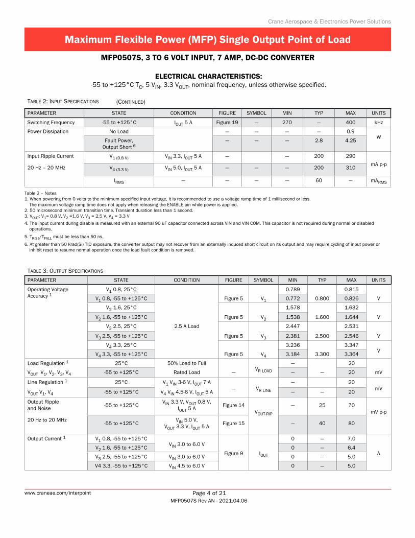
Table 3: OuTpuT speciFicaTiOns PARAMETER STATE CONDITION FIGURE SYMBOL MIN TYP MAX UNITS
Operating VoltageAccuracy 1
V1 0.8, 25°C 0.789 0.815
V1 0.8, -55 to +125°C Figure 5 V1 0.772 0.800 0.826 V
V2 1.6, 25°C 1.578 1.632
V2 1.6, -55 to +125°C Figure 5 V2 1.538 1.600 1.644 V
V3 2.5, 25°C 2.5 A Load 2.447 2.531
V3 2.5, -55 to +125°C Figure 5 V3 2.381 2.500 2.546 V
V4 3.3, 25°C 3.236 3.347
V4 3.3, -55 to +125°C Figure 5 V4 3.184 3.300 3.364V
Load Regulation 1 25°C 50% Load to Full — 20
VOUT V1, V2, V3, V4 -55 to +125°C Rated Load —VR LOAD — — 20 mV
Line Regulation 1 25°C V1 VIN 3-6 V, IOUT 7 A — 20
VOUT V1, V4 -55 to +125°C V4 VIN 4.5-6 V, IOUT 5 A— VR LINE — — 20
mV
Output Ripple and Noise -55 to +125°C
VIN 3.3 V, VOUT 0.8 V, IOUT 5 A Figure 14
VOUT-RIP
— 25 70mV p-p
20 Hz to 20 MHz-55 to +125°C
VIN 5.0 V, VOUT 3.3 V, IOUT 5 A Figure 15 — 40 80
Output Current 1 V1 0.8, -55 to +125°C 0 — 7.0
V2 1.6, -55 to +125°CVIN 3.0 to 6.0 V
0 — 6.4
V3 2.5, -55 to +125°C VIN 3.0 to 6.0 VFigure 9 IOUT 0 — 5.0
A
V4 3.3, -55 to +125°C VIN 4.5 to 6.0 V 0 — 5.0
ELECTRICAL CHARACTERISTICS: -55 to +125°C TC, 5 VIN, 3.3 VOUT, nominal frequency, unless otherwise specified.
Table 2: inpuT speciFicaTiOns
PARAMETER STATE CONDITION FIGURE SYMBOL MIN TYP MAX UNITS
Switching Frequency -55 to +125°C IOUT 5 A Figure 19 — 270 — 400 kHz
Power Dissipation No Load — — — — 0.9
Fault Power, Output Short 6
— — — 2.8 4.25W
Input Ripple Current V1 (0.8 V) VIN 3.3, IOUT 5 A — — 200 290
20 Hz – 20 MHz V4 (3.3 V) VIN 5.0, IOUT 5 A — — — 200 310mA p-p
IRMS — — — — 60 — mARMS
Table 2 – Notes 1. When powering from 0 volts to the minimum specified input voltage, it is recommended to use a voltage ramp time of 1 millisecond or less.
The maximum voltage ramp time does not apply when releasing the ENABLE pin while power is applied. 2. 50 microsecond minimum transition time. Transient duration less than 1 second.3. VOUT: V1= 0.8 V, V2 =1.6 V, V3 = 2.5 V, V4 = 3.3 V
4. The input current during disable is measured with an external 90 uF capacitor connected across VIN and VIN COM. This capacitor is not required during normal or disabled operations.
5. TRISE/TFALL must be less than 50 ns.
6. At greater than 50 krad(Si) TID exposure, the converter output may not recover from an externally induced short circuit on its output and may require cycling of input power or inhibit reset to resume normal operation once the load fault condition is removed.
(cOnTinued)

Crane Aerospace & Electronics Power Solutions
Maximum Flexible Power (MFP) Single Output Point of Load
MFP0507S, 3 TO 6 VOLT INPUT, 7 AMP, DC-DC CONVERTER
Page 5 of 21www.craneae.com/interpointMFP0507S Rev AN - 2021.04.06
Table 3: OuTpuT speciFicaTiOns PARAMETER STATE CONDITION FIGURE SYMBOL MIN TYP MAX UNITS
Output Power 1 V1 0.8, -55 to +125°C 0 — 5.6
V2 1.6, -55 to +125°CVIN 3.0 to 6.0 V
0 — 10.2
V3 2.5, -55 to +125°C VIN 3.0 to 6.0 VFigure 9 POUT 0 — 12.5
W
V4 3.3, -55 to +125°C VIN 4.5 to 6.0 V 0 — 16.5
External Load— — — — — — 5000 µF
Capacitance 2
Efficiency 1 V1 0.8, 25°C 70.0 73 —
V1 0.8, -55 to +125°CFigure 11 EFF1 67.4 — —
%
V2 1.6, 25°C 81.8 84 —
V2 1.6, -55 to +125°C IOUT 5 AFigure 11 EFF2 80.0 — —
%
V3 2.5, 25°C 87.3 89 —
V3 2.5, -55 to +125°CFigure 11 EFF3 85.8 — —
%
V4 3.3, 25°C 90.1 92 —
V4 3.3, -55 to +125°CFigure 11 EFF4 88.8 — —
%
Turn On Peak Release of Enable IOUT No Load to Full — — — — 50mV pk
Deviation, VOUT, V4 1, 3 VIN Step Start VIN 0 to 5.0 V — — — 50
Turn On Settling Time Release of Enable IOUT No Load to Full — — — 3.2 5ms
to 2%, VOUT, V4 1, 3 VIN Step Start VIN 0 to 5.0 V — — 3.2 5
Output Load VIN 3.3 V, VOUT 0.8 V IO 2.5 to 5 A — — 350 400µsTransient Response
VIN 5.0 V, VOUT 3.3 V@ 1 A / µs
settle to 2%
Figure 16Figure 17 — — 140 200
Load Transient Peak VIN 3.3 V, VOUT 0.8 V IO 2.5 to 5 A — — 210 244mV pkDeviation
VIN 5.0 V, VOUT 3.3 V@ 1 A/µs
settle to 2%
Figure 16Figure 17 — — 150 220
Output Voltage Trim 1V1, V2, V3, V4
— See Table 9 on page 17
Sequence Time Delay See Table 8 on page 13
MTBFMFP0507S/H
AIF @ 55°C— — — 1680 —
kHrsMFP0507S/K — — — 6722 —
Table 3 – Notes1. VOUT is defined by the subscript after the V: V1= 0.8 V, V2 =1.6 V, V3 = 2.5 V, V4 = 3.3 V
2. Guaranteed stable up to maximum capacitance. 3. Test condition at VOUT at 3.3 V based on worst case setpoint condition.
ELECTRICAL CHARACTERISTICS: -55 to +125°C TC, 5 VIN, 3.3 VOUT, nominal frequency, unless otherwise specified.
(cOnTinued)

PIN OUT
Pin Number Designation Function If Pin is not Used
1 ENABLE Enable, provides remote turn on and off Leave open
2 +V IN Positive Input Always used
3 V IN COM Input Common Always used
4 SYNC Synchronization Leave open
5 SENSE Sense, voltage drop compen-sation Connect to + VOUT pin 10
6 SHARE Current Share, parallel opera-tion, or current monitor Leave open
7 TRIM A Preset Output Voltage and Trim
See Figure 5 on page 12 and Table 9 on page 17
8 TRIM B Preset Output Voltage and Trim
See Figure 5 on page 12 and Table 9 on page 17
9 V OUT COM Output Common (also SENSE Return) Always used
10 +V OUT Positive Output Always used
Table 4: mFp0507s pin OuT
Crane Aerospace & Electronics Power Solutions
Maximum Flexible Power (MFP) Single Output Point of Load
MFP0507S, 3 TO 6 VOLT INPUT, 7 AMP, DC-DC CONVERTER
Page 6 of 21www.craneae.com/interpointMFP0507S Rev AN - 2021.04.06

Figure 1: mOdel numbering Key
MODEL NUMBERING KEY
MFP 05 07 S F / KLMaximum Flexible Power
Nominal Input Voltage
Output Current
Screening and RHA
Number of Outputs(S = single)
(/ST, /883, HP, HL, KP or KL)
Case Option(Non-flanged case has no designator in this position)
MODEL NUMBER OPTIONS 1
To deTermine The model number enTer one opTion from each caTegory in The form below.
CATEGORYBase Model,
Input Voltage and Output Current
Case Option 2 Screening 3 RHA 4
MFP0507S (non-flanged, leave blank) ST NA
F (flanged) 883 NA
O O
H P
K L
FILL IN FOR MODEL # 5 MFP0507S__________ _______ / _______
Notes1. See Figure 1 above for an example of a model number. 2. Case Options: For the standard case (Figure 2 on page 8) leave the Case Option blank. For the flanged case option
(Figure 3 on page 9), insert the letter F in the Case Option position. 3. High Reliability Screening: A screening level of /ST is standard screening and /883 is Class H screening. Space Screening: A screening level of O is a space prototype and is only available with RHA O.
See Table 10 on page 20 and Table 11 on page 21 for more information.4. RHA: Interpoint model numbers use an “O” in the RHA designator position to indicate the “-” (dash) radiation hardness
assurance level of MIL-PRF-38534, which is defined as “no RHA.” RHA O is only available with screening level O, see Table 10 on page 20. See Table 11 on page 21 for RHA P or L information.
5. If ordering by model number add suffix “-Q” to request solder dipped leads (MFP0507S/KL-Q).
SMD NUMBERSTandard microcircuiT
drawing (Smd)mfp Similar parT
5962L1120902KXC MFP0507S/KL
The SMD numbers shown are for RHA level L, screening level Class K, standard case (X), standard pin seal and non-solder dipped pins (C). For other options please refer to the SMD for the SMD number and the vendor similar number. All SMD numbers are listed on the SMD in the “Bulletin” which is the last page of the SMD. For exact specifications for an SMD product, refer to the SMD. SMDs can be downloaded from https://landandmaritimeapps.dla.mil/programs/smcr
Table 5: smd number crOss reFerence
Table 6: mOdel number OpTiOns
Crane Aerospace & Electronics Power Solutions
Maximum Flexible Power (MFP) Single Output Point of Load
MFP0507S, 3 TO 6 VOLT INPUT, 7 AMP, DC-DC CONVERTER
Page 7 of 21www.craneae.com/interpointMFP0507S Rev AN - 2021.04.06

Crane Aerospace & Electronics Power Solutions
Maximum Flexible Power (MFP) Single Output Point of Load
MFP0507S, 3 TO 6 VOLT INPUT, 7 AMP, DC-DC CONVERTER
Page 8 of 21www.craneae.com/interpointMFP0507S Rev AN - 2021.04.06
MECHANICAL INFORMATION
Weight: 26 grams maximum
Case dimensions in inches (mm)Tolerances, unless otherwise specified,X.XXX (X.XX) = ±0.005 (0.13)X.XX (X.X) = ±0.01 (0.30)Pin and hole placement ±0.0035 (±0.089) CAUTIONHeat from reflow or wave soldering may damage the device. Solder pins individually with heat application not exceeding 300°C for 10 seconds per pin.
Materials Header - Cold Rolled Steel/Nickel or Cold Rolled Steel/Nickel/Gold Cover - Kovar/Nickel Pins - 3:1 Cu Cored alloy 52/Gold over Nickel, compression glass seal Gold plating of 50 - 150 microinches included in pin diameter Seal hole: 0.091 ±0.003 (2.31 ±0.08)
Please refer to the numerical dimensions for accuracy.
Case D3, Rev E, 2020.07.09 font
MFP Series SingleTOP VIEW CASE D3
1.200 max(30.48)
10 x 0.190 (4.83)
0.346 max. (8.79)Seam seal
1
2
3
4
5
6
10
9
8
7
0.972 (24.69)
0.672 (17.07)
0.822 (20.88)
0.522 (13.26)
0.372 (9.45)
0.222 ±0.010 (5.64 ±.025)
0.040 ±0.002 dia.(1.02 ±.05)
0.240 ±0.010(6.10 ±0.25)
1.200 max(30.48)
Figure 2: mFp0507s case dimensiOns

Crane Aerospace & Electronics Power Solutions
Maximum Flexible Power (MFP) Single Output Point of Load
MFP0507S, 3 TO 6 VOLT INPUT, 7 AMP, DC-DC CONVERTER
Page 9 of 21www.craneae.com/interpointMFP0507S Rev AN - 2021.04.06
MECHANICAL INFORMATION
Weight: 32 grams maximum
Case dimensions in inches (mm)Tolerances, unless otherwise specified,X.XXX (X.XX) = ±0.005 (0.13)X.XX (X.X) = ±0.01 (0.30)Pin and hole placement ±0.0035 (±0.089) CAUTIONHeat from reflow or wave soldering may damage the device. Solder pins individually with heat application not exceeding 300°C for 10 seconds per pin.
Materials Header - Cold Rolled Steel/Nickel or Cold Rolled Steel/Nicke. Gold plating /883 only Cover - Kovar/Nickel Pins - 3:1 Cu Cored alloy 52/Gold over Nickel, compression glass seal Gold plating of 50 - 150 microinches included in pin diameter Seal hole: 0.091 ±0.003 (2.31 ±0.08)
Please refer to the numerical dimensions for accuracy.
Case D5, Rev D, 2020.07.09 font
TOP VIEW CASE D5
1.200 max(30.48)
0.450 (11.43)
0.373(9.47)
0.000
1
2
3
4
5
6
10
9
8
7
0.00
0
0.972 (24.69)
0.672 (17.07)
0.822 (20.88)
0.522 (13.26)
0.372 (9.45)
0.118 (2.99)
0.222 ±0.010 (5.64 ±.025)
10 x 0.190 (4.83) 0.356 max. (9.04)
Seam seal0.040 ±0.002 dia.(1.02 ±.05)
0.240 ±0.010(6.10 ±0.25)
Flan
ge th
ickn
ess:
0.0
40 (1
.01)
Base Plate Detail, Edge View
1.675 ± .015(42.54 ± 3.8)
1.313 (33.35)
2 x Ø 0.100 ± 0.004 (2.54 ± 0.10)
2 x R. 0.122 (3.09)
4 x 138°
Figure 3: mFp0507sF case dimensiOns
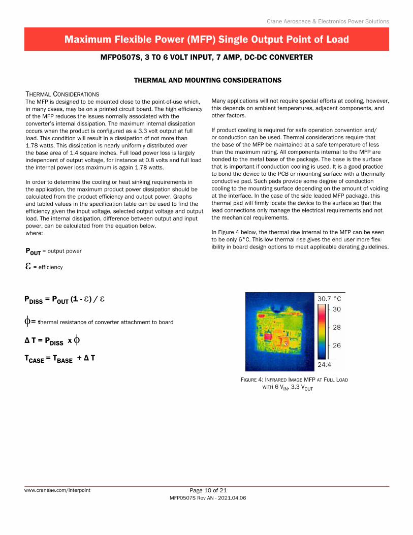
THermal cOnsideraTiOnsThe MFP is designed to be mounted close to the point-of-use which, in many cases, may be on a printed circuit board. The high efficiency of the MFP reduces the issues normally associated with the converter’s internal dissipation. The maximum internal dissipation occurs when the product is configured as a 3.3 volt output at full load. This condition will result in a dissipation of not more than 1.78 watts. This dissipation is nearly uniformly distributed over the base area of 1.4 square inches. Full load power loss is largely independent of output voltage, for instance at 0.8 volts and full load the internal power loss maximum is again 1.78 watts.
In order to determine the cooling or heat sinking requirements in the application, the maximum product power dissipation should be calculated from the product efficiency and output power. Graphs and tabled values in the specification table can be used to find the efficiency given the input voltage, selected output voltage and output load. The internal dissipation, difference between output and input power, can be calculated from the equation below.where:
POUT = output power
ε = efficiency
Many applications will not require special efforts at cooling, however, this depends on ambient temperatures, adjacent components, and other factors.
If product cooling is required for safe operation convention and/or conduction can be used. Thermal considerations require that the base of the MFP be maintained at a safe temperature of less than the maximum rating. All components internal to the MFP are bonded to the metal base of the package. The base is the surface that is important if conduction cooling is used. It is a good practice to bond the device to the PCB or mounting surface with a thermally conductive pad. Such pads provide some degree of conduction cooling to the mounting surface depending on the amount of voiding at the interface. In the case of the side leaded MFP package, this thermal pad will firmly locate the device to the surface so that the lead connections only manage the electrical requirements and not the mechanical requirements.
In Figure 4 below, the thermal rise internal to the MFP can be seen to be only 6°C. This low thermal rise gives the end user more flex-ibility in board design options to meet applicable derating guidelines.
THERMAL AND MOUNTING CONSIDERATIONS
PDISS = POUT (1 - ε) / ε
φ= thermal resistance of converter attachment to board
∆ T = PDISS x φTCASE = TBASE + ∆ T
Crane Aerospace & Electronics Power Solutions
Maximum Flexible Power (MFP) Single Output Point of Load
MFP0507S, 3 TO 6 VOLT INPUT, 7 AMP, DC-DC CONVERTER
Page 10 of 21www.craneae.com/interpointMFP0507S Rev AN - 2021.04.06
wiTH 6 vin, 3.3 vOuT
Figure 4: inFrared image mFp aT Full lOad

mOunTing cOnsideraTiOnsThe recommended mounting material is Chomeric’s double-sided adhesive materials for attachment of the MFP to a circuit board or metal surface.
Because of the MFP’s efficiency the thermal characteristics of the Chomeric materials are not required even though the Chomeric material provides good thermal conductivity.
The following information refers to products attached using Chomeric double-sided adhesive.
Vibration TestingThe MFP was tested in Random vibration using both the T1680 and T404 to mount the units to an aluminum vibration fixture. Testing was performed to the most severe level in MIL-STD-883 Method 2026; Condition 2, Letter K, overall GRMS 51.1, for 15 minutes per axis, 3 axes and passed. No mounting detachment occurred.
ApplicationRecommended size for the adhesive tapes is 1.18 x 1.18 inches. Application of the tapes is a matter of peeling the release liners and attaching to the MFP and circuit board respectively. See Chomeric’s data sheets and application notes for details. The T404 material does require higher application pressure. The T1680 material is specifically made for low pressure attachment of hybrids, ceramic and flat packages.
RemovalRefer to Chomeric’s application notes for Thermattach Tape.
SpecificationsRefer to Table 7: Chomeric Material Specifications for thermal conductivity, temperature range and out-gassing.
MATERIAL
THERMAL CONDUCTIVITY
TEMPERATURE RANGE OUTGASSING DATA MOUNTING
APPLICATIONW/M-K °C % TVM % CVCM
CHO-THERM 1671 (Note 1) 2.6 -60 to +200 0.76 0.07 Rougher surfaces
CHO-THERM T1680 (Note 2) 0.65 -60 to +200 1.27 0.23 Smooth surfaces
THERMATTACH T404 (Note 2) 0.4 -30 to +125 0.53 0.02 Smooth surfaces
THERMAL AND MOUNTING CONSIDERATIONS (CONTINUED)
Table 7 – Notes1. Chomerics Cho-Therm 1671 is a good choice for mounting on
rougher surfaces. This material has a fiberglass barrier with PSA on one side. It can be obtained with PSA on both sides if needed.
2. Chomeric’s Thermattach Tape T404 and Cho-Therm T1680 are two excellent choices for circuit board mounting. Both have a Kapton insulating barrier with pressure sensitive adhesive (PSA) on both sides.
Table 7: cHOmeric maTerial speciFicaTiOns
Crane Aerospace & Electronics Power Solutions
Maximum Flexible Power (MFP) Single Output Point of Load
MFP0507S, 3 TO 6 VOLT INPUT, 7 AMP, DC-DC CONVERTER
Page 11 of 21www.craneae.com/interpointMFP0507S Rev AN - 2021.04.06

For more information: TRIM section Remote SENSE section ENABLE section, sequencing. Table 8 on page 13 lists CT values. SHARE section
1 2
3
4
5
+ V IN
EN
V IN COM
SYNC IN
SENSE
SHARE
+V OUT
V OUT COM
TRIM B
TRIM A
MFP Single POL Converter
+ V IN
EN
V IN COM
SYNC IN
SENSE
SHARE
+V OUT
V OUT COM
TRIM B
TRIM A
MFP Single POL Converter
+ V IN
EN
V IN COM
SYNC IN
SENSE
SHARE
+V OUT
V OUT COM
TRIM B
TRIM A
MFP Single POL Converter
+ V IN
EN
V IN COM
SYNC IN
SENSE
SHARE
+V OUT
V OUT COM
TRIM B
TRIM A
MFP Single POL Converter
12.7 k
External ENABLE
+
–
IOUTMonitoring
3.3 VLoad + _
2.5 VLoad
+ _
1.2 VLoad
+ _
0.8 VLoad + _
VIN DC
CT4
CT3
CT1
CT2
1
2
3
45
Figure 5: Typical cOnnecTiOn diagram
enable, Trim, sense, and iOuT mOniTOring
design recOmmendaTiOnsThe MFP is designed to be used with a low impedance power source. If the inductance to the MFP input is not negligible, it is recommended that the inductance is kept to less than 1 uH per MFP converter. For additional information please contact Applications Engineering application support at [email protected].
Crane Aerospace & Electronics Power Solutions
Maximum Flexible Power (MFP) Single Output Point of Load
MFP0507S, 3 TO 6 VOLT INPUT, 7 AMP, DC-DC CONVERTER
Page 12 of 21www.craneae.com/interpointMFP0507S Rev AN - 2021.04.06

enableThe MFP provides an enable pin that will allow normal power conversion to occur if left open or unconnected. The ENABLE pin allows remote turn-on and turn-off control of the MFP. Connecting this pin to ground will disable power conversion, resulting in no output voltage and greatly reduced current consumption. The MFP ENABLE function will work with an open collector device connected to the pin or with a logic high voltage from a digital device as long as the logic high voltage is greater than the minimum voltage listed in the specification for enabled operation. The enable pin is active high at > 2.3 volts or with a floating input.
Sequencing: The start-up of the MFP can be delayed with the addition of an external capacitor connected to the ENABLE pin as shown in Figure 6. This feature is useful in sequencing the start-up of multiple point of load converters in a system requiring a specific startup sequence for various low-voltage loads. The startup delay is roughly equal to 1 millisecond per microfarad of capacitance. More precise external capacitance values can be found in Table 8 where it can be seen that there is a variation in startup delay time as the input voltage varies. The listed delay is from the beginning of application of power to the beginning of internal power conversion. There will be an additional delay as the power converter begins a normal start-up sequence and ramps to final output voltage.
syncThe MFP includes a synchronization feature, a key capability in low noise system design. The internal conversion oscillator can be synchronized with a system clock or with a bus voltage source. The MFP is designed to synchronize with a 300 kHz system but can be synchronized with sources up to 600 kHz, a frequency range used by many DC-DC converters. A synchronized system prevents the generation of low frequency sub harmonics in the audio range. The synchronization input amplitude can range from 3 to 6 volts. Figure 18 on page 19 illustrates the relationship between operating frequency, temperature and input voltage.
The external synchronization timing cycle can be varied cycle to cycle for systems employing spread-spectrum clocking or for slave sharing clock interleaving. The dc level of the sync pin can be used to detect the state of the input voltage protection switch.
ENABLE
+ V IN
V IN COM
SYNC IN
V OUT COM
+V OUT
2.2 k 22.1 k
5.11 k
220 µF
330 µF
Case
CONTROL
CLOCK
HOUSEKEEPING
UNDER VOLTAGE / OVER VOLTAGE
PROTECTION
DC-DC
Figure 6: enable and sync equivalenT circuiT
ENABLE CAPACITANCE: DELAY FROM ENABLE RELEASE TO START OF OUTPUT RISE (25°C) UNITS
CAPACITANCE (CT) 0.22 0.33 0.47 0.68 1.0 1.5 2.2 3.3 4.7 6.8 10 µF
VIN 3.3 V 0.8 1.1 1.6 2.2 3.1 4.6 6.7 10.0 14.1 20.2 29.7 ms
VIN 5.0 V 0.4 0.5 0.7 0.9 1.3 1.8 2.6 3.9 5.5 7.8 11.4 ms
Table 8: enable capaciTance values FOr sTarT-up delay
Crane Aerospace & Electronics Power Solutions
Maximum Flexible Power (MFP) Single Output Point of Load
MFP0507S, 3 TO 6 VOLT INPUT, 7 AMP, DC-DC CONVERTER
Page 13 of 21www.craneae.com/interpointMFP0507S Rev AN - 2021.04.06

+vin and vin cOmmOn
Input VoltageThe input voltage range for normal operating conditions is 3.0 to 6.0 volts (Figure 7). For input ripple current see Figure 12 and Figure 13 on page 18.
The VIN Common pin is connected to VOUT Common and case ground. The input and output should share the same ground plane in the power system design.
addiTiOnal inpuT blOcK FeaTuresInput Under and Over Voltage ProtectionThe MFP includes a solid state switch on the input section. This switch opens for fault conditions including input voltages below the minimum and transient voltages above the maximum. The safe operating range includes ground and extends to 7.0 volts indefinitely and up to 15 volts as a time limited transient. The switch will only close when certain internal conditions are met, including the proper operation of the internal housekeeping supply and a safe input voltage range.
No Single Point FailureThe solid state switch (SSS) can be used to provide one additional level of reliability: “no single point failure” will result in a connection from input voltages to output loads. The SSS can be opened by grounding of the ENABLE Pin. The status of the SSS can be determined by detecting the voltage on the SYNC pin. A logic low on this pin indicates that the SSS is open.
No External Bias Required An internal housekeeping supply that is active at inputs as low as 2 volts provides a boosted and regulated voltage supply for internal use. This internal supply is one of the reasons that this product can provide full power at very high efficiency at input voltages as low as 3 volts. No external power source or external bias is required.
Input Reflected Noise and Inrush Current LimitSubstantial input capacitance is included and the input solid state switch previously described is designed to provide associated inrush current limiting. The substantial input capacitance and high SSS provide a “pi” filter configuration that results in very low reflected ripple current. The very low input noise and inrush limiter make the MFP unique among point of load converters.
Maximum Output Voltage Range
1.0 4.03.02.0 6.05.00
3.3
3.0
2.5
2.0
1.5
0.8
0
10.5 15.0
Input Voltage (V)O
utpu
t Dis
able
d
4.253.3
Unde
r Vol
tage
Shu
tdow
n
3.4
1.6
1.0
0.5
NormalOperation
Out
put V
olta
ge (V
)
Ove
r Vol
tage
Shu
tdow
n
0.64
Figure 7: inpuT vOlTage vs maximum OuTpuT vOlTage
Crane Aerospace & Electronics Power Solutions
Maximum Flexible Power (MFP) Single Output Point of Load
MFP0507S, 3 TO 6 VOLT INPUT, 7 AMP, DC-DC CONVERTER
Page 14 of 21www.craneae.com/interpointMFP0507S Rev AN - 2021.04.06

sense The MFP includes a positive remote sense. The SENSE pin is intended to be used to maintain the desired preset voltage at the point-of-use by connecting the remote sense to the +Vout supply in close proximity to the load. Up to 0.27 volts of power line drop can be accommodated. If the SENSE pin lead is not connected to the output positive power pin, the output will rise a total of 0.27 volts.
The output voltage can be margined upward from the preset value as much as 0.2 volts by the addition of a resistor between the positive SENSE pin and the output power pin. The amount of increase in the output voltage by margining will reduce the available remote sense range by the same amount. The sum of margined voltage and voltage sense drop must be less than 0.2 volts.
Sense margining can be used to adjust VOUT from 3.3 to 3.5. Connections must be made as close as possible to Common and to RX. This method uses the SENSE pin’s voltage compensation function to raise the output voltage. Therefore, there will not be an option to compensate for voltage drop at the load.
If connections have no voltage drop, the formula for the resistor is
RX = 1000 in ohms (0.2697) (VOUT - 3.3)-1
Rx
OU
+
-
V T
+VOUT
SENSE
TRIM A TRIM B
VOUT Common
Figure 8 – Notes1. For external connections see Figure 5 on page 12. 2. See Table 9 on page 17 for output voltages from 0.64 to 3.3.3. Not tested.
Figure 8: sense pin vOlTage margining
vOuT FrOm 3.3 TO 3.5 1, 2, 3
[ ]
Crane Aerospace & Electronics Power Solutions
Maximum Flexible Power (MFP) Single Output Point of Load
MFP0507S, 3 TO 6 VOLT INPUT, 7 AMP, DC-DC CONVERTER
Page 15 of 21www.craneae.com/interpointMFP0507S Rev AN - 2021.04.06

sHareThe MFP includes a current share feature that allows multiple units to operate as a single supply capable of providing a total current that is the sum of the maximum from each of the units that are operated in parallel. In connecting units in parallel, the SHARE pin is connected between units and all but one unit, the master, will have TRIM A and TRIM B pins tied to the positive SENSE pin. The master will have the TRIM pins configured for the desired output voltage while the other units in parallel will match the current and voltage of the master unit. The SHARE pin can be used as an output current monitor because the voltage on this pin is proportional to unit current. See Figure 5 on page 12, callout 5. Output currents corresponding to SHARE pin voltages are shown in Figure 18 on page 19. Connections for current monitoring are also shown in Figure 5 on page 12.
Two connections are critical to sharing between two units. The SHARE pins of the two (or more) units must be tied together and the TRIM A and TRIM B outputs must be tied together and shorted to +Vout and SENSE for each unit that is not the Master. The master unit will be the one with the highest pre-set output voltage. In the case of Figure 9, callout 3, the master is configured with both TRIM pins open for a 0.8 volt output.
EN
+ V IN
V IN COM
SYNC IN
SENSE
SHARE
+V OUT
V OUT COM
TRIM B
TRIM A
MFP Single POL Converter
MASTER
EN
+ V IN
V IN COM
SYNC IN
SENSE
SHARE
+V OUT
V OUT COM
TRIM B
TRIM A
MFP Single POL Converter
SLAVE
V IN DC+
–
SystemClock
DC-DC Converter
+
LOAD
—
+ V IN
V IN COM
SYNC IN SYNC OUT
INHIBIT
+V OUT
V OUT COM
1
2
31
2
3
For more information: ENABLE section SYNC section
SHARE section (above)
Figure 9: Typical sHare cOnnecTiOn
wiTH OpTiOnal sync
Crane Aerospace & Electronics Power Solutions
Maximum Flexible Power (MFP) Single Output Point of Load
MFP0507S, 3 TO 6 VOLT INPUT, 7 AMP, DC-DC CONVERTER
Page 16 of 21www.craneae.com/interpointMFP0507S Rev AN - 2021.04.06

Trim a and Trim bOutput Voltage Set and AdjustmentThe MFP0507S, single output model has the flexibility to be set for any voltage from 0.64 to 3.3 volts. The MFP includes five precision set-points that can be accomplished with pin connections alone and no trim resistor. An open circuit on both TRIM pins results in a 0.80 volts output, grounding one or the other or both pins results in precise output voltages of 1.6, 2.5 or 3.3 volts. One other preset voltage is possible using the SENSE pin. Connecting both trim pins to the positive SENSE pin results in 0.64 volts. Output values of 0.8 to 3.5 volts can be set with the use of external trim resistors in series with the trim pins to ground.
Any voltage intermediate to the pre-set voltages is available by adding a trim resistor between Common and both TRIM pins. Table 9 lists available pin-configurable and adjust/trim output voltages. See Figure 10 for output current under specific operating conditions.
OUTPUT VOLTAGE USING PIN CONFIGURATIONS OR TRIM RESISTORS
Desired Voltage Pin Configurable TRIM Resistor (RT) 1from ground to TRIM
A and TRIM B
0.64 2 FixedSENSE pin Vs
Both TRIM A and TRIM B connected to SENSE —
0.8 FixedV1
Both TRIM A and TRIM B open
–
0.9 Adjust – 57.6 k
1.0 Adjust – 27.4 k
1.2 Adjust – 12.7 k
1.5 Adjust – 6.19 k
1.6 FixedV2
TRIM A openTRIM B grounded —
1.8 Adjust — 3.57 k
2.0 Adjust — 2.61 k
2.5 FixedV3
TRIM A grounded. TRIM B open —
3.3 FixedV4
Both TRIM A and TRIM B grounded
—
0.64 2.01.51.0 3.02.5
4.0
7.0
6.0
0
3.5
Output Voltage (V)
5.0O
utpu
t Cur
rent
(A)
Vin=3V-6 V Vin=3.3V-6 V Vin=4.5V-6 V
Normal Operating Region
Figure 10: maximum raTed OuTpuT currenT
+vOuT and vOuT cOmmOn
Due to the Buck topology, the required output voltage of the MFP must always be at least 0.8 volt lower than the input. Precise values of achievable output voltages and currents as a function of VIN are shown in Figure 9 on page 16.
See page Figure 12 and Figure 13 on page 18 for typical output ripple plots.
Table 9 – Notes1. Formula for RT in Table 7 for VOUT below 3.3 and above 0.8 V:
RT = 6.031 - 2.4 in kOhms VOUT - 0.804
2. The output voltage of 0.64 is available for use but performance is not electrically specified.
3. See page Figure 8 on page 15.
Table 9: user cOnFigurable OuTpuT vOlTages1, 3
Crane Aerospace & Electronics Power Solutions
Maximum Flexible Power (MFP) Single Output Point of Load
MFP0507S, 3 TO 6 VOLT INPUT, 7 AMP, DC-DC CONVERTER
Page 17 of 21www.craneae.com/interpointMFP0507S Rev AN - 2021.04.06

Typical performance ploTs: 25°c case, 5 Vin, 100% load, free run, unless oTherwise specified.These are examples for reference only and are not guaranteed specifications.
Figure 11: Typical eFFiciencies
Figure 12 MFP0507S Input Ripple (IIN)
100
mA/
div
3.3 VIN, 1.2 VOUT, 5 A load1 µs/div
Figure 13 MFP0507S Output Ripple
20 m
V/di
v
1 µs/div3.3 VIN, 1.2 VOUT, 5 A load
Figure 14 MFP0507S Input Ripple (IIN)
5 VIN, 3.3 VOUT, 5 A load
100
mA/
div
1 µs/div
Figure 15 Figure 16 MFP0507S Load Transient MFP0507S Load Transient
3.3 VIN, 1.2 VOUT, 5 A load 5 VIN, 3.3 VOUT, 5 A load
Figure 17 MFP0507S Output Ripple
20 m
V/di
v
1 µs/div5 VIN, 3.3 VOUT, 5 A load
200 µs/div 200 µs/div
100
mV/
div
100
mV/
div
Crane Aerospace & Electronics Power Solutions
Maximum Flexible Power (MFP) Single Output Point of Load
MFP0507S, 3 TO 6 VOLT INPUT, 7 AMP, DC-DC CONVERTER
Page 18 of 21www.craneae.com/interpointMFP0507S Rev AN - 2021.04.06
50
55
60
65
70
75
80
85
90
95
Output Current
Effic
ienc
y (%
)
5 VIN 3.3 VOUT
5 VIN 2.5 VOUT
3.3 VIN 1.6 VOUT
3.3 VIN 0.8 VOUT
0 0.5 1 1.5 2 2.5 3 3.5 4 4.5 5
Refer to Table 3 on page 4 for maximum output currents.

Typical performance ploTs: 25°c case, 5 Vin, 100% load, free run, unless oTherwise specified.These are examples for reference only and are not guaranteed specifications.
This graph illustrates the performance of proprietary technology
SHARE Voltage as Current Monitor
1.51.00.5 2.52.0
1.0
3.0
0
SHARE Voltage (V)
2.0
Out
put C
urre
nt (
A) 4.0
5.0
Vout
= 0
.8 V
Vout
= 1
.6 V
Vout
= 2
.5 V
Vout
= 3
.3 V
Vin = 5 V
0
Figure 18: sHare as mOniTOr FOr OuTpuT currenT
300
305
310
315
320
325
330
Temperature (C)
Freq
uenc
y (k
Hz)
Vin = 3 VVin = 4 V
Vin = 5 V
Vin = 6 V
-55 25 125
Note on SHARE: Because there is a predictable relationship between SHARE pin voltage and load current, the SHARE pin can be monitored to indicate load current when the share function is not being used. Due to initial tolerance related variations in the exact SHARE voltage vs. load current relationship, it is recommended that the user perform a calibration by measuring the SHARE pin voltage at two or more load currents and calculating the V-SHARE vs. load slop and intercept. The graph in Figure 18 is indicative of what should be expected when generating such a relationship.
Figure 19: Typical OperaTing Frequency vs TemperaTure and vin
Crane Aerospace & Electronics Power Solutions
Maximum Flexible Power (MFP) Single Output Point of Load
MFP0507S, 3 TO 6 VOLT INPUT, 7 AMP, DC-DC CONVERTER
Page 19 of 21www.craneae.com/interpointMFP0507S Rev AN - 2021.04.06

Table 10: envirOnmenTal screening space dc-dc cOnverTers /sT, prOTOType, /883 (class H), class H and K
environmenTal Screening Space dc-dc converTerS /ST, proToType, /883 (claSS h), claSS h and K
non-Qml 2 Qml 3
STandard proToType claSS h claSS K
TeST performed /ST /oo 4 /883 /h /K
Non-destruct wire bond pull, Method 2023 ■ 5 ■
Pre-cap Inspection, Method 2017, 2032 ■ ■ ■ ■ ■
Temperature Cycle (10 times)
Method 1010, Cond. C, -65°C to +150°C, ambient ■ ■ ■ ■
Constant Acceleration
Method 2001, 3000 g ■ ■ ■ ■
PIND, Test Method 2020, Cond. A ■ 5 ■ 5 ■
Pre burn-in test, Group A, Subgroups 1 and 4 ■ ■ 5 ■
Burn-in Method 1015, +125°C case, typical 6
96 hours ■
160 hours ■ ■
2 x 160 hours (includes mid-BI test) ■
Final Electrical Test, MIL-PRF-38534, Group A,
Subgroups 1 and 4: +25°C case ■ ■
Subgroups 1 through 6, -55°C, +25°C, +125°C case ■ ■ ■
Hermeticity Test, Method 1014
Gross Leak, Cond. B2, Kr85 ■
Gross Leak, Cond. C1, fluorocarbon ■ ■ ■
Gross Leak, Dip ■
Fine Leak, Cond. B1, Kr85 ■
Fine Leak, Cond. A2, helium ■ ■ ■
Radiography, Method 2012 ■
Post Radiography Electrical Test, +25°C case ■ 5
Final visual inspection, Method 2009
Method 2009 of MIL-STD-883 ■ ■ ■ ■
Magnification 1X 7 ■
Test methods are referenced to MIL-STD-883 as determined by MIL-PRF-38534.Notes1. DLA has approved the RHA plan for Interpoint power products. Our SMD products with
RHA “P” or “L” code meet DLA requirements. 2. Non-QML products may not meet all of the requirements of MIL-PRF-38534.3. All processes are QML qualified and performed by certified operators.4. “O” in the RHA designator position in Interpoint model numbers indicates DLA RHA “-”
defined as no RHA.
5. Not required by DLA but performed to assure product quality.6. Burn-in temperature designed to bring the case temperature to +125°C minimum.
Burn-in is a powered test. 7. Visual inspection is performed per an internal document. Product may contain
cosmetic irregularities such as dents, dings, scratches, etc. that do not affect form, fit or function.
elemenT evaluaTion TableS for Qml producTS are in “app-009 QualiTy and cerTificaTion”, appendix a, in compliance wiTh mil-prf-38534 reviSion l.( linK hTTpS://www.craneae.com/QualiTy-aSSurance-modular-power )
Crane Aerospace & Electronics Power Solutions
Maximum Flexible Power (MFP) Single Output Point of Load
MFP0507S, 3 TO 6 VOLT INPUT, 7 AMP, DC-DC CONVERTER
Page 20 of 21www.craneae.com/interpointMFP0507S Rev AN - 2021.04.06

Table 11: space radiaTiOn Hardness assurance dc-dc cOnverTers class H and K, rHa p and l
Space radiaTion hardneSS aSSurance dc-dc converTerS claSS h and K, rha 1 p and l
Qml
claSS h claSS K
QualificaTion per mil-STd /hp /hl /Kp /Kl
RHA P: 30 krad(Si) total dose 2, 3 ■ ■
RHA L: 50 krad(Si) total dose 2, 3 ■ ■
SEE, LET 86 MeV cm2/mg 4 ■ ■ ■ ■
Test methods are referenced to MIL-STD-883 as determined by MIL-PRF-38534.
Notes1. DLA has approved the RHA plan for Interpoint power products. Our SMD products with
RHA “P” or “L” code meet DLA requirements. 2. Radiation sensitive components internal to the devices are procured with radiation
guarantees or undergo radiation lot acceptance testing (RLAT) performed per condition A, method 1019 of MIL-STD-883.
3. A representative converter was high dose rate (HDR) tested using condition A of method 1019 of MIL-STD-883 to 75 krad(Si) to ensure RHA designator level “L” (50 krad(Si)). A representative converter was also low dose rate (LDR) tested using condition D of Method 1019 of MIL-STD-883 to 40 krad(Si).
4. Single event testing was performed on a converter to 86 MeV-cm2/mg using 15 MeV/nucleon gold ions with no latch-up, burn-out, functional interrupts, or gate ruptures exhibited. Single event upsets (output voltage transients) may be present up to 86 MeV-cm2/mg.
Crane Aerospace & Electronics Power Solutions
MFP Series Single, MFP0507S Rev AN - 2021.04.06. This revision supersedes all previous releases. All technical information is believed to be accurate, but no responsibility is assumed for errors or omissions. Crane Electronics, Inc. reserves the right to make changes that do not affect form, fit or function of Class H or K products or specifications without notice. Interpoint is a registered trademark of Crane Co. MFP Series is a trademark of Crane Electronics, Inc. Copyright © 2009-2021 Crane Electronics, Inc. All rights reserved. www.craneae.com/interpoint
Page 21 of 21
Maximum Flexible Power (MFP) Single Output Point of Load
MFP0507S, 3 TO 6 VOLT INPUT, 7 AMP, DC-DC CONVERTER