maxIllary dIStractorsynthes.vo.llnwd.net/o16/LLNWMB8/US Mobile/Synthes... · twisted to angle the...
39
SURGICAL TECHNIQUE MAXILLARY DISTRACTOR A modular system for gradual advancement of the maxilla utilizing a LeFort I osteotomy
Transcript of maxIllary dIStractorsynthes.vo.llnwd.net/o16/LLNWMB8/US Mobile/Synthes... · twisted to angle the...

SurgIcal technIque
maxIllary dIStractorA modular system for gradual advancement of the maxilla utilizing a LeFort I osteotomy
SurgIcal technIque
A modular system for gradual advancement A modular system for gradual advancement of the maxilla utilizing a LeFort I osteotomyof the maxilla utilizing a LeFort I osteotomy

Maxillary Distractor Surgical Technique DePuy Synthes CMF
IntroductIon
SurgIcal technIque
Product InformatIon
table of contentS
maxillary distractor 2 Indications 4 Preoperative Planning 5
distractor assembly for maxillary fixation 6
Surgical technique for maxillary fixation 10
considerations for dental Splint fixation 18
distractor assembly for dental Splint fixation 19
Surgical technique for dental Splint fixation 23
Postoperative considerations 31 Instruments 33
Set list 35
reference 37

2 DePuy Synthes CMF Maxillary Distractor Surgical Technique
Distractor body
distractor bodies are available in 10 mm, 15 mm, 20 mm, or 25 mm lengths.
maxIllary dIStractor
the maxillary distractor can be customized to meet the anatomical needs of pediatric and adult patients, based on preoperative treatment planning. distraction of the maxilla is accomplished bilaterally using a left and a right assembly.
Featuresx four distractor lengths allow up to
10 mm, 15 mm, 20 mm, or 25 mm of advancement
x three anterior footplate heights for both left and right configurations
x three posterior footplate heights with two offsets to accommodate pediatric and adult populations
x distractors may be attached to either the maxilla or a dental splint
x made from 316l stainless steel, for use with 2.0 mm stainless steel screws
anterior footplate
activation hex
distractor body
Posterior footplate
machine screw
Maxillary Distractor Surgical Technique DePuy Synthes CMF 3
maxillary distractor System
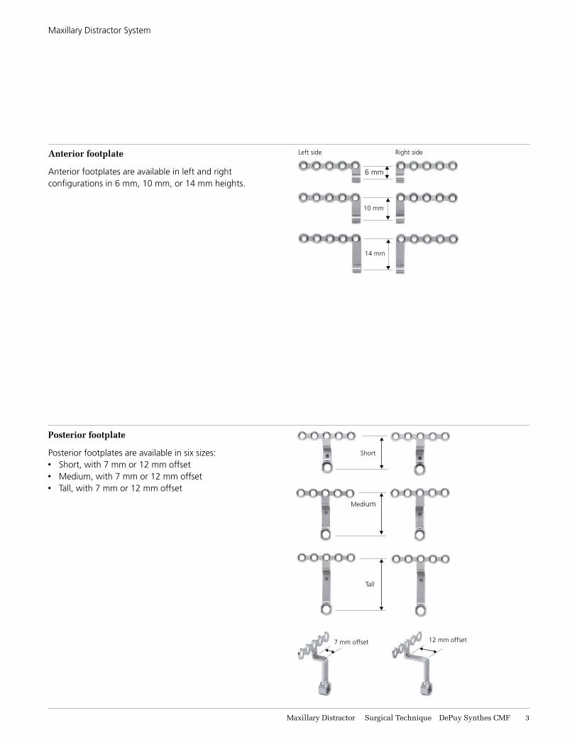
Anterior footplate
anterior footplates are available in left and right configurations in 6 mm, 10 mm, or 14 mm heights.
Posterior footplate
Posterior footplates are available in six sizes:x Short, with 7 mm or 12 mm offsetx medium, with 7 mm or 12 mm offsetx tall, with 7 mm or 12 mm offset
left side right side
14 mm
Short
7 mm offset
tall
12 mm offset
6 mm
10 mm
medium

4 DePuy Synthes CMF Maxillary Distractor Surgical Technique
the maxillary distractor is intended for use in craniofacial surgery, reconstructive procedures, and selective orthognathic surgery of the maxilla. Specifically, it is intended for distraction of the maxilla utilizing a lefort I osteotomy in adult and pediatric populations.
IndIcatIonS
these devices are intended for single use only and are offered nonSterIle only.
MR INFORMATIONthis device has not been evaluated for safety and compatibility in the mr environment. this device has not been tested for heating or migration in the mr environment.

Maxillary Distractor Surgical Technique DePuy Synthes CMF 5
PreoPeratIve PlannIng
Several preoperative investigations are useful in the planning of distractor position and alignment. ct scans, cephalometric tracings, dental models, and 3-d anatomical models are beneficial in determining the location of the osteotomy and placement of the devices. footplates can either be attached to the zygoma and maxilla or the zygoma and a dental splint.
ct scans and clinical assessments identify the nature of the craniofacial anomaly. If done using a specific scanning technique, a 3-d anatomical model can be developed (figure 1).
cephalometric tracings assist in identifying the extent of the deformity, and aid in planning the position of the distraction device to obtain the proper vector of advancement (figure 2).
dental models in conjunction with the clinical exam and cephalometric tracings, aid in the determination of the vector and the extent of movement required to correct the deformity (figure 3).
3-d anatomical models have been used as successful hands-on tools for contouring the footplates, aligning the distractors, and making the osteotomy prior to surgery. they also aid in documenting the preoperative condition of the patient. If a 3-d model is not attainable, bending of the footplates can be achieved intraoperatively (figure 4).
Precaution: Do not activate the distractors during model surgery, as the distractors are designed for a single activation cycle only. Activation beyond one cycle could cause the distractors to bind.
figure 1
figure 3 figure 4
figure 2

6 DePuy Synthes CMF Maxillary Distractor Surgical Technique
dIStractor aSSembly for maxIllary fIxatIon
2Choose anterior footplate
choose the anterior footplate size according to the treatment plan, giving specific consideration to the patient’s anatomy and screw placement.
1Choose distractor body
choose the proper length distractor body according to the planned amount of distraction.
Note: During the distraction process, the distractor body will remain in a fixed position while the soft tissue advances with the maxilla toward the front of the distractor body. To ensure the soft tissue does not obstruct the engagement of the activation screwdriver and the activation hex, the next longer size distractor body may be used.
left side
6 mm
10 mm
14 mm
right side

Maxillary Distractor Surgical Technique DePuy Synthes CMF 7
distractor assembly for maxillary fixation
3Insert anterior footplate
Insert the anterior footplate into the back of the distractor body. ensure that the screw holes are superior to the distractor body for attachment to the maxilla. turn the activation hex counterclockwise to engage the anterior footplate. (right assembly shown.)
Note: When the distractor is fully assembled, the slot on the distractor body must face medially while the countersinks of the screw holes on the anterior footplate must face laterally.
4Choose posterior footplate
choose the posterior footplate size according to the treatment plan, giving specific consideration to the patient’s anatomy and screw placement.
7 mm offset 12 mm offset
Short
tall
medium
8 DePuy Synthes CMF Maxillary Distractor Surgical Technique
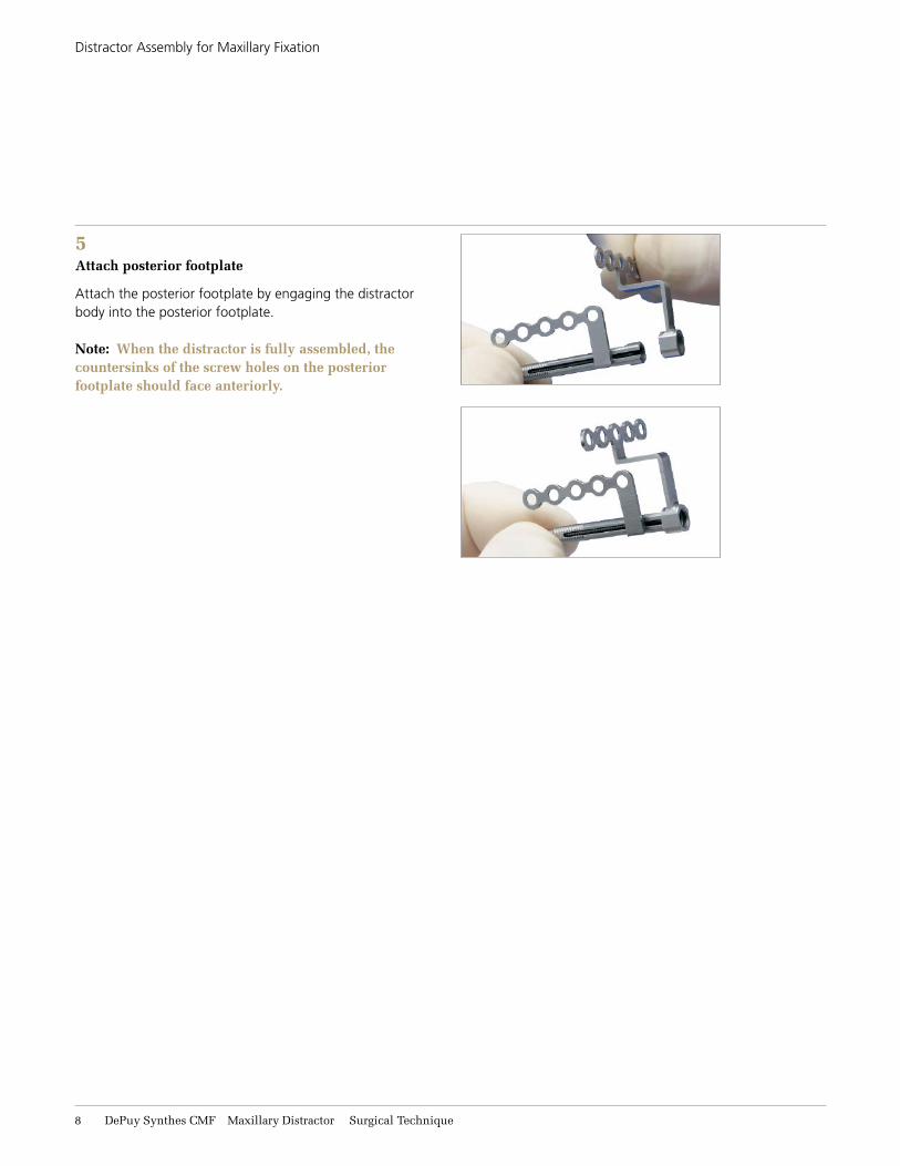
5Attach posterior footplate
attach the posterior footplate by engaging the distractor body into the posterior footplate.
Note: When the distractor is fully assembled, the countersinks of the screw holes on the posterior footplate should face anteriorly.
distractor assembly for maxillary fixation

Maxillary Distractor Surgical Technique DePuy Synthes CMF 9
6Insert machine screw
Instrument
313.925 2.4 mm Screwdriver, self-retaining
using the 2.4 mm screwdriver, insert the 3.5 mm machine screw through the posterior footplate and into the distractor body, locking the construct together. verify that the machine screw is fully seated in the distractor. (right assembly shown.)
Note: Once the distractor is fully assembled, ensure that the anterior footplate is in the “home” position by turning the activation hex clockwise until the anterior footplate meets the posterior footplate.
7Repeat steps 1 through 6 for the left assembly.
distractor assembly for maxillary fixation
11 DePuy Synthes CMF Maxillary Distractor Surgical Technique
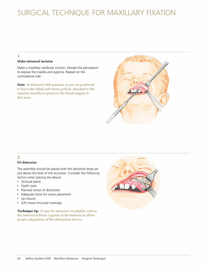
2Fit distractor
the assembly should be placed with the distractor body set just above the level of the occlusion. consider the following factors when placing the device: x occlusal planex tooth rootsx Planned vector of distractionx adequate bone for screw placementx lip closurex Soft tissue (mucosa) coverage
Technique tip: It may be necessary to slightly reduce the anterior-inferior zygoma at the buttress to allow proper adaptation of the distraction device.
SurgIcal technIque for maxIllary fIxatIon
1Make intraoral incision
make a maxillary vestibular incision. elevate the periosteum to expose the maxilla and zygoma. repeat on the contralateral side.
Note: In bilateral cleft patients, it may be preferred to leave the labial soft tissue pedicle attached to the anterior maxilla to preserve the blood supply to this area.

Maxillary Distractor Surgical Technique DePuy Synthes CMF 11
Surgical technique for maxillary fixation
Optional technique
Instrument
395.101 alignment rod, for maxillary distractor
the alignment rods may be used throughout the course of the surgery to:x aid in the parallel placement of the device;x Indicate vectors of advancement;x hold the distractors during screw placement.
Warning: The alignment rods should not be used as leverage for bending the footplates as this may cause damage to the distractor bodies.
Technique tips: • While parallel placement of the distractors would
be ideal, from a practical standpoint this may traumatize the buccal soft tissue and cause discomfort to the patient. A slight convergence of the distraction vectors is acceptable to ensure patient comfort.
• The point of convergence should be farther from the patient in larger maxillary advancements and can be closer to the patient in smaller maxillary advancements.
not preferableIdeal acceptable
12 DePuy Synthes CMF Maxillary Distractor Surgical Technique
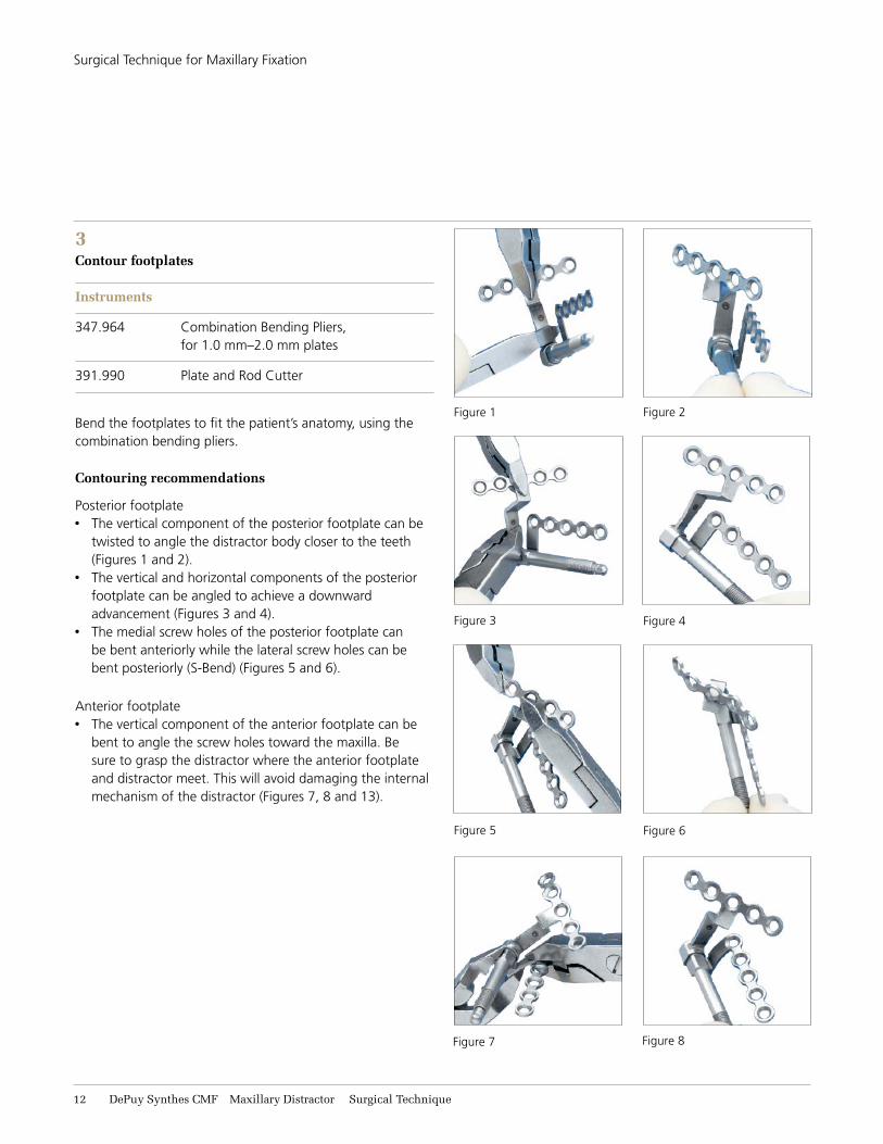
3Contour footplates
Instruments
347.964 combination bending Pliers, for 1.0 mm–2.0 mm plates
391.990 Plate and rod cutter
bend the footplates to fit the patient’s anatomy, using the combination bending pliers.
Contouring recommendations
Posterior footplatex the vertical component of the posterior footplate can be
twisted to angle the distractor body closer to the teeth (figures 1 and 2).
x the vertical and horizontal components of the posterior footplate can be angled to achieve a downward advancement (figures 3 and 4).
x the medial screw holes of the posterior footplate can be bent anteriorly while the lateral screw holes can be bent posteriorly (S-bend) (figures 5 and 6).
anterior footplatex the vertical component of the anterior footplate can be
bent to angle the screw holes toward the maxilla. be sure to grasp the distractor where the anterior footplate and distractor meet. this will avoid damaging the internal mechanism of the distractor (figures 7, 8 and 13).
Surgical technique for maxillary fixation
figure 1 figure 2
figure 3 figure 4
figure 5 figure 6
figure 7 figure 8
Maxillary Distractor Surgical Technique DePuy Synthes CMF 13
Surgical technique for maxillary fixation
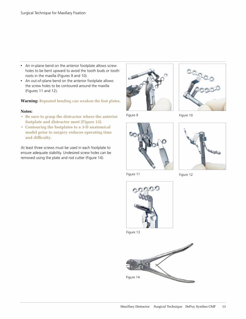
x an in-plane bend on the anterior footplate allows screw holes to be bent upward to avoid the tooth buds or tooth roots in the maxilla (figures 9 and 10).
x an out-of-plane bend on the anterior footplate allows the screw holes to be contoured around the maxilla (figures 11 and 12).
Warning: Repeated bending can weaken the foot plates.
Notes: • Be sure to grasp the distractor where the anterior
footplate and distractor meet (Figure 13).• Contouring the footplates to a 3-D anatomical
model prior to surgery reduces operating time and difficulty.
at least three screws must be used in each footplate to ensure adequate stability. undesired screw holes can be removed using the plate and rod cutter (figure 14).
figure 9 figure 10
figure 11 figure 12
figure 13
figure 14

14 DePuy Synthes CMF Maxillary Distractor Surgical Technique
4Mark distractor location
Instruments
311.03 handle, with mini quick coupling
314.67 1.5 mm/2.0 mm cruciform Screwdriver blade, with holding sleeve, short
317.72 1.5 mm drill bit, Stryker J-latch, with 12 mm stop
Place the assembly in the predetermined location. using the 1.5 mm drill bit, drill one hole through the posterior footplate and insert the desired length 2.0 mm screw into the zygoma. next, drill one hole through the anterior footplate and insert the desired length 2.0 mm screw into the maxilla.
Note: These screws should not be fully tightened, as they will be removed prior to performing the osteotomy.
Precautions:• Drill rate should never exceed 1,800 rpm. Higher
rates can result in thermal necrosis of the bone, soft tissue burns, and an oversized hole to be drilled. The adverse effects of an oversized hole include reduced pullout force, increased ease of the screws stripping in bone, and/or suboptimal fixation.
• Always irrigate during drilling.• Avoid drilling over nerve or tooth roots.• Take care while drilling as to not damage, entrap,
or tear a patient’s soft tissue or damage critical structures. Be sure to keep drill clear of loose surgical materials.
• Handle devices with care and dispose worn bone cutting instruments in a sharps container.
Surgical technique for maxillary fixation
Maxillary Distractor Surgical Technique DePuy Synthes CMF 15
5Repeat steps 2 through 4 on the contralateral side
use the alignment rods to verify the distractors are parallel to the desired vectors of advancement.
Surgical technique for maxillary fixation
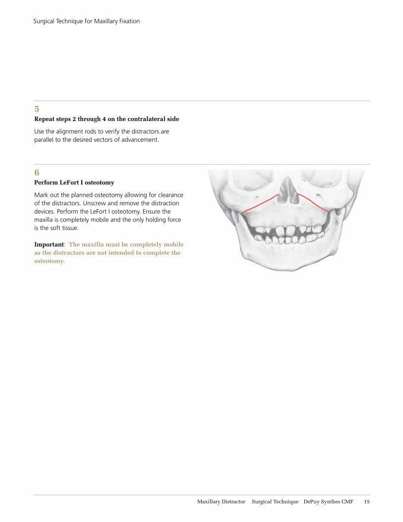
6Perform LeFort I osteotomy
mark out the planned osteotomy allowing for clearance of the distractors. unscrew and remove the distraction devices. Perform the lefort I osteotomy. ensure the maxilla is completely mobile and the only holding force is the soft tissue.
Important: The maxilla must be completely mobile as the distractors are not intended to complete the osteotomy.

16 DePuy Synthes CMF Maxillary Distractor Surgical Technique
7Reattach distractors
Instruments
311.03 handle, with mini quick coupling
314.67 1.5 mm/2.0 mm cruciform Screwdriver blade, with holding sleeve, short
317.72 1.5 mm drill bit, Stryker J-latch, with 12 mm stop
once the osteotomy is complete, reattach the distractors on both sides by aligning the footplates with previously drilled holes. reinsert the screws in the posterior and anterior footplates. drill and place the remaining screws in the desired locations. fully tighten all screws.
Notes: • One or both of the holes (A) and (B) on the
anterior footplate must contain a screw.• Please see Page 14 for Precautions for Drill Bits.
a minimum of three screws must be placed in each footplate for adequate stability.
Technique tip: Once the distractors are attached, use the alignment rods to verify that the vectors of advancement have not changed.
a b
Surgical technique for maxillary fixation

Maxillary Distractor Surgical Technique DePuy Synthes CMF 17
Surgical technique for maxillary fixation
8Confirm device stability and activation
Instrument
314.404 activation Instrument, 2.8 mm hex
using the activation instrument, turn each distractor in a counterclockwise direction, as marked on the screwdriver’s handle, to confirm the stability of the distractor. the maxilla will advance upon activation of the distractors. before closure, return each device to its original position.
Technique tip: Silicone tip guards can be inserted over the activation end of the distractor body to help prevent soft tissue irritation. The tip guards need to be removed in order for the distractor to be activated and can be reinserted after activation.

18 DePuy Synthes CMF Maxillary Distractor Surgical Technique
conSIderatIonS for dental SPlInt fIxatIon
Preparation of the dental splint before surgery
x the splint can be fabricated on dental models in the laboratory prior to surgery.
x mix the cold-cured acrylic powder and monomer solution according to the manufacturer’s instructions.
Considerations in splint design
x the occlusal surface, as well as the lateral surfaces of the splint, should be parallel to the vectors of distraction.
x Splint thickness must be a minimum of 5 mm in order to place the fixation screws.
x the lateral surfaces of the splint should have minimal projection (no more than 2 mm), and should allow for placement of screws without contacting teeth.
x the occlusal surface should be smooth to prevent interference with the mandibular teeth during distraction.

Maxillary Distractor Surgical Technique DePuy Synthes CMF 19
dIStractor aSSembly for dental SPlInt fIxatIon
2Choose anterior footplate
choose the anterior footplate size according to the treatment plan, giving specific consideration to the patient’s anatomy and screw placement on the dental splint.
1Choose distractor body
choose the proper length distractor body according to the planned amount of distraction.
Note: During the distraction process, the distractor body will remain in a fixed position while the soft tissue advances with the maxilla toward the front of the distractor body. To ensure the soft tissue does not obstruct the engagement of the activation screwdriver and the activation hex, the next longer size distractor body may be used.
left side right side
14 mm
6 mm
10 mm
21 DePuy Synthes CMF Maxillary Distractor Surgical Technique
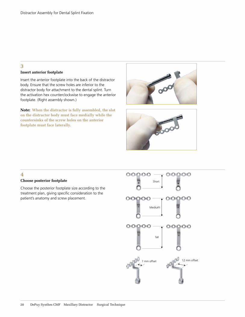
3Insert anterior footplate
Insert the anterior footplate into the back of the distractor body. ensure that the screw holes are inferior to the distractor body for attachment to the dental splint. turn the activation hex counterclockwise to engage the anterior footplate. (right assembly shown.)
Note: When the distractor is fully assembled, the slot on the distractor body must face medially while the countersinks of the screw holes on the anterior footplate must face laterally.
4Choose posterior footplate
choose the posterior footplate size according to the treatment plan, giving specific consideration to the patient’s anatomy and screw placement.
Short
7 mm offset
tall
12 mm offset
medium
distractor assembly for dental Splint fixation
Maxillary Distractor Surgical Technique DePuy Synthes CMF 21
dIStractor aSSembly for dental SPlInt fIxatIon
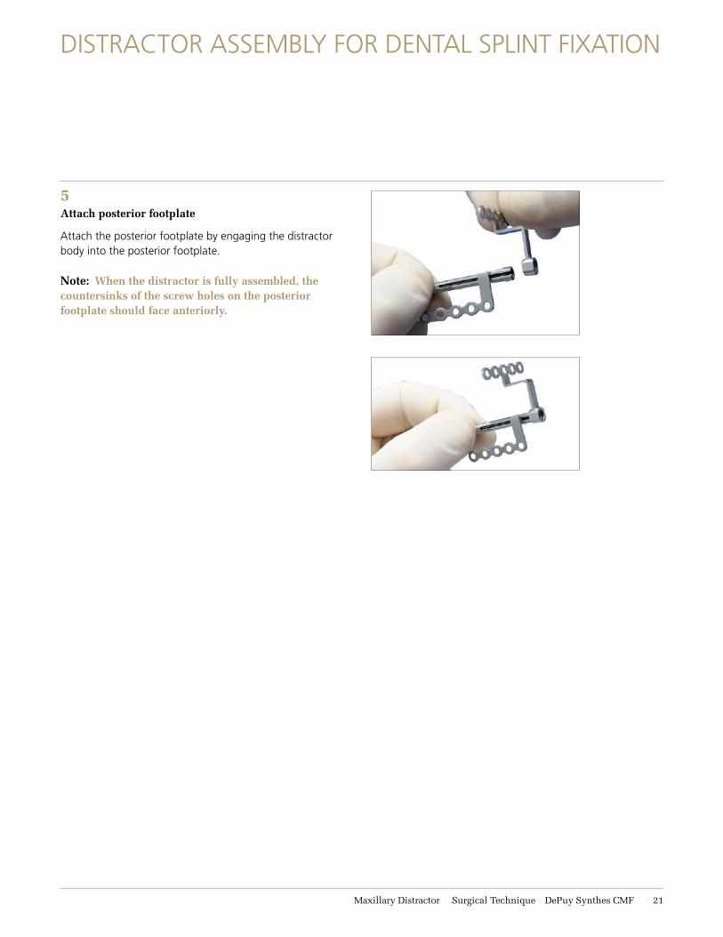
5Attach posterior footplate
attach the posterior footplate by engaging the distractor body into the posterior footplate.
Note: When the distractor is fully assembled, the countersinks of the screw holes on the posterior footplate should face anteriorly.

22 DePuy Synthes CMF Maxillary Distractor Surgical Technique
6Insert machine screw
Instrument
313.9252.4 mm Screwdriver, self-retaining
using the 2.4 mm screwdriver, insert the 3.5 mm machine screw through the posterior footplate and into the distractor body, locking the construct together. verify that the machine screw is fully seated in the distractor. (right assembly shown.)
Note: Once the distractor is fully assembled, ensure that the anterior footplate is in the “home” position by turning the activation hex clockwise until the anterior footplate meets the posterior footplate.
7Repeat steps 1 through 6 for the left assembly.
distractor assembly for dental Splint fixation
Maxillary Distractor Surgical Technique DePuy Synthes CMF 23
SurgIcal technIque for dental SPlInt fIxatIon
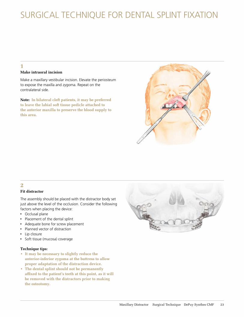
1Make intraoral incision
make a maxillary vestibular incision. elevate the periosteum to expose the maxilla and zygoma. repeat on the contralateral side.
Note: In bilateral cleft patients, it may be preferred to leave the labial soft tissue pedicle attached to the anterior maxilla to preserve the blood supply to this area.
2Fit distractor
the assembly should be placed with the distractor body set just above the level of the occlusion. consider the following factors when placing the device: x occlusal planex Placement of the dental splintx adequate bone for screw placementx Planned vector of distractionx lip closurex Soft tissue (mucosa) coverage
Technique tips: • It may be necessary to slightly reduce the
anterior-inferior zygoma at the buttress to allow proper adaptation of the distraction device.
• The dental splint should not be permanently affixed to the patient’s teeth at this point, as it will be removed with the distractors prior to making the osteotomy.
24 DePuy Synthes CMF Maxillary Distractor Surgical Technique
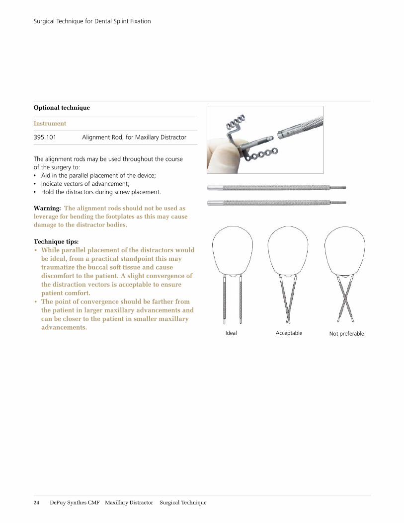
Optional technique
Instrument
395.101 alignment rod, for maxillary distractor
the alignment rods may be used throughout the course of the surgery to:x aid in the parallel placement of the device;x Indicate vectors of advancement;x hold the distractors during screw placement.
Warning: The alignment rods should not be used as leverage for bending the footplates as this may cause damage to the distractor bodies.
Technique tips: • While parallel placement of the distractors would
be ideal, from a practical standpoint this may traumatize the buccal soft tissue and cause discomfort to the patient. A slight convergence of the distraction vectors is acceptable to ensure patient comfort.
• The point of convergence should be farther from the patient in larger maxillary advancements and can be closer to the patient in smaller maxillary advancements.
not preferableIdeal acceptable
Surgical technique for dental Splint fixation

Maxillary Distractor Surgical Technique DePuy Synthes CMF 25
Surgical technique for dental Splint fixation
3Contour footplates
Instruments
347.964 combination bending Pliers, for 1.0 mm–2.0 mm Plates
391.990 Plate and rod cutter
bend the footplates to fit the patient’s anatomy, using the combination bending pliers.
Contouring recommendationsPosterior footplatesx the vertical component of the posterior footplate can be
twisted to angle the distractor body closer to the teeth (figures 1 and 2).
– the vertical and horizontal components of the posterior footplate can be angled to achieve a downward advancement (figures 3 and 4).
– the medial screw holes of the posterior footplate can be bent anteriorly while the lateral screw holes can be bent posteriorly (S-bend) (figures 5 and 6).
anterior footplatex the vertical component of the anterior footplate can be
bent to angle the screw holes toward the dental splint. be sure to grasp the distractor where the anterior footplate and distractor meet. this will avoid damaging the internal mechanism of the distractor (figures 7, 8 and 11).
figure 1 figure 2
figure 3 figure 4
figure 5 figure 6
figure 7 figure 8
26 DePuy Synthes CMF Maxillary Distractor Surgical Technique
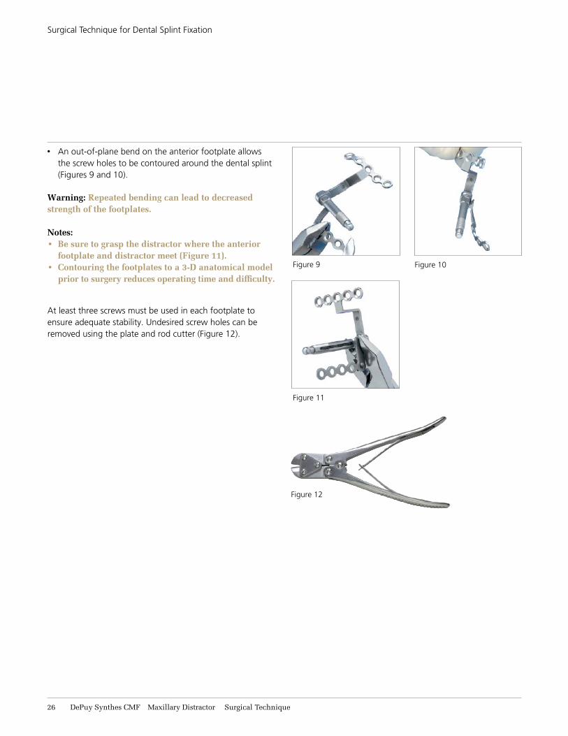
x an out-of-plane bend on the anterior footplate allows the screw holes to be contoured around the dental splint (figures 9 and 10).
Warning: Repeated bending can lead to decreased strength of the footplates.
Notes:• Be sure to grasp the distractor where the anterior
footplate and distractor meet (Figure 11).• Contouring the footplates to a 3-D anatomical model
prior to surgery reduces operating time and difficulty.
at least three screws must be used in each footplate to ensure adequate stability. undesired screw holes can be removed using the plate and rod cutter (figure 12).
figure 9 figure 10
figure 11
figure 12
Surgical technique for dental Splint fixation

Maxillary Distractor Surgical Technique DePuy Synthes CMF 27
Surgical technique for dental Splint fixation
4Mark distractor location
Instruments
311.03 handle, with mini quick coupling
314.67 1.5 mm/2.0 mm cruciform Screwdriver blade, with holding sleeve, short
317.72 1.5 mm drill bit, Stryker J-latch, with 12 mm stop
Place the assembly in the predetermined location. using the 1.5 mm drill bit, drill one hole through the posterior footplate and insert the desired length 2.0 mm screw into the zygoma. next, drill two holes through the anterior footplate and insert the desired length 2.0 mm screws into the dental splint.
Notes: • The screw in the posterior footplate should not
be fully tightened, as it will be removed prior to performing the osteotomy. The two screws in the anterior footplate can be fully tightened.
Precautions:• Drill rate should never exceed 1,800 rpm. Higher
rates can result in thermal necrosis of the bone, soft tissue burns, and an oversized hole to be drilled. The adverse effects of an oversized hole include reduced pullout force, increased ease of the screws stripping in bone, and/or suboptimal fixation.
• Always irrigate during drilling.• Avoid drilling over nerve or tooth roots.• Take care while drilling as to not damage, entrap,
or tear a patient’s soft tissue or damage critical structures. Be sure to keep drill clear of loose surgical materials.
• Handle devices with care and dispose worn bone cutting instruments in a sharps container.
28 DePuy Synthes CMF Maxillary Distractor Surgical Technique
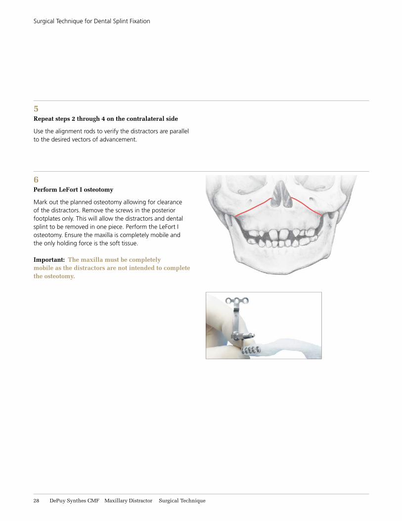
6Perform LeFort I osteotomy
mark out the planned osteotomy allowing for clearance of the distractors. remove the screws in the posterior footplates only. this will allow the distractors and dental splint to be removed in one piece. Perform the lefort I osteotomy. ensure the maxilla is completely mobile and the only holding force is the soft tissue.
Important: The maxilla must be completely mobile as the distractors are not intended to complete the osteotomy.
5Repeat steps 2 through 4 on the contralateral side
use the alignment rods to verify the distractors are parallel to the desired vectors of advancement.
Surgical technique for dental Splint fixation

Maxillary Distractor Surgical Technique DePuy Synthes CMF 29
7Reattach distractors
Instruments
311.03 handle, with mini quick coupling
314.67 1.5 mm/2.0 mm cruciform Screwdriver blade, with holding sleeve, short
317.72 1.5 mm drill bit, Stryker J-latch, with 12 mm stop
once the osteotomy is complete, realign the distractors and dental splint with the previously drilled holes in the zygoma. affix the dental splint to the patient’s teeth with arch bar wiring, interdental wiring, circummaxillary wiring, or wiring to orthodontic brackets. reinsert the screws in the posterior footplates. drill and place the remaining screws in the desired locations. fully tighten all screws.
Notes: • One or both of the holes (A) and (B) on the
anterior footplate must contain a screw.• Please see Page 27 for Precautions for Drill Bits.
a minimum of three screws must be placed in each footplate for adequate stability.
Technique tip: Once the distractors are attached, use the alignment rods to verify that the vectors of advancement have not changed.
Surgical technique for dental Splint fixation
a b

31 DePuy Synthes CMF Maxillary Distractor Surgical Technique
8Confirm device stability and activation
Instrument
314.404 activation Instrument, 2.8 mm hex
using the activation instrument, turn each distractor in a counterclockwise direction, as marked on the screwdriver’s handle, to confirm the stability of the distractor. the maxilla will advance upon activation of the distractors. before closure, return each device to its original position.
Technique tip: Silicone tip guards can be inserted over the activation end of the distractor body to help prevent soft tissue irritation. The tip guards need to be removed in order for the distractor to be activated and can be reinserted after activation.
Surgical technique for dental Splint fixation

Maxillary Distractor Surgical Technique DePuy Synthes CMF 31
PoStoPeratIve conSIderatIonS
Suggested distraction protocol
distraction should begin four to six days after device placement. to achieve lengthening, engage the activation hex with the activation instrument and rotate counterclock-wise (in direction of arrow marked on the instrument).
each complete rotation equals 0.5 mm of distraction. It is recommended to perform one turn twice a day, or alternatively, a half turn four times a day if the patient experiences pain or discomfort.
Note: A rate of 1.0 mm of distraction per day is recommended to prevent premature consolidation.
Document progress
distraction progress should be observed by documenting the changes in the anterior maxillary and mandibular occlusion. a Patient care guide is included with the activation instrument to help record and monitor distraction progress.
Note: The patient should be advised on maintaining good oral hygiene during all phases of treatment.
activation instrument
Daily Instructions
Place the activation instrument on the end of the distractor. Be certain that the activation instrument fits securely over the end of the distractor.
Turn the activation instrument as instructed by your physician below. Please note that it is important to only turn the activation instrument in the direction of the arrow marked on the handle. Turning the activation instrument in the wrong direction (opposite of arrow) can interfere with the distraction process.
Patient’s left side:
_____ full turn(s) _____ time(s) per day
Patient’s right side:
_____ full turn(s) _____ time(s) per day
Dear Patient,
You have been fitted with distractors to aid in the lengthening of your upper jaw. Distraction is an ongoing procedure which requires daily activation of the distractors with a special instrument called an activation instrument. Under instruction from your physician, you may need to activate the distractors multiple times each day.
Please follow the instructions within this guide. If you have questions or concerns, or if any redness, drainage or excess pain occurs during activation, contact your physician.
© 2002 Synthes, Inc. or its affiliates. All rights reserved. Synthes is a trademark of Synthes, Inc. or its affiliates. Printed in U.S.A. 8/09 J3997-B GP2046-B
Note: Distractor position may vary according to individualized treatment needs.
www.synthes.com
PATIenT CAre GUIDeFor the Maxillary Distractor
Daily Instructions
32 DePuy Synthes CMF Maxillary Distractor Surgical Technique
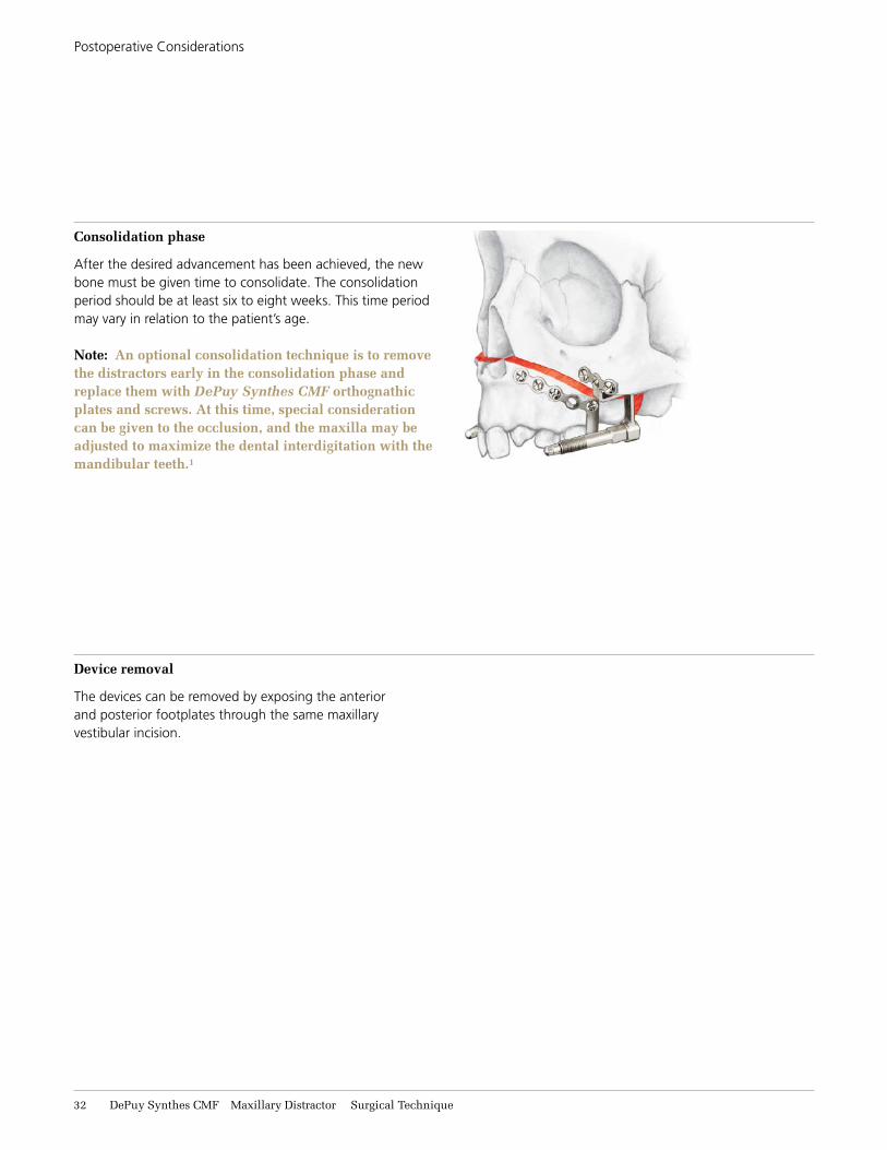
Consolidation phase
after the desired advancement has been achieved, the new bone must be given time to consolidate. the consolidation period should be at least six to eight weeks. this time period may vary in relation to the patient’s age.
Note: An optional consolidation technique is to remove the distractors early in the consolidation phase and replace them with DePuy Synthes CMF orthognathic plates and screws. At this time, special consideration can be given to the occlusion, and the maxilla may be adjusted to maximize the dental interdigitation with the mandibular teeth.1
Device removal
the devices can be removed by exposing the anterior and posterior footplates through the same maxillary vestibular incision.
Postoperative considerations
Maxillary Distractor Surgical Technique DePuy Synthes CMF 33
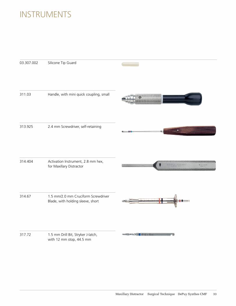
311.03 handle, with mini quick coupling, small
313.925 2.4 mm Screwdriver, self-retaining
314.404 activation Instrument, 2.8 mm hex, for maxillary distractor
314.67 1.5 mm/2.0 mm cruciform Screwdriver blade, with holding sleeve, short
03.307.002 Silicone tip guard
InStrumentS
317.72 1.5 mm drill bit, Stryker J-latch, with 12 mm stop, 44.5 mm

34 DePuy Synthes CMF Maxillary Distractor Surgical Technique
347.964 combination bending Pliers, for 1.0 mm/2.0 mm plates
391.990 Plate and rod cutter
395.101 alignment rod, for maxillary distractor
Instruments

Maxillary Distractor Surgical Technique DePuy Synthes CMF 35
maxIllary dIStractor Set (115.628)
Modules and Trays304.686 Instrument tray, universal
304.687 Instrument tray lid, universal
304.753 maxillary distractor module case
Instruments03.307.002 Silicone tip guard, 2 ea
Screw length markers (10/pkg)
304.104 4 mm
304.106 6 mm
304.108 8 mm
304.110 10 mm
311.03 handle, with mini quick coupling, small, 2 ea
313.925 2.4 mm Screwdriver, self-retaining
314.404 activation Instrument, 2.8 mm hex, for maxillary distractor, 2 ea
314.67 1.5 mm/2.0 mm cruciform Screwdriver blade, with holding sleeve, short, 2 ea
317.72 1.5 mm drill bit, Stryker J-latch, with 12 mm stop, 44.5 mm, 2 ea
347.964 combination bending Pliers, for 1.0 mm/2.0 mm plates, 2 ea
391.990 Plate and rod cutter
395.101 alignment rod, for maxillary distractor, 4 ea
Implants2.0 mm cortex Screws, self-tapping
length (mm) qty201.804.98 4 10201.806.98 6 20201.808.98 8 20201.810.98 10 10
2.4 mm cortex Screws, self-tapping, 5 ea (for use as emergency screws)
length (mm) 201.506 6 201.508 8 201.510 10
for detailed cleaning and sterilization instructions, please refer to: www.synthes.com/cleaning-sterilization In canada, the cleaning and sterilization instructions will be provided with the loaner shipments.

36 DePuy Synthes CMF Maxillary Distractor Surgical Technique
maxillary distractor bodies, 4 ea length (mm)
288.025 10288.026 15288.027 20288.028 25
anterior footplates, for maxillary distractor, maxilla right/splint left, 2 ea height (mm)
288.038 6288.039 10288.040 14
anterior footplates, for maxillary distractor, maxilla left/splint right, 2 ea height (mm)288.042 6288.043 10288.044 14
Posterior footplates, for maxillary distractor, 4 ea offset (mm)
288.052 7 short288.053 12 short288.055 7 medium288.056 12 medium288.058 7 tall288.059 12 tall
288.065 3.5 mm machine Screw, for maxillary distractor, 4 ea
Instruments

Maxillary Distractor Surgical Technique DePuy Synthes CMF 37
reference
1 Jeffery Weinzweig, Scott bartlett, et al. “Immediate versus delayed midface distraction in a Primate model using a new Intraoral Internal device.” Plastic and Reconstructive Surgery. 109 no 5 (2002): x1609.

Manufactured by (United States):Synthes USA Products, LLC1302 Wrights lane eastWest chester, Pa 19380 telephone: (610) 719-5000 to order: (800) 523-0322 fax: (610) 251-9056
www.depuysynthes.com
© dePuy Synthes cmf, a division of doI 2014. all rights reserved. dSuS/cmf/0914/0203 11/14 dv
Some devices listed in this Technique Guide may not have been licensed in accordance with Canadian Law and may not be for sale in Canada. Please contact your Sales Consultant for items approved for sale in Canada.
Limited Warranty and Disclaimer: DePuy Synthes CMF products are sold with a limited warranty to the original purchaser against defects in workmanship and materials. Any other express or implied warranties, including warranties of merchantability or fitness, are hereby disclaimed.
WARNING: In the USA, this product has labeling limitations. See package insert for complete information.
Rx Only
not all products are currently available in all markets.
Legal Manufacturer (Canada):Synthes (Canada) Ltd. 2566 meadowpine boulevard mississauga, ontario l5n 6P9 telephone: (905) 567-0440 to order: (800) 668-1119 fax: (905) 567-3185