Max Flow: 170 gpm (644 lpm) LOW PRESSURE FILTERS · LOW PRESSURE FILTERS FIK Max Flow: 170 gpm (644...
10
64 • Hydraulic Filtration LOW PRESSURE FILTERS www.donaldson.com FIK Max Flow: 170 gpm (644 lpm) FIK In-Tank Filters Features FIK in-tank filters are economical, space-saving units offering a variety of options including aluminum or plastic access covers, mounting option, breathers and accessories including diffusers and oil dipsticks. FIK filters, featuring a die-cast aluminum head and a steel or plastic canister are designed to handle heavy-duty applications. The head (and the inlet) sit above the tank, while the housing remains inside the tank, offering design-in flexibility. Optional air breather featuring T.R.A.P.™ technology are available with style A and B, designed to allow the breather to be mounted directly in the FIK filter head, thus eliminating the cost associated with an additional penetration to the hydraulic tank for breather installation. FIK filters offer three service indicators to choose from: pressure gauge, visual indicator and electrical indicator. FIK filter assemblies are shipped from the factory with cellulose or Synteq™ synthetic filter media, and replacement cartridges are offered in a range of media types and performance ratings. STYLE A STYLE B STYLE C STYLE D STYLE E Working Pressures to: 145 psi 1000 kPa 10 bar Rated Static Burst to: 217 psi 1500 kPa 15 bar Flow Range to: 170 gpm 644 lpm Beta Rating Standard Bypass Ratings • Performance to ß 8(c) =1000 • 22 psi / 150 kPa / 1.5 bar Porting Size Options Operating Temperatures • ½", ¾", 1" NPT • -4°F to 194°F / -20°C to 90°C • SAE-8, SAE-12, SAE-16, SAE-20, SAE-24 O-ring Collapse Ratings • 2" SAE 4-Bolt Flange Code 61 • 145 psid / 1000 kPa / 10 bar
Transcript of Max Flow: 170 gpm (644 lpm) LOW PRESSURE FILTERS · LOW PRESSURE FILTERS FIK Max Flow: 170 gpm (644...

64 • Hydraulic Filtration
LOW
PRE
SSUR
E FI
LTER
S
www.donaldson.com
FIKMax Flow: 170 gpm (644 lpm)
FIK In-Tank Filters
FeaturesFIK in-tank filters are economical, space-saving units offering a variety of options including aluminum or plastic access covers, mounting option, breathers and accessories including diffusers and oil dipsticks. FIK filters, featuring a die-cast aluminum head and a steel or plastic canister are designed to handle heavy-duty applications. The head (and the inlet) sit above the tank, while the housing remains inside the tank, offering design-in flexibility. Optional air breather featuring T.R.A.P.™ technology are available with style A and B, designed to allow the breather to be mounted directly in the FIK filter head, thus eliminating the cost associated with an additional penetration to the hydraulic tank for breather installation. FIK filters offer three service indicators to choose from: pressure gauge, visual indicator and electrical indicator. FIK filter assemblies are shipped from the factory with cellulose or Synteq™ synthetic filter media, and replacement cartridges are offered in a range of media types and performance ratings.
STYLE ASTYLE B
STYLE CSTYLE D
STYLE E
Working Pressures to:
145 psi 1000 kPa10 bar
Rated Static Burst to:
217 psi1500 kPa15 bar
Flow Range to:
170 gpm644 lpm
Beta Rating Standard Bypass Ratings
• Performance to ß8(c)
=1000 • 22 psi / 150 kPa / 1.5 bar
Porting Size Options Operating Temperatures
• ½", ¾", 1" NPT • -4°F to 194°F / -20°C to 90°C
• SAE-8, SAE-12, SAE-16, SAE-20, SAE-24 O-ring Collapse Ratings
• 2" SAE 4-Bolt Flange Code 61 • 145 psid / 1000 kPa / 10 bar

Hydraulic Filtration • 65
LOW PRESSURE FILTERS
www.donaldson.com
FIKMax Flow: 170 gpm (644 lpm)
Redesigned with Features for Application Flexibility, Improved Servicing and Enhanced Filtration Performance
T.R.A.P.™ Breather TechnologyBreather ordered separatelyPlug ships standard. Pressurized & atmospheric breathers available. • Quick fit connection
• Anti-splash design allows smooth operation under tilt conditions
• Keeps reservoir free from condensation
Service Indicator Ports• Electrical, visual or
pressure gauge options
Flexible Mounting Configurations2 or 4 hole mounting option • Better sealing and stability
• Enhanced stability on plastic tanks
• Reverse compatible – retrofit existing tanks with the new hole configuration
Multifunctional Ports(custom)Contact your Donaldson sales representative for details• Can be converted into
auxiliary inlet ports
• The two secondary inlet ports can be used in conjunction with the main inlet port for higher flow rates
Accessories (custom)Contact your Donaldson sales representative for details• Oil dipstick
• Diffuser
• Extension tube
Flat Gasket Design• For leak-tight operation
Built-In By-Pass Valve• New by-pass valve installed with
every filter replacement
Filter Media Technology Wide range of Donaldson media offerings – to meet various performance targets and cleanliness standards
Applications• Cooling Circuits• Fluid Conditioning Systems• Lube Oil Systems• Process Systems• Return Lines• Side Loop Systems
STYLE B Shown Below

66 • Hydraulic Filtration
LOW
PRE
SSUR
E FI
LTER
S
www.donaldson.com
FIK Max Flow: 170 gpm (644 lpm)
FIK Specification IllustrationsLow Flow Assemblies < 32 gpm (120 lpm)
STYLE AK030319
STYLE BK040811K040812K040813K041782
Improved Design Feature
• 2 or 4 hole mounting options• Built-in by-pass valve in the cartridge • Improved seal design • Anti-splash air flow path• Optional mini T.R.A.P. breather
Improved Design Feature
• 2 or 4 hole mounting options• Built-in by-pass valve in the cartridge • Improved seal design • Anti-splash air flow path• Optional mini T.R.A.P. breather• Multifunctional ports for accessories
Improved Design Feature
• Improved seal design • Built-in by-pass valve in the cartridge
High Flow Assemblies 5 - 170 gpm (18 - 643 lpm)
STYLE A STYLE B STYLE C, D, E
Ports for service
indicator
STYLE C, D, EAssembly part numbers on following page
Assembly - Side Views
Head - Top Views

Hydraulic Filtration • 67
LOW PRESSURE FILTERS
www.donaldson.com
Head - Top Views
FIK Max Flow: 170 gpm (644 lpm)
STYLE CK041770K041771K041772 K041773 K031027 (2 point mount only)
STYLE DK070248K071001K070249K071002
STYLE E K051204K052053
K041774K040799 K040798
K070250K071003
Dimensions
STYLE C STYLE D STYLE E
Improved Design Feature
• 2 or 4 hole mounting options
High Flow Assemblies 5 - 170 gpm (18 - 643 lpm)
Design Feature
• 4 hole mounting
Design Feature
• 3 hole mounting
Port for service indicator
Port for service indicator
Port for service indicator
ASSEMBLYDIMENSIONS
ASSEMBLY PART NUMBER
STYLE A STYLE B STYLE C STYLE D STYLE E
K030319 K040811 K040812K040813K041782
K0310272 pt mount only K041770
K041771K041772 K041773 K041774 K040799 K040798
K070248K071001
K070249K071002
K070250K071003
K051204K052053
mm in mm in mm in mm in mm in mm in mm in mm in mm in mm in mm in mm in
C 176.8 6.96 91.0 3.58 141.0 5.55 218.0 8.58 78.0 3.07 99.0 3.90 149.0 5.87 227.7 8.96 242.0 9.53 290.0 11.42 434.0 17.09 224.0 8.82
D 248.6 9.79 189.0 7.44 239.0 9.41 316.0 12.44 132.0 5.20 173.3 6.82 223.2 8.79 301.9 11.89 348.0 13.70 395.5 15.57 539.5 21.24 313.8 12.35S
SERVICE CLEARANCE
220.0 8.66 180.0 7.09 220.0 8.66 305.0 12.01 149.0 5.87 170.0 6.69 220.0 8.66 299.0 11.77 320.0 12.60 365.0 14.37 515.0 20.28 305.0 12.01
G 20.0 0.79 27.6 1.09 27.6 1.09 39.6 1.56 25.2 0.99 27.6 1.09 27.6 1.09 39.5 1.56 50.0 1.97 63.5 2.50 63.5 2.50 40.0 1.57B
TANK OPENING 57.0 2.24 90.0 3.54 90.0 3.54 90.0 3.54 68.6 2.70 90.0 3.54 90.0 3.54 90.0 3.54 175.0 6.89 175.0 6.89 175.0 6.89 131.0 5.16
H 49.7 1.96 70.5 2.78 70.5 2.78 70.5 2.78 49.0 1.93 68.0 2.68 68.0 2.68 68.0 2.68 120.0 4.72 126.0 4.96 126.0 4.96 95.0 3.74J 54.2 2.13 94.5 3.72 94.5 3.72 94.5 3.72 44.0 1.73 55.0 2.17 55.0 2.17 55.0 2.17 100.0 3.94 100.0 3.94 100.0 3.94 78.0 3.07K 23.0 0.91 32.0 1.26 32.0 1.26 32.0 1.26 22.0 0.87 29.5 1.16 29.5 1.16 29.5 1.16 41.0 1.61 48.5 1.91 48.5 1.91 35.0 1.38F
2 POINT MOUNT 11.0 0.43 11.0 0.43 11.0 0.43 11.0 0.43 Ø6.4 Ø0.25 8.5 0.33 8.5 0.33 8.5 0.33 N/A N/A N/A N/A N/A N/A N/A N/A
F1 Ø82 Ø3.23 Ø112 Ø4.41 Ø112 Ø4.41 Ø112 Ø4.41 90.0 3.54 9.5 0.37 9.5 0.37 9.5 0.37 N/A N/A N/A N/A N/A N/A N/A N/AF2 Ø90 Ø3.54 Ø116 Ø4.57 Ø116 Ø4.57 Ø116 Ø4.57 N/A N/A 115.0 4.53 115.0 4.53 115.0 4.53 N/A N/A N/A N/A N/A N/A N/A N/AN
3 POINT MOUNT N/A N/A N/A N/A N/A N/A N/A N/A N/A N/A N/A N/A N/A N/A N/A N/A N/A N/A N/A N/A N/A N/A Ø11 Ø0.43
N1 N/A N/A N/A N/A N/A N/A N/A N/A N/A N/A N/A N/A N/A N/A N/A N/A N/A N/A N/A N/A N/A N/A 45° 45°N2 N/A N/A N/A N/A N/A N/A N/A N/A N/A N/A N/A N/A N/A N/A N/A N/A N/A N/A N/A N/A N/A N/A 120° 120°N3 N/A N/A N/A N/A N/A N/A N/A N/A N/A N/A N/A N/A N/A N/A N/A N/A N/A N/A N/A N/A N/A N/A Ø175 Ø6.89E
4 POINT MOUNT 11.0 0.43 8.5 0.33 8.5 0.33 8.5 0.33 N/A N/A 9.0 0.35 9.0 0.35 9.0 0.35 Ø10.5 Ø0.41 Ø11 Ø0.43 Ø11 Ø0.43 N/A N/A
E1 Ø84 Ø3.31 Ø126 Ø4.96 Ø126 Ø4.96 Ø126 Ø4.96 N/A N/A Ø115 Ø4.53 Ø115 Ø4.53 Ø115 Ø4.53 30° 30° 30° 30° 30° 30° N/A N/AE2 Ø90 Ø3.54 Ø130 Ø5.12 Ø130 Ø5.12 Ø130 Ø5.12 N/A N/A Ø126 Ø4.96 Ø126 Ø4.96 Ø126 Ø4.96 90° 30° 90° 90° 90° 90° N/A N/AE3 N/A N/A N/A N/A N/A N/A N/A N/A N/A N/A N/A N/A N/A N/A N/A N/A Ø220 Ø8.66 Ø220 Ø8.66 Ø220 Ø8.66 N/A N/A
WEIGHT lbs kg lbs kg lbs kg lbs kg lbs kg lbs kg lbs kg lbs kg lbs kg lbs kg lbs kg lbs kg
K 1.8 0.8 2.1 0.95 3.2 1.45 4.1 1.86 1.1 0.5 1.8 0.8 2.1 0.95 2.43 1.1 10.0 4.5 13.1 5.9 18.6 8.4 7.0 3.2
68 • Hydraulic Filtration
LOW
PRE
SSUR
E FI
LTER
S
www.donaldson.com
FIK Max Flow: 170 gpm (644 lpm)
FIK Components
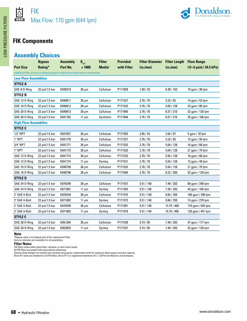
Assembly ChoicesBypass Assembly ß
x(c)Filter Provided Filter Diameter Filter Length Flow Range
Port Size Rating* Part No. = 1000 Media† with Filter (in./mm) (in./mm) (@~5 psid / 34.5 kPa)†additional filter choices on following pages to meet various performance requirements
Low Flow Assemblies STYLE ASAE-8 O-Ring 22 psi/1.5 bar K030319 36 µm Cellulose P171839 1.69 / 43 6.38 / 162 10 gpm / 38 lpm
STYLE BSAE-12 O-Ring 22 psi/1.5 bar K040811 36 µm Cellulose P171527 2.76 / 70 3.23 / 82 14 gpm / 53 lpm
SAE-16 O-Ring 22 psi/1.5 bar K040812 36 µm Cellulose P171533 2.76 / 70 5.04 / 128 23 gpm / 86 lpm
SAE-20 O-Ring 22 psi/1.5 bar K040813 36 µm Cellulose P171840 2.76 / 70 8.27 / 210 32 gpm / 120 lpm
SAE-20 O-Ring 22 psi/1.5 bar K041782 11 µm Synthetic P171846 2.76 / 70 8.27 / 210 28 gpm / 106 lpm
High Flow AssembliesSTYLE C1/2" NPT 22 psi/1.5 bar K031027 36 µm Cellulose P171503 2.05 / 52 2.64 / 67 5 gpm / 18 lpm
1" NPT 22 psi/1.5 bar K041770 36 µm Cellulose P171527 2.76 / 70 3.23 / 82 15 gpm / 56 lpm
3/4" NPT 22 psi/1.5 bar K041771 36 µm Cellulose P171533 2.76 / 70 5.04 / 128 18 gpm / 68 lpm
1" NPT 22 psi/1.5 bar K041772 36 µm Cellulose P171533 2.76 / 70 5.04 / 128 21 gpm / 79 lpm
SAE-12 O-Ring 22 psi/1.5 bar K041773 36 µm Cellulose P171533 2.76 / 70 5.04 / 128 18 gpm / 68 lpm
SAE-12 O-Ring 22 psi/1.5 bar K041774 11 µm Synteq P171531 2.76 / 70 5.04 / 128 13 gpm / 49 lpm
SAE-16 O-Ring 22 psi/1.5 bar K040799 36 µm Cellulose P171533 2.76 / 70 5.04 / 128 21 gpm / 79 lpm
SAE-16 O-Ring 22 psi/1.5 bar K040798 36 µm Cellulose P171840 2.76 / 70 8.22 / 209 32 gpm / 120 lpm
STYLE DSAE-24 O-Ring 22 psi/1.5 bar K070248 36 µm Cellulose P171557 5.51 / 140 7.49 / 203 66 gpm / 248 lpm
SAE-24 O-Ring 22 psi/1.5 bar K071001 11 µm Synteq P171555 5.51 / 140 7.49 / 203 44 gpm / 165 lpm
2" SAE 4-Bolt 22 psi/1.5 bar K070249 36 µm Cellulose P171575 5.51 / 140 9.84 / 250 106 gpm / 399 lpm
2" SAE 4-Bolt 22 psi/1.5 bar K071002 11 µm Synteq P171573 5.51 / 140 9.84 / 250 74 gpm / 278 lpm
2" SAE 4-Bolt 22 psi/1.5 bar K070250 36 µm Cellulose P171581 5.51 / 140 15.75 / 400 170 gpm / 643 lpm
2" SAE 4-Bolt 22 psi/1.5 bar K071003 11 µm Synteq P171579 5.51 / 140 15.75 / 400 120 gpm / 451 lpm
STYLE ESAE-20 O-Ring 22 psi/1.5 bar K051204 36 µm Cellulose P171539 3.74 / 95 7.49 / 203 47 gpm / 177 lpm
SAE-20 O-Ring 22 psi/1.5 bar K052053 11 µm Synteq P171537 3.74 / 95 7.49 / 203 32 gpm / 120 lpm
Note*Bypass valve is an integral part of the replacement filter.Service indicator port available for all assemblies.
Filter NotesFIK filters utilize either glass fiber, cellulose, or wire mesh media.All FIK filters are potted with polyurethane adhesives.Synteq media designs are double wire-backed using epoxy-coated steel mesh for maximum pleat support and dirt capacity.Buna-N® seals are standard on all FIK filters. Buna-N® is a registered trademark of E. I. DuPont de Nemours and Company.
Hydraulic Filtration • 69
LOW PRESSURE FILTERS
www.donaldson.com
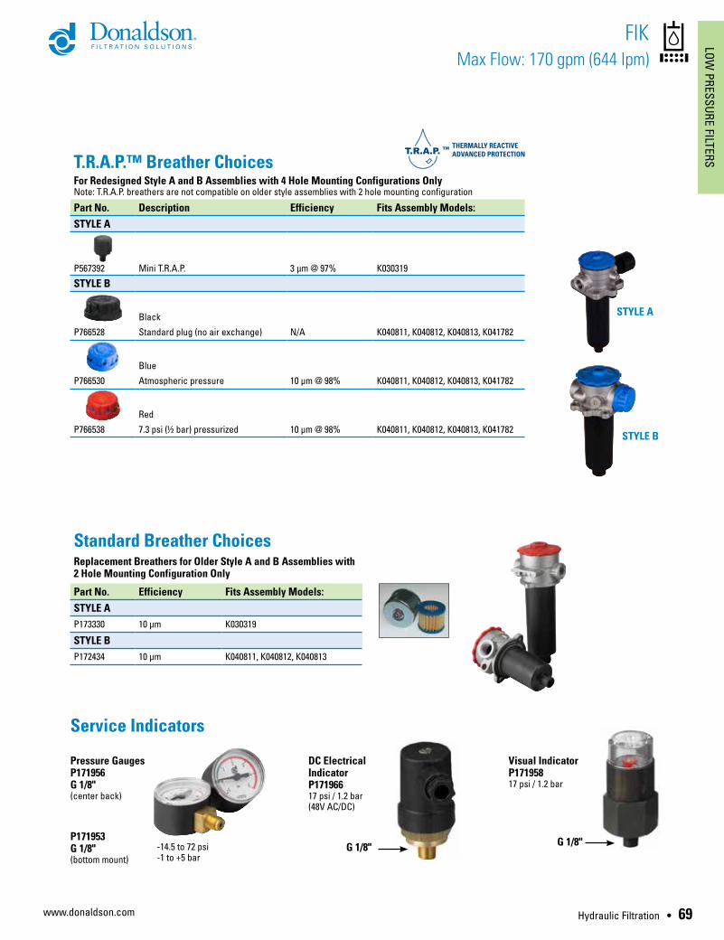
T.R.A.P.™ Breather ChoicesFor Redesigned Style A and B Assemblies with 4 Hole Mounting Configurations OnlyNote: T.R.A.P. breathers are not compatible on older style assemblies with 2 hole mounting configuration
Part No. Description Efficiency Fits Assembly Models:STYLE A
P567392 Mini T.R.A.P. 3 µm @ 97% K030319
STYLE B
Black
P766528 Standard plug (no air exchange) N/A K040811, K040812, K040813, K041782
Blue
P766530 Atmospheric pressure 10 µm @ 98% K040811, K040812, K040813, K041782
Red
P766538 7.3 psi (½ bar) pressurized 10 µm @ 98% K040811, K040812, K040813, K041782
FIK Max Flow: 170 gpm (644 lpm)
DC Electrical IndicatorP17196617 psi / 1.2 bar (48V AC/DC)
Visual IndicatorP17195817 psi / 1.2 bar
Pressure GaugesP171956G 1/8"(center back)
Service Indicators
P171953 G 1/8"(bottom mount)
G 1/8" G 1/8"-14.5 to 72 psi-1 to +5 bar
Standard Breather ChoicesReplacement Breathers for Older Style A and B Assemblies with 2 Hole Mounting Configuration Only
Part No. Efficiency Fits Assembly Models: STYLE AP173330 10 µm K030319
STYLE BP172434 10 µm K040811, K040812, K040813
STYLE A
STYLE B

70 • Hydraulic Filtration
LOW
PRE
SSUR
E FI
LTER
S
www.donaldson.com
FIK Components
FIK Max Flow: 170 gpm (644 lpm)
Filter Choices - Low Flow AssembliesMedia ß
x(c) = 2 ß
x(c) = 1000 Length Donaldson
Type Rating based on ISO 16889 in mm Part No.STYLE B K040811Synteq Synthetic 11 µm 3.23 82 P171525
23 µm 3.23 82 P171526
Cellulose 7 µm 3.23 82 P171527
27 µm 3.23 82 P171528
Wire Mesh 60 µm 3.23 82 P171529
90 µm 3.23 82 P171524
K040812Synteq Synthetic 6 µm 5.04 128 P569275
11 µm 5.04 128 P171531
23 µm 5.04 128 P171532
Cellulose 7 µm 5.04 128 P171533
27 µm 5.04 128 P171534
Wire Mesh 60 µm 5.04 128 P171535
90 µm 5.04 128 P171530
K040813Synteq Synthetic 6 µm 8.27 210 P569276
11 µm 8.27 210 P171846
23 µm 8.27 210 P171843
Cellulose 7 µm 8.27 210 P171840
27 µm 8.27 210 P171837
Wire Mesh 60 µm 8.27 210 P171834
K041782Synteq Synthetic 6 µm 8.27 210 P569276
11 µm 8.27 210 P171846
23 µm 8.27 210 P171843
Cellulose 7 µm 8.27 210 P171840
27 µm 8.27 210 P171837
Wire Mesh 60 µm 8.27 210 P171834
Filter Choices - Low Flow AssembliesMedia ß
x(c) = 2 ß
x(c) = 1000 Length Donaldson
Type Rating based on ISO 16889 in mm Part No.STYLE A K030319Synteq Synthetic 6 µm 6.38 162 P569273
11 µm 6.38 162 P171845
23 µm 6.38 162 P171842
Cellulose 7 µm 6.38 162 P171839
27 µm 6.38 162 P171836
Wire Mesh 60 µm 6.38 162 P171833
90 µm 6.38 162 P171830

Hydraulic Filtration • 71
LOW PRESSURE FILTERS
www.donaldson.com
High Flow AssembliesMedia ß
x(c) = 2 ß
x(c) = 1000 Length Donaldson
Type Rating based on ISO 16889 in mm Part No.STYLE C K031027Synteq Synthetic 6 µm 2.64 67 P569277
11 µm 2.64 67 P171501
23 µm 2.64 67 P171502
Cellulose 7 µm 2.64 67 P171503
27 µm 2.64 67 P171504
Wire Mesh 60 µm 2.64 67 P171505
90 µm 2.64 67 P171500
K041770Synteq Synthetic 11 µm 3.23 82 P171525
23 µm 3.23 82 P171526
Cellulose 7 µm 3.23 82 P171527
27 µm 3.23 82 P171528
Wire Mesh 60 µm 3.23 82 P171529
90 µm 3.23 82 P171524
K041771, K041772, K041773, K041774, K040799Synteq Synthetic 6 µm 5.04 128 P569275
11 µm 5.04 128 P171531
23 µm 5.04 128 P171532
Cellulose 7 µm 5.04 128 P171533
27 µm 5.04 128 P171534
Wire Mesh 60 µm 5.04 128 P171535
90 µm 5.04 128 P171530
K040798Synteq Synthetic 6 µm 8.22 209 P569276
11 µm 8.22 209 P171846
23 µm 8.22 209 P171843
Cellulose 7 µm 8.22 209 P171840
27 µm 8.22 209 P171837
Wire Mesh 60 µm 8.22 209 P171834
High Flow AssembliesMedia ß
x(c) = 2 ß
x(c) = 1000 Length Donaldson
Type Rating based on ISO 16889 in mm Part No.STYLE DK070248, K071001Synteq Synthetic 6 µm 7.49 203 P569279
11 µm 7.49 203 P171555
23 µm 7.49 203 P171556
Cellulose 7 µm 7.49 203 P171557
27 µm 7.49 203 P171558
Wire Mesh 60 µm 7.49 203 P171559
K070249, K071002Synteq Synthetic 6 µm 9.84 250 P569280
11 µm 9.84 250 P171573
23 µm 9.84 250 P171574
Cellulose 7 µm 9.84 250 P171575
27 µm 9.84 250 P171576
Wire Mesh 90 µm 9.84 250 P171572
K070250, K071003Synteq Synthetic 6 µm 15.75 400 P176749
11 µm 15.75 400 P171579
23 µm 15.75 400 P171580
Cellulose 7 µm 15.75 400 P171581
27 µm 15.75 400 P171582
Wire Mesh 60 µm 15.75 400 P171583
90 µm 15.75 400 P171578
STYLE EK051204, K052053Synteq Synthetic 6 µm 7.49 203 P569278
11 µm 7.49 203 P171537
23 µm 7.49 203 P171538
Cellulose 7 µm 7.49 203 P171539
27 µm 7.49 203 P171540
Wire Mesh 60 µm 7.49 203 P171541
90 µm 7.49 203 P171536
FIK Max Flow: 170 gpm (644 lpm)

72 • Hydraulic Filtration
LOW
PRE
SSUR
E FI
LTER
S
www.donaldson.com
Performance Data
FIK Max Flow: 170 gpm (644 lpm)
STYLE A
STYLE B
STYLE C
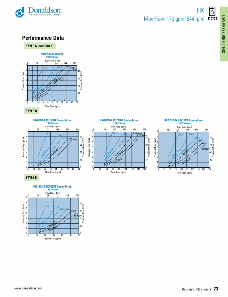
NOTE: Please note that the line styles used represent different media types
Synteq SyntheticCelluloseWire Mesh
Hydraulic Filtration • 73
LOW PRESSURE FILTERS
www.donaldson.com
Performance Data
FIK Max Flow: 170 gpm (644 lpm)
STYLE C, continued
STYLE D
STYLE E