Mattishall Forge, Kensington Strategy Development Drainage ...
25
Proposed Housing Development – Kensington Forge, Mattishall Drainage Strategy
Transcript of Mattishall Forge, Kensington Strategy Development Drainage ...

Proposed Housing Development – Kensington Forge, M
attishall
Drainage Strategy

PROPOSED HOUSING DEVELOPMENT
KENSINGTON FORGE, MATTISHALL
Drainage Strategy
Client: Mr & Mrs Plummer
Engineer: Create Consulting Engineers Limited
15 Princes Street
Norwich
Norfolk
NR3 1AF
Tel: 0845 450 7908
Email: [email protected]
Web: www.createconsultingengineers.co.uk
Report By: Philip Porter, IEng, MCIHT, AMICE
Checked By: Gordon Hodgkinson
Reference: PP/CS/P12‐381/01
Date: April 2014
Proposed Housing Development – Kensington Forge, M
attishall
Drainage Strategy

Proposed Housing Development – Kensington Forge, Mattishall Drainage Strategy
Ref: PP/CS/P12‐381/01 Page 1
PROPOSED HOUSING DEVELOPMENT
KENSINGTON FORGE, MATTISHALL
Drainage Strategy
Contents
1.0 Introduction
2.0 The Site History
3.0 The Site Proposals
4.0 Existing Surface Water Drainage
5.0 Proposed Surface Water Drainage Strategy
6.0 Proposed Foul Water Drainage Strategy
7.0 Guidance and Policies
8.0 Discussion and Recommendation
9.0 Disclaimer
Appendices
A. Proposed Masterplan for Site
B. Drainage Strategy Drawing
C. Windes (Microdrainage) Calculations
D. Anglian Water Asset Plan
Registration of Amendments
Revision Amendment Details Revision
Prepared By
Revision
Approved
By

Proposed Housing Development – Kensington Forge, Mattishall Drainage Strategy
Ref: PP/CS/P12‐381/01 Page 2
1.0 INTRODUCTION
1.1 Mr and Mrs Plummer of Kensington Forge, Dereham Road, Mattishall, have applied to
Breckland District Council for a change of use on an area of land that they own from mixed
residential and light industrial to residential. This report describes the strategy for draining
the land.
1.2 The Strategy Statement demonstrates that:
a. It is possible to drain the site to outfall in the ditch along the sides of the property.
b. Connections to the foul water sewer are available.
1.3 The surface water management proposals demonstrate that there is no increased risk of
flooding within the site or onto adjacent areas of land.
1.4 This Statement is prepared in support of and as an explanation to the calculations and
drawings included as appendices to this report.
1.5 The development is contained within Zone 1 which is defined by the Environment Agency as
‘land having less than 1 in 1,000 annual probability of river or sea flooding’. The
Environment Agency identifies that all uses of land are appropriate in this zone. It is also
identified that flood risk assessments or drainage strategies are only appropriate within
Zone 1 for sites of 1 Hectare or above. The site reviewed herein is 0.947 Hectares in area
but a drainage strategy has been called for by the local planning authority.

Proposed Housing Development – Kensington Forge, Mattishall Drainage Strategy
Ref: PP/CS/P12‐381/01 Page 3
2.0 THE SITE HISTORY
2.1 The Site is located to the south of Dereham Road on the western side of the village of
Mattishall, as shown below in Figure 2.1.
Contains Ordnance Survey data © Crown copyright and database rights 2013.
Figure 2.1: Site Location
2.2 The site has had a number of uses over the years, commencing as agricultural land with
various parts of the site being designated for residential, light industrial and wood recycling
over the years.
2.3 Currently, the front part of the site adjacent to Dereham Road contains a workshop building
used as a welding shop and office and an incomplete storage building. Towards the rear of
the site and on the eastern boundary, a mobile home and garden are sited and the south
west of the site is currently an area of grassland and outside storage that enjoys planning
approval for use as a wood recycling facility.
Site Location

Proposed Housing Development – Kensington Forge, Mattishall Drainage Strategy
Ref: PP/CS/P12‐381/01 Page 4
3.0 THE SITE PROPOSALS
3.1 As stated previously, the site currently has the benefit of a mixture of residential and light
industrial planning approval.
3.2 The proposal, subject to planning approval, is to clear the site of the existing uses and erect
eleven dwellings constructed to Passivhaus standards. Of these eleven dwellings, four
would be offered as affordable housing.
3.3 The site would be accessed via a new junction with the Dereham Road located along the
northern boundary of the site. This access road would be constructed to adoptable highway
standards (ie have an impermeable paved area) with the driveways servicing the properties
along its length, being constructed of permeable paving materials.
3.4 Drawing 3098.06.D enclosed in Appendix A shows the proposed layout of the site.

Proposed Housing Development – Kensington Forge, Mattishall Drainage Strategy
Ref: PP/CS/P12‐381/01 Page 5
4.0 EXISTING SURFACE WATER DRAINAGE
4.1 The site is currently drained by a combination of very small soakaways and overland flow to
outfall in the existing ditch.
4.2 The existing forge and mobile home are served by soakaways. The ground conditions on the
site consist mainly of Boulder Clay with some Alluvial Fan along the eastern boundary of the
site. Neither of these materials is particularly free draining and therefore the soakaways
used are relatively large in relation to the flow of water they cater for.
4.3 The workshop and mobile home are serviced by soakaways with the remainder of the site
draining to the ditch by means of overland flow. In the area of the workshop and
incomplete storage building, there is a small yard area paved with compacted stone and
gravel and a small area of grass land. To the rear of the site lies the residential area which is
mainly surrounded by grassland. Whilst the residential units are served by soakaways, the
remainder of the area relies upon overland flow to the ditches along the western boundary
of the property.
4.4 The open storage land to the south of the property is served wholly by overland flow. It
consists of an overgrown grassed area with a few spoil heaps from previous building works
spread around. The area is currently used for the external storage of wood and vehicles.
4.5 The run off from this area flows overland to the ditch along the western edge of the
property.
4.6 The ditch along the western edge of the property is approximately 1.2m deep throughout its
length. The top and lip of the ditch sides are well covered with vegetation and the bottom
has a layer of rotting leaves but is generally clear.
4.7 The ditch falls from the south west corner of the site along the western boundary towards
Dereham Road. As it approaches the road, it flows to the west to become a ditch parallel
with the south channel of Dereham Road. The depth of the ditch along this section is slightly
less than that along the boundary of the property. Despite a period of heavy rain prior to
the site inspection, there was no sign of the ditch overtopping the banks and flowing onto
either the road or the fields.

Proposed Housing Development – Kensington Forge, Mattishall Drainage Strategy
Ref: PP/CS/P12‐381/01 Page 6
5.0 PROPOSED SURFACE WATER DRAINAGE STRATEGY
5.1 In formulating this drainage strategy, due recognition has been taken of the ground
conditions indicated by the BGS mapping. The ground strata of either the Alluvial Fan or the
Boulder Clay would indicate that soakage rates would be very poor. For this reason, a
prudent approach has been taken to assume that stormwater from roofs and the access
road can be put to a soakaway but should be taken to a positive outfall.
5.2 The approach taken in the design of the surface water drainage network for the site has
been to provide attenuation near to the point of collection before discharging into the piped
network that runs under the access road. Pipes in the network under the access road have
been appropriately sized to accommodate flows from the attenuation to the discharge point
at the ditch to the northeast corner of the Site.
5.3 In undertaking the preliminary drainage design, rainfall data has been identified from the
latest available EA data. Impermeable areas have been calculated from the latest architect’s
masterplan drawing number 3098.06.D and the run off input into Microdrainage to calculate
the flows in each run of the pipe network. Flow restrictions to determine the level of
attenuation have been built into the model.
5.4 To inform the drainage strategy, the DoH 124 Calculation of Greenfield Runoff Rate has been
used to establish a rate of runoff for the 1 in 100 year storm (+30% climate change) to the
ditch outfall. Based on a proposed impermeable area of development of 0.379 ha, the rate
for the 1 in 100 year storm (+30% climate change) is 4.2 l/s. Owing to the practicalities of
controlling waterflow rates, a rate of 5 l/s has been used.
5.5 This strategy proposes the use of a vortex control device (HydraBrake or Similar) to control
the flow of stormwater to no more than 5 l/s in the critical 1 in 100 year storm (+30%
climate change). Water is proposed to be attenuated within below ground cellular storage
creates (Wavin or similar).
5.6 Flows from the roofs of plots 1 to 5 will be stored in cellular storage structure located to the
rear of the plots with flows to the drainage network controlled by an orifice plate.
5.7 Stormwater from the impermeable access road and the roofs of plots 6‐11 will be directed
to the drainage network laid under the access road with the ultimate flow to ditch controlled
by a vortex control device. Attenuation, again in the form of below ground cellular storage
structure is proposed to the rear of plots 8‐11.
5.8 The indicative drainage network is shown on the attached drawing in Appendix B.
5.9 The detailed design of the drainage system will be undertaken in accordance with Sewers for
Adoption (6th Edition). Although it is not known at this time whether or not the sewer would

Proposed Housing Development – Kensington Forge, Mattishall Drainage Strategy
Ref: PP/CS/P12‐381/01 Page 7
be offered for adoption, it has been decided to design and construct to these standards to
retain the option of offering it for adoption at a later date.
Alternative Strategies
5.10 The alternative strategies considered during the development of this preferred design are
discussed below:
Soakaways
5.11 As stated earlier, BGS data has been reviewed and it is noted that the sub‐soils indicated are
unlikely to offer any real infiltration. On this basis, the decision was taken to adopt the most
cautious approach possible direct roof and access road water to a positive outfall. In this
manner, should the developer wish to consider soakways at a later date, these could be
added into the system (subject to testing and suitable infiltration rates).
Grass Swales or Basins
5.12 As can be seen from the architect’s drawing, neither the site nor the masterplan layout
would be suitable for swales or basins.
Permeable Paving
5.13 Permeable paving has been considered and driveways to all plots are proposed to be gravel.
Storage beneath the access road pavement could be provided by granular fills. However,
permeable paving is not considered to be an adoptable form of road construction by the
local highway authority. This option has therefore been discounted on adoption grounds.
Detention Ponds and Swales
5.14 The site area is restricted and there is little space available for such features and the health
and safety implications of deep water near to residential property would preclude this
option.
Below Ground Attenuation
5.15 The primary advantage of this alternative is the fact that the storage areas can be covered
by other uses, such as open space or gardens.
5.16 The proposed storage structures have been sited in garden areas and below a parking court.
The drawing shows the areas proposed for the construction of the storage features but the
size and number (ie smaller spaced out structures instead of a large central structure) will be
determined at the detailed design stage.
Proposed Housing Development – Kensington Forge, Mattishall Drainage Strategy
Ref: PP/CS/P12‐381/01 Page 8
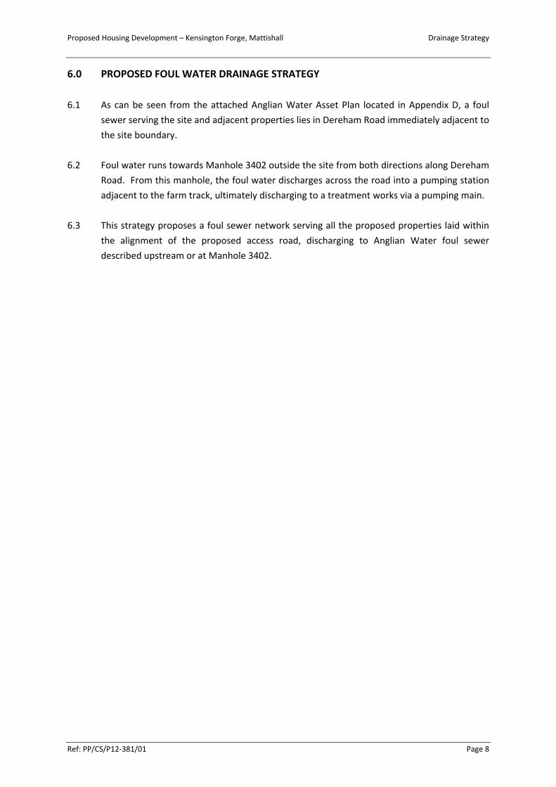
6.0 PROPOSED FOUL WATER DRAINAGE STRATEGY
6.1 As can be seen from the attached Anglian Water Asset Plan located in Appendix D, a foul
sewer serving the site and adjacent properties lies in Dereham Road immediately adjacent to
the site boundary.
6.2 Foul water runs towards Manhole 3402 outside the site from both directions along Dereham
Road. From this manhole, the foul water discharges across the road into a pumping station
adjacent to the farm track, ultimately discharging to a treatment works via a pumping main.
6.3 This strategy proposes a foul sewer network serving all the proposed properties laid within
the alignment of the proposed access road, discharging to Anglian Water foul sewer
described upstream or at Manhole 3402.

Proposed Housing Development – Kensington Forge, Mattishall Drainage Strategy
Ref: PP/CS/P12‐381/01 Page 9
7.0 GUIDANCE AND POLICIES
7.1 Sewers for Adoption 6th Edition provides guidance to developers for the design and
construction of both Surface and Foul Water Sewers to be offered for Adoption. This
guidance is provided in consultation with the Water Undertakers.
7.2 The guidance in Sewers for Adoption states:
“An appropriate flow simulation method based on the Wallingford Procedure should be used
for hydraulic design unless otherwise greed with the undertaker, eg in the case of small
developments.”
Windes (Microdrainage) has been used for all the calculations herein.
7.3 The Building Regulations 2000, Part H ‘Drainage and Waste Disposal’, gives guidance on the
design of private sewers. Part H3 deals specifically with Rainwater Drainage.
7.4 The designs and calculations included herein conform to all of this guidance.

Proposed Housing Development – Kensington Forge, Mattishall Drainage Strategy
Ref: PP/CS/P12‐381/01 Page 10
8.0 DISCUSSION AND RECOMMENDATIONS
8.1 The Environment Agency mapping has been consulted and has shown that the site lies
within Zone 1 and is defined as having a ‘very low’ risk of flooding from rivers or surface
water run off. Very low is defined by the Environment Agency as having a chance of flooding
of less than 1 in 1,000 years.
8.2 The Environment Agency guidance identifies that sites having a site area of less than
1 Hectare and included within Zone 1 on the flood maps do not require a Flood Risk
Assessment. However, it also advises that sites greater than 1 Hectare, whilst still not
requiring a full Flood Risk Assessment, should have a defined Drainage Strategy to identify
that the site can be adequately drained without creating a risk of increased flooding to
properties elsewhere. The site examined herein is approximately 0.947 Hectares in area.
However, in the interests of a robust design, the Strategy presented herein is provided in
support of the application.
8.3 A review of British Geological Society (BGS) mapping has indicated that the site is founded
upon impermeable sub‐soils that are likely to have very low soakage rates. The ground
conditions have been confirmed by inspection on site. In the interests of a prudent analysis,
therefore, the use of soakaways has been discounted and the drainage designed to outfall to
a local watercourse whilst keeping the outfall rates down to the equivalent ‘Greenfield’ run
off rates of 5 l/s.
8.4 The historical records for the area have been reviewed and it is noted that there are no
records of flooding to adjacent properties or highways within the area.
8.5 The SUDS Strategy therefore utilises a combination of retention features and flow controls
via a piped system to a positive outfall in a local watercourse. The provision of this system
enables the outflow to be constrained to the equivalent outfall of the existing undeveloped
site area. It therefore complies with the basic requirement of SUDS systems to reduce the
impact of the development on flood risk to surrounding properties.
8.6 The cellular structures intended to be used as attenuation features have been sited within
the rear gardens and amenity areas of the property. Whilst the initial design indicates the
use of a central feature serving a number of properties, further detailed design may indicate
that smaller more separated facilities would be better provided assuming that the capacity
of the single features is equalled or bettered.
8.7 Storage within the suitable sized pipe network may also be used to control outflows at the
detailed design stage.
8.8 Foul drainage would be directed to the existing manhole and pumping station immediately
adjacent to the existing site entrance.

Proposed Housing Development – Kensington Forge, Mattishall Drainage Strategy
Ref: PP/CS/P12‐381/01 Page 11
8.9 In keeping with good hydraulic design practice, all drainage runs and structures will be
designed to ensure that self‐cleaning velocities are achieved in order to reduce the risk of
blockages.

Proposed Housing Development – Kensington Forge, Mattishall Drainage Strategy
Ref: PP/CS/P12‐381/01 Page 12
9.0 DISCLAIMER
9.1 Create Consulting disclaims any responsibility to the Client and others in respect of any
matters outside the scope of this report.
9.2 The copyright of this report is vested in Create Consulting Engineers Ltd and Paul Plummer.
The Client, or his appointed representatives, may copy the report for purposes in connection
with the development described herein. It shall not be copied by any other party or used for
any other purposes without the written consent of Create Consulting Engineers Ltd or Paul
Plummer.
9.3 Create Consulting Engineers Ltd accepts no responsibility whatsoever to other parties to
whom this report, or any part thereof, is made known. Any such other parties rely upon the
report at their own risk.

APPENDICES

APPENDIX A

This line measures 200mm in length when printed correctly
Project:
Client:
Title:
Date:Revision Details:
Parsons + Whittley Ltd Architects
1 London Street, Swaffham
Norfolk, PE37 7DD
Phone: 01760 722000
email: [email protected]
web: www.parsonswhittley.co.uk
3098.06 D A
2draw
ing number: rev: size:
Proposed PASSIVHAUS DevelopmentKensington ForgeDereham RoadMattishall
Mr & Mrs P Plummer
Site Plan
07-04-14
1:500 Site Layout
n
1 2 3 45
6
7
11Typical dwellings 1-7 shown @ 2420sq ft/ 225 sqm, excluding garages and car-ports,
plots 8, 10 & 11 shown as 4-person 2-bed affordable homes @ 818 sq ft/ 76sqm
plot 9 shown as 2-person 1-bed affordable home @ 603 sq ft/ 56sqm
8 9 10
plots 7-11 and access road revised
Dereham Road
existing access to be stopped up and landscaped to NCC requirements
existing forge to be demolished
Dereham Road
1:2500 Site Location
n
tree to be removed
existing footpath to village
link development to existing footpath
existing Konect 4 bus stop at entrance to development
existing Leylandii hedge along western boundary to be removed
slab level xx.xx
slab level xx.xx
slab level xx.xx
slab level xx.xx
double garage 2
double garage 3
double garage 1
slab level xx.xx
triple garage 4 triple
garage 5slab level xx.xx
slab level xx.xx
slab level xx.xx
double garage 6
slab level xx.xx
slab level xx.xx
double garage 7
slab level xx.xx
Plots 8-11 slab level xx.xx
refer to arboricultural report for details of root protection areas to existing trees
native-species hedge and tree planting to boundaries to form part of a lanscaping scheme to be submitted to, and approved by, local authority
size 3 turning
access road to NCC Norfolk Residential Design Guide adoptable standard, type 6
private drives shown thus
existing Konect 4 bus stop at entrance to development
refer to engineer's drawing xxx for details of new access and visibility splay
slab level xx.xx
existing buildings to be removed shown dotted
PRELIMINARY

APPENDIX B

PLOT 1
FFL: 45.000
PLOT 2
FFL: 45.000
PLOT 3
FFL: 45.000
PLOT 4
FFL: 45.000
PLOT 5
FFL: 45.000
PLOT 6
FFL: 45.500
PLOT 7
FFL: 44.000
PLOT 8, 9, 10
FFL: 44.000
1.002
1
.
0
0
3
1
.0
0
4
1
.0
0
5
1
.0
0
6
1
.
0
0
7
1.001
ORI
GIN
AL
SHEE
T SI
ZE -
A1
Land
scap
eD
O N
OT
SCA
LE
DRAWING No REVISIONCLIENT
JOB No
SCALE(S)
DRAWING STATUSDATE
DESIGNED DRAWN
CHECKED APPROVED
PROJECT
DRAWING TITLE
AMENDMENT DETAILSREV DATE APPROVEDDRAWN
381
02/001 -MR. AND MRS. PLUMMER
KENSINGTON FORGE
PROPOSED DRAINAGE STRATEGY
22.04.14 INFORMATION
1:500GH TH
GH GH
Create Consulting Engineers accept no responsibility for any unauthorised amendments to this drawing. Only figured dimensions are to be worked to. COPYRIGHT © RESERVED
CELLULAR STORM WATER STORAGE
SIZED TO ACCOMMODATE THE 1 IN 100
YEAR (+30% CLIMATE CHANGE) STORM
EVENT WITH A CONTROLLED RATE OF
NO MORE THAN 5+ L/S THE EQUIVALENT
GREEN FIELD RATE INTO THE DITCH
HYDROBRAKE (OR SIMILAR)
FLOW CONTROLLED TO 5 L/S
CELLULAR STORM WATER STORAGE FLOW
CONTROLLED TO 5L/S BY ORIFICE PLATE
DEPTH OF DITCH CIRCA 1.2m
PROPOSED STORM WATER SEWER
PROPOSED FOUL WATER SEWER
PROPOSED STORM WATER MANHOLE
PROPOSED FOUL WATER MANHOLE
CELLULAR STORM WATER STORAGE
KEY:
NOTES:
1. THIS DRAWING IS BASED ON TOPOGRAPHIC SURVEY PROVIDED BY EAST ANGLIANSURVEYS LTD DRAWING NO. "8360-1" DATED 28.06.2013 AND MASTER PLANPROVIDED BY PARSONS + WHITTLEY LTD ARCHITECTS DRAWING "3098 current d - engissue" RECEIVED 01.04.2014.
FOUL SEWER TO
DISCHARGE TO
ADOPTED SEWER
LOCATED IN
DEREHAM ROAD
MH 3402 (IL 39.639)
TOP BANK: 43.37
ASSUMED IL: 42.17
STORMWATER
DISCHARGE TO
EXISTING DITCH

APPENDIX C

Create Consulting Page 1
15 Princes Street Kensington Forge
Norwich Storm Strategy Calcs
NR3 1AF
Date 24/04/2014 16:40 Designed by GH
File net 1 revised layout.mdx Checked by
Causeway Network 2013.1.1
STORM SEWER DESIGN by the Modified Rational Method
Design Criteria for Storm
©1982-2013 Micro Drainage Ltd
Pipe Sizes STANDARD Manhole Sizes STANDARD
FSR Rainfall Model - England and WalesReturn Period (years) 100
M5-60 (mm) 20.000Ratio R 0.401
Maximum Rainfall (mm/hr) 50Maximum Time of Concentration (mins) 30
Foul Sewage (l/s/ha) 0.000Volumetric Runoff Coeff. 0.750
Add Flow / Climate Change (%) 30Minimum Backdrop Height (m) 0.200Maximum Backdrop Height (m) 1.500
Min Design Depth for Optimisation (m) 1.200Min Vel for Auto Design only (m/s) 1.00
Min Slope for Optimisation (1:X) 500
Designed with Level Soffits
Network Design Table for Storm
PNPNPNPN LengthLengthLengthLength(m)(m)(m)(m)
FallFallFallFall(m)(m)(m)(m)
SlopeSlopeSlopeSlope(1:X)(1:X)(1:X)(1:X)
I.AreaI.AreaI.AreaI.Area(ha)(ha)(ha)(ha)
T.E.T.E.T.E.T.E.(mins)(mins)(mins)(mins)
BaseBaseBaseBaseFlow (l/s)Flow (l/s)Flow (l/s)Flow (l/s)
kkkk(mm)(mm)(mm)(mm)
HYDHYDHYDHYDSECTSECTSECTSECT
DIADIADIADIA(mm)(mm)(mm)(mm)
1.000 5.000 0.030 168.4 0.114 5.00 0.0 0.600 o 2251.001 25.000 0.148 168.9 0.000 0.00 0.0 0.600 o 3001.002 40.000 0.192 208.0 0.028 0.00 0.0 0.600 o 3001.003 10.000 0.130 76.9 0.000 0.00 0.0 0.600 o 3001.004 40.000 0.250 160.0 0.070 0.00 0.0 0.600 o 3001.005 30.000 0.297 101.2 0.055 0.00 0.0 0.600 o 300
2.000 10.000 0.067 149.3 0.017 5.00 0.0 0.600 o 300
1.006 15.000 0.075 200.0 0.000 0.00 0.0 0.600 o 3001.007 43.000 0.215 200.0 0.000 0.00 0.0 0.600 o 300
Network Results Table
PNPNPNPN RainRainRainRain(mm/hr)(mm/hr)(mm/hr)(mm/hr)
T.C.T.C.T.C.T.C.(mins)(mins)(mins)(mins)
US/ILUS/ILUS/ILUS/IL(m)(m)(m)(m)
Σ I.AreaΣ I.AreaΣ I.AreaΣ I.Area(ha)(ha)(ha)(ha)
Σ BaseΣ BaseΣ BaseΣ BaseFlow (l/s)Flow (l/s)Flow (l/s)Flow (l/s)
FoulFoulFoulFoul(l/s)(l/s)(l/s)(l/s)
Add FlowAdd FlowAdd FlowAdd Flow(l/s)(l/s)(l/s)(l/s)
VelVelVelVel(m/s)(m/s)(m/s)(m/s)
CapCapCapCap(l/s)(l/s)(l/s)(l/s)
FlowFlowFlowFlow(l/s)(l/s)(l/s)(l/s)
1.000 50.00 5.08 43.575 0.114 0.0 0.0 4.6 1.00 39.9 20.11.001 50.00 5.43 43.470 0.114 0.0 0.0 4.6 1.21 85.3 20.11.002 50.00 6.04 43.322 0.142 0.0 0.0 5.8 1.09 76.8 25.01.003 50.00 6.13 43.130 0.142 0.0 0.0 5.8 1.79 126.8 25.01.004 50.00 6.67 43.000 0.212 0.0 0.0 8.6 1.24 87.7 37.31.005 50.00 6.99 42.750 0.267 0.0 0.0 10.8 1.56 110.5 47.0
2.000 50.00 5.13 42.520 0.017 0.0 0.0 0.7 1.28 90.8 3.0
1.006 50.00 7.22 42.453 0.284 0.0 0.0 11.5 1.11 78.3 50.01.007 50.00 7.86 42.378 0.284 0.0 0.0 11.5 1.11 78.3 50.0
Free Flowing Outfall Details for Storm
OutfallOutfallOutfallOutfallPipe NumberPipe NumberPipe NumberPipe Number
OutfallOutfallOutfallOutfallNameNameNameName
C. LevelC. LevelC. LevelC. Level(m)(m)(m)(m)
I. LevelI. LevelI. LevelI. Level(m)(m)(m)(m)
MinMinMinMinI. LevelI. LevelI. LevelI. Level
(m)(m)(m)(m)
D,LD,LD,LD,L(mm)(mm)(mm)(mm)
WWWW(mm)(mm)(mm)(mm)
1.007 43.370 42.163 42.170 0 0

Create Consulting Page 2
15 Princes Street Kensington Forge
Norwich Storm Strategy Calcs
NR3 1AF
Date 24/04/2014 16:40 Designed by GH
File net 1 revised layout.mdx Checked by
Causeway Network 2013.1.1
Simulation Criteria for Storm
©1982-2013 Micro Drainage Ltd
Volumetric Runoff Coeff 0.750 Additional Flow - % of Total Flow 0.000Areal Reduction Factor 1.000 MADD Factor * 10m³/ha Storage 2.000
Hot Start (mins) 0 Inlet Coeffiecient 0.800Hot Start Level (mm) 0 Flow per Person per Day (l/per/day) 0.000
Manhole Headloss Coeff (Global) 0.500 Run Time (mins) 60Foul Sewage per hectare (l/s) 0.000 Output Interval (mins) 1
Number of Input Hydrographs 0 Number of Storage Structures 2Number of Online Controls 2 Number of Time/Area Diagrams 0
Number of Offline Controls 0 Number of Real Time Controls 0
Synthetic Rainfall Details
Rainfall Model FSR Profile Type SummerReturn Period (years) 100 Cv (Summer) 0.750
Region England and Wales Cv (Winter) 0.840M5-60 (mm) 20.000 Storm Duration (mins) 30
Ratio R 0.401

APPENDIX D

Pumping Station
Manhole
Inlet
Outfall
Sewage Treatment Works
Foul Sewer
Final Effluent
Decommissioned Sewer
(Colour denotes effluent type)
(Colour denotes effluent type)
Surface SewerCombined Sewer
(Colour denotes effluent type)
(Colour denotes effluent type)
(Colour denotes effluent type)
This plan is provided by Anglian Water pursuant its obligations under the Water Industry Act 1991 sections 198 or 199. It must be used in conjunction with any search results attached. The information on this plan is based on data currently recorded but position must be regarded as approximate. Service pipes, private sewers and drains are generally not shown. Users of this map are strongly advised to commission their own survey of the area shown on the plan before carrying out any works. The actual position of all apparatus MUST be established by trial holes. No liability whatsoever, including liability for negligence, is accepted by Anglian Water for any error or inaccuracy or omission, including the failure to accurately record, or record at all, the location of any water main, discharge pipe, sewer or disposal main or any item of apparatus. This information is valid for the date printed. The plan is produced by Anglian Water Services Limited from Ordnance Survey © Crown Copyright, 100018507. This map is to be used for the purposes of viewing the location of Anglian Water plant only. Any other uses of the map data or further copies is not permitted. This notice is not intended to exclude or restrict liability for death or personal injury resulting from negligence.
Date: 10/10/13 Scale: 1:1250 Data updated: 01/08/13Map Centre: 603348,311399(c) Crown Copyright and database rights 2011 Ordnance Survey 100018507 Wastewater Plan A3Our Ref: 76276 - 1
3098 Plummer
Private Sewer
Rising Main
(Colour denotes effluent type)

Manhole Reference Liquid Type Cover Level Invert Level Depth to Invert
1402 F 42.416 40.666 1.75
1501 F 42.835 41.255 1.58
3401 F 42.459 40.069 2.39
3402 F 42.689 39.639 3.05
3403 F 42.727 39.987 2.74
3404 F - - -
4301 F 42.647 40.337 2.31
4302 F 42.791 40.581 2.21
4303 F 42.824 41.044 1.78
Manhole Reference Liquid Type Cover Level Invert Level Depth to Invert
Manhole Reference Liquid Type Cover Level Invert Level Depth to Invert
Our Ref: 76276 - 1