Matrix Switcher/ Controller Installation/ Operation Manual ... · PDF fileMatrix Switcher/...
86
CM6800-48X8 Matrix Switcher/ Controller Installation/ Operation Manual C1515M-A (11/01) Pelco • 3500 Pelco Way˚• Clovis, CA 93612-5699 USA • www.pelco.com In North America and Canada: Tel (800) 289-9100 or FAX (800) 289-9150 International Customers: Tel +1 (559) 292-1981 or FAX +1 (559) 348-1120 ®
Transcript of Matrix Switcher/ Controller Installation/ Operation Manual ... · PDF fileMatrix Switcher/...

CM6800-48X8Matrix Switcher/
Controller
Installation/Operation Manual
C1515M-A (11/01)
Pelco • 3500 Pelco Way • Clovis, CA 93612-5699 USA • www.pelco.com
In North America and Canada: Tel (800) 289-9100 or FAX (800) 289-9150
International Customers: Tel +1 (559) 292-1981 or FAX +1 (559) 348-1120
®

2 Pelco Manual C1515M-A (11/01)
CONTENTS
Section Page
IMPORTANT SAFEGUARDS AND WARNINGS ................................................................ 6
DESCRIPTION ...................................................................................................................7MODELS ...................................................................................................................10
ASSOCIATED EQUIPMENT ............................................................................. 10
INSTALLATION ................................................................................................................. 11MOUNTING ............................................................................................................... 11VIDEO SOURCES ....................................................................................................12CONTROL LINES .....................................................................................................14MONITORS ...............................................................................................................15ALARMS ...................................................................................................................16CONNECTING DEVICES THROUGH THE COMMUNICATION PORTS ................. 17
KBD100, KBD200, AND KBD300 SERIES KEYBOARDS ................................ 20M DEVICES ...................................................................................................... 23CONNECTING A PC ......................................................................................... 29CONNECTING GENEX MULTIPLEXERS ........................................................ 30
LOCAL AUXILIARIES ............................................................................................... 31
SYSTEM START-UP .........................................................................................................33POWER-UP THE SYSTEM....................................................................................... 33INITIALIZE KEYBOARDS ......................................................................................... 33CONFIGURE THE SYSTEM ..................................................................................... 33
TIME AND DATE ............................................................................................... 33CAMERA TITLES .............................................................................................. 34VIDEO SOURCES ............................................................................................ 34ALARMS ........................................................................................................... 34COMMUNICATION PORTS .............................................................................. 34KBD960/KBR960 KEYBOARD ......................................................................... 34GENEX MULTIPLEXER .................................................................................... 35MONITOR COLOR ADJUSTMENT: ..................................................................35PROGRAM PRESETS ...................................................................................... 35ADDITIONAL PROGRAMMING ........................................................................ 35
PROGRAMMING THE CM6800 ........................................................................................36CUSTOMIZING THE CM6800 .................................................................................. 36
ACCESS PROGRAMMING MODE FROM THE CM6800 ................................ 37NAVIGATE AND SELECT OPTIONS/FIELD ENTRIES INPROGRAMMING MODE .................................................................................. 38ABOUT CM6800 ............................................................................................... 40ACCESS (SYSTEM PARTITIONING) ............................................................... 40ALARM CONTACTS ......................................................................................... 42AUXILIARY OUTPUTS ..................................................................................... 49CAMERA ........................................................................................................... 50EVENT TIMERS ................................................................................................51LOGICAL CAMERA NUMBERS ....................................................................... 53MACROS .......................................................................................................... 54MACRO STATUS VIEW SCREEN .................................................................... 55MONITOR DISPLAY ......................................................................................... 56PASSWORD .....................................................................................................58PORTS (SERIAL/COM PORTS) ....................................................................... 59PRIORITY CONTROL....................................................................................... 60SEQUENCES ...................................................................................................61TIME AND DATE ............................................................................................... 62PATTERNS, PRESETS, AND ZONES.............................................................. 62

Pelco Manual C1515M-A (11/01) 3
OPERATION ..................................................................................................................... 63OVERVIEW ...............................................................................................................63OPERATING THE CM6800....................................................................................... 63
SWITCH MONITORS........................................................................................ 63SELECT CAMERAS ......................................................................................... 64CONTROL RECEIVERS ................................................................................... 64OPERATE SEQUENCES.................................................................................. 65RUN A MACRO ................................................................................................. 66ACKNOWLEDGE AN ALARM ........................................................................... 67CALL A PRESET ............................................................................................... 67CREATE AND RUN A PATTERN ...................................................................... 68OPERATE AUXILIARIES/RELAYS ................................................................... 68CONTROL GENEX MULTIPLEXER AND GENEX MULTIPLEXER DISPLAYS ... 70OPERATE SCANNING FUNCTIONS ............................................................... 70DETECT VIDEO LOSS ..................................................................................... 70DEFINE ZONES ............................................................................................... 70
APPENDIX ........................................................................................................................71CM6800 DIP SWITCHES .......................................................................................... 71MACRO COMMANDS .............................................................................................. 72ASCII OPERATING COMMANDS ............................................................................ 74TROUBLESHOOTING .............................................................................................. 77
GAINING INITIAL CONTROL ........................................................................... 77SOFTWARE RESET ......................................................................................... 77SOLUTIONS TO COMMON PROBLEMS ......................................................... 78
KBD960/KBR960 ICON/BUTTON LEGEND ............................................................. 79
GLOSSARY.......................................................................................................................80
SPECIFICATIONS............................................................................................................. 84
REGULATORY NOTICES ................................................................................................. 86
WARRANTY AND RETURN INFORMATION.................................................................... 86

4 Pelco Manual C1515M-A (11/01)
LIST OF ILLUSTRATIONS
Figure Page
1 CM6800 Application ........................................................................................... 72 Installing Rack Ears .......................................................................................... 113 Mounting the CM6800 Matrix Switcher/Controller ............................................ 114 CM6800 Video Inputs ........................................................................................125 Connecting Terminated Video Sources ............................................................. 136 Connecting Looping Video Sources ..................................................................137 PTZ Control Connections .................................................................................. 148 Connecting Monitors ......................................................................................... 159 Connecting Alarms ............................................................................................ 1610 Communication Port Connections and RJ-45 Connector Pin-Outs .................. 1711 CM6800 Communication Port Connections and Options ................................. 1912 Data Cable Plugged into Local Keyboard ......................................................... 2013 Data Cables Plugged into COM 5 and 6 ........................................................... 2014 Remote Keyboards ........................................................................................... 2215 RJ-45 Cable Types ............................................................................................ 2316 Connecting a KBD960/KBR960 to the CM6800 ............................................... 2417 Connecting a Single ALM2064 Alarm Interface Unit ......................................... 2518 Connecting a Single REL2064 Relay Interface Unit ......................................... 2619 Connecting Multiple M Devices – Local Connection ......................................... 2720 Connecting Multiple M Devices – Remote Connection ..................................... 2821 PC Connection to DB9 Port .............................................................................. 2922 PC Connection to RJ-45 Port ............................................................................ 2923 Connecting Genex Multiplexers ........................................................................ 3024 Wiring the AUX 1 and 2 (Relay) Outputs .......................................................... 3125 Wiring the F3 (TTL) Output ............................................................................... 3226 CM6800 Time/Date Stamp on Monitor .............................................................. 3327 CM6800 Color Bars .......................................................................................... 3528 CM6800 Password Screen ............................................................................... 3729 CM6800 Programming Main Menu ................................................................... 3730 Access the About CM6800 Screen ................................................................... 4031 Access the Keyboard to Monitor Access Screen .............................................. 4032 Access the Camera to Keyboard Access Screen ............................................. 4133 Access the Camera to Monitor Access Screen ................................................. 4134 Access the Internal or External Alarm Screen .................................................. 4535 Access the Video Loss Screen ......................................................................... 4736 Access the Alarm Group Screen ....................................................................... 4837 Access the Set Auxiliary Screen ....................................................................... 4938 Access the Camera Screen .............................................................................. 5039 Access the Daily Timer Screen ......................................................................... 5140 Access the Weekly Timer Screen ..................................................................... 5241 Access the Special Timer Screen ..................................................................... 5242 Access the Logical Camera Number Screen .................................................... 5343 Access the Macro Screen .................................................................................5444 Macro Status View Screen ................................................................................ 5545 Access the Monitor Screen ............................................................................... 5646 Access the Set Password Screen ..................................................................... 5847 Access the Port Screen .................................................................................... 5948 Access the Priority Screen ................................................................................ 6049 Access the Sequence Screen ........................................................................... 6150 Access the Scratchpad Sequence Screen ........................................................ 6151 Access the Time and Date Screen .................................................................... 6252 CM6800 DIP Switches – Factory Default Settings ............................................ 7153 DIP Switch Cover Plate ..................................................................................... 7754 CM6800 DIP Switch 7 ....................................................................................... 7755 Icon/Button Legend ........................................................................................... 79

Pelco Manual C1515M-A (11/01) 5
LIST OF TABLES
Table Page
A Video Coaxial Cable Requirements .................................................................. 12B Communication Port Devices and Wiring ......................................................... 18C Default Port Settings ......................................................................................... 18D Keyboard Addresses: KBD100/200/300 Series Keyboards .............................. 21E Switch Settings—KBD200/300 Keyboards Only ............................................... 21F Default Port Settings ......................................................................................... 34G CM6800 DIP Switch Settings ............................................................................ 71H Macro Commands ............................................................................................. 72I Examples of ASCII Commands ......................................................................... 74J ASCII Commands ............................................................................................. 75K Solutions To Common Problems ....................................................................... 78

6 Pelco Manual C1515M-A (11/01)
This symbol indicates that dangerousvoltage constituting a risk of electric shockis present within this unit.
This symbol indicates that there areimportant operating and maintenanceinstructions in the literature accompanyingthis unit.
IMPORTANT SAFEGUARDS AND WARNINGS
1. Read, keep, and follow these instructions.
2. Heed all warnings.
3. There are no user-serviceable parts inside this unit. Only authorized service personnelmay open the unit.
4. Installation and servicing should only be done by qualified service personnel andconform to all local codes.
5. WARNING: To reduce the risk of fire or electric shock, do not expose this unit to rainor moisture if this unit is designed for indoor use only.
6. Unless this unit is specifically marked as a NEMA Type 3, 3R, 3S, 4, 4X, 6 or 6Penclosure, it is designed for indoor use only and it must not be installed whereexposed to rain or moisture.
7. Do not expose this unit to dripping or splashing. Do not place objects filled with liquids,such as vases, on this unit.
8. Do not block any ventilation openings. Install in accordance with the manufacturer’sinstructions.
9. The installation method and materials should be capable of supporting four times theweight of the unit and equipment.
10. Do not install near any heat source.
11. Only use attachments/accessories specified by the manufacturer.
12. Clean only with dry cloth.
13. Do not defeat the safety purpose of the polarized or grounding-type plug.
14. Protect the power cord from being walked on or pinched, particularly at plugs,convenience receptacles, and the point where they exit from the unit.
15. Unplug this unit during lightning storms or when unused for long periods of time.
The product and/or manual may bear the following marks:
Please thoroughly familiarize yourself with the information in this manual prior to installationand operation.
FOR QUALIFIED SERVICE PERSONNEL ONLY1. Only use replacement parts recommended by Pelco.
2. After replacement/repair of this unit’s electrical components, conduct a resistancemeasurement between line and exposed parts to verify the exposed parts have notbeen connected to line circuitry.
3. CAUTION: Danger of explosion if battery is incorrectly replaced.Replace only with the same or equivalent type.Battery should only be replaced by authorized service personnel.
C A U T I O N :
RISK OF ELECTRIC SHOCK.DO NOT OPEN.
Pelco Manual C1515M-A (11/01) 7
DESCRIPTION
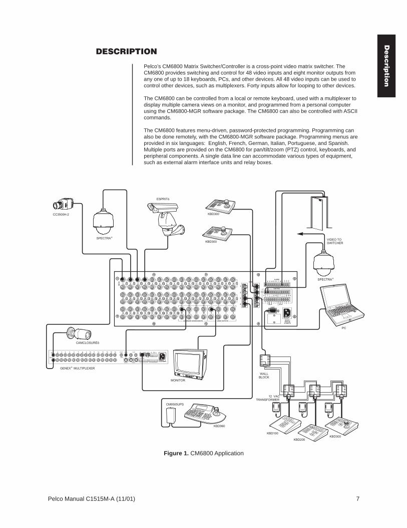
Pelco’s CM6800 Matrix Switcher/Controller is a cross-point video matrix switcher. TheCM6800 provides switching and control for 48 video inputs and eight monitor outputs fromany one of up to 18 keyboards, PCs, and other devices. All 48 video inputs can be used tocontrol other devices, such as multiplexers. Forty inputs allow for looping to other devices.
The CM6800 can be controlled from a local or remote keyboard, used with a multiplexer todisplay multiple camera views on a monitor, and programmed from a personal computerusing the CM6800-MGR software package. The CM6800 can also be controlled with ASCIIcommands.
The CM6800 features menu-driven, password-protected programming. Programming canalso be done remotely, with the CM6800-MGR software package. Programming menus areprovided in six languages: English, French, German, Italian, Portuguese, and Spanish.Multiple ports are provided on the CM6800 for pan/tilt/zoom (PTZ) control, keyboards, andperipheral components. A single data line can accommodate various types of equipment,such as external alarm interface units and relay boxes.
VCR
AUX
MAIN SPOT
SVHS
OUT IN
SVHS
IN COM OUT N N H O C C S
ALARMS
1 2 3 4 5 6 7 8 9 10 11 14 15 16 12 13 110-240V 50/60 Hz
COM 1
1
2
3
4
5
6
7
8
16151413121110987654321
8765484746454039383736353433
32313029282726252423222120191817
41 42 43 44 4321
ALTERNATE SOURCE INPUTS VIDEO OUTPUTS120/230~50/60 HZ
25 WATTS
COM
ALARM1 2 3 4 5 6 7 8
CONTROL
PTZ
OUT
A T+
T-
R+
R-
T+
T-
R+
R-
B
1 2
F3
HZ
75
CM9505UPS
GENEX MULTIPLEXERÆ
2
3
4 5
6
7
1 8
2
3
4 5
6
7
1 8
2
3
4 5
6
7
1 8
2
3
4 5
6
7
1 8
KBD100
KBD200KBD300
WALLBLOCK
12 VACTRANSFORMER
KBD300
ESPRITô
SPECTRAÆ
CAMCLOSUREô
MONITOR
KBD960
PC
KBD300
SPECTRAÆ
CC3500H-2
VIDEO TOSWITCHER
Figure 1. CM6800 Application
De
scrip
tion

8 Pelco Manual C1515M-A (11/01)
KEYBOARDSUp to 16 keyboards from the KBD100/200/300 Series and 2 keyboards from the KBD960/KBR960 Series can be connected to the CM6800, allowing monitoring stations that share acommon monitor to each have a keyboard. Camera positioning can be programmed andcontrolled from the KBD200/300 and KBD960/KBR960 Series keyboards. Keyboard typescan be mixed in a system. Refer to Associated Equipment for keyboard descriptions.
SEQUENCES, MACROS, PRESETS, PATTERNS, AND ZONESSpecial programmed operations include sequences, macros, and camera control, such aspresets, patterns, and zones. All programming (except the scratchpad sequence) ispassword-protected.
A sequence allows operators to see a routine of 72 camera views on any system monitorover and over again. The sequence can be operated automatically or manually. The orderin which the camera views appear and the time each view remains can be programmed.
The CM6800 also provides a scratchpad sequence, which allows a sequence to be runfrom an individual monitor. The scratchpad sequence can be accessed without entering thepassword-protected programming menus.
A macro is a sequence of commands or steps. When a macro is run, the steps programmedinto that macro are performed. Macros can be operated automatically or manually. Automaticoperation can be based on specific times or dates.
The following operations are available only with positionable cameras:
A preset allows operators to direct a PTZ (camera positioning system) to move to apredetermined scene on keyboard command or as a result of an alarm. In addition tomoving the camera, a descriptive title can appear on the screen. The number ofpresets available is determined by the camera positioning system. (Presets are notavailable with the KBD100 keyboard.)
With a pattern operators can program a camera positioning system to move aroundits viewing area in a repeating pattern. The number and time length of patterns varieswith different positioning systems. (Patterns are not available with the KBD100keyboard.)
A zone is a user-defined, physical location to which (1) a label is attached and (2) acamera is associated. When the associated camera is panned through or remainswithin this defined zone, the zone label appears on the monitor. (Zones are notavailable with the KBD100 keyboard.)
INTERFACE CONTROLThe CM6800 interfaces with the following:
• Coaxitron® standard mode (15-bit) and extended mode (32-bit) protocol receivers• Pelco’s D and P protocol receivers (RS-422)• Pelco’s M protocol devices (RS-485)
PARTIONING AND PRIORITYThe CM6800 provides four ways to partition your system:
• Camera to Monitor: Cameras can be assigned to specific monitors for viewing.• Keyboard to Monitor: Keyboards can be assigned to control specific monitors.• Camera to Keyboard:
- Viewing: Keyboards can be assigned view-only access to specific cameras (noPTZ control).
- Control: Keyboards can be assigned PTZ control and viewing access to specificcameras.
The CM6800 provides eight levels of priority control. Each level defines the ability of akeyboard to control a camera positioning system and to access programming screens.
De
scri
pti
on

Pelco Manual C1515M-A (11/01) 9
ALARM INPUTSThe CM6800 can accommodate 136 alarm inputs.
Eight internal alarm inputs are provided on the rear panel of the matrix switcher/controller.These internal alarm inputs are programmable to associate any camera to any input.
The CM6800 provides numerous alarm handling and display options. For example, alarmscan:
• cause a system monitor display to switch automatically to the camera with the alarm.• activate patterns or go to presets.• operate auxiliary outputs.
Also, up to two ALM2064 Alarm Interface Units can be connected to the CM6800. Eachalarm interface unit can handle up to 64 alarms, for a total of 128 external alarms.
AUXILIARY OUTPUTSThree internal auxiliary outputs are provided on the back of the CM6800. Two are relayoutputs, and one is an open collector (TTL) output. You can also connect up to twoREL2064 Relay Interface Units for a maximum capacity of 128 auxiliaries.
Auxiliary outputs are activated at the keyboard (except KBD100).
POWER, MOUNTING METHODSThe CM6800 operates on 120V or 230V, 50/60 Hz. The case mounts in three rack units(5.25 inches or 13.34 cm) of vertical space in a universal mount, such as a 19-inch (48.26cm) equipment bay, or to a wall or tabletop.
CONTINUOUS OPERATING DEVICEThe CM6800 is a self-contained video surveillance system designed specifically for use insecurity applications. As such, the CM6800 is intended for continuous duty operation. Onceinstalled, there are no user or service technician items that require intervention which wouldrequire the system to go off-line or have the power turned off under normal operation.There are two methods for system programming: direct menu control and indirect control,using a Windows®-based setup program supplied by Pelco. Both of these methods arenoninvasive and do not require the cycling of power in order for storage or execution of newsoftware settings. The communication ports use standard low voltage interfaces such asRS-232, RS-422 and RS-485, and all connections and disconnections do not requirerebooting or power cycling. Video connections or changes of termination state do notrequire rebooting or power cycling.
De
scrip
tion

10 Pelco Manual C1515M-A (11/01)
MODELS
CM6800-48X8 Matrix switcher/controller with 48 video inputs and 8 monitor outputs,120/230V, 50/60 Hz
CM6800-48X8-X Matrix switcher/controller with 48 video inputs and 8 monitor outputs,120/230V, 50/60 Hz
ASSOCIATED EQUIPMENTKBD100 Desktop keyboard with full switching and programming capabilities,
+12 VDC or 12V 50/60 Hz
KBD200 Desktop keyboard with full switching and programming capabilities,plus push-button control of PTZ functions, +12 VDC or 12V 50/60 Hz
KBD300 Desktop keyboard with full switching and programming capabilities,plus joystick control of PTZ functions, +12 VDC or 12V 50/60 Hz
KBD960 Full-function desktop variable-speed keyboard; 120V, 50/60 Hz
KBD960-X Same as KBD960, PAL-configured for 230V, 50/60 Hz operation
KBR960 Full-function rack mount variable-speed keyboard; 120V, 50/60 Hz
KBR960-X Same as KBR960, PAL-configured for 230V, 50/60 Hz operation
KBDKIT Wiring kit for connecting KBD100, KBD200, and KBD300 keyboards toremote keyboard port; includes two RJ-45 wall blocks and atransformer to convert 120V, 60 Hz to 12V, 60 Hz for keyboard power
KBDKIT-X Wiring kit for connecting KBD100, KBD200, and KBD300 keyboards toremote keyboard port; includes two RJ-45 wall blocks and atransformer to convert 230V, 50 Hz to 12V, 50 Hz for keyboard power
CM9505UPS Universal Power Supply for KBD960/KBR960 keyboards
MX4000 Genex® Series Multiplexer; available in color or monochrome duplex,and in color or monochrome simplex
CM9760-CDU-T Code distribution unit; 16-channel RS-422 transmit only (transmit wireand ground) distributor; primarily used for connecting up to 16 PTZreceivers in a “star” or “home run” configuration
ALM2064 Alarm interface unit, provides alarm monitoring capabilities for up to 64alarm inputs, 100-240V, 50/60 Hz
REL2064 Relay interface unit, provides 64 relays for operating peripheralequipment, 100-240V, 50/60 Hz
CM9760-MDA Master distribution amplifier with time, date, and title, 120V, 60 Hz
Mo
de
ls

Pelco Manual C1515M-A (11/01) 11
INSTALLATION
Unpack and inspect all parts carefully. The following parts are supplied:
1 CM6800 Switcher/Controller4 10-32 x .750-inch pan head screws4 .500” OD nylon washers1 Power cord4 6-foot (1.8 m) straight data cables with RJ-45 connectors1 6-foot (1.8 m) reversed data cable with RJ-45 connectors4 RJ-45 wall block terminals
MOUNTING
1. Select a suitable location for the CM6800. It occupies 5.25 inches (13.34 cm) ofvertical space, or three rack units (RUs), in a universal mount. The CM6800 must bewithin 6 feet (1.8 m) of a suitable electrical outlet.
Follow proper installation practices and leave 1 RU above and below theCM6800 for ventilation.
Do not connect the power until the installation is complete. Refer to the SystemStart-Up section.
2. The CM6800 is shipped with the rack ears installed at the front. Reposition as neededfor your application. If the ears are not required, remove them.
NOTE: There are no user-serviceable parts inside thisunit. Only authorized servicepersonnel may open theunit.
Figure 2. Installing Rack Ears
3. Use supplied pan head screws and washers to mount the CM6800 in a standard 19-inch (48.26 cm) equipment rack or wood or sheet metal screws to mount against a flatsurface, according to your installation requirements.
Figure 3. Mounting the CM6800 Matrix Switcher/Controller
00615
POSITION BRACKETS FORRACK MOUNTING (FRONT) POSITION BRACKETS FOR
FLUSH MOUNTING(WALL AND TABLE TOP)
POSITION BRACKETS FORRACK MOUNTING (REAR)
NOTE: EACH CM6800 COMESWITH 2 RACK EARS
POSITION BRACKETS FORUNDER-TABLE MOUNTING
00624
Insta
llatio
n

12 Pelco Manual C1515M-A (11/01)
VIDEO SOURCES
The CM6800 offers 48 full-function video inputs which support Coaxitron PTZ control andvideo loss detection. Forty video inputs, labeled 1 through 40, can be used for loopingvideo connections with terminating and unterminating switches on the back panel. Theeight alternate source inputs, labeled 41 through 48, are terminated inputs. They do nothave loop-through connectors or selectable termination switches, but otherwise they offerthe same functionality as video inputs 1 through 40.
All 48 video inputs also provide the ability to view and interface with other devices, such asGenex multiplexers. If control of the device connected to the video input is required,connect a data cable between the multiplexer and the CM6800. Refer to the ConnectingGenex Multiplexers section for instructions on connecting and controlling video from amultiplexer.
00625
Figure 4. CM6800 Video Inputs
1. Connect video cables at the appropriate video input BNC receptacles on the back ofthe CM6800. For best results, use crimp-on BNCs only. Do not use screw-on BNCs;these typically do not provide adequate ground and signal connections.
Refer to Table A for video coaxial wiring requirements.
Table A. Video Coaxial Cable Requirements
Cable Type* Maximum Distance
RG59/U 750 ft (229 m)
RG6/U 1,000 ft (305 m)
RG11/U 1,500 ft (457 m)
* Minimum cable requirements:75 ohms impedanceAll-copper center conductorAll-copper braided shield with 95% braid coverage
Inst
all
ati
on
:V
ide
o S
ou
rce
s

Pelco Manual C1515M-A (11/01) 13
2. On video inputs 1 through 40, set the terminating switches according to your systemrequirements. Video inputs 41 through 48 cannot be used for loop-through connections.
Terminating switches are used to terminate or unterminate the video input. The factorydefault has the switches set in the terminated (75-ohm) position.
If you are connecting only a camera to an input, leave the switch in the terminatedposition.
00626
Figure 5. Connecting Terminated Video Sources
If you are looping the input to another device, set the rear panel switch in theunterminated (Hi-Z) position. Terminate at the final device.
00627
Figure 6. Connecting Looping Video Sources
NOTE: The end point ofany video cable run must beterminated in 75 ohms.
Insta
llatio
n:
Vid
eo
So
urc
es

14 Pelco Manual C1515M-A (11/01)
CONTROL LINES
You cannot connect a Coaxitron camera to the PTZ-A or PTZ-B ports. If your video sourcesare all controlled by Coaxitron, skip this section.
Connect camera control lines to receivers. If any of your video sources are using D or Pprotocol via RS-422 communications, they will connect at the PTZ-A and PTZ-B connectorson the back of the CM6800.
Daisy-chaining (going from one receiver to another) is recommended but not always possible.A maximum of 16 receivers can be daisy-chained from each port. If more than 32 receiversare required for your system, or if you do not want to daisy-chain the receiver connections,use the CM9760-CDU-T. You can connect up to four CM9760-CDU-T units to theCM6800-48X8.
NOTE: D and P protocolreceivers cannot be mixedon the same communicationport but you can use D onone port and P on the other.
Figure 7. PTZ Control Connections
00628
NOTE: After completingsystem installation andpower-up, you must config-ure the CM6800 and thecamera/receiver. Refer tothe System Start-Up section.
Inst
all
ati
on
:C
on
tro
l L
ine
s

Pelco Manual C1515M-A (11/01) 15
MONITORS
The CM6800 supports eight monitors.
1. Install monitors according to the instructions provided with them.
2. Connect the monitor cables at the appropriate video output BNC receptacles on theback of the CM6800.
3. Terminate cables at the monitors. If you are looping to other devices, unterminate allbut the last device.
00629
Figure 8. Connecting Monitors
Insta
llatio
n:
Mo
nito
rs

16 Pelco Manual C1515M-A (11/01)
ALARMS
The CM6800 provides numerous alarm handling options. Refer to the Programming sectionfor a detailed description.
1. Connect wires from the sensors to the respective alarm input points on the connectorsat the back of the CM6800. Each sensor requires two wires – one wire to the alarminput terminal and a return wire to one of the ground terminals on the connector. TheCM6800 supports eight internal alarms.
Alarm sensors can be either N.O. (normally open) or N.C. (normally closed) contacts.The CM6800 is set to N.O. as a factory default.
2. If your system requires more than eight alarms, connect an ALM2064 unit to thesystem. Refer to the M Devices section.
00631
Figure 9. Connecting Alarms
Inst
all
ati
on
:A
larm
s

Pelco Manual C1515M-A (11/01) 17
CONNECTING DEVICES THROUGH THE COMMUNICATION PORTS
The CM6800 Matrix Switcher/Controller provides eight communication ports on the rearpanel for connecting peripheral components. You can connect a wide variety of devices,such as keyboards, a personal computer (for either the CM6800 MGR package or ASCIIcontrol), alarm and relay boxes, and multiplexers. Instructions are provided in this sectionfor the most commonly used connections.
The CM6800 communication ports are labeled COM 1 through 8. Port 1 is available eitheras a DB9 connection, or as an RJ-45 connection. Ports 2 through 8 are RJ-45 connections.In the programming menus these are referred to as serial ports 1 through 8.
PIN 1
PIN 8
COM PORTS 1, 2RS-232, RJ-45
PIN 1
PIN 8
COM PORT 3M, RS-485 , RJ-45
PIN 1
PIN 8
COM PORT 4RS-485, RJ-45
PIN 1
PIN 8
COM PORTS 5, 6RS-485, RJ-45
1-----Rx2-----NC3-----NC45-----GROUND678-----Tx
-----NC
-----NC-----NC
1-----Rx+2-----Rx-345-----GROUND6-----NC7-----Tx-8-----Tx+
-----NC-----NC
1-----Rx+2-----Rx-345-----GROUND6-----NC7-----Tx-8-----Tx+
-----NC-----NC
PIN 1
PIN 8
COM PORTS 7, 8RS-485 (PROGRAMMABLETO RS-232), RJ-45
RS-232 FUNCTIONRS-485 FUNCTION
1-----Rx+2-----Rx-345-----GROUND6-----NC7-----Tx-8-----Tx+
-----KBD 12V-----KBD GROUND
1-----Rx+2-----Rx-345-----GROUND6-----NC7-----Tx-8-----Tx+
-----NC-----NC
1-----Rx2345-----GROUND6-----NC7-----NC8-----Tx
-----NC-----NC-----NC
NC = NO CONNECTION
PIN 5PIN 1
PIN 6 PIN 9
COM PORT 1RS-232,DB9
1-----NC2-----Rx3-----Tx45-----GROUND678-----NC9-----NC
-----NC
-----NC-----NC
Figure 10. Communication Port Connections and RJ-45 Connector Pin-Outs
NOTE: Connection instruc-tions for other peripheraldevices, such as theCM9760-MDA orCM9760-CDU-T, areprovided as Pelco TechnicalTips, available from thePelco web site or from aTechnical Support represen-tative (1-800-289-9100). Formore information, go towww.pelco.com and selectResources. Then selectTechnical Tips.
Insta
llatio
n:
Da
ta P
orts
18 Pelco Manual C1515M-A (11/01)
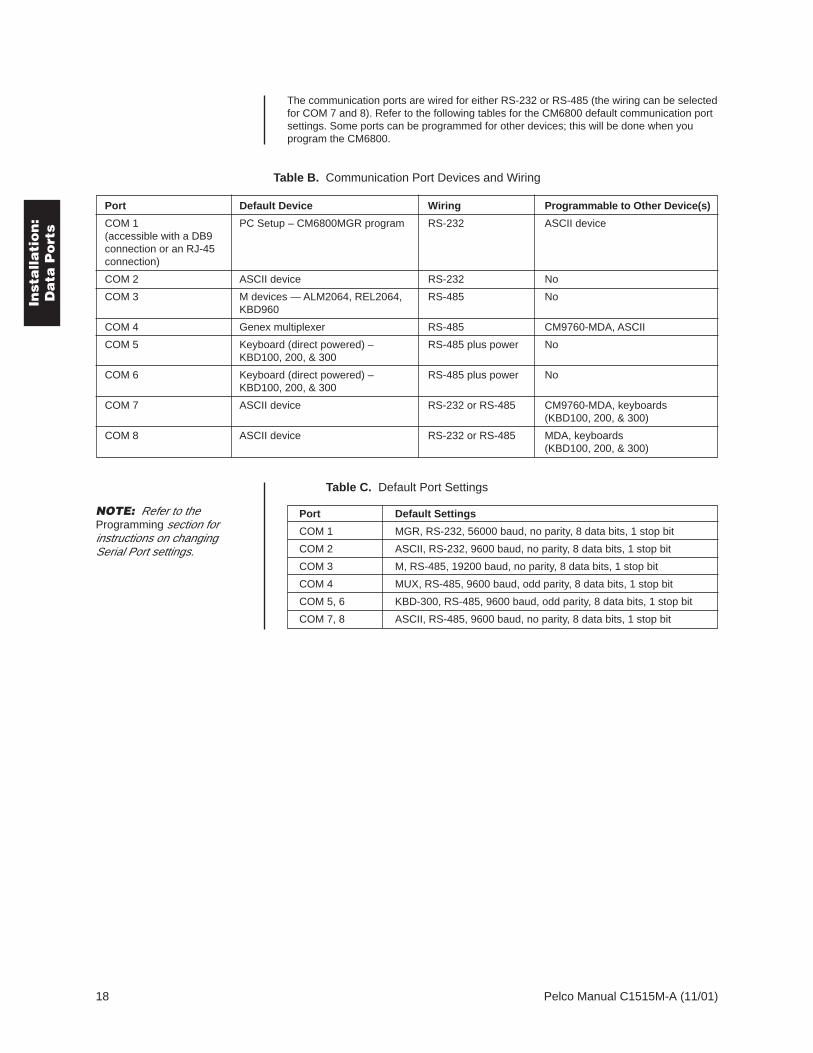
The communication ports are wired for either RS-232 or RS-485 (the wiring can be selectedfor COM 7 and 8). Refer to the following tables for the CM6800 default communication portsettings. Some ports can be programmed for other devices; this will be done when youprogram the CM6800.
Table B. Communication Port Devices and Wiring
Port Default Device Wiring Programmable to Other Device(s)
COM 1 PC Setup – CM6800MGR program RS-232 ASCII device(accessible with a DB9connection or an RJ-45connection)
COM 2 ASCII device RS-232 No
COM 3 M devices — ALM2064, REL2064, RS-485 NoKBD960
COM 4 Genex multiplexer RS-485 CM9760-MDA, ASCII
COM 5 Keyboard (direct powered) – RS-485 plus power NoKBD100, 200, & 300
COM 6 Keyboard (direct powered) – RS-485 plus power NoKBD100, 200, & 300
COM 7 ASCII device RS-232 or RS-485 CM9760-MDA, keyboards(KBD100, 200, & 300)
COM 8 ASCII device RS-232 or RS-485 MDA, keyboards(KBD100, 200, & 300)
Table C. Default Port Settings
Port Default Settings
COM 1 MGR, RS-232, 56000 baud, no parity, 8 data bits, 1 stop bit
COM 2 ASCII, RS-232, 9600 baud, no parity, 8 data bits, 1 stop bit
COM 3 M, RS-485, 19200 baud, no parity, 8 data bits, 1 stop bit
COM 4 MUX, RS-485, 9600 baud, odd parity, 8 data bits, 1 stop bit
COM 5, 6 KBD-300, RS-485, 9600 baud, odd parity, 8 data bits, 1 stop bit
COM 7, 8 ASCII, RS-485, 9600 baud, no parity, 8 data bits, 1 stop bit
NOTE: Refer to theProgramming section forinstructions on changingSerial Port settings.
Inst
all
ati
on
:D
ata
Po
rts

Pelco Manual C1515M-A (11/01) 19
Figure 11. CM6800 Communication Port Connections and Options
COM 1
1
2
3
4
5
6
7
8
87
3231
43
VIDEO OUTPUTS120/230~50/60 HZ
25 WATTS
COM
ALARM1 2 3 4 5 6 7 8
CONTROL
PTZ
OUT
A T+
T-
R+
R-
T+
T-
R+
R-
B
1 2
F3
KBD960
2
3
4 5
6
7
1 8
2
3
4 5
6
7
1 8
2
3
4 5
6
7
1 8
2
3
4 5
6
7
1 8
2
3
4 5
6
7
1 8
2
3
4 5
6
7
1 8
2
3
4 5
6
7
1 8
2
3
4 5
6
7
1 8
2
3
4 5
6
7
1 8
2
3
4 5
6
7
1 8
NOTE: TOTAL NUMBER OFKBD100/200/300 SERIESKEYBOARDS CONNECTEDTO THE CM6800 CANNOTEXCEED 16
COM 7 & 8(RS-485 OR RS-232)PROGRAMMABLE FOR KBD100/200/300 SERIES,ASCII CONTROL, OR CM9760-MDA
COM 4GENEX (RS-485)ALSO PROGRAMMABLE FOR CM9760-MDA OR ASCIIMAX # OF DEVICES = 8
12V 50 HzTRANSFORMER
CM9505UPSPOWER SUPPLY
COM 3M DEVICES (RS-485) MAX # OF DEVICES = 6MAXIMUM DISTANCE FROM CM6800 = 3,940 FT (1,200 M)USING 24 AWG COPPER, UNSHIELDED TWISTED PAIR; 16 pF PER FT (pF =PICO FARADS)
ALM2064NUMBER SUPPORTED = 264 ALARMS X 2 = 128 ALARMS
REL2064NUMBER SUPPORTED = 264 RELAYS X 2 = 128
STRAIGHTCABLES
KBD960NUMBER SUPPORTED = 2
COM 2(RS232)ASCII CONTROL ONLY
ALTERNATE EQUIPMENT
COM 5 & 6 LOCAL KEYBOARDS (RS-485)KBD100/200/300 SERIESMAX # OF DEVICES = 8
2
3
4 5
6
7
1 8
COM 1PC SETUP (RS-232)USE DB9 CONNECTIONOR ALTERNATE RJ-45 CONNECTIONBOTH CANNOT BE USED SIMULTANEOUSLY
RS-232 NULL MODEM CABLE
PC DB9 CONNECTION
PC RJ-45 CONNECTION
Insta
llatio
n:
Pe
riph
era
ls

20 Pelco Manual C1515M-A (11/01)
KBD100, KBD200, AND KBD300 SERIES KEYBOARDSYou can connect up to eight KBD100/200/300 Series keyboards to any of the following ports:
• COM 5 (1 direct-powered keyboard or up to 8 remotely connected keyboards)• COM 6 (1 direct-powered keyboard or up to 8 remotely connected keyboards)• COM 7 (up to 8 remotely connected keyboards)• COM 8 (up to 8 remotely connected keyboards)
The total number of KBD100/200/300 Series keyboards connected to the CM6800 cannotexceed 16.
KBD100, KBD200, and KBD300: Direct-Powered KeyboardsUse COM 5 and 6 (Serial Ports 5 and 6) for direct-powered local keyboards. Each port canpower one KBD100/200/300 Series keyboard.
If you are connecting more than one keyboard to COM 5 or 6, a KBDKIT(-X) is required foreach keyboard. Refer to the KBD100, KBD200, and KBD300: Remote Keyboards section.
1. Using the 25-foot (7.62 m) straight data cable supplied with the keyboard, plug oneend into the RJ-45 connector on the rear of the keyboard.
NOTE: If distance betweenCM6800 and keyboardexceeds 25 feet, useKBDKIT(-X).
00603
Figure 12. Data Cable Plugged into Local Keyboard
2. Plug the other end of the data cable into either COM 5 or 6 on the CM6800.
00604
Figure 13. Data Cables Plugged into COM 5 and 6
Inst
all
ati
on
:K
eyb
oa
rds

Pelco Manual C1515M-A (11/01) 21
3. Set the keyboard DIP switches for the desired address for the local keyboard (refer toFigure 12 and Table D).
Table D. Keyboard Addresses: KBD100/200/300 Series Keyboards
Keyboard Address Switch Settings
1 2 3 4
1 0 OFF OFF OFF OFF
2 1 ON OFF OFF OFF
3 2 OFF ON OFF OFF
4 3 ON ON OFF OFF
5 4 OFF OFF ON OFF
6 5 ON OFF ON OFF
7 6 OFF ON ON OFF
8 7 ON ON ON OFF
Table E. Switch Settings—KBD200/300 Keyboards Only
Keyboard Switch
5 6 7 8
KBD200 OFF OFF OFF (NOT USED) OFF
KBD300 OFF ON or OFF* OFF (NOT USED) OFF
* Switch 6 enables/disables turbo pan (can be switched while keyboard is on).
Insta
llatio
n:
Ke
ybo
ard
s

22 Pelco Manual C1515M-A (11/01)
KBD100, KBD200, and KBD300: Remote KeyboardsUse COM 5, 6, 7, or 8 for remote keyboard connections. Each port can support up to eightKBD100/200/300 Series keyboards. Do not exceed a total capacity of 16 keyboardsconnected to the CM6800.
If using COM 7 or 8, you will need to change the settings (the default setting is for an ASCIIdevice.) Refer to the Programming section for instructions.
1. Select a suitable location for each keyboard and wall block. Wall blocks must be within6 feet (1.8 m) of a suitable electrical outlet. Do not mount the wall blocks yet.
2. Connect each keyboard to a wall block, using the keyboard data cable supplied withthe keyboard.
3. Remove the wall block covers and wire the connections between each wall block.Connect to a final wall block (which will be connected to the CM6800).
Communication to the keyboards is RS-485. Pelco recommends using four-conductor,shielded 18-gauge twisted pairs, such as Belden 9418 or similar cable, that meets orexceeds the basic requirements for EIA RS-485 applications.
4. At each wall block, wire the KBDKIT(-X) transformer to pins 3 and 4. Polarity isunimportant.
5. Replace the cover on the wall block. Secure the wall block to a suitable surface. Adouble-sided sticky pad is provided to mount the wall block.
6. Set the address switches for each keyboard according to Table D.
7. Connect the final wall block to COM 5, 6, 7, or 8 on the CM6800, using a straight datacable (supplied with the CM6800).
NOTE: A KBDKIT orKBDKIT-X is required toconnect remote keyboards.The KBDKIT consists of twoRJ-45 wall blocks and one120V, 60 Hz to 12V, 60Hztransformer. The KBDKIT-Xhas a 230V, 50 Hz to 12V,50 Hz transformer. Use onewall block for each key-board.
00605
Figure 14. Remote Keyboards
NOTE: If you do notconnect keyboards toCOM 7 or 8, either port canbe used for a CM9760-MDAor an ASCII device.Connection instructions forCM9760-MDA are providedas a Pelco Technical Tip.Refer to the note on page17. For ASCII devices, referto the documentation thatcomes with the equipment.
Inst
all
ati
on
:K
eyb
oa
rds

Pelco Manual C1515M-A (11/01) 23
M DEVICESM protocol devices (KBD960/KBR960 keyboards, ALM2064 Alarm Interface Units, andREL2064 Relay Interface Units) can be connected to COM 3 on the CM6800.
If only one device is to be connected to COM 3, use the instructions for that device in thefollowing sections.
If more than one device is to be connected to COM 3, refer to the Multiple M Devicessection.
Connect M devices to the CM6800 with straight cables. Four straight cables and onereversed cable are supplied with the CM6800 (save the reversed cable for connecting aGenex Multiplexer, if applicable).
M Devices AddressingEach M device connected to the CM6800 must have a unique local address within a rangeof 1-16. Use the hardware DIP switches to set the appropriate ALM2064 and REL2064local addresses. Specify the appropriate KBD960/KBR960 local address through thekeyboard Setup Mode after you complete the system installation (refer to the System Start-Up section).
For use with the CM6800, Pelco recommends numbering M devices in a sequential order.In a sample application, with two of each M device, you might assign local addresses asfollows:
M device local addresses: Default Recommended for CM6800
KBD960/KBR960: 1 1, 2REL2064: 1 3, 4ALM2064: 1 5, 6
Figure 15. RJ-45 Cable Types
COMPARED "COLOR RUN"IS IN SAME DIRECTION
COMPARED "COLOR RUN"IS IN OPPOSITE DIRECTION
BROWN BROWN
STRAIGHT CABLE
BROWN BROWN
REVERSED CABLE
TO IDENTIFY A CABLE TYPE, PHYSICALLY ORIENT THE RJ-45 CABLE AS DEPICTED IN THE ILLUSTRATIONS. ORIENT THE CONNECTORS SIDE BY SIDE. TAB SIDE DOWN. USE THE COLOR RUN OF THE WIRES TO DETERMINE CABLE TYPE.
00612
NOTE: If you wish to usethe partitioning and priorityfeatures of the CM6800, youmust number KBD960/KBR960 keyboards within arange of 1-8.
Insta
llatio
n:
M D
evic
es

24 Pelco Manual C1515M-A (11/01)
00607
NOTE: After completingsystem installation andpower-up, you must config-ure the KBD960/KBR960settings. Refer to the SystemStart-Up section.
Connecting a Single KBD960/KBR960 KeyboardTo connect a single KBD960/KBR960 Keyboard to the CM6800:
1. Connect the keyboard to the CM9505UPS using the straight cable supplied with thekeyboard.
2. Connect the CM9505UPS to COM 3 on the CM6800 using the 6-foot (1.8 m) straightdata cable supplied with the CM6800.
Figure 16. Connecting a KBD960/KBR960 to the CM6800
Inst
all
ati
on
:M
De
vic
es

Pelco Manual C1515M-A (11/01) 25
Connecting a Single ALM2064 Alarm Interface UnitTo connect a single ALM2064 Alarm Interface Unit:
1. Connect the ALM2064 OUT port to COM 3 on the CM6800 using the 6-foot (1.8 m)straight data cable supplied with the CM6800.
2. Set SW2, DIP switches 1-8 to the appropriate positions for the local address (defaultaddress setting is 1). Refer to the ALM2064 Alarm Interface Unit Installation/OperationManual for instructions.
00608
Figure 17. Connecting a Single ALM2064 Alarm Interface Unit
Insta
llatio
n:
M D
evic
es

26 Pelco Manual C1515M-A (11/01)
Connecting a Single REL2064 Relay Interface UnitTo connect a single REL2064 Relay Interface Unit:
1. Connect the REL2064 OUT port to COM 3 on the CM6800 using the 6-foot (1.8 m)straight data cable supplied with the CM6800.
2. Set SW2, DIP switches 1-8 to the appropriate positions for the local address (defaultaddress setting is 1). Refer to the REL2064 Relay Interface Unit Installation/OperationManual for instructions.
00609
Figure 18. Connecting a Single REL2064 Relay Interface Unit
Inst
all
ati
on
:M
De
vic
es

Pelco Manual C1515M-A (11/01) 27
REL2064
ALM2064KBD960
RS-485
STRAIGHT CABLE(SUPPLIED)
STRAIGHT CABLE (SUPPLIED)
COM 1
1
2
3
4
5
6
7
8
16
876
3231
43
VIDEO OUTPUTS120/230~50/60 HZ
25 WATTS
COM
ALARM1 2 3 4 5 6 7 8
CONTROL
PTZ
OUT
A T+
T-
R+
R-
T+
T-
R+
R-
B
1 2
F3
KBD960RJ-45 PIN-OUTS
1 Tx+2 Tx-3 4 5 6 7 Rx-8 Rx+
ALM2064RJ-45 PIN-OUTS
1 Tx+2 Tx-3 4 5 6 7 Rx-8 Rx+
REL2064RJ-45 PIN-OUTS
1 Tx+2 Tx-3 4 5 6 7 Rx-8 Rx+
CM6800 COM 3RJ-45 PIN-OUTS
1 Rx+2 Rx-3 4 5 GND6 7 Tx-8 Tx+
CM9505UPS
STRAIGHT CABLE(SUPPLIED)
COM 3DEFAULT SETTINGS: M, RS-485, 19200 BAUD, NO PARITY, 8 DATA BITS, 1 STOP BITMAX # OF DEVICES = 6MAXIMUM DISTANCE FROM CM6800 = 3,940 FT (1,200 M)USING 24 AWG COPPER, UNSHIELDED TWISTED PAIR; 16pF PER FT (pF = PICOFARADS)
Figure 19. Connecting Multiple M Devices – Local Connection
Multiple M DevicesMultiple M devices (KBD960/KBR960, ALM2064, and REL2064) can be connected to COM3 on the CM6800, either as local devices or remote devices (when connecting twoKBD960/KBR960 keyboards to the CM6800, you must use a remote connection).
MULTIPLE M DEVICES: LOCAL CONNECTION1. If you are connecting a KBD960/KBR960, connect it to the CM9505UPS with the
straight cable supplied with the keyboard. Then connect the CM9505UPS to the INport on the next unit (either the ALM2064 or the REL2064) with a 6-foot (1.8 m)straight cable (supplied with the CM6800).
2. Connect each ALM2064 and REL2064 unit to the next unit with a 6-foot (1.8 m) straightcable (supplied with the CM6800) from the OUT port to the IN port on the next unit. Youcan connect a maximum of two ALM2064 units and two REL2064 units to the CM6800.
3. Connect the last unit to the CM6800 with a 6-foot (1.8 m) straight cable (supplied withthe CM6800) from the OUT port to COM 3 on the CM6800.
Insta
llatio
n:
M D
evic
es

28 Pelco Manual C1515M-A (11/01)
MULTIPLE M DEVICES: REMOTE CONNECTIONUse a remote connection when the distance from the CM6800 is greater than 6-feet (1.8 m).
1. Connect each ALM2064 and REL2064 unit to a wall block with a 6-foot (1.8 m) straightcable (supplied with the CM6800). You can connect a maximum of two ALM2064 unitsand two REL2064 units to the CM6800.
2. If you are connecting a KBD960, connect it to the CM9505UPS with the straight cablesupplied with the keyboard. Then connect the CM9505UPS to a wall block with a6-foot (1.8 m) straight cable (supplied with the CM6800). You can connect a maximumof two KBD960 keyboards to the CM6800.
3. Connect the wall blocks to a final wall block. If additional wall blocks are needed, orderpart number CON12J008Z03G0Z.
4. Connect the terminal wall block to COM 3 on the CM6800 using a 6-foot (1.8 m)straight cable (supplied with the CM6800).
ALM2064 REL2064KBD960
STRAIGHT CABLE(SUPPLIED)
STRAIGHT CABLETO CM9505UPS(SUPPLIED)
CONNECT THROUGHTHE “OUT” PORTKBD960
RJ-45 PIN-OUTS
1 Tx+2 Tx-34567 Rx-8 Rx+
ALM2064RJ-45 PIN-OUTS
1 Tx+2 Tx-34567 Rx-8 Rx+
REL2064RJ-45 PIN-OUTS
1 Tx+2 Tx-34567 Rx-8 Rx+
COM 1
1
2
3
4
5
6
7
8
16
876
3231
43
VIDEO OUTPUTS120/230~50/60 HZ
25 WATTS
COM
ALARM1 2 3 4 5 6 7 8
CONTROL
PTZ
OUT
A T+
T-
R+
R-
T+
T-
R+
R-
B
1 2
F3
CONNECT THROUGHTHE “OUT” PORT
3
4
2
1
5
6
7
8
3
4
2
1
5
6
8
7
8
5
6
7
4
1
3
2
3
4
1
2
8
6
7
5
STRAIGHT CABLE(SUPPLIED)
CM6800 COM 3RJ-45 PIN-OUTS
1 Rx+2 Rx-345 GND67 Tx-8 Tx+
COM 3DEFAULT SETTINGS:M, RS-485, 19200 BAUD, NO PARITY, 8 DATA BITS, 1 STOP BITMAX # OF DEVICES = 6MAXIMUM DISTANCE FROM CM6800 = 3,940 FT (1,200 M)USING 24 AWG COPPER, UNSHIELDED TWISTED PAIR; 16pF PER FT (pF = PICOFARDS)
Figure 20. Connecting Multiple M Devices – Remote Connection
Inst
all
ati
on
:M
De
vic
es

Pelco Manual C1515M-A (11/01) 29
CONNECTING A PCThe CM6800 provides PC-based setup and programming software that facilitates completeswitcher programming and configuration. Refer to the CM6800-MGR Quick Start Guide forinstructions on using the software.
Connect a PC to the CM6800 to access the CM6800-MGR software or to downloadupgrades to the software. You can connect a PC to the CM6800 through either a DB9 portor an RJ-45 port. You cannot use both ports simultaneously.
1. Using a null modem cable (user-supplied), plug one end into the DB9 COM 1 port onthe PC.
2. Plug the other end of the cable into the DB9 COM 1 port of the CM6800.
NULL MODEM CABLE
CM6800 COM 1DB9 PIN-OUTS
PIN 2 = RX INPIN 3 = TX OUTPIN 5 = GND
PIN 5PIN 1
PIN 6 PIN 9
PC COM 1DB9 PIN-OUTS
PIN 2 = RX INPIN 3 = TX OUTPIN 5 = GND
00613
CM6800 COM 1RJ-45 PIN-OUTS
PIN 1 = RX INPIN 5 = GNDPIN 8 = TX OUT
PC COM 1DB9 PIN-OUTS
PIN 2 = RX INPIN 3 = TX OUTPIN 5 = GND
RJ-45 WALL BLOCKAND STRAIGHT CABLESUPPLIED WITH CM6800
2 3
4 5 6 7
1 8
MODIFIED NULL MODEM CABLE(USER-SUPPLIED)
PC COM 1
CM6800 COM 1
00992
Figure 21. PC Connection to DB9 Port
OR
1. Using a modified null modem cable (user-supplied), connect the DB9 COM 1 port onthe PC to an RJ-45 wall block (supplied with the CM6800 Matrix Switcher).
The modified null modem cable should be cut at one end, so that you can connect thewires directly to the wall block pins.
2. Using a 6-foot (1.8 m) data cable (supplied with the CM6800 Matrix Switcher), connectthe wall block to the RJ-45 COM 1 port of the CM6800.
Figure 22. PC Connection to RJ-45 Port
NOTE: You can alsoconnect an ASCII devicethrough COM 1, 2, 7, or 8.Using an ASCII devicethrough COM 1 requires achange in serial portsettings. Refer to theProgramming section forinstructions.
Insta
llatio
n:
PC
Co
nn
ec
tion

30 Pelco Manual C1515M-A (11/01)
CONNECTING GENEX MULTIPLEXERSUse COM 4 to connect up to eight Genex Multiplexers to the CM6800.
1. Connect the COM IN port of the multiplexer to COM 4 on the CM6800, using the6-foot (1.8 m) reversed data cable supplied with the CM6800.
One reversed cable and four straight cables are supplied with the CM6800. Use thereversed cable for connecting the Genex multiplexer to the CM6800.
A straight data cable is supplied with the Genex multiplexer. Use this cable forconnecting a second Genex multiplexer to the first multiplexer, if necessary.
2. Connect the MAIN monitor output from the multiplexer to any of the 48 camera inputson the CM6800.
3. Connect cameras to the multiplexer and then loop them to the CM6800. Refer to theMX4000 Genex Series Simplex and Duplex Multiplexers Installation/Operation Manualfor detailed camera connection instructions. Terminate the video loop at the CM6800.
4. If required, you can connect a total of eight Genex multiplexers through COM 4. Daisy-chain the multiplexers by connecting a straight data cable from the COM OUT port onthe first multiplexer to the COM IN port on the second multiplexer; connect the COMOUT port on the second multiplexer to the COM IN port on the third multiplexer.Continue to the eighth multiplexer, if necessary.
Refer to the System Start-Up section for additional configuration steps required when usinga Genex Multiplexer.
NOTE: If you do not con-nect multiplexers to COM 4,you can connect aCM9760-MDA or an ASCIIdevice through COM 4. Us-ing either device requires achange in serial port set-tings. Refer to the Program-ming section.
Figure 23. Connecting Genex Multiplexers
COM 1
1
2
3
4
5
6
7
8
16151413121110987654321
8765484746454039383736353433
32313029282726252423222120191817
41 42 43 44 4321
ALTERNATE SOURCE INPUTS VIDEO OUTPUTS120/230~50/60 HZ
25 WATTS
COM
ALARM1 2 3 4 5 6 7 8
CONTROL
PTZ
OUT
A T+
T-
R+
R-
T+
T-
R+
R-
B
1 2
F3
HZ
75
VCR
AUX
MAIN SPOT
SVHS
OUT IN
SVHS
IN COM OUT N N
H O C C S
ALARMS
1 2 3 4 5 6 7 8 9 10 11 14 15 16 12 13 110-240V 50/60 Hz
VCR
AUX
MAIN SPOT
SVHS
OUT IN
SVHS
IN COM OUT N N
H O C C S
ALARMS
1 2 3 4 5 6 7 8 9 10 11 14 15 16 12 13 110-240V 50/60 Hz
VCR
AUX
MAIN SPOT
SVHS
OUT IN
SVHS
IN COM OUT N N
H O C C S
ALARMS
1 2 3 4 5 6 7 8 9 10 11 14 15 16 12 13 110-240V 50/60 Hz
GENEX MULTIPLEXERRJ-45 PIN-OUTS
Rx+ Rx- NC NC GROUND NC Tx- Tx+
CM6800 COM 4RJ-45 PIN-OUTS
GENEX MULTIPLEXERS-8 MAXIMUM
GENEX MULTIPLEXER
GENEX MULTIPLEXER
GENEX MULTIPLEXER
1 2 3 4 5 6 7 8
REVERSED CABLE
MONITOR SIGNAL OUT
1 2 3 4 5 6 7 8
Rx+ Rx-
12VAC (OUT) 12VAC
GROUND NC Tx- Tx+
(OUT)
STRAIGHT CABLE
STRAIGHT CABLE
00616
Inst
all
ati
on
:G
en
ex

Pelco Manual C1515M-A (11/01) 31
LOCAL AUXILIARIES
The CM6800 provides three local auxiliary (AUX) outputs on the rear panel for controllingVCRs, printers, and other devices. These outputs can be activated directly from a keyboardby using the F1, F2, and F3 function keys, or they can be activated by an alarm (deter-mined by programming). Both relay contacts and TTL outputs are used.
In addition, you can connect up to two REL2064 Relay Interface Units to the CM6800. Notethat since operation of the three internal auxiliary relays on the CM6800 will also operatethe first three relays on the external unit, the maximum capacity of the system may belimited to 128 auxiliaries (depending on how you number the external relays). Refer to theConnecting a Single REL2064 Relay Interface Unit section for connection instructions.
CONNECTING RELAY CONTACTS – AUX 1 AND 2AUX 1 and 2 are dry contact relay outputs. Refer to Figure 25 for wiring details. Terminalconnections are provided for both normally open (N.O.) and normally closed (N.C.) contacts.
Do not exceed the voltage and current ratings for the relay contacts.
You will need to provide an external power source to operate your device. In most casesyou will also need an external current limiting resistor. The formula for calculating theresistor value is given in Figure 25.
00617
Figure 24. Wiring the AUX 1 and 2 (Relay) Outputs
Insta
llatio
n:
Au
xilia
ries

32 Pelco Manual C1515M-A (11/01)
CONNECTING THE OPEN COLLECTOR OUTPUT – F3 (TTL)F3 is a TTL open collector output. This output provides a path to ground to control the lowvoltage trigger input on many devices. It can control higher voltage control inputs viaisolation relays. Refer to Figure 26 for wiring details.
Do not exceed the voltage and current ratings for the TTL output.
An external pull-up resistor is usually necessary. The formula for calculating the resistorvalue is given in Figure 26.
00618
Figure 25. Wiring the F3 (TTL) Output
Inst
all
ati
on
:A
ux
ilia
rie
s

Pelco Manual C1515M-A (11/01) 33
SYSTEM START-UP
After completing the system installation, follow the procedure below to start proper systemoperation. Skip any “system-specific” steps that do not apply to your system setup.
POWER-UP THE SYSTEM
Plug the CM6800 power cord into a 120/230V, 50/60 Hz power source. Plug in and turn onall devices connected to the CM6800.
Once the system is powered-up you will see video from camera 1 and the following time/date stamp on all system monitors:
Figure 26. CM6800 Time/Date Stamp on Monitor
The time stamp will be advancing in one-second increments. Wait five seconds beforeproceeding.
INITIALIZE KEYBOARDS
You must specify a monitor for each keyboard after your first power-up or any time power iscycled to the keyboard or the CM6800.
Always allow five seconds to elapse before specifying a monitor.
1. Enter a number (1-8) corresponding to the monitor output that is feeding the monitoryou are viewing.
2. Press the MON key. The keyboard LED displays the number you entered. This alsoconfirms successful communication between the keyboard and the CM6800. If thekeyboard LED does not display the monitor number, repeat 1 and 2.
If you are unable to select the monitor, refer to the Troubleshooting section.
CONFIGURE THE SYSTEM
If necessary, configure the CM6800 and associated equipment to your specific application.The CM6800 is shipped from the factory with default programming settings. If the defaultsare acceptable, the CM6800 can be operated without any user programming. However, youmay want to program the basic system settings, such as time and date, and camera titles.In addition, some or all of the following configuration steps may be necessary, dependingon your system.
Configure the CM6800 through Programming mode. Refer to the Programming section fordetailed instructions.
TIME AND DATEAccess the Time & Date programming screen to set the time and date, and select the time/date format option.
00620
Syste
mS
tart-U
p

34 Pelco Manual C1515M-A (11/01)
CAMERA TITLESBy default each camera is titled “CAM #” (# = camera number from 1-48). Access theCamera programming screen to change the camera titles.
VIDEO SOURCESExtended Coaxitron protocol receivers can be operated without any programming changes.For other receiver control protocols, access the Camera programming screen to select thecontrol type for the device connected to each video input. Control can be through standardmode Coaxitron, extended mode Coaxitron, RS-422 PTZ through Port A or Port B on therear panel, or through a Genex Multiplexer.
For RS-422 PTZ control you must configure the CM6800:
• Access the Camera programming screen to identify the receiver control type(PTZ-A or PTZ-B) and to select the appropriate camera port address. Thecamera port address must match the address setting configured through thecamera/receiver DIP switch settings.
• Access the Port programming screen to select the appropriate communicationtype (P or D) for serial ports 9 (PTZ-A) and 10 (PTZ-B). Default settings for PTZ-A and PTZ-B: PTZ-P, RS-422, 4800 baud, no parity, 8 data bits, 1 stop bit.
You must also configure the camera/receiver. Refer to the appropriate camera/receiverinstallation manual for configuration and address settings.
ALARMSThe CM6800 is shipped from the factory with the alarm contact enable field set to OFF. Touse the alarm features, access the Alarm programming screens to enable the alarmcontact.
COMMUNICATION PORTSIf you are using any communication port for a device not specified by the default setting,you must access the Port programming screen to change the settings.
Table F. Default Port Settings
Port Default Settings
COM 1 MGR, RS-232, 56000 baud, no parity, 8 data bits, 1 stop bit
COM 2 ASCII, RS-232, 9600 baud, no parity, 8 data bits, 1 stop bit
COM 3 M, RS-485, 19200 baud, no parity, 8 data bits, 1 stop bit
COM 4 MUX, RS-485, 9600 baud, odd parity, 8 data bits, 1 stop bit
COM 5, 6 KBD-300, RS-485, 9600 baud, odd parity, 8 data bits, 1 stop bit
COM 7, 8 ASCII, RS-485, 9600 baud, no parity, 8 data bits, 1 stop bit
PTZ-A (Port 9) PTZ-P, RS-422, 48 baud, no parity, 8 data bits, 1 stop bit
PTZ-B (Port 10) PTZ-P, RS-422, 48 baud, no parity, 8 data bits, 1 stop bit
KBD960/KBR960 KEYBOARDConfigure the KBD960/KBR960 settings.
1. Set DIP switch 2 to the ON position.
2. Enter Setup Mode. Set the local address (1-8). (Note: the baud rate is set by default to19200.) Each M device connected to the CM6800 must have a unique local address.Refer to the KBD960/KBR960 Keyboard Installation/Operation Manual for detailedsetup instructions.
3. Return DIP switch 2 to the OFF position.
4. Press the EXIT icon on the keyboard LCD screen.
Sys
tem
Sta
rt-U
p

Pelco Manual C1515M-A (11/01) 35
GENEX MULTIPLEXERAccess the Camera programming screen and specify MUX control for all camerasconnected to the CM6800 through the Genex Multiplexer.
Access the CM6800 Camera programming screen to configure the following camera controloptions for each camera connected to the CM6800 through the Genex Multiplexer:
• CONTROL: MUX• PORT ADDRESS: assign the appropriate address. The port address must match
the “Unit ID” assigned through the Genex programming screens.
You must also configure the Genex Multiplexer. Refer to the MX4000 Genex SeriesSimplex and Duplex Multiplexers Installation/Operation Manual (C1920M-B) for instructionson accessing the Advanced System Setup programming screen. Select the followingoptions:
• SPOT MONITOR DISPLAY: TRACK MAIN• UNIT ID (must match the port address assigned through the CM6800)• COMM. TYPE: SLAVE (each multiplexer connected to the CM6800 must be in
slave mode)
MONITOR COLOR ADJUSTMENT:Once you have connected all devices and powered the system, use the CM6800 color barsas a reference tool for adjusting the color on each monitor.
1. Enter 9999.2. Press the CAM key. Broadcast quality color bars appear on the monitor.3. Adjust color on each monitor as necessary until the color bars match the following
color order on the monitor (for black and white monitors you can use the color bars toadjust brightness):
00630
Figure 27. CM6800 Color Bars
PROGRAM PRESETSProgram presets as necessary for your system. Refer to the appropriate keyboard manualfor instructions.
ADDITIONAL PROGRAMMINGRefer to the Programming section for complete instructions on programming the CM6800.
Syste
mS
tart-U
p

36 Pelco Manual C1515M-A (11/01)
PROGRAMMING THE CM6800
The CM6800 is shipped from the factory with default programming settings. If the defaultsare acceptable, the CM6800 can be operated without any user programming. However, youmay want to program the following basic system settings:
• Time and date
• Camera titles
• PTZ control via hardwire data connections
• Alarm contactsAlarms must be enabled before they are functional.
• Access/PartitioningAll access is set to YES by factory default.
• Communication portsIf you connect your system as illustrated in the Quick Start Guide, you mustchange the settings for Port 7 or 8 in order to connect remote keyboards.
You can further customize your system with a wide range of programming options, such as:
• select the language displayed on programming screens
• establish monitor group sequences
• set monitor display options
• set alarm handling options
• assign logical camera numbering
• change password
• set auxiliary options
CUSTOMIZING THE CM6800
Pelco provides two options for programming the CM6800 to your specifications:
• Password-protected, on-screen programming screens accessible directly fromthe Matrix Switcher
• PC-based CM6800-MGR software
Refer to the CM6800-MGR Quick Start Guide for instructions on accessing andusing this software to program your system.
NOTE: Pelco strongly recommends uploading your programming settingsto the CM6800-MGR to save settings in the event of an accidental reset.
NOTE: The CM6800 allowssystem programming fromonly one monitor at a time. Ifprogramming from theCM6800-MGR is sent to theCM6800 at the same timethat you are programmingfrom a monitor screen, thesystem will exit the on-screenprogramming function.
Pro
gra
mm
ing

Pelco Manual C1515M-A (11/01) 37
ACCESS PROGRAMMING MODE FROM THE CM6800
Figure 28. CM6800 Password Screen
Figure 29. CM6800 Programming Main Menu
If necessary, select the appropriate language.
1. Navigate to the language displayed below the menu options.
2. Scroll through the languages and select the language appropriate for your system.
OPTIONS:ENGLISHESPANOLDEUTSCHFRANCAISPORTUGUESEITALIANO
3. Navigate to the RETURN field and navigate left or right to return to the Main Menu.
PELCO SWITCHERMODEL CM6800
MAIN MENU
1 CAMERA2 LOGICAL CAMERA3 MONITOR4 ACCESS5 TIME & DATE6 PORT7 PRIORITY8 SEQUENCE9 MACRO
10 ALARM CONTACTS11 EVENT TIMER12 SET AUXILIARY13 SET PASSWORD14 ABOUT CM6800
ENGLISH
RETURN
00654
PELCO VIDEO SWITCHERMODEL CM6800
PASSWORD TO MAIN MENU*******
SCRATCHPAD SEQUENCE
RETURNMACRO STATUS VIEW
NOTE: If you have not
already done so, enter the
monitor number and press
the MON key to select the
monitor. On the KBD960/
KBR960, the Camera menu
appears on the LCD display.
Press to exit the
Camera menu.
DEF
MENU
PGM
The Main Menu appears.
The Password screen appears on the monitor.
KBD100/200/300 Keyboards
1. Press the PGM key.
KBD960/KBR960 Keyboards
1. Select .
2. Select .
3. Enter the Define PIN (Default: 1234).
4. Select .
5. Select .
At the ******* prompt, enter the DEFAULT PASSWORD: 2899100
Pro
gra
mm
ing

38 Pelco Manual C1515M-A (11/01)
Exit Programming Mode
NAVIGATE AND SELECT OPTIONS/FIELD ENTRIES INPROGRAMMING MODEDuring programming, a menu appears on the monitor screen. The currently selected field blinks.Use the following keys or joystick on your keyboard to navigate the programming screens.
PGM
PGM
Function
Navigate programming screens.
PREV NEXTMAC
HOLD
Access a screen from the MainMenu (or from a submenu).
Keyboard
KBD100Use the sequence and macro keys.
Left Right Up Down
KBD200Use the Pan/Tilt positioning keys.
Left Right Up Down
KBD300Use the joystick.
Left Right Up Down
KBD960/KBR960Use the joystick. (See above icons)
OR
Select the appropriate icon on theKBD960/KBR960 LCD SCREEN.
Left Right Up Down
All Keyboards1. Navigate down to the desired menu
option.
2. Navigate left or right to select the menuoption.
OR
1. Using the numerical keypad, enter thenumber of the menu option.
2. Press F1 on the KBD100/200/300
keyboard or select on the KBD960/KBR960 keyboard.
KBD100/200/300 Keyboards
To return to active video you can:
• Press the PGM key once whilein the Main Menu.
• Press the PGM key twice fromanywhere else in the program-ming screens.
• Navigate to the RETURN fieldand navigate left or right toreturn to the previous screen ormenu.
KBD960/KBR960 Keyboards
To return to active video you can:
• Select once while in the MainMenu.
• Select twice from anywhere else inthe programming screens.
• Navigate to the RETURN field andnavigate left or right to return to theprevious screen or menu.
TIP: To access a screen
or enter a value, press a
number key on the keyboard
and then press F1
(KBD100/200/300) or select
(KBD960/KBR960).
Pro
gra
mm
ing
Pelco Manual C1515M-A (11/01) 39
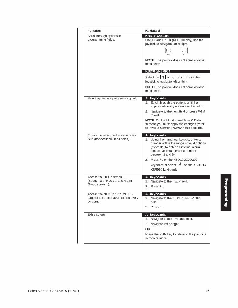
Function
Scroll through options inprogramming fields.
Select option in a programming field.
Enter a numerical value in an optionfield (not available in all fields).
Access the HELP screen(Sequences, Macros, and AlarmGroup screens).
Access the NEXT or PREVIOUSpage of a list (not available on everyscreen).
Keyboard
KBD100/200/300Use F1 and F2. Or (KBD300 only) use thejoystick to navigate left or right.
NOTE: The joystick does not scroll optionsin all fields.
KBD960/KBR960
Select the or icons or use thejoystick to navigate left or right.
NOTE: The joystick does not scroll optionsin all fields.
All keyboards1. Scroll through the options until the
appropriate entry appears in the field.
2. Navigate to the next field or press PGMto exit.
NOTE: On the Monitor and Time & Datescreens you must apply the changes (referto Time & Date or Monitor in this section).
All keyboards1. Using the numerical keypad, enter a
number within the range of valid options(example: to enter an internal alarmcontact you must enter a numberbetween 1 and 8).
2. Press F1 on the KBD100/200/300
keyboard or select on the KBD960/
KBR960 keyboard.
All keyboards1. Navigate to the HELP field.
2. Press F1.
All keyboards1. Navigate to the NEXT or PREVIOUS
field.
2. Press F1.
All keyboards1. Navigate to the RETURN field.
2. Navigate left or right.
OR
Press the PGM key to return to the previousscreen or menu.
F1 F2
Exit a screen.
Pro
gra
mm
ing

40 Pelco Manual C1515M-A (11/01)
ABOUT CM6800The About CM6800 screen displays system version levels.
ABOUT CM6800
CODE:MONITOR FPGA:COAX FPGA:CPU FPGA:VIDEO FPGA:
RETURN
FONTS
BOOTROMEID#:
ITALIAN:PORTUGUESE:FRENCH:GERMAN:SPANISH:ENGLISH:
VERSIONVER MONVER CXTCER CPUVER VID VER FNT
VER ITAVER PORVER FREVER GERVER SPAVER ENG
VER V1.01113-145119079400000
V1.03V1.02V1.02V1.02AV1.02 V1.02
V1.02V1.02V1.02V1.02V1.02V1.02
PELCO SWITCHERMODEL CM6800
MAIN MENU
1 CAMERA2 LOGICAL CAMERA3 MONITOR4 ACCESS5 TIME & DATE6 PORT7 PRIORITY8 SEQUENCE9 MACRO
10 ALARM CONTACTS11 EVENT TIMER12 SET AUXILIARY13 SET PASSWORD14 ABOUT CM6800
ENGLISH
RETURN
00654
Figure 30. Access the About CM6800 Screen
ACCESS (SYSTEM PARTITIONING)The CM6800 supports the following system partitioning to control switching system access:
Keyboard to Monitor: Restrict a keyboard from accessing selected monitors.
Camera to Keyboard: Restrict a keyboard from calling selected cameras to monitors. Orvideo viewing only: permit the viewing of selected cameras whilepreventing pan and tilt control.
Camera to Monitor: Restrict the viewing of selected cameras on selected monitors.
All system access is set to YES by default.
Keyboard to Monitor AccessUse the Keyboard to Monitor Access screen to assign keyboards control of specificmonitors.
NOTE: To use partitioningfor keyboards, all keyboardaddresses must be within arange from 1-8.
Figure 31. Access the Keyboard to Monitor Access Screen
PORT: Select the COM port number for which you are programming accesscontrol (1-8).
In each monitor row specify the access allowed for each keyboard (address 1-8) to controleach specific monitor (1-8).
OPTIONS:Y = Yes; control is allowedN = No; control is not allowed
PELCO SWITCHERMODEL CM6800
MAIN MENU
1 CAMERA2 LOGICAL CAMERA3 MONITOR4 ACCESS5 TIME & DATE6 PORT7 PRIORITY8 SEQUENCE9 MACRO
10 ALARM CONTACTS11 EVENT TIMER12 SET AUXILIARY13 SET PASSWORD14 ABOUT CM6800
ENGLISH
RETURN
00654
ACCESS
1 KEYBOARD TO MONITOR2 CAMERA TO KEYBOARD3 CAMERA TO MONITOR 1-8
RETURN
00636
KEYBOARD TO MONITOR ACCESS
PORT 7
MON KEYBOARD
1 2 3 4 5 6 7 8
1 Y Y Y Y Y Y Y Y2 Y Y Y Y Y Y Y Y3 Y Y Y Y Y Y Y Y4 Y Y Y Y Y Y Y Y5 Y N Y Y Y Y Y Y6 Y N Y Y Y Y Y Y7 Y N Y Y Y Y Y Y8 Y N Y Y Y Y Y Y
00651
NOTE: If you connect anASCII keyboard/device tothe CM6800 (COM port 1, 2,4, 7, or 8), you can connectonly one keyboard to a port.Specify access in the firstcolumn only (address 1).
Ac
ce
ssP
rog
ram
min
g

Pelco Manual C1515M-A (11/01) 41
Camera To Keyboard AccessUse the Camera to Keyboard Access screen to assign keyboards full control or view-onlycontrol of specific cameras.
Figure 32. Access the Camera to Keyboard Access Screen
PORT: Select the COM port number for which you are programming accesscontrol (1-8); keyboards are identified by their physical connection tothe switcher.
In each camera row specify the access allowed for each keyboard (address 1-8) to viewand control the specific logical camera number; select NEXT or PREVIOUS to continue tothe next group of camera numbers.
OPTIONS:Y = Yes; viewing and control is allowedN = No; viewing and control is not allowedV = View only; camera can be viewed but not controlled
Camera To Monitor AccessUse the Camera to Monitor Access screen to assign monitors viewing access to specificcameras.
PELCO SWITCHERMODEL CM6800
MAIN MENU
1 CAMERA2 LOGICAL CAMERA3 MONITOR4 ACCESS5 TIME & DATE6 PORT7 PRIORITY8 SEQUENCE9 MACRO
10 ALARM CONTACTS11 EVENT TIMER12 SET AUXILIARY13 SET PASSWORD14 ABOUT CM6800
ENGLISH
RETURN
00654
ACCESS
1 KEYBOARD TO MONITOR2 CAMERA TO KEYBOARD3 CAMERA TO MONITOR 1-8
RETURN
00636
Figure 33. Access the Camera to Monitor Access Screen
In each camera row specify the access allowed for each monitor (1-8) to display thespecific logical camera number; select NEXT or PREVIOUS to continue to the next group ofcamera numbers.
OPTIONS:Y = Yes; camera can be viewedN = No; camera cannot be viewed
PELCO SWITCHERMODEL CM6800
MAIN MENU
1 CAMERA2 LOGICAL CAMERA3 MONITOR4 ACCESS5 TIME & DATE6 PORT7 PRIORITY8 SEQUENCE9 MACRO
10 ALARM CONTACTS11 EVENT TIMER12 SET AUXILIARY13 SET PASSWORD14 ABOUT CM6800
ENGLISH
RETURN
00654
ACCESS
1 KEYBOARD TO MONITOR2 CAMERA TO KEYBOARD3 CAMERA TO MONITOR 1-8
RETURN
00636
CAMERA TO MONITOR ACCESS
MONITORCAM 1 2 3 4 5 6 7 80001 Y Y Y Y Y Y Y Y0002 Y Y Y Y Y Y Y Y0003 Y Y Y Y Y Y Y Y0004 Y Y Y Y N Y Y Y0005 Y Y Y Y N Y Y Y0006 Y Y Y Y N Y Y Y0007 Y Y Y Y N Y Y Y0008 Y Y Y Y N Y Y Y0009 Y Y Y Y Y Y Y Y0010 Y Y Y Y Y Y Y Y0011 Y Y Y Y Y Y Y Y0012 Y Y Y Y Y Y Y Y0013 Y Y Y Y Y Y Y Y0014 Y Y Y Y Y Y Y Y0015 Y Y Y Y Y Y Y Y0016 Y Y Y Y Y Y Y Y
NEXT PREVIOUSRETURN
00645
CAMERA TO KEYBOARD ACCESS
PORT 5KEYBOARD
CAM 1 2 3 4 5 6 7 80001 V Y Y Y Y Y Y Y0002 V Y Y Y Y Y Y Y0003 V Y Y Y Y Y Y Y0004 V Y Y Y Y Y Y Y0005 Y N Y Y Y Y Y Y0006 Y N Y Y Y Y Y Y0007 Y N Y Y Y Y Y Y0008 Y N Y Y Y Y Y Y0009 Y Y Y Y Y Y Y Y0010 Y Y Y Y Y Y Y Y0011 Y Y Y Y Y Y Y Y0012 Y Y Y Y Y Y Y Y0013 Y Y Y Y Y Y Y Y0014 Y Y Y Y Y Y Y Y0015 Y Y Y Y Y Y Y Y0016 Y Y Y Y Y Y Y Y
NEXT PREVIOUSRETURN
00644
Ac
ce
ssP
rog
ram
min
g

42 Pelco Manual C1515M-A (11/01)
ALARM CONTACTSThe CM6800 provides a wide variety of alarm handling and display options. Alarmedcameras can be displayed on one or several monitors as part of one or several alarmgroups (each monitor can display only one alarm group.) You can also customize thesystem to handle alarms in the following ways:
• the order in which alarms are displayed• automatic or manual acknowledgement of alarms• activation of auxiliaries by alarms• automatic activation of presets or patterns• N.O. or N.C. operation• priority assignment
Before programming alarm settings, verify that no automated system functions are set torun, such as a macro that would arm or disarm an alarm. Ensure that system operators donot arm or disarm any alarms while you are programming the alarm settings. If an alarm istriggered while you are in the CM6800 programming screens, or while programming apattern, preset or zone, the system will exit the on-screen programming function anddisplay the alarm on the appropriate monitor(s).
When programming an alarm to appear on a specific monitor, verify that the monitor hasaccess to the camera view triggered by the alarm. Partitioning has priority over alarmprogramming, so if an alarm is cued to a monitor that does not have access to theappropriate cameras, the camera views cannot be monitored.
Alarm Contact Programming TasksTo configure the CM6800 internal alarm contacts you must access the Alarm Contactscreen to complete the following minimum tasks:
• Enable the alarm contact.• Specify at least one camera step with a dwell greater than zero for each alarm contact.• Assign the alarm to at least one alarm group.
The following alarm handling options are set by factory default:
• Acknowledgement type = manual• Time out = 10 seconds• Alarm sensor type = N.O. (normally open)• Priority level = 0• Alarm group display option = Block Build
To change these defaults, or to configure external alarm contacts, refer to the followingsections for detailed programming instructions.
Alarm Group Display OptionsTo display on a monitor, an alarm must be assigned to an alarm group (A-H). Beforeprogramming alarms you may want to determine the alarm display format for eachalarm group. An alarm can include up to eight steps, so eight camera views coulddisplay as a part of each alarm.
A priority alarm appears on system monitors before non-priority alarms, despite the orderspecified by the alarm group assignment. In the examples below, all alarms are at the samepriority level. Refer to the PRIORITY description in Program Internal and External Alarms.
NOTE: You cannot accessthe Alarm Contacts screenwhen an alarm is active.The message MONITOR:00# IS IN ALARM. ACCESSIS DENIED appears (theappropriate monitor numberappears in place of “00#”).
Ala
rmP
rog
ram
min
g

Pelco Manual C1515M-A (11/01) 43
BLOCK BUILDAlarmed cameras are displayed across a block of alarm monitors in a sequential order. Allsteps programmed for the alarm contact appear on the designated monitor.
Example: Eight alarms set to display on monitors 02-07 will appear in the following order:
1st Display Next Display Acknowledging Next DisplayMonitor Cycle Cycle Alarms 1 & 2 Cycle
02 B 1st alarm 1st and 7th Acknowledge 7th alarmalarms cycle 1st alarm
03 B 2nd alarm 2nd and 8th Acknowledge 8th alarmalarms cycle 2nd alarm
04 B 3rd alarm 3rd alarm 3rd alarm 3rd alarm
05 B 4th alarm 4th alarm 4th alarm 4th alarm
06 B 5th alarm 5th alarm 5th alarm 5th alarm
07 B 6th alarm 6th alarm 6th alarm 6th alarm
New alarms display on the lowest monitor number with the fewest alarms cycling.
CHRONOLOGICAL PAIR: D AND QThe oldest alarm of a specific group is displayed on one designated monitor, while all otheralarms in the group are sequenced on the second designated monitor. All steps pro-grammed for the alarm contact appear on the designated monitor.
Example: Four alarms set to display on monitors 04 and 05 will appear in the following order:
Monitor 1 Alarm 2 Alarms 3 Alarms 4 Alarms
04 D 1st alarm 1st alarm 1st alarm 1st alarm
05 Q 2nd alarm 2nd and 3rd 2nd, 3rd, and 4thalarms cycle alarms cycle
You must acknowledge alarms in a chronological pair from the display monitor (D). Thenthe next oldest alarm moves to the display monitor and the remaining alarms continue tocycle through the queue monitor (Q). This format requires you to acknowledge each alarmin the order in which they occur.
Acknowledging alarms in this example:
Monitor 1st Cycle Next Cycle Next Cycle Next Cycle
04 D Acknowledge Acknowledge Acknowledge Acknowledge1st alarm 2nd alarm 3rd alarm 4th alarm
05 Q 2nd, 3rd, and 4th 3rd and 4th 4th alarmalarms cycle alarms cycle
ALARM MONITOR GROUP SETUP
MON A B C D E F G H
01 — — — — — — — —02 B — — — — — — —03 B — — — — — — —04 B — — — — — — —05 B — — — — — — —06 B — — — — — — —07 B — — — — — — —08 — — — — — — — —
HELP
00638
ALARM MONITOR GROUP SETUP
MON A B C D E F G H
01 — — — — — — — —02 — — — — — — — —03 — — — — — — — —04 — D — — — — — —05 — Q — — — — — —06 — — — — — — — —07 — — — — — — — —08 — — — — — — — —
HELP
00640
Ala
rmP
rog
ram
min
g

44 Pelco Manual C1515M-A (11/01)
REVERSE CHRONOLOGICAL PAIR: M AND LThe most recent alarm of a specific group is displayed on one designated monitor, while allother alarms in the group are sequenced on the second designated monitor. All stepsprogrammed for the alarm contact appear on the designated monitor.
Example: Four alarms set to display on monitors 06 and 07 will appear in the following order:
Monitor 1 Alarm 2 Alarms 3 Alarms 4 Alarms
06 M 1st alarm 2nd alarm 3rd alarm 4th alarm
07 L 1st alarm 1st and 2nd 1st, 2nd, and 3rdalarms cycle alarms cycle
You must acknowledge alarms in a reverse chronological pair from the display monitor (M).Then the next most recent alarm moves to the display monitor and the remaining alarmscontinue to cycle through the queue monitor (L). This format requires you to acknowledgeeach alarm in the reverse order from which they occurred.
Acknowledging alarms in this example:
Monitor 1st Cycle Next Cycle Next Cycle Next Cycle
06 M Acknowledge Acknowledge Acknowledge AcknowledgeAlarm 4 Alarm 3 Alarm 2 Alarm 1
07 L Alarms 1, 2, Alarms 1 Alarm 1and 3 cycle and 2 cycle
SALVO SWITCHINGMultiple camera views within the alarm contact programming (the “steps”) are displayedsimultaneously as a group across a set of monitors. When a new alarm triggers, allmonitors switch to the new alarm at the same time.
When programming a Salvo Group:
• Program the Salvo Group to display across a number of monitors equal to thenumber of steps in the alarm contact(s); for example if the alarm contact has sixsteps, set the Salvo Group to display on six monitors. If an alarm contactcontains more steps than monitors defined for the Salvo Group, the additionalsteps do not appear on a monitor during the alarm.
• Each alarm contact assigned to the Salvo Group should contain the samenumber of steps.
• The Salvo Group switches based on the dwell time entered for the first step inthe alarm contact.
Example: Two alarm contacts with three steps display on three monitors will appear as follows:
AfterNext Display Acknowledging
Monitor 1 Alarm 2 Alarms Cycle 1st Alarm
06 S 1st alarm, step 1 2nd alarm, step 1 1st alarm, step 1 2nd alarm, step 1
07 S 1st alarm, step 2 2nd alarm, step 2 1st alarm, step 2 2nd alarm, step 2
08 S 1st alarm, step 3 2nd alarm, step 3 1st alarm, step 3 2nd alarm, step 3
ALARM MONITOR GROUP SETUP
MON A B C D E F G H
01 — — — — — — — —02 — — — — — — — —03 — — — — — — — —04 — — — — — — — —05 — — — — — — — —06 — — — S — — — —07 — — — S — — — —08 — — — S — — — —
HELP
00639
ALARM MONITOR GROUP SETUP
MON A B C D E F G H
01 — — — — — — — —02 — — — — — — — —03 — — — — — — — —04 — — — — — — — —05 — — — — — — — —06 — — M — — — — —07 — — L — — — — —08 — — — — — — — —
HELP
00641
Ala
rmP
rog
ram
min
g

Pelco Manual C1515M-A (11/01) 45
Internal and External AlarmsUse the Internal Alarm screen to configure the eight internal alarm inputs on the rear panelof the matrix switcher/controller; internal inputs are programmable to associate any camerato any input. When an internal alarm is triggered, the alarm icon and an “I” appear ondesignated system monitors.
Use the External Alarm screen to configure the alarm inputs on external devices; up to 128additional inputs are available by connecting up to two ALM2064 Alarm Interface Units. Whenan external alarm is triggered, the alarm icon and an “E” appear on designated systemmonitors.
The procedure for programming internal and external alarms is the same, except for selectingthe alarm input type (the TYPE field on the Internal Alarm screen). Set the external alarminput type (N.O. or N.C.) through the ALM2064 Alarm Interface Unit. Refer to the ALM2064Alarm Interface Unit Installation/Operation Manual for instructions.
PELCO SWITCHERMODEL CM6800
MAIN MENU
1 CAMERA2 LOGICAL CAMERA3 MONITOR4 ACCESS5 TIME & DATE6 PORT7 PRIORITY8 SEQUENCE9 MACRO
10 ALARM CONTACTS11 EVENT TIMER12 SET AUXILIARY13 SET PASSWORD14 ABOUT CM6800
ENGLISH
RETURN
00654
ALARM CONTACTS
1 INTERNAL CONTACT2 EXTERNAL CONTACT3 VIDEO LOSS4 ALARM GROUP
RETURN
00642
INTERNAL ALARM MENU
CONTACT: 1 ENABLE: OFFACK TYPE: MANUAL TIME OUT: 10TYPE: NO PRIORITY: 0
STP CAM DWL CMD ## AUX ##
1 0001 01 PRES 13 — — — —0002 0001 00 — — — —00 — — — —0003 0001 00 — — — —00 — — — —0004 0001 00 — — — —00 — — — —0005 0001 00 — — — —00 — — — —0006 0001 00 — — — —00 — — — —0007 0001 00 — — — —00 — — — —0008 0001 00 — — — —00 — — — —000
GROUP ENABLEA B C D E F G H
Y N N N N N N N
RETURN
00650
EXTERNAL ALARM MENU
CONTACT: 001 ENABLE: OFFACK TYPE: MANUAL TIME OUT: 10PRIORITY: 0
STP CAM DWL CMD ## AUX ##
1 0001 00 — — — —00 — — — —0002 0001 00 — — — —00 — — — —0003 0001 00 — — — —00 — — — —0004 0001 00 — — — —00 — — — —0005 0001 00 — — — —00 — — — —0006 0001 00 — — — —00 — — — —0007 0001 00 — — — —00 — — — —0008 0001 00 — — — —00 — — — —000
GROUP ENABLEA B C D E F G H
N N N N N N N N
RETURN
00649
Figure 34. Access the Internal or External Alarm Screen
CONTACT: Select the alarm input number for programming.
OPTIONS:Internal alarms: 1-8External alarms: 1-128
ENABLE: Enable the alarm contact by selecting ON (Default = OFF); to completethe process of enabling an alarm contact, you must also
• set at least one camera with a dwell time greater than 0 (refer to theSTP description),
• assign the alarm contact to an alarm group (refer to the GROUPENABLE description).
ACK TYPE: Select the alarm clearance type.
OPTIONS:MANUAL = alarm must be acknowledged from a system keyboardAUTO = alarm will time out automatically after the interval specified
in the TIME OUT field
Ala
rmP
rog
ram
min
g

46 Pelco Manual C1515M-A (11/01)
TIME OUT: Enter the amount of time (0-99 seconds) alarm remains active after thecontact has cleared (AUTO alarms only).
TYPE: Select the alarm input type (Internal Alarms only).
OPTIONS:N.O. = normally openN.C. = normally closed
PRIORITY: Select the priority level of the alarm; a priority alarm appears onsystem monitors before a non-priority alarm.
OPTIONS:0 = non-priority1 = priority
STP: Each alarm contact can include up to eight steps to be activated as aresult of this alarm. For each step select entries in the following fields asnecessary.
CAM: Enter the logical number of the camera to bedisplayed; must be a valid logical number (0001-9998).
DWL: Enter the amount of time the camera view isdisplayed in an alarm sequence (0-99 seconds); toenable the alarm contact you must set at least onecamera with a dwell time greater than 0.
CMD and ##: Select a camera operation; if you select a pattern ora preset, enter a valid pattern or preset number.
OPTIONS:PRES = presetPATT = patternRSCN = random scanFSCN = frame scanSSCN = stop scan
AUX and ##: Select an auxiliary to be activated.Global = internal and external auxiliaries.
OPTIONS:GON = turn global auxiliary on (1-128)GOFF = turn global auxiliary off (1-128)CON = turn camera auxiliary on (1-8)COFF = turn camera auxiliary off (1-8)
GROUP ENABLE: Assign the alarm contact to one or more alarm groups (A through H).
OPTIONS:Y = include in groupN = do not include in group
NOTE: The auxiliaries onthe rear panel of theCM6800 are activated byglobal auxiliary numbers 1,2, and 3A
larm
Pro
gra
mm
ing

Pelco Manual C1515M-A (11/01) 47
Video Loss AlarmYou can program the CM6800 to detect video loss from any camera input and indicate theloss through alarm mode – the alarm icon and a “V” (for video loss) appear on systemmonitors as specified by alarm group assignment.
Use the Video Loss screen to configure the system to display an alarm based on video loss.
PELCO SWITCHERMODEL CM6800
MAIN MENU
1 CAMERA2 LOGICAL CAMERA3 MONITOR4 ACCESS5 TIME & DATE6 PORT7 PRIORITY8 SEQUENCE9 MACRO
10 ALARM CONTACTS11 EVENT TIMER12 SET AUXILIARY13 SET PASSWORD14 ABOUT CM6800
ENGLISH
RETURN
00654
Figure 35. Access the Video Loss Screen
PHYSICAL INPUT: Select the physical input number; the logical camera number associ-ated with the specific physical input appears on the screen below.
ENABLE: Enable video loss detection for the specific video input by selecting ON(Default = OFF); to complete the enable process, you must also assignthe alarm contact to an alarm group (refer to the GROUP ENABLEdescription).
ACK TYPE: Select the video loss alarm clearance type.
OPTIONS:MANUAL = alarm must be acknowledged from a system keyboardAUTO = alarm will time out automatically after the interval specified
in the TIME OUT field
TIME OUT: Enter the amount of time (0-99 seconds) alarm remains active after thevideo has been restored (AUTO alarms only).
CAMERA 0001: The logical camera number associated with the physical input specifiedin the PHYSICAL INPUT field appears here.
GROUP ENABLE: Assign the video loss alarm to one or more alarm groups (A through H).
OPTIONS:Y = include in groupN = do not include in group
ALARM CONTACTS
1 INTERNAL CONTACT2 EXTERNAL CONTACT3 VIDEO LOSS4 ALARM GROUP
RETURN
00642
VIDEO LOSS MENU
PHYSICAL INPUT:
ENABLE: OFF
ACK TYPE: MANUAL TIME OUT: 10
CAMERA 0001
GROUP ENABLEA B C D E F G H
N N N N N N N N
RETURN
00663
Vid
eo
Lo
ssP
rog
ram
min
g

48 Pelco Manual C1515M-A (11/01)
Alarm GroupsUse the Alarm Group screen to configure alarm groups to appear on system monitors. Todisplay on a monitor, an alarm must be assigned to an alarm group.
Figure 36. Access the Alarm Group Screen
Specify the display option for up to eight alarm groups (A through H). Refer to the AlarmGroup Display Options in this section. If you make an error in assigning alarm groups, themessage “ERROR IN GROUP” appears.
Display Option Display Option Number of Monitors DisplayingEntry Type Each Alarm Group
B block build up to eight
D and Q chronological pair one display monitor (D), one queue monitor (Q)
M and L reverse chronological pair one display monitor (M), one queue monitor (L)
S salvo switching from two to eight
PELCO SWITCHERMODEL CM6800
MAIN MENU
1 CAMERA2 LOGICAL CAMERA3 MONITOR4 ACCESS5 TIME & DATE6 PORT7 PRIORITY8 SEQUENCE9 MACRO
10 ALARM CONTACTS11 EVENT TIMER12 SET AUXILIARY13 SET PASSWORD14 ABOUT CM6800
ENGLISH
RETURN
00654
ALARM CONTACTS
1 INTERNAL CONTACT2 EXTERNAL CONTACT3 VIDEO LOSS4 ALARM GROUP
RETURN
00642
ALARM MONITOR GROUP SETUP
MON A B C D E F G H
01 — — — — — — — —02 — — — — — — — —03 — — — — — — — —04 D — — — — — — —05 Q — — — — — — —06 — — — — — S — —07 — — — — — S — —08 — — — — — S — —
HELP
RETURN
00637
Ala
rm G
rou
pP
rog
ram
min
g

Pelco Manual C1515M-A (11/01) 49
Figure 37. Access the Set Auxiliary Screen
MODE: For each auxiliary select the operation mode.
OPTIONS:ALM = activate the auxiliary as a response to an alarm; if you select
this mode, specify the monitor number and dwell timeLAT = latching operationMOM = momentary operation
Specify values for the MON and DWL fields only when you select ALM in the MODE field.
MON: Specify the number of the monitor the auxiliary will follow (01-08).
DWL: Specify the amount of time the auxiliary will remain active after there isno longer an alarm displayed on a monitor (01-99 seconds). The alarmis displayed on a monitor until
• the alarm is acknowledged manually (if MANUAL is selected inthe alarm contact ACK TYPE field),
• the alarm contact times out (if AUTO is selected in the alarmcontact ACK TYPE field).
Refer to the ACK TYPE description in Internal and External Alarms andin Video Loss Alarm.
PELCO SWITCHERMODEL CM6800
MAIN MENU
1 CAMERA2 LOGICAL CAMERA3 MONITOR4 ACCESS5 TIME & DATE6 PORT7 PRIORITY8 SEQUENCE9 MACRO
10 ALARM CONTACTS11 EVENT TIMER12 SET AUXILIARY13 SET PASSWORD14 ABOUT CM6800
ENGLISH
RETURN
00654
SET AUXILIARY MENU
AUX MODE MON DWL1 ALM 01 102 LAT 02 433 MOM 03 20
RETURN
00643
AUXILIARY OUTPUTSThe three local auxiliary (AUX) outputs on the rear panel of the CM6800 can be operatedmanually from a system keyboard or automatically in response to an alarm.
Au
xilia
ryP
rog
ram
min
g

50 Pelco Manual C1515M-A (11/01)
CAMERAUse the Camera screen to configure settings for each camera connected to the CM6800.
Figure 38. Access the Camera Screen
CAMERA: Select the logical number of the camera (video input) to be defined(0001-9998).
NOTE: To select logical numbers other than the default numbers(001 to 0048) you must first program the logical numbering in the LogicalCamera screen. Refer to Logical Camera Numbers in this section.
VERTICAL DRIVE: Enable Vertical Drive (ON) to synchronize Pelco cameras that have theability to accept a synchronization pulse via the coax cable.
CONTROL: Select the receiver control type for the device connected to this input;that is, the type of receiver communication you will use to control acamera’s pan and tilt and lens (if applicable).
OPTIONS:EXT COAX: Coaxitron extended mode (32-bit)STD COAX: Coaxitron standard mode (15-bit)MUX: Genex multiplexerPTZ-A: RS-422 Control Port APTZ-B: RS-422 Control Port B
NOTE: If you select PTZ-A or PTZ-B you must also specify the portaddress (in the following field) and program Serial Port 9 or 10 (refer toPorts in this section).
PORT ADDRESS: Required only for Genex multiplexer or RS-422 control.
Genex multiplexer: Select the address of the multiplexer (01-32); thisaddress must match the unit ID specified through multiplexer program-ming. Refer to the MX4000 Genex Series Simplex and DuplexMultiplexers Installation/Operation Manual.
RS-422 cameras connected through PTZ-A or PTZ-B: Select thecamera/device address for RS-422 control (01-32). The port addressmust match the address setting configured through the camera/receiver DIP switch settings.
CAMERA TITLE: The camera title (up to 20 alphanumeric characters) appears on themonitor during real-time camera display (refer to Monitor Display in thissection). Use F1 and F2 to scroll through the characters; once youreach the desired character for a position, navigate to the next position.The default characters are 26 upper case letters and the numbers 0-9.You can add special characters, such as letters with accent marksused in other languages, through the CM6800-MGR (refer to theCM6800-MGR Quick Start Guide).
PELCO SWITCHERMODEL CM6800
MAIN MENU
1 CAMERA2 LOGICAL CAMERA3 MONITOR4 ACCESS5 TIME & DATE6 PORT7 PRIORITY8 SEQUENCE9 MACRO
10 ALARM CONTACTS11 EVENT TIMER12 SET AUXILIARY13 SET PASSWORD14 ABOUT CM6800
ENGLISH
RETURN
00654
CAMERA 0001
VERTICAL DRIVE: OFFCONTROL: EXT COAXPORT ADDRESS: 01
CAMERA TITLE:
CAM 1
RETURN
00646
NOTE: The following Pelcocameras are compatiblewith the vertical drive option:
CC3500H-2CC3500S-2CC3600H-2CC3551H-2MC3600H-2MC3651H-2MC3500S-2
Ca
me
raP
rog
ram
min
g
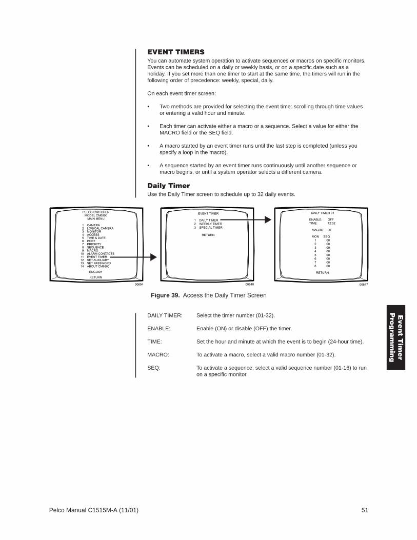
Pelco Manual C1515M-A (11/01) 51
EVENT TIMERSYou can automate system operation to activate sequences or macros on specific monitors.Events can be scheduled on a daily or weekly basis, or on a specific date such as aholiday. If you set more than one timer to start at the same time, the timers will run in thefollowing order of precedence: weekly, special, daily.
On each event timer screen:
• Two methods are provided for selecting the event time: scrolling through time valuesor entering a valid hour and minute.
• Each timer can activate either a macro or a sequence. Select a value for either theMACRO field or the SEQ field.
• A macro started by an event timer runs until the last step is completed (unless youspecify a loop in the macro).
• A sequence started by an event timer runs continuously until another sequence ormacro begins, or until a system operator selects a different camera.
Daily TimerUse the Daily Timer screen to schedule up to 32 daily events.
Figure 39. Access the Daily Timer Screen
DAILY TIMER: Select the timer number (01-32).
ENABLE: Enable (ON) or disable (OFF) the timer.
TIME: Set the hour and minute at which the event is to begin (24-hour time).
MACRO: To activate a macro, select a valid macro number (01-32).
SEQ: To activate a sequence, select a valid sequence number (01-16) to runon a specific monitor.
PELCO SWITCHERMODEL CM6800
MAIN MENU
1 CAMERA2 LOGICAL CAMERA3 MONITOR4 ACCESS5 TIME & DATE6 PORT7 PRIORITY8 SEQUENCE9 MACRO
10 ALARM CONTACTS11 EVENT TIMER12 SET AUXILIARY13 SET PASSWORD14 ABOUT CM6800
ENGLISH
RETURN
00654
DAILY TIMER 01
ENABLE: OFFTIME: 12:02
MACRO 00
MON SEQ1 002 003 004 005 006 007 008 00
RETURN
00647
EVENT TIMER
1 DAILY TIMER2 WEEKLY TIMER3 SPECIAL TIMER
RETURN
00648
Eve
nt T
ime
rP
rog
ram
min
g

52 Pelco Manual C1515M-A (11/01)
PELCO SWITCHERMODEL CM6800
MAIN MENU
1 CAMERA2 LOGICAL CAMERA3 MONITOR4 ACCESS5 TIME & DATE6 PORT7 PRIORITY8 SEQUENCE9 MACRO
10 ALARM CONTACTS11 EVENT TIMER12 SET AUXILIARY13 SET PASSWORD14 ABOUT CM6800
ENGLISH
RETURN
00654
Figure 41. Access the Special Timer Screen
SPECIAL TIMER: Select the timer number (01-32).
ENABLE: Enable (ON) or disable (OFF) the timer.
TIME: Set the hour and minute at which the event is to begin (24-hour time).
DATE: Select the date on which the event is to begin (DD-MMM-YY).
MACRO: To activate a macro, select a valid macro number (01-32).
SEQ: To activate a sequence, select a valid sequence number (01-16) to runon a specific monitor.
EVENT TIMER
1 DAILY TIMER2 WEEKLY TIMER3 SPECIAL TIMER
RETURN
00648
SPECIAL TIMER 32
ENABLE: OFF
TIME: 10:00 DATE: 25-DEC-01
MACRO 00
MON SEQ1 012 023 084 085 086 087 088 08
RETURN
00661
Figure 40. Access the Weekly Timer Screen
WEEKLY TIMER: Select the timer number (01-32).
ENABLE: Enable (ON) or disable (OFF) the timer.
TIME: Set the hour and minute at which the event is to begin (24-hour time).
MACRO: To activate a macro, in the column under the desired day of the week,select a valid macro number (01-32).
SEQ: To activate a sequence, in the column under the desired day of theweek, select a valid sequence number (01-16) to run on a specificmonitor.
Special TimerUse the Special Timer screen to schedule up to 32 events on a specific date(s).
PELCO SWITCHERMODEL CM6800
MAIN MENU
1 CAMERA2 LOGICAL CAMERA3 MONITOR4 ACCESS5 TIME & DATE6 PORT7 PRIORITY8 SEQUENCE9 MACRO
10 ALARM CONTACTS11 EVENT TIMER12 SET AUXILIARY13 SET PASSWORD14 ABOUT CM6800
ENGLISH
RETURN
00654
EVENT TIMER
1 DAILY TIMER2 WEEKLY TIMER3 SPECIAL TIMER
RETURN
00648
WEEKLY TIMER 01
ENABLE: OFFTIME: 09:02
SUN MON TUE WED THU FRI SAT
MAC MAC MAC MAC MAC MAC MAC24 01 01 01 01 01 24
MON SEQ SEQ SEQ SEQ SEQ SEQ SEQ1 00 00 00 00 00 00 002 00 00 00 00 00 00 003 00 00 00 00 00 00 004 00 00 00 00 00 00 005 00 00 00 00 00 00 006 00 00 00 00 00 00 167 00 00 00 00 00 00 008 00 00 00 00 00 00 00
RETURN
00664
Weekly TimerUse the Weekly Timer screen to schedule up to 32 weekly events.
Eve
nt
Tim
er
Pro
gra
mm
ing

Pelco Manual C1515M-A (11/01) 53
LOGICAL CAMERA NUMBERSA logical number is a user-selectable, variable number, and is always associated with anactual physical input. A physical input number represents an actual BNC input on the rearpanel of the CM6800 and is a fixed number. Within the programming screens and at theoperator level the logical number is the number used for reference.
Example of a logical numbering plan:
Physical input number Location in store Logical number
Cameras 1-5 First floor 11-15
Cameras 6-12 Second floor 21-27
Use the Logical Camera screen to assign new logical numbers as appropriate for yoursystem.
Figure 42. Access the Logical Camera Number Screen
PHY: The physical input number represents an actual BNC input on the rearpanel of the CM6800 and cannot be changed.
LOG: Assign a valid logical number (0001-9998) to each physical camerainput. A valid number is any number from 0001 to 9998 that has notalready been assigned to a physical camera input.
Example: In Figure 43, physical camera input 22 is assigned alogical number of 0501. To view this camera an operatorwill do the following:
1. Enter 501.2. Press the CAM key.
Using the new logical camera number:
If you change a logical camera number in the programming menus, you cannot control thecamera until you select the camera number from the keyboard:
1. Enter the new logical camera number.2. Press the CAM key.
The CM6800 automatically updates all other usages of the logical camera number, such asin sequences and macros.
PELCO SWITCHERMODEL CM6800
MAIN MENU
1 CAMERA2 LOGICAL CAMERA3 MONITOR4 ACCESS5 TIME & DATE6 PORT7 PRIORITY8 SEQUENCE9 MACRO
10 ALARM CONTACTS11 EVENT TIMER12 SET AUXILIARY13 SET PASSWORD14 ABOUT CM6800
ENGLISH
RETURN
00654
LOGICAL CAMERA NUMBER MENU
PHY LOG PHY LOG PHY LOG
01 0001 17 0402 33 003302 0002 18 0403 34 003403 0003 19 0404 35 003504 0004 20 0405 36 003605 0005 21 0500 37 003706 0006 22 0501 38 003807 0007 23 0502 39 003908 0008 24 0503 40 004009 0009 25 0504 41 004110 0201 26 0505 42 004211 0202 27 0601 43 004312 0203 28 0602 44 004413 0301 29 0603 45 004514 0302 30 0604 46 004615 0303 31 0605 47 004716 0401 32 0032 48 0048
RETURN
00652
Lo
gic
al C
am
era
Nu
mb
ers

54 Pelco Manual C1515M-A (11/01)
MACROSMacros simplify operator control by grouping multiple functions into a single command. Usethe Macros screen to program up to 32 system macros.
Figure 43. Access the Macro Screen
MACRO: Select the macro number you want to program (1-32).
STP: Each macro can include up to 72 steps. For each step select entries forthe following fields as necessary:
CMD: Select a command. In addition, enter a valid number in thespecified additional field(s); for example, if you selectPATT, enter a pattern number in the Command # field, acamera number in the Camera field, and a monitornumber in the Monitor field.
Refer to Table H in the Appendix for a description of eachcommand and the additional fields required for eachcommand.
##: If applicable, enter a valid number associated with thecommand selected.
CAM: If applicable, enter a logical camera number. To selectlogical numbers other than the default numbers (1 to 48),you must first program the logical numbering in theLogical Camera window. Refer to the Logical CameraNumbers section.
MON: If applicable, enter a monitor number.
DWL: If desired, enter a dwell time (1-99 seconds); the dwelltime is the period the macro halts before continuing to thenext step. The default dwell time is two seconds.
PELCO SWITCHERMODEL CM6800
MAIN MENU
1 CAMERA2 LOGICAL CAMERA3 MONITOR4 ACCESS5 TIME & DATE6 PORT7 PRIORITY8 SEQUENCE9 MACRO
10 ALARM CONTACTS11 EVENT TIMER12 SET AUXILIARY13 SET PASSWORD14 ABOUT CM6800
ENGLISH
RETURN
00654
MACRO MENU
MACRO 01 HELPSTP CMD ## CAM MON DWL01 SWT 000 0001 01 0102 SWT 000 0002 02 0203 SWT 000 0003 03 0304 SWT 000 0004 04 0405 PRES 001 0005 08 0106 — — — —000 0006 00 0107 — — — —000 0007 00 0108 — — — —000 0008 00 0109 — — — —000 0009 00 0110 — — — —000 0010 00 0111 — — — —000 0011 00 0112 — — — —000 0012 00 0113 — — — —000 0013 00 0114 — — — —000 0014 00 0115 — — — —000 0015 00 0116 — — — —000 0016 00 0117 — — — —000 0017 00 0118 — — — —000 0018 00 01
NEXT PREVIOUS
RETURN
00653
Ma
cro
s

Pelco Manual C1515M-A (11/01) 55
MACRO STATUS VIEW SCREENThe Macro Status View screen provides a status view of each system macro (1-32). Foreach active macro the current status (RUN or HOLD) and the number of the next macrostep is displayed. If a macro is not running, the status is IDLE and the step number is 00.
A system operator can display the Macro Status View screen without entering password-protected programming screens.
MACRO STATUSMAC
123456789
10111213141516
STATUSRUNIDLE
HOLDIDLERUNIDLEIDLEIDLEIDLEIDLEIDLEIDLEIDLEIDLEIDLEIDLE
STEP01092300000000000000000000000000
MAC17181920212223242526272829303132
STATUSHOLDRUNIDLEIDLEIDLEIDLEIDLEIDLEIDLEIDLEIDLEIDLEIDLEIDLEIDLEIDLE
STEP00220000000000000000000000000000
REFRESHEXIT
PELCO VIDEO SWITCHERMODEL CM6800
PASSWORD TO MAIN MENU*******
SCRATCHPAD SEQUENCE
RETURNMACRO STATUS VIEW
Figure 44. Macro Status View Screen
Ma
cro
s

56 Pelco Manual C1515M-A (11/01)
MONITOR DISPLAYUse the Monitor screen to adjust monitor display settings for your system. You can adjustsettings for the current monitor only (CURRENT) or for all system monitors (ALL).
Figure 45. Access the Monitor Screen
MONITOR: Select CURRENT to program the monitor display for the monitor youare currently operating or ALL for all monitors connected to the CM6800.
If you select ALL, you must navigate left or right in the SET ALL field toapply programming changes (refer to the SET ALL field description).
CAMERA NUMBER: Enable (ON) or disable (OFF) on-screen display of the logical cameranumber.
CAMERA TITLE: Enable (ON) or disable (OFF) on-screen display of the camera title(maximum of 20 alphanumeric characters).
R/X TYPE: Enable (ON) or disable (OFF) on-screen display of the cameracontrol type. The letter displayed on the monitor reflects the receivercontrol type selected in the CONTROL field on the Camera screen.
R/X TYPE DISPLAY VALUES:E = Coaxitron extended mode (32-bit)S = Coaxitron standard mode (15-bit)M = Genex multiplexerP = PTZ-P (RS-422 through Control Port PTZ-A or PTZ-B)D = PTZ-D (RS-422 through Control Port PTZ-A or PTZ-B)
PELCO SWITCHERMODEL CM6800
MAIN MENU
1 CAMERA2 LOGICAL CAMERA3 MONITOR4 ACCESS5 TIME & DATE6 PORT7 PRIORITY8 SEQUENCE9 MACRO
10 ALARM CONTACTS11 EVENT TIMER12 SET AUXILIARY13 SET PASSWORD14 ABOUT CM6800
ENGLISH
RETURN
00654
MONITOR CURRENT
CAMERA NUMBER: ONCAMERA TITLE: ONR/X TYPE: ONMON/ALM NUMBER: ONMON/ALM STATUS: ONTIME: ONDATE: ONBRIGHTNESS 8
POSITION DISPLAY
SET ALL
RETURN
00655
00620
00620
00620
Mo
nit
or
Pro
gra
mm
ing

Pelco Manual C1515M-A (11/01) 57
TEST POSITIONING MENUPRESS PGM EXIT
- - - - - -
00633
MON/ALM NUMBER: Enable (ON) or disable (OFF) on-screen display of the monitor/alarm number. During normal operation, the monitor numberappears in this field. The monitor number is a fixed number,representing an actual BNC output on the rear panel of the CM6800.When an alarm is active, the alarm number appears in this field. Thealarm number represents an alarm contact – the physical alarminput number of an internal alarm contact, or the address of anexternal alarm contact as configured on the Alarm Interface Unit.
MON/ALM STATUS: Enable (ON) or disable (OFF) on-screen display of the monitor oralarm status.
MONITOR STATUS DISPLAY VALUES:Blank = normal statusH = holdS = sequence
NOTE: If an operator presses the HOLD key while an alarmappears on the monitor, the H does not appear. The alarm icon andalarm status value blink to indicate the HOLD status.
ALM STATUS DISPLAY VALUES:I = internal alarmE = external alarmV = video loss alarm
TIME: Enable (ON) or disable (OFF) on-screen display of the time asprogrammed in the system.
DATE: Enable (ON) or disable (OFF) on-screen display of the date asprogrammed in the system.
BRIGHTNESS: Select the brightness level of the on-screen display (1-8; 8 = whitecharacters, 1 = black characters; 2-7 = shades of gray).
If you select CURRENT in the MONITOR field, you can see thebrightness level change as you scroll through the options.
If you select ALL in the MONITOR field, the changes do not takeeffect until you apply changes in the SET ALL field.
POSITION DISPLAY: Navigate left or right to select the Test Positioning Menu.
The real-time camera display appears with Test Positioning Menutext superimposed on the screen. Use the position keys or joystickto move the text to the desired position on the screen. The textmoves one line or character position at a time.
Press the PGM key to exit the test positioning menu.
SET ALL: To apply monitor display changes to all system monitors (if youselected ALL in the MONITOR field) you must navigate left or right inthe SET ALL field; otherwise monitor display settings are notchanged.
If you selected CURRENT in the MONITOR field, navigating left orright in the SET ALL field has no effect.
00620
00620
0001 E CAM 10001 V 01-JAN-01 01:01:01
V
00634
00620
Mo
nito
rP
rog
ram
min
g

58 Pelco Manual C1515M-A (11/01)
PASSWORDUse the Set Password screen to change the system password.
If you change the password and then forget the new one, you will have to reset the systemto the factory defaults. All system programming will be lost. Pelco recommends uploadingyour programming settings to the CM6800-MGR before changing the password. This allowsyou to download the previous system settings, in the event of a system reset. If necessary,refer to the Troubleshooting section for the system reset procedure.
Figure 46. Access the Set Password Screen
OLD PASSWORD: Enter the current password (Default: 2899100). If you make a mistakeentering the old password, the message “WRONG OLD PASSWORD.TRY AGAIN!” appears. Re-enter the old password correctly.
NEW PASSWORD: Using the numerical keypad, enter the new password. The passwordmust be seven digits.
VER PASSWORD: Enter the new password again as a verification check. If you make amistake entering the verification password, the message “VERIFIEDPASSWORD DOESN’T MATCH” appears. Re-enter the verificationpassword correctly.
Once the new password is accepted, the Main Menu appears.
PELCO SWITCHERMODEL CM6800
MAIN MENU
1 CAMERA2 LOGICAL CAMERA3 MONITOR4 ACCESS5 TIME & DATE6 PORT7 PRIORITY8 SEQUENCE9 MACRO
10 ALARM CONTACTS11 EVENT TIMER12 SET AUXILIARY13 SET PASSWORD14 ABOUT CM6800
ENGLISH
RETURN
00654
SET PASSWORD
OLD PASSWORD: *******NEW PASSWORD: *******VER PASSWORD: *******
RETURN
00656
Pa
ssw
ord
Pro
gra
mm
ing

Pelco Manual C1515M-A (11/01) 59
Figure 47. Access the Port Screen
SET SERIAL PORT: Select the number of the desired Serial Port/COM port (01-10).
The serial port numbers correspond to the communication ports onthe CM6800 rear panel as follows:
Serial Port Input on CM6800 rear panel
01 COM 1
NOTE: COM 1 can be accessed through a DB9input or an RJ-45 port.
02-08 COM 2-8 RJ-45 inputs
09 PTZ-A control input
10 PTZ-B control input
DEVICE: Select the device connected to the COM port; the values in theTYPE, BAUD RATE, PARITY, DATA BITS, and STOP BITS fieldschange to the settings appropriate for the specific device.
TYPE: If necessary, and if allowed, select the desired communication type(RS-232, RS-422, or RS-485).
BAUD RATE: Select the desired baud rate.
PARITY: Select the desired parity type.
DATA BITS: This value cannot be changed.
STOP BITS: This value cannot be changed.
PELCO SWITCHERMODEL CM6800
MAIN MENU
1 CAMERA2 LOGICAL CAMERA3 MONITOR4 ACCESS5 TIME & DATE6 PORT7 PRIORITY8 SEQUENCE9 MACRO
10 ALARM CONTACTS11 EVENT TIMER12 SET AUXILIARY13 SET PASSWORD14 ABOUT CM6800
ENGLISH
RETURN
00654
SET SERIAL PORT 05
DEVICE: KBD300TYPE: RS485BAUD RATE: 9600PARITY: ODDDATA BITS: 8STOP BITS: 1
RETURN
00657
NOTE: In the programmingscreens “KBD300” is usedto refer to the KBD100,KBD200, and KBD300keyboards.
PORTS (SERIAL/COM PORTS)Use the Port screen to configure the settings for each device connected to a Serial/COMport on the rear panel of the CM6800.
Po
rtP
rog
ram
min
g

60 Pelco Manual C1515M-A (11/01)
PRIORITY CONTROLThe CM6800 provides eight levels of priority control. Each level defines the ability of akeyboard to control a pan/tilt/zoom (camera positioning system) and to access program-ming screens.
Priority level applies system wide; a keyboard assigned priority level 2 on COM port 8 has ahigher priority than a keyboard assigned priority level 4 on COM port 5. A higher levelkeyboard takes precedence over a lower level keyboard when the keyboards are issuingcontrol commands.
NOTE: You can connectonly one ASCII keyboard/de-vice per port on the CM6800(COM port 1, 2, 4, 7, or 8).For ASCII keyboards prioritycontrol is based on the entryfor keyboard 1.
Figure 48. Access the Priority Screen
PORT: Select the COM port number for which you are programming prioritycontrol.
PRIORITY: For each keyboard connected to the specified port, assign a priority level(01-08).
OPTIONS:Level 1 = highest priorityLevel 8 = lowest priority
Levels 1 - 4 have the ability to access programming screens. Levels5-8 cannot access programming screens. The lowest level orkeyboards located at the same level will access devices on first-come,first-served basis.
PELCO SWITCHERMODEL CM6800
MAIN MENU
1 CAMERA2 LOGICAL CAMERA3 MONITOR4 ACCESS5 TIME & DATE6 PORT7 PRIORITY8 SEQUENCE9 MACRO
10 ALARM CONTACTS11 EVENT TIMER12 SET AUXILIARY13 SET PASSWORD14 ABOUT CM6800
ENGLISH
RETURN
00654
KEYBOARD PRIORITY MENU
PORT 05
KBD PRIORITY1 012 023 084 085 086 087 088 08
RETURN
00658
Pri
ori
tyP
rog
ram
min
g

Pelco Manual C1515M-A (11/01) 61
SEQUENCESThe CM6800 provides two types of sequences:
• An operator can program a scratchpad sequence from an individual monitor, withoutaccessing password-protected programming screens.
• System sequences are password-protected and can run on any system monitor.
Figure 49. Access the Sequence Screen
Figure 50. Access the Scratchpad Sequence Screen
SEQUENCE: Select the sequence number you want to program (1-16).
STP: Each sequence can include up to 72 steps. For each step selectentries for the following fields as necessary:
CAM: Enter the desired camera number (logical number).
DWL: Enter the dwell time (01-99 seconds).
CMD and ##: Select a command; if you select a pattern or apreset enter a valid pattern or preset number.
OPTIONS:PRES = presetPATT = patternRSCN = random scanFSCN = frame scanSSCN = stop scan
AUX and ##: Select an auxiliary to be activated.Global = internal and external auxiliaries.
OPTIONS:GON = turn global auxiliary on (1-128)GOFF = turn global auxiliary off (1-128)CON = turn camera auxiliary on (1-8)COFF = turn camera auxiliary off (1-8)
PELCO SWITCHERMODEL CM6800
MAIN MENU
1 CAMERA2 LOGICAL CAMERA3 MONITOR4 ACCESS5 TIME & DATE6 PORT7 PRIORITY8 SEQUENCE9 MACRO
10 ALARM CONTACTS11 EVENT TIMER12 SET AUXILIARY13 SET PASSWORD14 ABOUT CM6800
ENGLISH
RETURN
00654
SEQUENCE 01 HELP
STP CAM DWL CMD ## AUX ##01 0001 02 PATT 01 CON 00002 0002 02 PRES 01 CON 00003 0003 03 SSCN 00 — — — — 00004 0004 02 FSCN 00 — — — — 00005 0005 08 PRES 04 COFF 00006 0006 02 — — — — 00 — — — — 00007 0006 02 — — — — 00 — — — — 00008 0006 02 — — — — 00 — — — — 00009 0006 02 — — — — 00 — — — — 00010 0006 02 — — — — 00 — — — — 00011 0006 02 — — — — 00 — — — — 00012 0006 02 — — — — 00 — — — — 00013 0006 02 — — — — 00 — — — — 00014 0006 02 — — — — 00 — — — — 00015 0006 02 — — — — 00 — — — — 00016 0006 02 — — — — 00 — — — — 00017 0006 02 — — — — 00 — — — — 00018 0006 02 — — — — 00 — — — — 000
NEXT PREVIOUS
RETURN
00660
SCRATCHPAD SEQUENCE MON ##
STP CAM DWL CMD ## AUX ##01 0001 02 PATT 02 CON 00102 0005 02 PRES 12 GOFF 10103 0008 02 FSCN 00 CON 00804 0012 02 RSCN 00 — — — —00005 0023 02 SSCN 00 — — — —00006 0006 02 — — — — 00 — — — —00007 0007 02 — — — — 00 — — — —00008 0008 02 — — — — 00 — — — —00009 0009 02 — — — — 00 — — — —00010 0010 02 — — — — 00 — — — —00011 0011 02 — — — — 00 — — — —00012 0012 02 — — — — 00 — — — —00013 0013 02 — — — — 00 — — — —00014 0014 02 — — — — 00 — — — —00015 0015 02 — — — — 00 — — — —00016 0016 02 — — — — 00 — — — —00017 0017 02 — — — — 00 — — — —00018 0018 02 — — — — 00 — — — —000
HELP
NEXT PREVIOUS
RETURN
00659
PELCO VIDEO SWITCHERMODEL CM6800
PASSWORD TO MAIN MENU*******
SCRATCHPAD SEQUENCE
RETURN
00619
NOTE: The auxiliaries onthe rear panel of theCM6800 are activated byglobal auxiliary numbers 1,2, and 3.
Se
qu
en
ce
Pro
gra
mm
ing

62 Pelco Manual C1515M-A (11/01)
TIME AND DATEUse the Time and Date screen to set the system time and date settings. The time and datedisplayed on the monitor during real-time camera display is the time set in the memorythrough this screen. The system time and date information is kept current in battery-backedRAM. New time and date information will be set when you apply the changes (refer to theSET TIME & DATE field description).
Figure 51. Access the Time and Date Screen
DATE: Select or enter the month, day, and year of the desired system date.
TIME: Select or enter the hour, minute, and second of the desired systemtime.
FORMAT: Select the on-screen date format.
OPTIONS:DD/MMM/YYMMM/DD/YYYY/MMM/DDDD/MM/YYMM/DD/YYYY/MM/DD
STYLE: Select the on-screen time format. This setting affects the on-screentime displayed on system monitors only. System functions pro-grammed through the event timers (refer to Event Timers in thissection) are based on 24-hour time settings.
OPTIONS:24HrAM/PM (12 Hr)
SET TIME & DATE: You must navigate left or right in the SET TIME & DATE field toapply the changes.
PATTERNS, PRESETS, AND ZONESSpecial characters added through the CM6800-MGR may not be available with yourcamera positioning system. Preset, pattern, and zone labels containing special characterswill appear on the monitor with blanks in place of the special characters.
Refer to the Operation section for instructions on creating patterns. Refer to your keyboardmanual for instructions on programming presets and zones.
PELCO SWITCHERMODEL CM6800
MAIN MENU
1 CAMERA2 LOGICAL CAMERA3 MONITOR4 ACCESS5 TIME & DATE6 PORT7 PRIORITY8 SEQUENCE9 MACRO
10 ALARM CONTACTS11 EVENT TIMER12 SET AUXILIARY13 SET PASSWORD14 ABOUT CM6800
ENGLISH
RETURN
00654
SET TIME & DATE
SETMM DD YY
DATE: 01 / 01 / 01TIME: 01 : 01 : 01
DISPLAY AS
FORMAT: DD/MMM/YYSTYLE: 24Hr
SET TIME & DATE
RETURN
00662
Tim
e a
nd
Da
teP
rog
ram
min
g

Pelco Manual C1515M-A (11/01) 63
OPERATION
OVERVIEW
A brief description of CM6800 operation is provided here. Refer to the following sections fordetailed instructions and options.
Install the CM6800 andconnect all system devices.
Power-up the system.
Switch monitor.
Select camera.
Control PTZ receivers.
Call a preset.
System does not function.
Refer to the Installation section.
Refer to the System Start-up section.
1. Enter the monitor number.2. Press the MON key.
1. Enter the camera number.2. Press the CAM key.
Use the appropriate PTZ control keys or joystick(depending on the keyboard used).
Extended Coaxitron protocol receivers can be operatedwithout any programming changes. Other receivercontrol protocols require programming changes.
Program the preset through the keyboard.1. Enter the preset number.2. Press the PRESET key or Prst/Lock key
(depending on the keyboard used).
Refer to the Troubleshooting section.
OPERATING THE CM6800
The CM6800 can be operated with a KBD100, KBD200, KBD300, KBD960, or KBR960keyboard. Operation instructions are provided below, but you should become familiar withthe detailed instructions provided in the appropriate keyboard manual.
The CM6800 can also be controlled with ASCII commands. Refer to the ASCII OperatingCommands section.
SWITCH MONITORSIf you select a restricted monitor, the monitor does not switch; the keyboard LED displaysthe previously selected monitor number.
ALL KEYBOARDS
1. Enter the monitor number.2. Press the MON key. The keyboard LED displays the selected monitor number.
Op
era
tion

64 Pelco Manual C1515M-A (11/01)
SELECT CAMERASIf you select a restricted camera view, the camera view does not appear on that monitor.The previously selected, unrestricted camera view remains on the monitor.
KBD960/KBR960 KEYBOARDS
1. Enter the camera number.
2. Press the CAM key.
OR
Press the BWD or FWD key to scroll
through the available cameras.
OR
From the Camera Menu, select
or to scroll through the available
cameras.
KBD100/200/300 KEYBOARDS
1. Enter the camera number.2. Press the CAM key.
OR
Press the PREV or NEXT key to scrollthrough the available cameras.
CONTROL RECEIVERSSelect a suitable camera and operate a PTZ function. A keyboard with “view-only” accesscan view the signal from the specified camera but cannot control the camera.
Extended Coaxitron protocol receivers can be operated without any programming changes.Other receiver control protocols require programming changes. Refer to the Programmingsection.
Receiver control is not available with the KBD100 keyboard.
KBD200 KEYBOARD
Pan/Tilt/Zoom
Press and hold the appropriate pan/tilt key untilthe camera reaches the desired position. Tochange the speed of movement, press a number(1-9) key first (1=slowest, 9=fastest).
Press and hold the appropriate zoom key untilthe desired effect is seen. To change the speedof zoom, press a number (1-4) key and thenpress the WIDE key (1=slowest, 4=fastest).
Lens Control: Focus, Iris
Press and hold the appropriatelens control key until the desiredeffect is seen. To change thespeed of focus, press a number(1-4) key, and then press theFAR key (1=slowest, 4=fastest).
KBD300 KEYBOARD
Pan/Tilt/Zoom
Move the joystick until the camera reaches thedesired position. To increase the speed ofmovement, move the joystick farther from center.
Twist the joystick clockwise to zoom in,counterclockwise to zoom out. To change thespeed of zoom, press a number (1-4) key andthen twist the joystick (1=slowest, 4=fastest).
Lens Control: Focus, Iris
Press and hold the appropriatelens control key until the desiredeffect is seen. To change thespeed of focus, press a number(1-4) key, and then press theFAR key (1=slowest, 4=fastest).
Op
era
tio
n

Pelco Manual C1515M-A (11/01) 65
OPERATE SEQUENCESYou can run a scratchpad sequence from an individual monitor or a system sequence onany monitor accessible from the keyboard. When running a sequence, any cameras notaccessible to the keyboard will be bypassed.
KBD100/200/300 KEYBOARDS
Run a Sequence
1. Enter a sequence number (1-16). Skipthis step to run a scratchpad sequence.
2. Press and hold the NEXT or PREV keyto move forward or backward throughthe sequence.To move through the sequence onecamera at a time:Press the NEXT key to move forward.Press the PREV key to move backward.
Pause a Sequence
1. Press the HOLD key; monitor displays H.2. Press the HOLD key to resume.
Stop a Sequence
1. Enter a camera number.2. Press the CAM key.
KBD960/KBR960 KEYBOARDS
Run a Sequence
1. Select .
2. Enter a sequence number (1-16for a system sequence; 0 for thescratchpad sequence).
3. Select to start the sequence.
OR
1. Select .
2. Select to enter the SequenceMenu.
3. Enter a sequence number (1-16).OR
Select or to scrollthrough available sequences.
4. Select or to start the
sequence.
NOTE: You can define a function keyto run a sequence. Refer to theKBD960 Keyboard Installation/Operation Manual for instructions.
Pause a Sequence
1. Select .
2. Select or to resume.
Stop a Sequence
1. Select .
OR1. Enter a camera number.2. Press the CAM key.
SEQ
SEQ
KBD960/KBR960 KEYBOARDS
Lens Control: Focus, Iris
Use the NEAR/FAR key to focusnear or far.
Use the OPEN/CLS key to openor close the iris.
Pan/Tilt/Zoom
Move the joystick until the camera reaches thedesired position. To increase the speed ofmovement, move the joystick farther fromcenter or press the T key to pan at turbo speed.
Twist the joystick clockwise to zoom in,counterclockwise to zoom out. Or use the IN/OUT key to zoom in or out.
Op
era
tion

66 Pelco Manual C1515M-A (11/01)
RUN A MACRO
KBD100/200/300 KEYBOARDS
Run a Macro
1. Enter the macro number.2. Press the MACRO key.
Stop a Macro
1. Enter the number of the runningmacro.
2. Press the MACRO key.
KBD960/KBR960 KEYBOARDS
Run a Macro
1. Select .
2. Enter a macro number.
3. Select to start the macro.
OR
1. Select .
2. Select to enter the Macro
Menu.
3. Enter a macro number.
OR
Select or to scroll
through available macros.
4. Select or to start themacro.
NOTE: You can define a function keyto run a macro. Refer to the KBD960Keyboard Installation/OperationManual for instructions.
Pause a Macro
1. Select .
2. Select or to resume.
Stop a Macro
1. Select .
OR1. Enter a camera number.2. Press the CAM key.
MAC
MAC
Op
era
tio
n

Pelco Manual C1515M-A (11/01) 67
ACKNOWLEDGE AN ALARMWhen an alarm is triggered, an alarm icon appears on the monitors programmed to showthat alarm.
KBD960/KBR960 KEYBOARDS
1. Select .
2. Select to reset the alarm on
the individual monitor.
OR
Select to reset the alarm on
all monitors.
You can also select to mute the
alarm.
NOTE: You can define a function keyto acknowledge an alarm. Refer tothe KBD960 Keyboard Installation/Operation Manual for instructions.
KBD100/200/300 KEYBOARDS
1. Enter the monitor number.2. Press the MON key.3. Press the ACK key. The alarm is
removed from the selected monitor.4. Repeat for each alarm.
KBD200/300 KEYBOARDS
1. Enter the preset number.2. Press the PRESET key.
KBD960/KBR960 KEYBOARDS
1. Enter the preset number.2. Press the Prst/Lock key.
ORSelect the PRST icon.
CALL A PRESETProgram the preset through the keyboard. Refer to the appropriate keyboard manual forinstructions. Presets are not available with the KBD100 keyboard.
Op
era
tion

68 Pelco Manual C1515M-A (11/01)
CREATE AND RUN A PATTERNPatterns are not available with the KBD100 keyboard.
OPERATE AUXILIARIES/RELAYSLocal auxiliaries are the outputs on the rear panel of the CM6800. External auxiliaries areavailable by connecting an REL2064 Relay Interface Unit to the CM6800 through COM port 3.
Operate a Local Auxiliary
KBD960/KBR960 KEYBOARDS
Refer to the KBD960 KeyboardInstallation/Operation manual forinstructions on creating a pattern.
1. Select to display the Preset
Menu.
2. Select to start a pattern.
OR
1. Select to display the Preset
Menu.
2. Enter 1.
3. Select to run the first pattern
of previously defined half-patterns.
OR
1. Select to display the Preset
Menu.
2. Enter 2.
3. Select to run the second
pattern of previously defined
half-patterns.
PRST
PRST
PRST
KBD200/300 KEYBOARDS
Create a Long Pattern
1. Enter a camera number.2. Enter 1.3. Press and hold the PATTERN key for
two seconds.4. The monitor will indicate the program-
ming function is active. Move the cameraposition as desired for the pattern.
5. Press the ACK key to close theprogramming function.
Create a Shart Pattern
1. Enter a camera number.2. Enter the short pattern number (2 or 3).3. Press and hold the PATTERN key for
two seconds.4. The monitor will indicate the program-
ming function is active. Move the cameraposition as desired for the pattern.
5. Press the ACK key to close theprogramming function.
Run a Long Pattern
1. Enter 1.2. Press the PATTERN key.3. Move the joystick or call a preset to
stop the pattern.
Run a Short Pattern
1. Enter the short pattern number (2 or 3).2. Press the PATTERN key.3. Move the joystick or call a preset to
stop the pattern.
KBD100/200/300 KEYBOARDS
Auxiliary 1 relay: Press F1 to activate/deactivate.
Auxiliary 2 TTL output: Press F2 toactivate/deactivate.
KBD960/KBR960 KEYBOARDS
Auxiliary 1 relay: Press F12* toactivate/deactivate.
Auxiliary 2 TTL output: Press F24* toactivate/deactivate.
* F12 and F24 are the default auxiliarycontrol function keys; user-selectedfunction keys can be defined through theKey Define Menu. Refer to the KBD960Keyboard Installation/Operation Manualfor instructions.
NOTE: If you connect REL2064 RelayInterface Units (up to two) to theCM6800, operation of the two relays onthe rear panel of the CM6800-32X6 willalso operate the first two relays on thefirst external unit (unless you numberthe external relays starting at 64).
Op
era
tio
n

Pelco Manual C1515M-A (11/01) 69
Operate an External AuxiliaryThe CM6800 can control up to two REL2064 Relay Interface Units connected to thesystem. Each unit provides 64 relays. Refer to the REL2064 Relay Interface UnitInstallation/Operation Manual for detailed information. External relays cannot be operatedwith the KBD100.
KBD960/KBR960 KEYBOARDS
1. Enter the GPI number for the
appropriate relay output.
2. Press .
3. Press the desired AUX number
icon to activate the relay and
associated peripheral device.
(Press to access AUX 5-8.)
4. If is highlighted, the operation
is momentary. If is not
highlighted, the operation is
latching. Refer to the KBD960
Keyboard Installation/Operation
Manual for instructions.
KBD200/300 KEYBOARD
The KBD200/300 keyboards (firmwareversion 4.2 and later) can operate externalrelays.
Refer to the KBD200 Keyboard Installation/Operation Manual or the KBD300Keyboard Installation/Operation Manual forinstructions.
NOTE: External relays cannot be operatedwith KBD200/300 keyboard firmwareversions prior to 4.2.
Operate an Auxiliary in a ReceiverAuxiliary control is not available with the KBD100.
KBD960/KBR960 KEYBOARDS
From the Camera Menu, press ,
and then release to control an AUX 1
momentary function on the selected
camera.
Press to control an AUX 2
momentary function. Press to
access through .
KBD200/300 KEYBOARDS
Press F4 to activate.
Press F5 to deactivate.
ORTo control a momentary function:
1. Enter the auxiliary number.
2. Press and hold F4, and then release.
GPI
MTRY
MTRY
1
2
3 8
Op
era
tion

70 Pelco Manual C1515M-A (11/01)
OPERATE SCANNING FUNCTIONSOperation of the scanning functions depends on the kind of receiver or pan/tilt mechanismyou have. Refer to the appropriate keyboard manual for detailed instructions on operatingscanning functions.
DETECT VIDEO LOSSThe CM6800 detects video loss from any system camera. If video is lost from a camera,the CM6800 blue screen appears on any monitor viewing that camera. When video isrestored to that camera, the camera view appears on the monitor(s) again. If the system isprogrammed for a video loss alarm, the alarm icon appears.
DEFINE ZONESA zone is a user-defined, physical location to which (1) a label is attached and (2) a camerais associated. When the associated camera is panned through or remains within thisdefined zone the zone label appears on the monitor.
Refer to the appropriate keyboard manual for detailed instructions on defining zones.
KBD200/300 KEYBOARDS
1. Enter the number of the multiplexerinput.
2. Press the CAM key.
3. Press the SHIFT key. When theSHIFT LED is lit, the keyboard can beused to operate the following Genexmultiplexer function keys:
F1: Digital zoomF2: PIP displayF3: Quad displayF4: 9-screen displayF5: 16-screen display
To select a camera through themultiplexer:
a. Enter the desired camera number(1-16, based on the cameraassignments set through themultiplexer).
b. Press the CAM key.
4. Press the SHIFT key to return tonormal keyboard operation.
When the SHIFT LED is off, you cancontrol the currently selected PTZcamera through the multiplexer.
To return to camera selectioncontrolled by the CM6800:
a. Select the desired camera number.b. Press the CAM key.c. Move the joystick as necessary.
CONTROL GENEX MULTIPLEXER AND GENEX MULTIPLEXERDISPLAYSMultiplexer control is not available with the KBD100.
KBD960/KBR960 KEYBOARDS
1. Press to access the MUX
Control Menu.
2. Press or to scroll through
the available MUX camera numbers.
3. Press if necessary. must
be highlighted before the system
can control Genex Multiplexer
functions.
4. Move the joystick or press the
appropriate MUX control icons as
necessary for multiplexer opera-
tion. Refer to the KBD960
Keyboard Installation/Operation
Manual for detailed operation
instructions.
MUX MUX
MUX
Op
era
tio
n

Pelco Manual C1515M-A (11/01) 71
APPENDIX
CM6800 DIP SWITCHES
00621
Figure 52. CM6800 DIP Switches – Factory Default Settings
Table G. CM6800 DIP Switch Settings
CM6800 DIP Switch Factory Default
SW1 OFF (0) = NTSC CM6800-48X8: OFFON (1) = PAL CM6800-48X8-X: ON
SW2 RESERVED – must be in the OFF position for OFFproper operation
SW3 RESERVED – must be in the OFF position for OFFproper operation
SW4 RESERVED – must be in the ON position for ONproper operation
SW5 RESERVED – must be in the OFF position for OFFproper operation
SW6 RESERVED – must be in the OFF position for OFFproper operation
SW7 SOFTWARE RESET TO FACTORY DEFAULTS OFFCAUTION: Resetting the software restoresthe system to default settings. All userprogramming is lost.
SW8 RESERVED – must be in the OFF position for OFFproper operation
Ap
pe
nd
ix

72 Pelco Manual C1515M-A (11/01)
MACRO COMMANDS
Table H provides a description of each macro command and the additional fields requiredfor each command. Refer to the Macro section for instructions on programming macros.
Table H. Macro Commands
Command Description Specify Field(s)
GON Activate an auxiliary. Auxiliary (1-128) Command #
GOFF Turn off an auxiliary. Auxiliary (1-128) Command #
Auxiliary Notes:• “Global” includes both internal and external auxiliaries.• Auxiliaries on the rear panel of the CM6800-32X6 Matrix Switcher are activated by global auxiliary numbers 1, 2 and 3.
CON Activate a camera auxiliary. Camera auxiliary (1-8) Command #
Camera (1-48) Camera
Monitor (1-8) Monitor
COFF Turn off a camera auxiliary. Camera auxiliary (1-8) Command #
Camera (1-48) Camera
Monitor (1-8) Monitor
SEQ Start a sequence. Sequence (1-16) Command #
Monitor (1-8) Monitor
SWT Switch a camera to a monitor. Camera (1-48) Camera
Monitor (1-8) Monitor
COPY Copy a camera view to a monitor. Monitor (1-8) to copy from Command #
Monitor (1-8) to copy to Monitor
GO TO Go to step number specified. Step (1-72) Command #
LOOP Loop a macro. 0 = loop continuously Command #1-999 = loop the specifiednumber of times
MACR Start a specific macro. Macro (1-32) Command #
?AUX Check a local auxiliary; if the auxiliary is active, the Local auxiliary (1-3) Command #next step is executed; if the auxiliary is not active,the next step is skipped.
END Exit the macro; no further steps are executed. None None
MSWT Switch a camera connected through the multiplexer. Camera to switch (1-16)� Command #
Multiplexer input (1-48) Camera
Monitor (1-8) Monitor
PIPB Display multiplexer picture-in-picture view with the Background camera (1-16)� Command #designated camera in the background. Multiplexer input (1-48) Camera
Monitor (1-8) Monitor
PIPF Display multiplexer picture-in-picture view with the Foreground camera (1-16)� Command #designated camera in the foreground. Multiplexer input (1-48) Camera
Monitor (1-8) Monitor
� For multiplexer functions, the camera number is the number of the video input on the multiplexer.The multiplexer input number is the number of the video input on the rear panel of the CM6800.
(Continued on next page)
Ap
pe
nd
ix

Pelco Manual C1515M-A (11/01) 73
Table H. Macro Commands (Continued)
Command Description Specify Field(s)
PIPO Turn off multiplexer picture-in-picture view. Multiplexer input (1-48) Camera
Monitor (1-8) Monitor
QUAD Display multiplexer four-camera mode. Camera group (1-4)* Command #
Multiplexer input (1-48) Camera
Monitor (1-8) Monitor
NANO Display multiplexer nine-camera mode. Camera group (1-3)* Command #
Multiplexer input (1-48) Camera
Monitor (1-8) Monitor
HEX Display multiplexer sixteen-camera mode. Multiplexer input (1-48) Camera
Monitor (1-8) Monitor
ZOOM Zoom multiplexer camera view. 1 = zoom once Command #
2 = zoom twice
Multiplexer input (1-48) Camera
Monitor (1-8) Monitor
AAI Arm internal alarm. Internal alarm (1-8) Command #
DAI Disarm internal alarm. Internal alarm (1-8) Command #
AAE Arm external alarm. External alarm (1-128) Command #
DAE Disarm external alarm. External alarm (1-128) Command #
AAV Arm video loss detection for a camera. Physical camera number (1-32) Command #
OR
Logical camera number Camera
DAV Disarm video loss detection for a camera. Physical camera number (1-32) Command #
OR
Logical camera number Camera
PATT Start a pattern. Pattern (#)** Command #
Camera (1-48) Camera
Monitor (1-8) Monitor
PRES Start a preset. Preset (#)** Command #
Camera (1-48) Camera
Monitor (1-8) Monitor
RSCN Start a random scan. Camera (1-48) Camera
Monitor (1-8) Monitor
FSCN Start a frame scan. Camera (1-48) Camera
Monitor (1-8) Monitor
SSCN Stop a scan. Camera (1-48) Camera
Monitor (1-8) Monitor
* Refer to the MX4000 Genex Series Simplex and Duplex Multiplexers Installation/Operation Manual for information on multiplecamera displays.
** The number of patterns and presets available is determined by the camera positioning system. Refer to the appropriate camerapositioning system manual.
Ap
pe
nd
ix

74 Pelco Manual C1515M-A (11/01)
ASCII OPERATING COMMANDS
ASCII protocol uses the ASCII character set to transmit and receive commands between apersonal computer (PC) and the CM6800. The commands are readable but are not English.
ASCII commands control the pan and tilt mechanisms (fixed and variable speed), camerafunctions, auxiliary relays, and alarms.
The ASCII protocol communicates in a standard asynchronous, byte-oriented protocol thatincludes: 1 start bit, 8 data bits, 1 parity bit (odd parity), and 1 stop bit. The defaultcommunication rate is 9600 baud.
A lowercase “a” ends each command. The ASCII translator acknowledges acceptedcommands and rejected commands with the following responses:
AKa command acceptedNAa command rejected or the ASCII translator does not recognize the command
If the command requires a numeric value, enter the number first.
Table I provides examples of ASCII commands. Table J lists all of the commands.
Table I. Examples of ASCII Commands
Functional Procedure Commands Result
Select a pan and tilt 3Ma16#a Switch camera 16 to currently selecteddevice labeled monitor 3.“CAMERA # 16” andswitch it to monitor # 3.
Manipulate the pan 1Ma3#a Switch camera 3 to monitor 1.and tilt device. 5Ma2#a3\a Go to camera 2, preset 3, on monitor 5.
47Ra33Da Pan right at speed 47, tilt down at speed 33.
sa Stop all image motion.
Switch a camera. 1Ma3#a Switch camera 3 to monitor 1.
Call a preset. 5Ma2#a3\a Go to camera 2, preset 3, on monitor 5.
Pan and tilt. 47Ra33Da Pan right at speed 47, tilt down at speed 33.
Ap
pe
nd
ix

Pelco Manual C1515M-A (11/01) 75
Desired Action
Select monitor
Select cameraNext cameraPrevious camera
Start a sequence forward
Start a sequence backward
Hold a sequence
Hold a macro
Pan leftPan rightStop pan leftStop pan right
Tilt upTilt downStop tilt upStop tilt down
Zoom telephotoZoom wideStop zoom telephotoStop zoom wide
Focus nearFocus farStop focus nearStop focus far
Iris openIris closeStop iris openStop iris close
Stop all PTZ motion
Record patternExecute patternEnd pattern
Go to preset position
Set preset with a label
Set preset without a label
Begin zone
Begin zone with a label
End zone
Begin random scanBegin frame scanStop scan
Command
[1-9999]Ma
[1-9999]#a+a-a
[1-99]qa
[1-99]ba
ea
[1-32]ea
[1-64]La[1-64]Ra~La~Ra
[1-63]Ua[1-63]Da~Ua~Da
TaWa~Ta~Wa
NaFa~Na~Fa
OaCa~Oa~Ca
sa
[1-99]/a[1-99]pa[1-99]na
[1-99]\a
la[string]!a[1-9999]^a
[1-9999]-^a
[1-8](
la[string]!a[1-8](
[1-8])
1@2@~@
Result
Calls a monitor to use for camera operation.
Selects a camera to display on the current operating monitor. TheNEXT key (+) and PREV key (-) commands switch to the nextnumbered camera in the system.
Starts the selected sequence going forward (incrementing cameranumbers).
Starts the selected sequence going backward (decrementing cameranumbers).
Places the running sequence on hold, freezing the currently selectedcamera on the monitor. It lets you control the camera or switch. Thesequence is still “armed” on the monitor, but inactive.
Places the running macro on hold.
Moves the currently selected pan and tilt device left or right at the speedindicated. If you omit the speed, some devices move at their defaultspeed and others move at their slowest possible speed. Speedinformation has no effect on fixed speed devices.
Moves the currently selected pan and tilt device up or down at thespeed indicated. If you omit the speed, some devices move at theirdefault speed and others move at their slowest possible speed. Speedinformation has no effect on fixed speed devices.
Makes the currently selected camera zoom in (close up view) or zoomout (wide view).
Changes the good focus range nearer or farther on the currentlyselected camera.
Opens (brighter image) or closes (darker image) the iris on thecurrently selected camera.
Stops all image motion (stops pan, tilt, zoom, focus, and iris). Does notstop a pattern.
On receivers that do patterns, these commands let you record yourmotions and operations (for a limited time) and then have the systemrepeat them.
Recalls a stored preset position.
Sets a preset location with an embedded label, where the ASCII stringmust be UPPERCASE characters.
The [string] is an alphanumeric label up to 20 characters long and[1-9999] is the associated preset number.
NOTE: All transmitted characters must be ASCII.
Sets a preset location without an embedded label.
Begins a zone without a label.
Begins a zone with an embedded label. The ASCII string must beuppercase characters.
Ends the zone program
These commands start and stop scans.
Table J. ASCII Commands
Number ranges are enclosed in brackets – do not enter the brackets. When you control a fixed speed pan and tilt, omit the speedinformation.
(Continued on next page)
Ap
pe
nd
ix

76 Pelco Manual C1515M-A (11/01)
Desired Action
Auxiliary onAuxiliary off
Camera auxiliary onCamera auxiliary off
Start macro
Stop macro
Acknowledge alarm
Arm internal alarmArm external alarmArm video loss alarmDisarm internal alarmDisarm external alarmDisarm video loss alarm
Send camera title
Version
Set date and time
Command
[1-128]xa[1-128]~xa
[1-8]Aa[1-8]Ba
[1-32]Sa
[1-32]Ha
[1-9999]Ia
[1-8]Ji[1-128]Je[1-48]Jv[1-8]~Ji[1-128]~Je[1-48]~Jv
[1-48]Ya[string]!a
va
ZaMM/DD/YY/HH:MM:Ssa
Result
Auxiliaries are relay outputs that can be controlled through the protocol 1-3operate the AUX 1-2 and F3 auxiliaries on the rear panel of the CM6800(and the first three auxiliaries on an external REL2064). 4-128 operate theexternal auxiliaries on up to two REL2064 Relay Interface Units.
Operates auxiliaries at the camera (receiver).
Starts the selected macro.
Stops the selected macro.
Acknowledges an existing alarm.
These commands arm and disarm system alarms.
Sends a camera title to the matrix switching system. You can only sendone camera title at a time.
Valid characters in the string are A-Z, a-z, space, and 0-9 in ASCIIrepresentation. Strings are limited to 20 characters.
Returns the version number of the device.
Sets the date and time. Since the date and time string could beconfused with other commands, the command Za comes first. This putsthe receiving device into a mode that can accept the specialized string.
NOTE: All transmitted characters must be ASCII.
Table J. ASCII Commands (Continued)
Ap
pe
nd
ix

Pelco Manual C1515M-A (11/01) 77
TROUBLESHOOTING
GAINING INITIAL CONTROLIf you are having problems gaining control of your system for the first time:
• Confirm that all system equipment is plugged in and has power.
• Confirm that each keyboard and peripheral device in your system has a unique localaddress. Refer to the Switch Settings section in the appropriate keyboard manual.
• Be sure data cables have not been mixed up.
• Cycle the data cable to the keyboard:
1. Unplug the data cable from the rear of the keyboard.2. Plug the data cable back into the rear of the keyboard.3. WAIT AT LEAST FIVE SECONDS.4. Select a monitor.
If you still cannot gain control of the system:
• Confirm the wiring is correct and the user-supplied cable between wall jacks isappropriate for the application.
• Confirm that when the keyboard data cable is cycled, the keyboard LED flashesmomentarily (indicating power).
If you still cannot gain control of the system, call Pelco’s 24-hour technical support at1-800-289-9100 or 1-559-292-1981.
SOFTWARE RESETPelco strongly recommends uploadingsystem settings to the CM6800-MGR beforethe software reset – this will allow you torestore system settings after the softwarereset.
1. Remove the two screws and the DIPswitch cover plate from the rear of theswitcher.
2. Move DIP switch 7 to the ON position(to “0”).
3. Cycle power.
The switcher will go through asoftware clear cycle and reset tofactory defaults.
4. Move DIP switch 7 to the OFF position.
Failure to move DIP switch 7 to theOFF position could result in loss ofsystem settings during a poweroutage.
5. Re-initialize keyboards by enteringthe monitor number and thenpressing the MON key.
6. Download your previous systemsettings (revise settings asnecessary) from the CM6800-MGR.
Figure 54. CM6800 DIP Switch 7
DIP SWITCH 7:ON = SOFTWARE RESETOFF = NORMAL SYSTEM OPERATION
00622
COM 1
5
6
7
8
120/230~50/60 HZ
25 WATTS
ALARM1 2 3 4 5 6 7 8
CONTROL
PTZ
OUT
A T+
T-
R+
R-
T+
T-
R+
R-
B
1 2
F3
DIP SWITCH COVER PLATE
00623
Figure 53. DIP Switch Cover Plate
NOTE: There are no user-serviceable parts inside theCM6800. Only authorizedservice personnel may openthe unit.
CAUTION:Resetting the soft-ware restores the
system to default settings.
Trouble
shootin
g

78 Pelco Manual C1515M-A (11/01)
SOLUTIONS TO COMMON PROBLEMSRefer to Table K for a list of common problems and their solutions.
Table K. Solutions To Common Problems
Remedy
Make sure the power cord is plugged in.
Confirm that the camera is properly connected and has power.
The keyboard and monitor may have been denied access to the cameras.
Confirm that the monitor the keyboard is addressing is the same as the monitor infront of you.
Access to that monitor may be restricted from that keyboard. Select anothermonitor.
Confirm that the keyboard transformer is plugged in and all electrical connectionsare in order.
Confirm that the monitor the keyboard is addressing is the same as the monitor infront of you.
Confirm that all wiring is correct and that keyboards have power and are connected.
Confirm that each keyboard has been set for a unique address.
SOLUTION 1Initialize the keyboard:
1. Enter the monitor number.
2. Press the MON key.
SOLUTION 21. Unplug the data cable from the rear of the keyboard.
2. Plug the data cable back into the rear of the keyboard.
3. Wait five seconds.
4. Re-initialize the keyboard.
SOLUTION 31. Power down the CM6800.
2. Power up the system.
3. Wait five seconds.
4. Re-initialize keyboards.
SOLUTION 4Perform a software reset (refer to Software Reset in this section).
CAUTION: Resetting the software restores the system to default settings. Alluser programming is lost. Uploading system settings to the CM6800-MGRbefore the software reset allows you to restore system settings after the softwarereset.SOLUTION 5Call Pelco’s 24-hour technical support at 1-800-289-9100 or 1-559-292-1981.
Perform a software reset (refer to Software Reset in this section).
CAUTION: Resetting the software restores the system to default settings. Alluser programming is lost. Uploading system settings to the CM6800-MGRbefore the software reset allows you to restore system settings after the softwarereset.
Problem
CM6800 does not have power.
You can see some cameras and notothers from your location.
The CM6800 does not respond tokeyboard commands.
Pressing the PGM key displays a P onthe keyboard LED, but the Passwordmenu does not appear on the monitor.(KBD100/200/300 Keyboards only)
Keyboards do not function afterinstallation and initial power-up.
Previous system control has been lost.
The unit malfunctions and you cannotrestore it to satisfactory operation.
Tro
ub
lesh
oo
tin
g

Pelco Manual C1515M-A (11/01) 79
MUXCAMERA CONTROL
SEQUENCEMENU
MUXMENU
SEQ
MUX
FORWARD
RUN
BACKWARD
MACRO
RECALL/ALTERNATE
PRESET/LOCK
FUNCTIONCONTROLS
IRISCONTROLS
IN/OUT
NEAR/FAR
OPEN/CLOSE
OTHERCONTROLS
CAMERA
MONITOR
TURBO
ESCAPE
LOGOFF
CAMERASELECTION
MONITORSELECTION
CAMERAPRESET
AUX 1, RELAY 1
AUX 2, RELAY 2
AUX 3, RELAY 3
AUX 4, RELAY 4
AUX 5, RELAY 5
AUX 6, RELAY 6
AUX 1, RELAY 1
AUX 7, RELAY 7
AUX 8, RELAY 8
RESETALARM
1
2
3
4
5
6
7
8
LOGOFF
PRST
DEVICEPAUSE
EXIT MUTE
ALARM
JOYSTICKADJUST
SERIAL PORTTEST
KEYBOARDDOWNLOAD
TEST GRAPHICPAGE 0
PATTERN
ZONE
PARITY
G0
KEYBOARDKEY TEST
MACROSELECT
MUXPIC IN PIC
SETUP/DEFINEPIN
PIN
KEYBOARDSELECT
DISPLAYBRIGHTNESS
STOP
SCROLL DOWNSCROLL FIELD DOWN
SCROLL UPSCROLL FIELD UP
RESETALL ALARMS
MOREMENU
MUXZOOM
MUXTAPE
MUXQUAD
MUXNINE
MUXSIXTEEN
MUXLIVE
KEYBOARDUPLOAD
TEST GRAPHICPAGE 1
TEST GRAPHICPAGE 2
TEST TEXTPAGE 0
DIP SWITCHTEST
COM PORT 3
COM PORT 2
COM PORT 1
GPIMENU
LOG OFFYES
SAVESELECTION
DELETE
LOG OFFNO
JSTK
G1
G2
T0
LCD
COM1
COM2
COM3
YES
GPI
DEL
NO
RELAYMOMENTARY
SCROLL OPTIONUP
PROGRAMMENU
DEFINENUMBER
SCROLL OPTIONDOWN
PLAY FWDSCROLL RIGHT
PLAY BWDSCROLL LEFT
ADVANCEMENUS
DEFINEMENU
MTRY
DEFNUM
DEF
ADV
MAC
PGM
MENU PROGRAMMINGMENU
00665
Figure 55. Icon/Button Legend
KBD960/KBR960 ICON/BUTTON LEGEND
Ap
pe
nd
ix

80 Pelco Manual C1515M-A (11/01)
GLOSSARY
Term Definition
Access The CM6800 allows you to restrict system control by (1)limiting the monitors or cameras a keyboard can access,or (2) limiting the cameras that can be viewed on amonitor.
Alarm display format The CM6800 Matrix Switcher provides four formats fordisplaying alarmed cameras on system monitors: BlockBuild, Chronological Pair, Reverse Chronological Pair,and Salvo Group.
Alarm group To display on a monitor, an alarm must be assigned toone or more alarm groups. The CM6800-48X8 MatrixSwitcher provides eight alarm groups (A through H). TheCM6800-32X6 Matrix Switcher provides six alarm groups(A through F). Refer to Alarm Groups and Alarm GroupDisplay Options.
Alarm priority A priority alarm appears on system monitors before a non-priority alarm. Refer to the Priority description underInternal and External Alarms.
ASCII The binary, 7-bit, 128-character set implemented as thestandard in communications.
Auxiliary Output relays can be used to control external devicesbased on matrix switcher activities. External devices caninclude VCRs, alarm devices, and triggers for audiocircuits.
Baud rate In video, the greater the speed, the larger amount ofinformation passed. In digital systems, this capacity isgiven in bits per second, or baud rates.
Bit An abbreviation for “binary digit” - the smallest unit ofinformation a computer can use. A bit is either a 1 or a 0(a high or low voltage state).
Byte An abbreviation for “binary term” – bytes are strings ofbits, operated upon as a unit. A byte is equal to eight bits(256 possibilities) and is large enough to hold onecharacter (like an “A” or the number “1”.)
Camera auxiliary Some cameras contain an auxiliary output relay, whichcan be used to operate a device connected to the relay.
Coaxitron This is Pelco’s “up the coax” control technology. Controlsignals are sent back up the coaxial cable that the videosignal travels down on.
COM port This is a communication port input on the rear panel of thematrix switcher.
Daisy-chain This is a way of providing multiple connections in a series,from one source. A daisy-chain configuration connectsmultiple, linked devices from one output. When connectingPTZ cameras to a matrix switcher, for example, one set ofcables connects the matrix switcher to each receiver, andthen each receiver is connected to the next receiver.
Dwell This is the amount of time something happens in thesystem, such as the amount of time a camera viewdisplays on a monitor, or an auxiliary is on.
Glo
ssa
ry

Pelco Manual C1515M-A (11/01) 81
Event timer The matrix switcher can automatically initiate macros orsequences based on time and date.
Extended Coaxitron This is Pelco’s Coaxitron control technology that uses 32bits to send a command.
Frame scan A three-second camera scan followed by a three-secondpause.
Latching operation The auxiliary device remains on until a command is given(by a system operator or system automation) to turn it off.
Logical camera number A user-selectable, variable number, which is associatedwith an actual physical camera input on the rear panel ofthe matrix switcher.
Macro A sequence of commands or steps. Macros can beoperated automatically or manually. Automatic operationcan be based on specific times or dates (set through theEvent Timer).
Matrix switcher This is also known as a cross-point switcher. The cross-points are actually electronic switches that select anyvideo input onto any video output at any one time,preserving the video impedance matching. One videosignal can simultaneously be selected on more than oneoutput. More than one video input can be selected on oneoutput, in a sequential switching between inputs (unlessthe input is routed through a multiplexer, which allowsmore than one input to be viewed on the output monitor atany one time).
Momentary operation The auxiliary output operation is activated briefly and thenturns off.
Multiplexer (MUX) A multiplexer allows an operator to view more than onevideo signal (usually either four, nine or sixteen signals) atone time on a single monitor. A multiplexer can also sendthese multiple images to the video recorder, switchingrapidly between image from each camera.
NTSC The American color TV standard, used in North America,Japan, and a few other countries. It specifies 525 lines/screen, and 29-30 frames/sec.
Null modem cable A null modem cable allows you to connect your PC toanother nearby PC or serial device by “crossing over”(reversing) their respective pin contacts. (A null modemcable is limited to 30 feet in length.)
PAL The color TV standard (50Hz) used by European, Asian,and some Latin American countries. It specifies 768pixels/line, 576 lines/screen and 25 frames/sec.
Parity type The parity bit is used to identify whether the bits beingmoved arrived successfully. Parity bit checking can bebased on odd or even bits. No parity means that a paritybit is not transmitted or checked.
Partitioning (access) The CM6800 allows you to restrict system control by (1)limiting the monitors or cameras a keyboard can access,or (2) limiting the cameras that can be viewed on amonitor.
Glo
ssary

82 Pelco Manual C1515M-A (11/01)
Pattern A pattern is a user-defined, viewable camera path with adefinite beginning and end. The pattern can consist of anystandard pan and tilt or lens command. Once defined, thepattern is easily activated by a system operator or throughan automated event. The pattern will run continuously untilit is deactivated. The number and time length of patternsvaries with different positioning systems.
Physical input A number representing an actual BNC camera input onthe rear panel of the matrix switcher. This number cannotbe changed.
Preset A preset allows operators to direct a PTZ (camerapositioning system) to move to a predetermined scene onkeyboard command or as a result of an alarm. In additionto moving the camera, a descriptive title can appear onthe screen. The type of camera positioning systemdetermines the number of presets available.
Priority control This is the level of priority a system keyboard has tocontrol a PTZ camera positioning system and to accessCM6800 Matrix Switcher on-screen programming menus.
PTZ This is a camera positioning system with pan, tilt, andzoom capabilities.
Random scan This is a camera scan moving in a random pattern.
RJ-45 wall block This is a wall block with eight terminals for connectingRS-232, RS-422, and RS-485 communication lines. (Thisis Pelco part number CON12J00820360Z.)
RS-232 This is an Electronics Industry Association (EIA) interfacestandard used for data communication; the normalconnection distance is 50 feet (15 m). Pelco uses thisstandard for communication from a controller to a PC orRS-232 network. The Pelco three-wire connectionprovides one wire for transmit, one wire for receive, andone wire for common.
RS-422 This is an Electronics Industry Association (EIA) interfacestandard. Pelco uses this standard for communicationfrom a controller to one or more camera receivers (on thesame line); the maximum recommended distance is 4,000feet (1,219 m).
The four-wire connection provides two wires for transmitand two wires for receive. Pelco receiver/drivercommunication uses only the two transmit wires(commands are sent from the controller to the receiveronly; the receiver does not “talk” back to the controller).Pelco keyboard communication uses all four wires.
NOTE: The electrical communication scheme used byPelco is a direct-coupled method, not an AC-coupledmethod. Therefore, if the ground potential of the wire at itstwo end points is different (other than zero volts), anadditional wire is required as a ground.
Glo
ssa
ry

Pelco Manual C1515M-A (11/01) 83
RS-485 This is an Electronics Industry Association (EIA) interfacestandard used for communication between multipletransmitters and receivers; the maximum recommendeddistance is 4,000 feet (1,219 m). The four-wire connectionprovides two wires for transmit and two wires for receive.
NOTE: The electrical communication scheme used byPelco is a direct-coupled method, not an AC-coupledmethod. Therefore, if the ground potential of the wire at itstwo end points is different (other than zero volts), anadditional wire is required as a ground.
Scratchpad sequence A scratchpad sequence can be run on an individualsystem monitor, without entering the password-protectedCM6800 Matrix Switcher on-screen programming menus.You can program scratchpad sequences from theCM6800 Matrix Switcher on-screen programming menusonly, not from the CM6800-MGR software.
Sequence Allows an operator to see a routine of 72 camera views onany system monitor, over and over again. The sequencecan be operated automatically or manually. The order inwhich the camera views appear and the time each viewremains can be programmed.
Standard Coaxitron This is Pelco’s Coaxitron control technology that uses 15bits to send a command.
Star configuration This is a way of providing multiple direct connections fromone source. A star configuration uses a separate cable foreach direct connection, with all of the cables connected toa central device. When connecting PTZ cameras to amatrix switcher, for example, the central device can be acode distribution unit, such as the CM9760-CDU-T. Eachcamera has a direct connection to the CM9760-CDU-T,which is the central device.
Synchronize Since the CM6800 Matrix Switcher can be programmedfrom either the CM6800-MGR software or the CM6800Matrix Switcher on-screen programming menus, you couldpotentially have different settings in the two programmingsources. Pelco recommends transmitting anyprogramming changes from the updated programmingsource so that the next time you make changes fromeither programming source, you will be modifying thecurrent system settings. Refer to TransmittingProgramming Settings.
System keyboard This is a keyboard compatible with and connected to thematrix switcher, allowing a system operator manualcontrol over the system.
System reset This restores the system to the default settings, asshipped from the factory.
Vertical drive/synchronization This option sends a timing pulse from the matrix switcherto a compatible camera. The camera aligns the verticalsynchronization with the timing pulse.
Zone A zone is a user-defined, physical location to which (1) alabel is attached and (2) a camera is associated. Whenthe associated camera is panned through or remainswithin this defined zone, the zone label appears on themonitor. With some camera systems, a zone can beblanked to prevent viewing while the camera is positionedin the zone.
Glo
ssary

84 Pelco Manual C1515M-A (11/01)
SPECIFICATIONS
GENERALMemory Protection: Lithium battery, two weeks of data protection
Keyboards: Eighteen: Sixteen KBD100/200/300 Series keyboards and twoKBD960/KBR960 Series keyboards. (Switcher can providepower for two KBD100/200/300 Series keyboards. Additionalkeyboards will require a remote power supply.)
Receiver/Dome Control: Coaxitron and RS-422
Alarm Inputs: Eight individually programmable for N.O. or N.C. on rearpanel (plus an additional 128, via ALM2064, Alarm InterfaceUnits, providing a total of 136 possible)
Control Outputs on Rear PanelAUX 1, 2: Two relays (SPDT), rated at 0.5 amp @ 125V, 1 amp @
30 VDC, 60 milliohms contact resistanceF3: One open collector (TTL); 15 VDC maximum, 25 mA maximum
Additional Outputs: Two REL2064, Relay Interface Units, may be connected toexpand relay outputs to a maximum of 128
Communication Ports: Eight data ports, two PTZ control ports, all programmable bythe user; two ports provide power for keyboards
ELECTRICALInput Power: 120V or 230V, 50/60HzPower Consumption: 25W
SWITCHER CHARACTERISTICSVideo Inputs, Looping: 40 BNC, terminating or looping (individually selectable per
camera), .5 to 2.0 Vp-p composite video, video loss detection
Video Inputs, Terminating: Eight, BNC, terminating, .5 to 2.0 Vp-p composite video, videoloss detection
Video Outputs: Six or eight outputs, BNC
Switching Type: Cross-point video matrix, NTSC and PAL compatible
Switching Method: Vertical interval switching
Switching Time: Less than 16 milliseconds (typical)
VIDEOBandwidth: 15 MHzFrequency Response: Flat to 8 MHz, ±1dB to 13 MHzSignal-to-Noise Ratio: -50 dB (peak-to-peak vs. RMS noise)Adjacent Channel Crosstalk: -55 dB typical at 3.58 MHzDifferential Gain: 0.03% typicalDifferential Phase: 0.24° typicalGain: Unity (±1dB)DC Output: Zero volts
Sp
ec
ific
ati
on
s

Pelco Manual C1515M-A (11/01) 85
CHARACTER GENERATIONCharacter Type: White with black outline; adjustable brightness
Camera Identification: Two lines, twenty-character title, plus camera number,monitor number, date (four formats) and time (24-hour or AM/PM formats)
Programmable: On-screen, menu-driven
Character Set: 128 ASCII characters
ENVIRONMENTALAmbient OperatingTemperature: 20° to 120°F (-7° to 49°C)Humidity: 10-90% non-condensing
MECHANICALDimensions: 17.40 (W) x 5.25 (H) x 12.25 (D) inches (without rack ears)
(44.20 x 13.34 x 31.12 cm)
Mounting: Factory-configured for EIA rack mount (3 RU); rack ears can beremoved for versatile wall mount or freestanding applications
Unit Weight: 12.7 lb (5.76 kg)
(Design and product specifications subject to change without notice.)
Sp
ec
ifica
tios

86 Pelco Manual C1515M-A (11/01)
REVISION HISTORYManual # Date CommentsC1515M 5/01 Original version.
8/01 Updated certifications.C1515M-A 11/01 Revised manual to describe updated functionality in the software.
Pelco, the Pelco logo, Camclosure, Esprit, Genex, Legacy, and Spectra are registered trademarks of Pelco.Windows is a registered trademark of Microsoft Corporation. © Copyright 2001, Pelco.Endura and ExSite are trademarks of Pelco. All rights reserved.
REGULATORY NOTICES
This equipment has been tested and found to comply with the limits of a Class B digitaldevice, pursuant to part 15 of the FCC rules. These limits are designed to providereasonable protection against harmful interference in a residential installation. Thisequipment generates, uses, and can radiate radio frequency energy and, if not installedand used in accordance with the instructions, may cause harmful interference to radiocommunications. However there is no guarantee that the interference will not occur in aparticular installation. If this equipment does cause harmful interference to radio ortelevision reception, which can be determined by turning the equipment off and on, the useris encouraged to try and correct the interference by one or more of the following measures:
• Reorient or relocate the receiving antenna.
• Increase the separation between the equipment and the receiver.
• Connect the equipment into an outlet on a circuit different from that to which the re-ceiver is connected.
• Consult the dealer or an experienced radio/TV technician for help.
PRODUCT WARRANTY AND RETURN INFORMATION
WARRANTYPelco will repair or replace, without charge, any merchandise proved defective in material orworkmanship for a period of one year after the date of shipment.
Exceptions to this warranty are as noted below:
• Five years on FT/FR8000 Series fiber optic products.
• Three years on Genex® Series products (multiplexers, server, and keyboard).
• Three years on Camclosure® and fixed camera models, except the CC3701H-2,CC3701H-2X, CC3751H-2, CC3651H-2X, MC3651H-2, and MC3651H-2X camera models,which have a five-year warranty.
• Two years on standard motorized or fixed focal length lenses.
• Two years on Legacy®, CM6700/CM6800/CM9700 Series matrix, and DF5/DF8 Seriesfixed dome products.
• Two years on Spectra®, Esprit®, ExSite™, and PS20 scanners, including when used incontinuous motion applications.
• Two years on Esprit® and WW5700 Series window wiper (excluding wiper blades).
• Eighteen months on DX Series digital video recorders, NVR300 Series network videorecorders, and Endura™ Series distributed network-based video products.
• One year (except video heads) on video cassette recorders (VCRs). Video heads will becovered for a period of six months.
• Six months on all pan and tilts, scanners or preset lenses used in continuous motionapplications (that is, preset scan, tour and auto scan modes).
Pelco will warrant all replacement parts and repairs for 90 days from the date of Pelcoshipment. All goods requiring warranty repair shall be sent freight prepaid to Pelco, Clovis,California. Repairs made necessary by reason of misuse, alteration, normal wear, or accidentare not covered under this warranty.
Pelco assumes no risk and shall be subject to no liability for damages or loss resulting fromthe specific use or application made of the Products. Pelco’s liability for any claim, whetherbased on breach of contract, negligence, infringement of any rights of any party or productliability, relating to the Products shall not exceed the price paid by the Dealer to Pelco forsuch Products. In no event will Pelco be liable for any special, incidental or consequentialdamages (including loss of use, loss of profit and claims of third parties) however caused,whether by the negligence of Pelco or otherwise.
The above warranty provides the Dealer with specific legal rights. The Dealer may also haveadditional rights, which are subject to variation from state to state.
If a warranty repair is required, the Dealer must contact Pelco at (800) 289-9100 or(559) 292-1981 to obtain a Repair Authorization number (RA), and provide the followinginformation:1. Model and serial number2. Date of shipment, P.O. number, Sales Order number, or Pelco invoice number3. Details of the defect or problem
If there is a dispute regarding the warranty of a product which does not fall under thewarranty conditions stated above, please include a written explanation with the productwhen returned.
Method of return shipment shall be the same or equal to the method by which the item wasreceived by Pelco.
RETURNSIn order to expedite parts returned to the factory for repair or credit, please call the factory at(800) 289-9100 or (559) 292-1981 to obtain an authorization number (CA number if returnedfor credit, and RA number if returned for repair).
All merchandise returned for credit may be subject to a 20% restocking and refurbishingcharge.
Goods returned for repair or credit should be clearly identified with the assigned CA or RAnumber and freight should be prepaid. Ship to the appropriate address below.
If you are located within the continental U.S., Alaska, Hawaii or Puerto Rico, send goods to:Service DepartmentPelco3500 Pelco WayClovis, CA 93612-5699
If you are located outside the continental U.S., Alaska, Hawaii or Puerto Rico and areinstructed to return goods to the USA, you may do one of the following:
If the goods are to be sent by a COURIER SERVICE, send the goods to:Pelco3500 Pelco WayClovis, CA 93612-5699 USA
If the goods are to be sent by a FREIGHT FORWARDER, send the goods to:Pelco c/o Expeditors473 Eccles AvenueSouth San Francisco, CA 94080 USAPhone: 650-737-1700Fax: 650-737-0933