MATRIX CONVERTER: A REVIEW FOR INDUCTION MOTOR
7
MATRIX CONVERTER: A REVIEW FOR INDUCTION MOTOR Madhulika Yadav, Electrical Engineering Department, NIT Hamirpur Dr. R.K. Jarial Associate Prof. Electrical Engineering Department, NIT Hamirpur Abstract-In this paper a brief review of matrix converter is presented. The absence of the dc link in MC (Matrix converter) has led to extensive use for Artificial Loading in Induction motors. Earlier for the indirect power conversion system, first it ac-dc conversion was done then dc-ac but MC is an alternative to this due its advantages like in sinusoidal input output current ,unity distortion factor for any load and its four quadrant operation. Matrix converter is an energy conversion device which directly connects a three-phase voltage source to a three-phase load without dc-link components. Therefore, the output of the matrix converter is directly affected by the disturbance or imbalance in the input voltages. Its use for the induction motor control is also presented in this paper. INTRODUCTION The matrix converter is the most general converter- type in the family of ac to ac direct converters. On the one hand, the matrix converter fulfills the requirements to provide a sinusoidal voltage at the load side and, on the other hand, it is possible to adjust the unity power factor on the mains side under certain conditions. The matrix converter is an array of bidirectional switches. It interconnects directly the three-phase power supply to a three phase load, without using any DC link or large energy storage elements, and therefore it is called the all-silicon solution. The important characteristics like sinusoidal input and output current, simple and compact power circuit, regeneration capability, operation at unity power factor makes its suitable for the induction motor applications [3]. Matrix converter is a direct AC to AC converter, for converting one frequency AC supply to another frequency AC supply without involving DC link capacitor. Generation of controlled switching pulses has attracted much attention of Scientist and engineers. Two modulation schemes, the Venturini modulation or direct method and the space vector modulation or indirect method are well known. Both the scheme has different design approaches and has different performances [6]. On the other hand, since matrix converter uses many switches therefore due to these harmonics are also introduced. Preventing harmonic pollution and improving the quality of power supply have become the hotspot of research in the electrical engineering [7]. MATRIX CONVERTER TOPOLOGY Fig. 1: Three-phase matrix converter. Fig2. .Schematic block diagram of matrix converter induction motor drive The basic topology of three phase matrix converter is shown in the fig 1. A single stage matrix converter is used to convert nine AC phase input voltage into three AC phase output, with a control of magnitude and frequency current output. So, matrix converter can generate unlimited output frequency compared to those of input. The switching functions for fig 2 are defined as follows [2]: GSJ: Volume 9, Issue 7, July 2021 ISSN 2320-9186 3005 GSJ© 2021 www.globalscientificjournal.com
Transcript of MATRIX CONVERTER: A REVIEW FOR INDUCTION MOTOR

MATRIX CONVERTER: A REVIEW FOR INDUCTION MOTOR
Madhulika Yadav, Electrical Engineering Department, NIT Hamirpur
Dr. R.K. Jarial Associate Prof. Electrical Engineering Department, NIT Hamirpur
Abstract-In this paper a brief review of matrix
converter is presented. The absence of the dc link in
MC (Matrix converter) has led to extensive use for
Artificial Loading in Induction motors. Earlier for
the indirect power conversion system, first it ac-dc
conversion was done then dc-ac but MC is an
alternative to this due its advantages like in
sinusoidal input output current ,unity distortion factor
for any load and its four quadrant operation. Matrix
converter is an energy conversion device which
directly connects a three-phase voltage source to a
three-phase load without dc-link components.
Therefore, the output of the matrix converter is
directly affected by the disturbance or imbalance in
the input voltages. Its use for the induction motor
control is also presented in this paper.
INTRODUCTION
The matrix converter is the most general converter-
type in the family of ac to ac direct converters. On
the one hand, the matrix converter fulfills the
requirements to provide a sinusoidal voltage at the
load side and, on the other hand, it is possible to
adjust the unity power factor on the mains side under
certain conditions. The matrix converter is an array of
bidirectional switches. It interconnects directly the
three-phase power supply to a three phase load,
without using any DC link or large energy storage
elements, and therefore it is called the all-silicon
solution. The important characteristics like sinusoidal
input and output current, simple and compact power
circuit, regeneration capability, operation at unity
power factor makes its suitable for the induction
motor applications [3]. Matrix converter is a direct
AC to AC converter, for converting one frequency
AC supply to another frequency AC supply without
involving DC link capacitor. Generation of controlled
switching pulses has attracted much attention of
Scientist and engineers. Two modulation schemes,
the Venturini modulation or direct method and the
space vector modulation or indirect method are well
known. Both the scheme has different design
approaches and has different performances [6]. On
the other hand, since matrix converter uses many
switches therefore due to these harmonics are also
introduced. Preventing harmonic pollution and
improving the quality of power supply have become
the hotspot of research in the electrical engineering
[7].
MATRIX CONVERTER TOPOLOGY
Fig. 1: Three-phase matrix converter.
Fig2. .Schematic block diagram of matrix converter
induction motor drive
The basic topology of three phase matrix converter is
shown in the fig 1. A single stage matrix converter is
used to convert nine AC phase input voltage into
three AC phase output, with a control of magnitude
and frequency current output. So, matrix converter
can generate unlimited output frequency compared to
those of input. The switching functions for fig 2 are
defined as follows [2]:
GSJ: Volume 9, Issue 7, July 2021 ISSN 2320-9186
3005
GSJ© 2021 www.globalscientificjournal.com
ashish
Typewritten Text
ashish
Typewritten Text
GSJ: Volume 9, Issue 7, July 2021, Online: ISSN 2320-9186
ashish
Group
www.globalscientificjournal.com
Sij = 0 open
1 closed
Where, i= {a ,b ,c} j={A, B, C}
By using the following equations the output voltages
in terms of input voltages and input currents in terms
of output current can be obtained;
……….…1
…………2
Consequently, from the equations (1) and (2), the
output line currents and input line voltages are
presented by equations (3) and (4) as follows:
…………3
…………4
The modulation function for output line is given as:
MODULATION TECHNIQUES
At present there are many modulation techniques are
used. Some of them are Direct Modulation Indirect
modulation State Vector Modulation, Venturini
Modulation technique. A new modulation based on
Singular Value Decomposition is introduced by
Hossein Hojabri, Hossein Mokhtari [1], this proposed
model yields a new limitation between MC and Input
power factor.
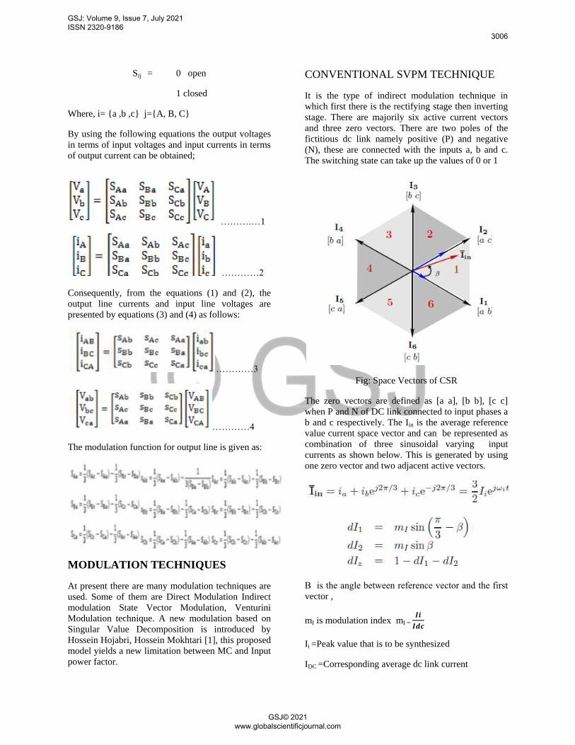
CONVENTIONAL SVPM TECHNIQUE
It is the type of indirect modulation technique in
which first there is the rectifying stage then inverting
stage. There are majorily six active current vectors
and three zero vectors. There are two poles of the
fictitious dc link namely positive (P) and negative
(N), these are connected with the inputs a, b and c.
The switching state can take up the values of 0 or 1
Fig: Space Vectors of CSR
The zero vectors are defined as [a a], [b b], [c c]
when P and N of DC link connected to input phases a
b and c respectively. The Iin is the average reference
value current space vector and can be represented as
combination of three sinusoidal varying input
currents as shown below. This is generated by using
one zero vector and two adjacent active vectors.
Β is the angle between reference vector and the first
vector ,
mI is modulation index mI
Ii =Peak value that is to be synthesized
IDC =Corresponding average dc link current
GSJ: Volume 9, Issue 7, July 2021 ISSN 2320-9186
3006
GSJ© 2021 www.globalscientificjournal.com

This modulation generates the pulsating DC-link
voltages as shown in following figure[16].
This all synthesizing was of the rectifying stage .
Fig: Instantaneous DC-link voltage waveform formed
The space vector diagram of inverting stage
comprises of six active and two zero vectors.
Fig: State vector of Voltage source Inverter
If the switching function is defined as Sy. When
switch is on Sy takes value of 1 and 0 when it is off.
The zero vectors switching states is [000] and [111]
where all the three outputs are connected to P or N of
DC link ,By the three phase output voltages Vo is as
the generated reference vector and given by-
This is generated by using one zero vectors and two
adjacent active vectors as given by following duty
ratio terms-
mV = modulation index
Vo= the peak output voltage that has to be
synthesized
Vi= Average DC link Voltage
The zero vectors are to be chosen carefully so as to
minimize the switching states.
The total output voltage generated by IMC is –
φi Input power factor Angle.
The total voltage transfer ratio of the IMC is given by
m which has a maximum value of 0.866.
DIRECT METHODS
The direct methods are also known as Venturini
method of matrix converter modulation. In this case
the main aim of this case is to generate variable
frequency and variable amplitude sinusoidal voltage
(vjN) from the fixed frequency and amplitude of input
voltage (Vi). A signal whose low frequency
component is the desired output voltage and the
signal that is used to synthesize such signal is the
instantaneous value of input voltage.The following
principle is used for the synthesizing signal:
Where, VjN is the low frequency component of jth
phase. tij is defined as the time during which switch
Sij is on and Ts as the sampling interval, vjN is the low-
frequency component that changes in every sampling
interval . By using this strategy a high frequency
switched output is generated. The expression for the
duty cycle is defined as following and by replacing
these values the output voltage expression in terms of
transfer matrix is expressed below [11].
GSJ: Volume 9, Issue 7, July 2021 ISSN 2320-9186
3007
GSJ© 2021 www.globalscientificjournal.com

= M(t)vi(t)
M(t) is the transfer matrix, and defined as
M(t) = ⟦
⟧
For current also following the analogous procedure it
can be shown as
(t) = MT(t)io(t)
where ii(t) is the low-frequency-component input
current vector, io(t) is the instantaneous value of
output current vector, MT(t) is the transpose of M(t).
(t) and equations are the basis of the
Venturini modulation method, leading to the
conclusion that the low-frequency components of the
output voltages are synthesized with the
instantaneous values of the input voltages and that
the low-frequency components of the input currents
are synthesized with the instantaneous values of the
output currents.
PROTECTION SCHEMES
The switches need to be protected in the event of
short circuit at input side and open circuit at the
output side. Protection for high current during
shorting of input terminals can be realized on the gate
drivers of the switches themselves. Standard
technique like sensing the collector to emitter voltage
across an IGBT to detect short circuit can be
employed. Interruption of load current, during
communication or due to activation of protection
circuit following any fault, may result in high voltage
at the output side. Normally a diode clamp circuit
along with a capacitor (Cc) and discharging resistor
(RC) is used to absorb the energy of inductive load.
MATRIX CONVERTER FED
INDUCTION MOTOR DRIVE
Speed control of induction motor with matrix
converter is presented in [21] with the help of
simulink tool in MATLAB. The P and N of the dc
link are substituted by the maximum positive and
maximum negative input line to neutral voltage. The
simulink model for the three phase induction motor
control with the help of matrix converter is shown in
the figure below. The carrier based modulation has
been implemented and used to control the induction
motor. Proposed method has been simulated in
MATLAB/Simulink and the simulation model is
shown.
Fig: MATLAB/Simulink model of the matrix
converter based induction motor control
Fig: Speed of the induction motor
GSJ: Volume 9, Issue 7, July 2021 ISSN 2320-9186
3008
GSJ© 2021 www.globalscientificjournal.com

APPLICATIONS AND ISSUES IN
MATRIX CONVERTER
The work [22] simulation results show that the
modulation algorithm provides a unity input
displacement factor even if the load has inductive
characteristics.The main disadvantages of MC for
like a like replacement for its use in industrial drive is
the low voltage transfer ratio. The most appropriate
load selected for its use is Induction motors since the
voltage transfer ratio is not an issue. The over
modulation problem was also accessed but due to that
the power quality of input side has to be sacrified in
favor of output drive capability. By changing some of
the topologies of indirect matrix converter but its
complexity increased has been presented in the work
and the size also has increased[12].
Fig: Stator current supplied to the induction motor
Fig.: Output voltages of the matrix converter
A fault tolerance topology developed which can be
efficiently used to drive a permanent magnet
synchronous motor for studying in the vital
applications with specifically emphasis on aerospace
applications[14]. The first integrated regenerative
frequency converter was developed [15], which may
be successfully used to drive a permanent magnet
synchronous motor (PMSM) for studies in crucial
applications with main emphasis on aerospace
applications. A 4KW motor prototype fed with
Matrix converter was developed using standard
frequency converter enclosure for testing industrial
application techniques [15].
REFERENCES
1. Hossein Hojabri, Hossein Mokhtari
and Liuchen Chang ―A Generalized
Technique of Modeling, Analysis, and
Control of a Matrix Converter Using SVD‖,
IEEE TRANSACTIONS ON INDUSTRIAL
ELECTRONICS, VOL. 58, NO. 3, MARCH
2011.
2. Khouloud Bedoud1, Tahar Bahi,
Sundarapandian Vaidyanathan, Hichem
Merabet, ―Control of Matrix Converter Fed
Induction Motor Drive‖, International
Journal of ChemTech Research Vol.10
No.2, 2017.
3. J. Rodríguez , E. Silva , F.
Blaabjerg , P. Wheeler , J. Clare & J. Pontt
―Matrix converter controlled with the direct
transfer function approach: analysis,
modelling and simulation‖, J, International
Journal of Electronics Vol. 92, No. 2,
February 2005
4. Hulusi Karaca, Ramazan Akkaya,
―Modelling and simulation of matrix
converter under distorted input voltage
conditions‖, Simulation Modeling Practice
and Theory 19 (2011) September 2010
5. Senad Huseinbegovic and Omer
Tanovic, ―Matrix Converter Based AC/DC
Rectifier‖, , IEEE Region 8 SIBIRCON-
2010, Irkutsk Listvyanka, Russia, July 11 —
15, 2010.
6. Pankaj Bisht, Akhilesh Dobhal,
―Modeling, Design and Analysis of Three
Phase Matrix Converter for Different
Loads‖, International Journal of Engineering
Research & Technology (IJERT) Vol. 3
Issue 9, September- 2014.
GSJ: Volume 9, Issue 7, July 2021 ISSN 2320-9186
3009
GSJ© 2021 www.globalscientificjournal.com

7. Liu Yong , He Yikang Hangzhou
―The Modeling and Simulation of a Three-
phase Matrix Converter ―College of
Electrical Engineering, Zhejiang University.
8. Simone Orcioni , Giorgio Biagetti , Paolo
Crippa and Laura Falaschetti , ―A Driving
Technique for AC-AC Direct Matrix
Converters Based on Sigma-Delta
Modulation‖ 18th International Conference
on Environment and Electrical Engineering.
9. Varsha Padhee Ashish Kumar
Sahoo Ned Mohan ―Modulation Techniques
for Enhanced Reduction in Common Mode
Voltage and Output Voltage Distortion in
Indirect Matrix Converters‖, IEEE
Transactions on Power Electronics 2016
10. Abdelkader Djahbara, Bouhani Benzianea,
Abdallah Zegaouia, ―A Novel Modulation
Method For Multilevel matrix converter‖
The International Conference on
Technologies and Materials for Renewable
Energy, Environment and Sustainability.
11. ―A Review of Control and Modulation
Methods for Matrix Converters‖, Jose
Rodriguez, Fellow, IEEE, Marco Rivera,
Member, IEEE, Johan W. Kolar, Fellow,
IEEE, and Patrick W. Wheeler, Member,
IEEE IEEE TRANSACTIONS ON
INDUSTRIAL ELECTRONICS, VOL. 59,
NO. 1, JANUARY 2012.
12. T. Wijekoon, C. Klumpner, P. Zanchetta,
and P. Wheeler, ―Implementation of a
Hybrid AC-AC Direct Power Converter
With Unity Voltage Transfer,‖ Power
Electronics, IEEE Transactions on, vol. 23,
no. 4, 2008.
13. Patrick W. Wheeler, Member, IEEE, José
Rodríguez, Senior Member, IEEE, Jon C.
Clare, Member, IEEE, Lee Empringham,
Member, IEEE, and Alejandro Weinstein,
―Matrix Converters: A Technology Review‖
IEEE TRANSACTIONS ON INDUSTRIAL
ELECTRONICS, VOL. 49, NO. 2, APRIL
2002
14. S. Khwan-on, L. De Lillo, L. Empringham ,
P.Wheeler, C. Gerada, ―Fault Tolerant,
Matrix converter, Permanent magnet
synchronous mototr drve for open cirvcuit
applications‖ Power electronics Machines
and control group, Depoartment of Electrical
and electronic Engineering, IET Power
applications, 2011
15. A new Matrix converter model for industry
applications Chistian Klumpner ,Member
,IEEE, Peter Nielsen, Ion bodea, Fellow
IEEE, Frede Blaabjerg Senior Member
IEEE.
16. A Dasgupta, P. Sensarma, ―Low-frequency
dynamic modelling and control of matrix
converter for power system applications‖
Vol. 5, Iss. 3, IET Power Electronics , 2011
17. S. Pinto, J. Silva ―Sliding mode direct
control of matrix converter‖ , IET Power
Applications Vol. 1, No. 3, May 2017.
18. Domenico Casadei, Associate Member,
IEEE, Giovanni Serra, Associate Member,
IEEE, Angelo Tani, and Luca Zarri ―Matrix
Converter Modulation Strategies: A New
General Approach Based on Space-Vector
Representation of the Switch State‖ IEEE
TRANSACTIONS ON INDUSTRIAL
ELECTRONICS, VOL. 49, NO. 2, APRIL
2002
19. Seung Ki Sul, Min Ho Park, ―A Novel
Technique for Optimal Efficiency Control of
a Current-Source Inverter-Fed Induction
Motor‖, IEEE TRANSACTIONS ON
POWER ELECTRONICS, VOL 3, NO 2,
APRIL 1988,
20. Marian P. Kazmierkowski, Leopoldo G.
Franquelo, Jose Rodriguez, Marcelo A.
Perez, and Jose I. Leon, ―High performance
motor drives‖ IEEE INDUSTRIAL
ELECTRONICS MAGAZINE
SEPTEMBER 2011
21. Vinod Battu, Grandhi Ramu, ―Simplified
Matrix Converter Fed Induction Motor
Drive‖
International Journal of Scientific &
Engineering Research, Volume 4, Issue 11,
November-2013 IJSER
GSJ: Volume 9, Issue 7, July 2021 ISSN 2320-9186
3010
GSJ© 2021 www.globalscientificjournal.com

22. Hulusi Karaca and Ramazan Akkaya,
―Modeling, Simulation and Analysis of
Matrix Converter Using Matlab and
Simulink‖, International Journal of
Modeling and Optimization January 2012
GSJ: Volume 9, Issue 7, July 2021 ISSN 2320-9186
3011
GSJ© 2021 www.globalscientificjournal.com