MATLAB/Simulink Model for Stability Studies of A Multi...
7
MATLAB/Simulink Model for Stability Studies of A Multi- Machine Power System incorporating Static VAR Compensator and Power System Stabilizers InshaMuzaffer, HailiyaAhsan, Mairajud-Din Mufti and S A Lone National Institute of Technology, Srinagar, India Abstract:This paper presents MATLAB/Simulink based modeling and transient stability simulation studies of a multi-machine power system, incorporated with power system stabilizers and static VAR compensator, working in a coordinated commitment to augment the system stability. A comprehensive, compact and user friendly model is developed by taking into consideration stator algebraic equations pertaining to the machines and the network equations. The compact model is then integrated with the differential equations pertaining to synchronous machines and other control systems. The model finally obtained is very versatile and can be used for transient stability studies under different scenarios. Effect of power systems stabilizers/and static VAR compensators on transient stability can be easily assessed/demonstrated with the proposed model. Few simulation experiments are conducted on WSCC 9-bus, 3-machine system to illustrate the efficacy of the developed MATLAB/Simulink model.The beauty of the proposed model is that it can be easily extended to include other FACTS and energy storage devices. Keywords:MATLAB/Simulink, Power system stabilizer, Static VAR Compensator, multi machine power system, transient stability. 1. Introduction The high level variability and uncertainty of load demand coupled with the stochastic and random behavior of the generation schemes of modern day power systems, primarily characterized by the increasing penetration of renewable sources creates new challenges for the operation and control of such networks. These parameters have a direct impact on the dynamic behavior of the system, thus affecting the most defining parameters of system stability, i.e. frequency, rotor angle variations and voltage of the system. Obviously, with the aim of achieving a reliable power system performance, any deviations in stability defining system factors should be eliminated swiftly. Thus, the stability of the system is the fundamental concern and assumes the kingpin position in power system study.[1][2] In this paper, the issue of transient stability has been addressed by implementing two distinguishing devices, viz., a power system stabilizer (PSS) and a dominant FACTS device called a static VAR compensator (SVC). Damping of oscillations, which is the prime issue in electric power system transient operation is boldly addressed by our suggested methodologies. In extreme situations, undamped oscillations have been a notorious cause of inevitable events like total black outs and may lead to certain prominent power quality problems.[3] PSS can be referred to as an extension of the synchronous generator[4] but an SVC holds the advantage of being located optimally at any suitable bus in the system. A combination of both PSS and SVC has been studied and implemented in our system modeling. In this paper, the widely known WSCC 9-bus, 3-machine system[5] has been taken up for experimental validation of the proposed scheme, as shown in Figure 1. 2International Conference on Engineering Research & Applications (ICERA) İstanbul (Turkey) May. 17-18, 2017 https://doi.org/10.15242/DIRPUB.DIR0517044 201
Transcript of MATLAB/Simulink Model for Stability Studies of A Multi...
MATLAB/Simulink Model for Stability Studies of A Multi-
Machine Power System incorporating Static VAR
Compensator and Power System Stabilizers
InshaMuzaffer, HailiyaAhsan, Mairajud-Din Mufti and S A Lone
National Institute of Technology, Srinagar, India
Abstract:This paper presents MATLAB/Simulink based modeling and transient stability simulation studies of a
multi-machine power system, incorporated with power system stabilizers and static VAR compensator, working
in a coordinated commitment to augment the system stability. A comprehensive, compact and user friendly model
is developed by taking into consideration stator algebraic equations pertaining to the machines and the network
equations. The compact model is then integrated with the differential equations pertaining to synchronous
machines and other control systems. The model finally obtained is very versatile and can be used for transient
stability studies under different scenarios. Effect of power systems stabilizers/and static VAR compensators on
transient stability can be easily assessed/demonstrated with the proposed model. Few simulation experiments are
conducted on WSCC 9-bus, 3-machine system to illustrate the efficacy of the developed MATLAB/Simulink
model.The beauty of the proposed model is that it can be easily extended to include other FACTS and energy
storage devices.
Keywords:MATLAB/Simulink, Power system stabilizer, Static VAR Compensator, multi machine power system,
transient stability.
1. Introduction
The high level variability and uncertainty of load demand coupled with the stochastic and random behavior
of the generation schemes of modern day power systems, primarily characterized by the increasing penetration
of renewable sources creates new challenges for the operation and control of such networks. These parameters
have a direct impact on the dynamic behavior of the system, thus affecting the most defining parameters of
system stability, i.e. frequency, rotor angle variations and voltage of the system. Obviously, with the aim of
achieving a reliable power system performance, any deviations in stability defining system factors should be
eliminated swiftly. Thus, the stability of the system is the fundamental concern and assumes the kingpin position
in power system study.[1][2]
In this paper, the issue of transient stability has been addressed by implementing two distinguishing devices,
viz., a power system stabilizer (PSS) and a dominant FACTS device called a static VAR compensator (SVC).
Damping of oscillations, which is the prime issue in electric power system transient operation is boldly
addressed by our suggested methodologies. In extreme situations, undamped oscillations have been a notorious
cause of inevitable events like total black outs and may lead to certain prominent power quality problems.[3]
PSS can be referred to as an extension of the synchronous generator[4] but an SVC holds the advantage of
being located optimally at any suitable bus in the system. A combination of both PSS and SVC has been studied
and implemented in our system modeling. In this paper, the widely known WSCC 9-bus, 3-machine system[5]
has been taken up for experimental validation of the proposed scheme, as shown in Figure 1.
2International Conference on Engineering Research & Applications
(ICERA) İstanbul (Turkey) May. 17-18, 2017
https://doi.org/10.15242/DIRPUB.DIR0517044 201

Fig.1: The WSCC 9-bus system with an SVC installed at bus 8
2. Power System Modeling
2.1. Multi-Machine System Model
Newton Raphson Load flow analysis[6] of the WSCCmulti-machine system yields the steady state values of
voltages, currents and power at all buses. For convenience, the general practice is to represent the transmission
network equations in the synchronously rotating frame of reference (D-Q frame). The D-axis also serves as the
reference for measuring the rotor angle δ of each machine. On the other hand, the swing equation and the
differential equations pertaining to the generator rotor circuit including the equations associated with the
generator excitation system are expressed in the rotor frame of reference (d-q frame). Accordingly, for transient
stability study it is imperative to transform the initial conditions of the multi-machine system in the more
conducive frame of reference. This transformation can be deduced from Figure 2 and equations (1-2).
(1)
(2)
Fig.2: DQ axis to dq axis transformation
The following equation depicts the rotational dynamics of a generator shaft.
(
)
(3)
The differential equations pertaining to the rotor are:
(4)
(
)
(5)
https://doi.org/10.15242/DIRPUB.DIR0517044 202
(6)
Equation (4) denotes the approximated flux dynamics of the rotor, equation (5) describes the flux dynamics
of a damper winding in quadrature to the field and equation (6) characterizes the feedback excitation control
system, as discussed comprehensively in[7].
The stator algebraic equations can be expressed as:
(7)
(8)
In order to account for the network mathematically, Kron’s reduction method is used to reduce the size of the
network by elimination of the passive nodes in the proposed model. This is realized with the help of a Matlab
function which not only provides flexibility in selecting the number of nodes to be eliminated but also offers to
compute the reduced network admittance matrix for different system conditions encountered while performing
the transient analysis, i.e. the conditions before fault, during fault and after fault. [Yred]being the reduced
admittance matrix, the network can be defined by equation (9).
[
] [ ] [
]
(9)
where the order of [Yred]is 3×3 for the basic test system comprising of three machines which are assumed to
be the only sources of current injection.
The complete model for transient stability study is arrived at by integrating the Simulink model for the
machines developed using equations (3-8) with the network function.
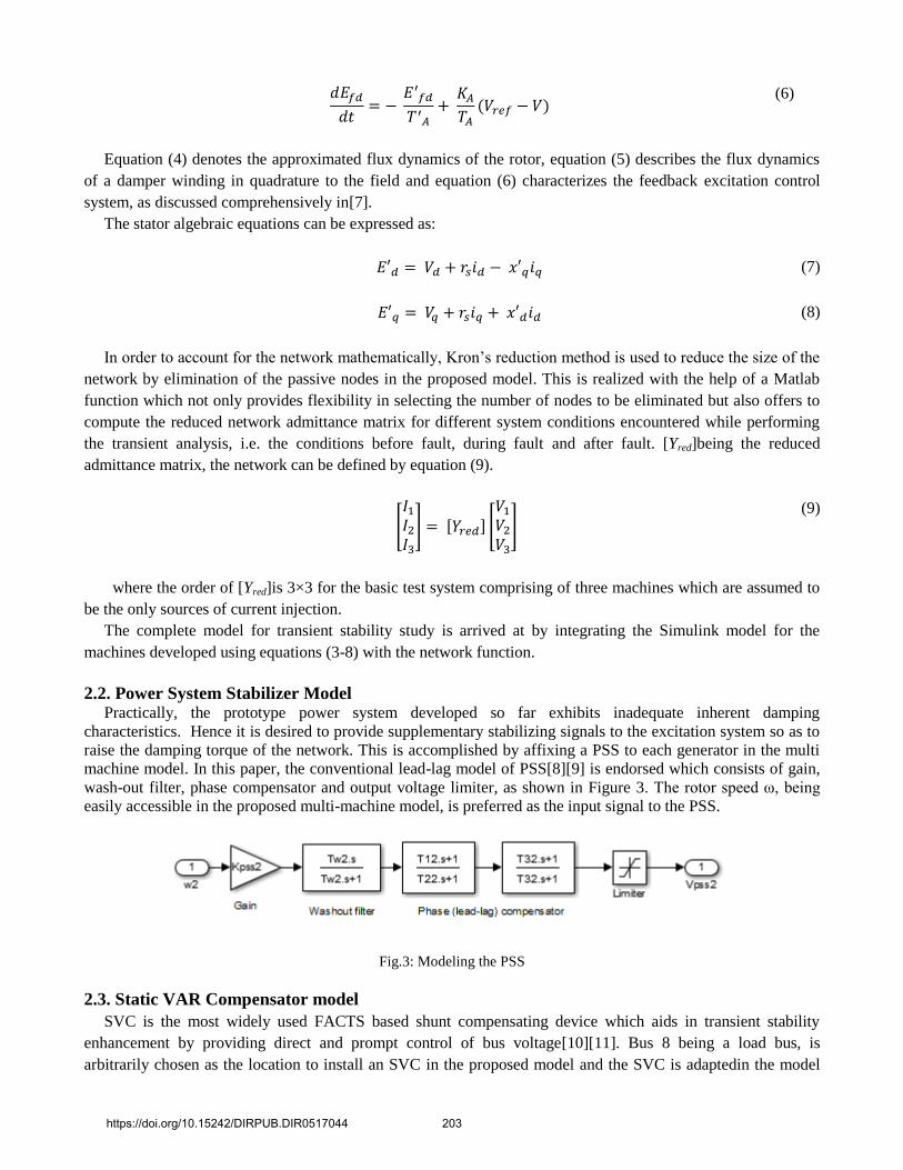
2.2. Power System Stabilizer Model Practically, the prototype power system developed so far exhibits inadequate inherent damping
characteristics. Hence it is desired to provide supplementary stabilizing signals to the excitation system so as to
raise the damping torque of the network. This is accomplished by affixing a PSS to each generator in the multi
machine model. In this paper, the conventional lead-lag model of PSS[8][9] is endorsed which consists of gain,
wash-out filter, phase compensator and output voltage limiter, as shown in Figure 3. The rotor speed ω, being
easily accessible in the proposed multi-machine model, is preferred as the input signal to the PSS.
Fig.3: Modeling the PSS
2.3. Static VAR Compensator model
SVC is the most widely used FACTS based shunt compensating device which aids in transient stability
enhancement by providing direct and prompt control of bus voltage[10][11]. Bus 8 being a load bus, is
arbitrarily chosen as the location to install an SVC in the proposed model and the SVC is adaptedin the model
https://doi.org/10.15242/DIRPUB.DIR0517044 203

such that its impacts can be observed on this bus as well as on the system as a whole. The SVC is incorporated
as part of a feedback loop that continuously keeps track of the voltage at bus 8 and accordingly controls its
parameters to present a variable susceptance at the bus. In this study, the proposed SVC is modeled as a current
injection source and consequently the order of [Yred] in the network function changes to 4×4. The current
injection by SVC is executed using equations (10-11), conventionally based on the DQ frame of reference.
[
] [
] [
]
(10)
Where [ ]
[
]
[ ]
[
]
[
]
[
] [
]
(11)
Fig.4: Modeling the SVC
3. Simulations and Results
3.1. Case A A three-phase fault is applied to the system near bus 8 on the line between buses 8 and 9, when simulation
time is equal to 1 second. The fault is cleared after 0.1 second duration by tripping off the line 8-9. The
corresponding rotor speed deviations for all the machines are plotted. The plots are shown in Figures 5-6. It can
be observed that the response of the system featuring just an SVC at bus 8 is oscillatory and does not show any
appreciable difference with the basic system. However, the system employed with PSS gives a significantly
damped response in comparison. A slight improvement over this can be seen in the response of the system
incorporated with both PSS and SVC. Figure 7 shows the voltage at bus 8. The role of SVC in maintaining the
bus voltage at its steady state value can be clearly seen.
https://doi.org/10.15242/DIRPUB.DIR0517044 204

Fig.5: Plot of rotor speed deviation of generator 2 with respect to generator 1 for case A
Fig.6: Plot of rotor speed deviation of generator 3 with respect to generator 1 for case A
Fig.7: Plot of voltage at bus 8 (i.e. the bus at which SVC is placed) for case A
3.2. Case B The system is subjected to a load disturbance such that the load connected at bus 8 undergoes a 10% change
at simulation time equal to 2 seconds. This load disturbance lasts on the system for duration of 3 seconds. The
corresponding plot of voltage at bus 8 is shown in Figure 8. It is observed that voltage is effectively maintained
near the steady state value in both systems employing SVC. Figures 9-10 show the corresponding rotor angle
deviation. It is observed that in both systems employing PSS, rotor speed oscillations are effectively taken care
of.
https://doi.org/10.15242/DIRPUB.DIR0517044 205

Fig.8: Plot of voltage at bus 8 (i.e. the bus at which SVC is placed) for case B
Fig.9: Plot of rotor speed deviation of generator 2 with respect to generator 1 for case B
Fig.10: Plot of rotor speed deviation of generator 3 with respect to generator 1 for case B
4. Conclusion
After studying and implementing a combination of both PSS and SVC in this study, it has been established
that not only stability of the system is ensured, but the possibility of increasing the transmittable power by
controlled damping of power system electromechanical oscillations is also accomplished. Also, the proposed
model is expedient in delivering a reasonable performance when the system load is changed stochastically as
well as deterministically. A significant feature of this model is its dexterousness and flexibility in being able to
conform to a variety of test scenarios and the scope it providesfor easily being extended to include other power
system stability enhancement devices like other FACTS devices and energy storage systems.
https://doi.org/10.15242/DIRPUB.DIR0517044 206
5. Reference
[1] Prabha Kundur, Power System Stability and Control, 1st ed. New York, USA: Mc Graw Hill, 1994.
[2] Peter W Sauer and M A Pai, Power system dynamics and stability, 1st ed. USA: Prentice Hall, 1998.
[3] M J Basler and R C Schaefer, "Understanding Power System Stability," in 58th Annual Conference for Protective Relay
Engineers, Texas, 2005, pp. 46-67.
https://doi.org/10.1109/CPRE.2005.1430421
[4] Adam Deysko, William E Leithead, and John O' Reilly, "Enhanced Power System Stability by Coordinated PSS
Design," IEEE Transactions on Power Systems, vol. 25, pp. 413-422, February 2010.
https://doi.org/10.1109/TPWRS.2009.2036704
[5] P M Anderson and A A Fouad, Power System Control and Stability, 2nd ed. USA: IOWA State University Press, 2002.
https://doi.org/10.1109/9780470545577
[6] Hadi Sadaat, Power System Analysis, 2nd ed. New York: McGraw-Hill, 2002.
[7] Aysen Demiroren and Serdar Ekinsi, "Modeling, Simulation and optimal design of power system stabilizers using ABC
algorithm," IJEEE, pp. 1532-1546, 2016.
[8] M Mary Linda and N Kesavan Nair, "Optimal design of multi-machine power system stabilizer using robust ant colony
optimization technique," Transactions of the Institute of Measurement and Control, vol. 34, no. 7, pp. 829-840, 2012.
https://doi.org/10.1177/0142331211421520
[9] D.A. Swann E.V. Larsen, "Applying Power System Stabilizers Part I: General Concepts.," IEEE Transactions on Power
Apparatus and Systems, vol. PAS 100, pp. 3025-33, June 1981.
[10] Salma Keskes, Wissem Bahloul, and M.B.A Kammoun, "Transient stability enhancement of power system equipped
with Power System Stabilizer by Static VAR Compensator," in 5th International Renewable Energy Congress 2014,
Tunisia, 2014.
[11] N G Hingorani and L Gyugyi, Understanding FACTS, 1st ed. New York, USA: IEEE Press, 2000..
https://doi.org/10.15242/DIRPUB.DIR0517044 207