
MATHEMATICAL STRUCTURAL ANALYSIS OF ONE · PDF fileMathematical structural analysis of one way...
20
Journal of Engineering Sciences, Assiut University, Vol. 39, No. 4, pp.761-780 July 2011 761 MATHEMATICAL STRUCTURAL ANALYSIS OF ONE WAY RIBBED SLABS M. H. Ahmed*, Y. A. Hassaneen*, Z. E. Abd El Shafy** and M. A. Farouk*** Civil engineering Department, faculty of Engineering, Assiut University * Professor at civil En. Dept., Faculty of Eng., Assiut University ** Lecturer, Civil Eng. Dept., Assiut University. *** Engineer Expert in Ministry of justice. (Received May 7, 2011 Accepted June 12, 2011) Mathematical structural analysis of one way ribbed slabs was introduced in this paper. The results of this analysis are compared with the results of the finite element method by SAP program. In SAP program, the model has been divided to frame elements "to represent ribs and beams" and shell elements "to represent the slab and solid part". Before using the SAP program to compare the results with the mathematical model, the results of the SAP program are evaluated by three dimension analysis through ANSYS program. The suggested mathematical analysis in this work was more accurate than the traditional method and gives close values of the induced moments of the ribs compared with the results of finite element method. 1- INTRODUCTION The ribbed slab is analyzed in the traditional method according to the Egyptian code as solid slab. In this method "traditional' the structural system of the ribs is considered as beams supported on main cross beams which are considered as rigid supports. The supporting beams are assumed to be simple if there is one bay slab and continues supporting beams if there are more then one bay. On this principle which is mentioned previously the bending moments are determined. As recommended in this method, solid parts have to be used at the connection of the ribs with the supported beam. These solid parts resist the internal forces which are higher than the loading capacity of the ribs without any effect on the internal forces. In the one way ribbed slab where the ribs are in one direction, it is assumed that the loads are distributed in the direction of the ribs only .so the load which is transferred through each rib is as follows :- w=W*s ……. (1) Where: w = the load of each rib /m` W = the load acted on slab/m 2 s = the distance between the ribs From the previous analysis of the ribbed slab in the traditional methods it is noted that the following assumptions are taken into consideration:- • The load completely transfers from the slab to the ribs regardless the stiffness of the slab and ribs.
Transcript of MATHEMATICAL STRUCTURAL ANALYSIS OF ONE · PDF fileMathematical structural analysis of one way...

Journal of Engineering Sciences, Assiut University, Vol. 39, No. 4, pp.761-780 July 2011
761
MATHEMATICAL STRUCTURAL ANALYSIS OF ONE WAY RIBBED SLABS
M. H. Ahmed*, Y. A. Hassaneen*, Z. E. Abd El Shafy** and M. A. Farouk*** Civil engineering Department, faculty of Engineering, Assiut University * Professor at civil En. Dept., Faculty of Eng., Assiut University ** Lecturer, Civil Eng. Dept., Assiut University. *** Engineer Expert in Ministry of justice.
(Received May 7, 2011 Accepted June 12, 2011)
Mathematical structural analysis of one way ribbed slabs was introduced in this paper. The results of this analysis are compared with the results of the finite element method by SAP program. In SAP program, the model has been divided to frame elements "to represent ribs and beams" and shell elements "to represent the slab and solid part". Before using the SAP program to compare the results with the mathematical model, the results of the SAP program are evaluated by three dimension analysis through ANSYS program. The suggested mathematical analysis in this work was more accurate than the traditional method and gives close values of the induced moments of the ribs compared with the results of finite element method.
1- INTRODUCTION
The ribbed slab is analyzed in the traditional method according to the Egyptian code as solid slab. In this method "traditional' the structural system of the ribs is considered as beams supported on main cross beams which are considered as rigid supports. The supporting beams are assumed to be simple if there is one bay slab and continues supporting beams if there are more then one bay. On this principle which is mentioned previously the bending moments are determined.
As recommended in this method, solid parts have to be used at the connection of the ribs with the supported beam. These solid parts resist the internal forces which are higher than the loading capacity of the ribs without any effect on the internal forces.
In the one way ribbed slab where the ribs are in one direction, it is assumed that the loads are distributed in the direction of the ribs only .so the load which is transferred through each rib is as follows :-
w=W*s ……. (1) Where: w = the load of each rib /m`
W = the load acted on slab/m2 s = the distance between the ribs From the previous analysis of the ribbed slab in the traditional methods it is
noted that the following assumptions are taken into consideration:- • The load completely transfers from the slab to the ribs regardless the stiffness
of the slab and ribs.
M. H. Ahmed et al.
762
• Ribs are supported on the beam which considering as rigid support. • Both the width and the thickness of solid parts have no effect on the behavior
of the rib. As a result of the previous discussion about the traditional method, there is
need to study other methods of analysis taking into account these factors using the finite element theory through sap 2000 program. The suggested model provides the behavior for ribbed slab by analyzing the structure as one-unite in two dimensions. In this method the structure is divided to frame elements and shell elements. Stiffens matrix for these elements are determined. This method takes into consideration the deformations happened in all elements such as vertical displacements and rotations in the two directions x,y ,and finding the internal forces produced in these elements.
2- DESCRIPTION OF FINITE ELEMENT METHOD
The slab has been divided to frame elements to represent ribs and beams, and shell elements to represent the slab and solid part. Frame and shell describe the cross-section of one or more elements.
Each frame element has its own local coordinate system used to define section properties and loads. The axes of this local system are denoted 1, 2 and 3. The first axis is directed along the length of the element; the remaining two axes lie in the plane perpendicular to the element with specified orientation.
Also each shell element has its own local coordinate system used to define material properties and loads. The axes of this local system are denoted 1, 2 and 3. The first two axes lie in the plane of the element with specified orientation; the third axis is normal to the plane.
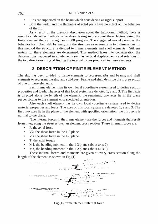
The internal forces in the frame element are the forces and moments that result from integrating the stresses over an element cross section. These internal forces are:
• P, the axial force • V2, the shear force in the 1-2 plane • V3, the shear force in the 1-3 plane • T, the axial torque • M2, the bending moment in the 1-3 plane (about axis 2) • M3, the bending moment in the 1-2 plane (about axis 3)
These internal forces and moments are given at every cross section along the length of the element as shown in Fig (1)
Fig (1) frame element internal force

MATHEMATICAL STRUCTURAL ANALYSIS OF ONE WAY …..
763
3- COMPARISON BETWEEN THE RESULTS OF FINITE ELEMENT METHOD AND TRADITIONAL METHOD
Two bays one way ribbed slab is analyzed by both traditional and finite element methods to determine the induced moments of the rib. The dimensions of each bay are 5.6x5.4m. The ribs have cross section 0.1x 0.25m and the space between ribs is 0.5m. The thickness of top slab equals to 0.05m. The cross section of edge beams is 0.25x0.7m and the cross section of middle beam is 0.3x0.9 m. the width of solid part in both direction equals to 0.3m. The Slab is subjected to uniform load 1 t/m2 and as shown in Fig.(2).
Fig (2) the model of analyzed slab
The B.M.Ds for the rib by the traditional method and finite element method by SAP program are shown in Figs (3) and (4) respectively.
Fig (3) B.M.D by traditional method
Fig (4) B.M.D by finite element method "SAP program"
Figures (3) and (4) show a great difference in the bending moments which are produced by the two methods "traditional method" and "finite element method".
The value of positive B.M of the rib in finite element method is 60.8% the B.M in the traditional method. And the value of maximum negative B.M at the connection
M. H. Ahmed et al.
764
between the rib and middle support in finite element method is 77.7% of the negative B.M in the traditional method
Also, in the finite element method, the effective equivalent load on the rib which causes the moments ( 1.MB , 2.MB ),is
)).()2
..((
8 212
MveBMveBMveB
lweq ++
−+−= ……. (2)
In the previous example, it was found that the equivalent load equals 0.467 t/m`, this means 93.4% of the total load "0.5 t/m`" is transferred by the rib and 6.6 % is transferred by slab. But in the traditional method 100 % of the load transfers by the rib.
As well as B.M at the connecting zone of the rib with the edge solid part is positive in the traditional method while it is clear in the finite element method, the B.M is negative at this connecting zone.
4- EVALUATION THE RESULTS OF SAP PROGRAM
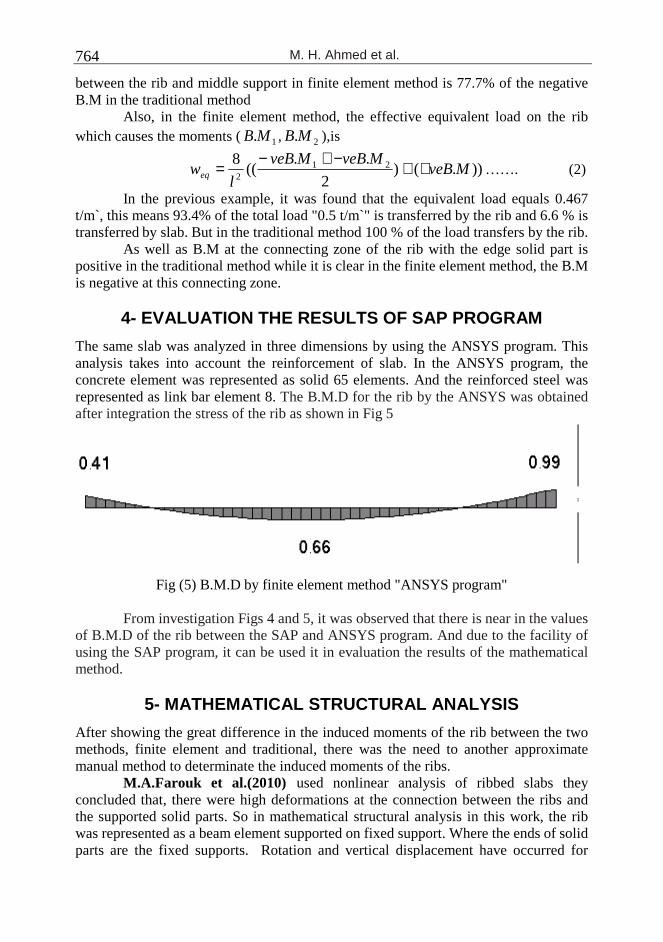
The same slab was analyzed in three dimensions by using the ANSYS program. This analysis takes into account the reinforcement of slab. In the ANSYS program, the concrete element was represented as solid 65 elements. And the reinforced steel was represented as link bar element 8. The B.M.D for the rib by the ANSYS was obtained after integration the stress of the rib as shown in Fig 5
Fig (5) B.M.D by finite element method "ANSYS program"
From investigation Figs 4 and 5, it was observed that there is near in the values of B.M.D of the rib between the SAP and ANSYS program. And due to the facility of using the SAP program, it can be used it in evaluation the results of the mathematical method.
5- MATHEMATICAL STRUCTURAL ANALYSIS
After showing the great difference in the induced moments of the rib between the two methods, finite element and traditional, there was the need to another approximate manual method to determinate the induced moments of the ribs.
M.A.Farouk et al.(2010) used nonlinear analysis of ribbed slabs they concluded that, there were high deformations at the connection between the ribs and the supported solid parts. So in mathematical structural analysis in this work, the rib was represented as a beam element supported on fixed support. Where the ends of solid parts are the fixed supports. Rotation and vertical displacement have occurred for

MATHEMATICAL STRUCTURAL ANALYSIS OF ONE WAY …..
765
these supports. The loads in this method are not transfer only by the ribs but there is role for the top slab in transferring this load as will be mentioned in section 4-3. The mathematical method in this work is not exact solution for analysis of one way ribbed slabs but it is more accurate than the traditional method as will be shown in the results. The slab in Fig (2) can be modeled according to the mathematical model as shown in Fig (6).
Fig (6) Mathematical model for the slab in Fig (2)
4-1 Determine the displacement and rotation at the ends of solid part:- To determine the displacement and rotation at the ends of solid part, firstly assume that the shear and moment reactions at the ends of the rib are fM and fQ or fmMλ and
sλ fQ .Where mλ , sλ are arbitrary factors to facilitate the convergence as will be
shown after. Considering that the solid parts as cantilever beams have depth equal to depth of the rib, width equal to the space between ribs and the span of these beams equal to the width of the solid part in the main model of ribbed slab. The supported beams in the main model are represented as spring supports for the solid parts as shown in Fig7. The stiffness of these springs are calculated with considering that the beams are subjected to constant distribution torsion and vertical load. Where:-
vbK : - the vertical stiffness of the supported beam =45
384
b
b
l
EI
bKθ : - rotation stiffness of the beam =bl
GJ2
8
Case (I) edge solid part:-
Analysis of the solid parts to determine the displacement and rotation at node 2 " 2δ ,
2θ " as shown in Fig 7
M. H. Ahmed et al.
766
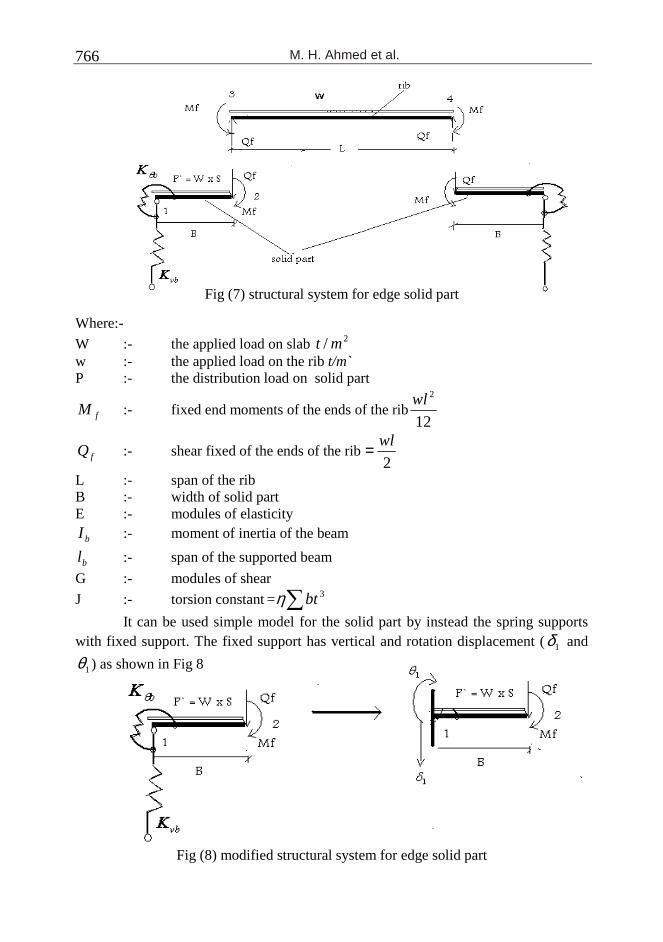
Fig (7) structural system for edge solid part
Where:-
W :- the applied load on slab 2/ mt w :- the applied load on the rib t/m ̀P :- the distribution load on solid part
fM :- fixed end moments of the ends of the rib12
2wl
fQ :- shear fixed of the ends of the rib 2
wl=
L :- span of the rib B :- width of solid part E :- modules of elasticity
bI :- moment of inertia of the beam
bl :- span of the supported beam
G :- modules of shear
J :- torsion constant =∑ 3btη
It can be used simple model for the solid part by instead the spring supports with fixed support. The fixed support has vertical and rotation displacement (1δ and
1θ ) as shown in Fig 8
Fig (8) modified structural system for edge solid part

MATHEMATICAL STRUCTURAL ANALYSIS OF ONE WAY …..
767
Where:-
11
vK
R=δ 1
1θ
θK
M=
R :the total vertical reaction M :the moment reaction By using the force method:-
b
t
vbftf
s K
BM
K
RpBMM
BM
B
EI θ
δ ++
−−+=
24)(
32
1 422
2 …… (3)
Effect of the applied load effect of the vertical displacement at node 1 effect of the rotation at node 1
b
ttf
s K
MpBMM
B
EI θ
θ +
−+=
12)(
2
1 3
2 … (4)
Where:-
sI :- moment of inertia of solid part as beam =12
3Sts
S :- space between rib and equal to width of solid part as beam R :- the reaction = fQpB+
tM :- total moment = ff MBQpB ++2
2
Case (II) middle solid part:-
When the solid part lies in between two ribs, determine δ and θ at the ends of solid part as follows:-
Fig (9) structural system for middle solid part

M. H. Ahmed et al.
768
By using the force method:-
b
rtL
b
rtr
vb
rfrtr
rfr
r
sr K
BM
K
BM
K
RpBMM
BM
B
EI θθ
δ −++
−−+=
24)(
32
1 422
3 …. (5)
θθ
θK
M
K
MpBMM
B
EItl
b
trrtrfr
r
sr −+
−+=
12)(
2
1 3
3 …. (6)
In similar for node 2L
b
Ltr
b
LtL
vb
LfLtL
rfL
L
sL K
BM
K
BM
K
RpBMM
BM
B
EI θθ
δ −++
−−+=
24)(
32
1 422
3 …. (7)
θθ
θK
M
K
MpBMM
B
EItr
b
tLLtLfL
L
sL −+
−+=
12)(
2
1 3
3 …. (8)
Where :
rB :- width of right solid part
LB :- width of left solid part
frQ :- fixed shear at the ends of right rib
fLQ :- fixed shear at the ends of left rib
frM :- fixed end moment of the right rib
fLM :- fixed end moment of the left rib
trM :- = fLrfrr MBQ
pB++
2
2
tLM :- = fLLfLL MBQ
pB++
2
2
4-2 Determine the moments at the ends of the rib:-
After obtaining the deformations at the ends of solid part δ and θ , it can be calculated the moments at the ends of the rib by using the force method as follows :-
Fig (10) the main system

MATHEMATICAL STRUCTURAL ANALYSIS OF ONE WAY …..
769
Fig (11-a) M0
Fig (11-b) M1
Fig (11-b) M 2
312211110 δδδδ −=++ XX …. (9)
322221120 θδδδ −=++ XX ….. (10)
Where :-
1X :- the vertical reaction at node 3
2X :- the moment at node 3
3δ :- vertical deflection at node 3
3θ :- rotation at node 3
lvEI
lw
EI
lw
r
r
r
r22
44
10 246θδ ++−= … (11-a)
… (11-b)
... (11-c)
lvEI
l
r22
3
11 3θδ ++= (11-d)
2
2
12 2θδ +=
rEI
l (11-e)
By substituting equations (11-a to 11-e) in equations (9and 10). , and solve these equations, we obtain:-
)(1
21
3
21
20
11
3
21
103 δ
θδδ
δδ
δδ −−+=
ZM ….. (12)
2
33
20 124θδ +−=
r
r
r
r
EI
lw
EI
lw
222 θδ +=rEI
l

M. H. Ahmed et al.
770
)(1
20223321
3 δδθδ
−−−= MR …. (13)
Where:-
11
12
21
22
δδ
δδ
−=Z
By applying M3, Q3, M2, Q2 in another trial on the solid parts and determine the deformations of the ends of solid parts another time. It can be stopped the trials until occurring the convergence between the last two trials.
4-3 The Applied Load on the Rib:-
As shown in the previous results that there was part of the load transfer by slab. M.A.Farouk et-al (2008) based on linear analysis for some ribbed slabs concluded that 28% of the load transfer by the slab and 72% of the load transfer by the rib.
In this section, eight slabs were analyzed by SAP program to try finding relation between the stiffness of slab to stiffness of rib and the applied load on the rib. The analyzed slabs are shown in table 1
Table (1)
``)1(12 2
3
ba
EtK s
s υ−= .
3N
l
EIK r =
MATHEMATICAL STRUCTURAL ANALYSIS OF ONE WAY …..
771
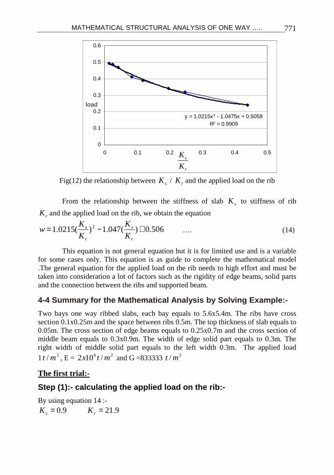
Fig(12) the relationship between sK / rK and the applied load on the rib
From the relationship between the stiffness of slab sK to stiffness of rib
rK and the applied load on the rib, we obtain the equation
506.0)(047.1)(0215.1 2 +−=r
s
r
s
K
K
K
Kw …. (14)
This equation is not general equation but it is for limited use and is a variable for some cases only. This equation is as guide to complete the mathematical model .The general equation for the applied load on the rib needs to high effort and must be taken into consideration a lot of factors such as the rigidity of edge beams, solid parts and the connection between the ribs and supported beam.
4-4 Summary for the Mathematical Analysis by Solving Example:-
Two bays one way ribbed slabs, each bay equals to 5.6x5.4m. The ribs have cross section 0.1x0.25m and the space between ribs 0.5m. The top thickness of slab equals to 0.05m. The cross section of edge beams equals to 0.25x0.7m and the cross section of middle beam equals to 0.3x0.9m. The width of edge solid part equals to 0.3m. The right width of middle solid part equals to the left width 0.3m. The applied load
1 2/ mt , E = 26 /102 mtx and G =833333 2/ mt
The first trial:-
Step (1):- calculating the applied load on the rib:-
By using equation 14 :- 9.0=sK 9.21=rK
y = 1.0215x2 - 1.0475x + 0.5058R2 = 0.9909
0
0.1
0.2
0.3
0.4
0.5
0.6
0 0.1 0.2 0.3 0.4 0.5
load
r
s
K
K

M. H. Ahmed et al.
772
22 /46.0506.0)9.21
9.0(047.1)
9.21
9.0(0215.1 mtw =+−=
Step (2):- calculating the displacement and rotation at the end of edge solid part:- Span of the beam =5.6m and cross section 0.25x0.7m
431014.7 mxI b−= 31025.4 −= xJ
45
384
l
EIK vb = = 1115 t/m
43
00065.012
5.0)25.0(m
xI s ==
Span of the rib = 5.4-0.6"solid parts" = 4.8m,, assume that mλ = 0.5 sλ =1.0
tmwl
Mr
f .44.012
7.05.02
==
twl
Q rf 1.1
2== fQpBR +=
tmMBQpB
M fft .97.02
2
=++=
By using equations 3 and 4 m0015.02 =δ
.00146.02 rad=θ
Step (3):- calculating the displacement and rotation at the ends of middle solid part:- The cross section of the middle beam is 0.3x0.9m
40182.0 mI b = 3104.6 −= xJ
mtl
EIK
b
bvb /2842
5384
4==
radtml
GJK
bb /.600
82
==θ

MATHEMATICAL STRUCTURAL ANALYSIS OF ONE WAY …..
773
radtml
GJK
bb /.1360
82
==θ
assume that mλ = sλ =1.0 . And because the two bays are equally :-
tmwl
MMr
fLfr .88.012
2
===
twl
QQ rfLfr 1.1
2===
tQQBBpR LrrL 5.2)( =+++=
tmMM tLtr .23.1==
By applying equations 5and 6
b
rtL
b
rtr
vb
rfrtr
rfr
r
srL K
BM
K
BM
K
RpBMM
BM
B
EI θθ
δδ −++
−−+==
24)(
32
1 422
33
=.001m
θθ
θθK
M
K
MpBMM
B
EItl
b
trrtrfr
r
srL −+
−+==
12)(
2
1 3
33
=0.00024rad.
Step (4) determine moments and reactions at the ends of the rib:-
Where the right bay equals to the left bay , it can be solve one bay as follows :-
By using equation 12 and 13 as follows:-
)(1
21
3
21
20
11
3
21
103 δ
θδδ
δδ
δδ −−+=
ZM
)(1
20223321
3 δδθδ
−−−= MR
Where :-
m0794.010 =δ m02107.020 =δ m0126.022 =δ m0352.012 =δ
m0957.011 =δ m0281.021 =δ 0805.0=Z We obtain: - M3 = 1.11 m.t R3 = 1.26t M2 = 0.35m.t R2 = 0.99t

M. H. Ahmed et al.
774
The second trial
By applying (M2 = 0.35m.t,, R2 = 0.99t ) on the edge solid part , applying (M3 = 1.11m.t R3 = 1.26t) on the middle solid part and resolution the steps 2 to 4 We obtain M3 = 1.02 m.t R3 = 1.22t M2 = 0.44m.t R2 = .99t
The third trial
Also by applying (M2 = 0.44m.t,, R2 = 0.99t ) on the edge solid part , applying (M3 = 1.02 m.t R3 = 1.22t) on the middle solid part and resolution the steps 2 to 4 We obtain M3 = 1.06 m.t R3 = 1.23t M2 = 0.39m.t R2 = .97t It was observed that near of the values between the last two trials. So it can be stopped the trials. By drawing the B.M.D to compare the results with the finite element and traditional methods
Fig (13-a )B.M.D by mathematical method
Fig (13-b) B.M.D by finite element method "SAP program"
Fig (13-c) B.M.D by traditional method
It can conclude that the obtained results by mathematical structural analysis are match with results by finite element method. As observed from the steps of solving the mathematical method that this method takes into account a lot of factors such as the rigidity of slab, rigidity of rib, rigidity of the solid parts and the beams.
4-5 Check the Efficiency of the Mathematical Models
Twenty four one way ribbed slabs were analyzed by the mathematical method, finite element method and traditional model to check the efficiency of the mathematical method. All slabs were two bays. These slabs were analyzed with change a lot of factors such as the depth of the rib, thickness of slab, width of solid parts, depth of

MATHEMATICAL STRUCTURAL ANALYSIS OF ONE WAY …..
775
edge beams, dimensions of slab and density of the load. The analyzed slabs and their results are shown in table 4 and Figures 14 to 21.
Table 2
Where:- M1 :- B.M at the connection between the rib and edge solid part M2 :- B.M at the connection between the rib and middle solid part M3 :- B.M at the middle of the rib
sSAPanalysiM
elMathMSSAPANALYSIMveMerrorof
"
"mod.""".max%
1
11 −=−
sSAPanalysiM
elMathMSSAPANALYSIMveMerrorof
"
"mod.""".max%
3
33 −=+

M. H. Ahmed et al.
776
Change the Depth of the Rib
Fig (14) relationship between depth of rib and calculated max.B.M by three methods
(SAP, Math. Model and traditional)
Change the thickness of slab
Fig (15) relationship between thickness of slab and calculated max.B.M by three methods (SAP, Math. Model and traditional)
Change the width of edge solid part
Fig (16) relationship between width of edge solid part and calculated max.B.M by three methods (SAP, Math. Model and traditional
-1.4
-1.2
-1
-0.8
-0.6
-0.4
-0.2
0
0 0.1 0.2 0.3 0.4 0.5
depth of rib
max
.-veM
SAP analysis
Math.model
traditional
average error-5.3%
0
0.2
0.4
0.6
0.8
1
1.2
0 0.1 0.2 0.3 0.4 0.5
depth of rib
max
.+ve
M
SAP analysis
Math.model
traditional
average error2.3%
0
0.2
0.4
0.6
0.8
1
1.2
0.04 0.05 0.06 0.07 0.08 0.09 0.1 0.11 0.12
thickness of slab
max
.+ve
M
SAP analysis
Math.model
traditional
average error6%
-1.4
-1.2
-1
-0.8
-0.6
-0.4
-0.2
0
0 0.02 0.04 0.06 0.08 0.1 0.12
thickness of slab
max
.-ve
M
SAP analysis
Math.model
traditional
average error-6.14%
-1.4
-1.2
-1
-0.8
-0.6
-0.4
-0.2
0
0.2 0.3 0.4 0.5 0.6 0.7
width of solid part
max
.-veM
SAP analysis
Math.model
traditional
average error-5%
0
0.2
0.4
0.6
0.8
1
1.2
0.04 0.05 0.06 0.07 0.08 0.09 0.1 0.11 0.12
width of solid part
max
.+ve
M
SAP analysis
Math.model
traditional
average error4.4%

MATHEMATICAL STRUCTURAL ANALYSIS OF ONE WAY …..
777
Change the depth of edge beam
Fig (17) relationship between depth of edge beam and calculated max.B.M by three methods (SAP, Math. Model and traditional
Change the rectangularity of slab
Fig (18) relationship between rectangularity of slab and calculated max.B.M by three
methods (SAP, Math. Model and traditional
Change the density of the load
Fig (19) relationship between density of load of and calculated max.B.M by three methods (SAP, Math. Model and traditional
-1.4
-1.2
-1
-0.8
-0.6
-0.4
-0.2
0
0.2 0.4 0.6 0.8 1 1.2 1.4
depth of edge beam
ma
x.-v
eM
SAP analysis
Math.model
traditional
average error-4.8%
0
0.2
0.4
0.6
0.8
1
1.2
0.3 0.5 0.7 0.9 1.1 1.3
depth of edge beam
max
.+ve
M
SAP analysis
Math.model
traditional
average error3.4%
-3
-2.5
-2
-1.5
-1
-0.5
0
0.6 0.7 0.8 0.9 1 1.1 1.2 1.3 1.4
rectangularty
max
.-ve
M
SAP analysis
Math.model
traditional
average error-4.8%
0
0.2
0.4
0.6
0.8
1
1.2
1.4
1.6
1.8
2
0.9 1 1.1 1.2 1.3 1.4
rectancularty
max
.+ve
M
SAP analysis
Math.model
traditional
average error6.1%
-3
-2.5
-2
-1.5
-1
-0.5
0
0.5 0.7 0.9 1.1 1.3 1.5
density of the load
max
.-veM
SAP analysis
Math.model
traditional
average error-4.3%
0
0.2
0.4
0.6
0.8
1
1.2
1.4
1.6
0.4 0.5 0.6 0.7 0.8 0.9 1 1.1 1.2 1.3 1.4
density of load
max
.+ve
M
SAP analysis
Math.model
traditional
average error5%

M. H. Ahmed et al.
778
Change the Length of Left Bay to the Length of Right Bay L1/L2 1- For large bay
Fig (20) relationship between L1/L2 and calculated max.B.M by three methods (SAP,
Math. Model and traditional
2- For small bay
Fig (21) relationship between L1/L2 and calculated max.B.M by three methods (SAP, Math. Model and traditional
From investigation the Figs (14 to 21), it was observed that the mathematical
method is accurate more than the traditional. The mathematical method gives satisfied results comparison with the results of finite element method. Where the percentage of error between the mathematical method and finite element method for all studied slabs doesn't exceed + 10%. This method tack into account a lot of factors as mentioned before.
CONCLUSIONS
The following conclusions have been drawn out of the presented study:- 1) There was great difference between the traditional method and finite element
method 2) The suggested mathematical analysis gives satisfied results comprised with the
results of finite element method. The percentage of error between the
-3
-2.5
-2
-1.5
-1
-0.5
0
0.8 1 1.2 1.4 1.6 1.8 2 2.2
L1/L2
max
.-veM
SAP analysis
Math.model
traditional
average error-4.0%
0
0.5
1
1.5
2
2.5
0 0.5 1 1.5 2 2.5 3
L1/L2
max
.+ve
M
SAP analysis
Math.model
traditional
average error6%
-3
-2.5
-2
-1.5
-1
-0.5
0
0.8 1 1.2 1.4 1.6 1.8 2 2.2
L1/L2
max
.-veM
SAP analysis
Math.model
traditional
average error-1.0%
-0.1
0.1
0.3
0.5
0.7
0.9
1.1
0 0.5 1 1.5 2 2.5 3
L1/L2
max
.+ve
M
SAP analysis
Math.model
traditional
average error3.5%

MATHEMATICAL STRUCTURAL ANALYSIS OF ONE WAY …..
779
mathematical model and finite element method for all studied slabs doesn't exceed + 10%.
3) The mathematical method takes into account a lot of factors such as the rigidity of slab, rigidity of rib, density the load, rectangularity of slab, rigidity of the solid parts and the beams.
4) The suggested mathematical method can be used in the future instead of the traditional method.
REFERENCES
1. Ahmed M. H., Hassaneen Y. A., Abd El Shafy. Z. E. And Farouk M. A. ( The Effect Of Solid Parts On Non-Linear Of One Way Ribbed Slabs) journal of engineering sciences Assiut , October 2010.
2. Ahmed M. H., Hassaneen Y. A., Abd El Shafy. Z. E. And Farouk M. A. ( The Effect Of Spaces And Reinforcements Of The Ribs On The Non-Linear Behavior Of One Way Ribbed Slabs) The Seventh Alexandria International Conference, December 2010.
3. Egyptian code for design and construction of reinforcement concrete structures . ECP 203,2007
4. Reddy, J.N. ‘An Introduction to the finite Element Method’ International student Edition, McGraw-Hill Book Company, (1984).
5. Rockey K.C, H.R. Evans and Griffiths ‘The Finite Element Method’ Britain (1975).
6. SAP2000 ‘Linear and nonlinear Static and Dynamic Analysis and Design of Three-Dimension Structures ‘ Computer and Structures, Inc. Berkeley, California, USA August 2004.
7. Soghair H.M, Aly. A.G , Ahmed M.H and Farouk M.A, (Structural Analysis Of Ribbed Slabs) journal of engineering sciences Assuit , march 2008

M. H. Ahmed et al.
780
للبالطات ذات االعصاب فى اتجاه واحد إنشائي رياضيتحليل
يتم تحليل البالطات ذات االعصاب فى كثير من كودات التصميم مثل الكود المصرى طبقا لقواعد
ال تأخذ فى االعتبار الكثير من العوامل مثل سمك " التقليديه"هذه الطريقه . التصميم للبالطات المصمته
هذا البحث تم تحليل مجموعه من البالطات ذات االعصاب فى اتجاه واحد فى.البالطه وعمق العصب
والتى x,yفى البعدين SAPكوحده واحده عن طريق نظرية العناصر المحدوده باستخدام برنامج
لذا . اوضحت ان هناك وجود فروق كبيره فى العزوم المتولده فى االعصاب بينها وبين الطريقه التقليديه
فقد تناول هذا البحث تصور . الى طريقه اخرى لحساب العزوم المتولده على االعصابكانت الحاجه
هذه الدعامات . رياضى لالعصاب المكونه للبالطه باعتبارها كمرات مرتكزه على دعامات مرنه لتحليل
من فقد تم تحليل مجموعه . تأخذ فى االعتبار االزاحات الحادثه فى االجزاء المصمته السانده لالعصاب
بمتغيرات كثيره مثل تغير عمق االعصاب وسمك SAP programالبالطات ذات االعصاب باستخدام
وتم مقارنة . الكمرات واالجزاء المصمته وكثافة الحمل الواقع على البالطه جساءةالبالطه وابعادها وتغير
فقد . ح فى هذا البحثالرياضى المقتر التحليلهذا التحليل بالنتائج التى تم الحصول عليها من خالل
بينت النتائج ان الفارق للعزوم القصوى المتولده على العصب بين كل من نظريه العناصر المحدوده
لذا كانت نتائج هذا %. 10+ الرياضى المقترح فى هذا البحث لم تتعدى نسبة خطأ قدرها التحليلوبين
.دال من الطريقه التقليديهمقبوله ويمكن لهذا النموذج ان يستخدم مستقبال ب التحليل


