Mathematical model and characteristics of parametric transformers
2
Correspondence MATHEMATICAL MODEL AND CHARACTER- ISTICS OF PARAMETRIC TRANSFORMERS In paper 1825B [IEE Proc. B, Electr. Power AppL, 1982, 129, (3), pp. 117-124] by E.S. Tez and Prof. I.R. Smith, the authors, in their introduction, refer to two of our very early papers [A, B], on the subject, but do not refer to subsequent publications which contain a full and comprehensive treatment of both the theory and modelling of parametric transformers. At the end of the second paragraph of their introduction, the authors state that we 'did not relate the form of the functions involved to the physical structure and again did not consider the process by which energy is transferred'. This deduction is clearly incorrect since, even in our original paper on the subject [A], a whole page was devoted to the mechanism of energy transfer and expressions were derived for the average power transferred between the input and output circuits of the transformer. A subsequent paper [C] dealing with the operation of the transformer between two busbars also considers the process of energy transfer and gives the power/angle characteristics of the device. In 1974, a Ph.D thesis [D] was completed, in which a full and comprehensive theory and analysis of the parametric transformer was given, including a rigorous derivation of the functional relationships between the MMFs and the fluxes in the two cores. These relationships were also published in another paper [E], which deals with the operation of the device as a frequency changer, and they have also appeared in a subsequent paper [F]. References D to F also include detailed expressions for the average power transferred under various modes of operation. A state-model representation of the parametric transformer is described in a paper [G], which also includes a numerical solution of the transformer equations and a method of measuring the leakage inductances. The control of parametric transformers using semiconductor devices has also been examined [H]. It is surprising that the authors are not aware of this vast amount of published work on the subject. Their paper hardly contains anything which has not already been published, in some form or another, in our papers or the references cited in them. Neither does it contain even a single paragraph on the subject of power and energy transfer in the device. Their statement in the introduction about previous analytical treatments 'based on an inaccurate representation of the magnetic behaviour of the device, it provides results of little practical value', is obviously false, since the analysis given in References C to F is based on the exact relationship between the flux in each core and the MMFs of the input and output windings. PROF. W.Z. FAM 5th July 1982 Department of Electrical Engineering Technical University of Nova Scotia PO Box 1000 Halifax Nova Scotia Canada B3J 2X4 We would like to thank Prof. Fam for the interest shown in our paper, although his comments seem to be based on a rather hasty reading without full attention being paid to much beyond the introduction. A more careful study would have made evident the differences from previous work and the new contribution that exists in the approach adopted for the investigation of parametric transformers. The subject area of the paper, which cannot obviously be regarded as the monopoly of any one group of workers, is one in which only few people, but including Prof Fam, have consistently shown interest in the past decade. The references in our paper were provided only as examples of previous work, and are clearly not claimed to be a full listing of previous publications on parametric transformers. From the view point of practicability, many papers, particularly those emanating from Japan where the in- terest has been diverted more to experimental investigations than to analytical considerations, were not included. However, it is intended that future publications will deal with various aspects of parametric transformers, including a review of their history containing a comprehensive list of references. It is clear from our paper that a parametric transformer is a combination of an electrically variable inductor (saturable reactor) and a capacitor. The saturable reactor may take any configuration which provides two parametrically coupled windings without any mutual flux coupling. As agreed by many authors, the two-C-core arrangement investigated in the paper is only one of the many possible forms for the saturable reactor. However, the magnetic circuit alone, without the capacitor, cannot be regarded as a parametric transformer, contrary to the explicit tendency [I] in much of the literature, which often associates the operational characteristics with the core structure rather than with the principles of parametric resonance. There has also been some confusion between the related but distinct phenomena of parametric resonance and ferromagnetic resonance. An accurate representation of the arrangement of the magnetic circuit is essential for an analytical treatment of the device. In our paper, this is based on the equivalence between the two-C-core arrangement of Fig. 3 and the bridged-core assembly of Fig. 5. The MMF/flux relationships, in the form F 2 = N 2 i 2 = F 2 (0 1; 0 2 ) (A) have been expressed in terms of the dimensions of the core and are given by eqn. 6. The form these expressions take has therefore been related directly to the structure of the device, and a mathematical model for the saturable reactor is com- plete as soon as the physical dimensions and the B/H charac- teristic of the core are known. For analytical studies of the parametric transformer, the BjH characteristic is expressed analytically, when the explicit analytical expressions for the MMF/flux relationships become as given by eqn. 8. It is clear that the introduction to our paper does not state that previous authors had not related the primary and secondary fluxes with their corresponding MMFs. Previous work [J, K] tends to rely on an empirical approach, with these relationships produced by first obtaining experimentally the MMF/flux curve and then using a computer-based curve-fitting process to provide explicit functions. However, both equations (eqns. 6 and 8) in our paper provide directly these functions in terms of the core dimensions. They also take into account the airgaps and those parts of the core structure in which flux interaction does not occur. When the work reported in our paper was completed, there was not, nor is there yet, any publication, giving such explicit expressions for the MMF functions, which makes possible an in-depth analytical treat- ment. In particular, the physical orthogonality of the two-C- core parametric transformer had usually led to the implicit but incorrect assumption that it contained a completely IEE PROC, Vol. 130, Pt. B, No. 1, JANUARY 1983 0143-7038/83/010060 + 02 $01.50/0 69
Transcript of Mathematical model and characteristics of parametric transformers
CorrespondenceMATHEMATICAL MODEL AND CHARACTER-ISTICS OF PARAMETRIC TRANSFORMERS
In paper 1825B [IEE Proc. B, Electr. Power AppL, 1982,129, (3), pp. 117-124] by E.S. Tez and Prof. I.R. Smith, theauthors, in their introduction, refer to two of our very earlypapers [A, B], on the subject, but do not refer to subsequentpublications which contain a full and comprehensive treatmentof both the theory and modelling of parametric transformers.
At the end of the second paragraph of their introduction,the authors state that we 'did not relate the form of thefunctions involved to the physical structure and again didnot consider the process by which energy is transferred'. Thisdeduction is clearly incorrect since, even in our original paperon the subject [A], a whole page was devoted to the mechanismof energy transfer and expressions were derived for the averagepower transferred between the input and output circuitsof the transformer.
A subsequent paper [C] dealing with the operation of thetransformer between two busbars also considers the processof energy transfer and gives the power/angle characteristicsof the device.
In 1974, a Ph.D thesis [D] was completed, in which a fulland comprehensive theory and analysis of the parametrictransformer was given, including a rigorous derivation of thefunctional relationships between the MMFs and the fluxes inthe two cores. These relationships were also published inanother paper [E], which deals with the operation of thedevice as a frequency changer, and they have also appeared ina subsequent paper [F]. References D to F also includedetailed expressions for the average power transferred undervarious modes of operation.
A state-model representation of the parametric transformeris described in a paper [G], which also includes a numericalsolution of the transformer equations and a method ofmeasuring the leakage inductances. The control of parametrictransformers using semiconductor devices has also beenexamined [H].
It is surprising that the authors are not aware of this vastamount of published work on the subject. Their paper hardlycontains anything which has not already been published, insome form or another, in our papers or the references cited inthem. Neither does it contain even a single paragraph on thesubject of power and energy transfer in the device. Theirstatement in the introduction about previous analyticaltreatments 'based on an inaccurate representation of themagnetic behaviour of the device, it provides results of littlepractical value', is obviously false, since the analysis given inReferences C to F is based on the exact relationship betweenthe flux in each core and the MMFs of the input and outputwindings.
PROF. W.Z. FAM5th July 1982
Department of Electrical EngineeringTechnical University of Nova ScotiaPO Box 1000HalifaxNova ScotiaCanada B3J 2X4
We would like to thank Prof. Fam for the interest shown inour paper, although his comments seem to be based on arather hasty reading without full attention being paid to muchbeyond the introduction. A more careful study would havemade evident the differences from previous work and the new
contribution that exists in the approach adopted for theinvestigation of parametric transformers. The subject area ofthe paper, which cannot obviously be regarded as the monopolyof any one group of workers, is one in which only few people,but including Prof Fam, have consistently shown interest inthe past decade. The references in our paper were providedonly as examples of previous work, and are clearly not claimedto be a full listing of previous publications on parametrictransformers. From the view point of practicability, manypapers, particularly those emanating from Japan where the in-terest has been diverted more to experimental investigationsthan to analytical considerations, were not included. However,it is intended that future publications will deal with variousaspects of parametric transformers, including a review oftheir history containing a comprehensive list of references.
It is clear from our paper that a parametric transformer is acombination of an electrically variable inductor (saturablereactor) and a capacitor. The saturable reactor may take anyconfiguration which provides two parametrically coupledwindings without any mutual flux coupling. As agreed bymany authors, the two-C-core arrangement investigated in thepaper is only one of the many possible forms for the saturablereactor. However, the magnetic circuit alone, without thecapacitor, cannot be regarded as a parametric transformer,contrary to the explicit tendency [I] in much of the literature,which often associates the operational characteristics with thecore structure rather than with the principles of parametricresonance. There has also been some confusion between therelated but distinct phenomena of parametric resonance andferromagnetic resonance.
An accurate representation of the arrangement of themagnetic circuit is essential for an analytical treatment of thedevice. In our paper, this is based on the equivalence betweenthe two-C-core arrangement of Fig. 3 and the bridged-coreassembly of Fig. 5. The MMF/flux relationships, in the form
F2 = N2i2 = F 2 (0 1 ; 0 2 )(A)
have been expressed in terms of the dimensions of the coreand are given by eqn. 6. The form these expressions take hastherefore been related directly to the structure of the device,and a mathematical model for the saturable reactor is com-plete as soon as the physical dimensions and the B/H charac-teristic of the core are known. For analytical studies of theparametric transformer, the BjH characteristic is expressedanalytically, when the explicit analytical expressions for theMMF/flux relationships become as given by eqn. 8.
It is clear that the introduction to our paper does notstate that previous authors had not related the primary andsecondary fluxes with their corresponding MMFs. Previouswork [J, K] tends to rely on an empirical approach, with theserelationships produced by first obtaining experimentally theMMF/flux curve and then using a computer-based curve-fittingprocess to provide explicit functions. However, both equations(eqns. 6 and 8) in our paper provide directly these functionsin terms of the core dimensions. They also take into accountthe airgaps and those parts of the core structure in whichflux interaction does not occur. When the work reported inour paper was completed, there was not, nor is there yet, anypublication, giving such explicit expressions for the MMFfunctions, which makes possible an in-depth analytical treat-ment. In particular, the physical orthogonality of the two-C-core parametric transformer had usually led to the implicitbut incorrect assumption that it contained a completely
IEE PROC, Vol. 130, Pt. B, No. 1, JANUARY 1983 0143-7038/83/010060 + 02 $01.50/0 69
orthogonal flux system. Although, in the later work, Prof. Famcorrectly recognises the two-C-core arrangement as a parallelflux system, the magnetic descriptions proposed by him inthe form [I-L]
02 =(B)
consider, in effect, only those regions of the core common toboth the primary and the secondary magnetic circuits.
0.45 0.90 1.35pr imary MMF F,, kAt
1.80
4.Or
0.6 1.2pr imary MMF
1.8,kA t
3.0
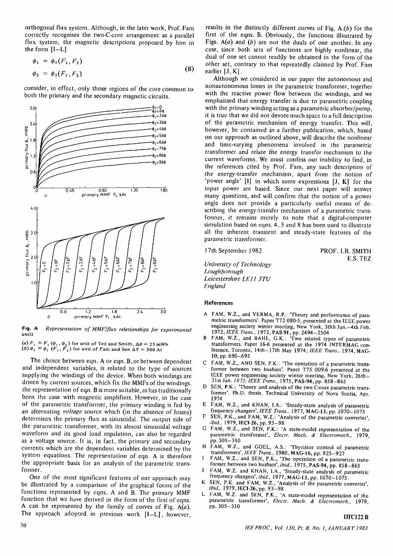
Fig. A Representation of MMF/flux relationships for experimentalunits
(a) F\ = F , (0, ,<f)2) for unit of Tez and Smith, A<t> - 25 mWb(6)0, = 0 , (F, ,F2) for unit of Fam and Sen AF = 300 At
The choice between eqn. A or eqn. B, or between dependentand independent variables, is related to the type of sourcessupplying the windings of the device. When both windings aredriven by current sources, which fix the MMFsof the windings,the representation of eqn. Bis more suitable, as has traditionallybeen the case with magnetic amplifiers. However, in the caseof the parametric transformer, the primary winding is fed byan alternating voltage source which (in the absence of losses)determines the primary flux as sinusoidal. The output side ofthe parametric transformer, with its almost sinusoidal voltagewaveform and its good load regulation, can also be regardedas a voltage source. It is, in fact, the primary and secondarycurrents which are the dependent variables determined by thesystem equations. The representation of eqn. A is thereforethe appropriate basis for an analysis of the parametric trans-former.
One of the most significant features of our approach maybe illustrated by a comparison of the graphical forms of thefunctions represented by eqns. A and B. The primary MMFfunction that we have derived in the form of the first of eqns.A can be represented by the family of curves of Fig. A(a).The approach adopted in previous work [ I -L] , however,
70
results in the distinctly different curves of Fig. A.(6) for thefirst of the eqns. B. Obviously, the functions illustrated byFigs. A(a) and (b) are not the duals of one another. In anycase, since both sets of functions are highly nonlinear, thedual of one set cannot readily be obtained in the form of theother set, contrary to that repreatedly claimed by Prof. Famearlier [J, K].
Although we considered in our paper the autonomous andnonautonomous losses in the parametric transformer, togetherwith the reactive power flow between the windings, and weemphasised that energy transfer is due to parametric couplingwith the primary winding acting as a parametric absorber/pump,it is true that we did not devote much space to a full descriptionof the parametric mechanism of energy transfer. This will,however, be contained in a further publication, which, basedon our approach as outlined above, will describe the nonlinearand time-varying phenomena involved in the parametrictransformer and relate the energy transfer mechanism to thecurrent waveforms. We must confess our inability to find, inthe references cited by Prof. Fam, any such description ofthe energy-transfer mechanism, apart from the notion of'power angle' [I] in which some expressions [J, K] for theinput power are based. Since our next paper will answermany questions, and will confirm that the notion of a powerangle does not provide a particularly useful means of de-scribing the energy-transfer mechanism of a parametric trans-former, it remains merely to note that a digital-computersimulation based on eqns. 4, 5 and 8 has been used to illustrateall the inherent transient and steady-state features of theparametric transformer.
PROF. I.R. SMITHE.S. TEZ
17th September 1982
University of TechnologyLoughboroughLeicestershire LEI I 3TUEngland
References
A FAM, W.Z., and VERMA, R.P.: 'Theory and performance of para-metric transformers'. Paper T72 080-5, presented at the IEEE powerengineering society winter meeting, New York, 30th Jan.-4th Feb.1972; IEEE Trans., 1972, PAS-91, pp. 2494-2504
B FAM, W.Z., and BAHL, G.K.: 'Two related types of parametrictransformers. Paper 16-6 presented at the 1974 INTERMAG con-ference, Toronto, 14th-17th May 1974; IEEE Trans., 1974, MAG-10, pp. 690-693
C FAM, W.Z., AND SEN, P.K.: "The operation of a parametric trans-former between two busbars'. Paper T75 009-6 presented at theIEEE power engineering society winter meeting, New York, 26th-31st Jan. 1975; IEEE Trans., 1975, PAS-94, pp. 858-865
D SEN, P.K.: 'Theory and analysis of the two C-core parametric trans-former'. Ph.D. thesis, Technical University of Nova Scotia, Apr1974
E FAM, W.Z., and KHAN, I.A.: 'Steady-state analysis of parametricfrequency changers', IEEE Trans., 1977, MAG-13, pp. 1070-1075
F SEN, P.K., and FAM, W.Z.: 'Analysis of the parametric converter'ibid., 1979, IECI-26, pp. 93-98
G FAM, W.Z., and SEN, P.K.: 'A state-model representation of theparametric transformer', Electr. Mach. & Electromech., 1979,pp. 305-310FAM, W.Z., and GOEL, A.S.: 'Thyristor control of parametrictransformers', IEEE Trans., 1980, MAG-16, pp. 925-927FAM, W.Z., and SEN, P.K., 'The operation of a parametric trans-former between two busbars', ibid., 1975, PAS-94, pp. 858-865FAM, W.Z. and KHAN, I.A., 'Steady-state analysis of parametricfrequency changers', ibid., 1977, MAG-13, pp. 1070-1075SEN, P.K. and FAM, W.Z., 'Analysis of the parametric converter'ibid., 1979, IECI-26, pp. 93-98FAM, W.Z. and SEN, P.K., 'A state-model representation of theparametric transformer', Electr. Mach. & Electromech 1979pp. 305-310
DTC122B
IEEPROC, Vol. 130, Pt. B, No. 1, JANUAR Y 1983
H
K