
MATERIALS TESTING - Universidad de Guanajuato de... · Direct shear and torsional shear are ... the...
66
MATERIALS TESTING
Transcript of MATERIALS TESTING - Universidad de Guanajuato de... · Direct shear and torsional shear are ... the...

MATERIALS TESTING

Why are metals tested ?
Ensure quality Test properties Prevent failure in use Make informed choices in using materials Factor of Safety is the ratio comparing the
actual stress on a material and the safe useable stress.
Two forms of testing
Mechanical tests – the material may be physically tested to destruction. Will normally specify a value for properties such as strength, hardness, toughness, etc.
Non-destructive tests (NDT) – samples or finished articles are tested before being used.

HARDNESS TESTING Hardness is the ability to withstand
indentation or scratches.

Hardness testing machine
The indenter is pressed into the metal
Softer materials leave a deeper indentation

Hardness testing machine
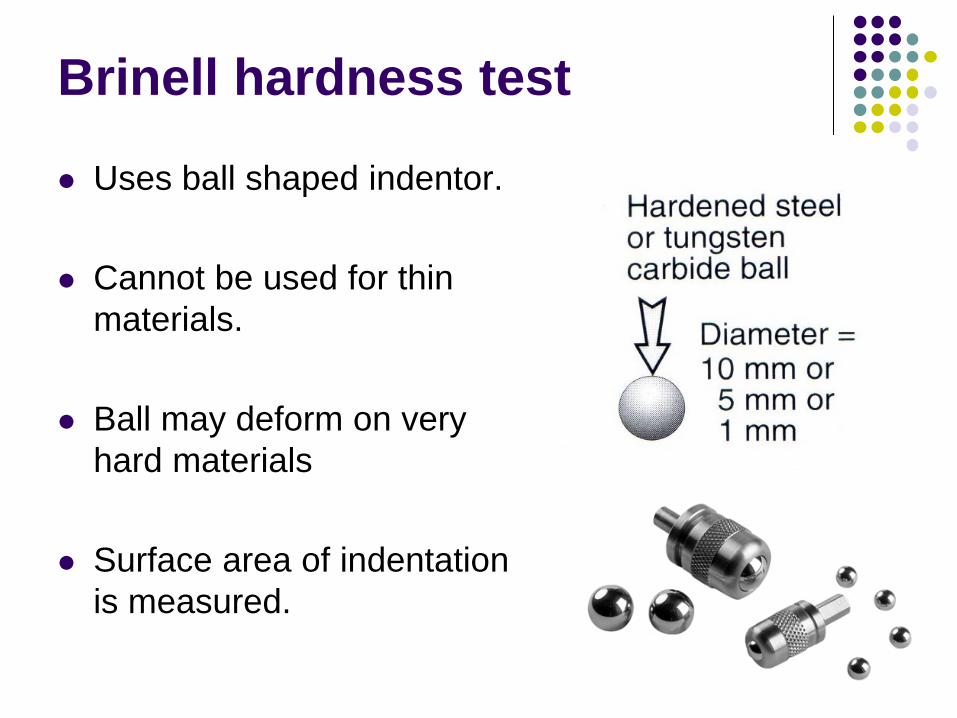
Brinell hardness test
Uses ball shaped indentor.
Cannot be used for thin materials.
Ball may deform on very hard materials
Surface area of indentation is measured.

Vickers hardness test
Uses square shaped pyramid indentor.
Accurate results.
Measures length of diagonal on indentation.
Usually used on very hard materials

Rockwell hardness tests Gives direct reading.
Rockwell B (ball) used for
soft materials.
Rockwell C (cone) uses diamond cone for hard materials.
Flexible, quick and easy to use.

Impact Tests
Toughness of metals is the ability to withstand impact.


Izod test Strikes at 167 Joules.
Test specimen is held
vertically.
Notch faces striker.

Charpy impact test Strikes form higher
position with 300 Joules.
Test specimen is held horizontally.
Notch faces away from striker.

Tensile Testing
Uses an extensometer to apply measured force to an test specimen. The amount of extension can be measured and graphed.
Variables such as strain, stress, elasticity, tensile strength, ductility and shear strength can be gauged.
Test specimens can be round or flat.
15
•Tensile loads are those that tend to pull the specimen apart, putting the specimen in tension. They can be performed on any specimen of known cross-sectional area and gage length to which a uniform tensile load can be applied. •Tensile tests are used to determine the mechanical behavior of materials under static, axial tensile, or stretch loading.
•ASTM standards for common tensile tests may be found in sections E8 (metals), D638 (plastics), D2343 (fibers), D897 (adhesives), D987 (paper), and D412 (rubber).
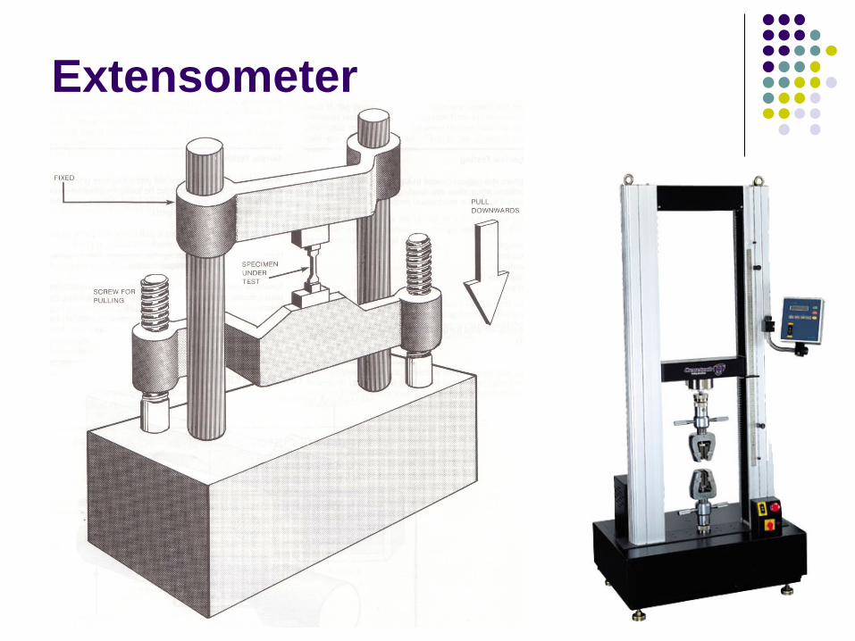
Extensometer

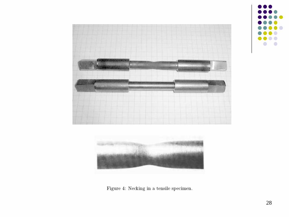
Tensile test specimens


Test results Cup and cone fracture signifies a ductile material
A shear fracture would indicate a brittle material

Producing graphs
Two basic graphs: Load / extension graph. Stress / strain graph.


Draw graph for this tensile test?
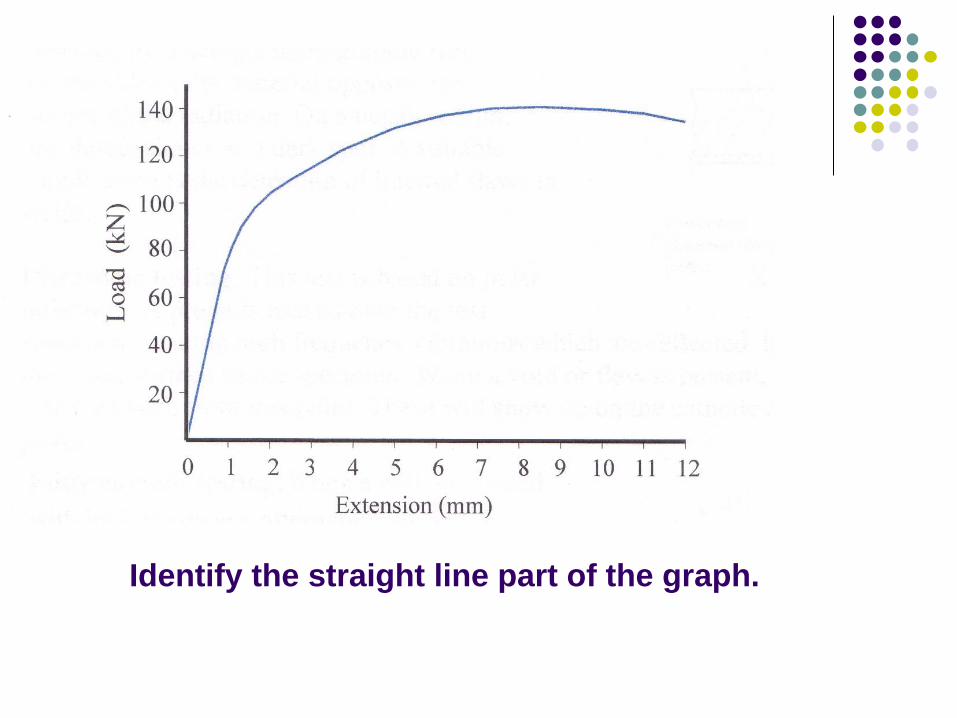
Identify the straight line part of the graph.

25
Stress-Strain Curve
This stress-strain curve is produced from the tensile test.

26
28

29
Stress Strain for Different Materials
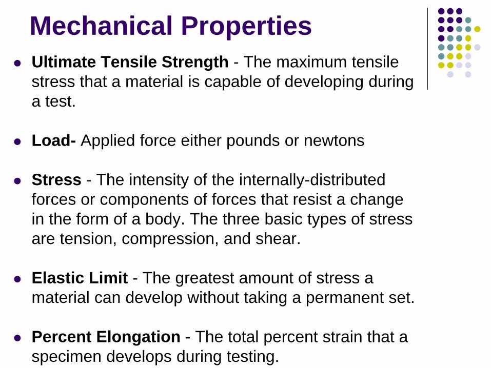
Mechanical Properties Ultimate Tensile Strength - The maximum tensile
stress that a material is capable of developing during a test.
Load- Applied force either pounds or newtons
Stress - The intensity of the internally-distributed forces or components of forces that resist a change in the form of a body. The three basic types of stress are tension, compression, and shear.
Elastic Limit - The greatest amount of stress a material can develop without taking a permanent set.
Percent Elongation - The total percent strain that a specimen develops during testing.

31
The engineering stress is:
P is the load in lbs. on the specimen and A0 is the original cross-sectional area near the center of the specimen. On the other hand, the true stress is the load divided by the true area, which continues to be smaller by the tensile load. The true stress continues to increase to the point of fracture, while the engineering stress decreases to the point of fracture due to the increasing load and the constant cross-sectional area.
0
PA
σ =

32
The engineering strain is:
0
0
l ll
ε −=
l is the gage length at a given load and l0 is the original gage length with zero load

Youngs Modulus (E)
E = Stress Strain
Stress = Load Cross section area Strain = Extension Original length
εσ
=E

Youngs Modulus for stress – strain graph Select point on elastic
part of graph
Calculate Youngs Modulus with this point
E = Stress Strain

Youngs Modulus for Load –extension graph

Proof Stress
The stress that causes a % increase in gauge length.
It can be found by drawing a line parallel to the straight part of the graph.
A value can be taken from the vertical axis.

Proof stress for Load – Extension graph

Proof stress for Stress – Strain graph

Tensile Strength
Tensile strength = Maximum Load Cross section area Maximum load is the highest point on the graph. Often called Ultimate Tensile Strength (UTS)

Creep
When a weight is hung from a piece of lead and left for a number of days the lead will stretch. This is said to be creep. Problems with creep increase when the materials are subject to high temperature or the materials themselves have low melting points such as lead. Creep can cause materials to fail at a stress well below there tensile strength.

Fatigue Fatigue is due to the repeated loading and unloading. When a material is subjected to a force acting in different
directions at different times it can cause cracking. In time this causes the material to fail at a load that is much less than its tensile strength, this is fatigue failure. Vibration for example is a serious cause of fatigue failure.
Fatigue can be prevented with good design practice. 1. A smooth surface finish reduces the chance of surface cracking. 2. Sharp corners should be avoided. 3. Corrosion should be avoided as this can cause fatigue cracks.


43
Introduction
• Simplistically, compression testing is the opposite of tensile testing. A compressive load tends to squeeze or compact the specimen. The choice of a compression test over other types of testing largely depends on the type of loading the material will see during application or service. • Metals and many plastics, for example, are more efficient at resisting tensile loads. Therefore, they are more commonly tested using tensile loading, depending on the application, of course. Materials, such as concrete, brick, and some ceramic products, are more often used in applications for their compressive loading properties and are, therefore, tested in compression.
Compression Testing

44
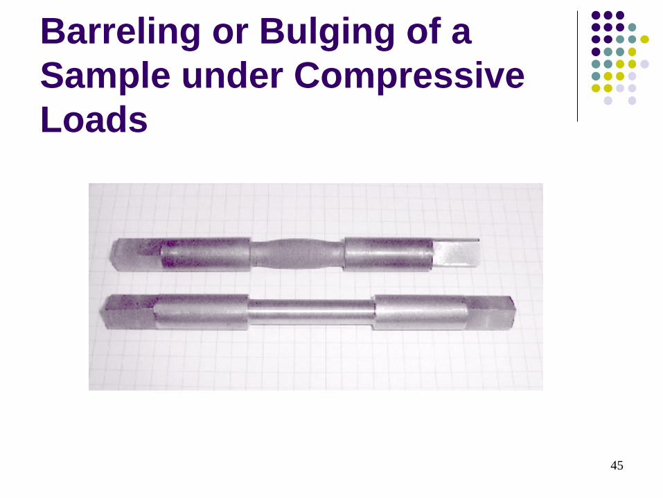
Compression Testing – Procedure During a typical compression test, data are collected regarding the applied load, resultant deformation or deflection, and condition of the specimen. For brittle materials, the compressive strength is relatively easy to obtain, showing marked failure. However, for ductile materials, the compressive strength is generally based on an arbitrary deformation value. Ductile materials do not exhibit the sudden fractures that brittle materials present. They tend to buckle and "barrel out".
45
Barreling or Bulging of a Sample under Compressive Loads

Disk Test Compression test developed
for brittle materials such as ceramics and glass.
A disk shaped specimen is loaded between to solid platens. Tensile stresses build up perpendicular to the centerline along the disk, fracture begins, and the disk will split vertically.
Tensile stress from this test can be calculated with the following equation: σ = 2P/πdt P is load at fracture, d is diameter of disk, t is thickness.

47
•Prior to this and any test, the dimensions of the specimen should be measured with adequate precision using proper instruments. Once these measurements have been taken and recorded, the specimen should be loaded into the testing machine. •In compression testing, and testing in general, care should be taken to insure that the axis of the specimen is centered and aligned with the axis of loading. •Loading rates should be steady and continuous. Rates vary, but a general figure is 0.005 inches per minute strain rate. Loading rates typically range from 500-1000 lb/min.
48
•As in most tests of mechanical properties, the loading rate can adversely affect the results if you get carried away. Loading continues at this rate up to approximately one-half of the anticipated strength and, then, should be reduced to allow for more frequent data collection. In this way, subtle changes can be observed in the specimen's behavior. •As in all of these tests, please observe proper safety procedures. Obtain and properly wear personal protective equipment. Some of these materials exhibit violent fractures with explosive results.

49
Introduction •Shear testing involves an applied force or load that acts in a direction parallel to the plane in which the load is applied. Shear loads act differently than, say, tensile or compressive loads that act normal or perpendicular to the axis of loading. Direct shear and torsional shear are important forces used to determine shear properties. Direct or torsional loading depends on the forces a material is expected to be subjected to during service.
Shear Testing

50
Procedure •Before testing, the specimen is accurately measured using proper instruments and the gage length is marked. The troptometer or a suitable replacement is attached to the specimen and zeroed out. Proper precautions should be taken to center the specimen in the machine or fixture. The grippers are tightened to insure against slippage, yet not so tight as to cause deformations which would affect test results. •In general, shear testing involves either direct or torsional loading. In direct shear tests, the specimen is placed in the shear test fixture and a load is applied. This can be seen in the figure below. For plate specimens, a punch and die combination may be used. Plastics, generally, are square specimens with holes in either end to facilitate gripping. The applied load and resultant deformation are recorded and a suitable graph can be plotted.
Shear Testing

51
Shear Testing

Torsion Test In addition to tension and compression, a work-piece
may be subjected to shear strains. Punching holes in sheet metal. Metal cutting.
Torsion test used for determination of properties in “shear.” Usually performed on a thin tubular specimen.
Shear stress can be calculated with formula: T/2πr2t T is torque, r is average radius of tube, t is thickness of tube.
Shear strain is calculated with formula: rФ/l r is radius of tube, Ф is angle of twist in radians, and l is length of
tube.

Torsion Test
The ratio of the shear stress to the shear strain in the elastic range is known as the shear modulus or modulus of rigidity.
The angle of twist, Ф, to fracture in the torsion of solid round bars and elevated temp can help estimate forge-ability of metals.

Bending
Preparing specimens from brittle materials, such as ceramics and carbides, is difficult because of problems in shaping and machining them to certain dimensions.
The most common test for brittle materials is the bend or flexure test.

Bend / Flexure Test Rectangular specimen
supported at its ends. Load is applied vertically
at 1 or 2 pts. The stress at fracture in
bending is known as the modulus of rupture, flexural strength, or transverse rupture strength.

Non-destructive testing (NDT)

Why use NDT?
Components are not destroyed Can test for internal flaws Useful for valuable components Can test components that are in use

Penetrant testing
Used for surface flaws. The oil and chalk test is a traditional version
of this type of testing. Coloured dyes are now used.


Magnetic particle testing • Used for ferrous metals. • Detects flaws close to the surface of the material. • The component to be tested must first be
magnetized. • Magnetic particles which can be dry or in solution
are sprinkled onto the test piece. • The particles stick to the magnetic field and flaws
can be inspected visually by examining the pattern to see if it has been distorted.
• The component must be demagnetized after testing.


Eddy current testing Used for non-ferrous metals A.C. current is passed through the coil. The test piece is passed under the coil
causing secondary currents called eddy currents to flow through the test piece. This causes a magnetic field to flow in the test piece.
The flaws are detected on an oscilloscope by measuring a change in the magnetic field.

Ultrasonic testing Ultrasonic Sound waves are bounced off the component
and back to a receiver. If there is a change in the time taken for the wave to return this will show a flaw. This is similar to the operation of a sonar on a ship.
Operation. 1. The ultrasonic probe sends the sound wave through the
piece. 2. The sound wave bounces off the piece and returns. 3. The results are then placed on the display screen in the
form of peaks. 4. Where the peaks fluctuate this will show a fault in the
piece. Uses. This is generally used to find internal flaws in large
forgings, castings and in weld inspections.


Radiography (X-ray) Testing 1. The x-ray are released by heating the cathode. 2. They are then accelerated by the D.C. current
and directed onto the piece by the tungsten anode.
3. The x-rays then pass through the test piece onto an x-ray film which displays the results.
4. The x-rays cannot pass through the faults as easily making them visible on the x-ray film.
Uses. This is a test generally used to find internal flaws
in materials. It is used to check the quality of welds, for example, to find voids or cracks.