Materials integrity in microsystems: a framework for a ...
26
Comput Mech (2008) 42:485–510 DOI 10.1007/s00466-008-0267-1 ORIGINAL PAPER Materials integrity in microsystems: a framework for a petascale predictive-science-based multiscale modeling and simulation system Albert C. To · Wing Kam Liu · Gregory B. Olson · Ted Belytschko · Wei Chen · Mark S. Shephard · Yip-Wah Chung · Roger Ghanem · Peter W. Voorhees · David N. Seidman · Chris Wolverton · J. S. Chen · Brian Moran · Arthur J. Freeman · Rong Tian · Xiaojuan Luo · Eric Lautenschlager · A. Dorian Challoner Received: 11 December 2007 / Accepted: 25 January 2008 / Published online: 2 April 2008 © Springer-Verlag 2008 Abstract Microsystems have become an integral part of our lives and can be found in homeland security, medical science, aerospace applications and beyond. Many critical microsys- tem applications are in harsh environments, in which long- term reliability needs to be guaranteed and repair is not feasi- ble. For example, gyroscope microsystems on satellites need to function for over 20years under severe radiation, ther- A. C. To (B ) · W. K. Liu · T. Belytschko · W. Chen · B. Moran · R. Tian Department of Mechanical Engineering, Northwestern University, Evanston, IL, USA e-mail: [email protected] G. B. Olson · Y.-W. Chung · P. W. Voorhees · D. N. Seidman · C. Wolverton · A. J. Freeman Department of Materials Science and Engineering, Northwestern University, Evanston, IL, USA M. S. Shephard · X. Luo Scientific Computation and Research Center, Rensselaer Polytechnic Institute, Troy, NY, USA R. Ghanem Department of Aerospace and Mechanical Engineering, University of Southern California, Los Angeles, CA, USA J. S. Chen Department of Civil and Environmental Engineering, University of California at Los Angeles, Westwood, CA, USA A. J. Freeman Department of Physics, Northwestern University, Evanston, IL, USA E. Lautenschlager Honeywell Aerospace, Plymouth, MN, USA A. D. Challoner Boeing Satellite Design Center, Los Angeles, CA, USA mal cycling, and shock loading. Hence a predictive-science- based, verified and validated computational models and algo- rithms to predict the performance and materials integrity of microsystems in these situations is needed. Confidence in these predictions is improved by quantifying uncertain- ties and approximation errors. With no full system testing and limited sub-system testings, petascale computing is cer- tainly necessary to span both time and space scales and to reduce the uncertainty in the prediction of long-term reli- ability. This paper presents the necessary steps to develop predictive-science-based multiscale modeling and simula- tion system. The development of this system will be focused on the prediction of the long-term performance of a gyro- scope microsystem. The environmental effects to be con- sidered include radiation, thermo-mechanical cycling and shock. Since there will be many material performance issues, attention is restricted to creep resulting from thermal aging and radiation-enhanced mass diffusion, material instability due to radiation and thermo-mechanical cycling and dam- age and fracture due to shock. To meet these challenges, we aim to develop an integrated multiscale software analy- sis system that spans the length scales from the atomistic scale to the scale of the device. The proposed software sys- tem will include molecular mechanics, phase field evolution, micromechanics and continuum mechanics software, and the state-of-the-art model identification strategies where atom- istic properties are calibrated by quantum calculations. We aim to predict the long-term (in excess of 20 years) integrity of the resonator, electrode base, multilayer metallic bonding pads, and vacuum seals in a prescribed mission. Although multiscale simulations are efficient in the sense that they focus the most computationally intensive models and meth- ods on only the portions of the space–time domain needed, the execution of the multiscale simulations associated with evaluating materials and device integrity for aerospace 123
Transcript of Materials integrity in microsystems: a framework for a ...

Comput Mech (2008) 42:485–510DOI 10.1007/s00466-008-0267-1
ORIGINAL PAPER
Materials integrity in microsystems: a framework for a petascalepredictive-science-based multiscale modeling and simulation system
Albert C. To · Wing Kam Liu · Gregory B. Olson · Ted Belytschko · Wei Chen · Mark S. Shephard ·Yip-Wah Chung · Roger Ghanem · Peter W. Voorhees · David N. Seidman · Chris Wolverton · J. S. Chen ·Brian Moran · Arthur J. Freeman · Rong Tian · Xiaojuan Luo · Eric Lautenschlager · A. Dorian Challoner
Received: 11 December 2007 / Accepted: 25 January 2008 / Published online: 2 April 2008© Springer-Verlag 2008
Abstract Microsystems have become an integral part of ourlives and can be found in homeland security, medical science,aerospace applications and beyond. Many critical microsys-tem applications are in harsh environments, in which long-term reliability needs to be guaranteed and repair is not feasi-ble. For example, gyroscope microsystems on satellites needto function for over 20 years under severe radiation, ther-
A. C. To (B) · W. K. Liu · T. Belytschko · W. Chen · B. Moran ·R. TianDepartment of Mechanical Engineering,Northwestern University, Evanston, IL, USAe-mail: [email protected]
G. B. Olson · Y.-W. Chung · P. W. Voorhees · D. N. Seidman ·C. Wolverton · A. J. FreemanDepartment of Materials Science and Engineering,Northwestern University, Evanston, IL, USA
M. S. Shephard · X. LuoScientific Computation and Research Center,Rensselaer Polytechnic Institute, Troy, NY, USA
R. GhanemDepartment of Aerospace and Mechanical Engineering,University of Southern California, Los Angeles, CA, USA
J. S. ChenDepartment of Civil and Environmental Engineering,University of California at Los Angeles, Westwood, CA, USA
A. J. FreemanDepartment of Physics,Northwestern University, Evanston, IL, USA
E. LautenschlagerHoneywell Aerospace,Plymouth, MN, USA
A. D. ChallonerBoeing Satellite Design Center, Los Angeles, CA, USA
mal cycling, and shock loading. Hence a predictive-science-based, verified and validated computational models and algo-rithms to predict the performance and materials integrityof microsystems in these situations is needed. Confidencein these predictions is improved by quantifying uncertain-ties and approximation errors. With no full system testingand limited sub-system testings, petascale computing is cer-tainly necessary to span both time and space scales and toreduce the uncertainty in the prediction of long-term reli-ability. This paper presents the necessary steps to developpredictive-science-based multiscale modeling and simula-tion system. The development of this system will be focusedon the prediction of the long-term performance of a gyro-scope microsystem. The environmental effects to be con-sidered include radiation, thermo-mechanical cycling andshock. Since there will be many material performance issues,attention is restricted to creep resulting from thermal agingand radiation-enhanced mass diffusion, material instabilitydue to radiation and thermo-mechanical cycling and dam-age and fracture due to shock. To meet these challenges,we aim to develop an integrated multiscale software analy-sis system that spans the length scales from the atomisticscale to the scale of the device. The proposed software sys-tem will include molecular mechanics, phase field evolution,micromechanics and continuum mechanics software, and thestate-of-the-art model identification strategies where atom-istic properties are calibrated by quantum calculations. Weaim to predict the long-term (in excess of 20 years) integrityof the resonator, electrode base, multilayer metallic bondingpads, and vacuum seals in a prescribed mission. Althoughmultiscale simulations are efficient in the sense that theyfocus the most computationally intensive models and meth-ods on only the portions of the space–time domain needed,the execution of the multiscale simulations associated withevaluating materials and device integrity for aerospace
123

486 Comput Mech (2008) 42:485–510
microsystems will require the application of petascale com-puting. A component-based software strategy will be used inthe development of our massively parallel multiscalesimulation system. This approach will allow us to take fulladvantage of existing single scale modeling components.An extensive, pervasive thrust in the software system devel-opment is verification, validation, and uncertainty quantifi-cation (UQ). Each component and the integrated softwaresystem need to be carefully verified. An UQ methodologythat determines the quality of predictive information avail-able from experimental measurements and packages theinformation in a form suitable for UQ at various scales needsto be developed. Experiments to validate the model at thenanoscale, microscale, and macroscale are proposed. Thedevelopment of a petascale predictive-science-based multi-scale modeling and simulation system will advance the fieldof predictive multiscale science so that it can be used to reli-ably analyze problems of unprecedented complexity, wherelimited testing resources can be adequately replaced by petas-cale computational power, advanced verification, validation,and UQ methodologies.
Keywords Multiscale modeling · Petascale computing ·Microsystems · MEMS
Contents
1 Introduction and overview . . . . . . . . . . . . . . 4861.1 Importance of microsystems . . . . . . . . . . 4861.2 The need for petascale predictive-science-based
multiscale modeling and simulation system . . 4871.3 Outline of multidisciplinary predictive-science
and simulation framework . . . . . . . . . . . . 4871.4 The overarching problem . . . . . . . . . . . . 4881.5 Overview of V&V UQ . . . . . . . . . . . . . 4891.6 Overview of petascale computing . . . . . . . . 491
2 Multidisciplinary science and multiscale modelingof gyro-microsystem . . . . . . . . . . . . . . . . . 4912.1 Materials stability and microstructure evolution 492
2.1.1 Thermal aging . . . . . . . . . . . . . . 4922.1.2 Multiscale modeling of microstructure evo-
lution . . . . . . . . . . . . . . . . . . . 4922.1.3 Interdiffusion in metal layers . . . . . . . 4932.1.4 Creep and grain boundary diffusion in Au
bonding pads . . . . . . . . . . . . . . . 4932.1.5 Phase field models for microstructural evo-
lution and coble creep . . . . . . . . . . 4932.1.6 Physics and modeling of radiation effects
on microstructure . . . . . . . . . . . . . 4942.2 Probabilistic models for constitutive behavior
and materials damage and fracture . . . . . . . 494
2.2.1 Linking microstructure and properties throughpredictive statistical multiresolution continuumconstitutive and governing equations . . . 494
2.2.2 A statistical multiresolution approach topredicting material damage, degradationand failure . . . . . . . . . . . . . . . . . 495
2.2.3 An illustration of UQ in multiresolutionconstitutive relations . . . . . . . . . . . 495
3 Validation experiments . . . . . . . . . . . . . . . . 4963.1 Overview . . . . . . . . . . . . . . . . . . . . 4963.2 Microstructure evolution with Laser-Assisted Local-
Electrode Atom-Probe (LEAP), X-ray scatter-ing, and nano-tomography . . . . . . . . . . . 498
3.3 Creep experiment . . . . . . . . . . . . . . . . 4983.4 Constitutive behavior . . . . . . . . . . . . . . 4983.5 Shock load testing . . . . . . . . . . . . . . . . 498
4 Verification, validation, and uncertainty quantifica-tion (V&V And UQ) . . . . . . . . . . . . . . . . . 4994.1 V&V and UQ methodology . . . . . . . . . . . 499
4.1.1 Verification methodology . . . . . . . . . 4994.1.2 Validation methodology . . . . . . . . . 4994.1.3 UQ methodology . . . . . . . . . . . . . 4994.1.4 Optimal decision making under uncertainty500
4.2 An illustration of the proposed V&V and UQstrategy: multiscale modeling of creep . . . . . 500
5 Code components of the integrated software system 5016 Integrated software system and petascale computing 502
6.1 Scalability and parallel performance . . . . . . 5026.2 Implementation plan for multiscale simulation
and uncertainty quantification . . . . . . . . . . 5037 Novel microsystem materials design . . . . . . . . . 504
7.1 Actuation materials . . . . . . . . . . . . . . . 5047.2 High Q coatings . . . . . . . . . . . . . . . . . 5047.3 Anti-stiction coatings . . . . . . . . . . . . . . 504
8 Conclusions . . . . . . . . . . . . . . . . . . . . . 505Appendix . . . . . . . . . . . . . . . . . . . . . . . . 505Reference . . . . . . . . . . . . . . . . . . . . . . . . 508
1 Introduction and overview
1.1 Importance of microsystems
Microsystems are devices that integrate mechanical elements,sensors, actuators, and electronics on a common substrate.Nowadays they have become an integral part of our lives—computers, cell phones, iPods, automobiles, aerospace sys-tems, and biomedical systems all consist of these ever-shrinking microsystems. For example, a hard drive in acomputer/cell phone/iPod is a micromachined cantilever sys-tem that reads and writes information. An accelerometermicrosystem in a car is used to activate the airbag when a pre-set threshold acceleration is reached. A gyroscopemicrosystem in an aerospace system such as satellite and
123

Comput Mech (2008) 42:485–510 487
space station will be utilized for stabilization and naviga-tion. Microfluidic devices are used to collect and analyzeblood samples. The advances in microsystem technologieshave brought and will continue to bring convenience to ourdaily lives (computers/cell phones/iPods), enhance healthand safety (biomedical and automobile applications), andhelp to make major scientific discoveries (aerospace appli-cations) among many other benefits.
The market demand and application area of microsystemsare expanding rapidly ranging from consumer electronicsto industry, homeland security, medical science, aerospaceapplications and so on, making great synergy with the exist-ing technology. The high frequency circuitry crucial for wire-less communications will acquire considerable benefit fromthe radio frequency (RF) microsystems technology whosemarket is currently 1.2 million dollars in 2004 may grow up to1.1 billion dollars in 2009 [1]. The market demand on micro-energy sources such as micro-fuel cells and micro-turbineis also rapidly expanding with the application in consumerelectronics and wireless sensor networks [2]. The mobilefuel cell market is expected to reach 1.6 billion dollars in2010 [2]. Cell phones using microsystem technology haveentered the marketplace in late 2003, and have already real-ized 56 million dollars turnover in 2005 and expect marketgrowth up to 680 million dollars by 2010 [3]. The accelerom-eter and gyroscope microsystems start to serve in consumerelectronic devices such as cell phones, game machines, andcamcorders for orientation and stabilization. Micro-opticaldevices may have opportunities in display market with appli-cation like palm size projector. In 2004, the annual sales ofmicrosystems have exceeded 5 billion dollars, and an annualgrowth rate of more than 20% is expected in the rest of thedecade [4]. From either the health, science, technology, andeconomic view points, these developments are of significantnational importance and interest.
1.2 The need for petascale predictive-science-basedmultiscale modeling and simulation system
Major hurdles remain in ensuring the long-term performanceand reliability of microsystems in harsh environments.Microdevices such as those on satellites and automobilesare subjected to harsh environments that include the follow-ing sources of damage: mechanical shock, solar radiation(electromagnetic waves and particles), and extreme thermalcycling that result in creep and material instability. Thermalcycling in satellite orbit results in material degradation thatcan lead to mechanical/electrical failure such as cumulativedamage and fracture, distortion due to creep, failure of sealsand electrical failure due to material diffusion. Similar prob-lems have plagued other satellites. The recent news of thefailure of the missile defense system test may have been dueto aging [5]. Also, recently one of the three fuel cells on
Atlantis malfunctioned and is thought to be related to agingissues [6]. Similar problems have plagued other space vehi-cles.
Improving the design of aerospace microsystems poses aunique challenge in that direct testing is not feasible. In thedesign of terrestrial systems for moderate lifetimes, engi-neers can usually test a design for failure. This is not feasiblefor aerospace microsystems because the lifetimes are verylong and the environments cannot readily be duplicated in atesting facility. In addition, the use of new technology suchas new microsystem devices in aerospace systems is alsoslowed by the fact that the aerospace industry is very con-servative because one cannot afford to make a mistake [7].There is a great need for a petascale verified and validatedpredictive-science-based simulation system with uncertaintyquantification (UQ) in order to design microsystems for longoperation time with certain confidence.
Rapid advances in nanotechnology, nanomaterials, andnanomechanics offer huge potentials in private industry,homeland security, and national defense [8]. An emphasison nanoscale design of materials will make our manufac-turing technologies and infrastructure more sustainable interms of reduced energy usage and environmental pollution.They can also broaden our understanding in areas of materialsdesign, product design and manufacturing, surface physics,medicine, and among many others. The proposed petascalemultiscale predictive-science-based modeling represents aparadigm shift from empirical fitting of modeling parametersto a modeling strategy that is based on fundamental physicalunderstanding. In many cases, the former often only workson a case-by-case and trial-and-error basis while the latteris more successful but requires much more effort in valida-tion with carefully designed experiments that are simple yetcontain the essential physics. Multiscale predictive-science-based modeling and simulation can help to design better andsmaller micro- and nano-devices with respect to their size,speed, and long-term performance.
1.3 Outline of multidisciplinary predictive-scienceand simulation framework
Our major aim is to achieve a paradigm shift from empiri-cal approaches of microsystem design to one which is basedon multi-scale predictive-science. While the former relies ontests on prototypes, the proposed approach can treat situ-ations where full duration system level tests are not feasi-ble. This change in paradigm will offer many benefits in thedesign and maintenance of satellite Microsystems, becauseit is neither possible nor practical to pretest new designsfor the long lifetimes and the environmental conditions thatare required. It is anticipated that these approaches will beapplicable throughout science and engineering. Suchproblems may be prevented by utilizing our proposed
123

488 Comput Mech (2008) 42:485–510
predictive-science system to perform better design with novelmaterials.
The proposed approach is based on three pillars:
1. Multidisciplinary predictive-science (Sect. 2). Thedevelopment and advancement of predictive theory andmethodologies for materials damage and failure, mater-ial stability, aging, and radiation effects, culminating inconstitutive models that can be used for prediction of theperformance of microsystems in satellites.
2. Verification, validation, and uncertainty quantifica-tion (UQ) (Sects. 3, 4). A methodology that addressesthe following challenges in validation, verification, andUQ (V&V, UQ):• V&V of methods for which only incomplete experi-
mental information can be provided.• V&V by a limited numbers of experiments of syner-
gistic factors such as aging and radiation.• V&V of methods that link large range of space and
time scales.3. Petascale computing (Sect. 5). The development of a
petascale integrated computational system that spans thescales from quantum mechanics to continuum mechan-ics for prediction of system performance and reliabilityunder harsh environments.
Two specific micro-gyro systems are used in our overarch-ing problem to demonstrate our approach for the predictionof failure modes and system reliability as described in thenext section.
1.4 The overarching problem
The overarching problem is the prediction of the perfor-mance of a micro-gyro in a mission environment that includesradiation, thermo-mechanical aging and shock. The result-ing phenomena include creep resulting from thermal agingand radiation-enhanced mass diffusion, material instabilitydue to radiation, thermo-mechanical cycling, and shock. Theresulting materials and mechanical issues are microstruc-ture and phase evolution and material damage and fracture.These are by no means all of the potential sources of failurein a microsystem, but are instead focused on the mechani-cal/material effects which can effectively be treated by mul-tiscale analysis. The specific systems that have been selectedfor demonstration are the Boeing disc resonator gyroscope(DRG) (US Patents 7,040,163 and 7,063,714) and theHoneywell tuning fork gyroscope Microsystems (USPatents 6,426,538). Additional background informationof the micro-gyros and their design criteria are given in the“Appendix”.
The prediction of materials/mechanical integrity willentail modeling from the quantum scale to the macroscaleof the following: radiation effects, phase evolution, material
diffusion fracture and damage. In our proposed predictivesystem, a bottom-up approach will be used to obtain coarserscale properties (coarse-graining), and a top-down approachwill be used to “zoom” into the spots where critical phe-nomena (i.e., damage nucleation) are likely to occur. We willintroduce methods for quantifying the uncertainties in ourpredictions from uncertainties in the finer scale models. Theprediction of the overarching problem by a multiscale modelwill require petaflop computing.
The fundamental science issues which are relevant to ouroverarching focus problem are as follows:
(1) Aging of materials. A representation of the Boeingmicro-gyro, which is shown in Fig. 1, contains bonding padsand contacts which are critical to its performance and life-time. Also crucial to current microsystems is the LCC vac-uum seal integrity since it keeps the gyro at very low airdamping. The LCC vacuum seal may be made of a gold-tinand the die bonds are often made of thermal compression goldbumps (see top-left panel of Fig. 1), which may fail underthe combined effects of creep, interdiffusion due to inter-nal stresses, shock loading, radiation, and thermal cycling.The multilayer metal bonding pads (see lower-right panel ofFig. 1), composed of titanium, platinum, and gold, and theAu wafer bond used to bond the silicon cap and the substrate(see top-right panel of Fig. 1), are also critical to the gyroperformance. They are susceptible to thermal aging, creep,and thermo-mechanical cyclic instability. The interdiffusionand phase evolution of the materials in the bonding pads mayweaken the material interfacial strength. In addition, cyclicinstability is of great concern in the gyro disc, where stressesare particularly high such as at the corners of the spokes (seelower-left panel of Fig. 1).
(2) Fabrication effects. Some of the factors that may leadto failure arise from the fabrication process. For example, theaforementioned multilayer bonding pad, gold wafer bond,and gold bumps (see Fig. 1) are formed under thermal com-pression. The lattice and thermal expansion coefficient mis-matches between different material layers lead to residualstresses. On the other hand, the temperature and pressure atwhich the fabrication of the gold bumps is performed deter-mines their grain size, which controls their creep behavior.
(3) Shock damage and fracture. Shock loading of micro-systems is unavoidable in launch and repositioning, and hencethe ability to predict shock response is of great importance.In the Boeing micro-gyro, the shock loads may damage orfracture the central support and electrode bonding sites ofthe disc or the interleaved segments between the concen-tric rings of the disc as shown in the lower-left panel inFig. 1. Furthermore, aging generally weakens the materialinterfaces and bonds in the device and may increase risk ofdelamination.
(4) Radiation effects. Radiation exposure can degradedevice performance, and ultimately lead to device failure.
123

Comput Mech (2008) 42:485–510 489
Sensor Die
Kovar Lid
Leaded Chip Carrier (LCC carrier)
Die Bond (e.g. Gold Bump)• Atomic Migration Energies• Grain Boundary Diffusivity• Grain Boundary Evolution• Damage Under Thermal Cycling And Shock Loading• Radiation Damage
Au-Sn Vacuum Seal• Microstructure Evolution• Delamination And Damage Under Thermal Cycling And Shock Loading• Radiation Damage
Au Wafer Bond• Atomic Migration Energies• Grain Boundary Diffusivity• Grain Boundary Evolution• Delamination And Damage Under Thermal Cycling And Shock Loading• Radiation Damage
Au (350 nm)
Si (Cap)
Si (Substrate)
Disc Damage• Cyclic Stability At Disc Corners• Shock Loading
Electrode Damage• Vibrating Disc/Substrate Hitting Electrodes Under High Loads• Shock Loading
Gold wiring
Si oxideLayer (500 nm thick)
Multilayer Bonding Pad• Interfacial Structure And Energy• Compound Formation And Nucleation At Interface• Material Interdiffusion• Bonding Layer Microstructural Evolution• Delamination Under Thermal Cycling And Shock Loading
Au (350 nm)
Pt (20 nm)Ti (10 nm)
Pt (20 nm)Ti (10 nm)
SiO2 (500 nm)
P-doped Si (Disc)
Gold wiring
Si oxideLayer (500 nm thick)
Fig. 1 Fundamental science issues related to long-term micro-gyroperformance and reliability in harsh environment to the following com-ponents: top-left panel LCC vacuum seal and die bonds used in typ-ical LCC package MEMS, top-right panel Au seal of the sensor die,
bottom-left panel resonator disc and the electrodes, bottom-right panelmultilayer bonding pad at the central support between the disc and thesubstrate. See “Appendix” for additional details of the fabrication andoperation principle of the Boeing DRG
For example, energetic particles lead to void formation inthe vacuum seal causing embrittlement of the materials andaccelerated creep. Consequently, an irradiated vacuum sealis more likely to fail under thermal cycling.
We will focus on developing predictive calculations for theBoeing gyro with an emphasis on predicting long-term vac-uum seal integrity and performance of the multilayer bond-ing pad, the gold wafer bond, die bonds, and the disc. Agingunder thermal cycling, radiation, and shock loads which occurduring launching and repositioning of an aerospace systemwill be considered. Figure 2 shows a 107 element mesh formultiscale analysis of the Boeing gyro and the critical areasthat are crucial to the performance of the gyro.
1.5 Overview of V&V UQ
The central and all-encompassing thrust in the predictivecomputational system will be a thoroughly interwoven pro-
gram of verification, validation and UQ. Because of the multi-scale nature of the proposed predictive capability, new devel-opments will be needed in certain areas, but we believe wecan build on the capabilities in DAKOTA, a software environ-ment for terascale optimization and UQ (described in Sect. 4)to handle many of the algorithmic aspects of the verifica-tion, validation, and UQ. However, substantial adaptationand enhancements will be necessary to address multiscalevalidation (Fig. 3).
The following are the major sources of error to be consid-ered:
(1) Software coding errors, e.g., blunders and bugs ofcodes;
(2) Numerical errors, e.g., round-off errors, equation dis-cretization errors, truncations in sampling;
(3) Modeling errors, e.g., inadequacies of the model,incomplete representation of physics at key scales,
123

490 Comput Mech (2008) 42:485–510
Fig. 2 A finite element mesh(107 elements) of the BoeingDRG. The critical areas thatrequire detailed analysis area the vacuum seal, b die bond,and c the corners of the disc
a
b
c
(a) Seal
(b) Die Bond(c) Corners
simplification/approximation of physical laws, impro-per coupling of information between scales, inaccura-cies in scale linking methods;
(4) Experimental errors, e.g., measurement error, variabil-ity in specimens, discrepancies between experimentalsetups and those used in computer simulations;
(5) Model parameter uncertainties, e.g., initial microstruc-ture, boundary conditions, material constants, modelingof the environment.
The error sources (1) and (2) will be controlled throughcode verification, with the methodologies described inSect. 4.1. Assessment of sources of error (3) through (5)will be achieved through the iterative validation procedurethat includes three key aspects: (I) quantification of the con-fidence in the computational model by comparing predictedresponses with corresponding experimental behavior, (II)extrapolation of the computational model from its calibra-tion regime to conditions corresponding to the intended useof the model, and (III) the estimated confidence in model pre-dictions will be compared with the specified requirements,for the conditions of intended use. To provide predictionsof system performance with quantified level of uncertainty,we will validate material component models and their cou-plings at various length and time scales, progressing fromcomponent single-physics models to system models that pre-dict coupled-physics performance under complicated envi-ronmental conditions (e.g., radiation-enhanced creep underthermal cycling). Validation experiments that can be used toprovide vital data to the V&V and UQ effort are describedin Sect. 3.
Software coding errors
Numerical errors
Modeling errors
Experimental errors
Model parameter uncertainties
Uncertainty Quantification &
Management
Confidence assessmentSource of uncertainties
Prediction- interpolation-extrapolation
Unmodeledfailure paths
Adaptive control of discretizationsand
adaptive model selection
Verification
Validation
Fig. 3 Overview of information flow in the verification, validation anduncertainty quantification (UQ) of the predictive multicale system
Uncertainty quantification is essential to validation andmodel prediction, where all of the quantified uncertaintiesfrom sources (2) to (5) obtained from V&V are propagatedthrough the model to obtain the uncertainty in the predictionof system performance. Methods for uncertainty represen-tation (UR) and uncertainty propagation (UP) are proposed(see Sect. 4.1) to gage the accuracy with which informationis represented, to quantify the value of additional informa-tion, and to allow efficient information exchange betweenadjacent scales. We will leverage our recent developmentsin probabilistic multiscale multiresolution mechanics (seeSect. 2.2.3) with innovative stochastic representations (seeSect. 4.1.3) of the predicted system performance to enablethe efficient evaluation of stochastic sensitivities. This willprovide us with a prioritization of uncertainty reduction tasksin additional experiments.
123

Comput Mech (2008) 42:485–510 491
Fig. 4 Interaction offundamental sciences atdifferent scales due to variousenvironmental effects and theirassociated codes
Environmental Effects
Processing
Aging
Radiation
Thermo-Mechanical
Loads
Shock
QM TAHOE (Phase Field)
Energetics
MD + KMC
DiffusionNano Structure Evolution
TAHOE (MICRO)
Voids, Defects DislocationsMicrocracks
TAHOE (MACRO)
InterfacesMacrocracks
Load
‘Hot’ spots
DAKOTA(V&V UQ) Component and Sub-
System Validation and Calibration
Full System Prediction
Au
nm scale Atomic compositionAt material interfaces Via LEAP
50-100nm Grains of Gold Bump
ParticleRadiationDamage
DRGStress
ConcentrationAt Corners
AerospaceMicrosystem
VoidInduced
Softening
Hot spots
Cold spots
Point DefectsDiffusivities
1.6 Overview of petascale computing
The execution of the proposed multiscale simulations and theassociated probabilistic measurements will require the appli-cation of petascale computing. The effective parallelizationof these computations is complicated by the fact that multi-ple interacting models are computed. Further complicationsarise because some of the models will dynamically evolveduring the simulation, thus altering the distribution of com-putational load and communication.
As indicated in Sect. 6, a component-based software strat-egy will be used in the development of our massively par-allel multiscale simulation system. This approach will allowus to take full advantage of existing single scale componentsincluding TAHOE, LAMMPS, DAKOTA. Initial efforts willfocus on scaling a multiscale simulation to massively paral-lel petascale computers. This will be followed by efforts toscale complete adaptive multiscale simulations and to exe-cute those simulations on petascale computers.
2 Multidisciplinary science and multiscale modelingof gyro-microsystem
The environmental effects on the micro-gyro and how theywill be treated are illustrated in Fig. 4. As can be seen, therequired modeling spans the scales from electronic struc-ture calculations to the macroscale continuum scale. Betweenthem are molecular models, and coupled phase field-micromechanics models. Fig. 4 also lists the exiting soft-ware codes to be integrated, which is further described inSect. 5.
The arrows in the figure indicate how information willbe passed; this information flow is also critical in our V&Vand uncertainty analysis. The codes to be used at each scaleand the approximate scales involved are listed at the bot-tom of the figure; these codes and their integration are dis-cussed in Sect. 5. The fundamental sciences of the relevantphenomena are discussed in more detail in the next section.The approach entails two distinct disciplines, the materialsscience and the mechanical sciences of thermo-mechanicalresponse. In addition, since radiation damage to the mater-ial affects both the phase formation and the microstructuralevolution, the computations obtained by analysis of radia-tion damage to the material will be linked to both models asshown.
In the complete analysis of the overarching problem, themacromodels will be linked with micromechanical modelsat selected material points, which in turn will be linked tothe phase field models. The phase field and micromechanicsmodels will be informed by the KMC molecular model of thestatistics of the voids caused by radiation. The micromechan-ical models will provide the macromodel with the stresses fora given state of deformation that the macromodel has passedat any step of the evolution in the macromodel; note that thereare two forms of the linkage between the micromodel andmacromodel: a one-way linkage and a two-way linkage. Theone-way linkage will be employed in the preponderance ofthe model: it implies that the effects of radiation, microstruc-ture evolution and randomness have been incorporated in aconstitutive equation which can be evaluated directly in themacromodel.
The two-way linkage indicates that a detailed model ofthe microstructure will be used to evaluate the stress. This
123

492 Comput Mech (2008) 42:485–510
Fig. 5 First-principles MSCEcalculated evolution of GPzones with Al–1.0at.%Cu atT = 373 K. Only Cu atoms areshown, and from the perspectiveview, it can be seen thatprecipitates form three variantsof monolayer (100) platesconsisting of pure Cu.Simulation times are shown inseconds [11]
Solid Solution
Nucleation and Growth Coarsening
t=0 t=8*106s t=2.4*107s t=1.6*108s
linkage will be restricted to a selected set of points called“hot spots” at which critical response is expected. This willenable the computational system to predict the response at themacro-level for very complex microstates consisting of phasefields, microcracks, voids, dislocations, and grain bound-aries.
The evolution of these physical phenomena will be mod-eled at the micro-level in each unit cell without commu-nication with adjacent unit cells, since the scale of thesemicrostructures is quite small compared to the size of the unitcells and the interaction between microstructural entities inadjacent unit cells is expected to be small. This assumptionwill be validated by running concurrent analyses of smallercomponents in which a concurrent analysis is feasible.
A phase field model will be directly linked to each micro-unit cell; the stress states will be passed to the phase fieldssince they play a critical role in the evolution of the phasefields. The stresses throughout the unit cell will be passedto the phase field model, driving the phase field evolution.The phase field morphology then determines the macroscopicmechanical properties through homogenization. As can beseen from Fig. 4, and in the more detailed description thatfollows, the phase field models are at the same length scaleas the micro-model, but involve different physics.
Aging in the micro-gyro is caused primarily as creep andphase changes in certain constituent materials, notably theAu–Sn vacuum seal, the die and wafer bonds, and the gold/platinum/titanium/silicon layers between the disc and thesubstrate. These effects can be accelerated by radiation, sothe results of the radiation computations will be linked tothe phase field models as shown. Radiation also affects themechanical response of the micro-gyro through the forma-tion of voids, which alter the constitutive behavior. These willbe reflected in the unit cells that will statistically model thevoids and other defects in the material. Residual stresses fromfabrication affect microstructure evolution significantly andwill be obtained through experimental means. The responseto shock is indirectly linked to the behavior at the smallerlength scales. The time scales associated with shock are muchshorter than the time scales associated with the evolutionof phase field microstructure, so the shock response will be
decoupled from the phase field and radiation damage phe-nomena, i.e., it will be assumed that these aspects of themicrostructure are fixed within a shock computation. There-fore, the linkage in the shock computations will only be tothe microstructural mechanical model; coupling to the phasefield model will not be considered.
2.1 Materials stability and microstructure evolution
2.1.1 Thermal aging
A thin multilayer is used to support the main portion of thegyro. It consists of nanometer scale layers of Au, Pt, Ti and Si(see Fig. 1). These components can interdiffuse over the longoperating times of the device to form, for example, brittlecompounds. Due to the interdiffusion process the interfacesbetween the layers can undergo morphological instabilities.Thus the diffusion barriers can be rendered useless. The goldbumps and the Au–Sn vacuum seal can creep by Coble creepunder the residual stresses due to fabrication, which can alterthe dimensional stability of the gyro and thus affect its accu-racy.
2.1.2 Multiscale modeling of microstructure evolution
The modeling approach of the aging phenomena is based ona combination of first-principles, kinetic Monte Carlo, andphase field methods [9–12]. First-principles electronic struc-ture calculations based on density functional theory (DFT)will be used to compute detailed energetic informationneeded for coarser scale computations. In addition, vibra-tional entropies will be computed via the direct force-constantsupercell method, producing free energies of idealized,perfectly-sharp interfaces as well as defect free energies. Toenable the calculation of more realistic diffuse interfaces thatwill exist under thermal aging, we use the mixed space clus-ter expansion (MSCE) approach along with thermodynamicand kinetic Monte Carlo simulations (described below). Also,we will use this DFT energetic information to inform predic-tive phase-field calculations and the construction of modifiedembedded atom method (MEAM) potentials, also described
123

Comput Mech (2008) 42:485–510 493
below. The planewave methods Vienna Ab-Initio SimulationPackage (VASP) and Full Potential Linearized AugmentedPlane Wave Method (FLAPW) [13] will be used to obtain thisenergetic information. Specifically, we will use DFT to cal-culate aging-induced phenomena: (1) interdiffusion in metallayers and (2) creep and grain boundary (GB) diffusion inAu seal and bumps and Au–Sn vacuum seals. We show inFig. 5 an example of this approach where a first-principlederived MSCE for Al–Cu is used with KMC simulations topredict the nanoscale evolution of Cu precipitates in Al, anda more detailed description of the MSCE is given in [11]. Theresults of the atomistic calculations for the diffusion coeffi-cients, phase compositions, and process will be used as inputsto larger scale phase field simulations of the evolution of themultilayer pads and vacuum seals.
2.1.3 Interdiffusion in metal layers
The MSCE is powerful, but constrained to the use of a lat-tice model. Thus, the problems that can be studied with thisapproach must contain a single, underlying lattice topology,and there must be a one-to-one connection between atomsand sites on this lattice (though, with the MSCE, the atomsdo not need to sit precisely at the lattice sites). The metal-lic bonding layers of the micro-gyro provide an interestingand challenging assortment of material interfaces that willtest the modeling tools, with some being applicable to the“single lattice topology” approaches (MSCE, LKMC, etc.)and others being specifically outside this domain of a singlelattice type, and will rely on “off-lattice” simulation tools.Specifically, in the Au/Pt/Ti/Si interfaces, the Au/Pt interfaceis amenable to the MSCE and LKMC tools, as both metalsare fcc. However, the Pt/Ti and Ti/Si interfaces cannot havea single underlying lattice topology, as Pt is fcc, Ti is hcp,and Si is diamond cubic. Hence, we will add to LAMMPSboth the lattice and off-lattice tools. This will enable us tomodel the Au/Pt interfaces; we will compare and validate theresults of each of the modeling tools.
We will also include methods to model the Pt/Ti and Ti/Siinterfaces using the off-lattice tools. The first-principles ener-getics will be used to construct accurate interatomic poten-tials, such as those based on the MEAM. These MEAMpotentials currently exist for all of the pure elements of inter-est in this proposed work; however, the alloy potentials donot presently exist. We will use DFT along with the parame-terization schemes of Baskes and co-workers (e.g., see [16])to generate these alloy potentials. In addition, we note thatthe Pt–Ti system is well-known to form some of the moststrongly bound intermetallic compounds of the entire transi-tion metal series. Therefore, we will closely investigate theenergetic competition and driving forces for interdiffusionvs. compound formation at the Pt/Ti interface.
Fig. 6 Experimentally measured three-dimensional reconstruction ofa solid–liquid mixture [16]
2.1.4 Creep and grain boundary diffusion in Au bondingpads
Grain boundary diffusion in Au will be modeled by first prin-ciple methods. We will use atomic models in LAMMPS withparameters as determined from experiments and quantummodels [14]. Then we will use a combination of transition-state finders (the nudged elastic band method, string method,etc.) to study various migration energies for Au along the GB,and compare this with the bulk diffusion energies. Large-scale phonon calculations of these GB models will allow usto compute the prefactors for diffusion, entirely from first-principles. Wolverton and co-workers have recently usedDFT total energy and phonon calculations to compute allquantities entering the self-diffusion constant in a bulk metal-lic system [15]. Both energies and entropies of vacancyformation as well as migration energies, and prefactors arecomputed completely from first-principles.
2.1.5 Phase field models for microstructural evolutionand coble creep
The phase field models will use technique on measuring thethree-dimensional microstructure of materials in solid-oxidefuel cells and solidification structures developed by Voorhees[16]. They have shown that three-dimensional microstruc-tures such as this can then be imported into a phase fieldcalculation to determine the evolution of the structure (seeFig. 6). The seals will be modeled by a phase field methodthat allows for diffusion along the Si–An interfaces. Thisapproach was used successfully in our work on the evolutionof thin films by surface diffusion [17]. The diffusion coef-ficient for boundary diffusion will be determined from theatomistic scale simulations, as mentioned above.
123

494 Comput Mech (2008) 42:485–510
The results of the atomistic calculations for the diffusioncoefficients, phase compositions, and process will be used asinputs to phase field simulations of the evolution of the mul-tilayer pads. These phase field simulations will also includestresses generated by lattice misfit, if we find that they aresignificant. The focus will be on two aspects of the evolutionof the multilayer: the morphological evolution of the multi-layer interfaces and the Coble creep of the gold bumps andseals. The morphological evolution accompanying phase for-mation will be treated by the phase field method. The stressinduced evolution during Coble creep will be modeled in amanner similar to that mentioned above. The initial grain sizeand types will be determined experimentally. If the structurecan be determined in three-dimensions it will be importedinto the phase field code.
2.1.6 Physics and modeling of radiation effectson microstructure
The vacuum seal is subjected to radiation in the space envi-ronment over life cycle of the microsystem. The interactionof radiation particles with a crystalline solid involves bothelectronic and elastic interactions [18]; the former involveselectronic excitations while the latter results in the creation ofFrenkel pairs. Considering only the effects of energetic ions,they tend to generate displacement cascades with dimensionsthat depend on the atomic number of the incident chargedparticle and the atomic number of the lattice. Displacementcascades consist of a core of vacancies surrounded by self-interstitial atoms (SIAs) with high mobility at moderate tem-peratures. These defects can enhance diffusion and can leadto reduction in fracture toughness of the seal.
The modeling of the displacement cascades will employboth molecular dynamics (MD) and Lattice Kinetic MonteCarlo (LKMC) techniques. MD simulations are currentlylimited to several nanoseconds, so the diffusive migrationof the vacancies and SIAs for longer time scales cannot betreated. Thus, the long time temporal evolution of the primarystate of radiation damage will be simulated by LKMC tech-niques. An LKMC simulation, when properly scaled, shouldyield the temporal evolution of the primary state of radia-tion damage in an elemental metal. MD simulations will beperformed using the Sandia LAMMPS code (discussed inmore details later) and augmented by a LKMC developedby Seidman. The LKMC code has been developed over thelast 10 years and has been validated against known phase dia-grams [9]. If it is determined that radiation damage enhancesthe bulk diffusion coefficient sufficiently, where the enhance-ment is a function of the flux, the energy and mass of theirradiating particle and the fluence, then we will includethis mass transport process in the phase field model (seeSect. 2.1.5).
2.2 Probabilistic models for constitutive behaviorand materials damage and fracture
2.2.1 Linking microstructure and properties throughpredictive statistical multiresolution continuumconstitutive and governing equations
The thermodynamically derived BCJ internal state variable(ISV) model [19,20] developed at SNL will be used as afoundation to develop multi-physics multiscale constitutivemodels. The BCJ model relates the stress state to strain rateand provides a phenomenological model for phenomena suchas dislocation hardening/recovery, grain growth, and damageevolution.
Determination of the material parameters (constitutivemodel calibration) is performed from sub-scale models,based on Hill’s averaging theorems [21]. Parameters relatedto the effects of dislocation-void interactions and creep canbe calibrated by comparing to phase field/micromechanicsmodels and experimental results. Further micromechanicssimulations will be used to develop evolution equations forthe kinetics of grain growth and the effects of grain size onthe constitutive response.
The formation of cracks, shear bands and otherdislocation-based effects should be predictable by a loss ofrank-one stability in the associated continuum governingpartial differential equations. Bazant and Belytschko haveshown that the governing partial differential equations changetype from elliptic to hyperbolic in such cases and the macro-scale deformation localizes unphysically to a set of measurezero [22]. This can be accomplished by leveraging a mul-tiresolution higher order continuum theory which builds onthe pioneering work of Fleck and Hutchinson [23].In this theory the gradient of the strain and a power con-jugate couple stress are incorporated to include extra infor-mation about the inhomogeneous microscale response. Wehave extended this concept to multiple sub-scales or reso-lutions within the microstructure, and represent inhomoge-neous deformation at each scale by a unique scale specificmicrostress and microstress couple. This is the first secondgradient theory to capture inhomogeneous deformation atvarious length scales. Crucially, we are able to extend theHill averaging theorem to compute the microstress constitu-tive relationships at each scale within a statistical unit cellsof various levels of microstructures.
Furthermore, to capture the random nature of themicrostructure, a statistical character has been integratedinto the multiresolution constitutive equations by utilizingan RVE ensemble, i.e., the multi-resolution averaging opera-tions are performed over a large number of RVE microstruc-ture configurations which represent a probability distributionof the actual microstructure. Both the stress and microstressconstitutive relationships are then framed in terms of a
123

Comput Mech (2008) 42:485–510 495
set of scale specific probabilistic parameters, ultimatelyleading to a set of statistical multiresolution governing equa-tions developed by Liu, Moran, Olson, and co-workers[5–7,24–28].
The ability to predict the changing scale of deformation,while incorporating the statistical properties of the micro-structure, is crucial when performing macro-scale simula-tions. The multiresolution approach provides a variablelength scale model, regularizing the post-instability strain atan evolving length scale which is consistent with the realevolving microstructure.
The multiresolution predictive constitutive equations willbe extended to model creep behavior. This is important formodeling the LCC vacuum seal, the multilayer bonding pads,and the Au bonds in the micro-gyros. Again, we will use theBCJ model [19,20] as a baseline for our macroscale creepmodel as it has a proven track record at Sandia in a widevariety of simulations involving the deformation of metalsunder both static and cyclic loading and temperature.
Unit cell calculations can be used to pre-formulate theBCJ model for creep. We will consider two classes of unitcell models (i) unit cell phase field models (Sect. 2.1) and(ii) unit cell grain dynamics models developed by Chen [29–33]. The roles of stress, temperature and radiation inducedvacancies and GB diffusion (Coble creep) will be particularlyimportant. The resulting BCJ constitutive model for gold willbe used to model creep behavior in the LCC vacuum seal, themultilayer bonding pads, and the die and wafer bonds in themicro-gyro.
First, device scale multiresolution mechanical simulationswill be coupled with the continuum energy equation toaccurately capture thermal effects on the mechanicalbehavior. This multiresolution thermal-mechanical simula-tion will then be coupled with a radiation enhanced massdiffusion equation. The resulting multiresolution thermal-mechanical-mass diffusion coupled simulation will accountfor mass and temperature gradients, more accurately reflect-ing the interaction between diffusing damage (radiationinduced vacancies), temperature, and irreversible plasticdeformation.
2.2.2 A statistical multiresolution approach to predictingmaterial damage, degradation and failure
A multiresolution continuum theory has been developedto predict the failure of heterogeneous materials directlyin terms of the microstructural evolution at multiple scales.Key aspects of the microstructural evolution, includingdamage nucleation, growth and coalescence, phase trans-formations and dislocation dynamics have been statisticallyparameterized in terms of the strain rate, thermal condit-ions, cyclic loading and stress triaxiality, via computationalunit cell models. The resulting evolution equations have
been applied successfully within a multiresolution BCJmodel [19,20] developed at DOE Trilabs. The outcome isa novel fracture simulator which predicts macroscaleresponse from yielding to total loss of load carryingcapacity, directly in terms of (i) the statistically parame-terized evolving microstructure and (ii) the multiplescales at which inhomogeneous terminal damage isoccurring.
2.2.3 An illustration of UQ in multiresolution constitutiverelations
Our proposed UQ process in multiresolution constitutive rela-tions consists of three steps: (1) uncertainty quantification ofinputs to the multiscale cell model such as random micro-structure configurations and constituent material properties,(2) propagation of uncertainty from inputs to material consti-tutive relations (3) validation of the constitutive models viacomparison with experimental data.
Characterization of the stochastic microstructures at mul-tiple scales will be carried out by examining multiple materialspecimens using the state-of-the-art methods such as TEMand X-ray diffraction. Based on microstructure images at var-ious scales, microstructure features such as grain boundaries,particle distribution and defect locations will be measuredand statistically characterized. The behavior of an ensembleof microstructures will be used to construct a random fieldrepresentation of the response of the microstructure, whichwill enable the characterization of spatially heterogeneousproperties. The computational expense associated with thisfeature will be mitigated through suitable stochastic reducedorder models that permit an adaptive refinement of the sto-chastic resolution.
Recently developed probabilistic representations that areuniquely adapted to the present multiscale analysis will beemployed [34]. Specifically, multiscale stochastic processesthat are indexed by scale (for either time or space) will beused. These will be mathematically represented as general-ized stochastic processes [35,36] and will initially be descri-bed as a vector of random variables that simultaneouslydescribe the random quantities of interest at all scales ofinterest: each component in that vector corresponds to a par-ticular scale, and the components are correlated. Generaliz-ing the random vector to a generalized stochastic process willenable the consistent exploration of a continuum of scales.To simplify the implementation, the assumption that the cor-relation matrix for this multiscale random vector is tridiag-onal (indicating correlation is restricted to adjacent scales)will be employed, and this correlation will be obtained froma combination of computational methods and experimentalobservations used in a calibration procedure. This abstractmodel of randomness will further be represented for com-putational convenience using stochastic expansions that can
123

496 Comput Mech (2008) 42:485–510
Fig. 7 Uncertaintyquantification of multiresolutionconstitutive relations based onstochastic microstructurecharacterization
0 0.1 0.2 0.3 0.4 0.5 0.60
2
4
6
8
10
12
14
16x 10
8
Eeq
Seq
1.2 1.3 1.4 1.5 1.6x 10 9
0
0.5
1
1.5
2
2.5
3
3.5 x 10⁻⁸
Syield (Pa)
1.2 1.3 1.4 1.5 1.60
0.5
1
1.5
2
2.5
3
3.5
Smax (Pa)
1.2 1.3 1.4 1.5 1.60
0.5
1
1.5
2
2.5
3
3.5
Sinstab (Pa)
S softening
S max
S max
*
PDF of stresses
3 Configuration samples
0 0.1 0.2 0.3 0.4 0.5 0.60
2
4
6
8
10
12
14
16x 10
8
Eeq
Seq
1.2 1.3 1.4 1.5 1.6x 10 9
0
0.5
1
1.5
2
2.5
3
3.5 x 10⁻⁸
Syield (Pa)1.2 1.3 1.4 1.5 1.6
x 10 9
0
0.5
1
1.5
2
2.5
3
3.5 x 10⁻⁸
Syield (Pa)
1.2 1.3 1.4 1.5 1.60
0.5
1
1.5
2
2.5
3
3.5
Smax (Pa)
1.2 1.3 1.4 1.5 1.60
0.5
1
1.5
2
2.5
3
3.5
Smax (Pa)
1.2 1.3 1.4 1.5 1.60
0.5
1
1.5
2
2.5
3
3.5
Sinstab (Pa)1.2 1.3 1.4 1.5 1.6
0
0.5
1
1.5
2
2.5
3
3.5
Sinstab (Pa)
*
PDF of stresses
3 Configuration samples
0 0.1 0.2 0.3 0.4 0.5 0.60
2
4
6
8
10
12
14
16x 10
8
Eeq
Seq
1.2 1.3 1.4 1.5 1.6x 10 9
0
0.5
1
1.5
2
2.5
3
3.5 x 10⁻⁸
Syield (Pa)
1.2 1.3 1.4 1.5 1.60
0.5
1
1.5
2
2.5
3
3.5
Smax (Pa)
1.2 1.3 1.4 1.5 1.60
0.5
1
1.5
2
2.5
3
3.5
Sinstab (Pa)
*
PDF of stresses
3 Configuration samples
0 0.1 0.2 0.3 0.4 0.5 0.60
2
4
6
8
10
12
14
16x 10
8
Eeq
Seq
1.2 1.3 1.4 1.5 1.6x 10 9
0
0.5
1
1.5
2
2.5
3
3.5 x 10⁻⁸
Syield (Pa)1.2 1.3 1.4 1.5 1.6
x 10
x 10 9x 10 9x 10 9x 10 9x 10 9x 10
x 10 9x 10 9x 10 9x 10 9x 10 9x 10
0
0.5
1
1.5
2
2.5
3
3.5-8
x 10-8x 10-8x 10-8x 10-8x 10⁻⁸-8
x 10-8x 10-8x 10-8x 10-8x 10⁻⁸-8
Syield (Pa)
1.2 1.3 1.4 1.5 1.60
0.5
1
1.5
2
2.5
3
3.5
Smax (Pa)
1.2 1.3 1.5 1.60
0.5
1
1.5
2
2.5
3
3.5
Smax (Pa)
1.2 1.3 1.4 1.5 1.60
0.5
1
1.5
2
2.5
3
3.5
Sinstab (Pa)1.2 1.3 1.4 1.5 1.6
0
0.5
1
1.5
2
2.5
3
3.5
Sinstab (Pa)
*
PDF of stresses
3 Configuration samples
be readily sampled and analyzed, namely polynomial chaos(PC) decompositions. This multiscale stochastic representa-tion is ideally suited to the concurrent multiscale approachas described in Sect. 2.2.
In determining probabilistic microstructure–property–performance relations, it is essential to develop a UQapproach that can manage the complexity of using DNS forthe entire macromodel. Strategies to “probabilistically” and“adaptively” identify the so called “hot spots” will be devel-oped based on the stress concentration concept using kine-matic variables such as strains (effective, stress, effectiveplastic strains resulting from statistical averaging), statis-tically averaged damage parameters, and strain hardeningand recovery that can be obtained via dislocation dynam-ics. The more affordable multiresolution modeling approach(with material constitutive relations characterized by ran-dom variables) will be used for the most of the domain.As shown in Fig. 7, macro-scale constitutive relations (real-ized as stress–strain curves) can be parameterized by criticalmaterial property points located on those curves (e.g., yieldstress and yield strain) that are themselves random variableswhose joint probabilistic information can be inferred throughcomputational synthesis. The computed macro-scale statis-tical constitutive relations can be validated against statisticalexperimental data obtained from experiments described nextin Sect. 3.
3 Validation experiments
3.1 Overview
The experimental component plays a key role in buildingconfidence in our predictions. Experiments will be used toboth calibrate and validate specific theoretical predictions.In some instance, it may be necessary to adjust experimentalconditions to simulate long time scales, either because it ismore practical to do so, or because the measuring instru-ment does not have the thermal and/or temporal stabilityover long time scales to produce experimental data with therequired accuracy. Such experiments may be performed athigher stress or temperature, as long as the underlyingphysical phenomena responsible for materials or devicedegradation remain the same under these accelerated testingconditions.
Testing samples will be subjected to degradation con-ditions (temperature, radiation and shock loading). Theseresults will be used in model validation to progressively vali-date and refine the subcomponent computer models. Method-ology developed under V&V and UQ will be used to designthe physical experiments in a sequential manner based onthe knowledge gained through experiments and the under-standing of critical subcomponent models and the linkingvariables.
123

Comput Mech (2008) 42:485–510 497
Table 1 Validation experiment table
Physics Model(s) Test samples Experiment Microstructurecharacterization
Input measurefor V&V andUQ
Output measure for V&Vand UQ
Component level experiments (each component is a specimen cut-out from the subsystem samples defined below in this table)
Aging: materialinterdiffusion,phaseformation(Sects. 2.1.3,2.1.7)
continuum massdiffusionmodel/phasefieldmodel/KMC
Au/Sn seal,multilayermetallicbonding pads,shape memoryalloys
Atomicdiffusion test
3D atom probe,small angleX-rayscattering
Temperature,initialcompositionprofile
Composition profile
Radiation effects(Sects. 2.1.6)
Radiation defectevolution law/MD+KMC
Polycrystallinegold, Au/Snseal, singlecrystal silicon
Proton and ionradiation
3D atom probe,small angleX-rayscattering
Energyspectrum,fluence,temperature
Void size distribution
Creep due tograin bound-ary diffusion(Sects. 2.1.4,2.1.5, 2.2)
Continuummodel/phasefield model
Polycrystallinegold
Creep test Small angleX-rayscattering,X-raytomography
Temperature,load, grainsizedistribution,grain aspectratio
Grain aspect ratio,
Displacement time curve
Constitutivebehavior(Sect. 2.2)
Continuum withBCJmodel/microscalemodels (DD,GB)/nanoscalemodel (MD)
Polycrystallinegold,multilayermetallicbonding pads,single crystalsilicon, shapememory alloys
Static load andcyclic tests
X-raytomography
Initialmicrostructuredescriptor
Stress–strain curve
Sub-system level experiments
Multiphysics(including allthe above)
Sub-systemmodel (low tohigh fidelity)
Cantileverbeam, Au/Snseal,micro-gyroswith differentconductivecoatings
Performancetests underaging,radiation,shock loading,and cyclicloading
All of the above Depends on thephysics underconsideration
Resonant frequency,fracture toughness,beam distortion, num-ber of cycles to failure
Table 2 Failure criteria table
Failure mode Failure mechanism Components Fundamental science Failure criteria (Yi )
Seal leak Creep, radiation damage Vacuum seal Creep/diffusion/radiation Critical crack length>c
Fracture Shock damage Vacuum seal, bond-ing pad, oscillatoryparts
Diffusion/radiation,cracknucleation/propagation
Fracture stress>c
Distortion Creep Gold bump, multi-layer bonding pad
Creep/diffusion/radiation Critical tilt>c
Frequency change Property change Oscillatory parts Diffusion/radiation Frequency shift>c
Stiction Surface interaction Oscillatory parts Novel material Seizure
The various validation experiments to be performed at thecomponent level and the subsystem level are summarizedin Table 1. The component level tests are used to validateeach separate physical process to be modeled as discussed inSect. 2. The subsystem tests are used to validate the model-ing of the coupling of multi-physics processes. The validated
models will be used to predict the full system performancemeasures while a small amount of system tests will be usedfor confirmation. These performance measures include frac-ture toughness, overall distortion, and resonance frequency.For example, shock loading induces damages in the structurethat alter the resonance frequency of its fundamental mode.
123
498 Comput Mech (2008) 42:485–510
Creep and thermal aging in the multilayer metal bondingpad lead to distortion of the structure and fracture toughnessdegradation. The distortion can be measured by the degreesbent from the central axis parallel to the stem. Thermal agingand radiation also lowers the fracture toughness of the Au–Snvacuum seal. Table 2 shows a list of failure criteria.
The data required for the V&V and UQ are associatedwith both the inputs and outputs of a specific model of inter-est. The range of inputs of each component model will firstbe identified based on the intended use (see definition inSect. 1.4). Uncertainty of each data source will be quantifiedand the worth of additional information needs to be studied(see methods in Sect. 4.1). The output data will be associatedwith the key performances that are observed in experimentsand predicted by a simulation. These responses of interestwill be chosen carefully to ensure that the UQ of a compo-nent model response will directly benefit the prediction ofa system performance. All the characterization tools to usein these validation experiments (discussed below) are veryaccurate. All proposed experiments will be performed onmultiple samples to ensure good statistics.
3.2 Microstructure evolution with Laser-AssistedLocal-Electrode Atom-Probe (LEAP), X-ray scattering,and nano-tomography
Validation of various models at different spatial resolutionsdiscussed in Sect. 2 naturally demands different microstruc-ture characterization techniques to be used to balance accu-racy and efficiency. This is because sample size of anexperiment scales directly with experiment resolution, for agiven amount of time. To span various length scales, variousmicrostructure techniques will be employed that include theLaser-Assisted Local-Electrode Atom-Probe (LEAP®)tomography, X-ray scattering, and nano-tomography [37,38].
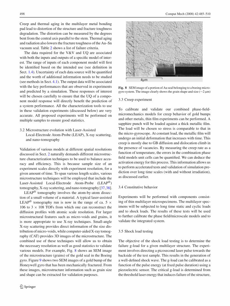
LEAP® tomography involves the atom-by-atom dissec-tion of a small volume of a material. A typical laser-assistedLEAP® tomography run is now in the range of ca. 5 ×10⁶ to 3 × 10⁸ TOFs from which one can reconstruct thediffusion profiles with atomic scale resolution. For largermicrostructural features such as micro-voids and grains, itis more appropriate to use X-ray techniques. Small-angleX-ray scattering provides direct information of the size dis-tribution of micro-voids, while computer-aided X-ray tomog-raphy (CAT) provides 3D images of the microstructure. Thecombined use of these techniques will allow us to obtainthe necessary resolution as well as good statistics to validatevarious models. For example, Fig. 8 shows an SEM imageof the microstructure (grains) of the gold seal in the Boeinggyro. Figure 9 shows two SEM images of a gold bump of theHoneywell gyro that has been mechanically fractured. Fromthese images, microstructure information such as grain sizeand shape can be extracted for validation purposes.
Fig. 8 SEM image of a portion of Au seal belonging to a boeing micro-gyro system. The image clearly shows the grain shape and size (∼2µm)
3.3 Creep experiment
To calibrate and validate our combined phase-field-micromechanics models for creep behavior of gold bumpsand other metals, thin film experiments can be performed. Asapphire punch will be loaded against a thick metallic film.The load will be chosen so stress is comparable to that inthe micro-gyroscope. At constant load, the metallic film willundergo an initial deformation that increases with time. Thiscreep is mostly due to GB diffusion and dislocation climb inthe presence of vacancies. By measuring the creep rate as afunction of temperature, the errors in the combination phasefield models unit cells can be quantified. We can deduce theactivation energy for this process. This information allows usto perform accelerated tests and validation of simulation pre-diction over long time scales (with and without irradiation),as discussed earlier.
3.4 Constitutive behavior
Experiments will be performed with components consist-ing of thin multilayer microspecimens. The multilayer spec-imens will be subjected to long time static and cyclic loadsand to shock loads. The results of these tests will be usedto further calibrate the phase field/microscale models and tovalidate the integrated system.
3.5 Shock load testing
The objective of the shock load testing is to determine thefailure g-load for a given multilayer structure. The experi-ment involves directing a picosecond laser pulse towards thebackside of the test sample. This results in the generation ofa well-defined shock wave. The g-load can be calibrated as afunction of the pulse energy (at fixed pulse duration) using apiezoelectric sensor. The critical g-load is determined fromthe threshold laser energy that induces failure of the structure,
123

Comput Mech (2008) 42:485–510 499
Fig. 9 SEM images of a goldbump within a Honeywellmicro-gyro system. a The entiregold bump after it has beenmechanically fractured. b Thefracture surface showing ductilefailure characteristics
as noted from cracking of the substrate or coating delam-ination. These experiments will be performed on multiplesamples to obtain a meaningful Weibull plot to assess thestatistical variation of the failure g-load.
4 Verification, validation, and uncertaintyquantification (V&V And UQ)
4.1 V&V and UQ methodology
4.1.1 Verification methodology
The starting point in our verification process for existingcodes will be a thorough review of the previous verificationactivities for single codes. The code verification portion forassessing coding errors (source 1), will rely on benchmarksolutions, to include analytical solutions and the develop-ment of manufactured solutions. The calculation verificationportion for assessing numerical error (source 2) will rely ona posteriori error estimation techniques such as error esti-mators for finite element solutions by Zienkiewicz and Zhu[39] and Richardson Extrapolation [39,40] and possibly toestimate approximation and truncation errors. These meth-ods will be carefully coordinated with adaptive methods formesh discretization control [41,42].
For combined/coupled code calculation verification, it issuggested that new calculation verification methods, suchas pointwise error estimation, be explored. In addition tothe adaptive control of discretization errors, methods for thecontrol of modeling and scale linking errors are under devel-opment. In those situations when there is a well qualifiedmathematical model hierarchy it is possible to effectivelybuild off the methods developed for mesh discretization errors[43] to develop an adaptive control method. In other cases,methods based on physical hierarchy can be used [44].
4.1.2 Validation methodology
To address the three key aspects of model validation (seeSect. 1.4), we will use statistical model calibration [45] as
a core capability in our model validation methodology. Thiswill help to construct probabilistic models that are quantifi-ably close to experimental evidence. The validation metrics[46] will wrap probabilistic measures around these physi-cal quantities in order to enable the comparison of scatter inpredictions with scatter in experimental evidence throughstatistical hypothesis testing. Of importance is the metricthat can measure the global predictive capability of a modelover a specified domain of interest as well as the metric forassessing the confidence of using the predictive model foran intended application. As an extension of model valida-tion, the topic of model updating will be pursued. This willinclude bias correction, conditioning, and sensitivities withrespect to experimental errors, sampling errors, and modelingerrors [45,47–50]. A probabilistic procedure for multiscalevalidation will also be used to complement the above valida-tion methods whereby the probabilistic scatter in the parame-ters estimated from a multiscale data assimilation procedure(Sect. 4.1.3) will serve as an indication of the confidencewith which a particular upscaling procedure can be used. Inaddition, the probabilistic multiscale approach we proposepermits an analysis of the error associated with the choice ofa gradient-based theory in representing the mechanics. Thiscan be easily achieved by computing, over an RVE, higherorder gradients terms and estimating their influence on theperformance metric.
4.1.3 UQ methodology
Two distinct parts to UQ are considered in this work: UR anduncertainty propagation (UP). For UR, all sources of para-metric uncertainty will be represented as stochastic fieldsindexed over space and/or time as appropriate. Karhunen-Loeve expansions of stochastic processes can first beemployed to deduce reduced-order representations in termsof a small denumerable set of random variables. These jointrandom variables can in turn be represented using their PCdecomposition in order to capture their non-Gaussian char-acter [45,51–53]. Using a single term in the Karhunen-Loeveexpansion yields a representation in terms of the most
123

500 Comput Mech (2008) 42:485–510
representative random variable, while including a single termin the PC decomposition yields a Gaussian model. Adaptiverefinements can be pursued by monitoring the convergenceof both of these expansions. We can rely both on asymptoticdistributions and a posteriori distributions [45,54] for gagingthe significance of additional measurements on the predictionconfidence, as these measurements will reduce the varianceof the sampling distribution.
A suite of UP tools that implement stochastic projections(polynomial chaos), importance sampling, Latin hypercube,and Cubature sampling as well as combinations of thesetechniques can be employed. Many of these methods devel-oped have been integrated into high-performance comput-ing platforms, Sundance and DAKOTA at Sandia NationalLaboratory (SNL). The choice of UP method is problemdependent based on factors such as the statistical scatter inthe parameters, and the scale of fluctuation of the solutionin space and time. It is best to select the combination ofthese methods that is best suited to the initial output of thesimulations.
Efficient algorithms for uncertainty propagation need to bedeveloped even with petascale computing. Algorithms thatare both adapted to memory-bound or CPU-bound computa-tions can be employed, thus providing options for integrationinto the petascale computational model as it evolves. Thesealgorithms will essentially rely on conditioning by the meanmodel or an approximation thereof. Moreover, orders of mag-nitude efficiencies will be gained by relying on reduced ordermodels to reduce the stochastic representation of our solu-tion [54,55]. The UP and UR methods described above areideally adapted to the present multiscale problem, in par-ticular to the two issues of multiscale data assimilation andupscaling.
Multiscale data assimilation. From a set of experimen-tal observations at a coarse scale, the initial conditions forsimulations at a finer scale will be computed as stochasticprocesses. This procedure can be applied for assimilationbetween any scale at which observations are available andthe next finer scale. This can be carried out using two proce-dures: (1) Multiscale Ensemble Kalman filter procedure [56]and (2) Bayesian assimilation procedure [45]. These methodscan be adapted to the probabilistic multiresolution continuumtheory described in Sect. 2.2.3.
Methods for stochastic upscaling will be used that permitthe monitoring of the error incurred in this process. AdvancedUP methods will be coupled with the multiresolution contin-uum theory to predict the failure of heterogeneous materialsdirectly in terms of the microstructural evolution at multi-ple scales considering the random initial microstructure andother sources of uncertainties.
Managing computational complexity of UQ. It is impor-tant to recognize the added computational burden that anyUQ and V&V methodology will impose on a multiscale
model-based prediction, and the wealth of opportunities toexplore efficient algorithms on the UQ side of the compu-tations. In order to keep pace with the flow of experimentalmeasurements, we will use a mixture of models to repre-sent uncertainties. Specifically, in the early stages, an inter-val model will be used to characterize those uncertaintiesobtained from an inverse analysis associated with experi-mental measurements (e.g., modal characteristics), while aprobabilistic model with a non-parametric distribution willbe used for the constitutive properties synthesized from sub-scale simulations. By treating interval variables as randomvariables whose distribution is an indicator function, we willbe able to maintain consistency in the treatment of uncer-tainty across all aspects of the problem. For subsequent years,the output from the interval-based analysis will serve toconstruct a prior probability measure which will be used inconjunction with a Bayesian procedure to update the proba-bilistic models for both material parameters and experimentalobservations.
4.1.4 Optimal decision making under uncertainty
It is important to prioritize validation and UQ tasks, anddata collection activities. Our proposed UQ methodologyfacilitate for V&V by enabling the analysis of the effectof the various uncertainties based on statistical sensitivityanalysis [57–59] and provide means to mitigate them. Finiteresources in validation, including experimental data quantityand quality, schedule constraints, and computational limita-tions, make the design of validation procedure a very difficultoptimization under uncertainty problem. The objective is toseek sequential physical and computer experiment designs[45,60] in terms of budgeted experimental resource (e.g.,amounts of experimental data, cost of one single experiment)that maximize the utility function of a validation process con-sidering various sources of uncertainties. The research hereis to study how such utility function should be constructedto reflect the potential constraints on experiments and thevalue of improved model accuracy. Using optimal decisionmaking, the obtained model errors with UQs can be used todetermine the optimal combination of high and low-fidelitymodels in simulation.
4.2 An illustration of the proposed V&V and UQ strategy:multiscale modeling of creep
Here we illustrate our V&V strategy for the creep model.The uncertainties associated with the modeling, simulationand validation experiments for creep are shown in Fig. 10.In the coupled DFT-KMC-phase field model, each modelwill be validated independently against existing experimentaldata, and then the coupled model will be validated againstexperiments conducted in this program.
123

Comput Mech (2008) 42:485–510 501
Fig. 10 Uncertainties in creepexperiment and modeling
Uncertainties in experiment: Experiment setup variation; Measurement error; Sample variability
Uncertainties in simulation: Discretizationerror; Parameter uncertainty; Simulation domain size; Boundary Conditions; Uncertainty of initial microstructure representation
DFT
Atomic diffusion /
creep experiment
3D atom probe/X-ray
Scattering/tomography
KMC
Creep Simulation
Input for ValidationTemperature,
loading (creep), initial microstructure
descriptor
Phase field model
Lower scale inputs from experiments
or
Experiment
Output for ValidationMicrostructure descriptor
statistics(e.g., Grain aspect ratio)Displacement time curve
(creep)
We can validate the accuracy of VASP by comparingagainst existing experimental data such as compound for-mation energies, diffusion constants, and phase diagrams.This can capture the physical modeling error (source 3 inSect. 1.4); there are also approximation errors (source 2)associated with the choice of convergence criteria, energycutoff, k-point sampling, which can be controlled and esti-mated through verification. The energetics in the off-latticeKMC method can be given by interatomic potentials fittedfrom many unit cell DFT calculations, which again intro-duces modeling error (source 3). Third, the particular form(source 3) of the phase field model is next formulated basedon the phenomena observed in the KMC calculations. Theparameters in the chosen model are fitted to the interfacialwidth and interdiffusion rates, for instance, from the KMCresults. The validation of physical results generated fromKMC and phase field model involves the same experimentalmeasurements (i.e., interfacial structures and widths, ratesof interdiffusion, and morphological evolution of the inter-faces); however, the imaging needs to have the necessaryresolutions to validate each because one is atomistic in resolu-tion while the other is at nanoscale in resolution. In validatingthe multiscale (DFT + KMC + PF) model of Coble creep dueto GB diffusion, we can compare two output measures of 1)the grain aspect ratio and 2) the displacement time curve forinput measures of temperature, load, and initial microstruc-ture. The variability in test samples can have a major effecton the result, and the scatter in creep experiment is about1–5%. All proposed experiments will be performed onenough samples to ensure accurate statistics.
Some of these experiments can be used to calibrate thediffusivities of grain boundaries, while the remaining experi-ments can be used to validate the predictions obtained throughKMC and phase field simulations. The experimental obser-vations can serve directly (without any inverse analysis) toconstruct a time-varying stochastic process model for the
diffusivities which can then be used in KMC simulationsto propagate the corresponding uncertainty to phase fieldmodel input parameters. It can be assumed that the randomdiffusivities are statistically independent of the initial andboundary conditions at the atomic scale. These initial andboundary conditions can be assumed to be homogeneouslyrandom with very short correlation length, thus justifying theanalysis over a typical (random set) of initial and boundaryconditions.
5 Code components of the integrated software system
The final multiscale integrated materials simulation systemwill consist of the software listed in Fig. 4. For example,we will build the petascale software system by linking sev-eral codes from the Tri-Labs and Northwestern Universityto Sandia’s TAHOE code, which will be linked to Sandia’sDAKOTA (a V&V and UQ code) and LAMMPS (an MDcode) in the final simulation system after new capabilities forsolving the overarching problem are added. A brief descrip-tion of the various codes is given in the following.
TAHOE is a research-oriented platform for the develop-ment of numerical methods and material models and wasdeveloped for the simulation of material response under con-ditions that cannot be treated by standard continuum simu-lation techniques. These situations include coupled-physicsphenomena, fracture, and deformation in small-scale struc-tures.
LAMMPS is a molecular dynamics code that can modelensembles of particles in liquid, solid, or gaseous states. Itis capable of simulating atomic systems using a variety offorce fields and boundary conditions. LAMMPS runs effi-ciently on massively parallel computers, and can effectivelymodel systems with up to billions of particles. LAMMPS hasbeen benchmarked on ASCI Red, an Intel-based Tflop MPP
123

502 Comput Mech (2008) 42:485–510
of about 9k processors, Red Storm, a Cray XT-3 with 10368processors, and IBM Blue Gene/L to 64k processors provid-ing promising scalability a peak of 4.34Tflop performancefor a 40 billion atom calculation.
Design analysis kit for optimization and terascale applica-tions (DAKOTA) will provide the overall framework for theV&V and UQ activities of this project. DAKOTA containsalgorithms for optimization; UQ with sampling/reliability/stochastic finite element methods; parameter estimation withnonlinear least squares methods; sensitivity/variance analy-sis with design of experiments and parameter study capabil-ities; surrogate modeling, etc. As an open software toolkit,DAKOTA provides a flexible and extensible problem-solvingenvironment as well as a platform for research of advancedsolution methodologies.
6 Integrated software system and petascale computing
The various computer codes will be integrated into an effec-tive component-based system operating at the petascale.There will be three clusters of software:
1. TAHOE, the continuum code which will be used to modelthe micro and macro mechanics and the phase field evo-lution (the latter capability is to be added)
2. LAMMPS, the molecular dynamics code, which is to beaugmented by the kinetic Monte Carlo method (KMC)
3. DAKOTA, the V&V and uncertainty quantification pro-gram
We will employ a component-based software strategy inwhich functional interfaces support the interactions betweenprocedures that are used to solve the individual models. Wehave extensive experience with this approach in high-levelapplications, such as the workflow modeling capabilities ofthe SciDAC Scientific Data Management Center for EnablingTechnologies [61] and UQ capabilities of the DAKOTAtoolkit [62], both will play an important role in this project.Component-based software architecture are also being usedto develop the mesh-based simulation procedures in theITAPS SciDAC center [63] and commercially by Simmetrix[64,65]. These efforts include the parallelization of theprocesses using MPI-based distribute memory methods inthe development of parallel adaptive finite element codes[63,66].
Over the past several years we have been applying thisapproach in the development of multiscale simulation pro-cedures. Building on an abstraction of the functional layersand information transformations and transfer between lay-ers in multiscale simulations [67], component-based proce-dures have been constructed for both hierarchical [68] andconcurrent [69] parallel adaptive procedures. LAMMPS is
the MD component in the concurrent multiprocessor con-tinuum/atomistic code developed [69]. This and similarlydeveloped capability can be used to support the interactionsbetween existing software components used in this project.
6.1 Scalability and parallel performance
Many factors must be addressed in the development of a scal-able adaptive multiscale simulation for 100,000+ processors.These include:
• Ensuring that there are enough concurrent calculations ina given step (i.e., a given set of models and discretiza-tions).
• Implement sufficient control of the communications toachieve scalability.
• Provide a set of structures and algorithms to provide adap-tive control for a scalable execution of the multiscale sim-ulation.
• Dynamically load balance the calculations for the eachstep in a scalable manner.
Based on the sizes of models described previously, the pro-posed simulations will require petascale computing. The firstquestion to be addressed is whether the single scale analy-sis tools can scale to petascale. The LAMMPS moleculardynamics code has already shown acceptable performanceon the LLNL Blue Gene/L system [70] and is expected toextend to the petascale machines for large enough atom-istic systems. For continuum simulations we will build onTAHOE which has been parallelized using the Aztec [71]and SPOOLES [72] solvers and can be effectively integratedwith other parallel solver technologies (e.g., PETSc [73] andTrilinos [74]). Efforts will be required to scale TAHOE topetascale class machines and to effectively support paralleladaptive methods. This effort will rely heavily on a combi-nation of mesh partition and matrix free solution techniques.We have recently performed scaling tests of an RPI internalunstructured finite element code on IBM Blue Gene/L’s atIBM and Rensselaer. In one test on a 5 million vertex mesh,doubling the number of processors form 512 to 8,192 proces-sors maintained a 95% scaling on the fixed mesh. A secondtest on an 18.5 million vertex problem showed a 99% scal-ing in going form 1,024 to 16,384 processors [66]. Thosetechnologies will be brought into TAHOE.
Central to the parallel multiscale analysis is controllingload distribution and interprocessor communications for theheterogeneous computations performed. Since it is desirablethat the computations be adaptively executed, computationalload balancing must be dynamically applied as the computa-tion executes. Sandia’s Zoltan software [75,76], which sup-ports load balancing of general objects with both computationand communication weights, represents a starting point for
123

Comput Mech (2008) 42:485–510 503
Fig. 11 Parallel adaptive mesh example (colors correspond to processors)
this need. We already have experience on the development ofparallel adaptive simulations [63,66,77,78] (see example inFig. 11), and have begun applying those methods to paralleladaptive multiscale analyses [68,69]. Among the extensionsto current methods that are needed for parallel multiscalecodes are multilevel dynamic load balancing. For example,we will need one level of dynamic load balancing to dealwith the large set of unit cell models on the microscale and asecond to deal with the adaptive control of the coarsest scalemodel.
6.2 Implementation plan for multiscale simulationand uncertainty quantification
As indicated above, we will take extensive advantage of soft-ware and methods that have been developed by DOE and theiruniversity partners. In several cases, we will use this softwarewithout modification, in others we will work closely withthe developers to perform extensions such that their toolscan operate effectively as a component (e.g., the LAMMPSexample above) or to add a needed feature. One code forwhich more extensive developments are needed is TAHOEwhich will be the central tool for the multiscale simulations.
To gain an appreciation for the process of performing aterascale multiscale simulation and the types of capabilitiesto be integrated into TAHOE, we consider the shock loadingof the disk of a micro-gyro. The next paragraph defines theproblem and the paragraph after that considers it parallelsolution on petascale computers.
In the petascale simulation of the coupled macro–microcontinuum model, the macro model will be discretized intoan adaptively refined mesh of order 107 elements. In the hier-archical multiscale model, the microscale model is linked atselected points in the critical portions of the macro model.For the current discussion assume there are 5,000 such loca-tions. Let’s further assume that at these locations the influenceof nano voids is important. Thus the micro-model unit cellmay have a mesh of 100,000 elements. (Note that when UQand other statistical aspects are included, there will need tobe more unit cells considered.) Assume the unit cells prob-lems are solved using an explicit method and that 100 time
steps are needed on the microscale for each macroscale timestep.
The most obvious approach to the scaleable solution ofthis problem on a petascale parallel computer requires theability to do an implicit solve on the macro mesh using thescalable solvers discussed above. In addition, the system(i.e., the mesh and equations) must be constructed in par-allel. Since the formation of the system contributions for amacro-element with a microscale material point model mayrequire the solution of 100 time steps of a 100,000 elementmesh, it is not reasonable to use a single level load balancingprocess. In this case, a two level method would be suitable:elements that require material point model solves (i.e., hotspots) would be distributed over multiple processors whilegroups of standard macro elements are constructed on otherprocessors.
Algorithms that operate in parallel over distributed mesheswill be developed to determine the workloads and to constructthe appropriate communication graphs for parallel load bal-ancing using instances of Zoltan [75]. Since these proceduresmust operate in parallel on distributed structures, they canbe used to support adaptive processes where the workloaddistribution changes as simulations proceed. Note that thegeneral methodology of constructing levels of parallel com-putations and distributing them can be applied to the othermultiscale couplings of interest here, including concurrentmethods, coupled atomistic-continuum models, time scalelinking, various methods of adaptive model and discretiza-tion (mesh) control, etc. We plan to generalize the implemen-tation of these approaches.
Massively parallel computers that can deliver a sustainedpetaflop computation are estimated to have around 500,000processing cores. Therefore it is critical to account for thefact that cores or nodes can fail during a multiscale simu-lation. A standard approach to deal with this is file-basedcheck pointing for restarts. With this many processors, thisis unlikely to be an effective approach.
Since it is possible to recover one step in the simulationby the storage of a small fraction of the total data, a feasiblestrategy may be the following. Each processing node is pairedwith a neighboring node. These two nodes maintain a copyof the restart information for each other while maintaining
123

504 Comput Mech (2008) 42:485–510
their own data. In addition, for a larger grouping of nodes,a few nodes are reserved to replace any node that is lost. Inthis model the system can continue to recover as long as bothmembers of a node pair do not fail on the same step.
Since much of the proposed UQ effort will evolve aroundDAKOTA, the parallelization task is simplified usingDAKOTA’s advanced functionality for multilevel paralle-lism. We will use DAKOTA as a wrapper and function-call-manager, for carrying-out the stochastic projection approach[51] to UQ and propagation. This approach essentially entailscomputing the PC approximations to the solution using a sto-chastic Galerkin projection.
7 Novel microsystem materials design
Materials design activities which synergistically exploit thedeveloping modeling capabilities of the parallel researchthrusts will address enhanced materials stability for compo-nent reliability in both existing sensor and future actuationmicrosystems. In line with the longer-term nature of newmaterial design, the examples will emphasize high powerdensity microactuation materials of interest for stable oper-ation in laser micromirror systems.
7.1 Actuation materials
An important component of aerospace microsystems is theactuation materials that can enable reliable high power den-sity mechanical devices. A potential high-impact exampleof the latter, of particular interest to Boeing, is the use ofhigh displacement actuation materials for precise control oflaser micromirror systems. Shape memory alloys activatedby resistive heating have been identified as offering uniquepotential for desired high power density, particularly as theefficient heat transfer in thin-film form allows desired highfrequency of operation. TiNi-based shape memory alloyshave been proposed as particularly suitable for radiationenvironments. Current commercial shape memory alloys,however, suffer from limited cyclic life. This limitationhas been addressed in the recent computational design ofnanodispersion-strengthened shape memory alloys demon-strating greatly improved parent-phase strength to enableboth higher output force and enhanced cyclic life throughelimination of accommodation slip during martensitic trans-formation. Preliminary prototype alloy evaluation indicatesthat optimization of nanodispersion particle size can providea predictable stored elastic energy effect on phase stabilitywithout increasing transformation hysteresis. The problemof detailed optimization of the particle dispersion interac-tion with martensitic transformation is well suited to ourmicrostructural simulation tools. The productive integrationof these novel materials into aerospace microsystems pro-
vides an ideal opportunity to demonstrate the applicationof our full set of predictive-science tools spanning marten-site kinetics, nanoscale precipitation, multiscale mechanicalbehavior, and probabilistic system integration, while incor-porating previously well studied aging effects in shape mem-ory alloy systems. Potentially, we can integrate our multiscalepredictive-science tools in the accelerated reliable engineer-ing of this new class of nanostructured high performanceshape memory alloys for aerospace microsystems, exploit-ing validated predictive-science to accurately forecast theirlong-term evolution in service.
7.2 High Q coatings
Application of predictive-science-based coating design willemphasize conductive coatings on high performance (highQ) quartz resonators for the navigation grade DRG micr-ogyroscopes. The coating material designs will have moreimmediate impact through integration in the microgyroscopesystem development.
High-precision micro-gyroscopes must have largeQ-factors (= resonance frequency/width of the resonance).Finite Q-factors are due to various energy loss mechanisms,such as phonon dissipation, internal friction and electronicexcitations. Previous experiments demonstrated that with theuse of quartz in the micro-resonator, the primary energy lossis due to electronic excitation in the electrical contacts. Con-ceptual designs of conductive coating materials for the quartzresonators can explore both initial performance and the sta-bility of the coating Q to environmental exposure includingradiation. In addition to conventional candidate coating met-als of Al, Pt, and Au, bismuth is also a strong candidate,because its room-temperature electron mobility is 600 timesgreater than that of gold. Potential stability against radiationinduced defects can ultimately be validated by internal fric-tion measurements after radiation exposure.
7.3 Anti-stiction coatings
Stiction is a phenomenon that may occur in micro-systemswith suspended structures. Failure occurs when the stictionforce is strong enough to bring a key structure of the micro-system into contact with the substrate. When the adhesionforce exceeds the elastic restoring force after the contact isestablished, the structure is pinned to the substrate. One solu-tion to this problem is to coat both surfaces (structure ofinterest and the substrate) with a material that exhibits lowadhesion in a normal air or vacuum environment. Concep-tual design activities can explore a range of possible coat-ing strategies to mitigate this failure mode, employing thedeveloping atomistic modeling tools. One candidate mate-rial already identified is sulfur-doped diamond-like carbon(DLC). The mechanism proposed for theoretical evaluation
123

Comput Mech (2008) 42:485–510 505
is that a sulfur-doped DLC surface markedly slows down therate of oxidation, thus maintaining a non-polar surface forextended periods; this in turn suppresses adsorption of watervapor from the ambient and thus capillary/adhesive forcesdue to the presence of adsorbed water. After model-basedtheoretical evaluation of such coating concepts, validationexperiments can use atomic force microscopy (AFM) to mea-sure the adhesion between a silicon tip of known geometryand a flat silicon surface, both coated with the prototype mate-rials. After exposing the two surfaces to air with controlledhumidity, their adhesion can be directly measured using thepull-off technique.
8 Conclusions
We have presented a roadmap for a petascale predictive-science-based verified and validated multiscale modeling andsimulation system to predict the performance and materialsintegrity of microsystems. The development of the predictivesystem consists of integration of the following three thrusts:(1) the modeling of long-term materials instability, aging,and radiation-enhanced microstructure evolution by couplingquantum/atomistic-mechanical, phase field models, micro-mechanics, and multiscale statistical continuum mechanicsmodels; (2) the development of verification, validation, andUQ methodologies and implementation of them on petas-cale platforms; and validation of computational models onmicrosystem components and subsystems including: vacuumseals, resonators and metallic bonding pads; (3) developmentof a petascale software system by a component-based inte-gration approach.
We emphasize that although our focus is on microsystemperformance and reliability prediction, the roadmap shouldbe applicable to developing similar predictive simulationsoftware for other complex systems such as high strengthalloys, energy harvesting systems, or even biological sys-tems, with few modifications.
Appendix
A1. The Boeing disc resonator gyroscope (DRG)
A1.1 Description of the Boeing DRG
The Boeing Disc Resonator Gyroscope (DRG) (US Patents7,040,163 and 7,063,714), exemplary representation of anaerospace micro-gyro system in our focus problem, is a disc-shaped resonator supported on a central silicon stem that isbonded to a silicon substrate (see Fig. A1). The planar discdesign allows modern micromachining techniques to be usedto manufacture this standingwave gyroscope device, in con-
trast to the hemispherical shell design requiring cumbersomeconventional machining. The disc consists of a number of cir-cular concentric rings and interleaved segments connectingthe concentric rings. A number of electrodes can be co-etchedto protrude out from the substrate through the slots betweenthe concentric rings of the disc, to sense or drive mechanicaldisplacement. The disc generally has two in-plane vibrationmodes at resonance and the orientation of the vibration modechanges during rotation of the entire device according to theCoriolis effect. The disc and the electrodes are made of dopedsilicon in typical design, but fused quartz with a thin layer ofconductive thin film can replace silicon as the disc material toobtain better performance as will be described in more depthbelow.
A1.2 Operation principle of the DRG
At resonant frequency (∼20 kHz), the disc resonator has twodegenerate in-plane vibration modes so that the vibration pat-tern depends on the excitation direction. The disc is driven toresonance by the driving electrodes with AC voltage near theresonant frequency. The driving electrostatic forces dependon the sign and amplitude of the charges accumulated at thedriving electrodes and the disc. To sense mechanical motionof the disc, capacitance sensing is used in that the sensingelectrodes and the disc together act as a capacitor. Any changein the gap size between the sensing electrode and the discresults in a change of electric current in the integrated cir-cuit.
The vibration pattern of the gyroscope changes upon rota-tion of the entire microsystem according to the Coriolis effectas shown in Fig. A2. In addition to the centrifugal force act-ing on the disc during rotation, an additional accelerationcalled the Coriolis acceleration acts on the disc if the discis already in vibratory motion before the rotation. The Cori-olis acceleration dominates the centrifugal acceleration forthis device, and it is given by a = −2ω × v where ω is therotation vector and v is the velocity of a point on the disc.Since the velocity at every point on the disc is different, theCoriolis acceleration forces the vibration pattern to change.Therefore, the vibration pattern change can be correlated tothe gyro rotation rate in order to determine the latter in realapplications.
A1.3 Fabrication of the DRG
The micro-gyroscope is made by micromachining two single-crystal silicon wafers, one for the disc and one for the sub-strate with gold wires deposited on it, which are subsequentlybonded together (Fig. A3). A 500 µm thick doped siliconwafer is used for the disc. Multilayer bonding pads are deposi-ted at the electrode and center support sites in the followingorder: a 10 nm thick titanium (Ti) layer, a 20 nm thick
123

506 Comput Mech (2008) 42:485–510
Fig. A1 The Boeing discresonator gyroscope (DRG).a A photo showing the top viewof the disc on a substrate.b A schematic assemblydrawing of the sensor die
Silicon Cap
Electronic ControlUnit
Resonator Disc• P-doped Si or metal
coated fused quartz
Sensing andDrivingElectrodes• P-doped Si
Silicon substrate
Silicon Oxide Layer• Gold Wiring on Top
Au seal
MultilayerBonding Padsat CentralSupport
(a) (b)
Standing wave vibrationpattern: aftercase rotation
Standing wave vibrationpattern: beforecase rotation
90ºcase rotation
36º
Fig. A2 Vibration pattern of the Boeing DRG
platinum (Pt) layer, and a 350 nm thick gold (Au) layer. Onthe other hand, the fabrication process of the Substrate startswith a 500 µm thick doped silicon wafer. The silicon wafer isfirst etched to produce the desired pattern for the center sup-port and the electrodes and then the top surface is oxidizedto produce a 150 nm thick silicon oxide layer that servesas electrical isolation from the doped silicon below. Thebonding pads of identical composition as described aboveare deposited on top of the oxide layer at the electrode andcenter support sites, which are connected by gold wires thatare deposited subsequently on top of the substrate to verticalinterconnect pins on the perimeter to a third, end cap waferwith VLSI gyro control electronics and the gyro externalelectrical connection pads. The disc and substrate wafers arebonded together at the electrode and center support sites byapplying pressure and heat at approximately 400◦C to formsingle-bonded metal joints. Finally, the slots with or withoutthe electrodes inside the slots are formed from the bondedstructure through etching.
1. Begin with a piece of single crystal silicon (500 micron thick)
2. Etch out desired pattern of center support and electrodes
3. Oxidation to obtain a layer of silicon oxide (150 nm)
4. Lay down the bonding pads, each of which consists of a layer of titanium (10 nm), a layer of platinum (20 nm), and a layer of gold (350 nm).
Substrate
Substrate
Substrate
Substrate
Disc
Substrate
Disc
Substrate
Disc
Disc
5. Begin with another piece of doped crystal silicon (500 micron thick)
6. Etch out the desired pattern and lay down the bonding pads, each of which consists of a layer of titanium (10 nm), a layer of platinum (20 nm), and a layer of gold (350 nm)
7. Bond substrate piece and disc piece together.
8. Etch out slots on the disc and electrodes on the subtrate
Fig. A3 Fabrication process of the Boeing DRG
B1. The Honeywell tuning fork gyroscope
B1.1 Description of the Honeywell tuning fork gyroscope
The Honeywell Tuning Fork Gyroscope consists of a p-dopedsilicon structure that is attached to a lower glass substrate withgold layering deposited on it, as represented by the generictuning fork design in Fig. B1. The silicon structure consistsof two proof masses supported by a pair of trusses that areanchored to the glass substrate. During operation of the gyro,the proof masses are driven electrostatically at the comb teethedge by an outer motor drive and vibrate in-plane and anti-phase to each other. If a rotation is applied about the horizon-tal axis perpendicular to the velocity vector of the masses,one proof mass would rise and the other would sink due to theCoriolis Effect, as schematically illustrated in Fig. B2. Themotion of each proof mass is sensed by a capacitor, whichis made from the bottom side of the proof mass, and a goldlayer deposited onto the associated glass substrate below theproof mass.
123

Comput Mech (2008) 42:485–510 507
Fig. B1 Tuning forkgyroscope. a Entire device withproof masses on either side ofthe central axis. b The combteeth between proof masses andthe central axis
Fig. B2 Operating principle of the Tuning Fork Gyro similar to Hon-eywell design. It is based on the Coriolis acceleration, a = −2ω × vwhere ω is the rotation vector and v is the velocity of a material pointon the proof mass. a Top view, b front view
B1.2 Fabrication of the Honeywell tuning fork gyroscope
The sensor is manufactured by the process as shown inFig. B3. First, highly p-doped epi silicon is CVD grown ontop of a lightly p-doped substrate. In the final sensor struc-ture, all the lightly doped portions are etched away. On theother hand, the glass substrate is micro-machined separately,then bonded to the silicon. A mesa channel, which forms thesense gap underneath the proofmass, as well as interconnectpatterns are etched and deposited onto the glass substrate.The final patterned glass substrate is anodically bonded tothe silicon substrate by applying a combination of heat, pres-sure, and electrostatic field to form strong chemical bonds
Lightly p-doped
Glass substrate
Gold capacitor plate
2. DRIE (Deep Reactive Ion Etching) etch to define silicon pattern
3. Pattern and etch the bottom glass substrate. Deposit gold layering
Doped silicon substrate
Glass substrate
Glass substrate
proof mass
4. Bond silicon and bottom glass substrate and
5. Etch away all the lightly doped silicon, leaving the patterned highly doped epitaxial silicon layer
Highly p-doped
proof mass
1. Highly doped epitaxial silicon is grown on top of lightly doped silicon substrate.
Fig. B3 Fabrication process of the Honeywell gyro
between silicon atoms of the wafer and oxygen atoms in theglass.
As shown in Fig. B3, starting with a lightly p-doped siliconsubstrate, a highly p-doped epitaxial silicon layer is grownon the substrate. A layer of photosensitive film is depositedon top of the highly p-doped silicon layer, which is thenpatterned with a mask with the desired features. The siliconsubstrate is then exposed. Deep Reactive Ion Etching (DRIE)is used to etch the silicon pattern on the highly p-doped siliconlayer, such as the mechanical, electromechancial members ofthe device and proof masses. Finally, the remaining portionof the photosensitive film is removed to give the final patternof highly p-doped silicon layer on lightly p-doped siliconsubstrate.
On the other hand, a glass substrate is used as a bottom sup-port. First, the substrate is etched to have the desired pattern.A photosensitive film is placed on the surface of the glass sub-strate and then is partially covered by mask with the desiredpattern for the features. Exposing it in the light, the photo-sensitive layer is then removed with the developer solution.The portion of the support substrate that is not covered bythe mask is etched till the mesas are formed with the desiredheight. Then another layer of photosensitive film is placed ontop of each substrate and is then covered with another maskwith the desired metallization pattern. Exposing the supportsubstrate in the light again and etching the portion without
123

508 Comput Mech (2008) 42:485–510
Table C1 Performance requirements for different classes of gyro-scopes [79]
Parameter Rate Tactical Navigationgrade grade grade
Bias drift (◦/h) 10–100 0.1–10 <0.01
Angle random walk (ARW), ◦/√
h >0.5 0.5–0.005 <0.001
Full scale range (◦/s) 50–1,000 >500 >400
Max. shock in 1 ms, g’s 103 103–104 103
Power (Watts) 2 – 0.005
Volume (cm3) 10 – 1
the mask allows the recesses for the electrodes to be formed.Next, the metallic materials are deposited to the surface toform the electrodes. Thereafter, the remaining photosensitivefilm is removed to form the final patterns of the upper and bot-tom support substrate. After the patterned silicon substrateand support substrates are ready, the surface of p-doped layeris placed in direct contact with the bottom support substrate.Anodic bonds are then formed between the silicon substrateand the bottom support substrate. The lightly p-doped siliconsubstrate is then removed by etching.
C1.3 Gyroscope design criteria
The design criteria for a gyroscope are listed in Table C1for three different grades of gyroscopes. The applications foreach grade of gyroscope are as follows:
• Rate grade: Video camera stabilization, smart braking,pointers, controls for paralyzed patients, active suspen-sion, and automobile applications (i.e., augmented yawstability).
• Tactical grade: Attitude control of flying objects, machinecontrol and robotics, and surgical instruments.
• Navigation grade: Aerospace applications (i.e., satelliteattitude control and stabilization), naval, and militaryapplications.
The parameters in Table 2 are briefly described in the fol-lowing. Bias drift is the deviation over time due to thermaland electronic noise. Angle random walk (ARW) describesthe average deviation that occurs when the rate signal of thesensor is integrated over time. Full scale range is the rate atwhich the device can measure, and the last criterion is themaximum shock the device can sustain without failing in1 ms. The quality factor Q is a measure of the mechanicalenergy loss, and so the higher the energy loss, the lower thequality factor Q and the higher the ARW and bias drift are.Higher Q also means lower power consumption for the devicesince the gyroscope does not need to be driven as often.
References
1. RF MEMS market 2004–2009 by Wicht Techonologie Consulting,October 2005
2. Micro power sources: opportunities from fuel cells and batteries formobile applications by NanoMarkets. http://www.nanomarkets.net, September 2005
3. MEMS microphones and micro-speakers market. Workshop byWicht Technologie Consulting (2006)
4. Microelectromechanical Systems Technology: Current and FutureMarkets by Andrew McWilliams, February 2006
5. Chicago Tribune on July 6, 20066. abcnews.com on September 6, 20067. Mechanical Engineering, April 20068. Liu WK, Karpov EG, Park HS (2005) Nano-mechanics and materi-
als: theory, multiscale methods and applications. Wiley, New York9. Mao Z, Sudbrack CK, Yoon KE, Martin G, Seidman
DN (2007) The mechanism of morphogenesis in a phase separatingconcentrated multi-component alloy. Nat Mater 6:210–216
10. Vaithynanathan V, Wolverton C, Chen LQ (2002) Multiscale mod-eling of precipitate microstructure evolution. Phys Rev Lett88:125503
11. Wolverton C, Zunger A (1995) Ising-like description of struc-turally relaxed ordered and disordered alloys. Phys Rev Lett75:3162
12. Sizmann R (1978) The effect of radiation upon diffusion in metals.J Nucl Mater 69–70:386–412
13. Wimmer E, Krakauer H, Weinert M, Freeman AJ (1981) Full-potential self-consistent linearized-augmented-plane-wave methodfor calculating the electronic-structure of molecules and surfaces—O2 molecule. Phys Rev B 24:864–875
14. Rittner JD, Seidman DN (1996) Limitations of the structural unitmodel. In: Materials Science Forum, pp 207–209
15. Mantina M, Wang Y, Arroyave R, Wolverton C, Chen L-Q, Liu Z-K (2007) First-principles calculation of self-diffusion coefficients.Phys Rev Lett (submitted)
16. Wilson JR, Kobsiriphat W, Mendoza R, Chen HY, Hiller JM,Miller DJ, Thornton K, Voorhees PW, Adler SB, Barnett SA(2006) Three-dimensional reconstruction of a solid-oxide fuel-cellanode. Nat Mater 5:541–544
17. Eggleston J, Voorhees PW (2002) Ordered growth of nanocrystalsvia a morphological instability. Appl Phys Lett 80:306–308
18. Seidman DN, Averback RS, Benedek R (1987) Displacement cas-cades: dynamics and atomic structure. Phys Stat Sol (b) 144:85
19. Bammann DJ, Chiesa ML, Horstemeyer MF, Weingarten LI (1993)Failure in ductile materials using finite element methods. In: JonesN, Weirzbicki T (eds) Structural crashworthness and failure. Else-vier, Amsterdam, p 1
20. Bammann DJ, Chiesa ML, Johnson GC (1996) Modeling largedeformation and failure in manufacturing processes. In: Tatsumi,Wannabe, Kambe (eds) Theor. app. mech. Elsevier, Amsterdam,p 259
21. Hill R (1963) Elastic properties of reinforced solids: some theoret-ical principles. J Mech Phys Solids 11:357–372
22. Bazant ZP, Belytschko T (1987) Strain-softening continuum dam-age: localization and size effect. In: Constitutive laws of engineer-ing materials: theory and applications, pp 11–33
23. Fleck NA, Hutchinson JW (1993) A phenomenological theoryfor strain gradient effects in plasticity. J Mech Phys Solids41(12):1825–1857
24. In Newscientist.com news, May 19, 200525. Liu WK, Karpov EG, Park HS (2005) Nano-mechanics and
materials: theory, multiscale methods and applications. Wiley,New York
26. Hao S, Liu WK, Moran B, Vernerey F, Olson GB (2004) Multi-scale constitutive model and computational framework for the
123

Comput Mech (2008) 42:485–510 509
design of ultra-high strength, high-toughness steels. Comput Meth-ods Appl Mech Eng 193:1865
27. McVeigh C, Vernerey F, Liu WK, BrinsonLC (2006) Multiresolution analysis for material design. ComputMethods Appl Mech Eng 195(37–40):5053–5076
28. Vernerey F, Liu WK, Moran B (2007) A micromorphic model forthe multiple scale failure of heterogeneous materials. J Mech PhysSolids (under revision)
29. Zhang X, Mehraeen S, Chen JS, Ghoniem N (2006) Multiscaletotal Lagrangian formulation for modeling dislocation-inducedplastic deformation in polycrystalline materials. Int J Multisc Com-put Eng 4:29–46
30. Chen JS, Mehraeen S (2005) Multi-scale modeling of heteroge-neous materials with fixed and evolving microstructures. ModelSimul Mater Sci Eng 13:95–121
31. Chen JS, Mehraeen S (2004) Variationally consistent multi-scalemodeling and homogenization of stressed grain growth. ComputMethods Appl Mech Eng 193:1825–1848
32. Chen JS, Kotta V, Lu H, Wang D, Moldovan D, Wolf D (2004) Avariational formulation and a double-grid method for meso-scalemodeling of stressed grain growth in polycrystalline materials.Comput Methods Appl Mech Eng 193:1277–1303
33. Lee TY, Chen JS (2006) Modeling of grain growth using Voronoidiscretization and natural neighbour interpolants. Int J ComputMethods Eng Sci Mech 7:475–484
34. Shi J, Ghanem R (2006) A stochastic nonlocal model for materialswith multiscale behavior. Int J Multisc Comput Eng 4(4):501–519
35. Gel’fand IM, Vilenkin NYa (1964) Generalized function, vol 4.Academic Press, New York
36. Shi J (2003) Stochastic modeling of materials with complexmicrostructure. PhD thesis, Johns Hopkins University
37. Seidman DN (1973) The direct observation of point defects in irra-diated or quenched metals by quantitative field-ion microscopy.J Phys F Metal Phys 3:393–421
38. Seidman DN (2007) Three-dimensional atom-probe tomography:advances and applications. Annu Rev Mater Res 37:127
39. Richards SA (1997) Completed Richardson extrapolation in spaceand time. Commun Numer Methods Eng 13:558–73
40. Roache PJ (1998) Verification and validation in computational sci-ence and engineering. Hermosa Publishers, Albuquerque
41. Ainsworth M, Oden JT (1997) A posteriori error estimation in finiteelement analysis. Comput Methods Appl Mech Engrg 142:1–88
42. Babuska I, Strouboulis T (2001) The reliability of the FE method.Oxford Press, New York
43. Oden JT, Babuska I, Nobile F, Feng Y, Tempone T (2005) Theoryand methology for estimation and control of errors due to modeling,approximation and uncertainty. Comput Methods Appl Mech Eng194:195–204
44. Nuggehally MA, Picu CR, Shephard MS, Fish J (2007) Adap-tive model selection procedure for concurrent multiscale problems.J Multisc Comput Eng (to appear)
45. Ghanem R, Doostan A (2006) On the construction and analysis ofstochastic predictive models: Characterization and propagation ofthe errors associated with limited data. J Comput Phys 217(1):63–81
46. Oberkampf W, Barone M (2004) Measures of agreement betweencomputation and experiment: validation metrics. In: 34th AIAAfluid dynamics conference and exhibit, AIAA-2004-2626, Port-land, Oregon, June 28–1
47. Romero V (2007) Validated model? Not so fast—the need formodel “Conditioning” as an essential addendum to model vali-dation. In: 48th AIAA/ASME/ASCE/AHS/ASC structures, struc-tural dynamics, and materials conference, Honolulu, Hawaii, April23–26
48. Kennedy MC, O’Hagan A (2001) Bayesian calibration of com-puter experiments. J R Stat Soc B 63:425–464
49. Chen W, Xiong Y, Tsui K-L, Wang S (2006) Some metrics and aBayesian procedure for validating predictive models in engineer-ing design. In: ASME design technical conference, design automa-tion conference, Philadelphia, PA, September 10–13 (accepted byJ Mech Des)
50. Mahadevan S, Rebba R (2005) Model predictive capability assess-ment under uncertainty. In: 46th AIAA/ASME/ASCE/AHS/ASCstructures, structural dynamics and materials conference, Austin,Texas, April 18–21
51. Ghanem RG, Spanos PD (1991) Stochastic finite elements: a spec-tral approach. Springer, New York
52. Descelliers C, Soize C, Ghanem R (2006) Maximum likelihoodestimation of stochastic chaos representation from experimentaldata. Int J Numer Methods Eng 66(6):978–1001
53. Descelliers C, Soize C, Ghanem R (2007) Identification of chaosrepresentations of elastic properties of random media using exper-imental vibration tests. Comput Mech 39(6):831–838
54. Doostan A, Ghanem R, Red-Horse J (2007) Stochastic modelreduction for chaos representations. Comput Methods Appl MechEng 196:3951–3966
55. Ghanem R, Saad G, Doostan A (2007) Efficient solution of sto-chastic systems: application to the embankment dam problem.Struct Saf 29(3):238–251
56. Zou Y, Ghanem R (2004) Multiscale data assimilation with theensemble kalman filter. SIAM J Multisc Model 3(1):131–150
57. Liu H, Chen W, Sudjianto A (2006) Relative entropy based methodfor global and regional sensitivity analysis in probabilistic design.ASME J Mech Des 128(2):1–11
58. Chen W, Jin R, Sudjianto A (2005) Analytical variance-basedglobal sensitivity analysis in simulation-based design under uncer-tainty. ASME J Mech Des 127(5):875–886
59. Yin X, Chen W (2007) A hierarchical statistical sensitivity analy-sis nethod for complex engineering systems, DETC2007-35528.In: 2007 ASME design technical conference, design automationconference, September 4–7, Las Vegas, NV
60. Giunta AA, Swiler LP, Brown SL, Eldred MS, Richards MD, CyrEC (2006) The surfpack software library for surrogate modelingof sparse irregularly spaced multidimensional data, paper AIAA-2006-7049. In: Proceedings of the 11th AIAA/ISSMO multidis-ciplinary analysis and optimization conference, Portsmouth, VA,September 6–8
61. http://www.scidac.gov/viz/SDM.html, The Scientific Data Man-agement Center for Enabling Technologies SciDAC Center
62. http://www.cs.sandia.gov/DAKOTA/software.html63. Chand KK, Diachin LF, Li X, Ollivier-Gooch C, Seol ES, Shep-
hard MS, Tautges R, Trease H (2006) Toward interoperable mesh,geometry and field components for PDE simulation development.Eng Comput (to appear)
64. Beall MW, Walsh J, Shephard MS (2004) A comparison of tech-niques for geometry access related to mesh generation. Eng Com-put 20(3):210–221
65. http://www.simmetrix.com/66. Shephard MS, Jansen KE, Sahni O, Luo X-J, Diachin L (2007)
Toward massively parallel adaptive simulations on unstructuredmeshes. In: Proceedings of SciDAC 2006, DOE. J Phys Conf Ser(to appear)
67. Shephard MS, Seol ES, FrantzDale B (2007) Toward a multi-modelhierarchy to support multiscale simulations. In: Fishwick PA (ed)Handbook of dynamic system modeling, vol 12. Chapman & Hall,Boca Raton, pp 1–18
68. Luo X, Stylianopoulos T, Barocas VH, Shephard MS (2007) Mul-tiscale computation for soft tissues with complex geometries. EngComput (to appear)
69. Nuggehally MA, Picu CR, Shephard MS, Fish J (2007) Adap-tive model selection procedure for concurrent multiscale problems.J Multisc Comput Eng (to appear)
123

510 Comput Mech (2008) 42:485–510
70. http://www.cs.sandia.gov/~sjplimp/lammps.html71. http://www.cs.sandia.gov/CRF/aztec1.html72. http://www.netlib.org/linalg/spooles/spooles.2.2.html73. http://www-unix.mcs.anl.gov/petsc/petsc-as/74. http://trilinos.sandia.gov/75. Devine K, Boman E, Heaphy R, Hendrickson B, Vaughan
C (2002) Zoltan data management services for parallel dynamicapplications. Comput Sci Eng 4(2):90–97
76. http://www.cs.sandia.gov/Zoltan/Zoltan_phil.html
77. Seol ES, Shephard MS (2006) Efficient distributed mesh datastructure for parallel automated adaptive analysis. Eng Comput22(3–4):197–213
78. Shephard MS, Flaherty JE, Bottasso CL, Cougny HLde , Ozturan C,Simone ML (1997) Parallel automated adaptive analysis. ParallelComput 23:1327–1347
79. Yazdi N, Ayazi F, Najafi K (1998) Micromachined inertial sensors.Proc IEEE 86(8):1640–1659
123