MATERIALS DATA HANDBOOK Alloy 5456 (2nd Edition) R. F. J. S.
102
MATERIALS DATA HANDBOOK Aluminum Alloy 5456 (2nd Edition) Revised by R. F. Muraca J. S. Whittick June 1972 Prepared €or National Aeronautics and Space Administration Marshall Space Flight Center, Alabama 35812 George C. Marshall Space Flight Center Contract NAS8-26644 WESTERN APPLIED RESEARCH & DEVELOPMENT, INC. ' 1403-07 Industrial Road San Carlos, California 94070
Transcript of MATERIALS DATA HANDBOOK Alloy 5456 (2nd Edition) R. F. J. S.
MATERIALS DATA HANDBOOK
Aluminum Alloy 5456 (2nd Edition)
Revised by
R. F. Muraca J . S . Whittick
June 1972
Prepared €or
National Aeronautics and Space Administration
Marshall Space Flight Center, Alabama 35812 George C. Marshall Space Flight Center
Contract NAS8-26644
WESTERN APPLIED RESEARCH & DEVELOPMENT, INC.
' 1403-07 Industrial Road San Carlos, California 94070

c
PREFACE
The revised edition of the Materials Data Handbook on the aluminum alloy 5456 was prepared by Western Applied Research & Development, Inc. under contract with the National Aeronautics and Space Administration, George C. Marshall Space Flight Center, Marshall Space Flight Center, Alabama, It is a revised and updated version of the Handbook originally prepared by the Department of Chemical Engineering and Metallurgy at Syracuse University, May 1966.
It is intended that this Handbook present, in the form of a single document, a summary of the mater ia ls property information presently available on the 5456 alloy.
The Handbook is divided into twelve (12) chapters. The scope of the information presented includes physical and mechanical property data a t cryogenic, ambient and elevated temperatures, supplemented with useful information in such a r e a s a s mater ia l procurement, metallurgy of the alloy, corrosion, environmental effects, fabrication and joining techniques. Design data a r e presented, as available, and these data are complemented with information on the typical behavior o€ the alloy. The major source used for the design data is the Department of Defense document, Military Handbook- 5A.
Information on the alloy is given in the f o r m of tables and figures, supplemented with descriptive text as appropriate. Source references for the information presented a r e l isted a t the end of each chapter.
Throughout the text, tables, and figures, common engineering units (with which measurements were made) a r e accompanied by conversions to International (SI) Unites, except in the instances where double units would over-complicate data presentation, o r where SI units a r e impractical (e. g . , machine tools and machining). In these instances, conversion factors a r e noted. A pr imary exception to the use of SI units is the conversion of 1000 pounds per square inch to kilograms per square mill imeter rather than newtons, in agreement with the ASTM that this unit is of a more practical nature f o r worldwide use.
i

ACKNOWLEDGMENTS
The second edition of "Materials Data Handbook: Aluminum Alloy 5456" w a s prepared by Western Applied Research & Development, Inc. under Contract No. NAS8-26644 for the George C. Marshall Space Flight Center of the National Aeronautics and Space Administration. The work w a s administered under the technical direction of the Astronautics Lab- oratory, Materials Division of the George C. Marshall Space Flight Center with Mr. Wayne R. Morgan acting as Project Manager.
Sincere appreciation is tendered to the many commercial organ- izations and Government agencies who have assis ted in the preparation of this document.
ii
TABLE O F CONTENTS
x
Chapter 1
Chapter 2
Chapter 3
Chapter 4
Chapter 5
Chapter 6
Chapter 7
Chapter 8
Chapter 9
Chapter 10
Chapter 11
Chapter 12
Page
1
ii
iii
iv
V
vi i i
1
3
7
13
17
27
33
51
61
65
71
75
iii
TABULAR ABSTRACT
Aluminum Alloy 5456
TYPE:
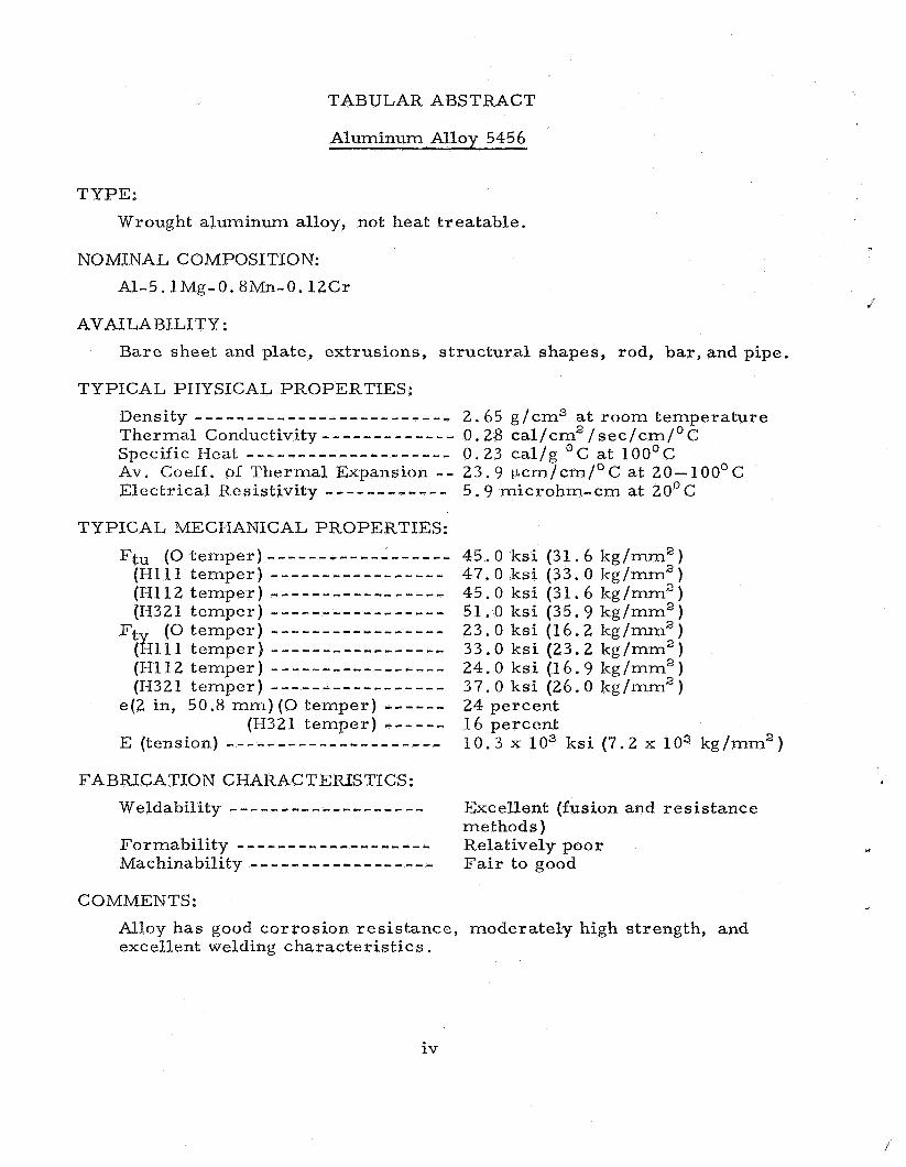
Wrought aluminum alloy, not heat treatable.
NO WNAL COMPOSITION:
A1-5.lMg-O.8Mn-O.lZCr
AVAILABILITY:
Bare sheet and plate, extrusions, structural shapes, rod, bar, and pipe.
TYPICAL PHYSICAL PROPERTIES: Density . . . . . . . . . . . . . . . . . . . . . . . . . 2.65 g/cm3 at room temperature Thermal Conductivity------------- 0.28 ca l /cm2/sec /cm/oC Specific Heat - - - - - - - - - - - - - - - - - - - - 0.23 cal /g OC at 100°C Av. Coeff. o f Thermal Expansion -- 23.9 pcm/cm/OC at 20-100°C Electrical Resistivity ------------ 5 .9 microhm-cm at 2OoC
45.0 ks i (31.6 kg/mm2) 47 .0 ks i (33.0 kg/mm2) 45.0 ks i (31.6 kg/mm2) 51.0 ks i (35.9 kg/mm2) 23.0 ksi (16.2 kg/mm") 33.0 k s i (23 .2 kg/mm2) 24.0 ks i (16.9 kg/mm") 37.0 ks i (26.0 kg/mm2) 24 percent 1 6 percent 10.3 x lo3 k s i (7.2 x l o a kglmm")
FABRICATION CHARACTERISTICS: Weldability - - - - - - - - - - - - - - - - - - - Formabili ty - - - - - - - - - - - - - - - - - - - Machinability ------------------ Fair to good
Excellent (fusion and resis tance methods ) Relatively poor .I
COMMENTS:
Alloy has good corrosion resis tance, moderately high strength, and excellent welding charac te r is tic s .
iv

SYMBOLS
4.
a A
ii AC AMs A3X-l ASTM Av o r Avg
B
b bcc BHN br Btu
OC C CD C F cm
CW CVM
D o r Dia DPH
e E EC e / D ES Et eV
OF f Fbru Fbry
One-half notch section dimension Area of c ros s section; lfAlf basis for mechanical property values (MIL- HD BK- 5A) Angstrom unit Air cool Ae r o space Mat e rial Spec if ic a t ions Annealed American Society for Testing Methods Average
llBfl basis for mechanical property values (MIL- HDBK-5A) Subs c r ip t "bending I t
Body centered cubic Brinell hardness number Subscript "bearing" Brit ish thermal unit(s)
Degree(s) Celsius Subscript "compression" Cold drawn Cold finished Centimeter Spec ific heat Cold rolled Cold worked Conswnable vacuum melted
Diameter Diamond pyramid hardness
Elongation in percent Modulus of elasticity, tension Modulus of elasticity, compression Ratio of edge distance to hole diameter Secant modulus Tangent modulus Electron volt (s )
Degree (s ) Fahrenheit Subscript I1fatigue1' Bearing ultimate strength Bearing yield strength
V

fcc FC
g G
HAZ hCP h r HT
IACS in ipm
OK
KC K
L l b LT
M m M Max ml MIL Min mm
N NSR NTS
OQ
PPm Pt
Face centered cubic Furnace cool Compressive yield strength Shear s t r e s s ; shear strength Ultimate tensile strength 0 .2% tensile yield strength (unless otherwise indicated)
Gram Modulus of rigidity
Heat affected zone in weldments Hexagonal close pack Hour (s ) Heat t r ea t
International ann e a1 e d c opp e r standard Inch Inches per minute
Degree(s) Kelvin S t ress intensity factor; thermal conductivity Measure of f racture toughness (plane s t r e s s ) at point of crack growth instability Ki logram Plane s t ra in f rac ture toughness value Thousand pounds per square inch Theoretical elastic s t r e s s concentration factor
Longitudinal Pound Long t ransverse (same as t ransverse)
Bending moment Met e r Sub s c r i p t I me ant Maximum Milliliter Military Minimum Millime t e r
Cycles to fai lure Notch strength ratio Notch tensile strength
Oil quench
Parts p e r million Point; par t
V i

r RA RB RC rPm RT
SA see S-N Spec ST STA
T t Temp typ
V a r VHN
w WQ
Radius Reduction in a rea ; Rockwell hardness A scale Rockwell hardness B scale Rockwell hardness C scale Revolutions pe r minute Room temperature
Solution anneal Second S = s t r e s s ; N = number of cycles Specifications; specimen Solution treat; short t ransverse Solution treated and aged
Transverse Thic kne s s ; time Temperature Typical
Variable Vicker s hardnes s number
Width Water quench
vii

CONVERSION FACTORS
To Convert To
angstrom units
Btu/lb/OF
Btu/ft2 /sec/" F-inch
circular mil
cubic feet
cubic feet/minute
cubic inches
feet
f o o t - pound s
gallons (U. S. )
inches
ks i (thousand pounds
microns
mils
ounces (avoir. )
ounces (U.S . fluid)
pounds (avoir . ) pounds /foot
pounds/cubic foot
square feet (U. S. )
square inches ( U . S . )
p e r square inch
millimeters
cal/g/O c ca1/g/cm2/sec/OC-cm
square cent imeters
cubic meters
l i ters /second
cubic cent imeters
meters
ki logram-meters
liters
millimeters
kilograms / square millimeter
millimeters
millimeters
g rams
mill i l i ters
kilograms
kilograms /meter
g r a m s /cubic centimeter
square meters
square cent imeters
Temperature in OC = (OF - 32) (5/9)
Temperature in OK = O C t 273.15
Multiply By
1 x 10⁻⁷
1
1.2404
5.067 075 x loe6 0.028 317
0.4720
16.387 162
0.304 800 609
0.138 255
3.785 411 784
25.4
0.70307
d
0.001
0.0254
28.349 527
29.5729
0.453 592 37
1.488 16 0.016 018 463
0.092 903 41
6.451 625 8
viii
Chapter 1
GENERAL INFORMATION
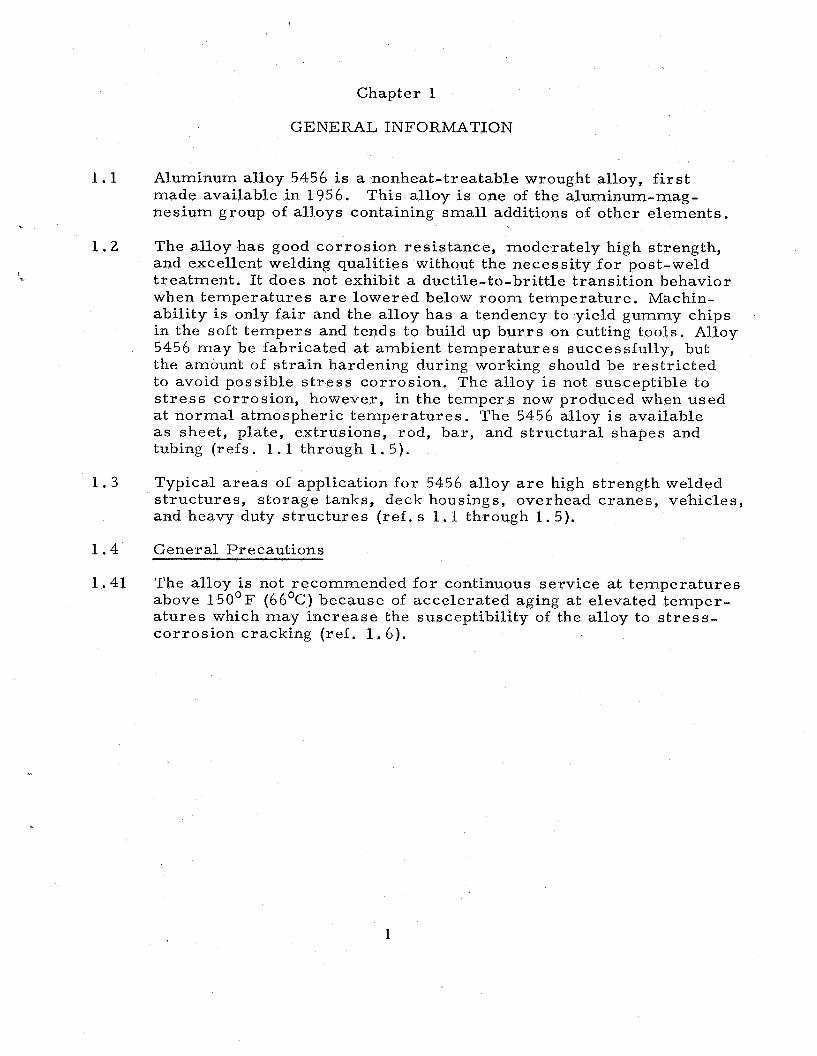
1 .1 Aluminum alloy 5456 is a nonheat-treatable wrought alloy, f i r s t made available in 1956. nesium group of alloys containing small additions of other elements.
The alloy has good corrosion resistance, moderately high strength, and excellent welding qualities without the necessity for post-weld treatment. It does not exhibit a ductile-to-brittle transition behavior when temperatures a r e lowered below room temperature. Machin- ability is only fair and the alloy has a tendency to yield gummy chips in the soft t empers and tends to build up b u r r s on cutting tools. Alloy 5456 may be fabricated at ambient temperatures successfully, but the amount of s t ra in hardening during working should be res t r ic ted to avoid possible s t r e s s corrosion. The alloy is not susceptible to s t r e s s corrosion, however, in the tempers now produced when used a t normal atmospheric temperatures . The 5456 alloy is available as sheet, plate, extrusions, rod, bar, and s t ructural shapes and tubing (refs. 1 . 1 through 1 .5) .
This alloy is one of the aluminum-mag-
1 . 2
4
1 . 3 Typical a r e a s of application for 5456 alloy are high strength welded s t ructures , storage tanks, deck housings, overhead cranes, vehicles, and heavy duty s t ruc tures (ref. s 1.1 through 1.5).
1 . 4 General Precautions
1.41 The alloy is not recommended f o r continuous service at temperatures above 150°F (66OC) because of accelerated aging a t elevated temper- a tures which may increase the susceptibility of the alloy to s t r e s s - corrosion cracking (ref , 1 . 6 ) .
1

Chapter 1 - References
1.1 Alloy Digest, 'tAluminum 5456" (Filing Code A1-70), Engineering Alloys Digest, Inc. , September 1958.
1.2 Aluminum Standards & Data: 1970-7 1 , The Aluminum As sociation, New York.
1 . 3 Materials in Design Engineering, Materials Selector Issue, Mid- October 1964.
d
1.4 Reynolds Metals Co. , "The Aluminum Data Book," 1965.
1 .5 Olin Aluminum, "Olin Aluminum Mill Products and Casting Alloys,I1 1970.
1 . 4 K. F. Thornton, Alcoa Aluminum- Magnesium Alloys, Suitable for Structural Welding Applications," Alcoa Green Letter, November 1959; revised by R,L. Flucker, August 1962.
1 .7 V . W e i s s and J. Sessler, Eds. , "Aerospace Structural Metals Hand- book, Vol. 11, Non-Ferrous Alloys," ASD TDR 63-741, 1971 Edition.
2
Chapter 2
PROCUREMENT INFORMATION
2 .1
2 . 2 b
2 . 3
2 .4
2.41
General. Aluminum alloy 5456 is available as sheet, plate, extru- sions (shapes and tube), s t ructural shapes, rod, bar , and pipe. Detailed tables of standard s izes and tolerances fo r the various products available a r e given in references 2.1 and 2 .2 .
Procurement Specifications. Specifications alloy a s of May 1971 a r e l isted in table 2 . 2 and tempers .
that apply to the 5456 for various products
Major Producers of the Alloy (United States only)
Aluminum Company of America 1501 Alcoa Building Pittsburgh, Pennsylvania
Kaiser Aluminum and Chemical Sales, h c . 919 North Michigan Avenue Chicago, Ulinois
Olin Aluminum/ Metals Division 460 Park Avenue New York, New York
Reynolds Metals Company 6601 West Broad Street Richmond, Virginia
Available Forms, Sizes, and Conditions
The available forms, s izes , conditions, and tolerances for various 5456 alloy products a r e given in detail in references 2.1 and 2 . 2 . Availability and dimensions of typical products a r e given in table 2.41.
3

TABLE 2.2. - Procurement Specifications (a, b)
Tube (extruded) Seamless tube
Structural shapes
(drawn)
{extruded o r rolled)
' 1
H323, H343 MIL-A- 19842C QQ-A-250 / 9 F
0, H111, H112 - 0 - c
0, H112, H311 MIL-A-25994, QQ-A-225C MIL-A-Z1170A
H111 MIL-A-21 170A QQ-A-2256
, 2.7
Armor plate(weldab1e) Extruded a r m o r Forced a r m o r
- - -
~
Federal
QQ- A- 200 / 7D QQ - A- 20 0 / 7 D
MIL- A-46027 D MIL - A- 46 0 8 3 -1 MIL- A- 4 5 2 2 5 B
.- e
- - -
ASTM
B221-71 -
B308-70 B308-70
B247-70
B241-70 B345-68
B209-71 B209-71 - B209-71 B209-71
B221-71 B210-70
~B308-68
lB308-68
(a) Specified as of May i971
(b) See also SAE Handbook No. AA5456 (ref. 2 .4)
J
4

b
TABLE 2.41. - Typical Availability and Size Ranges of Mill Products
5

2.1
2.2
2 . 3
2.4
2.5
2.6
2 .7
2.8
Chapter 2 - Rcferences
Aluminum Standards & Data: 1970-71, The Aluminum Association, New York.
Aluminum Co. of America, IIAlcoa Aluminum Handbook," 1962.
Aluminum Co. of America, "Alcoa Product Data - Specifications," Section A12A, July 1963.
1971 SAE Handbook, Society of Automotive Engineers, New York .
ASTM Standards, Part 6, Supplement, Nonferrous Metals Speci- fications, Electron Tube Materials, 1963; a l so Part 6, 1971.
Ae r o spa c e Mat e r ial Spe c if i cat ions, So c ie ty Automotive Eng ine e r s , Inc. , New York, latest Index, May 1971.
Index of Specifications and Standards , Part I, Alphabetical Listing and Part 11, Numerical Listing, Department of Defense, la tes t Index, May 1971.
Olin Aluminum, 'IOlin Aluminum Mill Products and Casting Alloys,f1 1970.
J
6

Chapter 3
METALLURGY
3.1 Chemical Composition
3.11 Nominal chemical composition of 5456 alloy, in percent (ref. 3.3):
Mg 5.1 Cr 0.12 Mn 0 .8 A1 Balance
3.12 Chemical composition l imits , in percent (ref. 3.11):
Mg 4.7-5.5 Ti 0.20 max Mn 0.50-1.0 Cu 0.10 max Cr 0.05-0.20 Others S i t F e 0.40 max Each 0.05 max Zn 0.25 max Total 0 ,15 max
Al Balance
3.13 Alloying elements. Magnesium is the major alloying constituent in the 5456 alloy, with l e s s e r quantities of manganese and chromium also present. Magnesium is soluble, while manganese (in the pres - ence of iron) and chromium are relatively insoluble. The aluminum- r ich portions of the binary diagrams for the aluminum-magnesium, aluminum-manganese, and aluminum-chromium systems are shown in figure 3.1. An aluminum-magnesium intermetallic compound can be formed, but i ts precipitation during an aging treatment dces not increase the strength of the alloy. Thus, the alloy is not strengthened by thermal treatments (refs. 3.4, 3.5, 3 .6) .
3 .2 Strengthening Mechanisms
3.21 General, The alloy is strengthened by a combination of solid solution strengthening and cold work. Cold working of this alloy is generally followed by a stabilization treatment, which is a high temperature aging treatment that permits most of the magnesium to remain in solid solution. This treatment improves the resis tance to corrosion of the alloy. Increase in magnesium and manganese content resul ts in strength increase with a corresponding decrease in ductility. The 5456 alloy has the highest magnesium content of any of the 5000 se r i e s of aluminum alloys (refs. 3.4, 3.5).
h 3.22 Heat Treatment. The alloy i s not strengthened by thermal treatments and is therefore considered to be nonheat-treatable.
3.221 Annealing (0 Condition). Heat to 343'C, hold a t temperature only for sufficient t ime to bring all par t s of the load to the annealing temper- ature. Cooling ra te is not cr i t ical ( ref . 3.1). An annealing temper- a ture of 413'C is also recommended (refs . 3.2, 3.4).
7

3.3 Critical Temperatures
Liquidus temperature 638'C Solidus temperature 571OC (ref. 3 . 4 ) .
3.31 The solid solubility of magnesium in aluminum is shown below (ref. 3.7):
Temperature, C 200 250 300 350 400 450
Weight-percent Mg 2.9 4 . 5 6.3 8.7 11.5 14.9
3.4 Crystal Structure Face centered cubic. The latt ice parameter depends pr imari ly on the amount of Mg in solution. F o r aluminum with no Mg, a. = 4.041 x mm and it increases to a. = 4.089 x aluminum with 10.75 atomic-percent Mg (ref. 3.6).
mm for
3.5 Microstructure. Data on the stable and metastable phase identifica- tion in A1-Mg alloys may be found in reference 3.10. The 5456 alloy also contains manganese and chromium. Phase identification of the relatively insoluble phases formed between aluminum, iron, man- ganese and silicon can be based largely on the studies for aluminum alloy 3003, with some modiiication due to the presence of chromium (ref. 3 .9) . References 3.8 and 3 . 9 a r e recommended as excellent sources of information on the identification of constituents in alum- inum alloys.
3.6 Metallographic Procedures . In general, mechanical polishing is prefer red to electropolishing, especially where l a rge r microcon- stituents a r e present and the mater ia l is relatively soft, because objectionable relief effects produced by the electrolytic technique may cause misinterpretation of the microstructure . F o r homogen- eous alloys, and for those containing finely dispersed particles (such as aged alloys), the electrolytic method is excellent. Most metallo- graphers prefer to replace the grinding step by mill filing. specimen i s then polished on metallographic emery papers 0 to 000, wet with a solution of 50 g paraffin in 1 liter kerosene to keep the specimen bright and avoid imbedding of emery particles into the soft specimen surface.
The
Following the final kerosene wash, the kerosene itself must be re- moved with water and alcohol. Polishing is accomplished by a water suspension of No. 600 alundum flour on broadcloth or gamal-cloth on a disk rotating a t about 300 rpm. performed on a disk revolving a t about 150 rpni. Miracloth, selvyt or "kitten's ear" broadcloth a r e used on the disk with levigated alumina or magnesium oxide in distilled water as the abrasive mixture.
Final polishing is carefully
An alternate and popular method consists of the following steps:
(a) Wet polishing (flowing water with 240 gr i t silicon carbide paper a t approximately 250 rpm.

(b)
(c)
(d)
Wet polishing with 600 gr i t silicon carbide paper a t approximately 250 rpm.
Polishing with 9 - p m diamond paste on nylon cloth a t 150 to 200 rpm using a mild soap solution fo r lubrication.
Final polish on a vibratory polisher using a microcloth containing a s lu r ry of methyl alcohol and 0.1-pm alum- inum oxide powder. A s lu r ry of 0.1 - p m aluminum oxide powder in a 10-percent solution of glycerine in distilled water may also be used for this step.
Etching reagents have to be suited to the objective of the study. Kellers etch reveals microstructural details and grain boundaries satisfactorily. A 10-percent solution of NaOH gives better detail of the microstructural constituents but does not delineate the grain boundaries. Study of the "as polished" surface pr ior to etching may also give valuable information on the types of con- stituents present, especially when attention is paid to the colors of the various par t ic les . Macroscopic studies f o r cracks, g r o s s defects, forging l ines and grain s t ructure should be made with the following etching solutions: 10-percent NaOH (cracks, g r o s s defects), Tucker's etc, modified Tucker's etch, and Flick's etch (ref. 3 .6) . These etching solutions f o r revealing the macrostruc- tu re a r e given in table 3 .1 .
9

TABLE 3 . 1 . - Etching Solutions for Rcvealing Macrostructure
Modified Tucker 's
Flick' s
HC1 (conc.) 10 ml For revealing s t ructure of HN03 (conc. ) 10 ml all castings and forgings H F (487'0) 5 ml except high-silicon alloys Water 75 ml
HC1 (conc. ) 15 ml For revealing grain s t ructure H F (48740) 10 ml of duraluminum type of Water 90 ml alloys. Surface should be
machined or rough polished
J
(a) All of these solutions a r e used at room temperature
10

a
Atomic Percentage Chromium
Aluminum - Chromium
Weight Percentage Chromium
Atomic Percentage Manganese
Weight Percentage Manganese
Aluminum - Magnesium
Aluminum - Manganese
Atomic Percentage Magnesium
AL 2 4 6 8 IO 12 14 16 I8 20 Weight Percentage Magnesium
FIGURE 3 . 1 . - Aluminum-rich portions of binary equilibrium diagrams. (Ref. 3 . 7 )
1 1

Chapter 3 - References
3.1 Aluminum Go. of America, "Alcoa Aluminum Handbook," 1962.
3.2 Reynolds Metals Go. , "The Aluminum Data Book," 1965.
3.3 Aluminum Standards & Data: 1970- 7 1 , The Alwninum As sociation, New York.
3.4 Metals Handbook, 8th Ed. , Vol. 1, "Properties and Selection of Metals, American Society for Metals, Metals Park, Ohio, 1961. J
3.5 Marshall Space Flight Center, "Effect of Low Temperatures on Structural Metals," NASA SP-5012, December 1964.
3 .6 W. L. Fink et al., Physical Metallurgy of Aluminum Alloys, American Society €or Metals, 1949; reprinted 1958.
3 .7 E. H. Wright and L. A. Willey, "Aluminum Binary Equilibrium Dia- grams,I1 Technical Paper No. 15, Aluminum Go. of America, 1960.
3 .8 F. Keller and G. W. Wilcox, I'Identification of Constituents of Aluminum Alloys," Technical Paper No. 7, Aluminum Co. of America, 1942; revised 1958.
3.9 J. P. Vidosic, "Study of Phase Identification in Steel and Aluminum Alloys," Georgia Institute of Technology, Final Report, Contract NAS8-5117, September 1963.
3.10 E. C. W. Per ryman and G, B. Brook, "Mechanism of Precipitation in Aluminum-Magnesium Alloys," J. Inst. Metals, - 79, 1 9 (1951).
3.11 1971 SAE Handbook, Society Automotive Engineers, Inc. , New York.
1 2

Chapter 4
PRODUCTION PRACTICES
4.1 General. In the United States, aluminum and its alloys a r e produced f r o m an o re of impure hydrated aluminum oxide known as ''bauxite,ll Important sources of bauxite a r e located in Arkansas, Dutch Guiana, and Jamaica. The impure o r e is converted into pure aluminum oxide (alumina) through a se r i e s of chemical processes . Oxygen is removed f rom the alumina by smelting in carbon-lined electric furn- aces known as reduction pots. Pure molten aluminum is deposited at the bottom of the pot, and is periodically siphoned off and poured into molds to form rrpigslt and lfsows." A separate furnace operation is used to fo rm Ifalloy pig" f rom the pure aluminum by the addition of alloying elements and this metal is cast into ingots f o r further processing (ref . 4.1).
';.
For the 5456 alloy, the major alloying elements added to the alum- inum a r e magnesium, manganese, and chromium. Generally, this phase of production pract ice involves the melting, alloying, and casting of la rge 20,000- to 50,000-pound (=9,000 to 21,000 kg) ingots, carefully controlled. After the ingots a r e scalped and preheated in ver t ical e lectr ic soaking pits, they a r e ready f o r further processing to a particular form of product.
4 .2 Manufacture of Wrought Products
4.21 Bar and rod are normally produced by hot rolling o r extruding. Cold finished bar and rod a r e produced by hot working to a s ize slightly l a rge r than specified and reducing to final dimensions by cold work- ing. A better sur face finish and closer dimensional tolerances a r e obtained in this manner ( ref . 4 .2) .
4.22 A similar process is used to produce rolled s t ructural shapes, but special rol ls a r e required. Finishing operations include ro l le r o r s t re tch straightening, and heat treatment,
4.23 Roll-form shapes a r e produced by passing s t r ip through a se r i e s of rol ler dies. Each successive pair of rol ls cause the work to assume a cross-sect ion shape m o r e nearly approaching that desired. The final desired shape is produced at the last pair of ro l l s ,
4.24 Plate is produced by hot rolling of ingots to slabs (approximately 6 0 - percent reduction), usually in a 4-high reversible mill. The slabs a r e then further reduced 50 percent in a reversible 2-high mill. The last stage of hot rolling is done in a hot reversing mill, where the plate is progressively rolled to the final hot mill dimensions. Strong alloy plate may be subjected to " s t r e s s relief" stretching (about 2 percent permanent se t ) to improve flatness and reduce warpage upon machining. Plate is then sheared o r sawed to the required dimen- sions (ref. 4 .2) .
13

4.25
4.26
4.27
4.28
I i
Sheet is usually produced from plate by cold rolling to final sheet thickness, followed by triinniing, tempering, heat treating, stretch- ing, and other finishing operations.
Wire i s produced by drawing rod through a s e r i e s of progressively smaller dies to obtain the desired dimensions.
Extrusions a r e produced by subjecting reheated cast billets to enough pressure to force the mctal to flow through a die orifice, forming a product whose cross-section shape and s ize conforms to that of the orifice. Speeds, p ressures , and temperatures must be closely controlled to insure uniform quality of extruded products. d
Tube i s produced by extruding, by drawing, or by welding. Extruded tube is forced through an orifice as described in 4.27; a die and mandrel a r e used. Drawn tube is manufactured by a cold process which is similar to drawing ba r and rod.
A mandrel is used with one end fixed and a bulb attached to the other end. The tube is drawn over the mandrel bulb and through a die a t the same time. Welded tube i s produced by slitting coil stock into s t r ips and passing the s t r ips through a se r i e s of rolls to form tube. The longitudinal s eam is welded as the tube leaves the l a s t roll forming station.
Forgings are made by pressing (press forging) or hammering (drop forging). Relatively heavy equipment is required since aluminum is not as plastic a t i ts forging temperature as steel. Aluminum forg- ings compare favorably with structural steel in unit strength a t about one-third thc weight. With comparable strength and with a lower elastic modulus, aluminum alloys have a much higher im- pact- energy- absorbing capac ity than mild steel.
Available Tempers (refs. 4.2, 4.4, 4 . 5 )
Aluminum alloy 5456 products a r e available from producers of the alloy in the following tempers:
4.29
4 . 3
4.31
H19
H24
H32, H3 8
H1 11
Strain hardened to ultimate tensile strength grea te r than can be achieved by cold reduction.
Strain hardened and then partially annealed to half-hard condition.
Strain hardened and stabilized by low temperature t reat- ment which resul ts in slightly less tensile strength and imp roved ductility.
Strain hardened only to obtain the desired mechanical properties with no thermal treatment. Applies to products which a r e s t ra in hardened l e s s than the amount required for a controlled H11 temper.
14

H112 Temper is acquired f rom shaping processes not having special control over the amount of s t ra in ahrdening or thermal treatment but for which mechanical property limits or testing is required.
Strain hardened and stabilized to one-quarter hard con- dition by a low temperature heating operation which pre- vents age softening at room temperature . H321, H322, and H323 a r e variations of the controlled H32 temper.
Strain hardened and stabilized to one-half hard condition. This temperature is a variation of the controlled H34 temper .
H321
H343
4.4 Casting of Alloy Ingots
4.41 Metal for wrought products is alloyed in l a rge 10- to 25-ton double hearth furnaces, carefully controlled and instrumented. The d i rec t chill (DC) method is generally used f o r casting these ingots. Molten metal is poured into a mold and a hydraulic piston descends slowly as the metal solidifes. Water i s spryaed on the outside of the mold to promote rapid solidification. Additional processing may include scalping (machining of outside surfaces) or homogenizing (refs . 4 .2 , 4.3).
1 5

Chapter 4 - References
4 .1 Kaiser Aluminum and Chemical Sales, Inc., "Kaiser Aluminum Sheet and Plate Product Information," 2nd Edition, January 1958.
4 . 2 Reynolds Metals Go. , "The Aluminum Data Book, Aluminum Alloys and Mill Products," 1958.
4 . 3 Aluminum Co. of America, llAlcoa Aluminum Handbook," 1962.
4 .4 Aluminum Standards & Data: 1970- 7 1, The Aluminum As sociation, d
New York.
4.5 Olin Aluminum, "Olin Aluminum Mill Products and Casting Alloys," 1970.
16

5 . 1
Chapter 5
MANUFACTURING PRACTICES
General. The nonheat-treatable 5456 alloy is one of the aluminum- magnesium se r i e s which finds principal application in s t ructures that a r e fabricated predominately from sheet and plate and where welding is the method of joining (ref. 5.5). Most of these s t ruc tures a r e designed on the basis of strength and ductility of welds and in- clude dump trucks, rock bodies, bulk haulers, truck tanks, boats, cryogenic tanks and equipment, chemical processing equipment, and elevators for aircraft c a r r i e r s . Several other applications a r e the f i r s t stage of the Saturn I and Saturn IB launch vehicles, a 140-ft diameter radio-telescope in the form of a fabricated parabolic dish, and the elevator for the nuclear-powered c a r r i e r Enterpr ise (ref. 5 .6) .
5 .2 Forming
5.21 Sheet and Plate. The general formability of 5456 a s a sheet mater ia l i s considered to be limited compared to other nonheat-treatable alloys; it i s rated as the most difficult to form, a s indicated in table 5.21.
5.211 Cold Forming. The high strength of this alloy in not only the s t ra in- hardened tempers but a lso the annealed temper r e s t r i c t s the capability f o r withstanding severe forming operations. Table 5.21 1 l i s t s typical propert ies for 5456 sheet below 0.200-in (5.08 mm) thickness f o r severa l tempers and the corresponding recommended minimum bend radii . The H3 temper resul ts from a stabilizing treatment. Cold- worked 5456 would tend to age-soften at room temperature. A thermal treatment at about 350'F (177'C) prevents this from happen- ing (ref . 5 .8) . The specially developed H343 temper produces a metallurgical condition which shows excellent res is tance to s t r e s s corrosion. Cold-worked 5456 may be susceptible to s t r e s s corrosion at temperatures above 150'F (65OC). If cold forming in excess of the established minimum l imits is employed, a s t r e s s relief anneal of 4 hours a t 450' k25'F (232' h13OC) will res tore the good res i s t - ance to corrosion.
Aluminum sheets a r e normally formed using operations such as:
1. Bending 9. Stamping 2. Flanging 10 . Spinning 3. Rolling 11. Contour forming 4. Drawing 12. Bulging and expanding 5. Pressing 13. Beading and roll flanging 6. Stretching 14. Necking 7. Embossing 15. Curling 8. Coining
17

The factors influencing bending of 5456 sheet, as described previously, a lso influence the fourteen other forming operations in the same gen- e ra l manner. Because of thc lowcr modulus of elasticity of aluminum compared with steel, a much grea te r “springback’’ is expected and is encountered. Overforining is the common way of correcting the tend- ency. In addition, reducing the bend radius, increasing sheet thick- ness , forming at elevated temperatures , and increasing the total amount of plastic deformation decrease the extent of springback. Alloy 5456 sheets can be iornicd to many shapes by drawing; this is the most extensively employed mass production method. Depending upon the desired shape, the par t may be produced in one draw or in some cases the reduction i s accomplished in successive draws using frequent annealing between successive draws to avoid exhausting the ductility and introducing cracks . Deep draws normally employ male and female metal dies . Forming in rubber (Guerin process) for re l - atively shallow par t s , is a method where several thin layers 01 rub- ber a r e confined in a pad holdcr o r re ta iner made of s teel or cast i r o n . A descending ram on which this holder is mounted causes the aluminum sheet to be compressed against a form block to make the required part . If the aluminum is made to flow against a female die, using fluid p re s su res behind a rubber diaphragm, the method is known as hydroforming.
Other techniques such as spinning and high- energy- ra te methods have also been successful.
Tapered plate was developed by one of the aluminum producers about 1950 f o r use in je t a i rc raf t . Alloy 5456, rolled in a heavily powered screw-down plate-rolling mill to a taper section, is being used for l a rge (125 feet in diametcr, 48 feet high), flat-bottom ammonium ni t ra te storage tanks. The l a r g e r dimension of each plate thickness is utilized in the lower portions of the tank taper ing to the l e s s heavily s t ressed upper portions. The tapered plate tank saves from 5 to 10 percent in mater ia l compared to the conventional t iered o r shell-plate construction. (Tank dimensions equivalent to 38 m x 15 m. )
It i s the combination of properties and fabrication character is t ics which a r e the significant factors leading to the selection of 5456 f o r a i r c ra f t applications. The 5456 alloy is commonly used in a i rc raf t applications for spun or drawn p res su re receptacles. Spinning is a specialized forming, operation in which the work is forced against a chuck or fo rm block while rotating. The chucks a r e usually made of hardwood (maple) o r segmented and laminated construction (ref. 5 .7) . The segments a r e f i rmly glued together, joints a r e staggered, and each t ie r is solidly glued to the adjoining one or fastened with heavy wood screws . For la rge quantity production, chucks can be of carbon s teel for shallow spinnings and of cast iron or alloy cas t iron for deeper ones. Generally, spinning is devoted to concentric par t s . There is n o maximum size for spinning except as limited by existing equipment or material . Spinning requires considerable axial p re s su re which can be accommodated on horizontal lathes or vert ical boring mills. Hot spinning to a s s i s t metal flow and reduce the spinning p res su re is sometimes used.
18

5.212 Hot Forming. W a r m forming for l e s s severe configurations can be pcrPormed a t 425" rtr25"F (218" t 3°C). This will avoid the adverse cIIect of cold work and high residual s t r e s s e s .
5.22 Shapes, Tubes, and Pipes. Either extrusion o r rolling can be used to produce aluminum shapes. The standard shapes a r e I-beams, €3- beams, channels, angles, teez, and zees. The relative formability of alloy 5456 a s tubes o r extrusions can be noted in table 5.21. In this form, the tubes o r extrusions can be heated a t 650'F (343OC) to produce the 0 temper .
5.23 Forgings. The 5456 alloy can be used for forgings in the H112 temper with sections up to about 4-inch (10-cni) maximum thickness. Forgings a r e made using either the open die o r closed die methods and by impact o r pressure . Small runs a r e made using hand-forging o r open-die techniques. The process for most production forgings s t a r t s with the stock which can vary f r o m 3/8-inch to 8-inch diam- e te r round stock; f rom 3/8-inch to 4-inch square stock, and rect- angles from 3/8 inch for the minimum dimension to as much as 1 0 inches on the maximum dimension. (Note: 1 inch = 25.4 mm.) Conditioning to remove localized surface defects is permitted at this
in one step o r in the case of complicated pa r t s in several operations, involving several rcheatings. The €lash resulting f rom excess metal overfilling the mold is removed by hot o r cold trimming, sawing, o r grinding.
oint. The stock is carefully heated in the range of 650" to 875'F (393 2 - lo 468'C). After preheating, the stock can be forged to shape
Very close tolerances can be m e t in the standard forging by die coin- ing (cold) to precise dimensions, usually within a iew thousandths of an inch. Straightening after heat treatment i s often a required oper- ation. Templates combined with indicators and other gages a r e used to determine the out-of-tolerances. Straightening ranges f rom hand straightening to "cold restr ike" operations.
The forgings a r e inspected for grain flow, mechanical properties, dimensions and ultrasonic soundness. is available f rom the Aluminum Association (ref. 5.13).
A design manual for forgings
5 . 3 Machining
5.31 Conventional Machining. This alloy has machining qualities which a r e close to those of other nonheat-treatable aluminum alloys (such as 5154) though somewhat better than the lower strength alloys (ref. 5.12). High- speed s teel cutting tools a r e satisfactory, but hard-carbide grades a r e prefer red . Sin l e point tools should have 20'-50' top rake, 10°-200 side rake, 8'-10 ting is to be done a t high speeds and fine to medium feeds. Cutting edges must be kcen, smooth, and f ree f rom grinding scratches. Turn- ings are continuous, tough, and somwhat difficult to cur l . In soft tempers , the turnings a r c somewhat gummy and tend to build up b u r r s
E front and side clearance angles. The cut-
1 9
on thc: tool. For many purposes, a soluble cutting oil is good. How- ever, a kerosene-lard oil mixture is preferred.
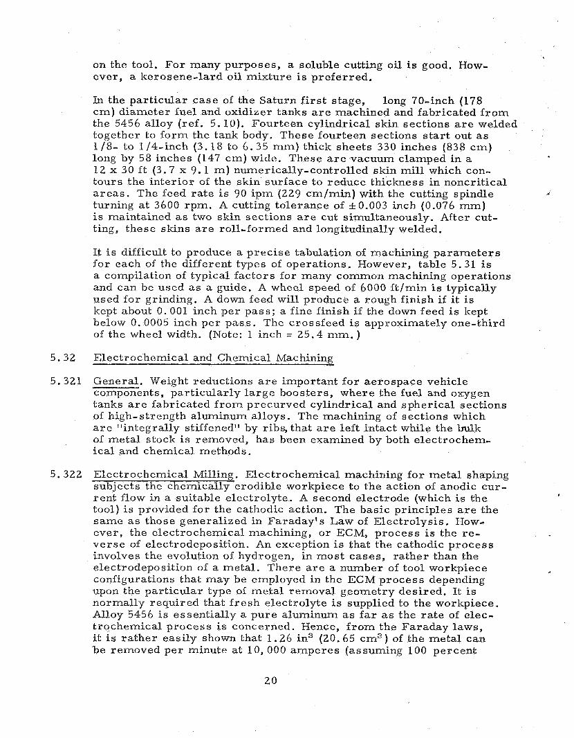
In the particular case of the Saturn first stage, c m ) diameter fuel and oxidizcr tanks a r e machined and fabricated f r o m the 5456 alloy (ref . 5.10). Fourteen cylindrical skin sections a r e welded together to form the tank body. These fourteen sections s ta r t out as 1 /8- to l /4 - inch (3.18 to 6.35 mm) thick sheets 330 inches (838 c m ) long by 58 inches (147 c m ) wictc. These a r e vacuum clamped in a 12 x 30 ft (3.7 x 9 .1 m) numerically-controlled skin mill which con- tours the interior of the skin surface to reduce thickness in noncritical a r e a s . The ieed ra te is 90 ipm (229 cm/min) with the cutting spindle turning a t 3600 rpm. A cutting tolerance of f0 .003 inch (0.076 mm) is maintained as two skin sections a r e cut simultaneously. After cut- ting, these skins a r e roll-formed and longitudinally welded.
long 70-inch (178
It is difficult to produce a prec ise tabulation of machining parameters f o r each of the different types of operations. However, table 5.31 is a compilation of typical fac tors for many common machining operations and can be used as a guide. A wheel speed of 6000 f t /min is typically used for grinding. A down feed will produce a rough finish if it is kept about 0 .001 inch per pass ; a fine i inish i f the down feed is kept below 0.0005 inch per pas s . The crossfced is approximately one-third of the wheel width. (Note: 1 inch = 25.4 mm. )
5.32 Electrochemical and Chemical Machining
5.321 General. Weight reductions a r e important f o r aerospace vehicle components, particularly l a rge boosters, where the fuel and oxygen tanks a r e iabricated f r o m precurved cylindrical and spherical sections of high-strength aluminum alloys. The machining of sections which a r e "integrally stiffened" by ribs, that a r e left intact while the bulk of metal stock is removed, has been examined by both electrochem- ical and chemical methods.
5.322 Electrochemical Milling. Electrochemical machining for metal shaping subjects the chemically erodible workpiece to the action of anodic cur- rent flow in a suitable electrolyte. A second electrode (which is the tool) i s provided fo r the cathodic action. The basic principles are the same a s those generalized in Faraday's Law of Electrolysis. How- ever, the electrochemical machining, o r ECM, process is the re- ve r se of electrodeposition. An exception is that the cathodic process involves the evolution of hydrogen, in most cases , ra ther than the electrodeposition of a metal . There a r e a number of tool workpiece configurations that may be employed in the ECM process depending upon the particular type of meta l removal geometry desired. It is normally required that f r e s h electrolyte is supplied to the workpiece. Alloy 5456 is essentially a pure aluminum as far as the r a t e of elec- trochemical process is concerned. Hence, f r o m the Faraday laws, it is ra ther easily shown that 1 . 2 6 in3 (20.65 cm") of the metal can be removed per minute a t 1 0 , 0 0 0 amperes (assuming 100 percent
20

cf~icicncy). In practice, eflicicncies 01 80 to 90 percent a r e en- countcrcxl. An clectrolytc of 5 to 10 percent NaCl solution has been found to yield cxccllent rcsnl ts and tho process can be car r ied out using voltagcs of 10-15 volts. The milling ra te of the ECM process depends upon the current capacity of' the power supply and the ability o€ the electrolyte system to provide f r e s h electrolyte. High elec- trolyte pressure requirements of 100-250 ps i (0.07-0.18 kg/mm2) provide even electrolyte flow and satisfactory cutting conditions. Temperatures of about 120°F (5OoC) produce good quality finishes.
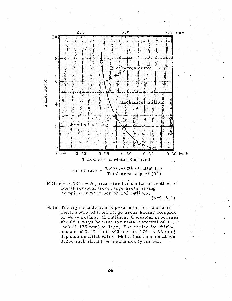
5 . 323 Chemical Milling. The removal of metal stock by chemical dissol- ution o r I1chem-milling1' in general has also many potential advantages over conventional milling mcthods. Thc removal of metal by dissolv- ing jn an alkaline or acid solution is now routine for specialized operations on aluminum (rc1. 5 .1) . For flat par ts on which large a r e a s having complex o r wavy peripheral outlines a r e to be reduced only slightly in thickness, eheinical milling is usually the most econ- omical method. The curve shown in i igure 5. 323 is typical for select- ing chemical or rncchanical milling.
d
21

TABLE 5.21. - Rc%lative Formabili ty of Nonheat- Treatable
Aluminum Alloys in Order of Decreasing Formabili ty I I
Source
Rating
1 Oh0 EC 1100 3003, No.l.1, No.12 5005 5357, 5457, 5657 5050 5052, 5652 3004, 5154, 5254 5454 5086 5083 5456
Ref. 5 . 7
S lie e t Mat e r ial s Ext ru s ions I
F k s i ( c ) e ( d ) t Y
min max min
19 - 1 6 33 46 1 2 36 46 6 41 52 6
1060 EC 1100 3003 5052 5154 5454 5086 5083 5456
Thicknesses, t, inch (c)
1 / 1 6 1 / 8 3/16 1 / 4 3 / 8 1 / 2
- 0- l t 1/2-lt 1/2-lt 1/2-11/2 1/2-2t - 2-3t 3-4t 3-4t 3-4t 3-4t 1 -2 t 11/2-3t 11/2-31/2t 2-4t - - 1-2t 11/2-3t 2-4t 21/2-41/2t - -
Tubes
1060 EC 1100 3003 5050 5052 3004,5154 5454 5086 5083 5456
min
42 46 48 53
TABLE 5. 21 1 , - Approximate Bend Radii for 90-Degree Cold Bend (a, b )
lsourcc I Rei. 5.4 1
max
53 59 58 63
Alloy
Tempe
0 H321 H323 H343
(a) Radii f o r various thicknesses expressed in t e r m s of thickness, t.
(b) Mechanical propert ies (Ftu, Fty, and e ) a r e minimum o r maximum for thicknesses below 0.200.
(c) 1 ks i = 0.70307 kg/mm2; 1 inch = 25.4 mrn. (d) Elongation, percent in 2-in gage section.
22

k 0
+I
cn k 0 U JJ
t A cd U
P + E
I
.rl
d cr)
m
3 0 0 0 0 0 0 0 0 0 0 0 0 . . . . . . . .I . .I . . .I 3 0 0 0 0 0 0 0 0 0 0 0 0
3 0 0 0 0 0 0 0 0 0 0 0 0 ~ m m m m m m m o o o o o N ~ N N ~ N N N r - ~ O O O
4 4 4
a, k cd Ft @ rn
23
2 . 5 5 .0 7 . 5 mm 1 0
8
6
4
2
0 0.05 0.10 0.15 0.20 0.25 0.30 inch
Thickness of Metal Removed
Total length of fillet (ft) Total a r e a of part (ft’)
Fil let ratio =
FIGURE 5.323. - A parameter fo r choice of method oi metal removal f r o m la rge a r e a s having complex o r wavy peripheral outlines.
(Ref. 5 .1 )
Note: The figure indicates a parameter for choice of metal removal f r o m la rge areas having complex o r wavy peripheral outlines. Chemical processes should always be used for metal removal of 0.125 inch (3.175 mm) or l e s s . The choice for thick- nesses of 0,125 to 0.250 inch (3.175-6.35 rnm) depends on fi l let ra t io . Metal thicknesses above 0.250 inch should be mechanically milled.
*
24

Chapter 5 - References
5.1
5.2
5 .3
I 5.4
5.5
5.6
5 .7
5.8
5.9
5.10
5.11
5.12
5.13
5.14
5.15
5.16
Metals Handbook, 8th Ed. , Vol. 1, "Propert ies and Selection of Metals," American Society f o r Metals, Metals Park, Ohio, 1961.
Aluminum Co. of America, "Alcoa Aluminum Handbook," 1962.
Materials in Design Engineering, IIWrought Aluminum and Its Alloys," June 1965, p. 117.
Aluminum Standards & Data: 1970-71, The Aluminum Association, New York.
Metal P rogres s , "What Metal Shall I Use. . for High Strength Weld Structure," Octcber 1961, p. 121.
Metal P rogres s , "Progress in Aluminum Alloys," October 1960, p. 137.
Reynolds Metals Company, "Forming Aluminum," 1961.
1, June 1965, p. 120.
F. L. Siegrist, "How to Do More with Wrought Aluminum Alloys," Metal P rogres s , October 1962, p. 124.
E. J . Bulban, 'Vought Producing C- 1 First Stage Tanks,I' Aviation Week and Space Technology, May 21, 1962, p. 54.
Machining Data, ORDP 40-1, July 1961.
Kaiser Aluminum, "Temporary District Engineering Data Sheet, Aluminum 5456 . I f
The Aluminum Association, "Aluminum Forging Design Manual,!' 1970.
Metals Handbook, Vol. 3, "Machining, American Society for Metals, Metals Park , Ohio, 1967.
Metals Handbook, Vol. 5, American Society for Metals, Metals Park, Ohio, 1970.
,Metals Handbook, Vol. 4, "Forming," American Society for Metals, Metals Park , Ohio, 1969.
25

a

Chapter 6
SPACE ENVIRONMENT EFFECTS
6 . 1 General. Aluminum alloys have been used in both s t ructural and nonstruc- tural applications in launch vehicles and spacecraft with excellent success since, in general, the aluminum alloys are relatively insensitive to de- gradation in typical space environment conditions. The vapor p re s su res of the s t ructural aluminum alloys a r e sufficiently high (table 6 .1) so that the combined temperature-vacuum effects generally a r e negligible. Struc- tural alloys such as 5456 are sufficiently hardened so that nuclear and space indigenous radiation indusced defects do not significantly affect mechanical and physical propert ies , at room ambient and elevated temper- a tures , below accumulated doses of about par t ic les /cm”. When ir- radiated at cryogenic temperatures , the threshold may be lowered one o r two decades, but the probabilities of experiencing doses on this o rde r of magnitude a r e extremely remote except in the vicinity of nuclear reac tors .
Elevated temperatures, hard vacuums, high energy radiations, and micro- meteoroids can singularly and collectively influence surface character- is t ics of 5456 by desorption processes and erosion. These phenomena might be of grea t importance if optical properties, lubrication, certain electrical propert ies , e tc . , were cr i t ical design parameters . Sputtering of the sur - face by atomic o r molecular par t ic les can deter iorate surface finishes in a relatively short period. A 3 0 0 - L coating of aluminum ( l o m 6 g / c m ” ) can be destroyed in one month during a period of low intensity solar wind o r in several hours during a solar s torm, for example. Estimates of su r - face erosion by sputtering are given in table 6 . 2 for aluminum alloys.
Micrometeoroids can produce surface erosion similar to sputtering, al- though perhaps on a more macroscopic scale, as well as punctures. Micro- meteoroids vary widely in mass, composition, velocity, and flus; gener- alizations about the ra tes of erosion and penetration, therefore, mus t be used with care . The predicted and measured frequency of impact as a function of meteoroid m a s s is given in figure 6 . 1 . Data a r e given in figures 6 . 2 and 6 .3 on the penetration and cratering of aluminum alloy skins of various thicknesses. Calculations of a r m o r thickness required for protec- tion of different s t ructures and orientations are given in table 6.3. The design of bumper-hull meteoroid protection systems is discussed in ref- erence 6.12.
The surface erosion of aluminum alloys due to corpuscular radiation i s probably insignificant, amounting to something of the order of 254 n m per year . Indigenous space radiation, however, will tend to accelerate the r e - moval of surface films, which might resul t in l o s s of lubricity and a n in- c reased propensity to “cold weld .I1 The interaction of indigenous radiation with desorption gases might cause some spurious, transient e lectr ical conditions when aluminum alloys are used for electrical applications a The interaction of indigenous radiation with the alloys may produce some in- ternal heating that might be significant for small items and may induce s ome radioactivity .
27

TABLE 6.1. - Evaporation Rates in Vacuum of Typical Elements
Used in Aerospace Alloys (a, b) ~
Source
Element
Aluminum
Titanium
Iron
Nickel
Copper
Chromium
Vanadium
Manganese
Si1 i c on
Magnesium
Zinc
Ref. 6 . 1 4
-1oooc 1.2 x 10'81
<10-99
<10-99
4 0 - 9 9
1.2 10-94
9.5
4 0 - 9 9
2 .2 x 10-7i
<10-99
3 . 5 1 0 4
2 . 9 x
Evaporation Rate, g / c m 2 / s e c
oo c L. 1 10-48
2.5 x
5.8 x 5.7 x 10-7O
1 . o x 10-54
1 . 1
1.4 x
1.9 x lo-*?
1.9 x 5 .3 x
5.1 x
5000c 6.5 x
2 . 0 x 10-1"
9 . 1 10-17
4.7 1 0 - 1 4
2.2 x 10⁻¹³
1 .2 1 0 - ~ 4
1.6 10-9
5.5 x 10- l6
6.6 x
2.80
1.7 x
(a) The actual evaporation ra te of each element in Combination with others will be lower.
'(b) The values may be in e r r o r by several o rde r s of magnitude as they have been extrapolated f r o m high- temperature data. The r a t e s a t low tempeatures will be considerably l e s s than the values given in the table.
28

TABLE 6.2. -Estimated Rate of Removal and Time to Remove
1 x mm of Aluminum by Sputtering
( s o u r c e I Ref. 6 .2 1
Source
Structure
Plane
Cylinder
Sphere
4
Ref. 6 .11
Crit ical Av. No. of Vulnerable Prob’y No Destructive Destructive Thickness
cm Impacts per Mission
Area Orientation (a) f t ” cm” Impact, 70 in
i, leading 1000 92.9 99.5 0.005 0.209 0.530 500 46.5 99.75 0.0025 0.209 0.530
i, trailing 1000 92.9 99.5 0.005 0.109 0.278 500 46.5 99.75 0.0025 0.109 0.278
j , ei ther 2000 185.8 99.0 0.01 0.232 0.590 side alone 1000 92.9 99.5 0.005 0.232 0.590
k, either 2000 185.8 99.0 0.01 0.197 0.500 side alone 1000 92.9 99.5 0.005 0.197 0.500
i 2000 185.8 99.0 0.01 0.215 0.547 j 2000 185.8 99.0 0.01 0.190 0.481 k 2000 185.8 99.0 0.01 0.205 0.521
(random) 2000 185.8 99.0 0.01 0.198 0.502
29

4
3
rr 0” -I
E -2 0
(u
\
tl Ja -3
- -4 s C
2
-6
-7
-8
-9
- IO -11
\ McCRACKEN, ALEXANDER, DUBlM 1961 \e
FIGURE 6 . 1 . - Various estimates of meteoroid m a s s influx.
(Ref. 6 . 3 )
30

03
O0
m c, E 0- 7
0-9
0-1 1
FIGURE 6.2. - Hit rate vs crater depth in the earth neighborhood but without earth shielding.
(Ref. 6 . 4 )
FIGURE 6.3 . -Sheet thickness of A1 as a function of the surface area-lifetime pro- duct required for various probabilities of no meteoroid puncture.
(Ref. 6 .1 )
31

Chapter 6 - References
6.1 C.G. Goetzel, J . B. Rittenhouse, and J .B . Singletary, Eds., Space Materials Handbook, Addison- Wesley Press, Palo Alto, California, 1965.
6 .2 J . R. Redus, ttSputtering of a Vehicle Surface in a Space Envir- onmcnt," NASA T N D-1113, June 1962.
6 .3 SAMPE, The Effects of the Space Environment on Materials, Western Periodicals Co. , North Hollywood, California, 1967.
6 . 4 L. E. Kaechele and A. E. Olshaker, "Meteoroids - implications fo r the design of spacc structures," Aerospace Engineering, 19, May 1960.
-
6 5 K. S. Clifton and P. J . Naurnann, "Pegasus Satellite Measurements of Meteoroid Penetration," NASA T M X-1316, 1966.
6 . 6 F. L. Whipple, "On Meteoroids and Penetration," J. Geophys, Res ., - 68, 4929 (1963).
6 .7 H. C . van de Julst, 'IZodiacal Light i n the Solar Corona,tf Astro- phys. J . , 105, 471 (1947).
6 . 8 F. G. Watson, Between the Planets, The Blakiston G o . , Phila- delphia, 1941; revised, Harvard University Press, Cambridge, Mass. , 1956.
6.9 C. W. McCracken et al., "Direct Measurements of Interplanetary Dust Par t ic les in the Vicinity of the Earth," Nature, - 192; 441 (1961).
6.10 R. J . Naumann, "The Near-Earth Meteoroid Environment," NASA TN D-3717, November 1966.
6.11 C. D. Miller, "Meteoroid Hazard Evaluation f o r Simple Structures with Various Orientations,Il NASA TN D-6056, October 1970.
6.12 6. R. Nysmith, "A Discussion of the Modes of Failure of Bumper- Hull Structures with Applications to the Meteoroid Hazard," NASA TN D-6039, October 1970.
6.13 W. M. Alexander et al. , "Zodiacal Dust: Measurement by Mariner IVYtt Science, - 106, 1240 (1965).
6.14 S. Dushman, Vacuum Techniques, John Wiley & Sons, New York, 1949.
32

Chapter 7
STATIC MECHANICAL PROPERTIES
7.1
7.11 7.12 7.13 7.14
L 7. 15 7.151 7.16 7.161
7.2
7.21 7.22 7.221
7.222 7.223 7.224 7.23 7.231
7.24 7.241
7.25 7.251
7.26
7.3
7.31
7.4
7.41 7.411
Spec i f ied Proper t ie s
NASA specified properties. None. AMs specified properties Military spec if ied p roper t ie s Federal specified propert ies AS T M spec if ied prop e r tie s ASTM specified properties are given in reference 7.3. Aluminum As sociation mechanical property limits Alurninum As sociation mechanical property limits a r e given in reference 7.4.
Elastic Propert ies and Moduli
Poisson’s ratio, 0.33 (ref . 7.5). Young’s modulus of elasticity, E Design value of E for sheet and plate and extrusions at room temp- erature , 10 .2 x l o 3 ks i (7.17 x l o 3 kg/mm2) ( re f . 7 .1) . Typical value of E, 10.3 x 10³ksi (7.24 x l o 3 kg /mm”) (refs.7.6,7.8). Modulus of elasticity a t low and room temperature, figure 7.223. Modulus of elasticity a t elevated temperatures, figure 7.224. Compression modulus, E,. Design value of E, at room temperature, 10.4 x l o 3 ks i (7.31 x l o 3 kg /mm2) (ref. 7 .1) Modulus of rigidity (shear modulus), G. Design value of G at room temperature, 3.85 x l o 3 ks i (2.71 x lo3 kg/mm”) (ref. 7 .1) . Tangent modulus Compressive tangent modulus curves for alloy in various forms and tempers, f igure 7.251. Secant modulus
Hardness
Brinell scale (500-kg load)
Condition 0 70 H112 70 H311 75 H321 90 H323 90 H343 94 (ref . 7.8)
Strength Propert ies
Tension (see also section 7.46) Design tensile properties
33

7.4111
7.4112
7.412 7.4121
7.4142
7.413 7.4131
7.4132
7.4133
7.4134
7.4135
7.42 7.421 7.4211
7.422 7.4221
7.43 7.44 7.441 7.4411
7.45 7.451 7.4511
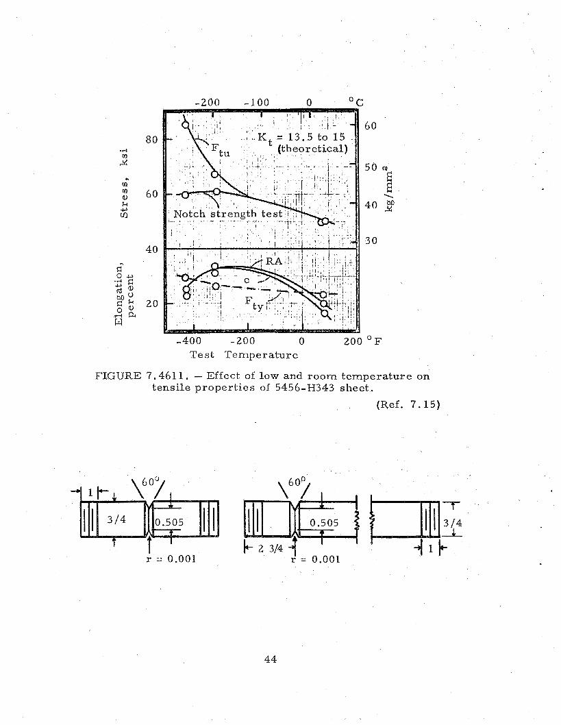
7.46 7.461 7.4611
7.4612
7.4613
7.4614
7.4615
7.462 7.4621
Design properties for sheet, plate, and extruded bar, rod and shapes, table 7.4111. Aluminum As sociation tensile property limits for sheet and plate i n various tempers , table 7.4112. Stress- s t ra in diagrams (tension) Typical s t ress -s t ra in curves at room temperature for extrusions, figure 7.4121. Typical s t ress -s t ra in curves f o r 5456-H321 plate at room temp- erature , i igure 7.4122. Effect o€ tes t temperature on tensile properties Effect of low and elevated temperature on the tensile properties of alloy in condition 0, figure 7.41 31. Effect of low and room temperature on tensile properties of sheet in condition H321, i igure 7.4132. Effect of low and room temperature on t ransverse and longitudinal tensile properties of sheet in condition H343, figure 7.4133. Effect of low and room temperature on tensile properties of sheet in condition H343, figure 7.4134. Effect of low and room temperature on tensile properties of sheet and plate in condition H343, figure 7.4135. Comp r e s s ion Design compression properties Design compression properties €or sheet and plate and extruded bar, rod, and shapes, see table 7.4111. Str e s s- s t ra in diagram [ compre s sion) Stress-s t ra in curves a t r o o m temperature for various forms and tempers , see figures 7.4121 and 7.4122. Bending Shear and torsion Design shear properties Design shear properties f o r sheet and plate and extruded bar , rod, and shapes, s ee table 7.41 11. Bearing Design bearing properties Design bearing properties f o r sheet and plate and extruded bar, rod, and shapes, s e e table 7.4111. Fr a c tur e Notch strength Effect of low and room temperature on tensile properties and notch strength of plate in 0 condition, figure 7.4611. Effect of low and room temperature on notch strength of sheet in H343 condition, figure 7.4612. Effect of low and room temperature on notch strength ratio of sheet in H343 condition, i igure 7.461 3. Tensile and sharp notch propert ies of sheet at room and low temp- e ra tures , figure 7.4614. Effect of low and room temperature on tensile properties and notch strength of plate in H321 condition, figure 7.4615. Frac ture toughness (plane s t r e s s ) Effect of low temperature on fracture toughness of sheet in H343 condition, f igure 7.4621.
34

I/, VI uj
I I
m
m
m I
I
. . . . . . . . 9 ; 8 ; . : : : : : : : 2 . . . . . . . . . . . . . . . . . . . . . . . . . . . . . . . . . . . . . . . . . . . . . a : 2: 2 ; ; : : : : 2
88 G% q E!g *
. . . . . . . . . . . . . . . . . . . . . . . . . . . . PC
. . . . . . . . q i 8 ; : : : :*: : : 51! . . . . . . . . . . . . . . . . . . . . . . . . . . . . . . . . . . . . . . . $Q 2 8 248Z $22 33 I",
35

TABLE 7.4112. - Aluminum Association Tensile Property Limits
f o r Sheet and Plate in Various Tempers
5456 I Ftu, ks i (4 min max
42.0 53.0 41.0 52.0 40.0 - 39.0 - 38.0 - 42.0 - 41,O - 46.0 - 46.0 - 44.0 56.0 42.0 56.0
1.501-3.000 3.001-5.000 5.001-7.000
0.188-0.624 0.625-1.250 1.251-1.500
Ft.Yp . min
19.0 18.0 17.0 16.0 15.0
- -
19.0 18.0
33.0 33.0 31.0 29.0
36.0 36.0
41.0 41.0
(a) Type of specimen depends on thickness of material
(b) 1 inch = 25.4 mm.
(c) 1 ks i = 0.70307 kg/mm”
.
36

f
.rl m
24 m 0 l-i .. h
3 rd Y
w" a F: rd
w
12
11
10
C
8.25 .rt
8.0 2 7.75 00
d
7.50
7.25
-400 -300 -200 -100 0 100 O F
Tes t Temperature
FIGURE 7.223. - Modulus of elasticity at low and room temperature for 5456-H343, 0.063-in (16.0-mm) sheet.
(Ref. 7.7)
10
8
6
4
100 200 300 400 500 600 700 O F Tes t Temperature
FIGURE 7.224. - Modulus of elasticity of 5456-H321 at elevated temperatures .
(Ref. 7.16)
.
37

35
30
25
20
15
1 0
5
0
2' 1 O3 kg /mm2 4 6
20
15
10
5
0 2 4 6 8 10 12 Tangent Modulus, l o3 ksi
FIGURE 7.251. - Compressive tangent modulus curves at room temperature for 5456 in various forms and tempers .
(Ref. 7 .1)
38

39

6
50
40
30
20
10
0 160
80
0
00 0 200 400 OC
40
3 0
“E E \ M 24
20
10
-400 0 400 800 O F
Test Temperature
FIGURE 7.41 31. - Effect of low and elevated temperatures on tensile propert ies of 5456-0 (avg f o r various forms and s izes) . (Ref . 7.9)
40

100
...I v)
80 Y
v) v) al G 2
60
40 .. 20 2 0g
0 d
100
80
60
40
30
20
10
-200 -100 0 5 0 ° C
60
50
40 2 24
30
-400 -200 0 200 O F
Tes t Tempera ture
FIGURE 7.4132. - Effect of low and room tempera ture on tensile proper t ies of 5456-H321 sheet, 0.125 in (3.175 mm).
(Ref. 7.10)
-250 -200 -150 -100
60
"E 50 E \
2 40
30
0 100 O F -400 -300 -200 -100 Test Temperature
FIGURE 7,4133. - Effect of low and room tempera ture on t r ansve r se and longitudinal tensile proper t ies of 5456-H343 sheet, 0.063 in (1.60 m m ) .
(Ref. 7 .7 )
41

100
80
.r(
2 70 .9
m m a, k iz
60
50
4 0 15
-250 -200 -150 -100 -50 0 OC
65
60
55
50 “E E 2 \
45
40
35
30
5
-400 -300 -200 -100 0 100 O F
Temperature
FIGURE 7.4134. - Effect of low and room temperature on tensile propert ies of 5456-H343 sheet.
(Refs. 7.7, 7.11, 7.12)
42

-250 -200 -150 -100 -50 0
I I i I 1 1 ' 0 s 1 .
I .
I . 3 , , , , 1 1 I - 0.050-in (1.27-lllm) s h e e t - -.-.- 0.1 00-in (2. 54-mni) sheet! - - - 0.500-in (12. 7-iiini) p la t r
. . { - _ . - <\ j \ S I -
I , ! . I
I
----- --- -- t I-
4 4
I r
l I-- 1 ~~ * :
1 ' - I :
I i I - 0.050-in (1.27-mm) shee t - - - 0.100-in (2 .54-mm) sheet- - - - - . & --- . L ; -.-.- 0.500-in i12.7-mmi plate
I
- - - 0.100-in (2.54-mm) shee t 0.500-in (12 .7-mm) plate I
I
60
55
"E 50 2
M 24
45
40
45
40
"E 35 E
2 \
30
!5
-400 -300 -200 -100 0 100 OF T e m p e r a t u r e
FIGURE 7.41 35. - Effec t of room and low t e m p e r a t u r e on tens i le p rope r t i e s of 5456-H343 shee t and plate.
(Refs.7.13, 7 .14)
43
80
60
40
20
( -200 - 1.00 n
60
50 “E E \
40 2
30
-400 -200 0 200 O F
Test Temperature
FIGURE 7.461 1. - Effect of low and room temperature on tensile propert ies of 5456-H343 sheet.
(Ref. 7.15)
I
r = 0.001 r’ = 0.001
44

90
80
.d II]
24 7 0
-250 -200 -150 -100 -50 0 OC
50
40
3 E
N.
M 3
30
20
50
4 0
-400 - 3 0 0 -200 -100 0 100’F Temperature
FIGURE 7.461 2. - Effect of low and room temperature on notch strength of 5456-H343 sheet.
(Refs. 7.10, 7.13)
45

1 .
1 .
0.
0.
0. -400 -300 -200 -100 0 100 O F
Temperature
FIGURE 7.4613. - Effect of low and room temperature on notch strength ratio of 5456-H343 sheet.
(Refs. 7.10, 7 . 1 3 )
46

100
80
60
40
20
10
0
-200 -100 0 OC
60
50
2 E 40 1 M 4:
30
20
-400 -200 0 200 O F
Temperature
FIGURE 7.4614. - Tensile and sharp notch properties of 5456-H321 sheet a t room and cryogenic temperatures; thickness, 0.125 inch (3.175 mm).
(Ref. 7.10)
47

-200 -100 0 OC
60
"E 50 E 1 M 24
40
30
-400 -200 0 200 O F
Test Temperature
FIGURE 7.461 5. - Effect of low and room temperature on tensile properties and notch strength of 5456-H321 plate. (Ref. 7.15)
- 2 5 0 -200 -1.50 -100 - 5 0 0 OC 70
1 9
16
65 ? 3 E \
60 2
55
-400 -300 -200 -100 0 100 O F
Test Temperature
FIGURE 7.4621. - Effect of low temperature on fracture toughness of 5456-H343 sheet, 0.063-in (1.60-mm).
(R.ef. 7 .7) 48

Chapter 7 - References
7.1 Military Handbook-5A, Dept. of Defense, FSC 1500, "Metallic Materials and Elements for Aerospace Vehicle Structures," February 1966; latest change order January 1970.
7.2 Marshall Space Flight Center, ''Effects of Low Temperatures on Structural Mctals,Il NASA SP-5012, December 1964.
7 .3 ASTM Book of Standards, P a r t 6, "Light Metals and Alloys,tf American Society f o r Testing Materials, 1971.
7.4 Aluminum Standards & Data: 1970-71 , The Aluminum Association, New York.
7 .5 Metals Handbook, 8th Ed. , Vol. 1 , "Propert ies and Selection of Metals, American Society for Metals, Metals Park, Ohio, 1961.
7.6 Materials in Design Engineering, Materials Selector Is sue," Mid-October 1964.
7 .7 J. L. Christian, "Physical and Mechanical Proper t ies of Pressure Vesse l Materials f o r Applications in a Cryogenic Environment," ASD TDR 62-258, March 1962.
7 .8 Reynolds Metals G o . , "The Aluminum Data Book,]' 1965.
7.9 Aluminum C o . of America, 'IAlcoa Aluminum Handbook," 1962.
7.10 M. P. Hanson, G. W. Stickley, and H. T. Richards, IrSharp-Notch Behavior of Some High Strength Sheet Aluminum Alloys and Welded Joints a t 75, -320, and -423F,I1 ASTM STP-287, 1961, p.3.
7.11 R. Markovich and F .R . Schwartzberg, "Testing Techniques and Evaluation of Materials fo r U s e at Liquid Hydrogen Temperature," ASTMSTP-302, 1961, p. 113.
7.12 P. C. Miller, "Low-Temperature Mechanical Propert ies of Several Aluminum Alloys and their WeldmentsJ1l MTP-Sand M-M-61- 16, Marshall Space Flight Center, October 1961.
7.13 Martin Go. /Denver, IrCrysgenic Materials Data Handbook,11 ML TDR 64-280, August 1964.
7.14 J. L. Christian, lrMechanical Propert ies of Aluminum Alloys a t Cryogenic Temperatures, ' ' MRG- 190, Convair /Astronautics, December 1962.
49

7.15 L. P. Rice, J. E. Campbell, and W. F. Simmons, "Tensile Behavior of Parent Metals and Welded 5000 Series Aluminurn Alloy Plate at Room and Cryogenic Temperatures, ' ' Bat telle Memorial Institute, August 1961.
7.16 Alcoa Rescarch Laboratories, Aluminum Co. of America, unpub- lishcd data, 1962.
5 0

Chapter 8
DYNAMIC AND TIME DEPENDENT PROPERTIES
8 . 1 General. Very l i t t le information is currently available on the c reep properties of the 5456 alloy. MIL-HDBK-5A repor t s that this alloy should not be used under high constant applied s t r e s s for continuous service at temperatures exceeding 150'F (66'C) because of the poss- ibility of developing a susceptibility to s t r e s s corrosion cracking (ref. 8 .1) . Fatigue data on welded mater ia l are given in chapter 12 .
*
8.2 SDecif ied Pr or) e r t ie s
8 . 3
8.31 8.32
8.33
8 .4
8.41 8.42
8.43 8.44
8 .5
8.51
8.6
8.61
8.62 8.63
ImDact
Impact strength of H343 plate, figure 8.31 Charpy impact energy for alloy in H321 temper:
RT 12 ft-lbs (1 .7 kg-m) -320°F(-1960C) 22 ft-lbs (3.0 kg-m)
Drop weight impact tes t data, table 8. 33.
Creep
Typical creep rupture curves a t elevated temperatures , figure 8.41. Typical creep data for alloy a t room temperature and 300°F(149'C), f igure 8.42. Typical c reep data for alloy a t 400'F (204'C), figure 8.43. Typical creep data for alloy a t 600'F (316'C), figure 8.44.
Stability
Effect of exposure a t elevated temperatures on the room temperature tensile properties, figure 8.51.
Fatigue
Effect of low temperature on fatigue strength of H343 sheet, figure 8.61. Fatigue l imit for various tempers , table 8.62. Typical fatigue data fo r alloy a t elevated temperatures , figure 8.63.
51

Source
Alloy
Temp e ra tur e
Temper Thickness in c m
0 1 / 4 0 . 6 3/8 0 .9 1 / 2 1 . 3
H321 1 / 4 0.6 3 /8 0.9 1 / 2 1 . 3
TABLE 8.62. - Fatigue Limit fo r Various Tempers
Ref. 8.4
5456
Room 'Temperature -280°F (-173OC)
Crit ical height Permanent Crit ical height Permanent of drop deformation of drop deformation
in I c m in c 111 in cm in c 111
45 114 1.1 2.8 42 107 0 . 9 2 .3 61 155 1 . 0 2 .5 52 132 0 . 8 2.0 92 234 1 . 0 2 .5 88 224 0 . 9 2 .3
14 36 0 . 4 1 . 0 18 457 0 . 5 1 . 3 37 94 0 .8 2.0 41 104 0 .6 1 . 5 72 183 0 .7 1 .8 68 173 0.6 1 . 5
Source
Alloy
I Condition
Ref. 8 .3
5456
Fatigue I T - HI 22
22 (15 .5)
- -
1-1 3 2 1 H34
23 -
- 23 - (16.2)
(16.2) - Rotating beam, ks i
Reversed flexure, ksi (kg/mm2 1
(kg /mm2 1
rcles H38
- - 18
(12.7)
- - 23
(16.2)
52

12
8
4
0
-250 -200 -150 -100 -50 0
1 . 5
1 .0 E I
2
-400 -300 -200 -100 0 100 O F
Tes t Temperature
FIGURE 8.31. - Impact strength of 5456-H343 plate, 0 .500 in (12.7 mm).
(Ref. 8 .2)
53

50
40
30
20
10
0
. . ! .
n h n W U w
t ,
- ,. . . . . . . . 1 ... - . . . . :7 . . . . . . . . . 'i . , .
n T L ni
, .
"_.. . ..... ... , ! . . . . . . i
.I --- . .
600'F (316OC) I
0.1 1 10 100 1000 Time to Rupture, hours
FIGURE 8.41. - Typical creep-rupture curves for 5456-H321 at elevaied tcrnperatures.
(Ref. 8 .6)
35
30
25
20 2 E \ M 3
15
10
5
54

50
.r(
3 a" a, rd u a G
c,
.r(
H
40
2 30
F G
.VI
.r(
e ct; 20 a,
k O w rn m a, k c,
10
0
RT \\ . 1 .. .
i , . ' <
, . . . , I
- 1 . . -. . . . . ... . . ._ - . , . . .- . . - . . . .... +&. , _I* ...- 1- - . ". .
0 . 1 1 10 100 1000 Time, hours
FIGURE 8.42. - Typical creep data for 5456-H321 a t room temperature and at 300' F (149'C).
(Ref. 8 . 6 )
35
30
25
NE 20 $
M &
15
10
5
0
55

.r(
rn s
a a, Id u a F:
&I
.A
H
.r( 2 Fc d
a a, a, k
.r(
u k 0 %
rn rn a, k
cn LI
0 .1 1 10 100 1000 Time, hours
10
8
"E 6 E \ M s
4
FIGURE 8.43. - Typical creep data for 5456-H321 at 400'F (204'C).
(Ref. 8 . 6 )
5
..-I rn 4:
a" a, Id u a d
c)
.r(
H
.r( E" E-c d ..-I
a a, a, k u k 0 w rn rn a, k UI L)
3.5
3.0
2.5
"E '
E 2.0 'M
s
1 .5
1 .0
Time, hours
FIGURE 8.44. - Typical creep data for 5456-H321 at 600'F (316'6).
(Ref. 8.6)
56

60
50
; 40 m a, k
;;
30
0
-4 d
40
35
30 2 E
25 2 20
15
400 500 600 700 O F 0 100 200 300 Expo sure Temperature
FIGURE 8.51. - Effect of exposure a t elevated temperatures on the room temperature tensile propert ies of 5456-H321.
(Ref. 8 .6)
57

60
50
40
30
20
10
103
' \ -320'F (-196OC)r \ t I
104 105 1 o6 Fatigue Life, cycles
107
40
30
I CI,
M 24
20
10
FIGURE 8.61. - Effect of low temperature on fatigue strength of 5456-H343 sheet, 0 .100 inch (2.54 mm).
(Ref. 8 .3)
58

30
.rl
2 20 .. m rn a, k 3;
10
0
105 1 o6 107 1 o8 109 Number of Cycles
FIGURE 8.63. - Typical fatigue data fo r 5456-H321 at room and elevated temperatures .
(Ref. 8 .6)
20
15 3 E
10 24
\ M
5
59
Chapter 8 - References
8.1 Military Handbook-5A, Dept. of Defense, FSC 1500, "Metallic Materials and Elements f o r Aerospace Vehicle Structures," February 1966; latest change order January 1970.
8.2 Martin C o . /Denver , IICryogenic Materials Data Handbook," ML- TDR-64-280, August 1964.
8 .3 F. R. Schwartzberg et al., "Determination of Low Temperature Fatigue Propert ies of Aluminum and Titanium Alloys," Annual Summary Report, Contract NAS8-2631, July 1963.
8 .4 M. Holt, J . G. Kaufman, and E. T. Wandever, "Aluminum and Aluminum Alloys fo r P r e s s u r e Vessels, ' ' Welding Research Council, Bulletin 75, February 1962.
8 . 6 Aluminum Co. of America, Alcoa Research Laboratories, unpub- l ished data, 1962.
60

9 .1
9.2
9.21 1
9.22
9.221
9.23
9.24
9.3
9.31
9.32
9.4 9.41
9.5
9.51
Chapter 9
PHYSICAL PROPERTIES
Density (p)
0.096 lb/in3 at 68'F, 2.65 g/cm3 a t 20'C (refs. 9.1, 9 .2)
Thermal Properties
Thermal conductivity, K, at 25'C, 0.28 cal /cm2/cm/ 'C/sec, at 77'F, 68 Btu/ft2 /f t / 'F/hr
(Refs.9.1, 9.2, 9.4, 9.8) Average coefficient of thermal expansion ( a )
68' to 212'F, 13.3 x in/in/ 'F 20' to lOO'C, 23.9 x cm/cm/'C (ref. 9 .1)
Effect of temperature on average codfficient of thermal expansion, f igure 9.221. Specific heat (c,) 0.23 Btu/lb O F at 212°F 0.23 cal /g 'C at 100'C (refs. 9.1, 9 . 4 ) Thermal diffusivity 1 .78 f t2 /hr at 77'F 0.457 crn"/sec at 25'C (Data calculated according to: Diffusivity = K/p c )
Electrical Proper t ies
Electrical resistivity, 0 temper 36 ohms-cir mil/ft at 68'F 5 . 9 microhm-cm at 2O*C (refs. 9 .2 ,9 .8) Electrical conductivity at 20'C 2970 of IACS (equal volume) 98'7'0 of IACS (equal weight)
Magnetic Propert ies
Permeabili ty. The alloy is not ferromagnetic.
P
(refs. 9.2,9.8)
Nuclear Proper t ies
General. Aluminum and its alloys have been used extensively in the construction of r e s e a r c h and test nuclear reac tors . However, its low melting point and high chemical reactivity, leading to relatively-poor resistance to corrosion in nuclear environments, make it of doubtful value fo r power reac tors operating at temper- atures above 400' to 450'F (204' to 238OC) (ref. 9.6).
61
9.52 Radiation damage in aluminum alloys has not been studied extensively. However, data available indicate that exposure of aluminum alloys to high-flux neutron irradiation (10” nvt or grea ter ) resu l t s in in- c r eases in hardness, tensile strength, and sometimes in corrosion ra te . Increases in e lectr ical resist ivity have also been observed. Ductility usually is decreased. Changes in density, thermal ex- pansion o r in dimensions appears to be negligible. No changes in microstructure have been observed unless the temperature exceeds the recrystall ization temperature (ref. 9 .7) .
9 .6 Other Physical Propert ies
9.61 Emissivity 9.62 Damping capacity
62

0 15
i
1.00 200 300 OC
14
GC
FI 0 \
.r(
1
.r( d 13
rD I 0
26
ic> 25 .O,
24 3 E u
u (D
0 rl
23 I
22 b"
0 100 200 300 400 500 600 O F
Temperature
FIGURE 9,221. - Average coefficient of thermal expansion of 5456 from room temperature to indicated temperature.
(Ref. 9 .1)
63

Chaptcr ( j - Referenccs
9.1
9.2
9.3
9 . 4
9.5
9 .6
9 .7
9 .8
Military Handbook-5A, Dcpt . of Defense, FSC- 1500, "Metallic Materials and Elements fo r Aerospace Vehicle Structures," February 1966; latest change order January 1970.
Aluminum Standards & Data: 1970-71, The Aluminum Association, New York.
Aluminum C o . of America, "Alcoa Aluminum Handbook,'' 1962.
Mctals Handbook, 8th Ed., Vol. 1 , "Properties and Selection of Metals, American Society f o r Metals, Metals Park , Ohio, 1961 .
Reynolds Metals C o . , "The Aluminum Data Book," 1965.
W. E(. Anderson et al. , "Reactor Structural Materials: Engineering Propert ies as Affected by Nuclear Service," ASTM STP-314, May 1962, p. 52.
Reactor Handbook, Vol. IC, "Materials," C. R. Tipton, J r . , Ed., Interscience Publishers, Inc. , New York, N. Y . , 1960, p. 482.
1971 SAE Handbook, Society Automotive Engineers, Inc. , New York.
64

Chapter 10
CORROSION RESISTANCE AND PROTECTION.
10.1 General. Despite its high chemical reactivity and affinity for oxygen, aluminum exhibits excellent res is tance to corrosion in most common environments because i t passivates spontaneously under normal oxidizing conditions. The passive film is a hard, strongly adhering layer of aluminum oxide, estimated at 20-100 x mm thick on aluminum exposed to air ( r e f . 10. l ) , which protects the metal f r o m direct attack. Thus, the corrosion ra te of aluminum generally de- c reases with time, except under severe o r specific exposure conditions which tend to disrupt the passive film. Outdoors, aluminum and its alloys weather to a pleasant gray color, with some initial superficial pitting which gradually ceases ( ref . 10 .2 ) . Industrial soot, sulfur dioxide, sulfur trioxide, and marine spray tend to increase atmos- pheric corrosion, but hydrogen sulfide and carbon dioxide do not ( re f . 10.3). Twenty-year tes ts a t several marine, industrial and ru ra l s i tes have shown that atmospheric attack on aluminum takes place princi- pally in the first year and progresses very slowly beyond the second year (ref. 10.4) . Even at high temperatures in dry atmospheres, alum- inum is highly resis tant to most common gases, except the halogens (ref . 1 0 . 2 ) .
In aqueous environments, the resis tance of aluminum to corrosion is grea tes t under neutral o r slightly acid conditions, where the protec- tive oxide film is most stable (pH 5.5-8.5 at room temperature, 4.5- 7 at 95OC) ( re fs . 10.1, 10.5) . Strong alkalies and strong nonoxidizing acids destroy the oxide and greatly accelerate corrosion. Pitting attack occurs in waters containing chloride o r other halogen ions, particularly a t crevices o r stagnant a r e a s where passivity breakdown is accelerated by differential aerative effects. Traces of copper, iron, and mercury ions a r e a lso effective in promoting localized attack via galvanic cells formed between aluminum and metal deposited by r e - placement reactions (ref. 10.1) . Since aluminum is strongly anodic to most other common metals , galvanic coupling with them generally produces severe attack on the aluminum, especially in sea water ( re f . 10.2) . I
Aluminum and i ts alloys a r e ra ther res is tant to most molten sal ts . However, molten metals generally attack aluminurn, particularly zinc and tin which form alloys (ref. 10 .2) . Even a small amount of mercury is especially harmful, since it breaks down passivity and amalgamates, causing rapid perforation of aluminum piping o r sheet (ref. 10.1). Under some conditions, aluminum exhibits very poor res is tance to chlorinated solvents and may even react explosively with them. How- ever , such solvents, when properly inhibited, may be used for clean- ing and degreasing without h a r m (ref . 10.6).
65

The purity of aluminum significantly affects the resis tance to corrosion. High purity metal is more resis tant than commercially pure aluminum, which in turn is generally more resis tant than most alloys (ref. 10.1). Corrosion resis tance of specific alloys is affected by composition, heat treatment, and s t r e s s conditions, as discussed fur ther below.
10 .2 Aluminum-Magnesium Alloys. The aluminum-magnesium alloys a r e res is tant to corrosion in most marine and industrial applications and a r e similar to 6061-T6 alloy in this respect. These alioys may under certain conditions become susceptible to s t r e s s corrosion cracking. However, in comparison with the high strength aluminum alloys of the 2000 and 7000 se r i e s , their resistance is considered excellent.
S t r e s s corrosion may be described as cracking that occurs over a period of time as the resul t of a susceptible metallurgical s t ructure , sustained surface tensile s t r e s s e s , and a corrosive environment. The environment need not be severe and in many cases cracking occurs without evidence of appreciable corrosion. The s t r e s s e s which cause the cracking a r e usually residual s t r e s s e s resulting f rom fabrication o r faulty design and assembly. In the s t ra in hardened aluminum-mag- nesium alloys, precipitation occurs over a period of yea r s and in s t ra in hardened alloys containing 4 percent o r more magnesium, some susceptibility may develop in 5 to 10 y e a r s o r perhaps shorter periods at normal atmospheric temperature. When temperature is increased, precipitation is more rapid and susceptibility to s t r e s s corrosion cracking may develop in a few days at 212'F (lOO°C) ( ref . 10.7) .
10.3 Behavior of 5456 Alloy. The 5456 alloy exhibits good resis tance to corrosion in rural , marine, and industrial atmospheres, and is r e - sistant to most neutral f resh waters . Under normal conditions and ordinary environments the alloy does not require painting o r other surface protection. Alloy 5456 is resis tant to the chemicals l isted in table 10 .1 . Electrochemical corrosion plus excess s t ra in , however, may lead to s t ress -cor ros ion cracking.
In aluminum-magnesium alloys, the magnesium is in excess of that in solid solution. The electrode potentials of Al-Mg solid solutions and constituents a r e given in table 10.2. Under some conditions, precipitation may occur in more or l e s s continuous zones a t grain boundaries o r along planes of sl ip caused by plastic deformation. In a corrosive environment, the anodic constituent corrodes elec- trochemically and this action may lead to f i s su res in the metal . These f i ssures wil l act as s t r e s s r a i s e r s in the presence of high tensile s t r e s s e s . When the f i s su res increase due to the mutually accelerating p r oc e s s e s of electrolytic c or ro s ion and increasing s t r e s s , the mater ia l is subject to s t r e s s corrosion (ref . 10 .9 ) . But,
been rated as ttgood,tl meaning the alloy can be used without s t r e s s - corrosion-cracking design limitations (ref . 10.10).
the relative susceptibility of 5456 to s t ress-corrosion cracking has
66

Susceptibility to s t ress -cor ros ion cracking may be kept to a minimum by restricting the use of the alloy to recommended tempers and to temperatures not exceeding 150°F (65'C) for continuous usage (ref . 10.11). Certain limitations have been placed on the cold work applied to the alloy. Material in the annealed (0) condition should not be formed at room temperature unless the mater ia l receives a s t r e s s relief thermal treatment of 4 hours at 450°4.250 F (232'3 14OC). Hot forming at 425'F (218OC) will avoid the adverse effects of cold work and high residual s t r e s s e s .
The H323 and H343 tempers a r e recommended for sheet and plate up to 1 . 0 inch (25.4 mm) thick as these tempers appear to be f r ee f r o m susceptibility to s t r e s s corrosion. Forming of mater ia l in these tempers may be accomplished a t room temperature with no require- ment for subsequent thermal treatment.
Evidence available on material in the H321 temper indicates that cold forming such as bending over a 5t radius, produces no tendency for s t r e s s corrosion cracking. Hot forming at 425'F (218OC) avoids the adverse effects of cold work and residual s t r e s s e s . If severe cold forming is applied, a s t r e s s relief treatment of 4 hours at 450'F (232OC) is recommended for assemblies other than weldments. Applic- ation of this thermal treatment to weldments may lead to increased s t r e s s corrosion tendencies. When welds require s t r e s s relief, heat- ing at 550°F (288OC) for 15 minutes to 1 hour is recommended.
The H311 is recommended for extrusions; for purposes of s t r e s s - corrosion character is t ics , this temper is equivalent to H321 temper . The conventional tempers , H32 and H34, are not recommended be- cause both have exhibited susceptibility to s t r e s s corrosion cracking.
10.4 Protective Measures. Under normal conditions and ordinary environ- ments, the 5456 alloy needs no surface protection. S t r e s s corrosion may be minimized or eliminated by restr ic t ing the use of the alloy to recommended tempers , cold work limits, and to temperatures not exceeding 150' F (65' 6 ) fo r continuous usage.
. Surface protection is also discussed in Chapter 11.
67

TABLE 10.1. - Chcmicals to Which Alloy is Resistant
Alcohols Aldehydes Amides Ammonia and ammonia compounds Coal tar derivatives Essential oi ls Es t e r s Gasoline and greases Hydrogen peroxide Ketones Many food products Many neutral aqueous inorganic sal t solutions Nitric acid above 82 percent Nitroparaffins Organic acids and anhydrides Petroleum derivatives and waxes
Source Ref. 10 .9
(a) at 25'C
68

Chapter 10 - References
10.1 H. H. Uhlig, Corrosion and Corrosion Control, John Wiley & Sons, New York, 1963, Ch. 20.
10.2 L .L. Shre i r , Corrosion, John Wiley & Sons, New York, 1963, i Vol. I, Sect. 4.1.
10.3 P .M. Aziz and H.P. Goddard, Corrosion, 15, 52% (1959). - 10.4 I'Symposiurn on Atmopsheric Corrosion of Non-Ferrous Metals,"
ASTM STP-175, 1956.
10 .5 J . Draley and W. Ruther, Corrosion, 12, 441t, 480t (1956); J. Electrochem. SOC., 1357, pp. 104, 3 2 9 .
10.6 A. Hamstead, G. Elder , and J . Canterbury, Corrosion, - 14, 189t (1958).
10.7 K. F. Thornton, "Alcoa Aluminum-Magnesium Alloys, Suitable f o r Structural Welding Applications," Alcoa Green Let ter , November 1957; revised by R.L. Flucker, August 1962.
10.8 Materials in Design Engineering, Materials Selector Issue, Mid- October 1964.
10.9 Metals Handbook, 8th Ed., Vol. 1, "Propert ies and Selection of Metals, American Society for Metals, Metals Park , Ohio, 1961,
10.10 F. H. Haynie and W. K. Boyd, "Stress-Corrosion Cracking of Aluminum Alloys,'I DMTC Report 228, July 1, 1966.
10.11 Military Handbook-5AY Dept. of Defense, FSC 1500, "Materials and Elements f o r Aerospace Vehicle Structures, '1 February 1966; l a t e s t change order January 1970. .
69

70

Chapter 11
SURFACE TREATMENTS
11.1 General. A wide variety of surface t reatments can be applied to the 54560~ (and other aluminum alloys) to protect and improve the appearance of the surface. These include mechanical, chemical, and electrochemical finishes and organic, porcelain, and paint coat- ings ( refs . 11.1, 11 .2 , 11.11).
11 .2 Alclad Products. The 5456 alloy is not commercially available in Alclad products.
11.3 Mechanical Finishes. Mechanical finishes a r e used to a l te r the tex- ture of the alloy surface to provide a m o r e decorative appearance o r as a treatment pr ior to other finishing such as painting. Grinding, polishing, and buffing resul t in smoother reflective surfaces. Abra- sive blasting (sand o r g r i t ) gives a rough matte finish which is often used as a base for organic coatings. Scratch finishing, satin fin- ishing, Butler finishing, and skin finishing a r e "scratched line" finishes which remove minor surface defects and provide a decor- ative effect. The possibility of generating an explosive mixture of fine powder and air during mechanical finish operations should be recognized (ref . 11.3).
11.4 Anodizing. Anodic coatings a r e hard and a r e res is tant to abrasion and corrosion. The alloys can be anodically coated in a n u d e r of electrolytes, but most commercial anodizing is done by either the sulfuric acid o r chromic acid process . The thickness of the coating is dependent upon the anodizing time. Coatings produced by the sul- fur ic acid process vary in thickness f r o m 0.0001 to 0,001 inch (0.0025 to 0 .025 mm). Coatings produced in chromic acid vary f r o m 0.00001 to 0.00009 inch (0.00025 to 0.0022 mm). Anodic coatings provide good protection against corrosion and a r e excellent bases f o r paint coatings (ref. 11.1) .
11.41 In recent years , a number of new methods have been developed for producing heavier anodic coatings of rom 0.001 to 0.010 inch (0.025 to 0 .25 mm). These methods require electrolytes which enable the oxide growth process to continue until the desired coating thickness is obtained.
Another recent development in coatings is that of hard anodizing, designated as "hardcoating" (ref . 11.9). Processes most suitable for a wide range of applications a r e Alumilite 226 (oxide coatings, 0.002-inch (0.051-mm) thick) and Martin Hardcoat (coating thick- nesses up to 0.004 inch (0.101 mm).
Martin Process: 15% H,SO,; 25'--3Z0F (-4 to O'C); 25 asf (0.027 A/cm2). Alcoa Alumilite-226: 12% H,SO,t 1% H,Cr,O,; 48'-5Z°F (9' to l l ' c ) ; 36 asf (0.038 A/cm2).
71

The Martin process should be specificd where maximum hardness and corrosion resis tance a r e required along with thickness buildups to 0.004 inch (0.102 mm), Alcoa Alumilite 226 is selected where hardness and corrosion resis tance a r e required and 0.002 inch (0.051 m m ) is the acceptable maximum buildup. Further details of these processes a r e given in reference 11.9.
1 1 . 5 Chemical Finishes. Chemical finishes are of three main types. Finishes used fo r decorative effects include caustic etching, acid etching, and chemical polishing. Etched surfaces have a matte appearance while chemically polished surfaces a r e highly reflec- tive and require protection by anodizing o r lacquering.
Conversion coatings can be oxide, phosphate, o r chromate types and a r e used pr imari ly a s base coatings pr ior to application of organic coatings. Miscellaneous special-purpose finishes include those produced by the Alrok process , modified Bauer-Vogel process , and processes f o r staining aluminum alloys.
11 .6 Electropolishing . This process produces a highly reflective surface and is often used for surface preparation pr ior to microscopic examination of metallurgical s t ructure .
11.7 Electroplating of aluminum alloys has gained increased commercial use in recent yea r s . A commonly used finish consists of successive deposits of copper, nickel, and chromium. Other metals may be applied over the copper. Several etching methods produce a satis- factory base surface for electroplating. Also used is a method in- volving the immersion of the aluminum pa r t in a solution of sodium zincate of controlled composition. Brass , iron, si lver, or chro- mium can be applied direct ly over this zinc imrrlersion coating ( re f . 11.4).
11.8 Painting. When severe conditions of exposure a r e to be encoun- tered, it is frequently desirable to protect aluminum alloy sur- faces with paint. P r io r to painting, the surface should be properly prepared before priming. Dirt may be removed by brushing and g rease o r oil may be removed by means of solvent o r degreasing techniques. The par t s a r e then immersed in (or swabbed with) a solution of phosphoric acid and organic g rease solvents diluted with water. A number of proprietary solutions of this type a r e available commercially. Solution temperature should be between 50' and 9OoF (10' and 33'C) and contact with the metal par t should not be for l e s s than 5 minutes. The par t is then rinsed with water and dr ied thoroughly. Where chemical t reatment is impractical , mild sandblasting methods may be employed.
' I I
Anodic o r chemical conversion coatings always fo rm excellent bases for organic paint coatings.
72

A zinc chromate p r imer , MIL-P-8585 o r equivalent, is recom- mended. P r i m e r is applied to all surfaces and allowed to dry. For severe conditions of exposure, both p r imer and joint compound should be used at joints.
All surfaces except contacting surfaces may be given a second coat of paint consisting of two pounds of aluminum paste pigment (ASTM Spec. D962, Type H, Class B) per gallon of varnish (0.23 kg/ l i te r ) which meets Federal Spec. TT-V-86b7 Type I1 o r equivalent. The final assembled s t ruc ture may be finished with one coat of aluminum paint. One o r more coats of alkyd base enamel (pigmented to desired color) may be substituted for aluminum paint (ref. 11.5).
To minimize s t ress -cor ros ion cracking when the alloy is subjected to sustained surface s t r e s s e s and corrosive environments, cer ta in surface treatments and protective coatings are effective in delaying fai lure . The most effective protection is obtained by applying a top- coat of epoxy-polyamide paint to s hot-peened o r metallized surfaces of the alloy. Satisfactory temporary protection is obtained by an electroplated galvanic coating, 3 to 4 mils thick (0.076-0.101 mm), o r a topcoat of paint containing epoxy-polyamide or polyurethane res ins . The former is prefer red and can be used on unprimed sur- faces, Care is necessary to prevent breaking o r scratching of the paint film. Shot peening alone will provide good surface protection ( i f all surfaces a r e t reated) when corrosive environment is not severe. Anodic films and zinc-rich paints a r e the l ea s t effective coatings for preventing s t ress -cor ros ion cracking (ref . 11.6).
A
11.81
1 1 . 9 Porcelain Enameling. The principal difference between porcelain enameling of aluminum alloys and other metals i s the use of por- celain f r i ts which melt at lower temperatures . High-lead fr i ts a r e commonly used and they can be formulated in a wide variety of colors and surface finishes. The enamel sl ip is sprayed onto chem- ically cleaned and t reated surfaces and then fired at temperatures of 950' to 1050'F (510' to 566'C) f o r a period of 4 to 8 minutes (ref. 11.7).
7 3

Chapter 11 - References
11.1 1971 SAE Handbook, Society of Automotive Engineers, New York.
11.2 Metals Handbook, 8th Ed. , Vol. 1, "Propert ies and Selection of Metals,Il American Society f o r Metals, Metals Park, Ohio, 1961.
11.3 Reynolds Metals Co., "The Aluminum Data Book, Aluminum Alloys and Mill Products," 1958.
11.4 Metals Handbook, 1948 Edition, American Society fo r Metals.
11.5 Aluminum Co. of America, IrAlcoa Structural Handbook," 1960.
11.6 NASA Tech Brief 65-10172, "Aluminum Alloys Protected Against Stress-Corrosion Cracking,' ' June 1965.
11.7 J . Vaccari, llWrought Aluminum and Its Alloys," Materials and P rocesses Manual No. 231, Materials i n Design Engineering, June 1965.
11.8 Aluminum Go. of America, "Alcoa Aluminum Handbook," 1962.
11 .9 C. R. Kliemann, "Hard Anodizing of Aluminum Components," Metal Progress , July 1965, p. 63.
11 .10 J. L. Cozart, "Material - Bare 2219-F Aluminum Alloy - Elevated Temperature- Corrosion Protective Treatment," General Dynamics / F o r t Worth, Report No. FTDM-2222, August 1962.
11.11 Metals Handbook, 8th Ed. , Vol. 2, "Cleaning and Finishing," American Society f o r Metals, Metals Park, Ohio, 1964.
74
Chapter 12
JOINING TECHNIQUES
1 2 . 1 General. The 5456 aluminum alloy can be joined by fusion and res i s t - ance welding techniques and by riveting o r bolting. Specifications for the welding of 5456 and other aluminum alloys a r e presented in table 12.1.
1 2 . 2 Welding. Reliable, sound, high quality welds have been made in alum- inum alloys for many yea r s . Aluminum is one of the most readily weldable of all metals when proper cleaning and welding procedures a r e established. It has individual character is t ics , however, which must be well understood f o r successful welding of the metal or its alloys. Four important factors that must be considered a r e the low melting point, the presence of an oxide film, low strength a t welding temperatures , and the fact that aluminum exhibits no character is t ic color change even at temperatures up to the melting point. Care is required to minimize heat input. The oxide film must be removed and prevented from reforming by some inhibiting technique before a good bond can be obtained. Temperatures should be carefully measured by instrumentation rather than judged by appearance at elevated temper- a tures ( re f . 12.1) .
The 5456 alloy exhibits excellent fusion welding character is t ics using inert-gas shielded processes . The alloy is a lso suitably welded by resis tance techniques. The relatively high strength of welds in this alloy make it a good choice for high strength welded s t ructures ( refs . 12 .2 , 12.22, 12.24).
12.21 Fusion Welding. Aluminum alloy 5456 may be readily fusion welded by either the inert-gas consumable electrode ( M G ) o r inert-gas tungsten- a r c (TIG) methods. Since the alloy is not heat-treatable by thermal processes , post-weld treatments a r e normally not required. F i l le r metals often used a r e 5183, 5556, and 5356. Although porosity in weld zones is always a problem to be considered in the fusion welding of aluminum alloys, some evidence indicates that 5456-H343 is l e s s likely to have a ser ious porosity in welds than the heat treatable alloys such as 2014-T6 o r 2219-T87 (refs . 12.3, 12.24).
Repair welding of 5456-H321 plate does not appear to increase the extent of the heat affected zone, nor affect the weld tensile propert ies significantly if proper precautions a r e observed (ref. 12.4). Repairs were repeated up to 6 t imes with l i t t le effect. Semiautomatic MIG welding w a s employed for these studies.
Propert ies of single and double pass fusion welds of €3321 plate a r e shown in table 12.2. The resu l t s of guided face bend tents on single pass fusion welded H321 plate (0.25 inch (6.35 mm) thick) indicated
7 5

that the minimum bend radius of longitudinal bends was 1.5t and t rans- ve r se bends 2.Ot. All welds were ground flush pr ior to testing. The minimum bend radius of unwelded plate was 1 .7 t (ref. 12.6). Details of the welding process employed were not given.
The Linde "short a rc" semiautomatic MIG process was investigated to determine whether this process was efficient for welding high strength aluminum thin sheet. The process operates with a low voltage a r c and a fas t freezing puddle which resul ts in low heat input. Distortion and burn-through a r e thus reportedly minimized. Tes ts were conducted on H343 sheet. Shielding g a s used was welding grade argon. Post-weld cleaning consisted oi light wire brushing to remove black residue. Machine settings and root openings a.re given in table 12.3. The ten- s i le data obtained in these studies are presented in figure 12.1.
The effectof low temperature on base and welded H343 sheet i s given in figure 12.2.
The effect of low temperature on weld strength of H24 sheet is given in figure 12.3. TIC (automatic) with 4043 f i l ler rod was used f o r this investigation.
The effect of low temperature on weld-strength-ratio of annealed (0) and H321 mater ia l i s shown in figure 12 .4 for automatic MIG welds.
Tensile and notch tensile data for H321 welded sheet and plate a r e pre- sented in figures 12 .5 and 12.6, and f o r annealed plate in figure 12.7.
Figure 12.8 shows S - N low cycle fatigue curves for H343 MIG fusion welded sheet at room and cryogenic temperatures .
The effect of shot penning, hammer peening, and thermal s t r e s s relief on fatigue l i fe of butt-welds is shown in figure 12.9.
The effect of low temperature on fatigue l ife of TIG welded sheet is i l lustrated in figure 12.10. Fatigue strengths in l o 6 cycles of base and welded plate and sheet a r e represented in figure 12.11.
12 .22 Electrical Resistance Welding. Resistance welding (spot welding and seam welding) is a most useful and economic method of joining aluminum alloys. The processes a r e almost entirely automatic and standard welding machines a r e capable of handling a wide variety of operations. Resistance welding heats only a small a r e a of metal. Thus, there is only a minimum of metallurgical disturbance, for a minimum length of time, which is important in the welding of aluminum alloys. Mechanical o r chemical cleaning of the contact surfaces is necessary to obtain good spot welds in aluminum because no fluxes are normally used during resis tance welding. In a i r c ra f t construction, it is recommended that the contact res is tance of the elements to be joined be continually checked a s a measure of surface cleanliness. Details on surface cleaning a r e given in references 12.13 and 12.24.
76

I
Y
The 5456 alloy can be readily spotwelded or seam welded in all cold worked tempers . Rcsistancc welding in the annealed (0) temper, howcvcr, is not rccommcnded (ref. 12.13). Chemical or mechanical precleaning is necessary to inakc consistent, sound welds. Resistance to corrosion of spotwelded joints is excellent.
12.221 Propert ies of Spot Welds. Suggested minimum joint overlap and spac- ing and minimum allowable edge distances for spotwelded joints a r e presented in table 12.4.
Table 1 2 . 5 gives spotweld maximum shear strength standards for aluminum alloys.
The requirements for equipment, mater ia ls , and production control of spot and seam welds in aluminum alloys is covered by mil i tary specification MIL-W-6858B-1 (see table 12.1) . In applications of spot welding where r ibs , intercostals, or doublers a r e attached to sheet, either a t splices or a t other points on the sheet panels, the allowable ultimate strength of the spotwelded sheet would be determined by multiplying the ultimate tensile sheet strength (MIL-HDBK-5A “A“ values were available) by the appropriate efficiency factor as given in figure 12.12. The minimum values of the basic sheet efficiency in tension should not be applied to seam welds. Allowable ultimate tensile strength for spotwelded sheet l e s s than 0.020 inch (0.508 mm) should be established on the basis of t es t s acceptable to the procuring o r certificating agency (ref . 12.14).
12 .23 Electron Beam Welding. There a r e substantial advantages to be gained by using electron beam welding for thick plate. Plates of 5456 in thicknesses of 0 .50 to 6 inches (1.27 to 15.24 cm) have been welded with impressive speeds (ref. 12.23).
12.3 Brazing. Brazing of the 5456 aluminum alloy usually is not recom- mended because the high magnesium content in this alloy makes it difficult to braze successfully (ref. 12.18).
12.4 Riveting. Riveting is a commonly used method for joining aluminum and its alloys. It is reliable because riveting is a process that is well understood and highly developed. Also, modern riveting techniques a r e largely independent of the operator’s skill and thus uniformity of riveted joints can be readily attained (ref . 12.1) . Specifications that apply to riveting of aluminum alloys a r e given in table 12.6.
12.41 Aluminum alloy r ivets a r e prefer red f o r the fabrication of aluminum alloy s t ructures , although cold-driven annealed steel r ivets have also been used successfully f o r some applications. To determine the strength of riveted joints, it i s necessary to know the strength of the individual r ivet . In most cases , failure of such joints occurs by shearing, bearing or tearing of the sheet or plate. Table 12.8 gives the average shear strengths of driven r ivets of various aluminum alloys, These values may be considered representative of properly
77

driven r ivets although occasional driven rivets may fall below the average by 5 to 10 percent. It is customary to use a slightly l a rge r factor of safety f o r the shear strength of rivets than is employed f o r other par t s of an assembly. The design of joints where rivets a r e subjected to tensile loads should be avoided. Bolted connections may be used where high tensile s t r e s s e s preclude the use of riveting. Information in grea te r detail on the riveting of aluminum alloys is given in references 12.20 and 12.21. Design data on mechanical joints using r ivets o r bolts may be found in MIL-HDBK-5A (ref . 12.14).
78

TABLE 12, 1 . - Wcltling Spc>cilications lor Aluminum Alloys
Federa l
Source
Product o r process
W eldment s (aluminum and aluminum alloys
W clding of aluminum alloys
Welding (aluminum alloy a r m o r )
TIG welding, aluminum alloy for s t ructures
Welding; r cs is tance, aluminum alloys
Welding; spot, seam, o r stitch (Al, steel, Mg, Ti)
Welding rods (aluminum
Mil ita r y
Wclding electrodes (llux coated)
Wclding electrode wire
Flash welds (rings, €1 an g c s )
-
I
MIL-W-22248
- -
- 2Q - R- 56 6 a
- -
MIL-W-45206
MIL-W-45205
MIL-W-4521OP
MIL- W- 6 8 5 8 B
-
MIL-E-15597C
MIL- E- 1. 6053 J
MIL- W - 8 6 04
ASTM
-
- -
-
-
- B285-61T
B184-43T
B285-61T
-
AMS
- - -
- -
- 4190B, 4191A
- -
7488A
79

TABLE 12.2. - Tensile Propert ies of Fusion Welded Plate
44.4 24.3
9.8 W
Source I Ref. 12.6 1
47.4 26.4 10.5
WT, HAZ
(a) Each point average of at least 5 tests (b) Transverse welds, ground flush (c) Transverse welds, as-welded (d) Longitudinal welds, ground flush (e) 1 ks i = 0.70307 kg/mm2 W - Weld WT - Weld toe, fusion l ine HAZ - Heat affected zone
Current, A
85 85
100 100 120 120 130 130 140 140
Voltage Control
4 4 8 8 7 7 4 4 4 4
TABLE 12.3. - Machine Settings and Root Openings for MIG Welds
Joint Type
Butt Tee Butt Tee Butt Tee Butt Tee Butt Tee
3ource
Uloy
Sheet thick- less, in ( a )
0.051
0.062
0.080
0.093
0.200
Root Voltage, Opening V
0-.01 15 0-.01 15 0-. 01 15 0-.01 15
.03-.04 16 0-.01 1 6
.03-.04 22 0-.01 22 . l - .12 24 0-.01 24
Ref. 12.7
5456-H343 (5456 fi l ler wi re)
Ind . Zontrol
1 .5 1 .5 4 4 5 .5 5 .5 5 .5 5 .5 5.5 5 .5
I- --
Wire Feed
45 45 65 65 70 70 85 85 90 90
Argon Flow (b)
35 35 35 35 35 35 35 35 35 35
{a) 1 inch = 25.4 mm
:b) In ft3/min. 1 ft3 = 0.472 l / s e c
80

TABLE 12.4 . - Suggested Minimum Joint Overlap and Weld Spacing, and
Minimum Allowable Edge Distances for Spotwelded Joints
jource
Uloy
Vominal thickness of thinner sheet, inch
0.016 (d) 0.020 0.025 0.032 0.036 0.040 0.045 0.050 0.051 0.063 0.064 0.071 0.072 0.080 0.081 0.090 0.091 0.100 0.102 0.125 0.160
Refs. 12.13, 12.14
Minimum joint overlap, inch
- 9 /16
- 518 - 3 I 4 3 I 4
13/16 c
718 - 15/16
1 -
1-118 -
Minimurn weld spacing, inch
318 3 I 8 3 /8 1 I 2
1 I 2 -
Edge distance, E (min), inch
(a, 3/16 b, 3/16 c) 7/32
114 114 9/32 5/16 5/16
318 - - - -
13/32
7/16
7/16
9/16 518
- - c
(a)
(b)
Intermediate gages will conform to the requirement for the next thinner gage shown
Edge distances less than those specified above may be used pro- vided there is no expulsion of weld metal o r bulging of the edge of the sheet o r damage to bend radi i by electrode
Values may be reduced for nonstructural applications o r applic- ations not depended on to develop full weld strength
(c)
(d) [Ref. 12.13, overlap and spacing; re f . 12.14, edge distance]
1 inch = 25.4 mm
81

TABLE 12.5. - Spot Weld Maximum Shear Strength Standards (a)
source
Alloy
Ref. 12.14
Aluminum Alloys (bare and clad)
Nominal thickne s s of thinner sheet,
inch
0.012 0.016 0.020 0.025 0.032 0.040 0.050 0.063 0.071 0.080 0.090 0.100 0.112 0.125 0.160 0.190
Above 56 ks i (d)
60 86
112 148 208 276 374 539 662 824
1002 1192 1426 1698 2490 3230
28 to 56 ks i
52 78
106 140 188 248 344 489 578 680 798 933
1064 1300 -
-
20 to 27.5 ks i
24 56 80
116 168 240 321 442 515 609 695 750 796 840 - -
- <19.5 ks i
16 40 62 88
132 180 234 314 358 41 7 478 536 584 629 - -
(a) The reduction in strength of spotwelds due to cumulative effects of t ime-temperature-s t ress factors is not grea te r than the reduction in strength of the parent metal .
1 inch = 25.4 mm
1 lb = 0.4536 kg
1 ks i = 0.70307 kg/mm2
(b)
(c )
(d)
82

TABLE 12.7 . - Specifications for Aluminum Rivets
Rivets, blind MIL-R-7885 MIL-R- 881 4 MIL- R- 27 3 84
TABLE 12.8. - Fs, (Average) for Driven Rivets (c)
I Source I Ref. 12.10
Alloy and Alloy and Fsu (av) Temper after ksi (dl Temper before Driving Procedure
Driving (a) Driving
1100-H14 2017-T4 2017-T4 2024-T4 2117-T4 5 056- H32 6053-T61 6061-T4 6061-T4 6061-T6 7277-T4
Cold, as received Cold, as received Cold, immediately after quenching Cold, immediately after quenching Cold, as received Cold, a s received Cold, a s received Cold, immediately after uenching Hot, 990' to 1050'F (5328-566'C) Cold, as received Hot, 850' to 975'F (454'-524'C)
11 00-F 2017-T3 201 7- T31 2024-T31 2117-T3 5 05 6- €332 1
6061-T31 6061-T43 606l-T6 7277-T41
6053-T61
(a) (b)
These designations should be used when ordering r ivets . Immediately after driving, the shear strengths of these r ivets a r e about 7570 of the values shown. On standing at ambient temperatures , they age harden to develop f u l l shear strength. This action takes about 4 days for 2017-T31 and 2024-T31 rivets. Values shown for 6061-T31 and 6061-T43 r ivets are attained in about 2 weeks. Values of 26 ks i
shown for 7277-T41 r ivets a r e attained in about one week. These values a r e for rivets driven with core point heads. Rivets driven with heads requiring more p res su re may be expected to develop slightly higher strengths. 1 ksi = 0.70307 kg/mm2
P are attained by 6061-T31 r ivets about 4 months after driving. Values
(c)
(d)
83

70
60
50
40 20
0 60
50
4 0
30
20
10
0
0.040 0.080 0.120 0.160 0.200 inc Sheet Thickness
mm
4 5
“E 40 E \
2 35
30
4 0
35
0)
30
E E
25 2 u
20
15
:h
FIGURE 12 .1 . - Tensile propert ies of MIG-welded 5456-H343 sheet.
(Ref. 12.7)
84

90
70
80
60
40 60
40
20 15
10 - d da, u N k 5 -a) Q ) F 4
0
-400 -300 -200 -100 0 100 'F Test Temperature
FIGURE 12.2. - Effect of low temperatures on base and TIC-welded 5456-H343 sheet, 0.062 inch (1.57 mm).
(Ref. 12.25)
-250 -200 -150 -100 -50 0 OC
60
50
40
30
40 2 \
30
20
85

-200 -100 0
80
60
40 20
0
-400 -200 0 200 O F
Tes t Temperature
FIGURE 12.3. - Effect of low and room temperature on tensile propert ies and weld strength of 5456- H24 sheet, 0.103 inch (2.62 mm).
(Ref. 12.8)
-200 -100 0 OC
-400 -200 0 200 O F Test Temperature
FIGURE 12.4. - Effect of low and room temx>erature on weld strength rat io of 5456 (MIG weld;).
(Ref. 12.9)
19/32 I
L 5 - 1 / 2 2
0.5 05
L 10
86
7 3 /4 A-

80
>
20
20
-200 -200 OC
0
-400 -200 0 200 Test Temperature
50
40 “E E 1 M
30 A
20
O F
FIGURE 12.5. - Effect of low temperature on tensile and notch properties of welded 5456-H321 sheet (inert-gas shielded arc, 5556 filler metal); 0,125-inch (3.175-mm) sheet.
(Ref. 12.10)
87

u 0
0
0 0 t-I I
0 0 N
I
u 0
0
0 0 A
I
0 0 N
I
0 0 0 0 L n -+ m N
0 0 0 0 0 C co 9 Tf( N CQ
bl
0 0 * 9 0 0 0 0
N N
88

6
70
50
“E E
n 40 \ 2
’G 60 4:
rn rn e,
m 35 2 50
30 40
0 800 1600 2400 3200 Number of Cycles
FIGURE 12.8. - S-N curve for MIG-welded 5456-H343 sheet specimen at room and low temperature .
(Ref. 12.11)
8 Hammer peened
0 No fai lure 60 Fai lure outside tes t section
2o “E E
1 0 2 \
0 0 104 105 1 o6 107 1 o8
Number of Cycles
FIGURE 12.9. - Effect of shot peening, hammer peening, o r thermal s t r e s s relief on fatigue life of longitudinal - -
(Ref. 12.12) butt welds in 5456-H321.
89

50
4a
*d 30 24 m
n m m a, k
20 3;
10
0
30
25
20
2 E \
15 2
10
5
103 104 105 1 o6 107 Fatigue Life, cycles
FIGURE 12.10. - Effect of low temperature on fatigue life of TIG-welded 5456-H343 sheet, 0.100 inch (2.54 mm).
(Ref. 12.5)
90

L
n m m 0 k 3;
-250 -200 -150 -100 -50 0 OC 40
30 I
20
10
H321 plate, welded, axial
H343 sheet, welded, axial, - R = -1 'I x n -----
25
20 me E \ M
3 4 15
10
-400 -300 -200 -100 0 100 O F
Temperature
FIGURE 12.11. - Fatigue strengths in 106cycles fo r 5456 base and welded mater ia l at low temperatures .
(Ref. 12.26)
1 2 3 4 5 6 7 c m
c) c 0 k
E l 0 0
9
6" 0 v) .d
H 90 c x .d
9 .; 80
w ..rl W W
.U a, a, 8 70 0 v) Id .4
a 60
I
0.5 1.0 1 . 5 2.0 2 . 5 3.0 in Spot Spacing (Center to Center)
FIGURE 12.12. - Efficiency of the parent metal in tension for spot welded aluminurn alloys.
(Ref. 12.14)
91
e

Chapter 12 - References
12.1
12.2
12.3
12.4
12.5
12.6
12.7
12.8
12.9
12.10
12.11
12.12
12.13
12.14
Reynolds Metals Co., "The Aluminum Data Book - Aluminum Alloys and Mill Products," 1958.
Alloy Digest, IIAluminum 5456," (Filing Code Al-70), Engineering Alloys Digest, Inc. , September 1958.
D. M. Daley, Jr . and D. C. Jeffreys, "Development of Weld Fabric- action Techniques f o r the S-1C Saturn V Vehicle," Welding J . , January 1964, p. 34.
A
F.G. Nelson, "Effects of Repeated Repair Welding of Two Aluminum Alloys," Welding J . , Res. Suppl., April 1961, p. 1665.
F. R. Schwartzberg et al. , "Determination of Low Temperature Fatigue Propert ies of Aluminum and Titanium Alloys,lt Martin- Denver, Annual Summary Report, Contract NAS8-2631, July 1963.
Republic Aviation Corp. , "Compilation of Unpublished Materials Information,11 Report No. RAC 357-4, March 1962.
R.' H. Brookes, "MIG Welding of Aluminum-Magnesium Alloy 5456," Final Report 9067, McDonnell Aircraft Corporation, October 1962.
J. E. Campbell, "Review of Recent Developments in the Evaluation of 'Special Metal Propert ies ,11 DMIC Memo 112, June 1961.
L. P., Rice, J. E. Campbell, and W. F. Simmons, "Tensile Behavior of Parent Metals and Welded 5000 Series Aluminum Alloy Plate a t Room and Cryogenic Temperatures," The Aluminum As sociation, Battelle Memorial Institute, August 1961.
M. P. Hanson et al., "Sharp Notch Behavior of Some High Strength Sheet Aluminum Alloys and Welded Joints at 75, -320, and -423F," 1
Proc . ASTM, - 60, 1960.
J. L. Christian, "Physical and Mechanical Proper t ies of Pressure V e s s e l Materials fo r Applications in a Cryogenic Environment," ASD TDR 62-258, March 1962.
G. E. Nordmark, "Peening Increases Fatigue Strength of Welded Aluminum," Metal P rogres s , - 84 (5), 1963.
Aluminum Co. of America, "Welding Alcoa Aluminum," 1958.
Military Handbook-5A, "Metallic Materials and Elements for Aerospace Vehicle S t ructures," Dept. of Defense, FSC-I 500, February 1966; la tes t change o rde r J anua ry 1970.
92

12.15
22.16
12.17
b
12.18
a 12.19
Index of Specifications and Standards, Dept. of Defense, Part I, Alphabetical Listing, Supplement May 1971.
ASTM Standards, Part 6, "Light Metals and Alloys,ll American Society for Testing and Materials,'! 1971.
Aerospace Material Specifications, Society of Automotive Engineers, Inc., New York, latest Index, May 1971.
Aluminum Co. of America, "Brazing Alcoa 1959.
Aluminum Co. of America, Alcoa Products Data, llSpeci€ications,l' Section A12A, July 1963. ?
12.20
12.21
12.22
12.23
12.24
12.25
12.26
Aluminum Co. of America, "Alcoa Structural Handbook,'' 1960.
Aluminum Co. of America, "Riveting Alcoa Aluminum," 1960.
Welding Handbook, Sec. 5, American Welding Society, New Y o r k , 1967.
H. James , "Electron Beam Welding," Paper No. 6, Session 2, Aluminum Welding Seminar, Chicago, Illinois, February 23- 25, 1966.
R. P. Meister and D. C. Martin, "Welding of Aluminum and Aluminum Alloys, DMIC Report 236, April 1, 1967.
Marshall Space Flight Center, I'Effects of Low Temperatures on Structural Metals," NASA SP-5012, December 1964.
J . F. Campbell, !IAluminum Alloys fo r Cryogenic Service," Mat. Res. Std., - 4(10), 540 (1964).
I
9 3