Plastic Ghamela,Plastic Bucket,Plastic Dustbin Wholesale Supplier - Samarth Industries
Plastic Design in High Strength Steel
MATERIAL CONSIDERATIONS INPLASTIC DESIGN
by
Peter F. Adams
Theodore V. Galambos
Fritz Engineering Laboratory Report No. 297.23

Plastic Design in High Strength Steel
MATERIAL CONSIDERATIONS IN PLASTIC DESIGN
by
Peter F. Adams
aM
Theodore V. Galambos
This work has been carried out as part of an investigationsponsored jointly by the Welding Research Council and theDepartment of the Navy with funds furnished by the folloWing:
American Iron and Steel Institute
American Institute of Steel Construction
Naval Ships Systems Command
Naval Facilities Engineering Command
Reproduction of this report in whole or in part is permittedfor any purpose of the United States Government.
Fritz Engineering LaboratoryDepartment of Civil Engineering
Lehigh UniversityBethlehem, Pennsylvania
November, 1966
Fritz Engineering Laboratory Report No. 297.23
297.23
ABSTRACT
i
This report presents the results of a study of a three span beam.
The study considered the spread of the yielded zones at "plastic hinge"
locations by using a moment-curvature relationship which directly
reflected the stress-strain curve of the material. The effect of the
material properties on moment redistribution was investigated as well
as the influence of the rotary cold-straightening process on the
effective material properties.
297.23
TABLE OF CONTENTS
ii
Page
ABSTRACT i
1. INTRODUCTION 1
2. ANALYTICAL MODEL 3
3. RESULTS OF ANALYSIS 6
4. THE INFLUENCE OF COLD BENDING 11
5. SUMMARY AND CONCLUSIONS 18
6. ACKNOWLEDGEMENTS 19
7 . NOMENCLATURE 20
8. FIGURES 21
9. REFERENCES 33
. -

ZQ7 .. Z3
1. INTRODUCTION
This report discusses the influence of the material properties on the
structural behaviour of a steel member. In particular, the ability of such
a member to redistribute bending moments in the inelastic range is investigated.
The investigation was initiated as part of a program to apply plastic design
rules to the high strength, low alloy steels. These steels ha~e material
characteristics which are somewhat different from those observed for the low-
carbon steel~.(l) In addition, it has been observed that the rotary cold
straightening process may change the properties of the material.(2) (3)
The basis of the simple plastic theory. is the assumption that moment
redistribution can occur so that the plastic moment capacity, M ,is reachedp
and held at a number of locations and thus the structure can fail as a
mechanism.(4) The moment-curvature (M-~) relation~hip is assumed to be
ideally elastic-plastic.(2) As a consequence, the inelastic rotations are
concentrated at discrete points (hinges) which are assumed to have infinite
rotation capacity. As the structure is loaded and the plastic moment is
reached at successive hinge locations, discrete reductions in stiffness
replace the gradual deterioration which occurs in an actual structure. This
simplified treatment provides a good indication of the overall behaviour
of the structure and a convenient means of determining the maximum load. (4)
To study the local behaviour in the hinge areas and to det~rmine the
actual deformation capacity of a member, an analysis must be performed- which
accounts for the strain hardening properties of the material and the detailed
curvature distribution along the length of the member. (5)
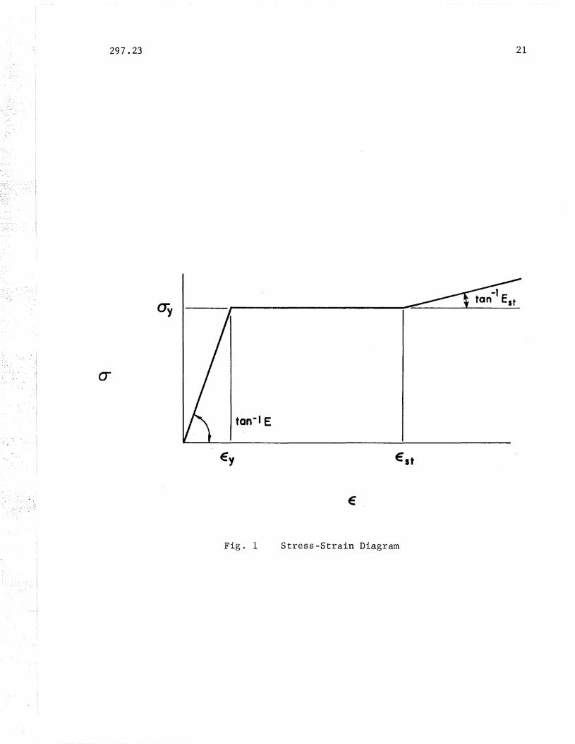
This report presents the results of such an analysis. The structure
is assumed to consist of a material with the stress-strain (a-e) relationship

297.23
shown in Fig. 1. In Fig. 1, the yield stress is denoted as 0 and Ey
-2-
represents the modulus of elasticity. The strain hardening modulus is
denoted by E . The yield strain and the strain at the onset of strainst
hardening are € and e t' respectively. The effect of the materialy s
characteristics is studied by varying the values of E and or e~. Thest s/;".-
results are discussed with the object of determining those factors which
influence the abiltiy of the structure to redistribute bending moment.
The rotary straightening process is performed by cold bending the
member, about its weak axis; back and forth between two sets of heavy
rollers. This process induces residual stresses due to the cold bending,
but more important, it may alter the effective properties of the material.
This process is illustrated analytically and the predicted material
properties are compared with those measured on tensile coupons cut from
rotarized sections. (3)

297.23 -3-
2. ANALYTICAL MODEL
The following section presents the results of an analytical study of
the influence of the stress-strain characteristics on the moment redistri-
bution process. The problem can be stated as follows: in a structure with
one hinge formed, it is desired to increase the moment at potential adjacent
hinge locations while at the same time holding the strains at the original
hinge location to reasonable values and, in addition, ensuring that the
yielded.length at this location does not reach the length required to
precipitate local buckling.
The model chosen for the investigation is the three span beam shown
in Fig. 2a. The member has three equal spans of length, L, and is loaded
with a concentrated load, P, at the. mid-point of the centre span. The
beam is composed of material possessing the characteristics shown by the
0-€ curve of Fig. 1.
If the cross-section is assumed to be composed of two infinitely
thin flanges separated by the depth of the cross-section, d, and the
~ effect of residual stress is neglected, the moment-curvature (M-~)
relationship is that shown in Fig. 3.(6) In this figure M is the full
plastic moment and I is the major axis moment of inertia of the cross-section.
The curvature corres~onding to the attainment of M is 0 and that atp p
the initiation of strain hardening is ~t. The M-0,relationship shown
in Fig. 3 is based on the assumption that instability of the cross-section
does not occur.
The elastic limit curvature distribution along the length of the
member 'is shown in Fig. 2b. As the load is increas~d the moment at the load
point, Me ' exceeds Mp and the yielded zone spread~ from the mid-span section
along the length of the member. The curvature distribution at this stage

297.23 -4-
is shown in Fig. 2c. If the load is increased further, the moments at the
interior supports, M , also exceed M and yielded zones begin to spreads p
from the supports. The corresponding curvature distribution is shown in
Fig. 2d.
The in-plane load-deflection behaviour of the beam will he traced
using the M-0 curve of Fig. 3. The curvature distributions shown in Fig.
2 are non-dimensionalized in such a way that the only numerical data
necessary are the ratios of E/Est
and e Ie. (3) The effect of thest y
material characteristics will be examined by varying these two ratios.
An analysis similar to that presented here was performed by Horne. (7)
An analysis which considered, in addition, the effects of gradual yielding
and residual stress was given by Lay and Smith. (8) Horne considered only
the effect of strain hardening on the equalization of moments at hinge
locations, however, Lay and Smith were able to show that strain hardening
was necessary for moment redistribution. The pr'esent paper shows ·t~~
variation of P, M and M with the variation of E t and € t over thes c· s s
practical range of variation of these properties. The investigation also
shows the variation of the yielded l~ngth at the load point, the load
point deflection and the maxim~m strain over the same range of variation.
of the material characteristics.
While the effect of the material characteristics on moment redistribution,
as evidenced by idealized in-plane behaviour, is important; it has been
observed that the factor which limits the rotation capacity in a braced
beam under moment gradient, is local buckling of the compression flange.(9) (10)
This is due to the large strains existing in the portions of the member
adjacent to the plastic hinges. It has been shown that to delay the
occurrence of local buckling until the optimum rotation capacity has been
obtained, the flange width-to-thickness (bit) ratio must be limited
297 .23
approximately to:
(1)
-5-
where G' is the torsional rigidity in the strain hardening range, given by:
G t 2G
= 1*[4E:tJf(1 1; ~)J (2)
In equation (2), G is the elastic torsional rigidity and t-L is Poisson's
ratio.
For ASTM-A36 or A441 steel, which has not been previously cold worked,
Est is approximately equal to E/45. The limiting bit ratio for A36 material,
with 0y equal to 36 ksi, is 17 (from Eq. (1), and for A441 material,
(Oy = 50 ksi) the ratio is 14. If, however, Est is decreased to a value
of "E/450, which is thought to represent a reasonable upper bound for
material which has been previously yielded during the cold-straightening
process, the corresponding limits on bit are 5~5 and 4.7.
From equations (1) and (2) the effect of the, strain hardeni~g modulus,
Est, on the local buckling resistance of the cross-section can be determined.
In order to ensure reasonable limits for the flange plate geometry in
sections used for plastic design, the value of Est must be as large as
possible. ~his is particularly important with the high strength steels
as an increase in cry will decrease the rang-e of allQwab1e bit ratios.
It will also be shown that a high value of Est increases the efficiency
of the moment redistribution process~

297.23 -~~
3. RESULTS OF ANALYSIS
Computations have been performed for two ratios of E/Est
; 45 and 450;
and three ratios of est/ey ; 1, 12 and 20. The values of Est were chosen to
represent the material characteristics of structural steel under the con-
ditions described above. The values of e tie were chosen to represent as y .
bilinear material (est/ey = 1) and a strain jump which is typical of the
structural steels (e tie = 12 - 20). Throughout the studies in this sections y
the strain hardening range is assumed to be linear.
The plot showing the increase in bending moments with increased load is
'shown in Fig. 4. This graph traces the process of moment redistribution.
The load P, non-dimensionalized as pip is plotted on the vertical axis,p
where P is the load predicted by simple plastic theory (P = 8M IL).P P P
The bending moments at the support and at the l~ad. point, M, are plotted
on the horizontal axis. The moments are'non-dimensionalized as MjM •P
The predictions given by an elastic-plastic analysis are shown as the dashed
lines. (6) As opposed to the idealized elastic-plastic prediction, the
strain hardening properties of the actual material produce an increase in
the load point moment once yielding has been initi'ated at this point. At
piP = 1.0, the load point moment is well above M while that over thep , p
interior support is below MP.The region of interest in Fig. 4 is shown in detail in Figs. '5 and 6.
in Fig. 5 the curves are plotted for E/Est = 45 and three ratios of est/ey ;
1, 12 and 20. In Fig. 6 the curves are plotted for e tie = 12 and E/E t = 45s y . s
and 450. In both cases an increase in the pertinent ratio represents an
increase in the flexibility of the material. From Figs. 5 and 6 it can be
seen tha t the more flexib Ie materials provide more ~f.ficient redistribution

297 .,23 -7-
(3 )
since they reach pip = 1.0 while holding the maximum moment (at the loadp
point) to a smaller value than do their stiffer competitors.
For further load increase, once M has been reached under the load,. p
the zone of large curvatures shown in Fig. 2c must spread from the load
point along the length of the beam. Simultaneously, the moment at this
location, M , increases above M. Once the yielded length, TL, has reachedc p
a sufficient magnitude for a local buckle to form, the response of the
member can no longer be predicted and its useful life is assumed to be
terminated. The variation in TL with an increase in load is thus a
critical property and is plotted in Fig. 7 for material having E/E = 45.at
Fig. 7 plots pIp against the yielded length, iL, non-dimensionalizedp
as'TL/L. As shown in Fig. 7, those materials which are more flexible, that
is, have larger values of e Ie, will develop considerable shorter yieldedst y .
lengths at the simple plastic Ibad level (P = 1.0). Thus, the morep
flexible materials have a larger rotation capacity before the formation lof"
I
a local buckle. The same trend was evident for those materi~ls having
smaller values of Est
For wide flange shapes of compact cross-sections, the wavelength of a
local buckle has been given elsewhere as 21,(11) where
dt Aw 1/4 d21 = 1.42 (--) (--)dw Af
At the initiation of local buckling then
A .=~ = 1.42 (dt) (~)1/4 (~)
'T 1b L dw Af
L
(3)
(4)
In Eqns. (3) and (4), band t denote the flange width and thickness while
d and'w denote the tot~l depth.of the section and the web thickness,

297.23
respectively. The area o~ one flange is given as Af{Af
= bt) and Aw
-8-
represents the web area (A = w(d - 2t».w
For wide flange sections commonly used as beams, the cross-sectional
properties pertinent to local buckling have been tabulated. (12) For these
sections the value of (~~) (~:)1/4 varies from 0.50 to 0.95. Assuming that
10~ ~~ 30, the resulting value of ~lb varies from 0.024 to 0.145. From
Fig. 7, the value of ~lb required to ensure that the load can reach Pp
varies between 0.044 and 0.068. Members having relatively low values ofA
(bt) (w)l/4 b- d - h h- h L t- 1 1 b kl b f h-dw Af
com ~ne w~t ~g d ra ~os may oca uc e e ore reac ~ng
the load predicted by simple plastic theory. This tendency towards pre-
mature local buckling is most evident in_th~ stiffer materials, as seen in
Fig. 7. For the members considered, premature local buckling will rarely
occur. Even in the critical cases, the post-local buckling capacity of the
flange may still enable the member to reach P , however, it is not possbilep
, . (1)at the present time to evaluate this capacity.
From the above considerations, it appears that the more flexible
materials are more readily adaptable for use in plastically designed
structures. Ideally, material .should have a large value of Est to provide
local buckling capacity and a large value of est to provide for efficient
moment redist~ibution 9nd to ensure that the yielded length increases as
slowly as possible. The same conclusion has been reached by.Lay. (13)
However, the above conclusions must he tempered bY.8 consideration of
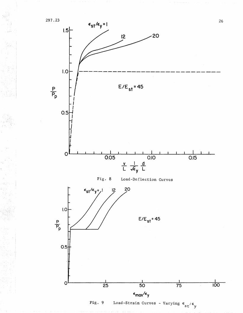
the deflections and strains, which must be of a limited extent. Fig. 8
prese~ts load-deflection curves for the three span beam. The plots are
of pip against the in-plane deflection at the load point, v, non-dimenp
· 1- d v 1 d h ddt th d th f th t- F-s~ona ~ze as L~ L were eno es e ep 0 e cross-sec ~on.. ~g.
8 shows 'that up to the value of pip = 1.0, the deflections are virtuallyp
the same for all materials but beyond this point, the more flexible

297.23
materials exhibit greater deformations at a given load level.
-9-
The progression of the maximum strain, e- at the section adjacentmax'
to-the load point is shown in Figs. 9 and 10. In these figures PIP isP
plotted against the non-dimensionalized maximum strain € Ie. Fig. 9max y
shows the effect of increasing the length of the inelastic plateau,
e Ie For the more flexible materials the maximum strain at a givenst y.
load level is larger. Fig. 10 shows the same tendency for those
materials having decreased values of E t.s .
It has been argued that materials whi~h do not possess strain hardening
11 d · b · h · 1· (8,14,15)properties wi not re ~stri ute moments ~n t e ~ne ~st1C range.
However, all structural metals do exhibit strain hardening to some extent,
and i~ .has been shown that the primary effect 'of the reduced value of Est
is the' . lowered resistance to local buckling. (9)
It appears that the stress-strain characteristics of the structural
steels make them ideally suited for their role in plastic design. The
relatively large values of E (900 ksi for ASTM-A36, 750 ksi for A441)st
result in acceptable limits on flange geometry to prevent premature local
buckling. (1,16) On the other hand the jump in strain at' the yield stress
(approximately 12 e ) provides a large rotation capacity while resu1ting(17)y
in a relatively short yielded length.
The conclusions above are based on a very simple model, however, in a
relative sense, they are valid also for more complex structures. Presently,
plastically designed structures are proportioned to proyide the maximum
possible rotation capacity; it is then assumed that this capacity will be
sufficient to allow the structure to reach P. The next phase of the workp.
remaining would consist of analyzing various structural configurations and
loading conditions to determine whether this optimum rotation capacity is

297.23- -10-
indeed sufficient. A start in this direction could be provided by reanalys
ing the structure considered in this investigation under other loading
and restraint conditions.

297.23 -11-
4 . THE INFLUENCE OF COLD BEND ING
The stress-strain relationship of the material, after rolling and
cooling, has normally been taken as the basis of member behaviour. The
influence of those portions of the member which has been locally yielded
when the member was cold bent (gagged), in order to remove the initial
deformations due to disturbances during the cooling process, was neglected. (7)
, Since the affected areas form only a small proportion of the total length
of the member, the neglect of their action is justified.
In recent years the use of the rotary straightener has increased.
Although it is presently limited to the smaller sections (one approximate
rule of thumb is that the weak axis section modulus be less than 17) it
appea~s'that it will be used in the future for larger sections.
The rotary st~~ightener consists of a series of heavy rolls placed
as shown in Fig. 11 and used to bend the section about the weak axis. The
rolls are arranged so that they bear directly on the flange-to-web junctions
of the member and subject it to two complete cycles of curvature reversal;
rolls No.4 to 7 being the active, or load producing rollers. The member
is fed continuously into the roller arrangement, guided~by rollers No.1,
2 and 3. Roller No.4 is placed in a lowered position relative to the first
three. The difference in elevation may vary from a fraction of an inch to
sev~ral inches, depending on the size of the member, but is enough to produce
a significant permanent set. Roller No.5 ±hen picks up the end of the
member and reverses the direction of the applied curvature. The permanent
set produced by this roller is approximately one-half of that produced by
roller No.4. Rollers No.6 and 7 repeat the process with correspondingly re
duced magnitudes of the applied curvature, and the remainder of the rollers
act primarily as guides. The entire process is one of trial and error. The
297.23 -12-
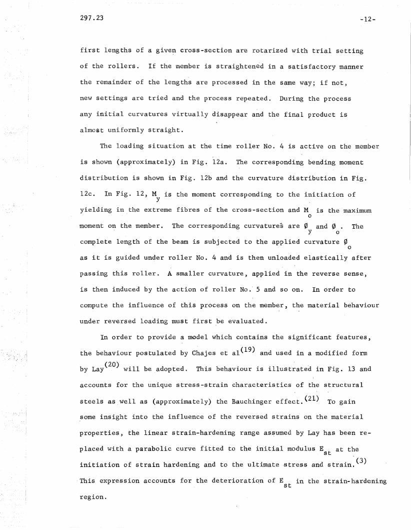
first lengths of a give~ cross-section are rotarized with trial setting
of the rollers. If the member is straightened in a satisfactory manner
the remainder of the lengths are processed in the same way; if not,
new settings are tried and the process repeated. During the process
any initial curvatures virtually disappear and the final product is
almost uniformly straight.
The loading situation at the time roller No. 4 is active on the member
is shown (approximately) in Fig~ l2a. The corresponding bending moment
distribution is shown in Fig. l2b and the curvature distribution in Fig.
12c. In Fig. 12, M is the moment corresponding to the initiation ofy
yielding in the extreme fibres of the cross·-section and M is the maximuma
moment on the member. The corresponding curvatures are 0 and 0. TheY O'
complete length of the beam is subjected to the applied curvature 0o
as it is guided under roller No.4 and is then unloaded ela~tically after
passing this roller. A smaller curvature, applied in the reverse sense,
is then induced by the action of roller No." 5 and so on. In order to
compute the influence of this process on the member, the material behaviour
under reversed loading must first .be evaluated.
In order to provide a model which contains the significant features,
the behaviour postulated by Chajes et a1(19) and used in a modified form
by Lay(20) will be adopted. This behaviour is illustrated in Fig. 13 and
accounts for the unique stress-strain characteristics of the structural
steels as well as (approximately) the Bauchinger effect. (21) To gain
.some insight into the influence of the reversed strains on -the material
properties, the linear strain-hardening range as~umed by Lay has been re-
placed with a parabolic curve fitted to the initial modulus E at thest
initiation of strain hardening and to the ultimate -stress and strain.(3)
,This expression accounts for the deterioratiqn of Est in the 'strain-hardening
region.

297.23 -13-
Using these assumptions it is possible to trace the behaviour of the
material through the strain reversals involved in the rotarizing process.
In-order to do this a sequence of applied curvatures has been selected as
shown in Fig. 14. The initial curvature, 01, is 200 , where 0 is they y
curvature corresponding to the attainment of the yield st~ain at the flange
tips. This is not completely arbitrary as it results in an approximate
value for the deflection under the roller of 1 inch, which seems reasonable.
The curvature is then reversed twice; O2 being equal to l00y
and 03 equal
to 50. The final applied curvature 04 is taken as 1.70 from a trial andy . y
error prosess which will be descirbed below. This value is required to
ensure that the final configuration results in no residual curvature on the
final release of moment'. At this point however, there will be residual
strains in the flanges, which are a result of the inelastic strains induced"
by the reversed bending being superimposed on those which are induced during
cooling. Only the flange plate is considered in the analysis, the web is
relatively unaffected.
To determine the influence of this process on the material an approximate
analysis was used. The flange plate was divided into ten elements as shown
in Fig. 15a and the strains induced" by the applied curvatures computed at
the centroid of each element. For the first applied curvature, 01 , the
strains in each element, e, non~dimensionalizedas e/e , are shown in Fig.y
ISb and the corresponding stresses, cr, in Fig. 15c. The stresses were
calculated on the basis of a flange width of 6 inches and thickness of
0.44 inches and for material having the characteristics of A44l steel.
By integrating the stresses over the cross-section, the applied
moment required to produce a curvature of 200 can be computed. Thisy
process is repeated for the reversals of curvature specified in Fig. 14
297.23 -14-
and for the final elastic. unloading. This 'final unloading should produce
a zero net curvature. for zero applied moment. Thus the final applied curva-
ture, 04, was adjusted to achieve this end.
During the cold bending process, each fibre of the material is assumed
to behave in a manner similar to that depicted in Fig. 13. The cross-section
at the end of the process is in equilibrium and has a negligible residual
,curvature, however, each fibre has at one time been subjected to a long-
itudinal strain that may be in the order of 20 or 30 €. Thus the fibre,y
when strained due to the action of a superimposed external load, may behave
in a bilinear manner with a much reduced~ strain hardening modulus. The
reduction is because of the deterioration of 'the modulus with increased
strain.
The residual stresses which result from the rotarizing process have been
computed and compared with measured values. (3) The trend in the residual
stress distribution induced by the rotarizing procedure can be predicted
although the numerical values do not agree closely due to the uncertainties
in the analysis. (3) Of much greater importance is the effect on the stiff-
ness of the inaterial in the strain-hardening range. Figure l5d shows the
effective strain-hardening modulus, E* plotted as a fraction of the initial, st
modulus 'for the section used as an example. This is the value which would
result from the strain reversals for the process shown in Fig. 14. It is
obvious that the section is less stiff due to the process, but much' more
work remains to be done to determine fully the influence of the rotarizing
pr9cess on the behaviour of plastically designed members.
Further confirmation is provided by the results of tension tests
performed on specimens cut from rotarized members. (2) In addition to
the assumptions made in formulating the rotarizing process and the errors in-

297.23 -15-
duced by the coarse mesh used in the numerical integration,any comparison
with tension test re~ults introduces additional difficulties associated
with the location of the specimen on the cross-section. If the flange
width is small, tension coupon may be cut from the material centered on
the web. In this case the influence of rotarizing may be small. The
other extreme would be the case of a very wide flange with the coupon cut
from the material near the edge. In this case the maximum influence of ro-
tarizing should be observed.
The tests used in this comparison are those performed on specimens cut
from l2B16.5 members.(2) The flange width of this section is 4 inches and
the specimens were milled from coupons located in the flange between the
tip of the flange and the centre line of the web. If the rotarizing sequence
described above is typic~l, then the material near the flange tip has under-
gone a process similar to that traced for element No. 1 in Fig. 14 while
the material near the web remained almost 'completely elastic.
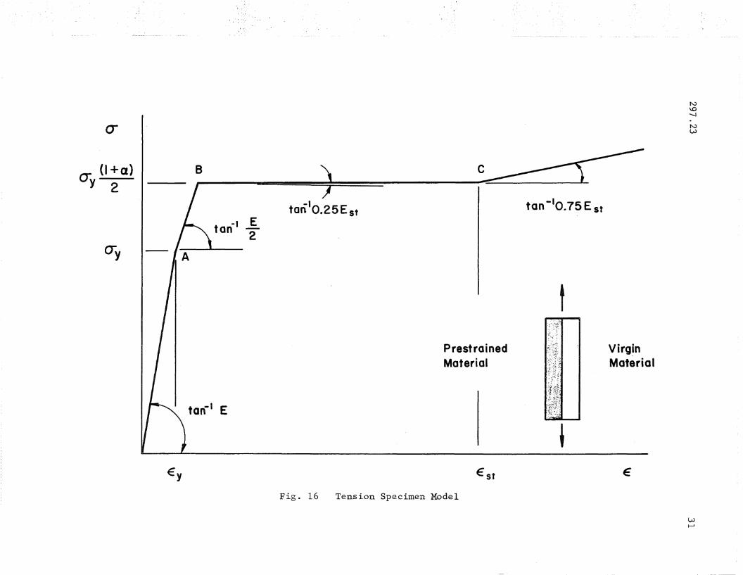
To simulate this case a model is postulated as shown in the inset to
Fig. 16 in which half of the specimen is noted as prestrained and is
assumed to have been subjected to the rotarizing sequence. The other half
is noted as the virgin material ..
As the model is loaded in tension, the behaviour will be ela'tic until
the applied stress reaches the yield stress of the virgin material, 0 •y
This occurs at point A in Fig. 16. At this point the virgin material will
accept further strain with no increase in load, however, the prestrained
material will behave in an elastic manner up to a stress of ao , they
increased yield stress of the prestrained material. Thus the model deforms
from A to B in Fig. 16 with an effective modulus of E/2. At point B the

-16-297.23
increased yield strsss of the prestrained material is reached. To achieve
any further deformation the prestrained material must be subjected to an
increased stress. Due to the reduction in stiffness, as evidenced by Fig. lSd,
this increased stress will be small. At point C the strain-hardening strain
of the .virgin material is reached and further deformation now requires
a distinct increase in stress. The effective modulus is approximately
three-quarters of that for the virgin material.
This is a very crude approximation to the actual behavior. It is sur-
prising therefore to note how well tests on actual tensile specimens
agree with the behavior postulated for the model.(2)
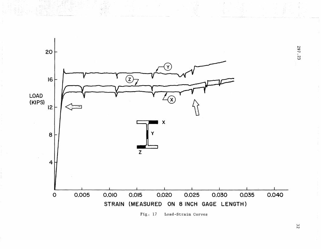
The strain~hardening modulus for 12B16.5 Section was measured for~
eight flange specimens and four web specimens. The original load strain
curves taken for, specimens X, Y, and Z are reproduced in Fig. 17. At
this cross~section all three tensile specimens were loaded into the st~ain
hardening range and the measurements necessary to determine the strain
hardening characteristics were taken.
Specimen Y was cut from the web of the section.and exhibits the sharp
upper yield point and significant strain hardening modulus usually associated
with the structural steels. The modulus computed for this specimen was
680 ksi. On the other hand spcimens X and Z exhibit a rather rounded knee
and a reduced strain-hardening modulus. The areas of interest are
emphasized by the arrows in Fig. 17. Although the rounded knee of 'the
load-strain diagram can be caused by influences other than cold-bending(22)
it is gratifying to note the close agreement between the behavior predicted
by the model used for Fig. 16 and the flange specimens of Fig. 17.
For the other cross-sections used in the investigation o~ Ref,. 2, the
results were similar. 'In each case where comparison was possible the strain
hardening modulus for the web specimen was approximately one third greater

297.23 -17-
than the average for the flange specimens.
In summary, for' sections which have been straightened by rotarizing,
the effective material characteristics (assuming the flanges to exert the
dominant influence) are those of a bilinear material having an effective
value of Est which is decreased from that measured for the virgin material.
The effect of this process is to reduce the lateral and local buckling
capacity of the member. (17)
Tentatively, it appears that the stiffness reduction due to rotarizing
may be in the order of 30%. More detailed information must be obtained,
however, before a firm conclusion can be reached. Studies should be
initiated to define, in a statistical manner, the magnitudes of the curvature
reversals which may be expected during rotarizing. Along with this
data, a knowledge of the behaviour of the material when subjected to large
reversals of strain is essential.' Finally, tests must be performed on
members which have been rotarized in order to provide a check on the
structural behaviour.

297.23 -18,.·
5. SUMMARY AND CONCLUSIONS
This report has examined the influence of the stress-strain
characteristics of the material on moment redistribution in the inelastic
range. In particular the important role played by the strain-hardening
portion of the stress-strain curve has been emphasized.
It may be concluded that a definite strain hardening range is necessary
to ensure moment redistribution. Within certain limits, the ideal material
for a plastically designed structure is that which possesses a large value
of Est to ensure realistic limits on the ,flange plate geometry to preclude
premature local buckling and, in addition, possesses a large value of
est to provide a large rotation capacity for a givenAyielded length.
The structu~al ste~ls seem ideally suited for their role in plastic
design since they possess the desired values of'Est and est. For the
structural steels, local"buckling rather than material failure is the
cause of rotation capacity termination. Fortunately, a high value of Es~
leads to both a large local buckling capacity and an increase in the
efficiency of moment redistribution.
Finally the report has examined the influence of the rotary straighten
ing porcess on the effective material properties. It is concluded that the
severe strain reversals produced by this process foxce the material to,
act as a bilinear material. The result is a marked decrease in the strain
hardening modulus. The analysis of this process is supported by the results
of recent coupon tests taken from rotarized members. No quantitative con
clusions can be drawn, however, it is felt that the effect of the rotary
straightening process explains the apparently reduced deformation capacity
observed in some recent tests. (2) More research must be performed to fully
determine the effect of'rotarizing on structural behaviour.

297.23
6. ACKNOWLEDGEMENTS
-19-
This study is part of a general investigation "Plastic Design in
High Strength. Steel" in progress at Fritz Engineering Laboratory, Lehigh
University. Dr. L. S. Beedle is Director of the Laboratory and Dr. L. W.
Lu is the Project Director. The investigation is sponsored jointly by
the Welding Research Council, and the Department of the Navy, with funds
furnished by the American Institute of Steel Construction, American
Iron and Steel Institute, Naval Ships Systems Command, and Naval Facilities
Engineering Command. The Column Research Council acts in an Advisory
capacity. Mr. S. L. Phillips of the Bethlehem Steel Company provided
information on the rotarizing process.

297.23 -20-
7 • NO:MENCLATURE
E modulus of elasticity
Est ' strain hardening modulus
I
L
M
Mp
Mo
,p
pP
d
v
ey
(J
(Jy
effective strain hardening modulus (after cold bending)
major axis moment of inertia
length
bending moment
plastic moment capacity
maximum moment on member
load
load predicted by simple plastic theory
depth bf cross-section
deflection
proportionality constant (stress)
strain
yield strain (e = IT IE)Y Y
strain at onset of strain hardening
stress
yield stress
curvature
curvature corresponding to attainment of M , assuming ideally elasticp
behaviour (0 = M lEI)P P
curvature at onset of strain hardening
yielded length, that .length over which M exceeds Mp
297.23
tan-I E
21
Ey
Fig. 1
E
Stress-Strain Diagram

297.23
(a )
3L~
·1
22
(b )
(c )
(d )
7PL _,kp----------r 40EI-'fI
-----,-_v--;?/1S:~--~ 3PL 3 "'-40EI=-=r1"lJ
4>st + f 4>p (~-I)sf
4>st + EE epp (~~ -I)sf
¢p
"'Sf
epst+l ¢p (Me _I)Est Mp
Fig. 2 Three Span Beam

297.23
M
Mp
ton- ~ EI
Fig. 3
epst
Moment-Curvature
23

297.23 24
1.2
Moment at0.8 Interior Support
PPp
0.4
M/Mp
1.2
1220
1.00.8
Load-Moment Curves
0.6
Moment atInterior Support
Fig. 4
0.4
E/E sf =45
1.1
0.7
pPp
0.9
M/Mp
Fig. 5 Load-Moment Curves - Varying est/ey

297 • 23 25
1.1
pPp
0.9
0.7
Moment atInterior Support
E/Est =45
450
1.21.00.8
M/Mp
0.6
Load-Moment Curves - Varying E/Est
Fig. 6
0.4
1.5
1.0
pPp
E/E st =45
0.5
O""'-------.a....-------.a....-------...-.-..-----~.040 .080 .120 .160
TL/L
Fig. 7 Load-Yielded Length Curves
297.23
pPp
1.5
1.0
III
0.5 I,I,
26
20
-------------------------------
E/E =4,5sf
OL----L..---L-....L.---L..._L.-.-L----L._..&...-.....L...---I_-L-..........._.a..--......a.....----a._...a..- _
0.05 0.10 0.15v I dL JEy L
Fig. 8 Load-Deflection Curves
pPp
1.0
20
E/E st =45
0.5
Ol---------J.25~-----5L...O-----7.......5-----~IO:-::O~
Fig. 9 Load-Strain Curves - Varying € Iest y

297.23 27
1.5
E/E st =45
1.0
PPp
Est/EY = 12
0.5
oL-----~25~-~--5:::L:O:--------:7::-5----~IO::;:O~
Fig. 10 Load-Strain Curves - Varying E/Est
3 @ 3'-4 =10'-0"
Directionof Travel~...•.:-~
I I I
! 4 J3 1-4" J13 1- 4 I
I'------------~~
Fig. 11 Rotarizing Process

297.2;3
(0)
Roller No.4
-----==--~-===-:::::.:::::::.===~ = ===
1_ 20" J
28
(b) Mp
(c)
Fig. 12 Roller Loading

(J
-IEton st
Fig. 13 Stress-Strain Diagram
E
20-y
N\.0
N\.0""-J.NW

ep4=1.7epy
N\.0
'".NLV
Fig. 14 Sequence of Curvatures
I2
3
4
\ . ~6
7
8
9
··10
(0)
I I I I I
20 10 0 10 20
E/fEr
(b)
I I I I I I I
75 50250 25 5075
(J(KSI)
(c)
I .II
II
II I I
o 0.5 1.0
•Est
Est
(d)
wo
Fig. 15 Integration Process
fJ
fJy
Ey
B
-I .Etan 2
tan-I E
c
-I Etan 0.25 st
PrestrainedMaterial
Est
Fig. 16 Tension Specimen Model
tan -10 .75 E st
t
~
Virg~n
Material
€
N\.0........
NLU
w~
20
16
LOAD(KIPS)
12
8
4
~.--"'_... ~.-_.•~
~
y
z
4:iJx
~
N\.0-...J
NVJ
o 0.005 0.010 0.015 0.020 0.025 0.030 0.035
STRAIN (MEASURED ON 8 INCH GAGE LENGTH-')
Fig. 17 Load-Strain Curves
0.040
WN

297.2~ -33-
8 • REFERENCES
1. Adams, P. F., Lay, M. G. and Galambos, T. V.: Experiments on HighStrength Steel Members, Welding Research Council Bulletin No.110, November 1965.
2. Yura, J. A.: The Strength of Braced Multi-Story Steel Frames, Frit~
Laboratory Report No. 273~28, September 1965.
3. Adams, P. F.: Plastic Design in High Strength Steel, Fritz,Laboratory, Report No. 297.19, Lehigh University, May 1966.
4 .. Beedle', t. S.: Plq.~tic Design of Steel Frames, John Wiley & Sons Inc.,New York, 1958.
5. Lay, M. G. and Galambos, T. V.: The Inelastic Behaviour of Beams UnderMoment Gradient, Fritz Laboratory Report No. 297.12, July.1964. Accepted for publication by ASCE, July 1966.
6. Yang, C. H.: The Plastic Behaviour of Continuous Beams, Thesis'presented to Lehigh University, Bethlehem, Pa. in 1951, inpartial fulfillment of the requirements for the degree ofDoctor of Philosophy.
7. Horne, M. R.: The Effect. of Strain-Hardening on the Equaliz~,tion ofMoments·in the Simple Plastic Theory, British Welding ResearchAssociation FE.l ~ Committee on Load Carrying Capacity of FrameStructures, September 1949.
8. Lay, M. G•. and Smith, P. D.: Role of Strain-Hard.ening in Plastic Design,Proc. ASeE, ·Vol. 91·,. ST3, June 1965.
9. Adams, P. F. and Galambos, T. v.: Discussion of Importance of StrainHardening in Plastic Design, Prac. ASeE, Vol. 92, ST2, April 1966.
10. Lay, M. G. and Galambos, T. v.: The Inelastic 'Behaviour of Beams UnderMoment Gradi~nt, Fritz Laboratory Report No. 297.12, July 1964.,
11. Lay, M. G.: Flange Loc~l Buckling in Wid~-Flange Shapes, Proc. ASCE,Vol. 91, ST6, December 1965.
12. Kerfoot, R. P.: Rotation Capacity of Beams, Fritz Laboratory Report No.297.14, March 1965.
13. L~y, M. G.: A New Approach to Inelastic Structural Design, Prac. ICE,London, England, May 1966.
14. Hrennikoff, A. P.: Theory of Inelastic Bending with Reference to LimitDesign, Trans, ASeE, Vol. 113, p. 213, 1948.
15. Hrennikoff, A. P.: Importance of ~train-Hardening in Plastic Design,Proc. ASeE, Vol. 91,. ·ST4, August 1965.

297.23 -3~-
16. Haaijer, G.: Plate Buckling in the Strain-Hardening Range, Frac.ASCE, Vol. 83, EM2, April 1957.
17. Galambos, T. V.: Beams, Lecture Notes on Plastic Design of MultiStory Frames, Chapter 3, Fritz Laboratory Report, 273.20, LehighUniversity, 1965.
18. Ketter, R. L., Kaminsky, E. L. and Beedle, L. S.: Plastic Deformationof Wide-Flange Beam-Columns, Trans, ASCE, Vol. 120, 1955, p. 1028.
19. Chajes, A., Britvec, S. J. and Winter, G.: Effect of Cold-Straighteningon Structural Sheet Steels, Proc. ASCE, Vol. 89, ST2, April 1963.
20. Lay, M. G.: Discussion of Effect of Large Alternating Strains on SteelBeams, Prac. ASCE, Vol. 91, ST4, August 1965.
21. Freudenthal, A.: The Inelastic Behaviour of Engineering Materials andStructures, John Wiley & Sons, Inc., New York, N. Y., 1950.
22. Beedle, L. S. and Tall, L.: Basic Column Strength, Prac. ASCE, Vol.86, ST7, July 1960.