MatchPort NR Integration Guide - lantronix.com · Recommended PCB Layout _____ 17 Product...
26
Part Number 900-573 Revision B December 2017 MatchPort NR Integration Guide
Transcript of MatchPort NR Integration Guide - lantronix.com · Recommended PCB Layout _____ 17 Product...
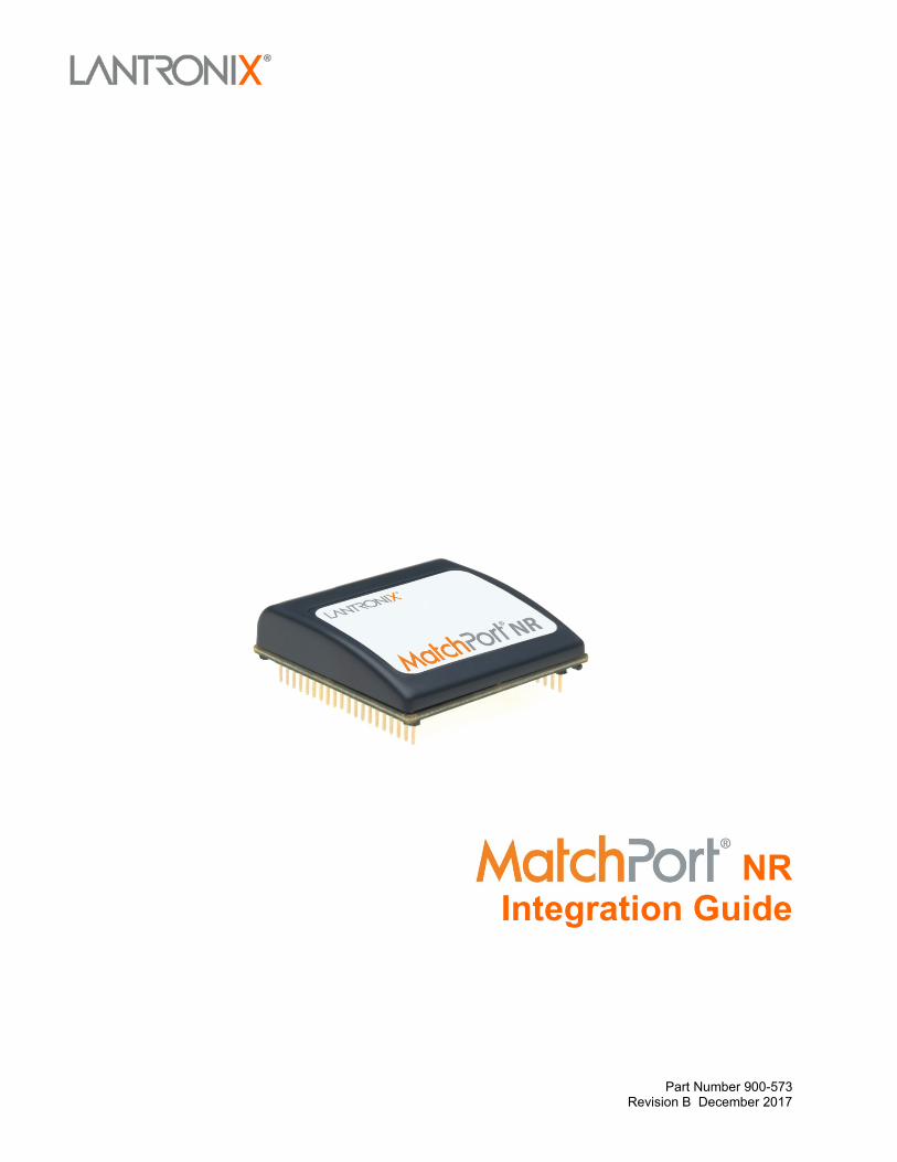
Part Number 900-573 Revision B December 2017
MatchPort NR Integration Guide

MatchPort NR Integration Guide 2
Intellectual Property © 2017 Lantronix. All rights reserved. No part of the contents of this publication may be transmitted or reproduced in any form or by any means without the written permission of Lantronix.
Lantronix and MatchPort NR are trademarks of Lantronix.
Patented: http://patents.lantronix.com; additional patents pending.
Ethernet is a trademark of XEROX Corporation. UNIX is a registered trademark of The Open Group. Windows is a trademark of Microsoft Corp. Netscape is a trademark of Netscape Communications Corporation.
Warranty For details on the Lantronix warranty replacement policy, please go to our Web site at www.lantronix.com/support/warranty.
Contacts Lantronix, Inc. 7535 Irvine Center Drive Suite 100 Irvine, CA 92618, USA
Toll Free: 800-526-8766 Phone: 949-453-3990 Fax: 949-453-3995
Technical Support Online: www.lantronix.com/support
Sales Offices For a current list of our domestic and international sales offices, go to the Lantronix Web site at www.lantronix.com/about/contact
MatchPort NR Integration Guide 3
Disclaimer and Revisions Operation of this equipment in a residential area is likely to cause interference, in which case the user, at his or her own expense, will be required to take whatever measures may be required to correct the interference.
Note: This product has been designed to comply with the limits for a Class B digital device pursuant to Part 15 of FCC Rules. These limits are designed to provide reasonable protection against harmful interference in a residential installation. This equipment generates, uses, and can radiate radio frequency energy, and if not installed and used in accordance with this guide, may cause harmful interference to radio communications.
Changes or modifications to this device not explicitly approved by Lantronix will void the user's authority to operate this device.
Note: With the purchase of MatchPort NR, the OEM agrees to an OEM firmware license agreement that grants the OEM a non-exclusive, royalty-free firmware license to use and distribute the binary firmware image provided, only to the extent necessary to use the MatchPort NR hardware. For further details, please see the MatchPort NR OEM firmware license agreement.
Date Rev. Comments May 2010 A Initial Draft December 2017 B Updated enhanced password information.
For the latest revision of this product document, please check our online documentation at www.lantronix.com/support/documentation.
MatchPort NR Integration Guide 4
Contents List of Figures _______________________________________________________ 5 List of Tables _______________________________________________________ 5
1: Introduction 6 About the Integration Guide ____________________________________________ 6 Additional Documentation______________________________________________ 6
2: Description and Specifications 7 MatchPort NR Overview _______________________________________________ 7 MatchPort NR Block Diagram___________________________________________ 8 PCB Interface _______________________________________________________ 9 Mating Connector ____________________________________________________ 9 Serial Input/Output ___________________________________________________ 9 Sample Layouts for RS-485 Connectivity _________________________________ 11 Ethernet Layout ____________________________________________________ 12 Power, Ground, and Reset Pins ________________________________________ 12 Absolute Maximum Ratings ___________________________________________ 13 Recommended Operating Conditions ___________________________________ 13 Technical Specifications ______________________________________________ 14 Dimensions ________________________________________________________ 15 Recommended PCB Layout ___________________________________________ 17 Product Information Label ____________________________________________ 17
3: Demonstration Kit 18 Contents of the Kit __________________________________________________ 18 Demo Board Description _____________________________________________ 18 Serial Interfaces ____________________________________________________ 18 Power Supply ______________________________________________________ 19 General Control ____________________________________________________ 19 Configuration Switch Bank ____________________________________________ 19 Demo Board Layout _________________________________________________ 21 Demo Board Schematics _____________________________________________ 22
A: Compliance and Warranty Information 26 Compliance Information ______________________________________________ 26 RoHS, REACH and WEEE Compliance Statement _________________________ 26

MatchPort NR Integration Guide 5
List of Figures Figure 2-1. MatchPort NR Block Diagram _________________________________ 8 Figure 2-2. Combined RS-232/422 Transceiver____________________________ 11 Figure 2-3. Separate RS-232/422 Transceivers____________________________ 11 Figure 2-4. Separate RS-422 Transceivers for 2-Wire and 4-Wire Setups _______ 12 Figure 2-5. Side View ________________________________________________ 15 Figure 2-6. Rear View ________________________________________________ 15 Figure 2-7. Top View ________________________________________________ 16 Figure 2-8. Bottom View ______________________________________________ 16 Figure 2-9. PCB Layout (Top View) _____________________________________ 17 Figure 2-10. Product Label ____________________________________________ 17 Figure 3-1. MatchPort NR Demo Board Layout ____________________________ 21 Figure 3-2. Demo Board Schematics ____________________________________ 22
List of Tables Table 2-1. PCB Interface Signals ________________________________________ 9 Table 2-2. RS232 Connections ________________________________________ 10 Table 2-3. JP6 RS422/485 Connections _________________________________ 10 Table 2-4. JP9 RS-422/485 Connections _________________________________ 10 Table 2-5. Power, Ground, and Reset Pins _______________________________ 12 Table 2-6. Absolute Maximum Ratings __________________________________ 13 Table 2-7. Operating Conditions, Serial Ports, & Configurable Pins ____________ 13 Table 2-8. Technical Specifications _____________________________________ 14 Table 3-1. RS-232 Signals ____________________________________________ 19 Table 3-2. RS-485 4-Wire Connector ____________________________________ 19 Table 3-3. Demo Board JP1 Jumper Configuration _________________________ 19 Table 3-4. Demo Board JP7 Jumper Configuration for CON1 _________________ 20 Table 3-5. Demo Board JP8 Jumper Configuration for CON2 _________________ 20 Table 3-6. Demo Board JP5 Jumper Configuration _________________________ 20 Table 3-7. Demo Board Configurable Pin Jumper Configurations ______________ 20
MatchPort NR Integration Guide 6
1: Introduction About the Integration Guide
This guide provides the information needed to integrate the MatchPort NR device server within another product. The intended audiences are the engineers responsible for integrating the MatchPort NR into their product.
Additional Documentation Visit the Lantronix Web site at www.lantronix.com/support/documentation for the following additional documentation.
Document Description MatchPort Demonstration Kit Quick Start Guide
Briefly explains the basics to get the MatchPort NR up and running.
MatchPort User Guide Provides information needed to configure, use, and update the MatchPort NR firmware.
How to Connect a Lantronix Embedded Module to a Wired Ethernet Port
Provides information and details for module layout. (www.lantronix.com/resources/appnotes)
MatchPort NR Integration Guide 7
2: Description and Specifications The MatchPort NR embedded device server is a complete network-enabling solution. MatchPort NR allows Original Equipment Manufacturers (OEMs) to add connectivity to their products by incorporating it onto a circuit board with minimal engineering.
The MatchPort NR functions independently of a PC, providing an integrated solution that combines a processor, memory, a 10/100 Mbps Ethernet transceiver, and two high-speed serial ports into a single compact module. It includes an operating system, an embedded Web server, and a full TCP/IP protocol stack. In addition, the MatchPort NR sends email alerts and supports numerous other network communication protocols, including ARP, UDP, TCP, ICMP, Telnet, AutoIP, DHCP, HTTP and SNMP.
MatchPort NR Overview The MatchPort NR contains Lantronix’s own DSTni controller with 256 Kbytes of internal zero wait state SRAM and 16 Kbytes of boot ROM.
The MatchPort NR also contains the following:
Two 3.3 volt, CMOS level, asynchronous serial interfaces (5 volt tolerant) Support for RS-232 and RS-485 up to 921 Kbps 16 Mbit flash memory 26 (low), 48 (regular), 88 (high) MHz clock 10/100 Mbps Ethernet transceiver (requires external magnetics and RJ45) 8 configurable pins
The MatchPort NR requires +3.3-volt power and is designed to operate within a temperature range of -40ºC to +70ºC.
2:Description and Specifications
MatchPort NR Integration Guide 8
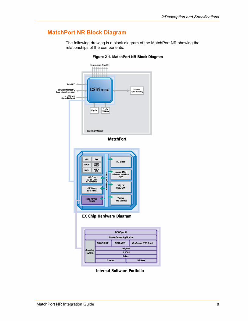
MatchPort NR Block Diagram The following drawing is a block diagram of the MatchPort NR showing the relationships of the components.
Figure 2-1. MatchPort NR Block Diagram
2:Description and Specifications
MatchPort NR Integration Guide 9
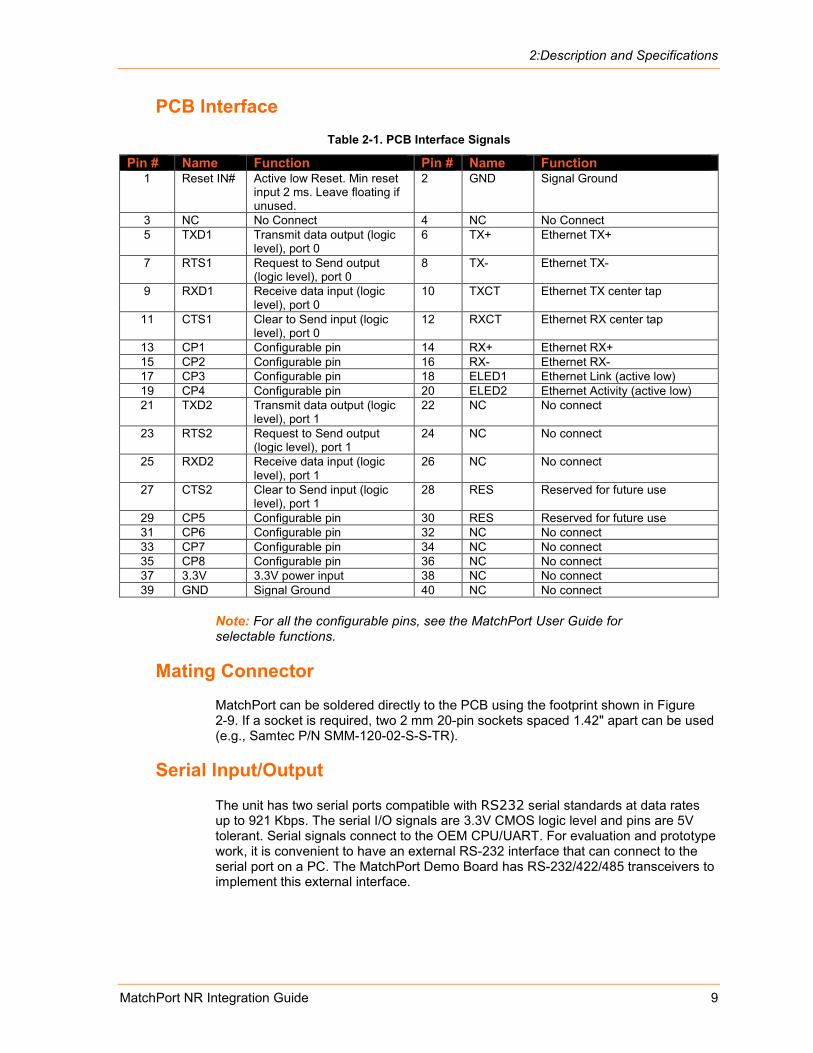
PCB Interface Table 2-1. PCB Interface Signals
Pin # Name Function Pin # Name Function 1 Reset IN# Active low Reset. Min reset
input 2 ms. Leave floating if unused.
2 GND Signal Ground
3 NC No Connect 4 NC No Connect 5 TXD1 Transmit data output (logic
level), port 0 6 TX+ Ethernet TX+
7 RTS1 Request to Send output (logic level), port 0
8 TX- Ethernet TX-
9 RXD1 Receive data input (logic level), port 0
10 TXCT Ethernet TX center tap
11 CTS1 Clear to Send input (logic level), port 0
12 RXCT Ethernet RX center tap
13 CP1 Configurable pin 14 RX+ Ethernet RX+ 15 CP2 Configurable pin 16 RX- Ethernet RX- 17 CP3 Configurable pin 18 ELED1 Ethernet Link (active low) 19 CP4 Configurable pin 20 ELED2 Ethernet Activity (active low) 21 TXD2 Transmit data output (logic
level), port 1 22 NC No connect
23 RTS2 Request to Send output (logic level), port 1
24 NC No connect
25 RXD2 Receive data input (logic level), port 1
26 NC No connect
27 CTS2 Clear to Send input (logic level), port 1
28 RES Reserved for future use
29 CP5 Configurable pin 30 RES Reserved for future use 31 CP6 Configurable pin 32 NC No connect 33 CP7 Configurable pin 34 NC No connect 35 CP8 Configurable pin 36 NC No connect 37 3.3V 3.3V power input 38 NC No connect 39 GND Signal Ground 40 NC No connect
Note: For all the configurable pins, see the MatchPort User Guide for selectable functions.
Mating Connector MatchPort can be soldered directly to the PCB using the footprint shown in Figure 2-9. If a socket is required, two 2 mm 20-pin sockets spaced 1.42" apart can be used (e.g., Samtec P/N SMM-120-02-S-S-TR).
Serial Input/Output
The unit has two serial ports compatible with RS232 serial standards at data rates up to 921 Kbps. The serial I/O signals are 3.3V CMOS logic level and pins are 5V tolerant. Serial signals connect to the OEM CPU/UART. For evaluation and prototype work, it is convenient to have an external RS-232 interface that can connect to the serial port on a PC. The MatchPort Demo Board has RS-232/422/485 transceivers to implement this external interface.
2:Description and Specifications
MatchPort NR Integration Guide 10
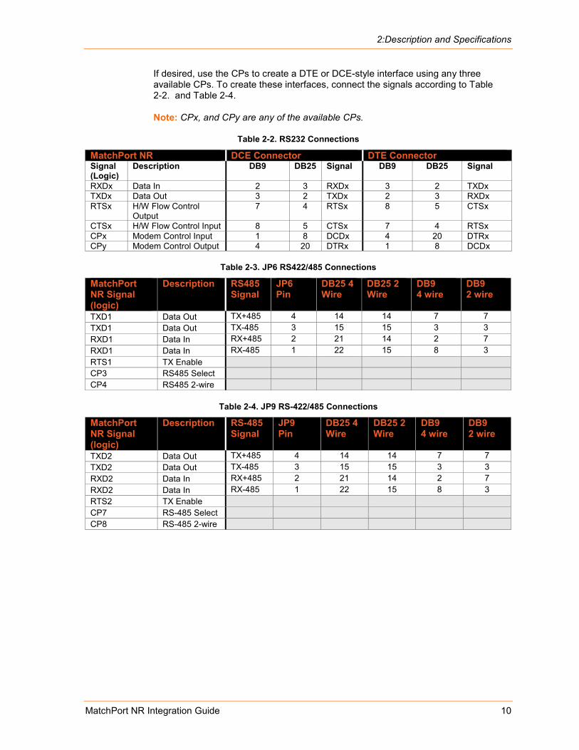
If desired, use the CPs to create a DTE or DCE-style interface using any three available CPs. To create these interfaces, connect the signals according to Table 2-2. and Table 2-4.
Note: CPx, and CPy are any of the available CPs.
Table 2-2. RS232 Connections
MatchPort NR DCE Connector DTE Connector Signal (Logic)
Description DB9 DB25 Signal DB9 DB25 Signal
RXDx Data In 2 3 RXDx 3 2 TXDx TXDx Data Out 3 2 TXDx 2 3 RXDx RTSx H/W Flow Control
Output 7 4 RTSx 8 5 CTSx
CTSx H/W Flow Control Input 8 5 CTSx 7 4 RTSx CPx Modem Control Input 1 8 DCDx 4 20 DTRx CPy Modem Control Output 4 20 DTRx 1 8 DCDx
Table 2-3. JP6 RS422/485 Connections
MatchPort NR Signal (logic)
Description RS485 Signal
JP6 Pin
DB25 4 Wire
DB25 2 Wire
DB9 4 wire
DB9 2 wire
TXD1 Data Out TX+485 4 14 14 7 7 TXD1 Data Out TX-485 3 15 15 3 3 RXD1 Data In RX+485 2 21 14 2 7 RXD1 Data In RX-485 1 22 15 8 3 RTS1 TX Enable CP3 RS485 Select CP4 RS485 2-wire
Table 2-4. JP9 RS-422/485 Connections
MatchPort NR Signal (logic)
Description RS-485 Signal
JP9 Pin
DB25 4 Wire
DB25 2 Wire
DB9 4 wire
DB9 2 wire
TXD2 Data Out TX+485 4 14 14 7 7 TXD2 Data Out TX-485 3 15 15 3 3 RXD2 Data In RX+485 2 21 14 2 7 RXD2 Data In RX-485 1 22 15 8 3 RTS2 TX Enable CP7 RS-485 Select CP8 RS-485 2-wire
2:Description and Specifications
MatchPort NR Integration Guide 11
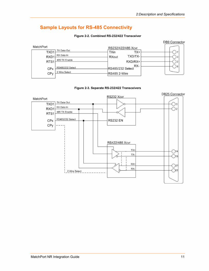
Sample Layouts for RS-485 Connectivity Figure 2-2. Combined RS-232/422 Transceiver
Figure 2-3. Separate RS-232/422 Transceivers
2:Description and Specifications
MatchPort NR Integration Guide 12
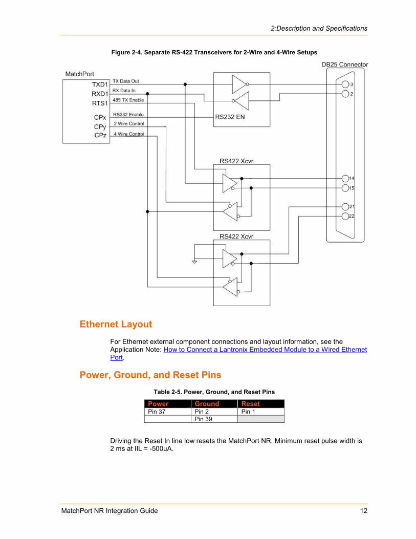
Figure 2-4. Separate RS-422 Transceivers for 2-Wire and 4-Wire Setups
Ethernet Layout For Ethernet external component connections and layout information, see the Application Note: How to Connect a Lantronix Embedded Module to a Wired Ethernet Port.
Power, Ground, and Reset Pins Table 2-5. Power, Ground, and Reset Pins
Power Ground Reset Pin 37 Pin 2 Pin 1 Pin 39
Driving the Reset In line low resets the MatchPort NR. Minimum reset pulse width is 2 ms at IIL = -500uA.

2:Description and Specifications
MatchPort NR Integration Guide 13
Absolute Maximum Ratings Table 2-6. Absolute Maximum Ratings
Parameter Min Max Units Supply Voltage 3.0 3.6 V Input Voltage -0.5 6 V Output Voltage -0.5 6 V Operating Temperature -40 70 ºC Storage Temperature -40 85 ºC
Recommended Operating Conditions The following table illustrates the optimal and recommended operating conditions for the MatchPort NR device.
Table 2-7. Operating Conditions, Serial Ports, & Configurable Pins
Parameter Min Typical Max Units Supply Voltage 3.135 3.3 3.45 V Voltage Ripple 2 % VIL Input Low Voltage* -0.3 0.8 V VIH Input High Voltage* 2 5.5 V II Input Leakage Current* +/- 10 nA +/- 1 µA VOL Output Low Voltage @ IOL max* 0.4 V VOH Output High Voltage @ IOH max* 2.4 V TXDx, RTSx IOL Low Level Output Current @ VOL 0.4V
2.2 3.5 4.3 mA
CP1-CP8 Low Level Output Current @VOL 0.4V
4.4 7.1 8.5 mA
TXDx, RTSx IOH High Level Output Current @ VOH 2.4V
-3.2 -6.4 -10.0 mA
CP1-CP8 IOH High Level Output Current @ VOH 2.4V
-3.2 -6.4 -10.0 mA
* For UART and CP pins
2:Description and Specifications
MatchPort NR Integration Guide 14
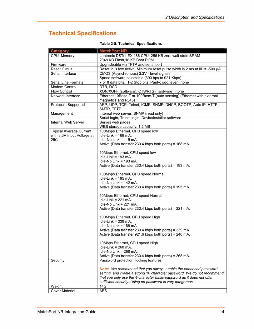
Technical Specifications Table 2-8. Technical Specifications
Category MatchPort NR CPU, Memory Lantronix DSTni-EX 186 CPU, 256 KB zero wait state SRAM
2048 KB Flash,16 KB Boot ROM Firmware Upgradeable via TFTP and serial port Reset Circuit Reset In is low active. Minimum reset pulse width is 2 ms at IIL = -500 µA Serial Interface CMOS (Asynchronous) 3.3V - level signals
Speed software selectable (300 bps to 921 Kbps) Serial Line Formats 7 or 8 data bits, 1-2 Stop bits, Parity: odd, even, none Modem Control DTR, DCD Flow Control XON/XOFF (software), CTS/RTS (hardware), none Network Interface Ethernet 10Base-T or 100Base-T (auto sensing) (Ethernet with external
magnetics and RJ45) Protocols Supported ARP, UDP, TCP, Telnet, ICMP, SNMP, DHCP, BOOTP, Auto IP, HTTP,
SMTP, TFTP Management Internal web server, SNMP (read only)
Serial login, Telnet login, DeviceInstaller software Internal Web Server Serves web pages
WEB storage capacity: 1.2 MB Typical Average Current with 3.3V Input Voltage at 25C
100Mbps Ethernet, CPU speed low Idle-Link = 168 mA. Idle-No Link = 115 mA. Active (Data transfer 230.4 kbps both ports) = 168 mA. 10Mbps Ethernet, CPU speed low Idle-Link = 193 mA. Idle-No Link = 193 mA. Active (Data transfer 230.4 kbps both ports) = 193 mA. 100Mbps Ethernet, CPU speed Normal Idle-Link = 195 mA. Idle-No Link = 142 mA. Active (Data transfer 230.4 kbps both ports) = 195 mA. 10Mbps Ethernet, CPU speed Normal Idle-Link = 221 mA. Idle-No Link = 221 mA. Active (Data transfer 230.4 kbps both ports) = 221 mA. 100Mbps Ethernet, CPU speed High Idle-Link = 239 mA. Idle-No Link = 188 mA. Active (Data transfer 230.4 kbps both ports) = 239 mA. Active (Data transfer 921.6 kbps both ports) = 240 mA. 10Mbps Ethernet, CPU speed High Idle-Link = 268 mA. Idle-No Link = 268 mA. Active (Data transfer 230.4 kbps both ports) = 268 mA.
Security Password protection, locking features Note: We recommend that you always enable the enhanced password setting, and create a strong 16 character password. We do not recommend that you only use the 4-character basic password as it does not offer sufficient security. Using no password is very dangerous.
Weight 14g Cover Material ABS
2:Description and Specifications
MatchPort NR Integration Guide 15
Category MatchPort NR Temperature Operating range: -40°C to +70°C
Storage range: -40°C to +85°C (-40°F to 185°F) Warranty 2-year limited warranty Included Software Windows™ 98/NT/2000/XP based Device Installer configuration software
and Windows™ based Com Port Redirector, DeviceInstaller, and Web-Manager.
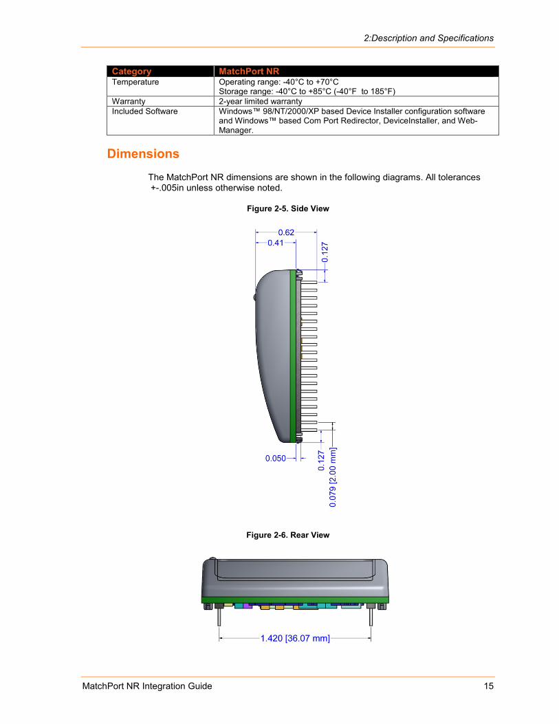
Dimensions The MatchPort NR dimensions are shown in the following diagrams. All tolerances +-.005in unless otherwise noted.
Figure 2-5. Side View
Figure 2-6. Rear View
2:Description and Specifications
MatchPort NR Integration Guide 16
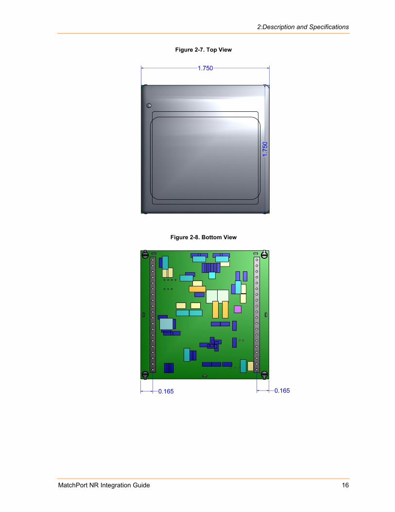
Figure 2-7. Top View
Figure 2-8. Bottom View
2:Description and Specifications
MatchPort NR Integration Guide 17
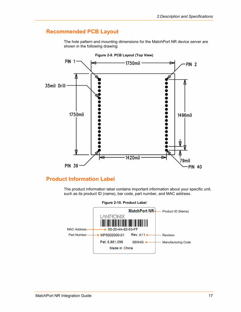
Recommended PCB Layout The hole pattern and mounting dimensions for the MatchPort NR device server are shown in the following drawing:
Figure 2-9. PCB Layout (Top View)
Product Information Label The product information label contains important information about your specific unit, such as its product ID (name), bar code, part number, and MAC address.
Figure 2-10. Product Label
Revision
Manufacturing Code
Part Number
MAC Address
Product ID (Name)
MatchPort NR Integration Guide 18
3: Demonstration Kit The MatchPort NR Demonstration Kit includes everything needed to begin to integrate the MatchPort NR into a given product design.
Contents of the Kit The Demonstration Kit contains the following items:
MatchPort Demo Board 3.6V Power Supply RS-232 cable, DB9F/F, null modem Ethernet cable
Note: You must purchase the MatchPort NR sample separately for use with this Demonstration Kit.
Demo Board Description The MatchPort Demo Board provides a test platform for the Lantronix MatchPort NR device server. It supplies 3.3V power. The MatchPort demo board provides access to all signals to and from the MatchPort NR device server. The demo board has two serial port interfaces (CON1 and CON2). The MatchPort NR demo board also includes an RJ45 connector for use with wired Ethernet.
Serial Interfaces The MatchPort NR serial interface is 3.3V logic level and typically connected to a Universal Asynchronous Receiver/Transmitter (UART). For connection to an external device, the demo board has RS-232/422/485 transceivers. CON1 and CON2 support RS-232/485. Connect to a PC using a null-modem serial cable with 9-pin connectors (F/F).
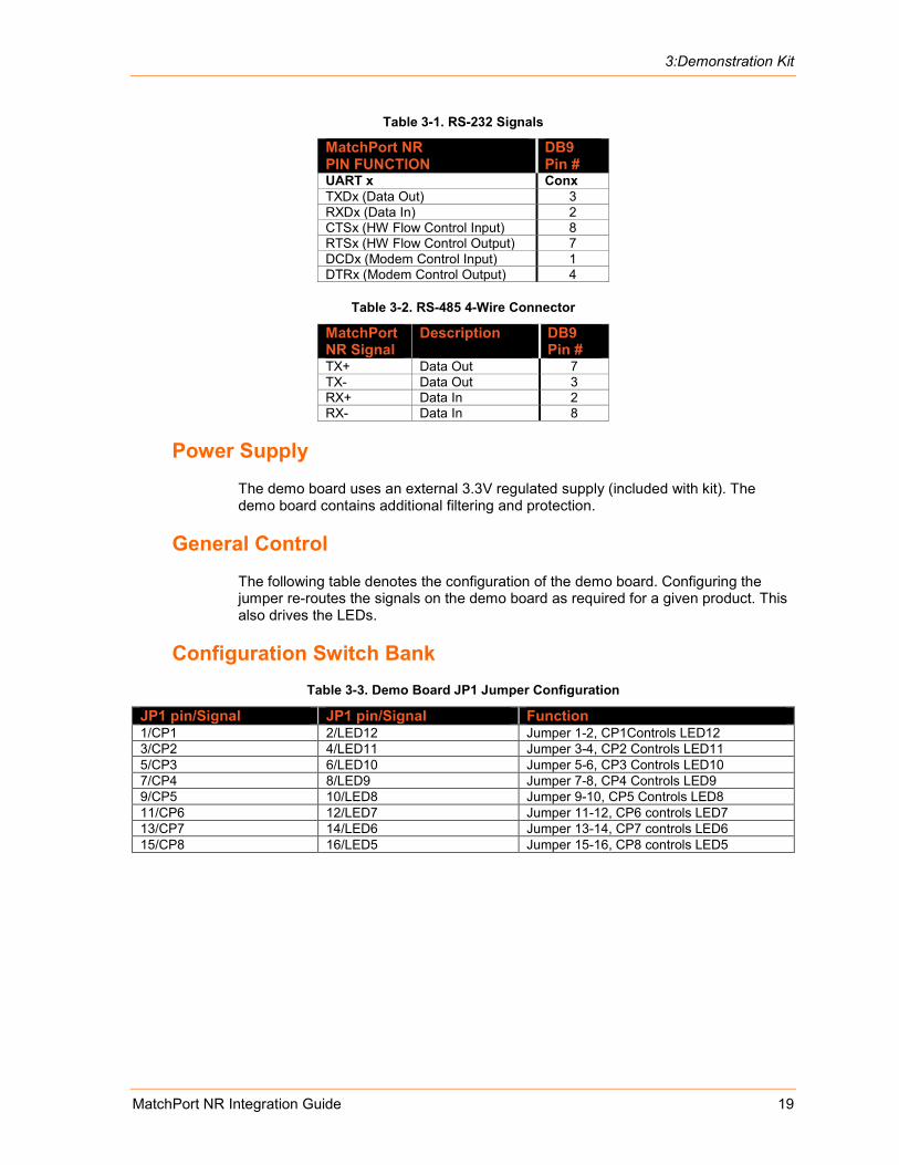
The following table lists the RS-232 signals and corresponding pins on the MatchPort NR. All signals are level-shifted by the RS-232 transceivers.
3:Demonstration Kit
MatchPort NR Integration Guide 19
Table 3-1. RS-232 Signals
MatchPort NR PIN FUNCTION
DB9 Pin #
UART x Conx TXDx (Data Out) 3 RXDx (Data In) 2 CTSx (HW Flow Control Input) 8 RTSx (HW Flow Control Output) 7 DCDx (Modem Control Input) 1 DTRx (Modem Control Output) 4
Table 3-2. RS-485 4-Wire Connector
MatchPort NR Signal
Description
DB9 Pin #
TX+ Data Out 7 TX- Data Out 3 RX+ Data In 2 RX- Data In 8
Power Supply The demo board uses an external 3.3V regulated supply (included with kit). The demo board contains additional filtering and protection.
General Control The following table denotes the configuration of the demo board. Configuring the jumper re-routes the signals on the demo board as required for a given product. This also drives the LEDs.
Configuration Switch Bank Table 3-3. Demo Board JP1 Jumper Configuration
JP1 pin/Signal JP1 pin/Signal Function 1/CP1 2/LED12 Jumper 1-2, CP1Controls LED12 3/CP2 4/LED11 Jumper 3-4, CP2 Controls LED11 5/CP3 6/LED10 Jumper 5-6, CP3 Controls LED10 7/CP4 8/LED9 Jumper 7-8, CP4 Controls LED9 9/CP5 10/LED8 Jumper 9-10, CP5 Controls LED8 11/CP6 12/LED7 Jumper 11-12, CP6 controls LED7 13/CP7 14/LED6 Jumper 13-14, CP7 controls LED6 15/CP8 16/LED5 Jumper 15-16, CP8 controls LED5

3:Demonstration Kit
MatchPort NR Integration Guide 20
Table 3-4. Demo Board JP7 Jumper Configuration for CON1
JP7 pin/Signal JP7 pin/Signal Function 1/TXD1 2/TXA Jumper 1-2, Send TXD to RS-232/485 transceiver. 3/RTS1 4/RTSA Jumper 3-4, Send RTS to RS-232/485 transceiver. In 485 mode
RTS controls transmit enable. 5/CP3 6/SEL4XXA Jumper 5-6, CP3 high selects 485 mode, low 232 mode. 7/RXD1 8/RXA Jumper 7-8, Receive RXD from RS-232/485 transceiver. 9/CTS1 10/CTSA Jumper 9-10, Receive CTS from RS-232 transceiver. 11/CP4 12/HDPX4XXA Jumper 11-12, In 485 mode, CP4 selects full duplex when low,
half duplex when high. 13/CP1 14/DTRA Jumper 13-14, CP1 drives DTR to RS-232 transceiver. 15/CP2 16/DCDA Jumper 15-16, CP2 receives DCD from RS-232 transceiver.
Table 3-5. Demo Board JP8 Jumper Configuration for CON2
JP8 pin/Signal JP8 pin/Signal Function 1/TXD2 2/TXB Jumper 1-2, Send TXD to RS-232/485 transceiver. 3/RTS2 4/RTSB Jumper 3-4, Send RTS to RS-232/485 transceiver. In 485 mode
RTS controls transmit enable. 5/CP7 6/SEL4XXB Jumper 5-6, CP7 high selects 485 mode, low 232 mode. 7/RXD2 8/RXB Jumper 7-8, Receive RXD from RS-232/485 transceiver. 9/CTS2 10/CTSB Jumper 9-10, Receive CTS from RS-232 transceiver. 11/CP8 12/HDPX4XXB Jumper 11-12, In 485 mode, CP8 selects full duplex when low,
half duplex when high. 13/CP5 14/DTRB Jumper 13-14, CP5 drives DTR to RS-232 transceiver. 15/CP6 16/DCDB Jumper 15-16, CP6 receives DCD from RS-232 transceiver.
Table 3-6. Demo Board JP5 Jumper Configuration
Pin/Signal Pin/Signal Function 1/3V3 2/3V3_UUT MatchPort UUT power input jumper for current measurement.
Jumper 1-2 must be installed to provide power to UUT.
Note: If using CPs for any combination of the above demo board configurations, please use the appropriate CP function selection as shown in Table 3-5. If assigning a CP for any function other than the serial port, the jumper for the associated CP pin should be removed from JP1, JP7, or JP8 to avoid conflict with the serial port function.
Table 3-7. Demo Board Configurable Pin Jumper Configurations
Configurable Pin JP1 Function JP7,JP8 Function CP1 LED12 JP7, CON1 DTR CP2 LED11 JP7, CON1 DCD CP3 LED10 JP7, CON1 RS-485/232 Select CP4 LED9 JP7, CON1 RS-485 Duplex Select CP5 LED8 JP8, CON2 DTR CP6 LED7 JP8, CON2 DCD CP7 LED6 JP8, CON2 RS-485/232 Select CP8 LED5 JP8, CON2 RS-485, Duplex Select
3:Demonstration Kit
MatchPort NR Integration Guide 21
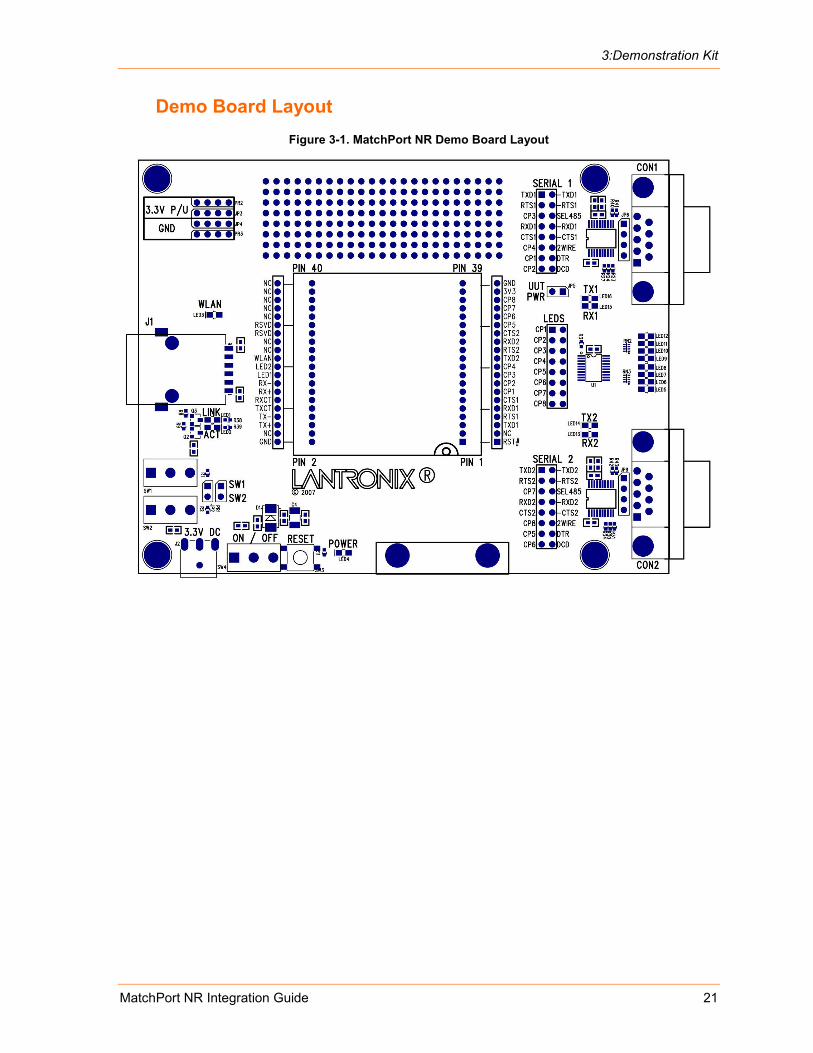
Demo Board Layout Figure 3-1. MatchPort NR Demo Board Layout

3:Demonstration Kit
MatchPort NR Integration Guide 22
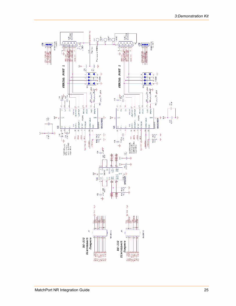
Demo Board Schematics Figure 3-2. Demo Board Schematics

3:Demonstration Kit
MatchPort NR Integration Guide 23

3:Demonstration Kit
MatchPort NR Integration Guide 24
3:Demonstration Kit
MatchPort NR Integration Guide 25

MatchPort NR Integration Guide 26
A: Compliance and Warranty Information Compliance Information
(According to ISO/IEC Guide 22 and EN 45014)
Manufacturer’s Name & Address: Lantronix 167 Technology Drive, Irvine, CA 92618 USA
Declares that the following product:
Product Name Model: MatchPort NR Embedded Device Server
Conforms to the following standards or other normative documents: Safety:
UL 60950-1
CAN/CSA-C22.2 No. 60950-1-03
EN 60950-1:2001, Low Voltage Directive (73/23/EEC)
EMC & Radio:
For purposes of certification, the MatchPort NR was tested as a modular device.
CFR Title 47 FCC Part 15, Subpart B and C, Class B
Industry Canada ICES-003 Issue 4 (2004), Class B
Industry Canada RSS-Gen Issue 1 (2005)
Industry Canada RSS-210 Issue 6 (2005)
EN 301 489-1 v1.6.1 (2006-07), EMC Directive (1999/5/EC)
EN 301 489-17 v.1.2.1 (2002-08), EMC Directive (1999/5/EC)
EN 300 328 v1.7.1 (2006-10), R&TTE Directive (1999/5/EC)
Australia / New Zealand AS/NZS CISPR 22 (2006), Class B
Australia / New Zealand AS/NZS 4771 (2000 + A1:2003)
EN55022: 1998 + A1: 2000 + A2: 2003
EN55024: 1998 + A1: 2001 + A2: 2003
EN61000-3-2: 2000 + A2: 2005
EN61000-3-3: 1995 + A1: 2001
RoHS, REACH and WEEE Compliance Statement Please visit http://www.lantronix.com/legal/rohs/ for Lantronix’s statement about RoHS, REACH and WEEE compliance.