MASTER’S THESIS - University of Oulujultika.oulu.fi/files/nbnfioulu-201711033027.pdf · The...
45
DEGREE PROGRAMME IN ELECTRICAL ENGINEERING MASTER’S THESIS AUTOMATED FUNCTIONAL COVERAGE DRIVEN VERIFICATION WITH UNIVERSAL VERIFICATION METHODOLOGY Author Martti Tiikkainen Supervisor Jukka Lahti Second Examiner Timo Rahkonen Technical Advisor Pekka Kotila March 2017
Transcript of MASTER’S THESIS - University of Oulujultika.oulu.fi/files/nbnfioulu-201711033027.pdf · The...

DEGREE PROGRAMME IN ELECTRICAL ENGINEERING
MASTER’S THESIS
AUTOMATED FUNCTIONAL COVERAGE
DRIVEN VERIFICATION WITH UNIVERSAL
VERIFICATION METHODOLOGY
Author Martti Tiikkainen
Supervisor Jukka Lahti
Second Examiner Timo Rahkonen
Technical Advisor Pekka Kotila
March 2017
Tiikkainen M. (2017) Automated Functional Coverage Driven Verification with
Universal Verification Methodology. University of Oulu, Degree Programme in
Electrical Engineering. Master’s Thesis, 45 p.
ABSTRACT
In this Master’s thesis, the validity of Universal Verification Methodology in
digital design verification is studied. A brief look into the methodology’s history
is taken, and its unique properties and object-oriented features are presented.
Important coverage topics in project planning are discussed, and the two main
types of coverage, code and functional coverage, are explained and the methods
how they are captured are presented.
The practical section of this thesis shows the implementation of a monitoring
environment and an Universal Verification Methodology environment. The
monitoring environment includes class-based components that are used to collect
functional coverage from an existing SystemVerilog test bench. The Universal
Verification Methodology environment uses the same monitoring system, but a
different driving setup to stress the design under test. Coverage and simulation
performance values are extracted and from all test benches and the data is
compared. The results indicate that the Universal Verification Methodology
environment incorporating constrained random stimulus is capable of faster
simulation run times and better code coverage values. The simulation time
measured was up to 26 % faster compared to a module-based environment.
Key words: Universal Verification Methodology, coverage, coverage-driven
verification, methodology comparison.

Tiikkainen M. (2017) Automaattinen toiminnallisen kattavuuden ohjaama
verifiointi universaalilla varmennusmenetelmällä. Oulun yliopisto, sähkötekniikan
koulutusohjelma. Diplomityö, 45 s.
TIIVISTELMÄ
Tässä diplomityössä tutkitaan universaalin varmennusmenetelmän (Universal
Verification Methodology) soveltuvuutta digitaalisten laitteiden verifiointiin.
Työssä tehdään lyhyt katsaus menetelmän historiaan. Lisäksi menetelmän omia
ainutlaatuisia ja olio-pohjaisia ominaisuuksia käydään läpi. Kattavuuteen
liittyviä käsitteitä esitetään projektihallinnan näkökulmasta. Kattavuudesta
käsitellään toiminnallinen ja koodikattavuus, ja tavat, miten näitä molempia
kerätään simulaatioista.
Työn käytännön osuudessa esitetään monitorointiympäristön ja universaalin
varmennusmenetelmän pohjalta tehdyn ympäristön toteutus. Monitorointi-
ympäristössä on luokkapohjaisia komponentteja, joiden avulla kerätään
toiminnallista kattavuutta jo olemassa olevasta testipenkistä. Universaalin
varmennusmenetelmän pohjalta tehdyssä ympäristössä on samojen
monitorointikomponenttien lisäksi testattavan kohteen ohjaamiseen vaadittavia
komponentteja. Eri testipenkeistä kerätään kattavuuteen ja suorituskykyyn
liittyvää dataa vertaamista varten. Tulokset viittaavat siihen, että rajoitettua
satunnaista herätettä hyödykseen käyttävät universaalit varmennusmenetelmä-
ympäristöt pääsevät nopeampiin suoritusaikoihin ja parempiin koodikattavuus-
lukuihin. Simulaation suoritusaikaan saatiin parhaassa tapauksessa jopa 26 %
parannus.
Avainsanat: universaali varmennusmenetelmä, kattavuus, kattavuuden ohjaama
verifiointi, menetelmien vertailu.

TABLE OF CONTENTS
ABSTRACT
TIIVISTELMÄ
TABLE OF CONTENTS
FOREWORD
LIST OF ABBREVIATIONS AND SYMBOLS
1. INTRODUCTION .............................................................................................. 8
2. UNIVERSAL VERIFICATION METHODOLOGY ....................................... 10
2.1. Introduction to UVM ............................................................................... 10
2.2. History ..................................................................................................... 12
2.3. Object-oriented programming ................................................................. 13
2.3.1. Definition of term object-oriented ............................................... 13
2.3.2. Classes and objects ...................................................................... 13
2.3.3. Inheritance ................................................................................... 14
2.3.4. SystemVerilog classes ................................................................. 15
2.3.5. SystemVerilog interfaces ............................................................. 16
2.4. UVM features .......................................................................................... 17
2.4.1. Essential UVCs ............................................................................ 17
2.4.2. Phasing ......................................................................................... 18
2.4.3. Transactions ................................................................................. 18
2.4.4. Factory and configuration database ............................................. 18
2.4.5. Message reporting ........................................................................ 19
2.5. Related work ............................................................................................ 19
3. COVERAGE ..................................................................................................... 20
3.1. Importance of coverage ........................................................................... 20
3.1.1. Coverage planning ....................................................................... 20
3.1.2. Reviewing coverage..................................................................... 21
3.1.3. Verification driven by coverage .................................................. 21
3.2. Code coverage ......................................................................................... 22
3.2.1. Line coverage............................................................................... 22
3.2.2. Statement coverage ...................................................................... 22
3.2.3. Branch coverage .......................................................................... 22
3.2.4. Expression coverage .................................................................... 23
3.2.5. Toggle coverage........................................................................... 23
3.2.6. FSM coverage .............................................................................. 23
3.3. Functional coverage ................................................................................. 23
3.3.1. Covergroups ................................................................................. 24
3.3.2. Assertions .................................................................................... 25
4. UVM MONITORING ENVIRONMENT ........................................................ 27
4.1. Design under test ..................................................................................... 27
4.2. UVM verification components ................................................................ 27

4.2.1. UVM monitors ............................................................................. 28
4.2.2. UVM subscribers ......................................................................... 29
4.3. Parallel test bench .................................................................................... 29
5. COMPLETE UVM ENVIRONMENT ............................................................. 31
5.1. Addition of UVM agents ......................................................................... 31
5.1.1. Drivers and sequencers ................................................................ 31
5.1.2. AHB slave .................................................................................... 32
5.2. Test program ............................................................................................ 32
5.3. Final test bench ........................................................................................ 33
6. RESULTS ......................................................................................................... 35
6.1. Coverage .................................................................................................. 35
6.1.1. Code ............................................................................................. 35
6.1.2. Functional .................................................................................... 36
6.2. Test bench performance .......................................................................... 38
7. DISCUSSION ................................................................................................... 40
8. SUMMARY ...................................................................................................... 42
9. REFERENCES ................................................................................................. 43

FOREWORD
This Master’s thesis was conducted at Nordic Semiconductor ASA Finland. The work
had its ups and downs, and especially the first two months turned out to be quite
stressful. Nevertheless, resolving all problems on the way and completing the thesis
has been a very rewarding and satisfying process.
I would like to thank Nordic Semiconductor ASA Finland for the invaluable
opportunity to work as a thesis worker. I would also like to thank Dr. Jukka Lahti from
the Electronics laboratory and Pekka Kotila from Nordic Semiconductor ASA Finland
for being my supervisors and guiding me during the thesis. In addition to Pekka, I
would like to thank Ercan Kaygusuz from Nordic Semiconductor ASA Finland for the
technical support. Finally, I would like to thank my family and every acquaintance of
mine who has helped me throughout my studies.
Oulu, March 23, 2017
Martti Tiikkainen

LIST OF ABBREVIATIONS AND SYMBOLS
AHB AMBA High-performance Bus
APB Advanced Peripheral Bus
AVM Advanced Verification Methodology
CDV Coverage-Driven Verification
DMA Direct Memory Access
DUT Design Under Test
EDA Electronic Design Automation
eRM e Reuse Methodology
FEC Focused Expression Coverage
IP Intellectual Property
MAC Media Access Control
MECE Mutually Exclusive, Collectively Exhaustive
MDV Metric-Driven Verification
OOA Object-Oriented Approach
OOD Object-Oriented Design
OOP Object-Oriented Programming
OVM Open Verification Methodology
RVM Reuse Verification Methodology
SV SystemVerilog
TLM Transaction-Level Modeling
UCDB Unified Coverage Database
UML Unified Modeling Language
URM Universal Reuse Methodology
UVC UVM Verification Component
UVM Universal Verification Methodology
vAdvisor Verification Advisor
VMM Verification Methodology Manual

1. INTRODUCTION
Verification plays a very big role in the development of digital designs. It is used to
measure if a design has been implemented correctly. Since modern designs, especially
system-on-chips (SoCs), are getting bigger and more complex, planning and
implementing a verification environment becomes a large and demanding task.
Verification can take up to 75% of the total design time and it usually becomes a
bottleneck in project completion [1]. The availability of reusable off-the-shelf
components creates more problems for verification since it allows engineers to
implement more functionality without excessive project development time [2].
This verification problem is tackled by leaning towards more modular and abstract
verification environments that use randomization when generating stimulus. Class-
based environments give modularity and easy access to randomization, and Universal
Verification Methodology (UVM) is the current go-to candidate because it is a well-
known standard and is supported by all major electronic design automation (EDA) tool
vendors [3]. In addition, functional coverage can be used during the simulation to
determine whether to continue with new random values or stop the simulation, or to
modify constraints used in the simulation. Combining these principles one can create
very efficient automated coverage-driven verification (CDV) environments [4].
This thesis studies the advantages and disadvantages of a class-based CDV
environment for verifying intellectual properties (IPs). The objective is to create a
monitoring environment using UVM principles in parallel of an already existing
traditional SystemVerilog (SV) test bench. This monitoring system will enable the
collection of functional coverage from the design under test (DUT). In addition, a
complete UVM verification environment is created based on the original test bench.
The execution sequence of the new UVM environment is the same as the original test
bench, but the UVM environment uses constrained random stimulus and CDV to its
advantage.
The two verification environments are created in order to collect simulation data
regarding code and functional coverage, simulation performance and reusability. The
data from two environments is analyzed and conclusions are made about the
effectiveness of an UVM environment in IP verification. Depending on the results, this
type of verification environment could be used to verify future IPs or SoCs. Because
the implementation of the UVM environment is done keeping modularity in mind,
future reuse would not be as big of a step as creating from scratch.
Chapter 2 introduces the concept of UVM. A brief look is taken into the history of
class-based verification in SV; how UVM became what it is now. The general concepts
of object-oriented programming (OOP) are presented and the common structure of
UVM class hierarchy is explained using these OOP concepts. In addition, this chapter
shows how classes are used in SV verification.
Chapter 3 takes a look into coverage collection and usage in SV. The concepts of
code and functional coverage are presented and different coverage types are presented.
The chapter shows how coverage is captured in simulations and what are SV specific
coverage methods. The chapter also goes through some applications that use the
collected coverage data.
Chapter 4 presents the implementation of the UVM monitoring system that is
injected to the original IP test bench. A short description of the DUT is given. The
chosen points in the design for coverage collection are explained. Finally, the added
9
UVM components are gone through and the test bench used in the simulations is
presented.
In Chapter 5, the finalized complete UVM verification environment is presented.
Additions and changes needed for the environment are gone through. In addition, the
chapter shows problems found when integrating a C-model to a class-based
environment.
Chapter 6 lists the results got from the two environments shown in Chapters 4 and
5. This includes coverage numbers, number of total tests and execution times for
different scenarios.
Chapter 7 presents the final discussion about the topic of this thesis. The results are
analyzed and the usability of class-based CDV environments for future use is
concluded.
Chapter 8 rounds up this thesis. The main chapters and the conclusions made from
the results are summarized.

10
2. UNIVERSAL VERIFICATION METHODOLOGY
This chapter takes a look into Universal Verification Methodology (UVM) as a whole.
Section 2.1 gives a brief overview to UVM verification. Section 2.2 goes through some
of the predecessor methodologies that led to the creation of UVM. Section 2.3 presents
the concepts behind object-oriented programming (OOP) and the OOP practices in
UVM. Lastly, Section 2.4 takes a look into some of the essential UVM-specific
features.
2.1. Introduction to UVM
UVM is a complete methodology that presents the best practices for efficient, reusable
and thorough digital design verification. Reusability is one of UVM’s key
fundamentals and it is achieved by introducing the concept of UVM verification
components (UVCs). These components, as well as other parts of UVM, follow the
principles of OOP. UVM can be used to verify both small and large IP-based designs.
On top of that, UVM is an open-source verification library, and Accelera provides
reference manuals and user guides for the methodology [5][6]. [7, p. 1]
The goal of UVM is to give the designer confidence that their design has been
verified thoroughly in an efficient way, and to point out possible bugs as early as
possible. The best way to get to this type of verification is to use automatic
environments incorporating random stimulus. Figure 1 illustrates a verification flow
that incorporates verification like that [7, p. 3].
VerificationEnvironment
Verificationarchitecture
Stimulus generation,checkers, constraints,
coverage
Simulation,acceleration,
emulation
Write a verification plan
Adjust and addconstraints, checkers and
stimulus sequences
Review coverage
Refine the coveragemodel
Figure 1. A verification planning and execution flow.
11
In addition to automation and random stimulus, few other aspects need to be taken into
account as well when creating these types of environments:
1. The test bench needs to be self-checking to ensure the applied random stimulus
gives correct response from the design under test (DUT).
2. The different generated stimulus needs to be tracked to know what scenarios
have been checked and what not.
3. Control logic should be created between the gathered results and applied
stimulus. This allows steering the generated stimulus towards uncovered
scenarios during the simulation.
The preferred way to track the stimulus and responses with UVM is to use functional
coverage. For example, in SystemVerilog (SV) this can be done by writing
covergroups. UVM provides one of the best frameworks to achieve this type of
versatile and thorough verification. [7, p. 2-3]
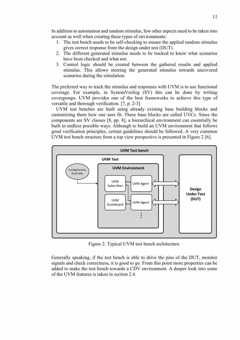
UVM test benches are built using already existing base building blocks and
customizing them how one sees fit. These base blocks are called UVCs. Since the
components are SV classes [8, pp. 8], a hierarchical environment can essentially be
built in endless possible ways. Although to build an UVM environment that follows
good verification principles, certain guidelines should be followed. A very common
UVM test bench structure from a top view perspective is presented in Figure 2 [6].
UVM Test bench
UVM Test
DesignUnder Test
(DUT)
Config/FactoryOverrides
UVM Environment
UVM AgentUVM
Subscriber
UVMScoreboard
UVM Agent
Figure 2. Typical UVM test bench architecture.
Generally speaking, if the test bench is able to drive the pins of the DUT, monitor
signals and check correctness, it is good to go. From this point more properties can be
added to make the test bench towards a CDV environment. A deeper look into some
of the UVM features is taken in section 2.4.
12
2.2. History
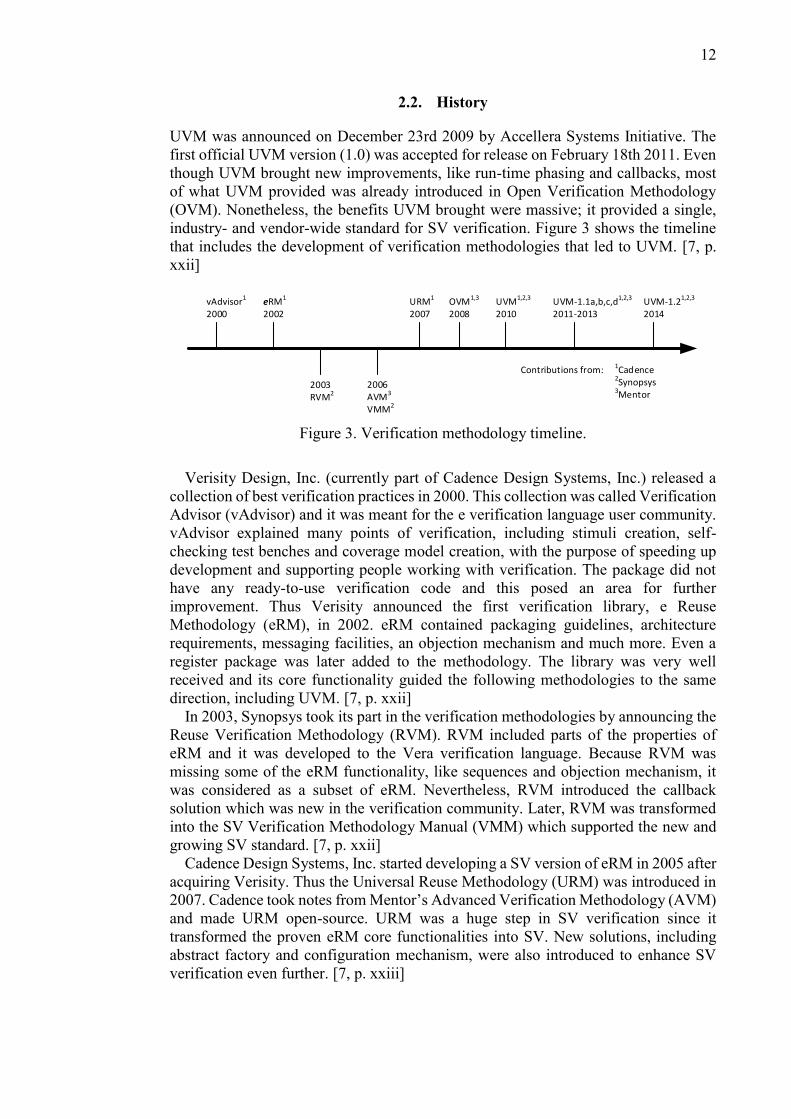
UVM was announced on December 23rd 2009 by Accellera Systems Initiative. The
first official UVM version (1.0) was accepted for release on February 18th 2011. Even
though UVM brought new improvements, like run-time phasing and callbacks, most
of what UVM provided was already introduced in Open Verification Methodology
(OVM). Nonetheless, the benefits UVM brought were massive; it provided a single,
industry- and vendor-wide standard for SV verification. Figure 3 shows the timeline
that includes the development of verification methodologies that led to UVM. [7, p.
xxii]
vAdvisor1
2000eRM1
2002URM1
2007OVM1,3
2008UVM1,2,3
2010UVM-1.1a,b,c,d1,2,3
2011-2013
2003RVM2
2006AVM3
VMM2
Contributions from: 1Cadence2Synopsys3Mentor
UVM-1.21,2,3
2014
Figure 3. Verification methodology timeline.
Verisity Design, Inc. (currently part of Cadence Design Systems, Inc.) released a
collection of best verification practices in 2000. This collection was called Verification
Advisor (vAdvisor) and it was meant for the e verification language user community.
vAdvisor explained many points of verification, including stimuli creation, self-
checking test benches and coverage model creation, with the purpose of speeding up
development and supporting people working with verification. The package did not
have any ready-to-use verification code and this posed an area for further
improvement. Thus Verisity announced the first verification library, e Reuse
Methodology (eRM), in 2002. eRM contained packaging guidelines, architecture
requirements, messaging facilities, an objection mechanism and much more. Even a
register package was later added to the methodology. The library was very well
received and its core functionality guided the following methodologies to the same
direction, including UVM. [7, p. xxii]
In 2003, Synopsys took its part in the verification methodologies by announcing the
Reuse Verification Methodology (RVM). RVM included parts of the properties of
eRM and it was developed to the Vera verification language. Because RVM was
missing some of the eRM functionality, like sequences and objection mechanism, it
was considered as a subset of eRM. Nevertheless, RVM introduced the callback
solution which was new in the verification community. Later, RVM was transformed
into the SV Verification Methodology Manual (VMM) which supported the new and
growing SV standard. [7, p. xxii]
Cadence Design Systems, Inc. started developing a SV version of eRM in 2005 after
acquiring Verisity. Thus the Universal Reuse Methodology (URM) was introduced in
2007. Cadence took notes from Mentor’s Advanced Verification Methodology (AVM)
and made URM open-source. URM was a huge step in SV verification since it
transformed the proven eRM core functionalities into SV. New solutions, including
abstract factory and configuration mechanism, were also introduced to enhance SV
verification even further. [7, p. xxiii]

13
In 2008, Mentor and Cadence worked together and introduced OVM. Many of the
URM properties were used in OVM because of URM’s proven high-level
methodology infrastructure. OVM was once again a huge step in verification
methodologies since it was the first multi-vendor solution that could be used with more
than one vendor simulator. This led OVM to be the methodology of choice for people
who wanted their environments to be simulator-neutral. In addition, OVM spawned
larger scale community sites for questions and idea sharing. [7, p. xxiii]
In 2010, the development of UVM was started and the OVM version 2.1.1 was
chosen as the base. Soon after the first release of UVM it became the go-to verification
methodology. UVM removed all vendor specific gimmicks since it is supported and
tested with all major EDA tool vendor simulators. UVM versions 1.1a, 1.1b, 1.1c and
1.1d have improved the quality of the methodology while maintaining the APIs of the
standard. The latest version (1.2) remains a bit controversial since verification experts
disagree with some of the new features [9]. Thus 1.1d is currently the most used
methodology in SV verification, at least until 1.2 is more mature. [7, p. xxiii]
2.3. Object-oriented programming
This section explains few of the most important features of object-oriented
programming (OOP). This includes the common idea behind OOP, classes and objects,
and inheritance. SV classes and interfaces are also gone through separately. Even
though the OOP principles are explained from a general object-oriented (OO) point of
view, the same properties are present in UVM.
2.3.1. Definition of term object-oriented
From a programming point of view, object-oriented means that the software
components are organized as a selection of discrete objects that include data and
possible action over it [10, pp. 1-1]. The idea is to create more abstract, configurable
and reusable building blocks for programming. The user does not need to know all the
details what is going on under the hood. Only the needed attributes and commands
from the top view perspective can be given to the user and the more detailed
implementation remains hidden. With this kind of object-oriented approach (OOA),
the tools used in programming appear much more like how humans think of objects
instead of machine-like parameters and instructions. For example, in a UVM
verification environment it is not necessary to know how a driver controls an APB bus;
the availability of a write and read task is sufficient.
2.3.2. Classes and objects
For OOP, information hiding and abstraction are one of the key points for the
foundation of a clear design [11]. Both of these are introduced with classes. A class is
a derived data-type, similar to a structure. Instead of grouping together only elements
of different data-types like a structure, a class can also include functions [10, pp. 10-
1]. Therefore, a class can have attributes to store data and methods to implement
functionality. Figure 4 illustrates a Unified Modeling Language (UML) class diagram

14
used in object-oriented design (OOD) [12, p. 6]. UVM hierarchies including similar
class blocks can be extracted from UVM simulations.
ClassName
string attribute_name
int attribute_id
int attribute_data
string function_getName()
void function_setData(int d)
+
+
-
+
+
Figure 4. UML diagram presentation of a class. Diagram includes the class name,
attributes, methods and their types.
Attributes and methods can be declared as public, protected or private (local in SV).
This can be used to make some functionalities of the class unavailable to the outside
world, adding information hiding. In Figure 4 this can be seen as plus and minus signs,
plus meaning public and minus private.
Object is an instance of a defined class. It is important to remember that defining a
class is not enough to use its properties. Only after an object is created from a class
can the class attributes and methods be accessed through the object. Any number of
objects can be created from a class and thus they can have different identity, state and
behavior even though they are all derived from the same class [13, pp. 5]. When
creating an object, it allocates the needed amount of memory. It is required to keep
track of created objects to make sure they are destructed and the allocated memory is
freed. Fortunately, in SV this is handled very well automatically and the user does not
need to worry about memory leaks [8, pp. 8-29]. [14, pp 3-1]
2.3.3. Inheritance
Alongside with the concept of classes and objects, inheritance is one the most powerful
features of OOP. In OOP, the process of creating a new derived class from an already
existing class (base class) is called inheritance. This process is also known as class
extension. The extended class inherits all public and protected attributes and methods
from the base class. Inheritance is visualized in Figure 5 by extending the example
class presented in Figure 4 [13, pp. 8].

15
ClassName
string attribute_name
int attribute_id
int attribute_data
string function_getName()
void function_setData(int d)
+
+
-
+
+
ExtendedClassName
int attribute_addr
int function_getAddr()
+
+
Object made fromExtendedClassName:
ObjectName
string attribute_name
int attribute_data
+
+
int attribute_addr+
string function_getName()
void function_setData(int d)
+
+
int function_getAddr()+
Figure 5. Inheritance presented in UML class diagram form with an object example.
As it can be seen in Figure 5, the example object ObjectName created from the
extended class has access to all public attributes and methods from the classes
ClassName and ExtendedClassName. The base class remains completely unchanged
with extension. [10, pp. 12]
The advantage got from inheritance is reusability. If more functionality is needed, it
can be added with extension instead of changing already working and verified code.
This allows creating new code from another company’s or person’s existing code
without modifying the source [10, pp. 12]. In UVM, the idea is to extend existing UVM
components and modify them to fit to the verification environment. The UVM base
classes bring many positive properties to the verification environment like automatic
phasing and transaction-level communication models. In addition, if a common class-
based verification environment is created for a larger project, all subtests can extend
the common environment to make more targeted tests.
2.3.4. SystemVerilog classes
For SV classes, all OOP principles mentioned in the previous sections are present. In
addition, the usage of tasks [8, pp. 13] is also possible alongside with functions in SV
classes. Tasks need to be used if time-consuming statements are desired inside classes.
SV classes also have properties, like rand type definition and constraints, that are
essential with verification environments using random stimulus. The following
paragraphs take a deeper look into these two features.
A very powerful feature of SV classes is that the attributes can be defined with a
randomize type (rand) [8, pp. 8-12]. This makes randomization of parameters very
efficient because all rand defined attributes in the same hierarchy level can be assigned

16
a random legal value with a single function call. The randomization can also be
targeted to single attributes. An example SV class and its randomization is presented
in Figure 6 below.
class class_example; // attributes protected int id; rand int data; rand int addr; rand bit readwrite; // constructor, methods, etc. endclass
Class definition: Test program:
class_example cl1; int check; initial begin cl1 = new(); check = cl1.randomize(); assert (check); else $error(”rand failed!”); end
Figure 6. Class instantiation and randomization in SV.
In Figure 6, an instance cl1 of the class class_example is created with the new()
constructor and the randomization is done with cl1.randomize(). The randomize
method returns an integer that indicates whether the randomization was successful or
not. The integer check and an assertion is used to report any errors regarding the
randomization. In this example, the randomize call will change the values of data, addr
and readwrite attributes to random integer and bit values. Integer id remains
unchanged since it does not have a rand type defined.
The legal range of values can be changed using SV constraints [8, pp. 18-5].
Constraints can be used to ensure that the randomized values will be reasonable and
will actually stress the DUT. For example, without constraints the attribute data in
Figure 6 will be randomized to any possible value of a 32-bit signed integer. A
constraint could be added to limit the result of randomization into a small set of values.
Inside these values, weight factor can also be used to make some values more likely to
be the result of the randomization than ones with smaller weight.
2.3.5. SystemVerilog interfaces
In SV, interfaces encapsulate the communication between blocks, allowing a smooth
migration from abstract system-level design through successive refinement down to
lower level register-transfer and structural views of the design. At its lowest level, an
interface is a named bundle of nets and variables. In addition, SV interfaces can include
functionality in the form of SV tasks and functions, and module ports (modports) to
restrict interface access by declaring the direction of the interface signals. Using
module ports is an useful way to create different types of components, like masters
and slaves, that use the same interface signals, but with different signal directions. [8,
pp. 25]
Interfaces are not limited to class-based SV applications, but they are essential when
giving SV classes access to specific signals found in the DUT. This is done by giving
the class a reference to the original interface. The reference is given as a virtual
interface. The component using the virtual interface can access any signal, task or

17
function it is permitted to use through the virtual interface. Using virtual interfaces
adds abstraction and separates the test environment from the actual signals in the
design, promoting code reuse. [8, pp. 25-9]
2.4. UVM features
This section shows the most important UVM components found in a typical UVM test
bench. In addition, some of the essential UVM features are gone through. These
features consist of simulation phasing, data transactions, factory registration,
configuration and information reporting. To get the most out of UVM verification,
these properties should be capitalized in the environment.
2.4.1. Essential UVCs
Even though UVM environments can be built in multiple possible ways and allow high
amount of customization, nearly all of them include the most common UVCs that are
needed for test bench creation and DUT interaction. Specific components should be
used for their purposes only to ensure the code remains readable and follows the
general verification guidelines. The most common UVCs are described in Table 1
below [6, pp. 1-1].
Table 1. List of common UVM verification components
UVM component Description
Test The UVM Test is the top-level component in the UVM test
bench. The UVM Test typically performs three main functions:
instantiates the top-level environment, configures the environ-
ment and applies stimulus to the DUT with UVM Sequences.
Environment The UVM Environment groups together other components that
are interrelated. These components include UVM Agents,
Subscribers, Scoreboards, or even other Environments.
Subscriber The UVM Subscriber’s function is to check correct behavior
and collect functional coverage. A UVM Scoreboard is a
similar component to the UVM Subscriber.
Agent The UVM Agent contains components that are dealing with a
specific DUT interface. A typical UVM Agent includes a UVM
Sequencer, Driver and Monitor.
Monitor The UVM Monitor samples the DUT interface and stores the
information to transactions, which are sent out to the rest of the
UVM test bench for further analysis.
Driver The UVM Driver receives individual transactions and trans-
forms them into DUT pin wiggles.
Sequencer The UVM Sequencer serves as an arbiter for controlling
transaction flow to a UVM Driver. The transaction flow is
determined by UVM Sequences.
Sequence UVM Sequences are objects that contain behavior for gene-
rating stimulus.

18
2.4.2. Phasing
UVM has a set of automated function and task calls during UVM simulations that all
UVCs execute at the same time. These function and task calls create the phasing
mechanism of UVM. All UVCs are always synchronized with respect to these phases
[15]. Thus if an extended UVM class has a specific named function or task declared,
it will be executed automatically when the UVM simulation enters that specific phase.
The UVM class library includes common phases and they can be found in the UVM
class reference manual [5, pp. 9-6]. From these phases, the build, connect and run
phase are used to set up the environment and run the simulation. Build phase is used
to create all subcomponents (objects) for the class and to assign needed virtual
interfaces. It is good to understand that the UVM environment does not exist until all
build phase functions have been run. In connect phase, all transaction level modeling
(TLM) connections are made between the required UVCs. Only after the connect
phase is the environment complete and ready to be used in simulations. Lastly, all
simulations are done in the run phase, or they can be divided into subsections of the
run phase if desired. [5, pp. 9-6]
2.4.3. Transactions
Transactions in UVM are basic data objects that represent data movement between
different UVCs [15]. They are used to represent communication at a more abstract
level. Because transactions are SV classes as well, all necessary information can be
stored in the attributes of the transaction class. It is up to the driver to transform
transactions into pin wiggles the DUT can understand. With the help of a UVM
sequencer [5, pp. 19-3], creating activity becomes a very simple task. Transactions
eliminate the need to know all the details happening at pin level and the focus can go
towards creating more scenarios. In addition, UVM sequences can be used to model
multiple consecutive transactions. [5, pp. 5-3]
2.4.4. Factory and configuration database
The UVM factory mechanism is an implementation of the factory pattern found in
OOP literature [15]. The factory can be used to create UVM objects and components
if the type of the created class is registered to the factory. User-defined components
and objects are usually registered to the factory with UVM macros. If a new object or
component is requested to be created from the factory, the factory will create an object
according to its configuration. A registered class can be overridden with another class
that extends the original. This allows replacing components in the verification
hierarchy with custom ones, and it can even be done during the simulation. [5, pp. 8-
2]
The UVM configuration database functions as a centralized database where type
specific information can be stored and retrieved [5, pp. 10]. The database also supports
hierarchical configuration; information can be stored for specific components only or
multiple components under one hierarchy level. The latest write to the database will
always overwrite previous existing configurations for the selected level of hierarchy.
Even though the database can be used for multiple different purposes, it has one
especially important application: to configure the test bench as it is constructed [16].

19
All references to top module-level components need to be transferred to the UVM class
environment through the database. This is how the UVM agents get their accesses to
the interfaces connected to the DUT. In addition, the whole behavior or structure of
the UVM test bench can be changed according to the setup values fetched from the
configuration database before building the UVM environment.
2.4.5. Message reporting
UVM also has a built in message reporting system. Available message types are info,
warning, error and fatal. The system enables reporting messages with different severity
levels and keeps track of messages with the same ID. In the end of the simulation,
UVM gives a recap of all different sources and the number of reports from every
source. Visibility of different severity level messages can be changed by UVM
simulation parameters. Custom prints can be also added to the UVM info type
messages. The common way to use the system is through the UVM report macros,
which makes writing the reporting code more user friendly [5, pp. 21-1]. [5, pp. 6]
2.5. Related work
UVM has been in the spotlight in RTL verification for the past few years and
verification engineers have been eager to put its praised features to use. Francesconi J.
et al. successfully used UVM in the building of two RTL verification environments,
and experienced increased productivity when reusing the UVM verification
components from the first environment [17]. Zhaohui H. et al. studied the inte-gration
of IP-level UVM test benches and test cases to SoC-level, which also showed a high
amount of possible reuse while saving resources needed for the integration [18].
The two main points used for UVM validation in this thesis are coverage results got
with CDV and simulation performance statistics. The measurement and analysis of
functional verification and coverage, including CDV, has been studied by Piziali A.
[19]. In his work, Piziali presents methods and guidelines for functional coverage
related applications. Söderlund T. and Kärenlampi L. studied test bench performances
in their theses [20][21]. Kärenlampi used profiling for accurate performance results in
his work, and Söderlund implemented an UVM environment based on a legacy test
bench and compared these two.
20
3. COVERAGE
This chapter introduces the concepts of functional and code coverage in
SystemVerilog (SV); how they are collected and what is done with them. Section 3.1
starts with the reasons, phases and CDV. Sections 3.2 and 3.3 list the parts that make
up code and functional coverage and go through how they are captured.
3.1. Importance of coverage
In verification, it is not practical to run test cases without any indicator telling when
all required functionalities have been checked. Data got from code and functional
coverage can be used to address this verification problem. Coverage models can be
manually written to fit the needs of the design. However, even though the tools
available nowadays make the verification environment creation process less painful, it
is very important to think about all verification related problems from a coverage point
of view [22]. This kind of approach is essential when creating a coverage collection
infrastructure.
Planning and implementing a thorough coverage environment requires more time
and effort but when done correctly, it pays itself out in the end [23, pp. 1-4]. A well-
written coverage environment saves many hours of working time spent on manual
checking for correctness and verification status. In addition, giving a thought to
functional coverage before design implementation can help to bring out key points in
the design specification. This can make the actual implementation process easier and
reduce verification needs later in the project.
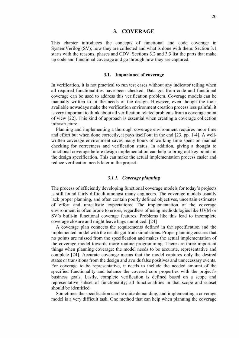
3.1.1. Coverage planning
The process of efficiently developing functional coverage models for today’s projects
is still found fairly difficult amongst many engineers. The coverage models usually
lack proper planning, and often contain poorly defined objectives, uncertain estimates
of effort and unrealistic expectations. The implementation of the coverage
environment is often prone to errors, regardless of using methodologies like UVM or
SV’s built-in functional coverage features. Problems like this lead to incomplete
coverage closure and might leave bugs unnoticed. [24]
A coverage plan connects the requirements defined in the specification and the
implemented model with the results got from simulations. Proper planning ensures that
no points are missed from the specification and makes the actual implementation of
the coverage model towards more routine programming. There are three important
things when planning coverage: the model needs to be accurate, representative and
complete [24]. Accurate coverage means that the model captures only the desired
states or transitions from the design and avoids false positives and unnecessary events.
For coverage to be representative, it needs to include the needed amount of the
specified functionality and balance the covered core properties with the project’s
business goals. Lastly, complete verification is defined based on a scope and
representative subset of functionality; all functionalities in that scope and subset
should be identified.
Sometimes the specification can be quite demanding, and implementing a coverage
model is a very difficult task. One method that can help when planning the coverage

21
model for hard-to-implement properties is the Mutually Exclusive, Collectively
Exhaustive (MECE) approach [25]. Using the MECE approach, a coverage
requirement can be divided into multiple definitions. All definitions are a subset of the
full requirement and independent from each other, and together they form a coverage
model for the original requirement. The MECE approach is illustrated in Figure 7 [24].
Feature /Scenario
Definition 2
Definition 3
Definition 1
CECollectivelyExhaustive
Together, definitions fullydescribe the area to be covered
MEMutuallyExclusive
Definitions areindependentfrom each other
Figure 7. MECE approach for coverage collection.
3.1.2. Reviewing coverage
A single coverage metric is not enough to get a complete coverage closure. Also, just
looking at the coverage numbers got from the simulations is not sufficient; depending
on the size of the project, a significant amount of processing and reviewing can be
required to determine the actual coverage status. For example, having code coverage
of 100 % does not necessarily mean that the DUT has been completely verified. Some
functionalities might be missing and the 100 % comes from a subset of the whole
requirement [26]. On the other hand, complete functional coverage but lacking code
coverage might suggest that the coverage model is faulty, or the implementation has
redundant, unnecessary properties that were never specified.
This is why carefully reviewing coverage results is important, even with a flawless
coverage plan. It helps to bring out the lacking aspects of the design or the coverage
model and understand them better, and guide engineers towards what should be
verified next. In addition, reviewing is a good time to make sure everyone related to
the particular design is on the same information level. Just as with verification
planning, frequent reviewing ensures on-time project completion with zero bugs
unnoticed.
3.1.3. Verification driven by coverage
One application for coverage data is to use the data to automate or drive the verification
during the simulation. The approach where coverage is used as the engine that drives
the verification flow is called coverage-driven verification (CDV) [27]. With CDV,
22
the environment can be made automatic by using coverage as the indicator whether to
continue the simulation or not. On the other hand, coverage can also be used to tweak
the constraints that affect the randomized parameters during stimulus generation. With
a proper algorithm, changing the constraints according to the coverage results can be
very beneficial for reaching complete coverage closure [4]. Both of these scenarios
require the use of manually declared functional coverage models. In SV, the
recommended way to do this is to use covergroups and its built in features (see Section
3.3.1.).
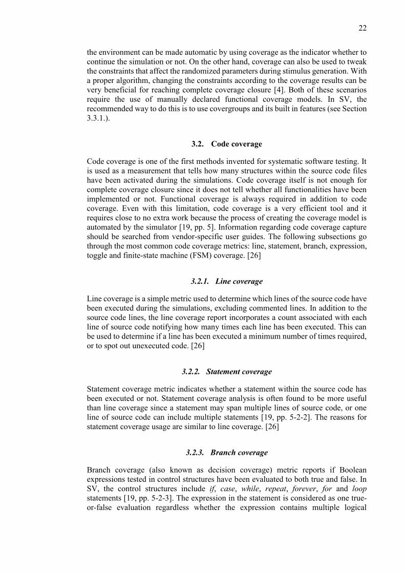
3.2. Code coverage
Code coverage is one of the first methods invented for systematic software testing. It
is used as a measurement that tells how many structures within the source code files
have been activated during the simulations. Code coverage itself is not enough for
complete coverage closure since it does not tell whether all functionalities have been
implemented or not. Functional coverage is always required in addition to code
coverage. Even with this limitation, code coverage is a very efficient tool and it
requires close to no extra work because the process of creating the coverage model is
automated by the simulator [19, pp. 5]. Information regarding code coverage capture
should be searched from vendor-specific user guides. The following subsections go
through the most common code coverage metrics: line, statement, branch, expression,
toggle and finite-state machine (FSM) coverage. [26]
3.2.1. Line coverage
Line coverage is a simple metric used to determine which lines of the source code have
been executed during the simulations, excluding commented lines. In addition to the
source code lines, the line coverage report incorporates a count associated with each
line of source code notifying how many times each line has been executed. This can
be used to determine if a line has been executed a minimum number of times required,
or to spot out unexecuted code. [26]
3.2.2. Statement coverage
Statement coverage metric indicates whether a statement within the source code has
been executed or not. Statement coverage analysis is often found to be more useful
than line coverage since a statement may span multiple lines of source code, or one
line of source code can include multiple statements [19, pp. 5-2-2]. The reasons for
statement coverage usage are similar to line coverage. [26]
3.2.3. Branch coverage
Branch coverage (also known as decision coverage) metric reports if Boolean
expressions tested in control structures have been evaluated to both true and false. In
SV, the control structures include if, case, while, repeat, forever, for and loop
statements [19, pp. 5-2-3]. The expression in the statement is considered as one true-
or-false evaluation regardless whether the expression contains multiple logical

23
operators or not. Very typical application for branch coverage is to check that reset
paths or all states in a case statement have been executed. [26]
3.2.4. Expression coverage
Expression coverage (referred also as condition coverage) is a coverage metric used to
identify if each condition evaluated true and false values. The conditions are Boolean
operands that do not contain logical operations. Thus, expression coverage measures
the Boolean conditions separately from each other. Focused expression coverage
(FEC) is a variation of expression coverage, and it is stronger than condition and
decision coverage. [26]
3.2.5. Toggle coverage
Toggle coverage metric measures the number of times each bit of a register or a wire
has toggled its value. A 100 % toggle coverage is often very hard to reach, and usually
projects settle on a requirement where all ports and registers must have experienced a
zero-to-one and one-to-zero transitions. For example, toggle coverage is often used for
basic connectivity checks between IP blocks. [26]
3.2.6. FSM coverage
Today’s coverage collection tools can also identify FSMs from the source code and
create coverage models for them. For example, it is possible to extract information
regarding how many times each state was visited and each transition occurred. Even
sequential arc coverage to identify state visitation transitions is available. Figure 8
presents an example FSM and its coverage status [19, pp. 5-2-7]. [26]
Transition Visits
S1 → S1S1 → S2S1 → S3S2 → S3S3 → S4S4 → S1
2550
450
4545
State Visits
S1S2S3S4
3000
4545
S4
S1
S2
S3A * BA
A * C D
EF
_
Figure 8. FSM and coverage data with a coverage hole.
3.3. Functional coverage
The goal of functional coverage is to determine if the implemented design
requirements defined in the specification are working as intended. In addition,

24
functional coverage is a good indicator to measure verification progress, better than
code coverage. From a high-level perspective, there are two main steps present when
creating a functional coverage model: identifying the functionality or design to be
verified, and implementing the coverage model using language features to measure the
intended functionality or design [26]. The downside with functional coverage is that it
cannot be extracted automatically; manual work is required. With SV, the
implementation of coverage models can be done with covergroups, or with assertions
while using its cover directive [28]. These SV features are explained more thoroughly
in subsections 3.3.1. and 3.3.2. Figure 9 below demonstrates verification paths to reach
definitive functional coverage [29, p. 9].
Functionalcoverage
DirectedTestcases
Minimal codemodifications
ConstrainedRandom tests
Many runs,different seeds
Identifyholes
Addconstraints
Figure 9. Verification steps to achieve complete functional coverage.
3.3.1. Covergroups
The covergroup construct encapsulates the specification of a coverage model. The
construct is a user-defined type and it can include the following components:
1. A clocking event that is used to synchronize the sampling of the defined
coverage points.
2. A set of coverage points.
3. Cross coverage between defined coverage points.
4. Coverage options to change the behavior of the covergroup or to modify how
multiple covergroup instances are handled.
5. Optional formal arguments used when creating a covergroup instance.
Covergroups can be used to collect information from simple temporal sequences, but
its main advantage comes from collecting and correlating information from multiple
data points [30, pp. 18-2-3]. Once defined, multiple instances of the covergroup can
be created in different contexts. Covergroups can be defined in packages, modules,
programs, interfaces, checkers and classes. Covergroups are instantiated with the
new() operator, similar to classes. When instantiating covergroups inside classes, it
needs to be done inside the class constructor. Figure 10 presents the usage of the
mentioned covergroup components in SV syntax. [8, pp. 19-3]

25
covergroup cg_example @(sampling_event); type.option.merge_instances = 1; // covergroup options // coverpoints LABEL1 : coverpoint readwrite; // automatic bin creation LABEL2 : coverpoint data { bins data_point_1 = { 8'h12 }; bins data_point_2 = { 8'hbe }; } // manual bin creation LABEL3 : cross LABEL1, LABEL2; // cross coverage endgroup
Figure 10. Covergroup syntax in SystemVerilog.
A sampling event (clocking event) defines when a covergroup is sampled [31]. In
Figure 10, the sampling of the covergroup is defined on the first line as
@(sampling_event). If a sampling event is not specified, the user must manually
trigger the covergroup sampling by calling its built-in sample() method [8, pp. 19-3].
This is often the preferred way in UVM environments since hierarchical references are
not allowed inside classes, and the sampling event is easy to synchronize with a
transaction sent by a monitor.
A coverpoint covers a variable or an expression, and it includes a set of bins
associated with its sampled values or its value transitions. The bins can be
automatically generated by the tool or manually declared. Automatic generation is
useful when creating separate bins for a range of values. A bin will be marked as
covered if the value associated to the bin is present in the coverpoint variable at the
covergroup sampling event. Coverpoints can also include a label, and in Figure 10 the
coverpoints and their labels can be found as LABEL1-3. Cross coverage can also be
created between all the bins for the chosen coverpoints (LABEL3). A covergroup can
contain one or more coverpoints. [8, pp. 19-5]
The cumulative covergroup coverage considers the contribution of all instances of
a particular covergroup, and it can be obtained by calling the covergroup’s built-in
get_coveage() method. In contrast, the coverage of a specific covergroup instance can
be acquired by calling the get_inst_coverage() method. The coverage value of a single
covergroup is the weighted average of the coverage of all items (coverpoints and cross
coverages) defined in the covergroup. For coverpoints and cross coverage, the
coverage is simply calculated by dividing the number of covered bins with the total
number of bins. Cross coverage calculation excludes ignored and illegal bins, and
possible duplicates created with the cross coverage. With automatically declared
coverpoints, the maximum number of automatically declared bins is taken into account
in the coverage calculation. [8, pp. 19-11]
3.3.2. Assertions
An assertion specifies excepted behavior in a design and it is mainly used to validate
that the behavior is correct. In addition, the cover directive found in assertions can be
used to provide functional coverage [8, pp. 16-2]. Assertions are not as practical as
covergroups at checking data values, delays and multiple data points, but they are

26
useful at detecting the occurrence of some specific series of Boolean values [30, pp.
18-2-3].
There are two types of assertions: immediate and concurrent assertions. Immediate
assertions are simple, non-temporal domain assertions that are executed like
statements in a procedural block [32, pp. 3]. Immediate assertions can only be specified
with a procedural statement and the evaluation happens immediately with the values
updated at that moment. On the other hand, concurrent assertions describe behavior
that spans over time and are great at verifying specific sequences. The evaluation
model is based on a clock and the assertions is evaluated only at the occurrence of a
clock tick [8, pp. 16-5]. In this work, assertions are only used in the design and the
functional coverage is captured only with covergroups in the test bench.

27
4. UVM MONITORING ENVIRONMENT
This chapter goes through the implementation of the UVM monitoring environment,
which runs in parallel with the existing SV test bench. First, a brief description of the
DUT is given. Then, the chosen coverage points and the implementation of
environment components, like UVM monitors and subscribers, are gone through.
Lastly, the whole test bench is presented.
4.1. Design under test
The DUT chosen for this experiment is a decoder. In normal operation, the decoder is
configured and run, and the results can be checked during and at the end of each run.
The decoders interface includes Advanced Peripheral Bus (APB) and AMBA High-
performance Bus (AHB) buses, and a general interface for interrupt, status and control
signals. Figure 11 shows a top view of the DUT including the interfaces, which are the
main points for collecting the functional coverage.
DECODER
COREFUNCTIONALITY
REGISTERINTERFACE
AHBMASTER MEMORY
APBINTERFACE
GENERALINTERFACE
Figure 11. DUT top view.
The APB bus is used to access the registers of the decoder. The registers include
configuration, control and status registers. The APB bus is the key point with the
functional coverage model since it provides register access and decoder configuration
data values. The decoder has an AHB master that fetches data from memory through
an AHB bus. The memory is modeled with a SV class-based AHB slave.
4.2. UVM verification components
Since no extra DUT driving is required at this point, the first UVM environment
created was quite straightforward. A separate UVM test environment was still required
because if the classes had been instantiated in the SV module environment, the
automatic UVM properties would not have been present. The created UVM hierarchy
includes test, environment, monitor and subscriber classes. The test and environment
28
classes only create the needed subclasses, in this case monitors and subscribers, pass
the virtual interface references and make necessary connections between the
subcomponents. The following subsections take a more detailed look into the
implementation of the UVM monitors and subscribers, which create the actual
functional coverage collection model.
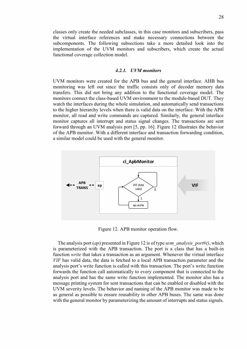
4.2.1. UVM monitors
UVM monitors were created for the APB bus and the general interface. AHB bus
monitoring was left out since the traffic consists only of decoder memory data
transfers. This did not bring any addition to the functional coverage model. The
monitors connect the class-based UVM environment to the module-based DUT. They
watch the interfaces during the whole simulation, and automatically send transactions
to the higher hierarchy levels when there is valid data on the interface. With the APB
monitor, all read and write commands are captured. Similarly, the general interface
monitor captures all interrupt and status signal changes. The transactions are sent
forward through an UVM analysis port [5, pp. 16]. Figure 12 illustrates the behavior
of the APB monitor. With a different interface and transaction forwarding condition,
a similar model could be used with the general monitor.
APBTRANS
ap
cl_ApbMonitor
1
0
ap.write
VIF.data valid
VIF
Figure 12. APB monitor operation flow.
The analysis port (ap) presented in Figure 12 is of type uvm_analysis_port#(), which
is parameterized with the APB transaction. The port is a class that has a built-in
function write that takes a transaction as an argument. Whenever the virtual interface
VIF has valid data, the data is fetched to a local APB transaction parameter and the
analysis port’s write function is called with this transaction. The port’s write function
forwards the function call automatically to every component that is connected to the
analysis port and has the same write function implemented. The monitor also has a
message printing system for sent transactions that can be enabled or disabled with the
UVM severity levels. The behavior and naming of the APB monitor was made to be
as general as possible to ensure reusability in other APB buses. The same was done
with the general monitor by parameterizing the amount of interrupts and status signals.

29
4.2.2. UVM subscribers
The UVM subscribers implement the covergroup models for the decoder and use the
transactions sent by the monitors to sample the covergroups. Two subscribers were
created in total: one for APB and one for the general interface related covergroups.
The APB subscriber collects data regarding register access (read and write) and
decoder configuration values set through the APB bus, and the general interface
subscriber keeps track that all interrupt, status and control signals have been set and
cleared. Both of these subscribers include covergroups and their constructors, and the
write function with additional logic to determine what covergroups to sample with
each transaction. Figure 13 demonstrates how the transactions sent by the monitor are
handled inside the APB subscriber.
cl_Decoder_ApbSubscriber
aeAPB
TRANS
write (apb_rw tx)
apb_rw t; t.addr = tx.addr; t.data = tx.data; t.rw = tx.rw case (t.addr) begin 12'h518 : cg1.sample(); end
cg_* sample()
Figure 13. APB subscriber transaction processing.
The subscribers extend UVM subscribers and thus have a built-in analysis export
(ae) used for receiving transactions. As mentioned in the previous section, the write
function is executed automatically whenever the export receives a transaction. The
write function captures the transaction information to a local transaction parameter to
ensure the data used remains the same, and samples the correct covergroups. The
covergroups were implemented using the covergroup properties presented in Chapter
3.1.1.
4.3. Parallel test bench
The finished test bench uses the IP’s existing test bench to execute the original test
program flow: stimulate the DUT and check design correctness. The original test
bench is done in a SV module based manner. In addition, the test bench has the UVM
monitoring environment described in the previous sections running in parallel to the
module environment. The whole test bench structure is presented in Figure 14,
highlighting the separation of the UVM and module hierarchies.

30
cl_Decoder_Test
cl_Decoder_Env
Top
C-MODELTest
Program
cl_ApbSubscriber
cl_GeneralSubscriber
DUT
cl_ApbMonitor
cl_GeneralMonitor
UVM hierarchy SV module hierarchy
Figure 14. Full test bench for the monitoring environment.
The top SV module instantiates the DUT module, and the decoder test program as
automatic SV program. The test program uses the built-in direct programming
interface (DPI) [33] to integrate a C-model for the decoder, which is used to calculate
the configuration parameters and expected results, and to do correction checks between
the C-model and DUT results. In one run, the test program starts the C-model with a
set of parameters and the C-model calculates required decoder parameters and starts
the DUT with the chosen settings. Finally, the DUT and reference results are
compared. The DUT is configured and started via the APB interface.
In addition, the top module also starts the construction of the UVM environment and
sets the references of the DUT interfaces to the UVM configuration database. The top
selects which UVM test class is the top class in the UVM hierarchy, and that test will
construct the rest according to its build and connect phase functions. Here, the
cl_Decoder_Test test class creates the cl_Decoder_Env environment class and the
environment creates the monitors and subscribers, connects them and sets the correct
interface references to the monitors.
The simulations are done with Mentor’s Questa simulator. Coverage is captured by
storing the code and functional coverage into a UCDB file in the end of simulations.
The coverage data is transformed into HTML format using Questa’s coverage features
for better readability. The simulator also keeps log of messages that appear during
compile, optimization and simulation phases, and the logs are stored to separate files.
Questa’s simstats formal argument is used to get accurate data regarding different
simulation execution times. This information is used in performance comparison of
the different test benches. The results are gone through in Chapter 6.

31
5. COMPLETE UVM ENVIRONMENT
This chapter presents the second part of the experiment, where the whole test bench is
converted into the UVM environment. The chapter starts with the modifications made
to the UVM environment shown in previous chapter to make it able to drive the
interfaces and model the AHB memory. In addition, the test program conversion to
UVM test format is gone through and the final test bench is presented.
5.1. Addition of UVM agents
With the final test bench, the UVM environment needed to be able to do the same DUT
driving as the original module based test program. Thus UVM agents were created for
the APB, AHB and general interface. The APB and general interface agents include a
driver and a sequencer as new components, and the existing monitor presented in the
previous chapter. The AHB agent has only a slave component since its only function
is to act as memory that is connected to a AHB bus. The general structure of a driving
and monitoring UVM agent is illustrated in Figure 15.
Agent
Sequencer VIFDriver
Monitor
Figure 15. UVM agent and its subcomponents.
5.1.1. Drivers and sequencers
The drivers extend the UVM driver class and their main function is to wait for new
transactions to be ready in the sequence item port found inside the drivers, and to
transform the transactions into DUT pin wiggles by using the virtual interface
reference to the DUT interface. The drivers were built to capitalize the UVM phasing,
making them start and operate automatically. They also support passive-active

32
configuration, where passive agent only instantiates a monitor and active adds the
driving components as well. The APB driver checks whether the incoming transaction
is a read or write operation and executes them according to the APB protocol, and the
general interface driver simply sets the selected control signals active and releases
them after few clock cycles.
The sequencers were implemented to make the transaction passing to different
drivers more straightforward. The sequencers in this test bench did not need any extra
features, thus the base UVM sequencers were used with minor naming changes to fit
the IP’s test bench. In this test bench, the top UVM test class adds sequences to the
sequencers, and the sequencers parse the sequences into transactions for the drivers to
fetch.
5.1.2. AHB slave
The implemented AHB slave follows the same functionality as the original slave to
ensure timing regarding AHB memory accesses remains the same. Thus the slave’s
functionality was ported unchanged to be UVM environment compatible, and only
minor additions were made to the slave automation using the UVM phases. The slave
uses a SV queue as the memory container, and an automatically running function that
either stores data to the container (write) or puts data from the container to the AHB
bus (read). Because the DUT uses two memories with different AHB bus data widths,
the AHB slave class and its functions were parameterized.
5.2. Test program
In the new UVM environment, the test program was implemented inside the top UVM
test class cl_Decoder_Test. Linking the C-model to the UVM test class was
problematic since the C code required access to SV tasks through the DPI, and class
tasks cannot be exported unless they are declared as static. On the other hand, static
tasks would have nullified the hierarchical benefits got from the UVM environment.
This problem was bypassed by importing the C-model inside an SV interface wrapper
and giving the UVM test class a reference to this interface. This structure is presented
in Figure 16 below.
VIF
cl_Decoder_Test in_CModel
C-MODEL
- Tasks to call C-Model and vice versa- Update VIF- Inform cl_Decoder_Test class
Functionality:
cl_Decoder_Env
virtual in_CModel vif;vif.ta_callCModel;
Figure 16. UVM Test class and C-model communication.

33
The structure presented in Figure 16 allows the test class to call any tasks found
inside the in_CModel interface through the virtual interface reference. All data
between the test class and C-model is transferred through the reference. This requires
some additional synchronization compared to a straight task call, but nevertheless was
found to be the best solution without modifying the C source code.
Apart from the C-model integration, there were no compatibility issues with the test
program implementation inside the UVM test class. The program was divided into
subtasks inside the class, and parameters regarding configuration and simulation
conditions were declared with the rand type with additional constraints. Tasks to fetch
and check the covergroup coverage values from the subscribers were also
implemented. The main program loop was changed to be coverage-driven, where the
covergroup coverage values are used as a condition whether to continue or not. The
top includes a set of coverage goal parameters that can be tweaked to modify the
importance of some coverage segments in the evaluation of the end condition. In
addition, reporting tasks were implemented to inform the user about test progress, and
configuration and coverage values.
5.3. Final test bench
The final UVM test bench consists of the new components presented in this chapter
and the previous test bench shown in Chapter 4.3. All DUT driving is now done by
different UVM agents and the data is processed inside the top UVM test class
cl_Decoder_Test, disregarding the data calculated by the C-model running inside the
in_CModel interface. The complete test bench is presented in Figure 17.
cl_Decoder_Test
cl_Decoder_Env
Top
C-MODELin_CModel
cl_AhbAgent
cl_ApbAgent
cl_GeneralAgent
DUT
cl_ApbSubscriber
cl_GeneralSubscriber
Config
Figure 17. Final UVM test bench.

34
Here, the cl_Decoder_Env environment instantiates the agents instead of only
monitors. The environment also includes additional configuration parameters used
when creating the agents. The Top module only instantiates the DUT and necessary
interfaces for the UVM test bench, leaving out the test program found in the parallel
test bench. Other than these changes, the test bench structure and instantiation remains
the same as in the previous test bench shown in Chapter 4.3. No changes were made
to the coverage data collection or simulation logs.

35
6. RESULTS
This chapter presents the coverage and simulation performance results got from the
original, original with monitoring and full UVM test benches shown in Sections 4.3.
and 5.3. First, Section 6.1 shows code and functional coverage statistics got from
Questa’s coverage reports. Then, Section 6.2 presents data regarding test bench
performance for all test benches used in this experiments.
6.1. Coverage
Both code and functional coverage results were extracted from the HTML reports
generated by Questa. Practically, 100 % coverage should be reached in all coverage
fields, and if not, exclusions with explanations should be used. The results presented
in this chapter use no exclusions. And since the UVM environment uses the original
test program flow, some functional coverage misses present in the original test bench
will be present in the UVM the bench as well. The changes mainly come from
changing the decoder configuration parameters to randomized parameters. Code and
functional coverage results are shown in the following subsections.
6.1.1. Code
The code coverage statistics for the original and UVM test bench are presented in
Figures 18 and 19, and the coverage number differences of these two are highlighted
in Figure 20 (UVM compared to original). The code coverage was limited to the
decoder unit, leaving out all test bench items. With the UVM test bench, 85 % coverage
goal was used for the cg_Decoder_Config_Iterations covergroup (see Section 6.1.2.),
and 100 % for other configuration and interrupt covergroups. These simulation goals
resulted in a total of 7112 decoder test runs. The original test bench was run for the
whole test program duration, which resulted in a total of 9144 test runs.
TOTAL
la_Include
u_Decoder_Control
u_Decoder_ApbAdapter
Scope TOTAL Statement Branch
65.12
87.50
85.61
78.14
88.99
100.00
100.00
100.00
66.98
--
--
--
FEC Expr. FEC Cond. Toggle
u_Decoder_PeripAccess
u_Decoder_Tcm
u_Decoder_Ram
u_Decoder_MemoryIntf
u_Decoder_Core
u_PowerControl 31.64
51.90
85.21
71.38
92.96
91.02
84.46
51.88
95.76
82.53
100.00
99.47
37.02
60.06
92.13
77.41
100.00
97.64
64.64
75.00
20.00
78.57
66.66
53.84
100.00
100.00
--
75.00
31.75
--
0.00
--
--
33.78
82.14
50.00
--
90.00
73.24
--
16.74
78.26
67.76
59.96
56.02
46.94
78.89
93.00
Figure 18. Code coverage statistics (percentage) of the decoder unit got from the
original test bench.

36
TOTAL
la_Include
u_Decoder_Control
u_Decoder_ApbAdapter
Scope TOTAL Statement Branch
65.65
100.00
87.99
78.48
89.03
100.00
100.00
100.00
67.07
--
--
--
FEC Expr. FEC Cond. Toggle
u_Decoder_PeripAccess
u_Decoder_Tcm
u_Decoder_Ram
u_Decoder_MemoryIntf
u_Decoder_Core
u_PowerControl 31.67
52.31
85.21
71.38
92.96
91.11
84.46
52.09
95.76
82.53
100.00
99.47
37.02
60.36
92.13
77.41
100.00
97.64
66.66
100.00
20.00
85.71
66.66
53.84
100.00
100.00
--
75.00
31.75
--
0.00
--
--
33.78
82.14
50.00
--
90.00
73.74
--
16.89
78.26
68.78
61.47
56.02
46.94
78.89
93.48
Figure 19. Code coverage statistics (percentage) of the decoder got from the UVM
test bench.
TOTAL
la_Include
u_Decoder_Control
u_Decoder_ApbAdapter
Scope TOTAL Statement Branch
+ 0.53
+ 12.50
+ 2.38
+ 0.34
+ 0.04
--
--
--
+ 0.09
--
--
--
FEC Expr. FEC Cond. Toggle
u_Decoder_PeripAccess
u_Decoder_Tcm
u_Decoder_Ram
u_Decoder_MemoryIntf
u_Decoder_Core
u_PowerControl + 0.03
+ 0.41
--
--
--
+ 0.09
--
+ 0.21
--
--
--
--
--
+ 0.30
--
--
--
--
+ 2.02
+ 25.00
--
+ 7.14
--
--
--
--
--
--
--
--
--
--
--
--
--
--
--
--
+ 0.50
--
+ 0.15
--
+ 1.02
+ 1.51
--
--
--
+ 0.48
Figure 20. Differences of the UVM test bench code coverage compared to the
original one (in percent).
It was known that the original test bench did stress the DUT quite thoroughly in the
functional aspect. The behavior of the test program and the DUT operation also caused
the code coverage to reach reasonably high values rather quickly, only getting small
improvements with a very high number of tests. However, even with this baseline the
randomization present in the UVM environment brought some increase to the code
coverage with a lesser amount of tests, as it can be seen from Figure 20. The main
reason for this is the different toggle values got from randomization, which also caused
few extra statements, branches and expression to be executed.
6.1.2. Functional
Figures 21 and 22 show the functional coverage got from the covergroups for the
original and UVM test bench, in respective order. The simulation coverage goals for
the UVM environment, and the total number of decoder test runs for the UVM and the
original test bench were the same as shown in Section 6.1.1. If 100 % coverage goal
was also used for the iterations covergroup, the total number of test runs was 10033.

37
Covergroup Total Bins Hits Hits % Goal % Coverage %
68.07%100.00%46.92%84179cg_Decoder_Registers
100.00%100.00%46.01%127127cg_Decoder_Config_Length
16.12%100.00%16.12%531cg_Decoder_Config_Iterations
100.00%100.00%100.00%44cg_Decoder_Config_Prediction
100.00%100.00%100.00%22cg_Decoder_Config_CRC
100.00%100.00%100.00%22cg_Decoder_Config_ABS
100.00%100.00%100.00%1212cg_Decoder_Interrupts
100.00%100.00%100.00%1212cg_Decoder_Status
0.00%100.00%0.00%08cg_Decoder_Control
84
Figure 21. Covergroup functional coverage of the original test bench.
Covergroup Total Bins Hits Hits % Goal % Coverage %
68.07%100.00%46.92%84179cg_Decoder_Registers
100.00%100.00%46.01%127127cg_Decoder_Config_Length
87.09%100.00%87.09%2731cg_Decoder_Config_Iterations
100.00%100.00%100.00%44cg_Decoder_Config_Prediction
100.00%100.00%100.00%22cg_Decoder_Config_CRC
100.00%100.00%100.00%22cg_Decoder_Config_ABS
100.00%100.00%100.00%1212cg_Decoder_Interrupts
100.00%100.00%100.00%1212cg_Decoder_Status
25.00%100.00%25.00%28cg_Decoder_Control
84
Figure 22. Covergroup functional coverage of the UVM test bench with iterations
coverage goal of 85 %.
As it can be seen from Figures 21 and 22, the main neglects of the original test bench
are the iterations configuration, and control covergroups. The parameter that
determines the maximum iterations of the decoder was added to the pool of
randomized parameters in the UVM test bench, making the coverage results much
better for the cg_Decoder_Config_Iterations covergroup. The usage of control inputs
was missing, and a small feature was added to make the usage possible, resulting in
the 25 % coverage increase in the cg_Decoder_Control covergroup. The UVM envi-
ronment goes through a wider range of configuration values than the original test
bench with lesser tests. However, if all combinations of the configuration values would
be gone through, the total number of test runs would be much higher than the 9144 test
runs with the original test bench due to duplicate random values.
As it was stated in the previous section, the functional aspect of the DUT was already
thoroughly tested with the original test bench. The results show that randomization
itself did not bring much addition to the overall functional coverage. The main reason

38
for this was that the DUT operates in one specific way, not allowing much free space
other than the decoder configuration. The iterations configuration in the original test
bench was low due to using the most fitting value with majority of the runs, and
stressing only both maximum and minimum values. Nevertheless, if a range of
possible values have been implemented, all of them should be tested. The iterations
covergroup being higher with the UVM test bench is reasoned with the original test
bench being partly lacking, rather than with the benefits of the randomization. The
same can be said about the cg_Decoder_Control covergroup.
6.2. Test bench performance
Test bench performance is measured in the terms of total CPU run time for each
simulation using the different test benches presented so far. The total CPU run time
consists of CPU time spent on optimization (Vopt), elaboration, simulation and Tcl
command phases. The run time logging was enabled by using Questa’s simstats formal
argument. The CPU times were taken straight from Questa’s log, and no extra profiling
properties were used.
Simulation run times were measured with a shorter, single decoder test runs with
multiple recursions, and a full decoder test runs with fewer recursions due to long
simulation times. The UVM environment was run in manual mode to make sure the
test flow was identical to the original test program. The total CPU run time results for
these both cases can be found in Figures 23 and 24 below.
Figure 23. Total simulation CPU run time comparison using one decoder test run.
31
8,5
5 33
1,0
2
24
1,0
2
31
9,5
4 33
1,2
6
24
2,7
2
31
9,9
6 33
1,5
2
24
4,8
5
200
220
240
260
280
300
320
340
Original Original + monitoring UVM
Sim
ula
tio
n t
ime
(s)
Test bench used
Min
Average
Max

39
Figure 24. Total simulation CPU run time comparison using the full set of test runs.
Figures 23 and 24 show an expected result that the original test bench with
monitoring enabled has longer run time compared to the original test bench only. With
monitoring enabled, the increase in total CPU run time is around 4 % in both cases,
which is not a groundbreaking time delay considering there are two test programs
running in parallel.
The run times got from the UVM environment runs are surprising, since the UVM
test program has extra synchronization compared to the original test bench because of
the inconvenience of the C-model implementation. Due to this, the expectations were
even worse than with the original test bench with monitoring enabled. Nevertheless,
with this test program flow the UVM test bench provided significantly faster total CPU
run times than the other two test benches. In the single test run, the UVM test bench
total run time was around 24 % faster compared to the original test bench, and with
the full test run, around 26 % faster. With longer simulations, improvements like this
have a notable impact.
26
3,4
6 27
3,3
3
19
4,2
7
26
5,3
0 27
7,1
3
19
5,5
8
26
8,6
7 27
9,3
2
19
7,5
1
160
180
200
220
240
260
280
300
Original Original + monitoring UVM
Sim
ula
tio
n t
ime
(min
)
Test bench used
Min
Average
Max

40
7. DISCUSSION
The objective of this thesis was to develop a UVM simulation environment based on
an existing SV test bench. The environment was created to test the applicability of a
UVM environment in IP verification compared to a more traditional module-based SV
environment. The results got from this thesis show both positive and negative aspects
of the adequacy of the UVM test bench with this particular IP.
The compatibility of a module-based SV test program and a class-based UVM test
is good. The implementation done in this thesis showed only difficulties with the C-
model integration. This problem seems to occur only when the C-model also uses tasks
or functions from the SV side. The problem can be bypassed with some gimmicks, but
it can be impractical for people working with test benches that often incorporate
bidirectional C-models. This proposes that an update to the SV DPI and UVM interface
could be done, making the C-model integration less problematic. In addition, it is
important to remember that hierarchical references to the DUT do not go well together
with class-based environments. With the test bench used in this thesis, this did not
prove to be a problem, but with module-based environments incorporating a lot of
hierarchical references, or with users accustomed to use hierarchical references in their
verification, this limitation can feel frustrating. Class-based environments simply need
a different kind of approach. Regardless, the use of hierarchical references is
considered as a bad verification practice since it greatly reduces reusability of the
verification components, and they should only be used when necessary.
Code coverage can be improved with constrained random stimulus. This is mostly
due to large increase in signal bit toggles, and the amount of total test run. Only the
high quantity of tests itself is enough to test most conditions, statements and branches
found in the source code, giving high code coverage. On the other hand, a good
functional coverage is mainly determined whether the test program executes specific
functional patterns or not. The most crucial part is to understand the DUT operation
and write test patterns that stress the different operation schemes. Randomization itself
does not automatically give a good functional coverage, but it can always bring out
new bugs in the tested operation scheme since a larger amount of different values are
used in the stimulus. For both code and functional coverage, the way how the DUT
operates matters a lot. Even with larger designs, if the operation is limited to one
specific way, the improvement received from random stimulus is not that great. The
DUT used in this thesis partially represents this kind of scheme. On the other hand, if
the DUT has data inputs with a wide range of legal values, randomization usually
brings major benefits. Yehia A. studied constrained random stimulus for achieving
faster coverage closure [34]. In his work, Yehia used a direct memory access (DMA)
IP and an Ethernet media access control (MAC) IP, both allowing a high degree of
direct input stimuli, to compare constrained random stimulus to directed testing. The
results Yehia measured showed that constrained random stimulus provided much
faster coverage closure and coverage values with lesser amount of transactions used to
stimulate the DUTs.
The different test bench performance results presented in Chapter 6 indicate that
UVM environments can provide significantly faster total test bench run times
compared to module-based SV environments. With the DUT and test program used in
this thesis, the UVM test bench’s total run time was between 24 % and 26 % faster
than the original module-based SV test bench’s. With test cases lasting multiple hours,
the time saved was measured in hours. Because no simulator profiling properties were

41
used, it is hard to pin point the specific reasons for the improvement in the test bench
total run time. Since the C-model integration required concurrent processes to
implement the additional synchronization and communication between the UVM
environment and the C-model, it is possible that the simulation server distributed its
work load more efficiently, giving the DUT simulation more computation capacity.
To find out whether this or something else causes the speedup, profiling needs to be
used to acquire instance specific data, but that falls outside of the scope of this thesis.
Söderlund T. also studied the performance of an UVM environment compared to a
legacy test bench in his thesis [20]. Söderlund’s UVM test bench was around 50 %
slower compared to the original test bench, but also had added functionality, making
the scenario slightly different than in this thesis.
There are also some downsides when adopting UVM verification. The UVM can be
a bit overwhelming in terms of environment complexity. Typically, more time spent
with UVM environments is required to be familiar with the common structure and
operation of a UVM environment than with traditional, module-based environments.
In addition, creating a single UVM environment from scratch is not much more
efficient than creating an environment of a different type; sometimes it can be even
more time consuming. The real benefit with UVM is acquired when a base set of UVM
components exist and the verification engineers have the basic skillset to work with
UVM. At this point most of the unnecessary hassle when working with UVM
environments has been eliminated, and creating new verification environments for the
project’s needs requires much less working hours.
The goal of this thesis was to study the validity of UVM in IP verification. The goal
was achieved by successfully creating an efficient UVM environment based on an
existing SV test bench. The most interesting results got from this experiment were the
UVM environment performance gains. Proving that porting versatile test benches to
UVM is possible while gaining more code coverage by enabling randomization also
serves its purpose. It would be really beneficial to replicate this kind of study, where
no additional functionality is added to the UVM test bench, with different IPs. This
would provide data regarding whether the performance or coverage improvements
would be present with other types of test benches, or not. Nevertheless, based on the
results presented in this thesis, UVM is an excellent option for versatile IP verification
for any size of a design.
This thesis can serve as a starting point for future experiments regarding class-based
IP verification involving existing test benches. When creating a coverage-driven UVM
environment, the basic steps should be similar to what was presented in this thesis. In
addition, the created UVM agents for different buses can be reused if more UVM
environments are desired in the future.

42
8. SUMMARY
This thesis studies the advantages and disadvantages of UVM in IP verification. This
is done by creating a CDV environment using UVM from an already existing module-
based SV test bench. The history, concept and main features of UVM is presented, and
a look into code and functional coverage is taken. The final conclusions are made
based on the coverage and simulation performance results got from the different test
benches.
UVM is a widely supported SV class library used for digital design verification.
UVM follows the principles of object-oriented programming and utilizes proven OOP
features like classes and inheritance. In addition to the OOP principles, UVM has
multiple useful built-in properties, like phasing, transactions, message reporting and
configuration database, to help with the test bench creation. Typical environments built
with UVM have a clear class hierarchy, are able to drive and monitor the DUT, and do
functional checking and coverage collection.
Coverage can be divided into two concepts: code and functional coverage. Code
coverage is an automatically generated metric used to measure whether specific
sections of the source code have been executed or not. Functional coverage is a
manually declared model that represents the key functional features of the DUT, and
shows whether those features have been tested or not. In SV, functional coverage
models can be written with covergroups or assertions. Covergroups can also be used
to enable CDV. Both code and functional coverage go hand-in-hand, and both are
required to achieve complete coverage closure.
In the practical part, UVM monitor and subscriber components were first created to
capture functional coverage from the IP’s original test bench. For the full UVM test
bench, UVM agents were created to enabled driving of the DUT, and the monitors
were transferred inside the agents. The original test program was ported to the UVM
side, leaving out the original test program. The coverage results were collected in the
same manner as with the monitoring test bench.
The results got from the three different test bench setups show that the full UVM
environment provided performance improvements of 24 - 26 % to total simulation run
time. Also, the constrained random stimulus found in the UVM test bench gave slight
improvements to code coverage, but the random stimulus itself did not have a big
impact on functional coverage. With functional coverage, randomization can aid the
process of creating stimulus with multiple different values, but the final coverage
results are determined mainly by the test patterns gone through and the coverage model
itself. In this experiment, the DUT’s operation flow was quite restricted, which also
contributed to the low impact of the randomization. Nonetheless, UVM is an excellent
option for IP verification based on the experiment done in this thesis.
43
9. REFERENCES
[1] Chen, KC. (2003) Assertion-Based Verification For SoC Designs. In: IEEE
5h International Conference on ASIC, Vol. 1, pp. 12-15, San Jose,
California, USA.
[2] Vitullo F., Saponara S., Petri E., Casula M., Fanucci L., Maruccia G.,
Locatelli R. & Coppola M. (2009) A reusable coverage-driven verification
environment for Network-on-Chip communication in embedded system
platforms. In: IEEE Seventh Workshop on Intelligent solutions in Embedded
Systems, June 25-26, pp. 71-77.
[3] Stotland I., Shpagilev D. & Starikovskaya N. (2016) UVM Based
Approaches to Functional Verification of Communication Controllers of
Microprocessor Systems. In: IEEE 2016 East-West Design & Test
Symposium (EWDTS), October 14-17, pp. 1-4.
[4] Šimková M. & Kotásek Z. (2015) Automation and Optimization of
Coverage-driven Verification. In: IEEE 2015 Euromicro Conference on
Digital System Design (DSD), August 26-28, pp. 87-94.
[5] Accelera. (Accessed 30.1.2017) Universal Verification Methodology
(UVM) 1.2 Class Reference. URL:
http://www.eda.org/downloads/standards/uvm.
[6] Accelera. (Accessed 30.1.2017) Universal Verification Methodology
(UVM) 1.2 User’s Guide. URL:
http://www.eda.org/downloads/standards/uvm.
[7] Meade K. & Rosenberg S. (2013) A Practical Guide to Adopting the
Universal Verification Methodology (UVM) Second Edition. Cadence
Design Systems, Inc., San Jose, California, USA, 296 p.
[8] IEEE. (2013) IEEE Standard for SystemVerilog--Unified Hardware Design,
Specification and Verification Language. IEEE Std 1800-2012, New York,
USA, 1315 p.
[9] Doulos. (Accessed 31.1.2017) Doulos Infocenter for Universal Verification
Methodology. URL: https://www.doulos.com/knowhow/sysverilog/uvm/.
[10] Yadav H. N. (2008) Object-oriented C++ programming. Laxmi Publications
Pvt. Ltd., New Delhi, India, 452 p.
[11] Schuster S. & Schulze S. (2012) Object-Oriented Design in Feature-
Oriented Programming. In: ACM Proceedings of the 4th International
Workshop on Feature-Oriented Software Development (FOSD), September
24-25, Dresden, Germany, pp. 25-28.
[12] Barclay K. A. & Savage J. (2003) Object-Oriented Design with UML and
Java. Butterworth-Heinemann, Oxford, United Kingdom, 428 p.

44
[13] Parsons D. (1997) Object-Oriented Programming With C++ 2nd edition.
Continuum International Publishing Group, New York, USA, 395 p.
[14] Booch G. (1994) Object-Oriented Analysis and Design with Applications
2nd Edition. Addison Wesley Longman, Inc., 608 p.
[15] Raghuvasnhi S. & Singh V. (2014) Review On Universal Verification
Methodology (UVM) Concepts for Functional Verification. In: International
Journal of Electrical, Electronics and Data Communication, Vol. 2, pp. 101-
107.
[16] Bromley J. (2013) If SystemVerilog Is So Good, Why Do We Need the
UVM? Sharing responsibilities between libraries and the core language. In:
IEEE 2013 Forum on Specification & Design Languages (FDL), September
24-26, pp. 1-7.
[17] Francesconi J., Rodriguez J. & Julián P. M. (2014) UVM Based Testbench
Architecture for Unit Verification. In: IEEE 2014 Argentine Conference on
Micro-Nanoelectronics, Technology and Applications (EAMTA), July 24-
25, pp. 89-94.
[18] Zhaohui H., Pierres A., Shiqing H., Fang C., Royannes P., See E. P. & Hoon
Y. L. (2012) Practical and Efficient SOC Verification Flow by Reusing IP
Testcase and Testbench. In: IEEE 2012 International SoC Design
Conference (ISOCC), November 4-7, pp. 175-178.
[19] Piziali A. (2008) Functional Verification Coverage Measurement and
Analysis. Springer Science+Business Media LLC, New York, USA, 193 p.
[20] Söderlund T. (2016) Reusable UVM Testbench Template. Master’s thesis.
University of Oulu, Electrical Engineering, Oulu.
[21] Kärenlampi L. (2016) Simulation performance profiling and optimization in
UVM based verification environment. Master’s thesis. University of Oulu,
Electrical Engineering, Oulu.
[22] Montesano J. & Litterick M. (2014) Verification Mind Games: how to think
like a verifier. In: DVCon 2014, March 4, pp. 1-7.
[23] Wile B., Goss J. C. & Roesner W. (2005) Comprehensive Functional
Verification: The Complete Industry Cycle. Morgan Kaufmann Publishers,
San Francisco, USA, 704 p.
[24] Sprott J., Marriott P. & Graham M. (2015) Navigating The Functional
Coverage Black Hole: Be More Efficient At Functional Coverage
Modelling. In: DVCon 2015, March 4, pp. 1-12.
[25] Minto B. (2010) The Pyramid Principle: Logical Writing, Thinking and
Problem Solving Third Edition. Prentice Hall, 177 p.

45
[26] Allan G., Chidolue G., Ellis T., Foster H., Horn M., James P. & Peryer M.
(Accessed 10.2.2017) Coverage Cookbook. Mentor Graphics, URL:
https://verificationacademy.com/.
[27] Guo Y., Qu W., Li T. & Li S. (2007) Coverage Driven Test Generation
Framework for RTL Functional Verification. In: IEEE 10th IEEE
International Conference on Computer-Aided Design and Computer
Graphics, October 15-18, pp. 321-326.
[28] Flake P. (2013) Why SystemVerilog? In: IEEE 2013 Forum on Specification
& Design Languages (FDL), September 24-26, pp. 1-6.
[29] Spear C. (2008) SystemVerilog for Verification: A Guide to Learning the
Testbench Language Features Second Edition. Springer Science+Business
Media LLC, 465 p.
[30] Cerny E., Dudani S., Havlicek J. & Korchemny D. (2014) SVA: The Power
of Assertions in SystemVerilog Second Edition. Springer International
Publishing, 590 p.
[31] Cheng A.-C., Yen C.-C. & Jou J.-Y. (2012) A Formal Method to Improve
SystemVerilog Functional Coverage. In: IEEE 2012 IEEE International
High Level Design Validation and Test Workshop (HLDVT), November 9-
10, pp. 56-63.
[32] Mehta A. B. (2014) SystemVerilog Assertions and Functional Coverage:
Guide to Language, Methodology and Applications Second Edition. Sprinter
International Publishing, 406 p.
[33] Aynsley J. (Accessed 28.2.2017) SystemVerilog Meets C++: Re-use of
Existing C/C++ Models Just Got Easier. Doulos, URL:
http://www.doulos.com/knowhow/sysverilog/DVCon10_dpi_paper/System
Verilog%20meets%20C++.pdf.
[34] Yehia A. (2013) Faster Coverage Closure: Runtime Guidance of
Constrained Random Stimuli by Collected Coverage. In: IEEE 2013 Saudi
International Electronics, Communications and Photonics Conference
(SIECPC), April 27-30, pp. 1-6.