Master’s Thesis Nr. 161Master’s Thesis Nr. 161 Systems Group, Department of Computer Science,...
79
Master’s Thesis Nr. 161 Systems Group, Department of Computer Science, ETH Zurich Explicit OS support for hardware threads by Andrei Poenaru Supervised by Prof. Timothy Roscoe Reto Achermann Gerd Zellweger September 2016 - March 2017
Transcript of Master’s Thesis Nr. 161Master’s Thesis Nr. 161 Systems Group, Department of Computer Science,...

Master’s Thesis Nr. 161
Systems Group, Department of Computer Science, ETH Zurich
Explicit OS support for hardware threads
by
Andrei Poenaru
Supervised by
Prof. Timothy RoscoeReto AchermannGerd Zellweger
September 2016 - March 2017


Abstract
Current mainstream processors provide multiple SMT (i.e., simultaneousmultithreading) lanes on top of each physical core. These hardware threadsshare more resources (e.g., execution units and caches) when compared to CPUcores, but are managed by operating systems in the same way as if they wereseparate physical cores. This Thesis explores the interaction between hardwarethreads and proposes an extension to the Barrelfish OS, meant to improve theperformance of a system by adequately handling SMT lanes. On an Intel HaswellCPU, with 2-way SMT via Hyper-Threading Technology, each SMT lane had2/3 of the processing power that was yielded by the physical core with a singleactive hardware thread. The multi-HT CPU Driver (i.e., Barrelfish’s microker-nel) is able to modify the set of active hardware threads with an overhead in theorder of thousands of processor cycles, which means that it can quickly adaptto the parallelism exhibited by the workload.
Contents
1 Introduction 41.1 Motivation . . . . . . . . . . . . . . . . . . . . . . . . . . . . . . 41.2 Thesis Structure . . . . . . . . . . . . . . . . . . . . . . . . . . . 5
2 Background 62.1 Simultaneous Multithreading . . . . . . . . . . . . . . . . . . . . 62.2 Intel R© Hyper-Threading Technology . . . . . . . . . . . . . . . . 62.3 The Barrelfish OS . . . . . . . . . . . . . . . . . . . . . . . . . . 82.4 Synchronizing Hardware Threads . . . . . . . . . . . . . . . . . . 10
3 Related Work 123.1 Elfen Scheduling . . . . . . . . . . . . . . . . . . . . . . . . . . . 123.2 Asynchronous System Calls . . . . . . . . . . . . . . . . . . . . . 133.3 Exclusive Access to a Microkernel . . . . . . . . . . . . . . . . . . 14
4 Interaction between Hardware Threads 174.1 Synchronization . . . . . . . . . . . . . . . . . . . . . . . . . . . . 18
4.1.1 Normal Measurement Setup . . . . . . . . . . . . . . . . . 184.1.2 Reduced Measurement Setup . . . . . . . . . . . . . . . . 264.1.3 Cost of HT Synchronization . . . . . . . . . . . . . . . . . 30
4.2 The Fhourstones Benchmark . . . . . . . . . . . . . . . . . . . . 334.3 Context Switching . . . . . . . . . . . . . . . . . . . . . . . . . . 374.4 Hardware Details . . . . . . . . . . . . . . . . . . . . . . . . . . . 394.5 Conclusions on Hardware Threads Interaction . . . . . . . . . . . 40
5 Multi-HT CPU Driver 425.1 Sharing a Kernel . . . . . . . . . . . . . . . . . . . . . . . . . . . 425.2 The Kernel Stacks . . . . . . . . . . . . . . . . . . . . . . . . . . 445.3 The BIG-Kernel Lock . . . . . . . . . . . . . . . . . . . . . . . . 455.4 The CPU Driver’s Boot Entry Point . . . . . . . . . . . . . . . . 455.5 The CPU Driver’s Syscall Entry Point . . . . . . . . . . . . . . . 475.6 The CPU Driver’s Interrupts and Exceptions Entry Point . . . . 485.7 Booting an Application Hardware Thread . . . . . . . . . . . . . 505.8 The Hardware Thread Control Block . . . . . . . . . . . . . . . . 52
1

CONTENTS 2
5.9 Using a Multi-HT CPU Driver . . . . . . . . . . . . . . . . . . . 54
6 User Domains on Top of a Multi-HT CPU Driver 556.1 Scheduler . . . . . . . . . . . . . . . . . . . . . . . . . . . . . . . 556.2 Domains, Dispatchers and Hardware Threads . . . . . . . . . . . 566.3 Core Local RPC and Message Passing . . . . . . . . . . . . . . . 576.4 HT Management . . . . . . . . . . . . . . . . . . . . . . . . . . . 606.5 FPU Registers . . . . . . . . . . . . . . . . . . . . . . . . . . . . 646.6 Benchmark . . . . . . . . . . . . . . . . . . . . . . . . . . . . . . 646.7 Optimizing the Scheduler . . . . . . . . . . . . . . . . . . . . . . 70
7 Conclusions and Future Work 72

Acknowledgements
I would like to thank Prof. Timothy Roscoe for giving me the chance to workon the Barrelfish OS. I am also grateful to Reto Achermann and Gerd Zellwegerfor their feedback and for the ideas shared during the work on this Thesis.
Last but not least, I would like to thank my parents, who have supportedme throughout my studies, and my girlfriend, who has been by my side duringmy Master’s studies.
3

Chapter 1
Introduction
1.1 Motivation
Barrelfish[11] is a research operating system built around the idea that futuresystems will contain a large number of CPU cores. This characteristic raisesconcerns regarding scalability and OS capability of efficiently managing hetero-geneous hardware resources.
In such a scenario, the advantage which Barrelfish aims to exploit is the factthat it is organized as a distributed system. Thus, each core is managed by adifferent CPU Driver (i.e., microkernel), meaning that:
• cores can operate independently most of the time (scalability)
• each core can run a specific, optimized version of the CPU Driver (hetero-geneity)
As Barrelfish is based on the microkernel architecture, a lot of tasks thatwould have been accomplished by a monolithic kernel need to be executed inuser space. For this reason, each core has to run a number of user space domains(equivalents of Linux processes): monitor (the user space extension of the CPUDriver) and spanwd (domain providing the functionality of spawning other do-mains) are 2 examples. Also, some cores need to execute domains providingcritical functionality to the system, such as memory servers (usually, a singlemem serv is present in the system).
The multi-kernel approach is a promising way of managing loosely coupledCPUs: if the actions of one core have a negligible effect on another, then there isno reason for software to impose a tighter coupling. However, in the case of HTs(i.e., hardware threads), which share most of the CPU resources, it makes senseto take into consideration the way in which one HT affects another, enablinga better utilization of the physical core. Thus, having a single CPU Driverco-manage multiple HTs is a promising solution for the problem at hand.
4

CHAPTER 1. INTRODUCTION 5
1.2 Thesis Structure
Following this Chapter, which presents the motivation for our work, we willdiscuss a series of background elements in Chapter 2 and related work in Chap-ter 3.
Chapter 4 debuts by proposing a number of models for managing hardwarethreads at the operating system level. It then continues with a thorough analysisof the cost of synchronizing hardware threads and looks at how an HT’s actionsimpact the sibling HT’s performance.
Next, the lessons learned up to that point are used to design and implementan extension to Barrelfish’s CPU Driver, which allows it to manage multipleHTs. This process is presented in Chapter 5 and is closely related to the insightsdetailed in Chapter 6, which describes a method of using the multi-HT variantof the CPU Driver to transfer the gained processing power to user-space tasks.
In the closing of this Thesis, Chapter 7 draws the appropriate conclusionsand suggests further research topics, meant to refine and extend the presentedwork.

Chapter 2
Background
2.1 Simultaneous Multithreading
SMT[9] (i.e., Simultaneous multithreading) is a technique that aims at improv-ing the throughput of processors by simultaneously executing instructions be-longing to multiple threads. A CPU supporting SMT must be superscalar, inorder to be able to issue multiple instructions per cycle: otherwise, the processorin question is implementing, at most, fine-grained temporal multithreading.
Different HTs (i.e., SMT lanes or threads) of the same CPU core have theirown architectural state, meaning that they have different register sets and canbe booted & halted independently. However, the HTs share execution resources,such as processing units and caheche storage.
The existence of dynamically shared resources (i.e., resources assigned to HTsbased on the current state of the instruction pipelines, and not statically at boottime) is a double-edged sword for performance. When performing orthogonaltasks, the usage of multiple HTs leads to a better utilization of the hardware.However, contending on a shared resource can translate to an overall decreasein throughput, when compared to a single HT scenario. The latter situation isunlikely to occur as frequently, because (time consuming) memory operationson one HT can be exploited by another HT.
Additionally, multiple HTs sharing a lower cache level (than the cache sharedby physical cores) can benefit from faster synchronization.
2.2 Intel R© Hyper-Threading Technology
Intel R© HTT (i.e., Hyper-Threading Technology) is Intel’s proprietary imple-mentation of SMT. Thus, the facts stated in Section 2.1 hold true and we willfocus on characteristics specific to HTT, as presented in [4].
6

CHAPTER 2. BACKGROUND 7
Figure 2.1: Diagram taken from ”Figure 2-14” of [4]. The larger rectanglesrepresent physical CPU cores, each having 2 HTs, and emphasize replicated andshared HT resources.
For a CPU supporting HTT, the processor resources can be placed in 3categories, according to the level of sharing between HTs:
1. Replicated resources → each HT has its private set. These are:
• the architectural state, which includes:
– the 8 general-purpose registers;
– the control registers;
– machine state registers;
– debug registers.
• instruction pointers;
• register renaming tables;
• return stack predictor;
• 2-entry instruction streaming buffer.
2. Partitioned resources → buffers from which an equal number of entries isallocated to each HT:
• µop queues after the execution trace cache;
• the queues after the register rename stage;
• the reorder buffer which stages instructions for retirement;
• the load & store buffers.
3. Shared resources → dynamically shared between HTs:

CHAPTER 2. BACKGROUND 8
• caches (unmentioned as belonging to the other categories);
• all the execution units;
• all the other resources.
For the shared resources, [4] notes that the microarchitecture pipeline con-tains ”several selection points to select between the two logical processors”.These selection points alternate between the HTs ”unless one logical processorcannot make use of a pipeline stage” (because of, for example, ”cache misses,branch mispredictions, and instruction dependencies”). In the latter case (i.e.,when an HT is blocked), the non-blocked HT ”has full use of every cycle ofthe pipeline stage”. Also, it is noted that the execution core and the memoryhierarchy are ”oblivious to which instructions belong to which logical processor”.
2.3 The Barrelfish OS
Barrelfish [11] is an operating system organized as a distributed system. EachCPU core (or HT, in case Hyper-Threading Technology is enabled) has a differ-ent CPU Driver. These represent the nodes of the system, communicating viamessage passing.
The CPU Driver is equivalent to a microkernel and, in order to accomplishtasks which fall in the responsibility of a monolithic kernel, it delegates them toone of:
• the monitor domain (i.e., process): this is the kernel’s extension into userspace;
• user space library code, as part of libbarrelfish;
• driver domains.
Aside from the monitor domain, the spawn helper domain (i.e., spawnd) isalso executed on each core. On top of that, the bootstrap core is tasked withrunning a few other important domains:
• mem server → a memory server;
• pci → PCI discovery service;
• skb → the system knowledge base, which also acts as a name server;
• serial → a serial driver;
• fish → a console.
Each domain has a set of capabilities which authorize it to access someresources (e.g., use a physical frame to back a virtual memory page) or to fulfillcertain actions (e.g., instruct the CPU Driver to create a new capability). Thesaid set of capabilities form the domain’s CSpace, which is managed by the

CHAPTER 2. BACKGROUND 9
kernel: user space can not directly access the memory in which the capabilitiesare stored, but can use capref s (i.e., structures referencing capabilities) in orderto be able to talk about capabilities with the CPU Driver.
The functionality that allows domains to exchange messages is implementedas interconnect drivers, from which 2 stand out and are intensively used byBarrelfish domains [2]:
• LMP → local (intra-core) message passing:
In order to send a message, the sender domain invokes a syscall, presentingthe kernel with a capref (pointing out the receiver domain) and the mes-sage contents. This contents can be comprised of a capref and/or binarydata (opaque to the CPU Driver).
If the receiver is found to be a valid domain, able to receive messages, andthere is enough space to store the payload into dedicated buffers, then thetransfer is carried out: the binary data is just copied into the buffer, whilea transfered capability is copied in the receiver’s CSpace, in a preallocatedslot.
Depending on the flags enabled during the send request and consideringthe way in which the transfer was finalized (successfully or with errors), thekernel makes the decision of which domain to execute next: for example,the sender domain can specify it’s desire to yield the processor to thereceiver, upon successful transfer, by enabling the sync flag.
Because of the numerous transfers between domains, a separate paththrough the kernel has been created, in order to speed up LMPs con-taining only a small amount (below an architecture dependent limit) ofnormal payload (i.e., no capability) and having the sync flag enabled. Thisis called the LRPC or fast path.
An important aspect to our thesis, that we would like to emphasize, con-sists of the fact that, on a core, at any given time, at most 1 of thefollowing actions can be in progress:
– a domain is running (be it a domain that will send a message, adomain that will receive a message or another domain);
– an LMP/LRPC transfer is in progress.
• UMP → user-level message passing:
The primary target of UMP is to enable message passing across cores, bysetting-up a shared frame between 2 domains and relying on the cachecoherency protocol to do the actual data transfer. Another difference,when compared to LMP, is that UMP channels need to be polled, in orderto determine if new data is available.
When the message payload does not include capabilities, then the transferonly requires the participation of the 2 domains (i.e., sender and receiver),without the intervention of the CPU Driver. If a capability is to be sent,

CHAPTER 2. BACKGROUND 10
senderdomain
start
sendermonitor
receivermonitor
receiverdomain
UMP:normal payload
LMP:capability
LMP:capability
UMP:capability
Sender Core Receiver Core
Figure 2.2: Diagram of a UMP transfer between 2 domains on different cores:notice the separate paths took by normal payload (i.e., plain binary data) andcapabilities.
however, an additional phase of the transfer is employed, consisting of thecapability being passed through the communicating cores’ monitors (seeFigure 2.2). The reason for the participation of the monitors is that onlythese domains are authorized to serialize & deserialize capabilities.
As a disclaimer, we would like to point out that this section is not meantto cover in full the design and the ideas representing the foundation of Bar-relfish. It’s purpose is to emphasize certain characteristics of the OS that areparticularly important to the present thesis. An interested reader is advised tofollow-up with the resources referenced in this section.
2.4 Synchronizing Hardware Threads
As expected in a system employing multiple hardware threads, the need tochoose the most suitable synchronization mechanism for a particular scenarioarises naturally. [5] gives some advice on this topic, mentioning the followingalternatives:
• spin loop with pause: useful when the waiting period is expected to beshort.
The usage of pause is a hint to the underlying hardware that the HT is notdoing actual work. This can determine the release of hardware resources(which can be used by a partner HTs), at the expense of a potential biggerlatency of lock acquiring.
• monitor/mwait : to be used when the waiting period is expected to lastlonger (compared to the previous case), as this mechanism saves morepower than pause.
CHAPTER 2. BACKGROUND 11
However, it is more difficult to set up: a block of memory of appropriatesize (according to information exposed by cpuid) and alignment (in orderto fit in its own cache line) needs to be shared between the sleeper andthe thread responsible with triggering the wake-up signal (by writing intothat piece of memory).
• halt : a solution for the case in which monitor/mwait is not available.
The gain is similar to that of monitor/mwait, but there is a higher costassociated with sending an IPI (i.e., inter-processor interrupt) in order towake up the sleeping thread.

Chapter 3
Related Work
3.1 Elfen Scheduling
The paper presenting the Elfen scheduler [13] was an important source of in-spiration for this thesis, being the primary motivation for the work describedin Chapter 4. Yang et al. aim at developing a method through which they canimprove the utilization of servers, by making use of SMT, but without violatingSLOs (i.e., service level objectives).
In the mentioned paper, the authors consider the scenario of a service, im-plemented as a latency-critical thread, which has to resolve a given percentageof requests in less time than a predefined limit of time (e.g., ”99% of requestsmust complete within 100 ms” [13]). Additionally, they want to maximize thetotal utilization of an N -way SMT processor, by doing work on N − 1 batchthreads.
The proposed solution consists of the following components:
• nanonap → a system call which is designed to park a process on an SMTlane. This is done in order to relinquish hardware resources to the partnerSMT lane.
The authors argue that existing mechanisms, out of which mwait, WR-LOS, hotplug and futex are mentioned, do not provide the (entire) requiredfunctionality: they leave the possibility of other threads utilizing the SMTlane or they do not preserve the context on the parked lane.
nanonap solves the problem by disabling preemption, ensuring interruptsare enabled (so that the OS scheduler can still replace a napping threadwith another batch thread) and by putting the HT lane to sleep via mon-itor/mwait.
• the Elfen scheduler → uses nanonap when its scheduling policy dictatesthat all the core’s resources should be made available to the latency-criticalthread.
12

CHAPTER 3. RELATED WORK 13
Depending on the employed scheduling policy, Elfen uses SHIM (i.e., afine-grain profiling tool) signals and information from the service thread.The following policies are proposed:
– borrowing idle cycles: batch threads execute only when the servicethread is not running;
– fixed budget : aside from getting to use the CPU while the latency-critical thread is not running, batch threads may also execute simul-taneously with it. The authors define a budget (i.e., a time periodduring which both types of threads share the CPU) which is refreshedonly when the service lane is idle and the requests queue is empty;
– refresh budget : extends the fixed budget policy by renewing the bud-get when the serviced request changes and the queue is empty.
Note that the latency-critical thread and the batch threads need toshare a variable containing an ID of the last serviced request;
– dynamic budget : the most aggressive policy obtained by enhancingrefresh budget with the possibility of varying the simultaneous usagelimit of the SMT lanes.
A reference IPC (i.e., instructions per cycle) is obtained by profilingthe latency-critical thread with no interference. Afterwards, duringthe actual execution alongside batch threads, the service thread’sIPC is monitored.
The real budget (i.e., actual co-running budget) is computed by mul-tiplying a static budget with the ratio ref IPC
ref IPC−LC IPC : ref IPCdenotes the computed reference IPC and LC IPC is the monitoredIPC of the latency-critical thread.
If the real budget is less than the currently co-running duration, thenthe batch thread is put to sleep.
3.2 Asynchronous System Calls
The work presented in [10], an asynchronous system call interface, was consid-ered in this thesis as a helper mechanism for a model in which, on a 2-way SMTprocessor, one thread is responsible with kernel mode execution and the otherwith running user space tasks. It also served as inspiration for the adaptation ofthe LMP (i.e., local message passing) mechanism to the context of a multi-HTCPU Driver.
In the cited paper, the authors claim that system calls represent the defacto interface used in order to request kernel provided services. The traditionaldesign for this mechanism is said to exhibit 2 performance degrading properties:
1. the usage of processor exceptions as the mean of communicating with thekernel;
2. a synchronous execution model.

CHAPTER 3. RELATED WORK 14
The said properties affect performance by minimizing locality, flushing theuser-mode pipeline and by replacing the user-mode processor state with thekernel-mode processor state (i.e., processor state pollution).
Two components form the proposed design of exception-less system calls:
1. an exception-less interface through which user space can invoke systemcalls;
This can be implemented as a shared memory page between the kerneland user space, organized as a table of syscall entries.
Thus, invoking a syscall boils down to storing the syscall information(i.e., the syscall identifier and the associated arguments) into a free entry,marking it as pending and later checking if it has been marked as done.All this actions happen in user space, the kernel being only responsiblewith executing the syscalls referenced by pending entries and setting theirstatus as done. The result of a syscall request would be stored in itsassociated entry.
Note that, the ability to batch system calls leads to an improved temporallocality.
2. an in-kernel threading system meant to execute syscalls in an asynchronousmanner.
These threads would pull requests from the shared memory page andwould service them.
Specific cores can be reserved for only executing syscall threads, whichleads to better spatial locality.
The paper at [10] also proposes a M -on-N threading system (i.e., M userspace threads on top of N kernel-visible threads, with M � N), as a meansof relaxing the constraints imposed on the programmer by the asynchronousnature of the syscall mechanism: user space can just dispatch another threadwhen the one currently executing blocks on a syscall invocation, increasing thenumber of opportunities for the kernel to service the request.
3.3 Exclusive Access to a Microkernel
Having multiple hardware threads on top of the same CPU Driver determinesthe need to ensure exclusive access to some of the kernel’s structures. [7] presentsa comparison of such mechanisms in the context of a microkernel (as is theCPU Driver powering Barrelfish). The arguments mentioned in this paper areorganized around 2 topics: performance and correctness.
For the performance side, the authors of [7] rely on 3 experiments in orderto show the differences between an (unsafe) lockless implementation (identi-fied as none), an implementation using a big kernel lock (BKL), one relyingon fine-grained locking (fine) and an implementation of a hardware transac-tional memory based solution (RTM ). The experiments and their results arethe following:

CHAPTER 3. RELATED WORK 15
1. single-core ping-pong → a pair of threads (on the same core) send IPCsbetween each other. A single core is used in this experiment, with theother ones being disabled.
The aim was to surface the contention-free locking cost, meaning that eventhe none variant was a correct approach in such a scenario. Thus, as onemight expect, BKL saw the best results, in terms of performance, afternone.
2. multi-core ping-pong → an extension to the first experiment, the single-core ping-pong is executed simultaneously on a given number of hardwarethreads. All hardware threads use the same kernel.
For this case, the throughput of BKL plateaued when using at least 3cores, and was surpassed by all the other variants at 2 cores on x86 andat 4 cores on ARM. Also, none, fine and RTM scaled much better thanBKL, without reaching a plateau in the considered configurations.
3. Redis benchmark → a Redis key-value store services requests generatedby using the Yahoo! Cloud Servicing Benchmarks (i.e., YCSB). In thisscenario, Core 0 runs an Ethernet driver, the lwIP TCP/IP network stack(as a user space process) and a Redis server. The rest of the cores runonly the latter 2 processes, meaning that all the interrupts are serviced bythe driver on Core 0.
The authors of [7] show results suggesting that the throughput is inde-pendent of the locking strategy and state that ”The results indicate thatfor 8-way parallelism, and likely beyond, the choice of lock is essentiallyirrelevant to performance” [7].
They also mention that the overall throughput was limited by the networkbandwidth and try to compensate by dividing the throughput by the av-erage utilization of all cores (resulting in what the authors call the Xputvalue). Using Xput instead of throughput shows better scaling with thenumber of cores, but still no significant differences between the employedlocking strategies.
Analyzing the presented experiments and their results, we do not agree withthe conclusion of [7] (regarding how the locking strategies affect performance,in the context of a microkernel):
• ”single-core ping-pong” shows the performance of each lock in a manneroblivious to the effects on a multi-core scenario;
• ”multi-core ping-pong” is disastrous for BKL, but the authors disqualifyit by stating that it is ”an unrealistic worst-case scenario for the BKL” [7];
• the ”Redis benchmark”, which is the main argument associated with thepreviously cited conclusion, can not be considered significant if it justmeasures the network bandwidth.

CHAPTER 3. RELATED WORK 16
Thus, we do not think that the performance analysis favors BKL.However, the much greater advantages brought by such an approach in a
correctness analysis make it a viable solution. [7] presents some arguments forthis in a small section (i.e., Section 2.2), but we would have liked to see moreefforts from the authors directed at the correctness topic, instead of presentingthe unconvincing performance arguments.

Chapter 4
Interaction betweenHardware Threads
As an initial step of this Thesis, we plan to investigate the trade-offs and tech-niques available on a mainstream Intel processor (such as Haswell or SandyBridge), with 2-way SMT via Hyper-Threading Technology. Some of the ques-tions are:
• What are the costs of synchronizing SMT threads on the same core usingcombinations of monitor & mwait?
• Can SMT threads be used as a cache for register contents, or do thethreads share a single register file?
• Can SMT be turned on and off dynamically for a core (or for a package)after the machine has booted (i.e., under the control of the OS)?
• What is the performance impact of enabling Hyper-Threading and thenparking all but 1 hardware thread per core in the kernel (e.g., via mwaitor hlt) vs. disabling Hyper-Threading at boot?
In the second phase, we plan to examine a number of alternatives for SMTusage in the OS, such as:
• A naive approach which simply runs two CPU drivers, one on each SMTthread. This will be the baseline comparison for the other models;
• Dedicate SMT threads to CPU driver and user-space, and switch betweenthem upon kernel entry & exit;
• Use SMT threads as caches for user-space dispatcher contexts, and runonly one at a time;
• As above, but hard-wiring one thread to run the monitor dispatcher;
• Run multiple user-space SMT threads at the same time, but only allow atmost one in the kernel at any given time.
17

CHAPTER 4. INTERACTION BETWEEN HARDWARE THREADS 18
4.1 Synchronization
Starting with the first question, we will look into the overhead of synchronizingHTs and into the way in which the said overhead is related to the couplingbetween HTs (i.e., both HTs on the same core, on different cores or even ondifferent chips). Knowing this cost is critical in order to be able to design apractical system, which brings real advantages over the alternatives.
Two different measurement setups were used, as a way of improving thechances that the observed durations are associated with HT synchronization:the CPU hardware and all the other components of a computing system havebecome increasingly complicated, making it easier to overlook certain aspects.Having different views of the same process provides an extra assurance for therecorded data.
Additionally, we took into account the overhead of reading the timestampcounter (via rdtscp) and we discarded the first and last approx. 10% observa-tions, in order to eliminate the warm-up and cool-down phases of the bench-marks. The rdtscp overhead was determined by reading the timestamp counter1001 times, subtracting the first value from the last and dividing the result by1000. This is the standard procedure used in Barrelfish’s benchmarking supportlibrary, libbench.
In both testing scenarios, 2 hardware threads were made to enter their CPUDriver (via a specially implemented syscall): note that all unordered pairs ofHTs were considered. As we are referring to the situation of a norarrelmalBarrelfish instance, each HT had a separate CPU Driver.
In order to minimize external influences, interrupts were disabled (as theyalways are when an HT is within the kernel) and the recorded data was out-putted to the console only at the end of an experiment. Also, the HTs remainedinside the CPU Driver from the first measurement iteration to the last one (forthat specific HT pair).
The following subsections dive into the measurement setups and discuss theobtained results. Each setup was executed with and without Hyper-Threadingenabled and used either mwait or hlt as the sleeping mechanism (details aboutthese instructions in Section 2.4), yielding a total of 4 configurations per exper-imental setup.
A number of iterations are executed for each HT pair and configuration, theobserved data being used to compute the mean and the 95% CI (i.e., confidenceinterval) of the wake-up durations. These results are plotted in the form ofheatmaps.
4.1.1 Normal Measurement Setup
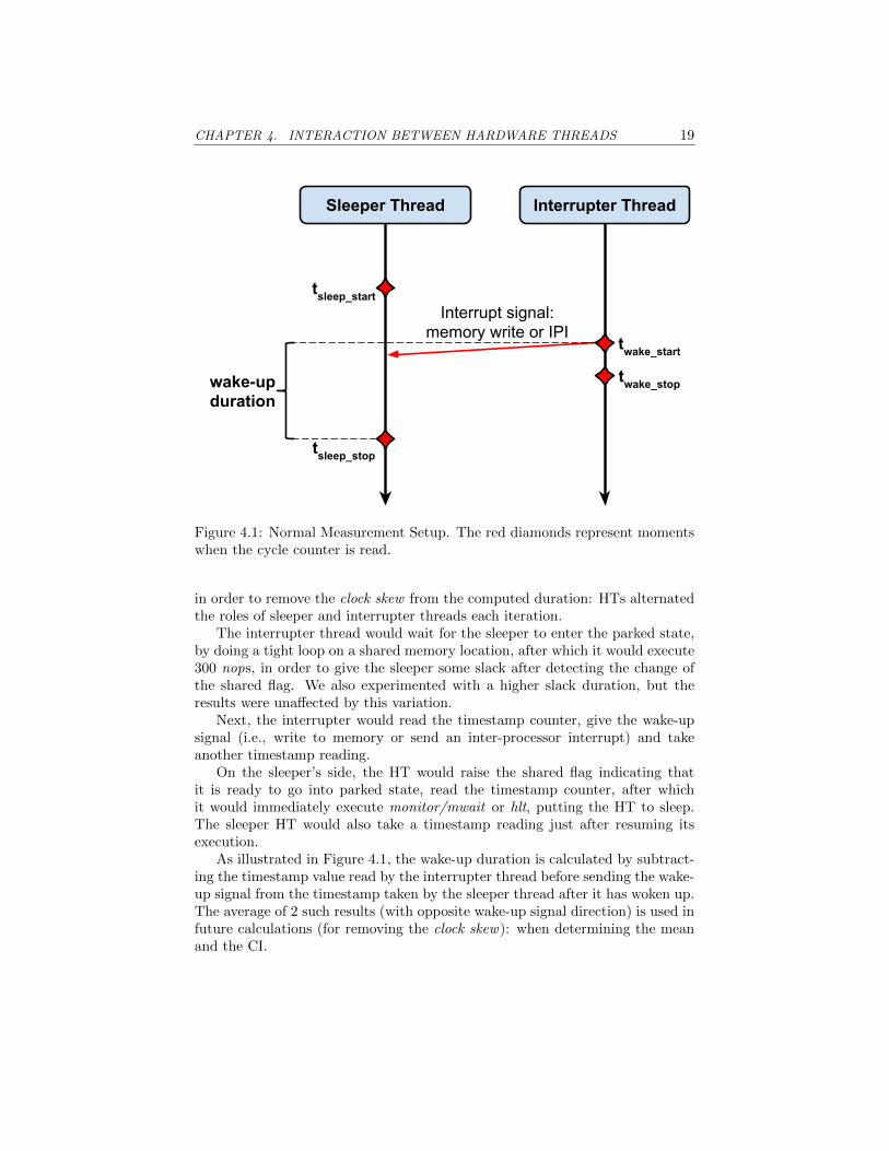
Figure 4.1 represents a diagram of the first measurement setup which we em-ployed. The 2 hardware threads executed 240 iterations, out of which the firstand last 10 were discarded. As the start and stop timestamps are taken bydifferent HTs with unsynchronized timestamp counters, we needed 2 iterations
CHAPTER 4. INTERACTION BETWEEN HARDWARE THREADS 19
Sleeper Thread Interrupter Thread
tsleep_start
tsleep_stop
twake_start
twake_stopwake-up duration
Interrupt signal:memory write or IPI
Figure 4.1: Normal Measurement Setup. The red diamonds represent momentswhen the cycle counter is read.
in order to remove the clock skew from the computed duration: HTs alternatedthe roles of sleeper and interrupter threads each iteration.
The interrupter thread would wait for the sleeper to enter the parked state,by doing a tight loop on a shared memory location, after which it would execute300 nops, in order to give the sleeper some slack after detecting the change ofthe shared flag. We also experimented with a higher slack duration, but theresults were unaffected by this variation.
Next, the interrupter would read the timestamp counter, give the wake-upsignal (i.e., write to memory or send an inter-processor interrupt) and takeanother timestamp reading.
On the sleeper’s side, the HT would raise the shared flag indicating thatit is ready to go into parked state, read the timestamp counter, after whichit would immediately execute monitor/mwait or hlt, putting the HT to sleep.The sleeper HT would also take a timestamp reading just after resuming itsexecution.
As illustrated in Figure 4.1, the wake-up duration is calculated by subtract-ing the timestamp value read by the interrupter thread before sending the wake-up signal from the timestamp taken by the sleeper thread after it has woken up.The average of 2 such results (with opposite wake-up signal direction) is used infuture calculations (for removing the clock skew): when determining the meanand the CI.

CHAPTER 4. INTERACTION BETWEEN HARDWARE THREADS 20
Normal Measurement with Hyper-Threading enabled
The results, for the cases where Hyper-Threading was enabled, are displayedin Figures 4.2 and 4.3: the number written in the cell at the intersection be-tween X (on the horizontal axis) and Y (on the vertical axis) corresponds tothe benchmark being run with HTs X and Y. The difference between the sce-narios represented by these figures is that the former (i.e., Figure 4.2) usedmonitor/mwait as the parking mechanism, while the latter (i.e., Figure 4.3)employed hlt.
Looking at Figures 4.2b and 4.3b we see that the 95% confidence intervalsare tight around the means, consisting of less than 24 cycles for average valueshigher than 1200 cycles (i.e., less than 2% of the means).
The numbers on both axes represent APIC IDs: hardware identifiers ofeach HT. As noted in Section 4.4, the benchmarked CPU had 4 cores, eachhaving 2-way SMT. The APIC IDs encode, in their binary representation, thehierarchical position of the associated HT: starting from the least significant bit,this ID is composed of groups of bits identifying the SMT lane in the physicalcore, the physical core in the socket and so on. As our experiment considers asingle socket system, we are only interested in separating the HT identifier fromthe rest of the APIC ID, which (in this case) consists of a single bit (enoughfor a 2-way SMT processor). For example, the HT with APIC ID 510 = 1012corresponds to the SMT lane with ID 1 and the core with ID 210 = 102: the2nd HT of the 3rd core, since all IDs are 0-based.
Knowing that the HTs with APIC IDs 0 & 1, 2 & 3, 4 & 5, 6 & 7 sharethe same physical core, we can see from the results that tightly coupled SMTlanes exhibited a longer wake-up duration. At first, we thought this was causedby the fact that, while the sleeper HT was waking up, the interrupter HT (whowas transitioning into the sleeper role for the next iteration) was going to sleep:this behavior could have generated contention in the in-hardware mechanismsused for resource allocation (for example, the partitioned resources mentioned inSection 2.2). That supposition proved to be false, as no change in the observedbehavior was witnessed when adding a nop loop before the interrupter threadwent to sleep (for the next iteration).
Looking at the big picture, what we saw was that when both tightly-coupledSMT lanes executed the benchmark they were affected by a longer wake-upduration. However, this was not the case when one of these lanes was run-ning normal Barrelfish code. Our guess is that the reason for the observedbehavior was the nature of executed machine-level instructions and/or the waycache utilization: we knew beforehand that HTs belonging to the same physi-cal core provide the largest throughput when executing orthogonal operations(for example, one does integer additions while the other executes floating-pointoperations).
Lastly, but probably the most important takeaway from the data displayedin Figures 4.2 and 4.3, we can derive the number of cycles needed by an HT inorder to resume from sleep:
• ≈ 1250 cycles, for a monitor/mwait induced sleep;

CHAPTER 4. INTERACTION BETWEEN HARDWARE THREADS 21
0 1 2 3 4 5 6 7APIC ID
76
54
32
10
AP
IC ID
1235.281236.081232.561249.641240.281235.721325.88
1238.161239.681233.161226.721244.721236.48 1325.88
1213.681232.921219.241218.561273.72 1236.481235.72
1215.601234.161229.601220.36 1273.721244.721240.28
1214.161214.641295.68 1220.361218.561226.721249.64
1220.081220.20 1295.681229.601219.241233.161232.56
1280.44 1220.201214.641234.161232.921239.681236.08
1280.441220.081214.161215.601213.681238.161235.281225.00
1250.00
1275.00
1300.00
1325.00
(a) Duration from wake start to sleep stop (cycles)
0 1 2 3 4 5 6 7APIC ID
76
54
32
10
AP
IC ID
12.91 12.29 7.66 9.69 16.84 9.98 22.78
11.33 11.30 9.00 8.82 13.29 9.25 22.78
6.99 22.10 7.39 7.08 19.82 9.25 9.98
5.99 19.86 12.44 8.19 19.82 13.29 16.84
8.86 12.40 23.07 8.19 7.08 8.82 9.69
9.86 12.49 23.07 12.44 7.39 9.00 7.66
21.51 12.49 12.40 19.86 22.10 11.30 12.29
21.51 9.86 8.86 5.99 6.99 11.33 12.918.00
12.00
16.00
20.00
(b) 95% CI for Figure 4.2a
Figure 4.2: Normal measurement of vacherin’s wake-up duration from sleepinduced by mwait (Hyper-Threading enabled)

CHAPTER 4. INTERACTION BETWEEN HARDWARE THREADS 22
0 1 2 3 4 5 6 7APIC ID
76
54
32
10
AP
IC ID
1776.481759.681756.801771.481788.881775.521991.44
1776.601764.801762.281783.001801.601767.64 1991.44
1747.601765.761755.041782.481981.64 1767.641775.52
1778.921749.921761.641752.44 1981.641801.601788.88
1738.521745.401925.20 1752.441782.481783.001771.48
1764.081752.24 1925.201761.641755.041762.281756.80
1912.52 1752.241745.401749.921765.761764.801759.68
1912.521764.081738.521778.921747.601776.601776.48 1750.00
1800.00
1850.00
1900.00
1950.00
(a) Duration from wake start to sleep stop (cycles)
0 1 2 3 4 5 6 7APIC ID
76
54
32
10
AP
IC ID
9.49 9.32 5.77 9.38 17.41 10.65 2.78
11.16 12.03 5.33 16.96 16.10 7.12 2.78
7.56 22.42 6.75 15.35 2.22 7.12 10.65
11.65 11.28 11.37 5.48 2.22 16.10 17.41
5.81 11.80 6.63 5.48 15.35 16.96 9.38
11.70 15.30 6.63 11.37 6.75 5.33 5.77
8.00 15.30 11.80 11.28 22.42 12.03 9.32
8.00 11.70 5.81 11.65 7.56 11.16 9.494.00
8.00
12.00
16.00
20.00
(b) 95% CI for Figure 4.3a
Figure 4.3: Normal measurement of vacherin’s wake-up duration from sleepinduced by hlt (Hyper-Threading enabled)

CHAPTER 4. INTERACTION BETWEEN HARDWARE THREADS 23
• ≈ 1800 cycles, for an HT parked via hlt.
Although not displayed in the previously referenced figures, we were alsoable to determine the cost of sending a wake-up signal (i.e., a memory stores inthe case of monitor/mwait and an IPI in the case of hlt):
• ≈ 0 cycles, for monitor/mwait ;
• ≈ 550 cycles, for hlt.
This penalty imposed on the interrupter thread was computed by subtractingtwake start from twake stop (see Figure 4.1).
Normal Measurement with Hyper-Threading disabled
In order to see how Hyper-Threading affects wake-up duration, we disabled thisfeature in the BIOS and ran the experiment in the same, normal measurement,setup.
The first thing that we notice when analyzing Figures 4.4 & 4.5 in comparisonwith Figures 4.2 & 4.3 is the more stable behavior of the system, both in terms ofthe range of observed wake-up durations (for different HT pairs) and in terms ofthe confidence intervals: the most clear indication is that the 95% CI is between4× and 20× smaller. Also, there are no pairs of cores which exhibit distinctivebehavior, like in the case of tightly-coupled HTs (when Hyper-Threading wasenabled).
The main reason why we disabled Hyper-Threading was to see the effect onwake-up duration, which, in this case, is:
• ≈ 1160 cycles, for monitor/mwait ;
• ≈ 1590 cycles, for hlt.
The values are a bit lower (1160 vs 1250 and 1590 vs 1800, all values incycles), which can be accounted for by the contention for shared hardware re-sources, in the case where 2-way SMT was enabled.

CHAPTER 4. INTERACTION BETWEEN HARDWARE THREADS 24
0 2 4 6APIC ID
64
20
AP
IC ID
1156.18 1155.86 1160.08
1155.18 1164.34 1160.08
1159.30 1164.34 1155.86
1159.30 1155.18 1156.181156.00
1158.00
1160.00
1162.00
1164.00
(a) Duration from wake start to sleep stop (cycles)
0 2 4 6APIC ID
64
20
AP
IC ID
2.07 2.40 2.23
5.09 3.75 2.23
5.88 3.75 2.40
5.88 5.09 2.072.40
3.20
4.00
4.80
5.60
(b) 95% CI for Figure 4.4a
Figure 4.4: Normal measurement of vacherin’s wake-up duration from sleepinduced by mwait (Hyper-Threading disabled)

CHAPTER 4. INTERACTION BETWEEN HARDWARE THREADS 25
0 2 4 6APIC ID
64
20
AP
IC ID
1590.58 1593.74 1603.96
1586.68 1589.30 1603.96
1575.04 1589.30 1593.74
1575.04 1586.68 1590.581580.00
1585.00
1590.00
1595.00
1600.00
(a) Duration from wake start to sleep stop (cycles)
0 2 4 6APIC ID
64
20
AP
IC ID
1.20 1.32 0.83
1.24 1.31 0.83
1.32 1.31 1.32
1.32 1.24 1.20 0.90
1.00
1.10
1.20
1.30
(b) 95% CI for Figure 4.5a
Figure 4.5: Normal measurement of vacherin’s wake-up duration from sleepinduced by hlt (Hyper-Threading disabled)

CHAPTER 4. INTERACTION BETWEEN HARDWARE THREADS 26
4.1.2 Reduced Measurement Setup
The reduced measurement setup, portrayed in Figure 4.6, represents anothermethod of measuring the synchronization overhead between hardware threads.The main difference when compared to the normal measurement setup is that,this time, only the interrupter thread reads the timestamp counter.
Sleeper Thread Interrupter Thread
sleep start
twake_start
tsleep_stop
wake-up duration
Interrupt signal:memory write or IPI
sleep stopWrite to shared memory
propagates
Figure 4.6: Reduced Measurement Setup. The red diamonds represent momentswhen the cycle counter is read.
The beginning of a measurement round is the same as in the normal setup:the sleeper thread raises a flag (by writing into a memory location shared withthe interrupter thread) and goes to sleep (via monitor/mwait or hlt). Mean-while, the interrupter spins on the shared flag, exiting the loop only after it hasdetected the change. Next, the interrupter performs 300 nops (in order to givethe sleeper some time for releasing hardware resources), reads the timestampcounter (twake start) and sends the interrupting signal (either a memory writeor an IPI, depending on the employed sleeping mechanism). Following, the in-terrupter thread spins on another flag, which will be raised by the sleeper onceit has resumed execution. Finally, after the interrupter exits the second spin-ning loop, it determines the value of tsleep stop by reading (again) the timestampcounter.
Thus, the wake-up duration is computed as tsleep stop − twake start.Since the 2 timestamps have been taken by the same hardware thread, there
is no clock skew and no need to alternate sleeper and interrupter roles betweenthe HTs, in order to determine the wake-up duration. However, as a similarityto the normal measurement setup, we kept the alternating rounds.
We executed 240 rounds for each of the 2 available sleeping mechanisms(monitor/mwait and hlt) and for 2 hardware configurations (Hyper-Threading

CHAPTER 4. INTERACTION BETWEEN HARDWARE THREADS 27
enabled and disabled). These actions were performed for each (unordered) pairof threads, meaning that:
• for HT pair (X, Y ), the 240 rounds for a given sleeping mechanism andhardware configuration generates 120 values for the wake-up duration ofHT X (the rounds in which HT Y was the interrupter) and 120 valuesfor the wake-up duration of HT Y (the rounds in which HT X was theinterrupter);
• in contrast to the normal measurement setup, the reduced setup may (andoften does) yield different values for the wake-up duration of the 2 HTswhich were benchmarked together. Thus, the value placed in the heat-maps at the intersection between x -coordinate X and y-coordinate Y isassociated with HT X (i.e., the sleeper HT). This is the reason for whichthe axes are labeled ”Sleeper APIC ID” and ”Interrupter APIC ID”, asopposed to just ”APIC ID”.
The means and 95% CIs of the computed wake-up durations are presentedin the following paragraphs.
Reduced Measurement with Hyper-Threading enabled
When Hyper-Threading was enabled, we obtained the wake-up duration datadepicted in Figures 4.7 (for monitor/mwait) and 4.8 (for hlt).
A significant amount of noise can be witnessed in the case of sleeping viamonitor/mwait, with noticeable outliers (such as sleeper 5 & interrupters 6 and7, respectively): see the 95% CI in Figure 4.7b. The fact that the noise levelshave not increased for the hlt-based sleeping, when switching from the normalsetup to the reduced one, suggests that memory operations are at fault forthe larger confidence intervals: the biggest difference between the 2 sleepingmechanisms lies in the way in which an HT is resumed (memory write formonitor/mwait and IPI for hlt).
Overall, we notice higher values for the wake-up durations:
• ≈ 1750 cycles, for monitor/mwait ;
• ≈ 2200 cycle, for hlt.
Compared to the values obtained in similar conditions, but by using thenormal measurement setup, we see that the wake-up durations have increasedby 400− 500 cycles. The most probable cause for this effect is the fact that theinterrupter thread spins on a shared variable while waiting for the sleeper HTto resume. Only when this variable is changed by the newly waken thread doesthe interrupter record tsleep stop.

CHAPTER 4. INTERACTION BETWEEN HARDWARE THREADS 28
0 1 2 3 4 5 6 7Sleeper APIC ID
76
54
32
10
Inte
rrup
ter A
PIC
ID1571.081689.241699.561689.921722.681890.401516.56
1649.161635.081660.881707.881725.761879.00 1821.12
1659.001603.281655.281623.081703.08 1781.361787.88
1666.041657.361658.481591.16 1829.202115.121778.04
1677.321641.001676.04 1753.601761.281777.241781.76
1607.121671.00 1783.521766.361758.561780.921783.52
1705.80 1758.161764.521784.041778.761816.481820.60
1768.321726.961722.441747.441748.601778.921780.76
1600.00
1700.00
1800.00
1900.00
2000.00
2100.00
(a) Duration from wake start to sleep stop (cycles)
0 1 2 3 4 5 6 7Sleeper APIC ID
76
54
32
10
Inte
rrup
ter A
PIC
ID
72.28 32.17 42.69 49.81 45.64 349.21 121.92
107.21 57.44 48.58 44.03 46.36 334.73 4.05
46.17 66.10 60.45 76.24 83.41 16.57 18.20
102.88 49.62 55.47 80.10 3.68 465.10 19.15
36.96 55.73 87.94 16.77 17.59 19.06 18.74
48.25 47.62 31.67 17.29 16.27 17.76 17.99
61.16 15.73 14.49 15.75 14.96 14.97 14.99
4.09 17.66 18.10 17.49 18.20 17.21 17.24
80.00
160.00
240.00
320.00
400.00
(b) 95% CI for Figure 4.7a
Figure 4.7: Reduced measurement of vacherin’s wake-up duration from sleepinduced by mwait (Hyper-Threading enabled)

CHAPTER 4. INTERACTION BETWEEN HARDWARE THREADS 29
0 1 2 3 4 5 6 7Sleeper APIC ID
76
54
32
10
Inte
rrup
ter A
PIC
ID2120.162143.882152.962154.242174.242128.562289.52
2075.162153.242101.522164.402178.082182.00 2347.40
2155.002123.562153.122178.282298.32 2190.802202.40
2064.082158.202108.122159.96 2311.362194.402206.96
2133.442154.362261.88 2179.962183.002204.002199.32
2044.162148.48 2322.122192.522167.122203.562186.36
2327.52 2180.562185.562197.762203.802232.122222.08
2299.642142.562139.322183.522155.282187.962181.64
2100.00
2160.00
2220.00
2280.00
2340.00
(a) Duration from wake start to sleep stop (cycles)
0 1 2 3 4 5 6 7Sleeper APIC ID
76
54
32
10
Inte
rrup
ter A
PIC
ID
25.32 26.05 21.90 18.22 20.11 37.07 36.84
17.92 25.31 17.26 22.88 18.13 20.70 9.79
24.03 24.71 18.93 22.82 24.36 22.78 17.81
16.51 25.82 21.01 17.20 23.04 20.87 27.82
17.63 24.47 36.65 16.65 17.33 15.71 19.32
9.45 27.02 1.60 17.49 21.99 19.03 18.26
23.40 19.00 19.42 20.45 18.72 20.26 19.66
16.56 18.28 18.34 18.19 19.39 18.07 25.07
8.00
16.00
24.00
32.00
(b) 95% CI for Figure 4.8a
Figure 4.8: Reduced measurement of vacherin’s wake-up duration from sleepinduced by hlt (Hyper-Threading enabled)

CHAPTER 4. INTERACTION BETWEEN HARDWARE THREADS 30
Reduced Measurement with Hyper-Threading disabled
As we did in the case of the normal measurement setup, we also ran the experi-ments in the reduced setup with Hyper-Threading disabled. The processed datais presented in Figures 4.9 and 4.10.
We again observed an increase in the 95% CI when compared to the ex-periments executed in the normal setup with Hyper-Threading disabled (i.e.,Figures 4.4 and 4.5): these intervals have increased by ≈ 20× (in the case ofmwait) and by ≈ 10× (for hlt). The difference between the 2 factors supportthe idea presented in the previous paragraphs: that spinning on the ”sleep stopflag” is the reason for the increased measured wake-up durations.
These durations are:
• ≈ 1750 cycles, for monitor/mwait ;
• ≈ 1800 cycle, for hlt.
Comparing the effect of Hyper-Threading in the reduced setup, it seems thatthe overhead of the extra spin lock (i.e., the one signaling the sleeper resumingexecution) shadows the difference between waking-up from mwait-induced sleepwhile having Hyper-Threading enabled vs disabled : the wake-up durations arenegligible higher when Hyper-Threading Technology was enabled.
For the hlt-based sleep, enabling 2-way SMT increased the wake-up durationsby about 200 cycles in the normal setup, and by 400 cycles in the reduced setup.This is probably due to the higher cost of doing a tight loop of memory readswhen both HTs of the same core are active.
4.1.3 Cost of HT Synchronization
Taking a step back and looking at the practical differences between the normaland the reduced setups, we see that:
• the normal setup minimizes the amount of non-benchmarked synchroniza-tion between HTs, by only ensuring that the interrupter sends the wake-upsignal after the sleeper has entered the low power state;
• the reduced setup adds extra synchronization inherently included in themeasured durations, but provides the extra benefit of only taking times-tamps from a single hardware thread, which has not just resumed execu-tion.
The benefits provided by the reduced setup on top of those existent in thenormal setup are significantly reduced:
• the CPU that we used for testing features an invariant timestamp counter,meaning that: ”The invariant TSC will run at a constant rate in all ACPIP-, C-. and T-states. [...] the OS may use the TSC for wall clock timerservices” [6].

CHAPTER 4. INTERACTION BETWEEN HARDWARE THREADS 31
0 2 4 6Sleeper APIC ID
64
20
Inte
rrup
ter A
PIC
ID
1694.28 1590.60 1700.76
1685.60 1671.56 1812.20
1702.24 1781.76 1824.00
1792.36 1777.88 1823.40
1600.00
1650.00
1700.00
1750.00
1800.00
(a) Duration from wake start to sleep stop (cycles)
0 2 4 6Sleeper APIC ID
64
20
Inte
rrup
ter A
PIC
ID
56.79 98.90 61.29
60.43 71.77 1.65
59.71 1.14 1.65
1.95 1.52 2.21
20.00
40.00
60.00
80.00
(b) 95% CI for Figure 4.9a
Figure 4.9: Reduced measurement of vacherin’s wake-up duration from sleepinduced by mwait (Hyper-Threading disabled)

CHAPTER 4. INTERACTION BETWEEN HARDWARE THREADS 32
0 2 4 6Sleeper APIC ID
64
20
Inte
rrup
ter A
PIC
ID
1762.12 1781.32 1789.32
1769.80 1788.88 1812.24
1796.44 1807.56 1812.32
1783.04 1786.96 1805.121770.00
1780.00
1790.00
1800.00
1810.00
(a) Duration from wake start to sleep stop (cycles)
0 2 4 6Sleeper APIC ID
64
20
Inte
rrup
ter A
PIC
ID
8.55 15.42 2.40
12.71 9.33 1.54
12.59 4.17 3.02
1.69 1.48 2.02 3.00
6.00
9.00
12.00
15.00
(b) 95% CI for Figure 4.10a
Figure 4.10: Reduced measurement of vacherin’s wake-up duration from sleepinduced by hlt (Hyper-Threading disabled)

CHAPTER 4. INTERACTION BETWEEN HARDWARE THREADS 33
• as stated before, because the timestamp counters of the sleeper and the in-terrupter threads may not be synchronized, we alternate the roles betweenthe 2 HTs and use 2 measurements in order to compute a single wake-upduration value (as described at the beginning of Subsection 4.1.1).
Thus, in conclusion, the wake-up durations that we are going to use in theremainder of this Thesis are the ones determined via the normal measurementsetup. These are summarized in Table 4.1.
Table 4.1: Wake-up durations from sleep induced via monitor/mwait and hlt,with Hyper-Threading Technology enabled and disabled. All values representthe number of cycles expected to elapse after the wake-up signal is sent anduntil the hardware thread resumes execution.
Sleeping MechanismHyper-Threading
HTT enabled HTT disabled
monitor/mwait 1250 1160hlt 1800 1590
4.2 The Fhourstones Benchmark
So far in this Chapter, we have focused on the cost of synchronizing SMTthreads, with a few side remarks regarding consequences of enabling Hyper-Threading. We will now move on to looking at performance related effects ofusing multiple hardware threads.
For this purpose, we plan on using the Fhourstones benchmark [12]. This isa single-threaded integer benchmark which does an alpha-beta search in orderto solve the game of Connect-4. It is (or was, at least, at some point) includedin the Phoronix Test Suite [8].
We think Fhourstones is a good candidate for a benchmarking program sinceit’s workload is CPU bound and does not employ floating-point operations. Theamount of required memory for solving a 7× 6 board is about 64 MB, which isalmost entirely used for storing a transposition table.
When executing an instance of Fhourstones, we first run 3 warm-up iter-ations, by starting to search for a strategy to solve the game beginning at agiven state (i.e., we make a couple of moves, as opposed to leaving the boardcompletely empty). Afterwards, the Connect-4 game is solved, starting froman empty board. The measurements from the final (i.e., 4th) iteration are usedwhen reporting the results.
Overview of the executed experiments
The outcomes of our experiments are depicted, in a concise manner, in Fig-ure 4.11. The vertical axis shows the average number of kilo-positions explored

CHAPTER 4. INTERACTION BETWEEN HARDWARE THREADS 34
0 | 1 | 2 0 & 1 0 & 2[mwait: 1]
0[mwait: 2]
0[mwait: 0]
1[hlt: 1]
0[hlt: 2]
0[hlt: 0]
1[no ht]0 | 2
[no ht]0 & 2
benchmark runs
0
2000
4000
6000
8000
10000
kpos
/sec
APIC ID012
Figure 4.11: The results of running different Fhourstones-based experiments.The values on the vertical axis represent the number of kilo-positions of theConnect-4 game processed per second. Beneath the horizontal axis, there arelabels identifying each experiment: the meaning of these labels is explained inthe present Section.

CHAPTER 4. INTERACTION BETWEEN HARDWARE THREADS 35
by Fhourstones in each second, while the horizontal axis gives details about theexperiments which we ran. When nothing is mentioned about an HT, it can beassumed that the HT in question was executing the usual Barrelfish domains(details in Section 2.3) on top of a standard CPU Driver. Also, by default,Hyper-Threading was turned on.
Regarding the format used to declare the conditions in which an experimentwas executed:
• ’x | y’ → HTs with APIC IDs x and y were used for the same type ofexperiment, but not at the same time (i.e., 2 different experiments wereexecuted, one for HT x and one for HT y);
• ’x & y’ → HTs with APIC IDs x and y were simultaneously used in thesame experiment;
• ’[mwait: x]’ → the HT with APIC ID x was put to sleep by using moni-tor/mwait ;
• ’[hlt: x]’ → the HT with APIC ID x was put to sleep by using hlt ;
• ’[no ht]’ → Hyper-Threading Technology was disabled.
To make everything crystal clear, the experiments which we employed are(starting from the left of Figure 4.11):
1. ’0 | 1 | 2’ → we ran Fhourstones on the HTs with APIC IDs 0, 1, and 2,respectively, and not at the same time, but in subsequent runs.
2. ’0 & 1’ → 2 (independent) instances of Fhourstones were executed, at thesame time, on HTs 0 and 1;
3. ’0 & 2’ → same as above, but by using HTs 0 and 2;
4. ’[mwait: 1]
0’ → ran Fhourstones on HT 0, while HT 1 was parked using
monitor/mwait (the other HTs were running normal instances of Bar-relfish, as detailed in a previous paragraph of this Section);
5. ’[mwait: 2]
0’→ same as above, but with HT 2 being the sleeping thread;
6. ’[mwait: 0]
1’ → same as experiment 4, but with the roles of the 2 HTs
(i.e., 0 and 1) being reversed;
7. ’[hlt: 1]
0’ → same as experiment 4, with hlt as the sleeping mechanism,
instead of monitor/mwait ;
8. ’[hlt: 2]
0’ → same as experiment 5, with hlt instead of monitor/mwait ;

CHAPTER 4. INTERACTION BETWEEN HARDWARE THREADS 36
9. ’[hlt: 0]
1’→ variation of experiment 6, with hlt instead of monitor/mwait ;
10. ’[no ht]0 | 2
’ → executed a Fhourstones on each of HTs 0 and 2, subse-
quently, not at the same time, and with Hyper-Threading disabled ;
11. ’[no ht]0 & 2
’ → same as above, but the 2 Fhourstones instances (1 on each
HT) were executed simultaneously.
Conclusions based on the data gathered from Fhourstones experi-ments
The reason why we employed such a variety of Fhourstones-based experimentsis that we wanted to look from different angles at the way in which Hyper-Threading affects performance.
Thus, the first observation that we make is that enabling Hyper-Threadingreduces performance of an HT to about 2 thirds of what an HT can achieve ina similar context, but with Hyper-Threading disabled. This is true regardlesswhether the 2 HTs sharing the same physical core execute an identical workloador a different one: there is no difference when HTs 0 and 1 executed Fhourstonesinstances simultaneously vs. when only one of the 2 HTs executed Fhourstonesand the other one was running the default Barrelfish domains.
Thankfully, however, if one of the HTs of a core is parked by using eitherof monitor/mwait or hlt, the remaining HT (on that physical core) gets a per-formance boost making it on par with the single-HT core (i.e., the core whenHyper-Threading is disabled): this means that, in practice, we can switch be-tween having or not the advantages and disadvantages of Hyper-Threading atruntime, under the control of the OS.
While it is true that enabling Hyper-Threading (and leaving all the HTs on)takes away a third of the processing power of each HT, the total throughputof each physical core increases by up to 33%, provided that the workload onthat core is parallelized enough so that both HTs can work independently. Thismeans that, depending on the degree of parallelism, the performance observedwhen enabling Hyper-Threading can be between 66% and 133% of a single-HTcore. Note that, by relying on monitor/mwait and hlt, the lower bound canbe increased to 100% of the single-HT core performance: the insufficiently useof the parallel HTs can be detected and one of the HTs can be put to sleep(awaiting to be resumed when the workload can be better parallelized).
In Section 4.1 we explored the differences between monitor/mwait and hltand determined that the former is a better candidate, since the duration ofwaking-up a sleeping HT and the cost of sending the wake-up signal were bothsmaller when compared to the latter option. Based on that finding, and takinginto consideration that the effects of both sleeping mechanisms were indistin-guishable in our Fhourstones-based experiments, we further recommend the useof monitor/mwait, when possible.

CHAPTER 4. INTERACTION BETWEEN HARDWARE THREADS 37
Finally, we would like to point out that, based on experiments ’[mwait: 1]
0’
and ’[mwait: 0]
1’ (and, of course, their hlt-based variations), the idea of using
HT switching as an alternative to the classic context switching mechanism seemspromising: when only one of the 2 per-core HTs is awake there is no differencein processing power when compared to the situation of having Hyper-Threadingdisabled on that core. The thing left to consider is how much time is takes to dothe context switch, which we will explore in the next Section (i.e., Section 4.3).
4.3 Context Switching
Moving forward, we are interested in the duration of switching the virtual ad-dress space (i.e., VAS ) of a hardware thread. For this, we executed a specialbenchmarking program and measured the operations of interest:
• ’NOP syscall’ → the time it takes to go in and out of the kernel forexecuting a syscall which does nothing;
• ’cap invocation’→ the duration of dropping into the kernel via a capabilityinvocation syscall, determining the type of invocation (which, in this case,is a nop) and returning from the syscall. Note that the duration of ’NOPsyscall’ is included in ’cap invocation’. Also, as a side remark, capabilityinvocations are normal Barrelfish syscalls which involve operations linkedto capabilities;
• ’VAS switch’→ the duration of performing a virtual address space switch,assuming that the target address space has already been constructed.Again, note that this measurement includes the duration of a ’cap invoca-tion’, since the interface to a context switch is represented by a capabilityinvocation;
• ’VAS tagged switch’ → as the previous operation, but with TLB (i.e.,translation lookaside buffer) tagging enabled: TLB entries are tagged witha virtual address space identifier and are only considered valid if these IDsmatch the currently used virtual address space. The sought for advan-tage is that some entries in the TLB will not be replaced when switchingbetween multiple address spaces and, thus, the number of compulsorycache misses is minimized. In case TLB tagging is not enabled (and noother alternative mechanism is employed), then the entire TLB needs tobe flushed upon a context switch.
The evaluation that we carried out was composed of a single-threaded do-main, running on an HT and performing 100 warm-up iterations and 10000measured iterations for each operation. For the latter 2 operations (i.e., ’VASswitch’ and ’VAS tagged switch’) a secondary virtual address space was createdand all the mapping from the domain’s initial address space were copied into

CHAPTER 4. INTERACTION BETWEEN HARDWARE THREADS 38
Table 4.2: Durations (top) and 95% confidence intervals (bottom) of virtualaddress space context switching related operations. ”NOP syscall” and ”capinvocation” are included in ”VAS switch” and ”VAS tagged switch”.
Operations Durations (cycles)
HTTOperation NOP
syscallcap
invocationVAS
switchVAS
tagged switchenabled 169 321 805 683disabled 135 202 626 455
95% Confidence Interval of Operations Durations
HTTOperation NOP
syscallcap
invocationVAS
switchVAS
tagged switchenabled 0.17 0.29 0.41 0.41disabled 0.02 0.06 0.08 0.06
enabled disabledHyper-Threading Technology
0
100
200
300
400
500
600
700
800
900
dura
tion
(cyc
les)
OperationNOP syscallcap invocationVAS switchVAS tagged switch
Figure 4.12: Visual representation of the data in Table 4.2: durations of virtualaddress space context switch related operation. Confidence interval are toosmall to be visible in this plot.

CHAPTER 4. INTERACTION BETWEEN HARDWARE THREADS 39
the new one. The VAS creation was carried out before the warm-up phase andan iteration meant that the domain switched from the initial address space tothe new one, and back. The duration was measured for each of the 2 transi-tions, but we only report the data for switching from the new VAS to the initialone: the values were about the same and including the durations for the othertransition would have just polluted our tables and plot, without generating anynoticeable insight.
The recorded durations are depicted in Table 4.2 (for an exact overview ofthe values) and in Figure 4.12 (for facilitating relative analysis). As can beobserved, we performed the previously described benchmarking process under2 conditions: with Hyper-Threading (i.e., HTT) enabled and disabled.
First of all, we see that the durations are smaller and the 95% confidenceintervals tighter in the case in which Hyper-Threading was disabled. This hascome to be expected, considering the previous observations which we madein this Chapter, regarding the effect of using Hyper-Threading. Also, we canclearly see that enabling TLB tagging helps improve the duration of a contextswitch.
However, far more important is to compare, in the context of Hyper-Threadingbeing enabled, the duration of a virtual address space switching (at most 805 cy-cles) with the wake-up duration of a hardware thread (at least 1250 cycles).Looking at the numbers, it is pretty clear that we would face a 55% penaltyduring each context switch if we implemented most of the alternatives proposedat the beginning of Chapter 4 (the alternatives which involve running a singleHT at any given time, and alternating them as a form of context switching).
4.4 Hardware Details
All the experiments presented in this Chapter have been executed on the vacherinmachine, which features an Intel R© Xeon R© CPU E3-1245 v3 with the followingcharacteristics:
• part of the Haswell processor microarchitecture;
• 3.40 GHz base CPU frequency;
• 4 cores;
• per core L1 caches:
– 32 KB 8-way set associative instruction cache;
– 32 KB 8-way set associative data cache.
• per core L2 cache: 256 KB 8-way set associative;
• shared L3 cache: 8 MB 16-way set associative;
• 2-way SMT via Intel R© Hyper-Threading Technology;

CHAPTER 4. INTERACTION BETWEEN HARDWARE THREADS 40
• although the processor should support Intel R© Turbo Boost Technology,we found this feature to be unavailable on our system:
– the associated BIOS option is grayed out;
– executing ”cat /sys/devices/system/cpu/intel pstate/no turbo”on Ubuntu returns ”1”;
– the output of the cpuid command (also on Ubuntu) includes ”IntelTurbo Boost Technology = false”.
4.5 Conclusions on Hardware Threads Interac-tion
We have commenced this Chapter with a set of questions regarding the costof synchronizing SMT threads, their trade-offs and the flexibility of managingthem. By running a variety of benchmarking programs on top of our target hard-ware platform, the vacherin machine (see Section 4.4 for hardware details), wewere able to learn the most important characteristics of Intel Hyper-Threading.
Thus, we have come to the conclusion that it takes 1250 cycles for a sleepinghardware thread to resume execution when it was parked via monitor/mwaitand 1800 cycles when it was put to sleep by using hlt.
The next thing that we did was to use the Fhourstones [12] to help usunderstand what penalty does an SMT thread incur when it shares the physicalcore. It turns out that, on vacherin, each of the 2 hardware threads of a core isable to provide at least 66% of the single-threaded core throughput. This meansthat, while single-threaded performance goes down by 33%, the total (parallel)core throughput increases by 33% (depending on the inherent and exploitedparallelism of the workload). Note that all percentages discussed in this Sectionare relative to the single-threaded core (i.e., with Hyper-Threading turned off),unless otherwise stated.
Another aspect which we observed was that, enabling Hyper-Threading andparking one of the 2 SMT lanes (via either monitor/mwait or hlt) yielded thesame performance on the hardware thread that remained awake as if the latterHT was the only one on that physical core (i.e., as if Hyper-Threading wasturned off).
The last thing that we looked at in this Chapter was the cost of performinga context switch (i.e., a change of virtual address space). This is importantbecause some of the HT management models which we were planning to imple-ment, as stated at the begging of the Chapter, would have used HT synchro-nization as a way of switching between tasks.
Sadly, the cost of doing a context switch (roughly 805 cycles, without usingTLB tagging) is substantially less then what we would have to pay (in terms ofwasted cycles) for resuming a sleeping hardware thread.
Based on all the aspects related to Hyper-Threading which we uncoveredin this Chapter, it makes sense to conclude that, from all the proposed OS

CHAPTER 4. INTERACTION BETWEEN HARDWARE THREADS 41
models for managing SMT lanes, only the first and the last one presented atthe beginning of this Chapter make sense. These are:
• the baseline naive approach, of running a CPU driver on each SMT thread;
• the idea of running multiple user-space SMT threads at the same time,but only allowing at most one in the kernel at any given time (i.e., 2 HTssharing a single CPU Driver).
The discarded models (i.e., 1. dedicated SMT threads for kernel and user-s-pace; 2. SMT threads as caches for user-space dispatcher contexts, with only oneactive at a time; and 3. dedicated SMT thread for the monitor) are left asidebecause it takes less time to perform a normal context switch (either betweenuser-space and kernel or between 2 different virtual address spaces).
The following chapters will tackle the challenges of implementing the 2 re-maining approaches and will evaluate their advantages and disadvantages.

Chapter 5
Multi-HT CPU Driver
Based on the proposed HT models and findings presented in Chapter 4, we willdedicate this Chapter to looking into the necessary CPU Driver changes, inorder to accommodate the management of multiple hardware threads.
5.1 Sharing a Kernel
There are a number of decisions that need to be made when attempting to sharea single CPU Driver between multiple HTs, and we will point these out in thisintroductory Section. As naming conventions, we will use the terms:
• BSHT (i.e., BootStrap Hardware Thread) → the first hardware thread ofa CPU Driver, which is also the HT that initialized the CPU Driver;
• APHT (i.e., APplication Hardware Thread)→ secondary hardware threads,which boot in an already initialized CPU Driver.
Firstly, as one can predict given our discussion of Peters et al.’s paper inSection 3.3, we will adopt the invariant of having at most 1 hardware threadexecuting CPU Driver code at any given time. This decision is based mostlyon the desire to facilitate a future formal proving process of the CPU Driver’scorrectness, and very little on our belief that one BIG-kernel lock is the bestsolution, even for a microkernel, in terms of performance. Nevertheless, thebounded execution (in terms of duration) of most kernel operations (as shownin Figure 5.1) supports the single kernel lock approach, as an HT will generallywait at most a bounded period of time before successfully acquiring the lock.
Given the decision of only allowing exclusive access into the kernel to eachHT, we need to adopt a model for how the kernel stack (or stacks) will operate:this problem is tackled in Section 5.2. We need to also decide on how to enforcethe exclusive access (Section 5.3) and what operations need to be carried out atthe kernel’s entry points (Sections 5.4, 5.5 and 5.6).
After all these are set up, we will detail how was the core booting procedureadapted in order to boot an APHT. This is done in Section 5.7, with the goal
42

CHAPTER 5. MULTI-HT CPU DRIVER 43
0 200 400 600 800 1000 1200 1400 1600Duration (cycles)
0.0
0.2
0.4
0.6
0.8
1.0
Per
cent
age
Figure 5.1: Cumulative histogram of the quickest 99% of the measured syscallsand interrupt & exception handlings. Barrelfish was in its idle state when thesemeasurements were taken. Also, we would like to point out that the remainder1% of syscalls took much longer (up to 12, 359, 892 cycles): these are operationswhich process an arbitrary amount of data (e.g., setting up a virtual addressspace) whose implementation could be converted to portions of code executingin bounded time, but are currently implemented to run in a single stage.

CHAPTER 5. MULTI-HT CPU DRIVER 44
(for now) of being able to get a secondary HT into an existing CPU Driver, afterwhich the APHT in question will leave the kernel and go to sleep. The workwhich extends the capabilities of an APHT to being able to execute user-spacedomains is presented in Chapter 6.
We mentioned that the CPU Driver will be shared by multiple HTs, whichmeans that the kernel’s data will be also shared. While this is fine for mostof the kernel’s data structures, some of them are tied to a specific hardwarethread. Thus, for each HT, we have an HTCB (i.e., hardware thread controlblock), meant to encompass the HT-specific data. The most important membersof the HTCB are presented in Section 5.8. This section is placed towards theend of the Chapter in order to ease the motivation regarding why somethinghas been added (or not) to the HTCB.
5.2 The Kernel Stacks
When there are multiple hardware threads sharing the same kernel, but neveraccessing it at the same time, there are two main approaches one can takeregarding stack management:
1. have a shared stack, ensuring an HT can gain exclusive access to it;
2. use separate, per-HT, stacks.
In between these two options, there are additional alternatives which tendtowards one side or to the other: sharing a stack sometimes and having separatestacks other times.
Our first decision was to choose one of the two main trends: weighting inthe reduced memory footprint when using a single, shared stack, we chose thisapproach. Using multiple stacks would have eased the implementation, but weconsidered runtime performance and a clean design more important aspects.
The simplest manner of ensuring that at most one HT can access the sharedkernel stack at any given time is to require that the HT in question holds thekernel lock (details about the lock in Section 5.3). Thus, the correct order ofthese operations is to first acquire the kernel lock and, only afterwards, to makeuse of the stack.
From the 3 kernel entry points, only one saves data on the stack before givingcontrol to the kernel code: the interrupts and exceptions entry point (expandedupon in Section 5.6). Since the amount of saved data is insignificant compared tothe default Barrelfish kernel stack size (40 bytes, or 48 bytes for some exceptions,vs 16 kB), we decided to use small per-HT stacks during periods when stackoperations could not be overlapped with the kernel lock being held by the HT.
A similar situation, which also requires per-HT kernel stacks, is the actionof exiting the kernel and returning to user-space via iretq. The reason for thisis that the iretq processor instruction pops some register values (as shown inFigure 5.2) from the stack. Since an HT releases the kernel lock before returningto user-space (via iretq, for our current scenario of interest), a race-condition is

CHAPTER 5. MULTI-HT CPU DRIVER 45
created between the exiting HT looking up data on the shared stack and anotherentering HT which modifies the stack by pushing data onto it.
In both cases presented in the previous 2 paragraphs, the solution we choseand implemented is to switch between the private and shared stacks, by changingthe RSP register and copying data from the old stack to the new one. Forexample, in the situation of exiting the kernel via iretq, we set the RSP registerto point to the private stack, copy over the stack frame depicted in Figure 5.2(in Section 5.6) from the shared stack to the private one, release the kernel lockand, in the end, execute iretq.
5.3 The BIG-Kernel Lock
At this point, the idea of using a lock around the kernel comes natural, as a wayof ensuring exclusive access to the CPU Driver for a single hardware thread ata time.
We started by using a spinlock, implemented as a loop that executes pauseafter failing to acquire the lock (and before retrying). The usage of pause and theplacement of the locking variable in an 128 bytes block of memory (which is also128-byte aligned) are techniques recommended by Intel in their OptimizationReference Manual [5].
For the actual lock acquiring, we use an atomic compare and exchange as-sembly instruction (i.e., lock cmpxchg).
The lock is implemented entirely in assembly and takes a single registerargument: the address of the HT’s HTCB, in RBX. Because we opted for asingle kernel stack per CPU Driver, which may not be used before acquiring thekernel lock, the address to jump to after the lock has been acquired is storedin the HTCB (and is set before starting the execution of the lock acquiringprocedure). Also, since kernel code preceding the lock acquiring procedure mustuse some registers (e.g., saves a set of registers and uses them to determine theaddress of the HTCB), the lock acquiring procedure assumes that it can clobberthe RAX register.
By using the previously described locking interface, we were able to abstractaway the actual implementation of the lock: replacing the spinlock with a queue-based lock may requires at most minimal changes to the kernel entry points’code. Regarding this replacement, the person making the change needs to ensurethat all the memory stores performed by an HT exiting the kernel are seen byany other HT before they see the lock being released: this ensures that a newHT entering the CPU Driver will find the shared kernel state in a quiescentstate.
5.4 The CPU Driver’s Boot Entry Point
When booting a Barrelfish CPU Driver, the first kernel code executed by ahardware thread is the one in boot.S. Because the memory location of the

CHAPTER 5. MULTI-HT CPU DRIVER 46
APIC ID may not be mapped in yet, but thanks to the fact that most registersare not used for other purposes, we retrieve the APIC ID by using the cpuidassembly instruction:
1. EAX ← 0x0B;
2. execute cpuid ;
3. the APIC ID is stored in EDX;
4. the values of EAX, EBX and EDX have been modified to store otherinformation provided by the cpuid ’s 0BH leaf.
The HT’s index in the kernel is derived by selecting a suffix (i..e, a substringcontaining the least significant bits) of the APIC ID, according to a compile-timespecified variable (i.e., a define):
• NUM HTS PER KERNEL is the name of the constant indicating themaximum number of HTs a CPU Driver should be able to accommodate;
• the least significant log 2(NUM HTS PER KERNEL) bits of the APIC IDrepresent the HT’s index in the CPU Driver:
APIC ID = dd . . . d10 = bb . . . b bb . . . . . . . . . . . . . . . . . . . . . . . . . . . . . . . . . . . . . . . b︸ ︷︷ ︸log2(NUM HTS PER KERNEL) bits → HT’s index
2
The reason why we use a suffix of the binary representation of the APICID for HT indexing is that this is the actual format of the APIC ID: theAPIC ID is a concatenation of groups of bits, which identify an SMT laneon a core, a core on a socket and so on, for as many levels as the CPUhierarchy has.
• the APIC ID’s bits not belonging to the HT index (i.e., the ones coloredin red in the previous equation) are the same for all the HTs sharing aCPU Driver.
Knowing the HT index, the size of an HTCB and the base of the arrayholding all the HTCBs of a CPU Driver, it is straight forward to determine theaddress of a hardware thread’s HTCB: the said array of HTCBs is indexed bythe HT index. Note that, by requiring an additional step of indirection (i.e., readthe address of an HTCB from an array containing the addresses of all HTCBs,as opposed to the array containing the HTCBs themselves), the constraint ofhaving all the HTCBs in a statically allocated array can be relaxed: whenbooting an APHT in a CPU Driver, that new hardware thread can fill in (intothe array containing HTCB address) the address of its HTCB.
Following the retrieval of the HTCB’s address, the kernel entry continues byexecuting the lock acquiring procedure presented in Section 5.3.

CHAPTER 5. MULTI-HT CPU DRIVER 47
Listing 5.1: Determining the address of an HT’s HTCB at the syscall entrypoint. A similar method is also used at the IRQ entry point.
1 movq $(X86_64_XAPIC_ID_PHYS + PHYS_TO_MEM_OFFSET), %rbx
23 movl (%rbx), %ebx
4 /* %rbx [31..24] = APIC ID */
56 shrl $24 , %ebx
7 /* NUM_HTS_PER_KERNEL is a power of 2 */
8 andb $(NUM_HTS_PER_KERNEL - 1), %bl
9 /* %rbx [7..0] = HT index */
1011 shlq $3 , %rbx /* %rbx = %rbx * sizeof(uintptr_t) */
12 addq addr_addrs_htcbs (%rip), %rbx
13 movq (%rbx), %rbx
14 /* %rbx = address of HTCB */
5.5 The CPU Driver’s Syscall Entry Point
The main difficulty of adapting the syscall kernel entry point (in entry.S) tosimultaneously accommodate multiple HTs is the scarcity of usable registers atthis point of execution: in the single-HT version of the CPU Driver, all thegeneral purpose registers were used to transfer user-space information to thekernel. In order to overcome this issue, we reserved a general purpose register(RBX ) for HTCB address computation upon kernel entry.
The method used to retrieve the APIC ID in the boot entry point (via cpuid ;see Section 5.4) is not a suitable option in the present context, as it overwrites4 GP registers when reading the APIC ID. However, the syscall entry pointhas the added advantage of only being used after the CPU Driver has beeninitialized. Thus, we can ensure (during the kernel’s initialization) that theAPIC ID’s memory location (i.e., physical address 0xFEE00020) is mapped in.
So, up to this point of the syscall entry point, we managed to read the APICID into RBX and perform a bitwise and in order to isolate the bits of the HT’sindex. The actual assembly code for these operations is presented in Listing 5.1,lines 1− 9.
The next problem is determining the appropriate HTCB, considering thatthe single available register (i.e., RBX ) already contains information (i.e., theindex of the HT, derived from the APIC ID).
While we could have reserved more registers for the purpose of HTCB ad-dress computation, we decided to avoid this solution: a microkernel is (likely)required to service a large number of system calls (typically more than an equiv-alent monolithic kernel) and we wanted to take away as few registers as possiblefrom the set of registers usable for syscall argument transfer. Reducing the num-

CHAPTER 5. MULTI-HT CPU DRIVER 48
Listing 5.2: The initialization of auxiliary variables meant to facilitate the com-putation of an HTCB’s address at the syscall entry point. The same informationis also used at the IRQ entry point.
1 struct htcb htcbs[NUM_HTS_PER_KERNEL ];
2 struct htcb *addrs_htcbs[NUM_HTS_PER_KERNEL ];
3 struct htcb ** addr_addrs_htcbs;
45 /**
6 * addr_addrs_htcbs is initialized by the BSHT in the
7 * CPU Driver ’s ’text_init ’ function:
8 */
9 addr_addrs_htcbs = &addrs_htcbs;
1011 /**
12 * Function used to register an HTCB for the HT with
13 * the given APIC ID.
14 */
15 void htcb_register(struct htcb *htcb , uint8_t apicid)
16 {
17 addrs_htcbs[apicid & (NUM_HTS_PER_KERNEL -1)] = htcb;
18 }
ber of register-stored arguments would have increase stack spilling and wouldhave reduced the amount of data transferable via an LMP syscall.
Given the mentioned constraints and performance trade-offs, we used a num-ber of auxiliary variables and managed to compute the address of the HTCB byreserving a single GP register. These auxiliary variables are shown in Listing 5.2,alongside details regarding their initialization.
Basically, what we did was to use an additional level of indirection (as wassuggested at the end of Section 5.4), by taking advantage of the fact that one ofthe operands for (many) x86 assembly instructions can be referenced in memory.
Thus, we exploited the known pointer size (i.e., 8 bytes on x86-64) in orderto exchange a multiplication (i.e., ”HT index × sizeof (struct HTCB)”) with aleft bit shifting: see line 11 of Listing 5.1. Of course, the bit shifting did notcompensate for the entire multiplication, so we needed 2 additional assemblyinstructions: the ones on lines 12− 13 of Listing 5.1.
5.6 The CPU Driver’s Interrupts and Excep-tions Entry Point
This kernel entry point generated difficulties for our implementation because:
• the context switching mechanism used when an interrupt or an exception

CHAPTER 5. MULTI-HT CPU DRIVER 49
User’s RIP
User’s CS
User’s RFLAGS
User’s RSP
User’s SS
RSP
RSP + 8
RSP + 16
RSP + 24
RSP + 32
Figure 5.2: Top stack frame expected by iretq (i.e., when exiting the kernelafter an exception had occurred). The same stack frame is created when thekernel begins servicing an interrupt or some exceptions. Other exceptions pushan additional error code after the user’s RIP.
occurs pushes a number of registers onto the stack: SS, RSP, RFLAGS,CS and RIP. Thus, before any kernel code is executed, the stack framelooks as in Figure 5.2;
• there is no way to reserve registers, in a manner similar with what we didfor the syscall entry point. This restriction should be easy to understand,given that the hardware does not save any other registers than the onesmentioned at the previous bullet point. Also, when and interrupt or anexception occurs, the CPU immediately switches execution into the kernel,without running any user-space code in-between.
Firstly, we note that, regardless of how we would have chosen to gain aGP register for the purpose of computing the HTCB’s address, there was stillthe need for a private stack upon kernel entry: the hardware pushes data ontothe stack. Thus, we had to give each HT a private stack, large enough toaccommodate the said pushed data.
In order to specify what stack each HT should use, we took advantage ofthe fact that each entry in the IDT (i.e., Interrupt Descriptor Table) specifiesat which address the stack should start when servicing the associated interrup-t/exception. The stack’s address is not placed directly in the IDT entry, butis specified as an index in the ist (i.e., Interrupt Stack Table) field of the TSS(i.e., Task State Segment).
There are 7 slots available in a TSS for specifying different stacks, so, fromthis perspective, we could have used the same TSS for all the HTs. Of course,such a decision would have limited us to at most 7 hardware threads per CPUDriver or force us to allocated another TSS for each 7 HTs (which would haveincreased code complexity without providing a significant advantage).

CHAPTER 5. MULTI-HT CPU DRIVER 50
After weighting the trade-offs, we decided that the added flexibility andsimplicity that comes with having a TSS per HT was more important. If deemedappropriate, reducing all the TSSes to a single one can be implemented afterwe have experimented with different ways of incorporating the idea of multipleHTs in a single CPU Driver.
Having secured per HT kernel stacks (at the beginning of interrupt/excep-tion handling) opens the door for a simple solution for gaining the necessaryGP register in order to compute the HTCB’s address: we push the RBX reg-ister also onto the private stack. Next, the HTCB’s address is determined asexplained in Section 5.5 and the kernel lock is acquired as presented in Sec-tion 5.3. Afterwards, we switch from the private stack to the shared kernelstack (to which we now have exclusive access), making sure we copy the datafrom the old stack to the new one.
As we have pointed out in Section 5.2, the iretq instruction also uses theprivate HT stack, in order to avoid a race condition with another HT enteringthe CPU Driver.
5.7 Booting an Application Hardware Thread
For the purpose of booting an APHT into an existing CPU Driver (which waspreviously initialized by a BSHT) we started from the mechanism which bootsan APP (i.e., application processor; any but the first CPU core which wasstarted when the system had been powered on).
In Barrelfish, the utility used to boot an additional CPU is called corectrland is structured as a collection of subcommands which are passed throughthe command line. For our use case, we added a new subcommand with thefollowing format:
corectrl -m bootapht <APHT Core ID > <BSHT Core ID >
The ”-m” flag tells corectrl to not wait for a monitor message at the end ofthe subcommand’s execution: this is to be expected, since we do not create anew monitor instance.
The 2 arguments (i.e., ”APHT Core ID” and ”BSHT Core ID”) identify theHT to boot and the CPU Driver that will adopt the new APHT (by specifyingthe CPU Driver’s BSHT). These IDs can be determined by examining the outputof the corectrl ’s lscpu subcommand. An example of such an output generated onthe vacherin machine is presented in Listing 5.3. The 2 IDs expected by bootaphtare assigned to CPUs as they are discovered and added into Barrelfish’s SKB(i.e., System Knowledge Base).
When an APP boots (regardless if it is a BSHT or an APHT) it will gothrough an assembly sled meant to initialize some basic hardware functions: forexample, specifying a GDT and enabling paging. The purpose of this assem-bly code is to enable the booting CPU to jump into a CPU Driver and startexecuting it.

CHAPTER 5. MULTI-HT CPU DRIVER 51
Listing 5.3: An example of the output of the ”corectrl lscpu” command onvacherin.The Barrelfish ID is used to identify each CPU Driver, with the valid range ofpossible values being 0− 254: Barrelfish ID 255 means that the associated HTis reserved to be used as an APHT, so it will not have its own CPU Driver, butwill share one with a BSHT (and, possibly, with other APHTs).Note that in this scenario it is considered that there are 2 BSHTs (i.e., CPUs 0and 2) and that each CPU Driver can accomodate a total of 4 HTs.
1 > c o r e c t r l l s cpu2 spawnd . 0 . 0 : spawning /x86 64 / sb in / c o r e c t r l on core 034 CPU 0 : APIC ID=0 PROCESSOR ID=0 BARRELFISH ID=0 ENABLED=15 CPU 1 : APIC ID=2 PROCESSOR ID=1 BARRELFISH ID=255 ENABLED=16 CPU 2 : APIC ID=4 PROCESSOR ID=2 BARRELFISH ID=1 ENABLED=17 CPU 3 : APIC ID=6 PROCESSOR ID=3 BARRELFISH ID=255 ENABLED=18 CPU 4 : APIC ID=1 PROCESSOR ID=4 BARRELFISH ID=255 ENABLED=19 CPU 5 : APIC ID=3 PROCESSOR ID=5 BARRELFISH ID=255 ENABLED=1
10 CPU 6 : APIC ID=5 PROCESSOR ID=6 BARRELFISH ID=255 ENABLED=111 CPU 7 : APIC ID=7 PROCESSOR ID=7 BARRELFISH ID=255 ENABLED=1
In the case of starting an APHT, we need some information from the CPUDriver which will manage this HT:
• the kernel’s entry address→ in order to know from which address to startexecuting kernel code;
• the address of the PML4 page table→ to ensure the same page mappingsfor all the HTs who share a CPU Driver.
These addresses are retrieved by doing an RPC to the monitor of the coreon which corectrl is executing. If that core does not have the same CPU Driveras the target BSHT (i.e., the BSHT with which we want the new APHT toshare the kernel), then the monitor uses the inter-monitor binding to get theinformation from the appropriate monitor : note that the monitor is the user-space extension of the CPU Driver and, for this reason, there is a single monitorper CPU Driver instance.
The initialization code of the CPU Driver is able to discern between a BSHTand an APHT, so it can take the appropriate actions. For example, only theBSHT needs to add a memory mapping for the physical address of the APICID: the APHT gains that mapping by using the same page table.
As mentioned in Section 5.1, we only focus in this Chapter on bringing anAPHT into an already initialized kernel. The way we use an APHT in order toexecute user-space domains is presented in Chapter 6.

CHAPTER 5. MULTI-HT CPU DRIVER 52
5.8 The Hardware Thread Control Block
The HTCB is implemented as a C structure and is meant to encompass eachhardware thread’s specific data. Thus, it seems natural to add in this controlblock the data structures that are directly linked to hardware:
• the HT’s IRQ (i.e., interrupt/exception handling) stack → we discussedthe need for such a stack in Sections 5.2 and 5.6, pointing out that thecontext switching mechanism employed when servicing and interrupt/ex-ception needs to use a stack, without allowing the programmer to ensureexclusive access to the shared kernel stack.
Regarding the IRQ stack size, we mentioned that at most 48 B would bepushed upon kernel entry, when servicing an exception which specifies anerror code. The size which we actually allocated for said stack is slightlylarger: 80 B.
First of all, the hardware expects the IRQ stack to be 16-bytes aligned.Although it can skip part of the stack to ensure this alignment, we thoughtit would be better to prevent this memory loss and declare the memberin the HTCB C structure so that it fulfills the requirement. Thus, wespecified the IRQ stack to be 16-bytes aligned (by using “ attribute
((aligned (16)))”) and also made sure that the size is a multiple of16 bytes (since stacks grow from large addresses to smaller ones).
Secondly, we needed 3 additional slots on the stack for:
– specifying the interrupt/exception’s vector number (used to deter-mine which interrupt/exception had occurred);
– the return address needed when calling a helper function. The saidfunction is responsible with determining the HTCB’s address, acquir-ing the kernel lock and switching to the shared kernel stack;
– saving the RBX register.
So, we need 48 + 3× 8 = 72 bytes, which rounds up (as a multiple of 16)to 80 B.
• the Task State Segment → details that lead to incorporating this datastructure in the HTCB are presented in Section 5.6 and are related to theprivate interrupt/exception handling stack;
• the Global Descriptor Table → Barrelfish uses a static GDT for each CPUDriver, meaning that there is a fixed number of entries which are initializedduring kernel setup. The only entries that may change are the ones relatedto the Local Descriptor Table, when doing a context switch. Thus, havinga private GDT for each HT made it easier to adapt the CPU Driver’slogic, in order to accommodate multiple HTs;
• the Interrupt Descriptor Table → while most of the entries of the IDT arethe same for all the HTs sharing a CPU Driver, there may be situations in

CHAPTER 5. MULTI-HT CPU DRIVER 53
which we want to have an interrupt vector for a specific HT: for example,if an HT goes to sleep via hlt, waking it up requires some other HT tosend an IPI. Thus, we may only want to have the vector (for the wake-upIPI) valid when the HT is actually asleep.
We would like to point out that it is possible to keep some of the previ-ously mentioned HTCB members shared between all the HTs of a CPU Driver.However, we saw 2 main reasons for making them HT-private:
1. Sharing them would have made the process of experimenting with differentCPU Driver designs more difficult, because it may have made it morecumbersome (or even impossible) to implement specific features: consider,for example, if we wanted to enable HT specific interrupt handling andthere was a single IDT per CPU Driver;
2. As there is no need to keep the data (in the previously mentioned datastructures) synchronized between all the HTs (because they are mostlystatic), having to share these structures would have required more signif-icant changes to the way the CPU Driver manages them: for example,having a single GDT has the downside that it must be able to accommo-date distinct TSS and LDT slots for each HT.
Other fields of the HTCB structure are:
• an integer holding the APIC ID → this value is different for each HT;
• a boolean revealing if the HT is also the BSP (i.e., bootstrap processor);
• a pointer to the Dispatcher Control Block of the last dispatched task →HTs simultaneously dispatch different user-space tasks (the implementa-tion of this functionality is detailed in Chapter 6);
• pointers to the currently dispatched task and to the last dispatcher thatmade use of the FPU→ similar motivation as in the previous bullet point;
• a boolean which is only true if the HT is the BSHT;
• slots for saving registers → employed when switching tasks (in the IRQentry point), after the kernel lock had been acquired: the registers areneeded in the loop that copies data from the private stack to the sharedone;
• the base address and the size of the currently used Local Descriptor Table→ in order to prevent the rewriting of the GDT entry referencing theLDT, when the same LDT is used;
• additional boolean and integer fields related to the CPU Driver’s logic →these are used in similar ways as the previously mentioned ones, in thesense that they maintain the state of a given HT.

CHAPTER 5. MULTI-HT CPU DRIVER 54
5.9 Using a Multi-HT CPU Driver
Having a working implementation of a CPU Driver that is able to simultaneouslymanage multiple HTs is not the main target for this Thesis, but rather a toolto be used in order to improve certain aspects of Barrelfish (e.g., increase thethroughput of executed user tasks).
At the beginning of Chapter 4 we have proposed a number of models for usingmultiple HTs which share a CPU Driver. Running experiments and analyzingthe generated data, we have come to the conclusion that only some of the initialmodels make sense, primarily because of the overhead of synchronizing hardwarethreads: Section 4.5 draws the related conclusions.
This Chapter has presented the process of adapting a normal (i.e., single-HT)CPU Driver to a multi-HT context. Based on this capability, and taking intoconsideration the lessons learned in Chapter 4, we will dive into the challengesof exposing the additional processing power to user-space in Chapter 6.

Chapter 6
User Domains on Top of aMulti-HT CPU Driver
In this Chapter, we will continue building upon the multi-HT CPU Driver (pre-sented in Chapter 5) by enabling all the hardware threads to execute user-spacecode. Thus, we will start from the extension of Barrelfish which is able to bootadditional HTs into an already initialized CPU Driver and to perform the neces-sary setup for these HTs. However, the modifications which we have presentedin the previous chapters do not allow these HTs to do any useful work, as theyare halted after executing the kernel initialization code path.
The target which we are now aiming for is to be able to execute multipleuser-space dispatchers at the same time, one on each HT managed by a CPUDriver.
The following Sections focus on specific areas which are of significant impor-tance for running multiple user-domains at the same time, on top of a multi-HTCPU Driver. Towards the end of this Chapter (i.e., in Section 6.6), we discusssome experiments meant to explore differences between our modified version ofBarrelfish and some setups involving single-HT CPU Drivers. Based on the ob-servations generated by said experiments, we propose a scheduler optimizationin Section 6.7.
6.1 Scheduler
The initial plan was to start the implementation by adapting the RR (i.e.,Round-Robin) Scheduler, as it has a simpler logic when compared to the RBED(i.e., Rate-Based Earliest Deadline) Scheduler [3]. Unfortunately, attempting tocompile the CPU Driver wit the RR scheduling policy resulted into a compilationerror: there exists a portion with unimplemented KCB (i.e., Kernel ControlBlock) related logic.
Considering that the missing code is not part of this Thesis’s focus and thatwe would have exchanged the RR Scheduler with the RBED one at some future
55

CHAPTER 6. USER DOMAINS ON TOP OF A MULTI-HT CPU DRIVER 56
moment, we decide to start directly with RBED.Analyzing the logic used by the RBED Scheduler for deciding the next do-
main to be dispatched, the primary multi-HT adaptation issue that stood outwas the time value associated with a particular moment. The problem lies in thefact that each HT has an independent timestamp counter. Considering that thesystem’s real-time clock has a much lower resolution and that there is no directway of determining the time offsets between the HTs (aside from executing adedicated algorithm that uses low-latency thread synchronization operations),we chose to assign the role of the time keeper to the BSHT (i.e., bootstraphardware thread) of each CPU Driver.
Thus, this means that only the BSHT updates the value of the kernel nowvariable, which stores the number of milliseconds since the BSHT booted-up.Compared with implementing and executing a timestamp synchronization algo-rithm, our choice was faster to implement and gave the chance to see how far wecan get with such a simplistic approach: the schedulers implementation includestime-related assertions, so we would have a clear indication if something wentwrong (e.g., missed deadline), in the form of an assertion error. So far, no suchtiming exception has been raised.
In this Section, we have pointed out issues and solutions related to beingable to use the RBED scheduler in a multi-HT CPU Driver. However, a moreinteresting and vast research area is represented by the analysis of potential op-timizations of the scheduling logic. We discussed about this and have dedicateda section to such an optimization proposal (i.e., Section 6.7). However, giventhe time constraints for this Thesis, we decided it is best to leave the scheduleroptimization topic for future work.
6.2 Domains, Dispatchers and Hardware Threads
As explained in Barrelfish’s Architectural Overview Manual [1] (in the sectiondedicated to dispatchers), an application wanting to execute on a particularcore (i.e., on top of a CPU Driver) has to have a dispatcher on that core. Thismeans that the dispatcher represents “the unit of kernel scheduling” and thatdispatchers are owned by a single CPU Driver. As a side-note, we would like topoint out that applications requiring threads in order to implement their logicare not obliged to use multiple dispatchers: green threads are implemented aspart of libbarrelfish.
Transitioning to a context in which a CPU Driver is shared by multiple HTs,we need to address the relation between dispatchers and HTs. This boils downto answering 2 questions:
1. Should a dispatcher be pinned to a particular HT or can it move freelybetween HTs, based on current CPU usage?
2. Can a dispatcher be simultaneously used by multiple HTs or should it beowned by at most a single HT at any given moment?
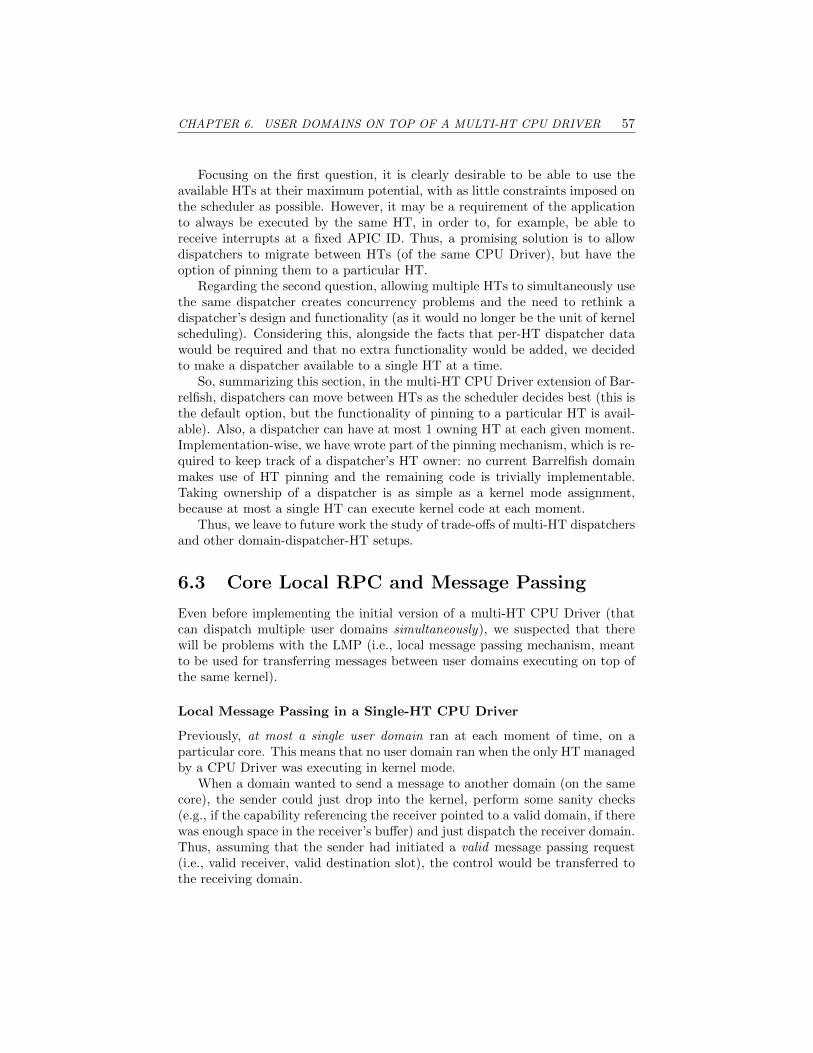
CHAPTER 6. USER DOMAINS ON TOP OF A MULTI-HT CPU DRIVER 57
Focusing on the first question, it is clearly desirable to be able to use theavailable HTs at their maximum potential, with as little constraints imposed onthe scheduler as possible. However, it may be a requirement of the applicationto always be executed by the same HT, in order to, for example, be able toreceive interrupts at a fixed APIC ID. Thus, a promising solution is to allowdispatchers to migrate between HTs (of the same CPU Driver), but have theoption of pinning them to a particular HT.
Regarding the second question, allowing multiple HTs to simultaneously usethe same dispatcher creates concurrency problems and the need to rethink adispatcher’s design and functionality (as it would no longer be the unit of kernelscheduling). Considering this, alongside the facts that per-HT dispatcher datawould be required and that no extra functionality would be added, we decidedto make a dispatcher available to a single HT at a time.
So, summarizing this section, in the multi-HT CPU Driver extension of Bar-relfish, dispatchers can move between HTs as the scheduler decides best (this isthe default option, but the functionality of pinning to a particular HT is avail-able). Also, a dispatcher can have at most 1 owning HT at each given moment.Implementation-wise, we have wrote part of the pinning mechanism, which is re-quired to keep track of a dispatcher’s HT owner: no current Barrelfish domainmakes use of HT pinning and the remaining code is trivially implementable.Taking ownership of a dispatcher is as simple as a kernel mode assignment,because at most a single HT can execute kernel code at each moment.
Thus, we leave to future work the study of trade-offs of multi-HT dispatchersand other domain-dispatcher-HT setups.
6.3 Core Local RPC and Message Passing
Even before implementing the initial version of a multi-HT CPU Driver (thatcan dispatch multiple user domains simultaneously), we suspected that therewill be problems with the LMP (i.e., local message passing mechanism, meantto be used for transferring messages between user domains executing on top ofthe same kernel).
Local Message Passing in a Single-HT CPU Driver
Previously, at most a single user domain ran at each moment of time, on aparticular core. This means that no user domain ran when the only HT managedby a CPU Driver was executing in kernel mode.
When a domain wanted to send a message to another domain (on the samecore), the sender could just drop into the kernel, perform some sanity checks(e.g., if the capability referencing the receiver pointed to a valid domain, if therewas enough space in the receiver’s buffer) and just dispatch the receiver domain.Thus, assuming that the sender had initiated a valid message passing request(i.e., valid receiver, valid destination slot), the control would be transferred tothe receiving domain.

CHAPTER 6. USER DOMAINS ON TOP OF A MULTI-HT CPU DRIVER 58
Note that this did not mean that the transfer would also be successful: thereceiver’s buffer could have been full or the receiver domain could have beendisabled (i.e., in a state in which the domain can not receive messages). In sucha case, an error would be reported to the sender, but the receiver domain wouldstill be the one dispatched upon kernel exit.
Adapting Local Message Passing to a Multi-HT CPU Driver
Having multiple HTs based on the same CPU Driver means that more than oneuser domain can execute code at a given time. For LRPC (i.e., local remoteprocedure call) & LMP, this translates into concern for a situation in which thereceiver domain is already executing (on another HT).
One solution to this problem, which is currently implemented, involves defin-ing a new error code for such a scenario: SYS ERR LMP TARGET RUNNING.This error code is returned to the sender domain in a manner similar the one inwhich the sender is informed that the receiver domain does not exist. Thus, theburden of retrying the message passing falls onto the sender domain. Depend-ing on the latency constraints for that particular inter-domain data transfer,the sender can loop and retry until the transfer emerges successfully, or it canyield the HT to another (user-space) thread or to another domain.
For non-urgent message passings, yielding is a good option. It can be im-proved by making the CPU Driver save the message in some buffer: the normalreceiver buffer can only be used if it is read-only for the receiver and if the saidbuffer is expected to be modified (by the message delivery mechanism) whilethe receiver is running.
If the CPU Driver has nowhere to store the message while the receiver isrunning, 2 other alternatives can be employed:
1. The sender’s HT can sleep (via monitor/mwait or hlt) until the receiver’sHT can release the receiver dispatcher. The advantage would be that otherHTs may use the sender HT’s hardware resources to accomplish usefultasks, better than the sender wasting them by looping on the failing sendoperation;
2. Ultimately, if latency is critical for the transfer in question, then the senderHT can send an IPI (i.e., inter-processor interrupt) to the receiver’s HT,making the receiver domain available for execution on the sender HT.
Having the previously mentioned alternatives in mind, we started exper-imenting with booting-up more than 2 HTs per CPU Driver. What we ob-served was that the system would stall and that domains would make no fur-ther progress when reaching 4 HTs. Listing 6.1 contains the output of the pscommand (note that ps does not display information about special Barrelfishdomains, such as init, monitor, mem server, ramfsd, skb).
The reason for this deadlock was the enormous rate (≈ 100%) of failing LMPtransfers, caused by the fact that the receiver was running on a different HTthan the sender. We solved the problem by implementing a mechanism which

CHAPTER 6. USER DOMAINS ON TOP OF A MULTI-HT CPU DRIVER 59
Listing 6.1: ps output on Barrelish’s BSP core.
1 > ps
2 DOMAINID STAT COMMAND
3 1 Z corectrl auto boot 2 -a loglevel =4
4 2 R pci auto
5 3 R serial
6 4 Z angler serial0.terminal xterm
7 5 R lrpc_bench server
8 6 R fish
puts APHTs (i.e., application hardware threads) to sleep. This mechanism isdetailed in Section 6.4.
Optimizing Local Message Passing to a Multi-HT CPU Driver
However, far more important was the observation that, in order to have a betterutilization of the processing power provided by HTs, we need to have a modelwhich can deliver LMP messages even when the target domain is executing.
As struct lmp endpoint kern (presented in Listing 6.2) is modified by boththe CPU Driver (when delivering an LMP message) and by the user-space do-main (when storing an LRPC payload or when updating the CNode reference forstoring capabilities transfered via LMP), we think the best solution would be tohave a separate buffer, meant to store LMP messages received while the targetdomain is running. The alternatives would be to either use atomic operationswhen modifying the buffer or to protect it with a lock. Since an LMP messagecan contain both normal payload of variable length (i.e., binary, opaque data,from the kernel’s viewpoint) and a capability, the type of needed atomic opera-tions is not actually available. Using a succession of simple atomic operationsis also not a good solution, because it could leave the buffer in an inconsistentstate at specific moments. As for the locking strategy, it creates the possibility ofuser-space blocking the kernel, by acquiring the lock and holding it indefinitely.
The instance of struct lmp endpoint kern meant to store the LMP messagesreceived while the target is running (on another HT) would, ideally, only bemodifiable by the CPU Driver. However, this is not a must, as a user domainmodifying said data would only hurt itself.
Another choice we have to make when working with 2 LMP buffers is theway in which the user domain will get access to both of them, in order to processthe messages. Rotating the 2 buffers was an idea, but it was discarded becauseit can lead to message reordering. Thus, we decided to go with the approachof copying messages from the kernel’s LMP buffer to the other buffer. This canbe done when the LMP channel’s dispatcher is not currently dispatched: forexample, when the domain is being evicted from the HT. If message latency isof concern, an IPI can be sent to the target HT, in order for it to do the message

CHAPTER 6. USER DOMAINS ON TOP OF A MULTI-HT CPU DRIVER 60
Listing 6.2: The C struct in which LMP messages are delivered.
1 /// Incoming LMP endpoint message buffer
2 struct lmp_endpoint_kern {
3 ///< CSpace address of CNode to receive caps
4 capaddr_t recv_cptr;
56 ///< Slot number in #recv_cptr
7 capaddr_t recv_slot;
89 ///< Valid bits in #recv_cptr
10 uint8_t recv_bits;
1112 ///< Position in buffer (words delivered by kernel)
13 uint32_t delivered;
1415 ///< Position in buffer (words consumed by user)
16 uint32_t consumed;
1718 ///< Buffer for async LMP messages
19 uintptr_t buf[];
20 };
copying.In this Section, a large number of solutions have been proposed, for a variety
of encountered problems. We highlighted the most important characteristics andcategorized them as pluses and minuses, but only implemented some of the ideas.The study of practical scenarios showcasing the advantages and disadvantagesof each approach is a good candidate for an extension to this Thesis.
6.4 HT Management
In the following paragraphs we will look into the logic that triggers the actionsof booting an HT, resuming an HT and putting it to sleep.
Starting with the first action, we would like to point out that there is anotable difference between the ways in which BSHTs and APHTs are addedto a Barrelfish instance. The former (i.e., BSHTs) are booted automaticallyupon discovery, by the kaluga domain, which issues the boot subcommand ofthe corectrl domain. Also, as the naming suggests (i.e., bootstrap hardwarethreads), each BSHT gets an uninitialized copy of the CPU Driver.
On the other hand, APHTs are currently booted up by executing the bootaphtsubcommand of corectrl manually: implementing the same auto-trigger as inthe case of BSHTs is a trivial task, but we wanted to make the exploration of

CHAPTER 6. USER DOMAINS ON TOP OF A MULTI-HT CPU DRIVER 61
different HT-to-CPU Driver assignments as straightforward as possible. Thefact that there is currently no piece of coded logic which boots APHTs meansthat kaluga does not need to be recompiled in order to explore different HTsetups: you just point an APHT towards an initialized CPU Driver by issuingcorectrl ’s bootapht subcommand in fish (i.e., the de-facto Barrelfish shell).
HTs go to sleep by executing the wait for interrupt function, which has beenadapted to release the kernel lock before running hlt. For BSHTs, this can onlyhappen when they have no domain to dispatch. Since the BSHT is the timekeeper of its CPU Driver, the APIC timer is never masked when a BSHT goesto sleep: the BSHT will be woken up, at latest, by the next timer interrupt.
For APHTs the same hold true, with the minor difference that their timersare masked when going to sleep. Additionally (from the case when no domain isavailable for dispatching), other situations can also make an APHT go to sleep:
• if the number of subsequent LMP messages that fail withSYS ERR LMP TARGET RUNNING (with not interleaved transfers thatend differently) exceeds a predefined limit (currently set to 1,000,000).This happens because we can not deliver an LMP message to a runningdomain;
• when the BSHT is forced to sleep because it has no domain to dispatch,it raises a condition in the CPU Driver which tells the first APHT tonotice the flag that it should (temporally) halt execution. The mentionedcondition is checked by APHTs during each timer interrupt handling. Wemade this decision because it is better to keep the BSHT awake wheneverpossible (as opposed to delegating the user tasks to an APHT), since italready wakes up at the end of each time slice.
As we already mentioned, a BSHT wakes from sleep as a result of an interruptand it sleeps with the timer unmasked in order to ensure that an interrupt occursat least once a time slice. This is mainly due to its important role in the CPUDriver, similar to that of a leader. On the other hand, APHTs are only useful ifthey can exploit the parallelism of user-space tasks, improving the throughputof the system. Thus, an event which can be taken into account when deciding towake up an APHT is that of a dispatcher being marked as runnable: this holdstrue because we are still in the context of single-threaded dispatchers, whichcan be executed by at most an HT at a time.
The logic leading to an HT entering parking state is depicted in Figures 6.1(for BSHTs) and 6.2 (for APHTs).

CHAPTER 6. USER DOMAINS ON TOP OF A MULTI-HT CPU DRIVER 62
Need to schedulea dispatcher
Can a dispatcherbe scheduled
on this BSHT?
Do dispatch
Is the flag (indi-cating an APHT
should sleep)raised?
Raise flag
Wait for interrupt
Yes No
Yes
No
Figure 6.1: Logic use by a BSHT when deciding if it should enter sleep. TheBSHT will be woken up, at latest, by the next timer interrupt.

CHAPTER 6. USER DOMAINS ON TOP OF A MULTI-HT CPU DRIVER 63
Need to schedulea dispatcher
Timer interrupt
Can a dispatcherbe scheduled
on this APHT?
Is the flag (indi-cating an APHT
should sleep)raised?
Do dispatch Handle interrupt
Clear flagWait for interrupt
YesNo
No Yes
Figure 6.2: Logic used by an APHT when deciding if it should enter sleep.The flag is raised by the BSHT (if it has no domain to dispatch) or by any HTnoticing a large number of failed LMPs, caused by the fact that the receiverdomain had been executing when message delivery was attempted.A sleeping APHT is woken up when a dispatcher becomes runnable.

CHAPTER 6. USER DOMAINS ON TOP OF A MULTI-HT CPU DRIVER 64
6.5 FPU Registers
In the single HT per CPU Driver scenario, considering that most user domainsdid not make use of the FPU (i.e., floating-point unit), a lazy approach wasemployed for dealing with FPU context switches. This involved maintaininga reference to the last domain that accessed the FPU and using a FPU trap(i.e., an interrupt that triggered when the trap was enabled and user-space codeaccessed the FPU) to lazily restore the FPU state.
Now, with domains being dispatched on multiple HTs, depending on thecurrent system load, a more eager approach for FPU context switching wasnecessary. Continuing to use a lazy solution would have made it complicatedand impractical for a domain to recover it FPU state, at need, from anotherHT.
For the purpose of maintaining the FPU state of a domain, we have imple-mented the fpu context switch function, which is responsible with:
• saving FPU registers when the user-domain executed by the HT changes;
• enabling the FPU trap when the HT’s domain changes and the new domainis enabled: user code, part of libbarrelfish, takes care of the FPU state whenthe domain had been in disabled state at the moment of its last eviction;
• restoring the FPU trap.
On the LRPC path, we are currently relying on the same C function (i.e.,fpu context switch). This aspect could be optimized in the future, by adaptingthe logic to the situation of an LRPC and implementing it directly in Assembly(as is most of the LRPC fast-path).
6.6 Benchmark
As a natural step following the addition of the multi-HT management function-ality to Barrelfish’s CPU Driver, we ran experiments aimed at determining theeffects of using multiple HTs on top of the same kernel. For this, we considered3 CPU Driver-HT configurations and 2 workloads.
The first configuration represents the baseline: a single HT is managed byeach CPU Driver. Since the machine on which we are executing the experimentsis vacherin (see hardware details in Section 4.4), there are 8 HTs available whenHyper-Threading Technology is enabled, meaning that there are 8 CPU Driversin the baseline configuration. This behavior is similar to that of the normalversion of Barrelfish.
The second and third CPU Driver-HT setups use 4 CPU Drivers each, withthe notable difference that the former halts half the available HTs (resulting in1 HT per CPU Driver), while the latter keeps all of the HTs awake (2 HTs perCPU Driver).

CHAPTER 6. USER DOMAINS ON TOP OF A MULTI-HT CPU DRIVER 65
The workloads that we employed are based on the Fhourstones bench-mark, which we detailed in Section 4.2 and utilized when conducting the HT-throughput-related experiments presented in Chapter 4.
Figure 6.3 depicts the data derived from our experiments. The plot on thetop (i.e., Figure 6.3a) used 8 single-threaded Fhourstones domains running inparallel, while the one at the bottom (i.e., Figure 6.3b) used only 4 Fhourstonesdomains.
These domains were uniformly distributed across CPU Drivers: this meansthat the domains did not migrate between CPU Drivers, but could do so insidethe group of HTs managed by the same kernel. Because of this migrationbetween HTs, we decided to use the CPU Driver’s time information (maintainedby the BSHT) in order to have a consistent view of time on all HTs sharing aCPU Driver. There is, however, a downside to this decision: the step withwhich the time information is updated can be as high as the time slice (in ourcase, 80 ms). Thankfully, the duration of the executed experiments was muchlarger (> 2.5 minutes), resulting in the effects of the degraded resolution beingnegligible.
Since the Fhourstones workloads were composed of domains which executedindependently, we used warm-up and cool-down phases for the experiments, inorder to maintain a constant system load during the measurement period ofeach domain. Also, each experiment was repeated 10 times.
Looking at the times measured when the 8 Fhourstones workload was used(i.e., Figure 6.3a), we see that it makes little difference if each HT has its ownCPU Driver or if there is only 1 CPU Driver per physical core (i.e., 2 tightlycoupled HTs). However, the same amount of work took a longer time when 4CPU Drivers were used and half of the HTs were put to sleep. The observationsare consistent with what we saw before: a single HT per physical core candeliver a higher throughput than each of the 2 HTs sharing a core, but the totalthroughput accomplished by the pair is even greater.
Moving on to the 4 Fhourstones workload (i.e., Figure 6.3b), we see that,again, the first and third configurations performed similarly. However, the sec-ond setup, in which a single HT per core was used, emerged as the best in thepresent situation: since the entire benchmark contained 4 independent threads(1 for each Fhourstones domain), the best utilization of the hardware resourceswas achieved when half of the HTs relinquished their share in order to increasethe throughput of the remaining 4 HTs. Simply putting it, there was not enoughparallelism in the workload for justifying the usage of more than 4 HTs.
Costs Associated with Parking and Resuming HTs
Based on what was discussed so far in the current Section, the main conclusionof the experiments depicted in Figure 6.3 is that the throughput of the systemcan be improved by tailoring the number of active HTs to a particular situation.In order for this adaptation procedure to be of practical relevance, it must havea very small overhead.
The normal version of Barrelfish, which uses single-HT CPU Drivers, is able

CHAPTER 6. USER DOMAINS ON TOP OF A MULTI-HT CPU DRIVER 66
8 CPU Drivers 4 CPU Drivers, 4/8 HTs halted 4 CPU Drivers, all HTs upexperiment
0
50
100
150
200
250
300
350ru
n tim
e (s
)APIC ID
01234567
(a) 8 Fhourstones workload.
8 CPU Drivers 4 CPU Drivers, 4/8 HTs halted 4 CPU Drivers, all HTs upexperiment
0
50
100
150
200
250
300
run
time
(s)
APIC ID01234567
(b) 4 Fhourstones workload.
Figure 6.3: Performance comparison between vacherin running Barrelfish withsingle-HT CPU Drivers and vacherin managed by multi-HT CPU Drivers. Theexperiment which utilized 8 CPU Drivers used the single-HT variant, while theother 2 experiments employed the multi-HT version. A black outline is used togroup HTs that were sharing the same CPU Driver and different shades of thesame color (i.e., dark vs light) are assigned to HTs sharing the same physicalCPU core. The run time and 95% confidence intervals are depicted for eachCPU Driver. The CIs are very tight relative to the execution time, which leadto them begin reduced to dots.

CHAPTER 6. USER DOMAINS ON TOP OF A MULTI-HT CPU DRIVER 67
to achieve the said effect by migrating KCBs (i.e., kernel control blocks) betweenCPU Drivers, as presented in [14]: before an HT is halted, its KCB is transferedto another HT, which alternates between the 2 kernel states. Notable operationsof this process and their associated costs are the following (the measurementswere taken on the same vacherin machine, identified as ”1×4 Haswell” in Table 2of [14]; Hyper-Threading Technology was disabled):
• sending an IPI to the core to be halted, the propagation of the IPI andexecuting the IPI handler on the receiving HT → 3,000 cycles;
• preparing a kernel on the HT meant to send the wake-up signal, up to thepoint when the IPI is sent to the sleeping HT → 26,000,000 cycles;
• initializing the CPU Driver on the woken-up HT → 2,000,000 cycles.
In order to simplify the comparison with the multi-HT CPU Driver Barrelfishvariant, we will consider:
• the cost of halting an HT, equivalent to the first of the previously men-tioned 3 operations → 3,000 cycles;
• the cost of resuming an HT, consisting of the last 2 operations →26,000,000 + 2,000,000 = 28,000,000 cycles.
For the multi-HT CPU Driver, we will use the data acquired by runningexperiments using the Normal Measurement Setup, as these results have beenreported in Subsection 4.1.1.:
• putting an HT to sleep implies that the HT in question does not own(i.e., have exclusive access to the state of) a dispatcher, so we considerthe cost associated with parking an HT to be 0.: we ignore the durationof evicting a dispatcher from the HT (i.e., save its state in the dispatchercontrol block).
Also, note that HTs determine they should sleep on their own or (in casethe BSHT wants to park an APHT) sending the sleep signal is as simpleas changing the value of a variable (i.e., raising the flag mentioned inSection 6.4);
• the cost of resuming an HT is comprised of sending the wake-up signal +the wake-up duration;
Table 6.1 summarizes the costs of parking and resuming HTs: it is easy toobserve that the options available when using multi-HT CPU Drivers are betterin terms of overhead.

CHAPTER 6. USER DOMAINS ON TOP OF A MULTI-HT CPU DRIVER 68
Table 6.1: The cost (in cycles) of parking and resuming HTs, depending on themechanism employed for carrying out these operations.“Move KCB” refers tothe setup presented in [14], while the columns under “Multi-HT CPU Driver”refer to using the mentioned synchronization operations, as they are presentedin Section 2.4.
OperationMechanism
Move KCBMulti-HT CPU Drivermonitor/mwait hlt
park HT 3,000 0 0resume HT 28× 106 1,160 2,140
Halted vs Not Started HT
In Section 4.2 we have made the empirical observation that there is no differencerelated to the processing power of an HT between the situation of disablingHyper-Threading and the case of parking all but 1 HT on each physical core.
Knowing this, it is highly probable that, on a 2-way SMT processor (suchas our vacherin machine), the performance of an HT is not affected differentlywhen its sibling HT is either halted or not started at all.
To assert this hypothesis, we compared the run times of both the 4 and 8Fhourstones workloads, when using 4 CPU Drivers and half the HTs (one oneach core) were either halted or not started.
The outcome of these experiments is presented in Figure 6.4 and is in linewith our assumption.
Conclusions of Benchmarking
As a conclusion to the observations presented in this Section, we think that themain benefit exhibited by the multi-HT CPU Driver is the added flexibility ofmanaging hardware threads, with very little overhead. We would also like topoint out the ability of Barrelfish using multi-HT CPU Drivers to be on par interms of performance with the single-HT CPU Driver version, and even surpassit by adapting to the characteristics of the employed workload.

CHAPTER 6. USER DOMAINS ON TOP OF A MULTI-HT CPU DRIVER 69
4 fhs., 4/8 HTs halted 4 fhs., 4/8 HTs not started 8 fhs., 4/8 HTs halted 8 fhs., 4/8 HTs not startedexperiment
0
50
100
150
200
250
300
350
run
time
(s)
APIC ID01234567
Figure 6.4: Comparison between the performance impact of halting an HTvs not starting it. The first 2 experiments employed a workload consisting of4 parallel Fhourstones benchmark runs (i.e., 1 on each HT), while the last 2doubled the workload (i.e., 2 Fhourstones on each HT). The representations aresimilar to those in Figure 6.3 and the conclusion is (as expected from previousobservations) that halting an HT is the same as not starting it.

CHAPTER 6. USER DOMAINS ON TOP OF A MULTI-HT CPU DRIVER 70
6.7 Optimizing the Scheduler
Based on the benchmarking-related discussion in Section 6.6, the low-overheadmechanisms available in the multi-HT CPU Driver which can be used to varythe number of awake HTs and, implicitly, which can influence hardware resourceallocation, have the potential of improving Barrelfish’s user task throughput.
It is, thus, important to detect the right moment for parking or resuming anHT. For this reason, we propose a scheduler optimization, meant to detect thecharacteristics of the executing workload and adapt the state of HTs accordingly.
Before we dive into the actual optimization, we would like to point out that,while the multi-HT CPU Driver implementation supports any number of HTsper CPU Driver, this optimization is aimed at 2-way SMT processors. Also, wefocus on improving the throughput of a group of batch tasks.
For each domain, we define the utilization (u, for short) as the ratio betweenthe used budget and the allocated budget, which, in the context of the RBEDscheduler [3] and for domain d, becomes:
ud =used budget
allocated buged=
execution time
worst case execution time
The decision of changing the state of an HT is made independently by eachCPU Driver’s scheduler as following:
• In the case 1 HT is active, the sibling HT is woken-up if:
min(∑
ud, 1)< min
∑ud≤66%
ud
+ 0.66× |{d|ud > 0.66}| , 1.33
The numbers in the above equation are based on our findings presented inSection 4.2: if the maximum throughput of a single HT per physical coreis normed to 1, then the maximum throughput of each HT (of a 2-waySMT core, both being active) is ≈ 0.66 (in total ≈ 1.33). This means thatwhen 1 HT is active per core, the maximum achievable throughput is 1,while both can deliver up to 1.33. Naturally, utilizations exceeding 0.66are capped at this value, since this is the upper limit of the throughputwhen both HTs are active.
• In the case both HTs are active, one of them is parked if (note that theexecution times for computing the utilizations are the ones measured onthe HT in question of being parked):∑
ud < 0.5
The idea behind this mathematical inequality is that, if an HT is notutilizing at least half of it processing power, then it should lend all itsresources to the other HT. Doing so increases the throughput of the activeHT with half of what it had when both HTs were awake.

CHAPTER 6. USER DOMAINS ON TOP OF A MULTI-HT CPU DRIVER 71
While this idea of optimizing the scheduler is intuitively sound, it still needsfurther refinement. For example, an important aspect is related to the way thesechanges will influence RBED’s invariants: best effort tasks can probably copepretty easily with the modifications, but this may not be the case with soft andhard real-time tasks.
Also, there is the question of how will the proposed mechanism tasked withmanaging hardware threads interact with parallel programs: an OpenMP-basedprogram can spawn a variable number of worker threads, but how does the op-timal number of said workers depend on the processing power of the underlyingHTs?
Unfortunately, there was not enough time during this Thesis in order tofurther tackle the challenge of optimizing HT management. Thus, this mightbe a good candidate for future improvements to the multi-HT CPU Driver.

Chapter 7
Conclusions and FutureWork
Conclusions
In the final paragraphs of this Thesis, we would like to take a step back and givea clear overview of what we wanted to achieve and what are the contributionsgenerated by our work.
We started off from the idea that SMT lanes should not be treated in thesame way as normal CPU cores, since they share much more hardware resources(e.g, execution units and caches) when compared to different cores (which aremore independent). This idea was based on the previous work carried out by XiYang et al. regarding the Elfen Scheduler [13], which we wanted to reproduceand extend in the context of the Barrelfish Operating System.
The initial plan focused on experimenting with a number of models whichthe OS could use to manage HTs, most of these models being aimed at providingfast context switching (between user and kernel spaces, or from one user domainto another). Thus, the first step that we took was to determine the cost ofsynchronizing HTs, which we found to be at least 1250 cycles on an Intel HaswellCPU, with 2-way SMT via Hyper-Threading Technology. This value representsthe time it takes a sleeping HT to resume execution and is on par with what theElfen Scheduler paper [13] states. However, because the duration of performinga virtual address space switch (683 cycles, with TLB tagging) was about half ofthe HT’s wake-up duration, we decided, for practical reasons, that most of ourinitially proposed models do not make sense.
Moving forward, we considered worth pursuing the idea of having multipleHTs sharing the same single-lock guarded CPU Driver, with each SMT lane in-dependently dispatching user-space tasks. Thus, we made the necessary changesto the CPU Driver and modified the kernel’s scheduling and dispatcher man-agement logic. The result was a CPU Driver which could accommodate a groupof HTs, let each of these HTs execute user-tasks in parallel and reconcile themat need (for example, when LMP messages could not be delivered because the
72

CHAPTER 7. CONCLUSIONS AND FUTURE WORK 73
receiver domain was executing in parallel with the sender).We measured the impact of our changes by running a series of experiments
and comparing the performance against that of Barrelfish powered by the single-HT version of the CPU Driver. In the end, the main advantage of the multi-HTCPU Driver turned out to be its ability to vary the number of active HTs, withvery little overhead when compared to the previously available mechanisms.
Future Work
As can be observed from the path that we took during this Thesis, our primaryobjective was to explore the uncharted territory of using the same CPU Driverto manage multiple HTs. This means that we focused more on weighting thetrade-offs between different ideas and were able to allocate less time to refininga specific one.
In the future, we hope that our proposed model will be expanded uponand that certain aspects of it will be optimized. Improving the scheduler andadapting it to better leverage the new context is an interesting and vast topicwhich includes: determining the best allocation of user tasks to each HT, ex-ploring the possibilities generated by multi-HT enabled dispatchers, detectingwhich HT configuration is best for a given scenario. Related to this topic, amore focused subject is the refinement of our half-backed optimization proposalfor the RBED Scheduler, by adapting the said algorithm in order to preserve(part of) the invariants. Also, the cooperation between the CPU Driver’s HTmanagement logic and parallel user tasks can be beneficial for the throughputof the system, by giving both pieces of logic a consistent view of the availableHT characteristics and configurations.
An important and intensively used Barrelfish mechanism, which is in needof fundamental modifications, is LMP. Assumptions that were valid in a single-HT CPU Driver are no longer true when the CPU Driver manages multipleHTs. The changes that we had to make in order to ensure that messages canbe successfully transfered between domains (executing on top of the same CPUDriver) have a negative impact on performance. A more fundamental redesign ofthe message passing logic, by allowing, for example, data transfers to be carriedout to a running domain, has the potential of greatly improving our work.
Overall, we feel that this Thesis and the associated implementation helppave the way to further Operating System Research.

Bibliography
[1] Team Barrelfish. Barrelfish Architecture Overview. Version 2.0. http://www.barrelfish.org/publications/TN-000-Overview.pdf. 2013.
[2] Andrew Baumann. Inter-dispatcher communication in Barrelfish. 2011.url: http://www.barrelfish.org/publications/TN-011-IDC.pdf.
[3] Scott A Brandt et al. “Dynamic integrated scheduling of hard real-time,soft real-time, and non-real-time processes”. In: Real-Time Systems Sym-posium, 2003. RTSS 2003. 24th IEEE. IEEE. 2003, pp. 396–407.
[4] Intel R© 64 and IA-32 Architectures Optimization Reference Manual. Sec-tion 2.6 Intel R© Hyper-Threading Technology. 2016.
[5] Intel R© 64 and IA-32 Architectures Optimization Reference Manual. Sec-tion 8.4 Thread Synchronization. 2016.
[6] Intel R© 64 and IA-32 Architectures Software Developers Manual. Section17.15.1 Invariant TSC. 2016.
[7] Sean Peters et al. “For a microkernel, a big lock is fine”. In: Proceedingsof the 6th Asia-Pacific Workshop on Systems. ACM. 2015, p. 3.
[8] Phoronix Test Suite - Linux Testing and Benchmarking Platform, Au-tomated Testing, Open-Source Benchmarking. url: http://phoronix-test-suite.com/.
[9] Simultaneous multithreading. url: https://en.wikipedia.org/wiki/Simultaneous_multithreading.
[10] Livio Soares and Michael Stumm. “FlexSC: Flexible system call schedul-ing with exception-less system calls”. In: Proceedings of the 9th USENIXconference on Operating systems design and implementation. USENIX As-sociation. 2010, pp. 33–46.
[11] The Barrelfish Operating System. url: http://www.barrelfish.org.
[12] The Fhourstones Benchmark. url: http : / / tromp . github . io / c4 /
fhour.html.
[13] Xi Yang, Stephen M Blackburn, and Kathryn S McKinley. “Elfen schedul-ing: fine-grain principled borrowing from latency-critical workloads usingsimultaneous multithreading”. In: 2016 USENIX Annual Technical Con-ference (USENIX ATC 16). USENIX Association. 2016, pp. 309–322.
74

BIBLIOGRAPHY 75
[14] Gerd Zellweger et al. “Decoupling Cores, Kernels, and Operating Sys-tems.” In: OSDI. Vol. 14. 2014, pp. 17–31.

Declaration of originality The signed declaration of originality is a component of every semester paper, Bachelor’s thesis, Master’s thesis and any other degree paper undertaken during the course of studies, including the respective electronic versions. Lecturers may also require a declaration of originality for other written papers compiled for their courses. __________________________________________________________________________ I hereby confirm that I am the sole author of the written work here enclosed and that I have compiled it in my own words. Parts excepted are corrections of form and content by the supervisor. Title of work (in block letters):
Authored by (in block letters): For papers written by groups the names of all authors are required. Name(s): First name(s):
With my signature I confirm that
− I have committed none of the forms of plagiarism described in the ‘Citation etiquette’ information sheet.
− I have documented all methods, data and processes truthfully. − I have not manipulated any data. − I have mentioned all persons who were significant facilitators of the work.
I am aware that the work may be screened electronically for plagiarism. Place, date Signature(s)
For papers written by groups the names of all authors are
required. Their signatures collectively guarantee the entire content of the written paper.
EXPLICIT OS SUPPORT FOR HARDWARE THREADS
POENARU ANDREI
Zürich, 22.03.2017