Master Vol 1
668
CHRYSLER / PLYMOUTH / DODGE / DODGE TRUCK / JEEP DaimlerChrysler Corporation Technical Service Bulletins This book is part of a two-volume set. One volume, Publication Number 81-170-00001, covers service bulletins. Technical Service Bulletins are published to update and inform the service trades of engineering changes, production changes, and revised or new repair and diagnosis techniques. The other volume, 81-170- 00002, contains bulletins that supplement and revise technical information previously published in service manuals. Contents—Bulletins are grouped by subject and can be quickly located by using the tab index and the matching tab in the book. A master index is included to provide quick reference for all bulletins published in 2000. Each group has an index which identifies the bulletin Subject, Models and T.S.B. Number. Those bulletins listed were the only ones published. Part Numbers—Part numbers found throughout these bulletins are subject to change. Consult your current catalogs to confirm part numbers and availability. Policy—These bulletins are supplied as technical in- formation only. They are not an authorization for re- pairs. Reprinting of this information in whole or part is not authorized unless approved. DaimlerChrysler Corporation reserves the right to make changes in design or to make additions or improvements in its product without imposing any obligations upon itself to install them on its products previously manufactured. Litho in U.S.A. R DaimlerChrysler Corporation 2001 TAB INDEX Master Index 2 Front Suspension 3 Rear Axle 5 Brakes Brakes 7 Cooling 8 Electrical 9 Engine 11 Exhaust 13 Frame & Bumpers 14 Fuel 18 Driveability 19 Steering 21 Transmission 22 Wheels 23 Body 24 Heating & A/C
Transcript of Master Vol 1

CHRYSLER / PLYMOUTH / DODGE / DODGE TRUCK / JEEP
DaimlerChrysler Corporation
Technical Service Bulletins
This book is part of a two-volume set. One volume,Publication Number 81-170-00001, covers servicebulletins. Technical Service Bulletins are published toupdate and inform the service trades of engineeringchanges, production changes, and revised or new repairand diagnosis techniques. The other volume, 81-170-00002, contains bulletins that supplement and revisetechnical information previously published in servicemanuals.
Contents— Bulletins are grouped by subject and canbe quickly located by using the tab index and thematching tab in the book. A master index is included toprovide quick reference for all bulletins published in2000.
Each group has an index which identifies the bulletinSubject, Models and T.S.B. Number. Those bulletinslisted were the only ones published.
Part Numbers— Part numbers found throughout thesebulletins are subject to change. Consult your currentcatalogs to confirm part numbers and availability.
Policy— These bulletins are supplied as technical in-formation only. They are not an authorization for re-pairs. Reprinting of this information in whole or part isnot authorized unless approved.
DaimlerChrysler Corporation reserves the right tomake changes in design or to make additions orimprovements in its product without imposing anyobligations upon itself to install them on its productspreviously manufactured.
Litho in U.S.A. R DaimlerChrysler Corporation 2001
TAB INDEX
Master Index
2 Front Suspension
3 Rear Axle
5 BrakesBrakes
7 Cooling
8 Electrical
9 Engine
11 Exhaust
13 Frame & Bumpers
14 Fuel
18 Driveability
19 Steering
21 Transmission
22 Wheels
23 Body
24 Heating & A/C

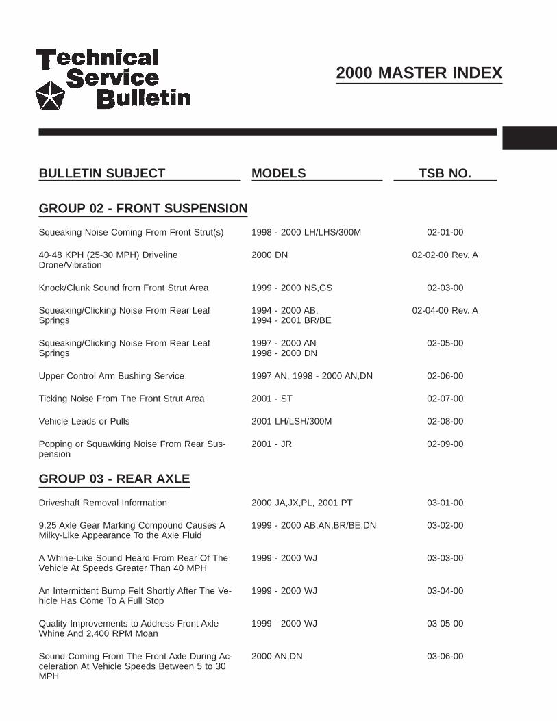
2000 MASTER INDEX
BULLETIN SUBJECT MODELS TSB NO.
GROUP 02 - FRONT SUSPENSION
Squeaking Noise Coming From Front Strut(s) 1998 - 2000 LH/LHS/300M 02-01-00
40-48 KPH (25-30 MPH) DrivelineDrone/Vibration
2000 DN 02-02-00 Rev. A
Knock/Clunk Sound from Front Strut Area 1999 - 2000 NS,GS 02-03-00
Squeaking/Clicking Noise From Rear LeafSprings
1994 - 2000 AB,1994 - 2001 BR/BE
02-04-00 Rev. A
Squeaking/Clicking Noise From Rear LeafSprings
1997 - 2000 AN1998 - 2000 DN
02-05-00
Upper Control Arm Bushing Service 1997 AN, 1998 - 2000 AN,DN 02-06-00
Ticking Noise From The Front Strut Area 2001 - ST 02-07-00
Vehicle Leads or Pulls 2001 LH/LSH/300M 02-08-00
Popping or Squawking Noise From Rear Sus-pension
2001 - JR 02-09-00
GROUP 03 - REAR AXLE
Driveshaft Removal Information 2000 JA,JX,PL, 2001 PT 03-01-00
9.25 Axle Gear Marking Compound Causes AMilky-Like Appearance To the Axle Fluid
1999 - 2000 AB,AN,BR/BE,DN 03-02-00
A Whine-Like Sound Heard From Rear Of TheVehicle At Speeds Greater Than 40 MPH
1999 - 2000 WJ 03-03-00
An Intermittent Bump Felt Shortly After The Ve-hicle Has Come To A Full Stop
1999 - 2000 WJ 03-04-00
Quality Improvements to Address Front AxleWhine And 2,400 RPM Moan
1999 - 2000 WJ 03-05-00
Sound Coming From The Front Axle During Ac-celeration At Vehicle Speeds Between 5 to 30MPH
2000 AN,DN 03-06-00

BULLETIN SUBJECT MODELS TSB NO.
Noise/Vibration In Drivetrain And/Or Front Pro-peller Shaft Constant Velocity Boot Integrity
2001 - AN,DN 03-07-00
RTV Use On Corporate Axle 1998 - 2001 AB,AN,BR/BE,DN,XJ
03-08-00
GROUP 05 - BRAKES
Brake Roughness Or Pedal Pulsation When TheBrakes Are Applied
1999 - 2000 WJ 05-01-00 Rev. A
Revised Parking Brake Equalizer Assembly Re-moval Procedures
2001 PT 05-02-00
Proportioning Valve Brake Pressure Adapter ToolRevision
1995 - 1999 PL 05-03-00
High Pitched Squeal From Rear Brakes 2000 - BR/BE 05-04-00
Rear Brake Clunk Or Thump When Brakes AreApplied
1997 - 1998 XJ 05-05-00
Front Brake Caliper Anti-Rattle Clip Retainer Ser-vice Procedures
2000 - 2001 BR/BE 05-06-00
Rear Disc Brake Squeal 2001 RS 05-07-00
GROUP 07 - COOLING
Cold Off-Idle Engine 9Growl9 Sound 1998 - 2000 LH/LHS/300M 07-01-00
Engine Cooling System Fill Procedure 1993 - 2001 LH 07-02-00
The Check Gauges Light Indicating A CoolantTemperature Concern May Illuminate After Ex-tended idling In Drive During Ambient Tempera-tures Over 35 deg. C (95 Deg. F).
2000 - TJ 07-03-00
Transaxle Cooler Line Splice Kit 2001 - JR,PL,PT,RG,RS 07-04-00
GROUP 08 - ELECTRICAL
No Start (Engine Will Not Crank) Due To A BlownStarter Relay Circuit Fuse
2000 AB, 2000 - 2001 AB,BR/BE
08-01-00 Rev. A
Headlamp Welt Service 1998 - 2000 LH/LHS/300M 08-02-00
Erratic Operation Of The Power Door Locks, Re-mote Keyless Entry System, Power Windows OrPower Mirrors
1999 WJ 08-03-00

BULLETIN SUBJECT MODELS TSB NO.
Light Bulb Applications And Replacement Infor-mation
2001 PT 08-04-00
Intermittent Operation Of The Instrument Cluster 1999 - AB,AN,BR/BE,DN 08-05-00
Wire Splice Repairs 1988 - BB 1989 - AA,AB,AC,AD,AG, AH,AJ,AK,AL,AM,AN,AP,AS,B2,B7,MJ,XJ,YJ1990 - AA,AB,AC,AD,AG,AJ,AK, AL,AN,AP,AS,AY,BB,BD,B2,B7,MJ1991 - AA,AB,AC,AD,AG,AJ,AN,AP,AS,AY,BB,BD,B2,B7,MJ,XJ,YJ1992 - AA,AB,AC,AD,AG,AJ,AN,AP,AS,AY,BB,BD,B2,B3,B7,B8,ES,MJ,XJ,YJ1993 - AA,AB,AC,AD,AG,AJ,AN,AP,AS,AY,BD,B3,B7,B8,B9,ES,LH,XJ,YJ,ZJ1994 - AA,AB,AG,AJ,AN,AP,AS,BD,BR/BE,B3,B7,B8,B9,ES,LH,XJ,YJ,ZJ F1995 - AA,AB,AJ,AN,AS,BR/BE,B3,B7,B8,ES,FJ,JA,LH,PL,XJ,YJ,ZJ1996 - AB,AN,BR/BE,FJ,GS,JA,JX,LH,NS,PL,SR,XJ,ZG,ZJ1997 - AB,AN,BR/BE,FJ,GS,JA,JX,LH,NS,PL, ,PR,SR,TJ,XJ,ZG,ZJ1998 - AB,AN,BR/BE,DN,FJ,GS,JA,JX,LH,NS,PL,PR,SR,TJ,XJ,ZG,ZJ1999 - AB,AN,BR/BE,DN,FJ,GS,JA,JX,LH,NS,PL,PR,SR,TJ,WJ,XJ2000 - AB,AN,BR/BE,DN,FJ,GS,JA,JX,LH,NS,PL,PR,SR,TJ,WJ,XJ,2001 AB,AN,BR/BE
08-06-00 Rev. A
Erroneous MIL Due To DTC P0443 (Purge Ckt)And/Or A Possible Key-Off Battery Draw
1999 DN 08-07-00
Inoperative Or Intermittent Remote Keyless Entry(RKE) Transmitter
1998 - 2000 LH1999 - 2000 AN,DN,BR/BE,XJ,WJ,AB 2000 - PL
08-08-00
Headlamp Service Change 2000 Concorde/LHS 300M 08-09-00
Dead Battery And/Or Ignition Operated ElectricalAccessories Function With Ignition Off
2000 - AN, 1998 - 2000 DN 08-10-00
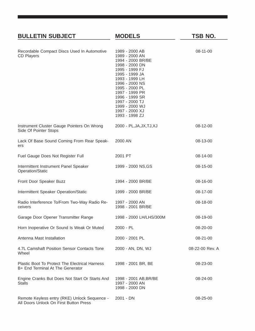
BULLETIN SUBJECT MODELS TSB NO.
Recordable Compact Discs Used In AutomotiveCD Players
1989 - 2000 AB1989 - 2000 AN1994 - 2000 BR/BE1998 - 2000 DN1995 - 1999 FJ1995 - 1999 JA1993 - 1999 LH1996 - 2000 NS1995 - 2000 PL1997 - 1999 PR1996 - 1999 SR1997 - 2000 TJ1999 - 2000 WJ1997 - 2000 XJ1993 - 1998 ZJ
08-11-00
Instrument Cluster Gauge Pointers On WrongSide Of Pointer Stops
2000 - PL,JA,JX,TJ,XJ 08-12-00
Lack Of Base Sound Coming From Rear Speak-ers
2000 AN 08-13-00
Fuel Gauge Does Not Register Full 2001 PT 08-14-00
Intermittent Instrument Panel SpeakerOperation/Static
1999 - 2000 NS,GS 08-15-00
Front Door Speaker Buzz 1994 - 2000 BR/BE 08-16-00
Intermittent Speaker Operation/Static 1999 - 2000 BR/BE 08-17-00
Radio Interference To/From Two-Way Radio Re-ceivers
1997 - 2000 AN1998 - 2001 BR/BE
08-18-00
Garage Door Opener Transmitter Range 1998 - 2000 LH/LHS/300M 08-19-00
Horn Inoperative Or Sound Is Weak Or Muted 2000 - PL 08-20-00
Antenna Mast Installation 2000 - 2001 PL 08-21-00
4.7L Camshaft Position Sensor Contacts ToneWheel
2000 - AN, DN, WJ 08-22-00 Rev. A
Plastic Boot To Protect The Electrical HarnessB+ End Terminal At The Generator
1998 - 2001 BR, BE 08-23-00
Engine Cranks But Does Not Start Or Starts AndStalls
1998 - 2001 AB,BR/BE1997 - 2000 AN1998 - 2000 DN
08-24-00
Remote Keyless entry (RKE) Unlock Sequence -All Doors Unlock On First Button Press
2001 - DN 08-25-00

BULLETIN SUBJECT MODELS TSB NO.
Central Timer Module Electrically 9Locks-Up9 2000 - AB,AN,BR/BE,DN2001 - AB,BR/BE
08-26-00
Non-Deployed Airbag Handling Procedures 1990 - 1995 AA 1995 - 2001 AB1990 - 1993 AC1988 - 1993 AG1988 - 1995 AJ 1990 AL1988 - 1989 AM1994 - 2001 AN1990 - 1994 AP1990 - 1991 AQ1991 - 1995 AS1990 - 1993 AY1994 - 2001 BR1995 - 1996 B71998 - 2001 DN1995 - 2000 FJ,JA2001 - JR 1996 - 2000 JX1993 - 2001 LH1996 - 2000 NS1995 - 2001 PL1997 - 2001 PR2001 PT,RS1996 - 2001 SR2001 ST 1997 - 2001 TJ1999 - 2001 WJ1995 - 2001 XJ 1993 - 1998 ZJ
08-27-00
Inoperative speedometer or Tachometer Due toGauge Needle Wrap Around
1999 - 2000 WJ 08-28-00
Minivan Electrical System Information 2001 - RS,RG 08-29-00
Instrument Cluster Illumination InoperativeAnd/Or Antilock Brake System Lamp Illuminated
2001 RS,RG 08-30-00
Window Sticks In the Up Position 1998 - 2001 LH/LHS/300M 08-31-00
Service 4WD Lamp Illuminated On 4X2 Vehicles 2001 - AN,DN 08-32-00 Rev. A
9Cold CD9 Fault Code in Sales CodeRBP/RAD/RBT/RBY - CD Players
2001 - AN,DN,JR,LH-,PL,PT,WJ,WG
08-33-00
PCE Relay Remover/Installation Tool 2001 - PT 08-34-00
Vehicle Surge While Speed Control Is Engaged 2001 - AN,DN 08-35-00
Circuits Effected By Ignition Off Draw (IOD) Fuse 2001 - AB,AN/AN84,BR/BE,DN,JR/JR27,LH,PL/P2,PT,PR,RG,RS,SR,ST,TJ,WG,WJ,XJ
08-36-00
Driver’s Air Bag Service 2001 - PT 08-37-00
Safety Systems - Vehicle Modifications/Repair 2001 - AB,AN,BR/BE,DN,JR,LH,PL,PR,PT,RS,RG,SR,ST,TJ,WJ,WG,XJ
08-38-00

BULLETIN SUBJECT MODELS TSB NO.
Sentry Key - Key Immobilizer Security System 2001 - ST 08-39-00
Motor Replacement - Power Seat Slide Adjuster 1995 - 2000 FJ 08-40-00
Intermittent Locking/Unlocking Of Door WithoutActivating The Power Door Lock Switch
2000 - 2001 AB,AN,BR/BE,DN 08-41-00
Remote Keyless Entry (RKE) Transmitter Pro-gramming
2001 - AN,DN,JR,LH,LHS/300M,RS
08-42-00
GROUP 9 - ENGINE
Normal Accumulation Of A Foamy Oil EmulsionIn The 4.7L Engine Oil Fill Housing
1999 - 2000 WJ, 2000 - AN,DN 09-01-00 Rev. A
A Heavy Oil Or Fuel-Like Odor Coming FromThe Diesel Engine Compartment
1999 - 2000 BR/BE 09-02-00
Engine Oil Seepage Past The Oil Fill Cap On5.9L-24V Diesel Engine
2000 BR/BE
Replacement Engine Break-In Procedure 1992 - 2000 SR 09-04-00
Spark Knock And engine Oil Consumption DueTo Intake Manifold Pan Gasket Oil Leak
1994 - 1999 AB, AN,BR/BE,1994 - 1998 ZJ 1996 - 1998 ZG
09-05-00
Changes To Timing Belt Tensioner Components 1999 - 2000 GS,JA,JX,PL 09-06-00
Air Filter Service 1994 - 2001 BR/BE 09-07-00
Front Cam Seal Retention 1997 - 1998 - GS1995 - 1998 - JA1994 - 1998 - PL
09-08-00
GROUP 11 - EXHAUST
1700 - 2400 RPM Exhaust Drone 2000 XJ 11-01-00 Rev. A
GROUP 13 - FRAME & BUMPERS
Snapping/Popping/Clunking Noise Heard DuringBraking Or While Driving Over Bumps
2000 AN,DN 13-01-00 Rev. B
Transmission Crossmember Service 2000 - 2001 AN,DN 13-02-00
GROUP 14 - FUEL
Thump/Bump Sound Heard 1-3 Seconds AfterThe Vehicle Comes To A Stop
2000 BR/BE 14-01-00
Crack In Diesel Fuel Filter Housing CoverCaused By An Improper Servicing Procedure
2000 - 2001 BR/BE 14-02-00

BULLETIN SUBJECT MODELS TSB NO.
Maintenance To The Water-In-Fuel SensorProbes Due To Possible Fuel Contamination
1998 - 2001 BR/BE 14-03-00
Vehicle Is Hard Or Slow To Start 2001 PT 14-04-00
Premium Fuel (91 Octane) Use RequirementWith Durango R/T 5.9L Engine
2000 DN 14-05-00
Longer Than Normal Engine Crank Time Prior ToEngine Start
1999 - 2000 WJ 14-06-00 Rev. A
GROUP 18 - DRIVEABILITY
Misdiagnosed Leak Detection Pump SystemsWith DTC P1494,P0442,P0455, or P0456
1997 - 2000 AB,AN,BR/BE,DN,FJ,JA,JX,LH,NS,PL,PR,SR,TJ,WJ,XJ,1997 - 1998 ZJ
18-01-00
PCV Valve Freeze Up 1996 - 2000 NS 18-02-00
EGR Monitor Diagnostic Test Difficult to Com-plete Or 9NOT READY9 At High Altitudes (Above4000 Feet)
1999 - 2000 NS 18-03-00
Erroneous MIL With P0441 - EVAP PURGEFLOW MONITOR FAILURE
2001 - PT 18-04-00
1998 Model Year Engine Spark Knock 1998 - AB,AN,BR/BE,DN 18-05-00 Rev. G
1999 Model Year Engine Spark Knock 1999 - AB,AN,BR/BE,DN 18-06-00 Rev. C
Erroneous MIL With P0645, P1282, P1489,P1490, Or P1495 After Shutting Off IgnitionWhile In Gear With Brake Pedal Depressed
2001 PT 18-07-00
Erroneous MIL Illumination Due To DTC P0107 -Map Sensor Voltage Too Low
1996 - 1998 AB,AN,BR/BE,DN,XJ, 1997 - 1998 TJ
18-08-00
2000 Model Year Engine Spark Knock 2000 - AB,AN,BR/BE 18-09-00 Rev. D
No Response From TCM When Using Some Ge-neric Scan Tools
2000 - GS,JA,JX,NS,PR 18-10-00
Low Voltage Clutch Protection - Added DTC -P1714 Low Battery Voltage
1999 - FJ,GS,JA,JX,LH,LHS,300M,NS,PR
18-11-00
Revised MIL Feature For Customer OBDII I/MReadiness
2001 - JR,PL,PT,RG,RS 18-12-00
Idle Fluctuation And/Or Tip In Hesitation At LowSpeed
2000 - LH 18-13-00

BULLETIN SUBJECT MODELS TSB NO.
4 To 3 Harsh Downshift In The 25 TO 40 MPHRange
2000 LH/LHS/300M 18-14-00
Driveability Enhancements With Winter Fuel UseAnd For Hard Not Engine Restarts
1999 - 2001 BR/BE 18-15-00 Rev. A
Poor A/C Or Engine Performance 2001 PL 18-16-00
Torque Converter Clutch Control/Kickdown ShiftQuality Improvements
1999 - LH,LHS/300M 18-17-00
Driveability Improvements/System Enhancements 2001 PT 18-18-00
Driveability Improvements 2000 - PL 18-19-00
Tip In Hesitation Caused By High DI Fuel 2001 - PL 18-20-00
Intermittent VTA, Overhead Temperature DisplaySlow To Update, Poor AC Performance AfterStart UP
1998 - 1999 LH,LHS/300M 18-21-00
2001 M.Y. Engine Spark Knock 2001 - BR/BE,DN 18-22-00
4.7L Engine Performance Enhancements 1999 - 2000 WJ 200 - DN, AN 18-23-00 Rev. A
Low Engine Power When The Automatic Trans-mission Is In Overdrive
2001 - BR/BE 18-24-00
GROUP 19 - STEERING
Steering Gear/Front Suspension Rattle 1998 - 2000 LH,LHS/300M 19-01-00
Ignition Lock Cylinder Service 2000 - PL,JA,JX,XJ,TJ2001 - PT
19-02-00 Rev. A
Loose Steering 1993 - 2000 LH 19-03-00 Rev. B
Squeaking/Creaking Sound In Steering ColumnWhile Turning
1994 - 2000 BR/BE,1997 - 2000 AN,1998 -2000 (R1)
19-04-00
Low Speed Power Steering Moan 2000 - 2001 PL 19-05-00
Steering Gear Honk On Turns 1999 - 2000 WJ 19-06-00
Steering Wander Diagnosis 1998 - 2001 AB 19-07-00
High Pitched Whistle Sound Heard While Driving 2001 - BR/BE 19-08-00
Popping Sensation/Sound In Steering ColumnWhile Turning
2001 - NA,DN,R1 19-09-00

BULLETIN SUBJECT MODELS TSB NO.
GROUP 21 - TRANSMISSION
Intermittent Harsh Engagement Into ReverseGear On Certain RE Model Transmissions
1999 - 2000 AN,BR/BE,WJ,2000 - AB,DN
21-01-00
47RE Transmission - Delayed Upshift Or NoTCC Engagement Between 30 and 50 MPH
1999 - 2000 BR/BE 21-02-00
NV-242 And NV-242HD Transfer Case Oil Seep-age From The Sector Shaft Oil Seal
1998 - AN,DN 1999 - WJ 21-03-00
Erroneous MIL Illumination For P1763 - Trans.Governor Pressure Sensor Volts Too High
1996 - 1999 AB,AN,BR/BE,XJ,1997 - 1999 TJ, 1998 - 1999 -DN
21-04-00
All Wheel Drive Power Transfer Unit Failure 1996 - 2000 NS,GS 2001RS,RG
21-05-00
Electronic Shift Transfer Case Features And Op-erating Characteristics
2001 - AN,DN 21-06-00
31th Delayed Engagement 2000 - NS,PL,P2 21-07-00
47RE Delayed TCC Lock-Up and/or MIL P1740 +TCC or O/D Solenoid Performance
1999 - 2000 BR/BE 21-08-00
45RFE Transmission Quality Enhancements ForThe 1-2, 2-3, and 4-3 Shifts
2000 AN,DN,WJ, 1999 - WJ 21-09-00
47RE Harsh Engagement When The TorqueConverter Clutch Is Applied
2000 - 2001 BR/BE 21-10-00
46RE Transmission MIL Due To DTC P1740 -TCC or OD Solenoid Performance
2000 - 2001 AB,AN,BR/BE,DN 21-11-00
Tapping/Knocking Sound During Idle 2000 - 2001 BR/BE 21-12-00
GROUP 22 - WHEELS
Spare Tire Winches 1999 - 2000 NS,GS 22-01-00
Wheel Cover Rattle - 149 Steel Wheels 2000 PL 22-02-00
GROUP 23 - BODY
Convertible Top Damage 1997 - 2000 PR 23-01-00
Internal Emergency Trunk Release 1993 - 2000 LH, 1995 - 2000JA,PL 1996 - 2000 JX
23-02-00
Vehicle Identification Number (VIN) Plate Relo-cated
2000 - AN,BR/BE,DN 23-03-00

BULLETIN SUBJECT MODELS TSB NO.
Door Trim Panel Cracking At Lower AttachingBosses
1998 - 1999 LH/LHS/300M 23-04-00
Driver’s Seat Back Cover Torn Or Door TrimPanel Damaged
2000 JX 23-05-00
Water Leak From Top Edge Of Right Or LeftFront Door
2000 PL 23-06-00
Wind Noise 1998 - 2000 LH,LHS/300M 23-07-00
Child Seat Tether Anchors 1988 - BB 1989 - AA,AB,AC,A-G,AH,AJ,AK,AL,AM,AN,AP,AS,BB,B2,B5,B7,XJ,1990 - AA,AB,AC,AG,AJ,AK,AL,AN,AP,AS,AY,BB,BD,B2,B7,XJ1991 - AA,AB,AC,AG,AJ,AN,AP,AS,AY,BB,BD,B2,B7,XJ1992 - AA,AB,AC,AG,AJ,AN,AP,AS,AY,BB,BD,B2,B3,B7,B8,XJ1993 - AA,AB,AC,AG,AJ,AN,AP,AS,AY,BD,B3,B7,B8,B9,LH,XJ,ZJ1994 - AA,AB,AG,AP,AS,BD,BR/BE,B3,B7,B8,B9,LH,XJ,ZJ1995 - AA,AB,AN,AS,BR/BE,B3,B7,B8,FJ,JA,LH,PL,XJ,ZJ1996 - AB,AN,BR/BE,FJ,JA,LH,NS,PL,SR,XJ,ZJ1997 - AB,AN,BR/BE,FJ,JA,LH,NS,PL,PR,SR,XJ,ZJ1998 - AB,AN,BR/BE,DN,FJ,JA,LH,NS,PL,PR,SR,XJ,ZJ1999 - AB,AN,BR/BE,DN,FJ,JA,LH,NS,PL,PR,SR,WJ,XJ2000 - AB,AN,BR/BE,DN,MNS,PL,WJ,XJ 2001 - BR/BE
23-08-00 Rev. A
Side/Rear Cargo Door(s) Opens Past The Nor-mal 90 Degree Opening
1998 - 2000 AB 23-09-00
Window Regulator Sticks At Top Of Travel 1999 - 2000 WJ 23-10-00
Roof Panel Wavy Or Has Depressions 1996 - 2000 NS,GS 23-11-00 Rev. A
Driver’s Side Front Seat Belt Latch May InterfereWith Driver’s Hip
2000 - JX 23-12-00
Front Seat Cushion/Cover Loose 2000 AN 23-13-00
Cargo Net Installation Instructions 2001 PT 23-14-00
Sliding Door Will Not Open And/Or Close/Latch 1998 - 2000 AB 23-15-00
Buzz/Hum From Left/Right Front Door Speaker 2001 PT 23-16-00

BULLETIN SUBJECT MODELS TSB NO.
Cargo Cover Shade Bracket Breaks 1999 - 2000 WJ 23-17-00
Hardtop Roof Sag 1999 - 2000 TJ 23-18-00
Instrument Panel Creak 1994 - 2001 BR/BE 23-19-00
Body Mounted Door Opening Weatherstrip Loose 1998 - 2000 LH/LHS/300M 23-20-00
Front Seat Binds or Sticks When Adjusting TheSeat Fore And Aft (Manual Seats).
2000 - WJ 23-21-00
B-Pillar And C-Pillar Applique On Doors Have ABrown Haze Or Appear Discolored
2001 - PT 23-22-00
Ignition Key Will Not Turn And/Or Cannot Be Re-moved
1997 - 2000 - NS 23-23-00
9B9 Pillar Front Door Edge Seal Loose or Missing 2000 - LH,LHS,300M 23-24-00
Paint Fogging/Whitening 1996 - 2000 JX 1995 - 2000 PL2001 - PT 1997 - 2001 BR
23-25-00
Unable To Release Rear Seat Floor Latch (Leftand/or Right) To Dump Seat Forward
2001 PT 23-26-00
This Bulletin Involves Repositioning And Lubricat-ing The Power Seat Track-Locating Pin
2000 - AN,DN 23-27-00
Passenger Compartment Floor/Carpet Wet 1996 - 2000 JX 23-28-00
Rear Door Trim Panel Loose At Upper Rear Cor-ner
1998 - 2001 LH/LHS/300M 23-29-00
Front Seat Belts May Be Slow To Retract 1999 - 2000 WJ 23-30-00
Rattle/Chuck In The Second Row Seat WhenSeat Is In Upright Position
1998 - 2000 DN 23-31-00
Quad Seat And 50/50 Rear Bench Seat Rattle OrGroan Sound And/Or Latch Effort
2001 - RS,RG 23-32-00 Rev. A
Sounds Associated With Power Sliding Door Op-eration
2001 - RS,RG 23-33-00
Outside Mirror Glass Replacement 1998 - 2000 AB1997 - 2000 AN1998 - 2001 BR/BE1998 - 2000 DN1998 - 2000 R11996 - 2000 NS 2001 - RS
23-34-00 Rev. A
Power Mode Closes Liftgate But Will Not OpenThe Liftgate
2001 RS,RG 23-35-00 Rev. B

BULLETIN SUBJECT MODELS TSB NO.
PT Cruiser (PT44) Roof Luggage Rack Stan-chion Cover Replacement
2001 - PT44 23-36-00
Quad Seat Cupholder To Floormat Interference 2001 - RS,RG 23-37-00
Seat Belt Turning Loop Cover Repair 1999 - 2000 WJ,LH 23-38-00
Door Glass Lift Plate Service 1993 - 2001 LH/LHS/300M 23-39-00
Rear Door Lock (s) Do Not Operate Properly 1998 - 2000 DN 23-40-00
Optimum Roof Rack Position 1999 - 2001 WJ 23-41-00
Sliding Door Power Lock Actuator Chatter Sound 1996 - 2000 NS 23-42-00
Sunroof Itching/Squeak Sound 2001 - ST 23-43-00
Seat Back Rattle 2001 - PL 23-44-00
Two Passenger Bench Seat Child Seat AnchorAnd Tether Wires Surface Rusted
2001 - RS 23-45-00
Front Seat Cushion Pan Replacement 1993 - 1997 LH/LHS 23-46-00
Intermittent Operation Of The Automatic One-Touch Window Down Feature
2000 - AN,DN 23-47-00
GROUP 24 - HEATING & A/C
Improved Driver Side Floor Duct 1999 - 2000 WJ 24-01-00
A/C Heater Performance 1998 - 2000 LH/LHS/300M 24-02-00
Driver Side Heat Duct Extension Loose 2000 AN 24-03-00
Clunk Type Sound At Initial Engine Startup 2000 - 2001 PL 24-04-00
Poor Heat Distribution To Driver’s Feet 2000 AN 24-05-00
Rear A/C Blower Motor Fan Buzzing/ClickingSound
2000 - DN 24-06-00
Dual Zone Mode Control Operation 2001 - DN 24-07-00
A/C Hum or 9Fog Horn9 Sound 2001 JR 24-08-00

2000 INDEX
GROUP 02FRONT SUSPENSION
BULLETIN SUBJECT MODELS TSB NO.
GROUP 02 - FRONT SUSPENSION
Squeaking Noise Coming From Front Strut(s) 1998 - 2000 LH/LHS/300M 02-01-00
40-48 KPH (25-30 MPH) DrivelineDrone/Vibration
2000 DN 02-02-00 Rev. A
Knock/Clunk Sound from Front Strut Area 1999 - 2000 NS,GS 02-03-00
Squeaking/Clicking Noise From Rear LeafSprings
1994 - 2000 AB,1994 - 2001 BR/BE
02-04-00 Rev. A
Squeaking/Clicking Noise From Rear LeafSprings
1997 - 2000 AN1998 - 2000 DN
02-05-00
Upper Control Arm Bushing Service 1997 AN, 1998 - 2000 AN,DN 02-06-00
Ticking Noise From The Front Strut Area 2001 - ST 02-07-00
Vehicle Leads or Pulls 2001 LH/LSH/300M 02-08-00
Popping or Squawking Noise From Rear Sus-pension
2001 - JR 02-09-00


Form TSB-003 Rev. 1.07
NUMBER: 02-01-00
GROUP: Suspension
DATE: Feb. 4, 2000
THIS BULLETIN SUPERSEDES TECHNICAL SERVICE BULLETIN 02-12-98 DATEDOCTOBER 30, 1998, AND SHOULD BE NOTED IN THE 1998 TECHNICAL SERVICEBULLETIN MANUAL (PUBLICATION NO. 81-699-99003). THE PARTS ANDPROCEDURE ARE COMPLETELY REVISED.
SUBJECT:Squeaking Noise Coming From Front Strut(s)
OVERVIEW:This bulletin involves a revised front strut striker cap.
MODELS:1998 - 2000 (LH) Concorde/Intrepid/LHS/300M
SYMPTOM/CONDITION:Squeaking noise from front strut(s) during suspension jounce.
DIAGNOSIS:Bounce vehicle so that the front struts are in the full jounce position or drive the vehicleover speed bumps at 8-10 mph. If a squeaking or percolating (similar to old coffee maker)noise can be heard coming from either front strut, perform the Repair Procedure.
PARTS REQUIRED:2 05018266AA Cap, Strut Striker
REPAIR PROCEDURE:1. Remove and disassemble the front struts as described on page 2-33 of the 2000
Concorde/Intrepid/LHS/300M Service Manual (Publication No. 81-270-0040).2. Remove the strut striker cap by prying upward, first on one side then the other, until
the cap is free of the strut housing and can be slid off the strut shaft.3. Install the revised strut striker cap by sliding it over the strut shaft until it contacts the
strut housing. Gently tap the cap into place until it is fully seated on the strut housing.4. Assemble the strut and install it into the vehicle as described on page 2-35 of the
2000 Concorde/Intrepid/LHS/300M Service Manual (Publication No.81-270-0040).
POLICY: Reimbursable within the provisions of the warranty.
TIME ALLOWANCE:Labor Operation No: 02-05-37-92 ................................................................1.5 Hrs.
FAILURE CODE: P8 - New Part
This bulletin is supplied as technical information only and is not an authorization for repair. No part of this publication may be reproduced, stored in a retrieval system, ortransmitted, in any form or by any means, electronic, mechanical, photocopying, recording, or otherwise, without written permission of DaimlerChrysler Corporation.


Form TSB-003 Rev. 1.08 February 3, 2000
NUMBER: 02-02-00 Rev. A
GROUP: Suspension
DATE: July 7, 2000
THIS BULLETIN SUPERSEDES TECHNICAL SERVICE BULLETIN 02-02-00, DATEDAPRIL 21, 2000, WHICH SHOULD BE REMOVED FROM YOUR FILES. ALLREVISIONS ARE HIGHLIGHTED WITH **ASTERISKS** AND INCLUDE REVISEDPART NUMBERS.
SUBJECT:40-48 KPH (25-30 MPH) Driveline Drone/Vibration
OVERVIEW:This bulletin involves installing revised rear leaf springs.
MODELS:2000 (DN) Durango
NOTE: THIS BULLETIN APPLIES TO 4X4 VEHICLES BUILT BEFORE NOVEMBER22, 1999 (MDH 1122XX) AND 4X2 VEHICLES BUILT BEFORE NOVEMBER29, 1999 (MDH 1129XX).
SYMPTOM/CONDITION:Customers may complain that while driving on a smooth road, they hear a drone/vibrationthat occurs between 40-48 kph (25-30 mph). In some cases, the drone/vibrationresonance may cause the instrument panel to buzz.
DIAGNOSIS:Drive the vehicle on a smooth paved road. Accelerate the vehicle to 56 kph (35 mph). Ifthe driveline drone/vibration starts to occur at/or close to 40 kph (25 mph) and is gone bythe time 48 kph (30 mph) is reached, perform the Repair Procedure. If the drone/vibrationoccurs before 40 kph (25 mph) or occurs after 48 kph (30 mph), further diagnosis isrequired.
NOTE: IF CONDITIONS DO NOT ALLOW THE ROAD TEST TO BE PERFORMEDPROPERLY, PERFORM THE REPAIR PROCEDURE IF THE CUSTOMER’SDESCRIPTION OF THE CONCERN MATCHES THE DESCRIPTIONIDENTIFIED IN SYMPTOM/CONDITION.
PARTS REQUIRED:AR (2) **52106831AG** Spring, Rear Leaf, 4X2 VehiclesAR (2) **52106830AG** Spring, Rear Leaf, 4X4 Vehicles4 **52039305** U-Bolt8 06502698 Nut, U-Bolt
This bulletin is supplied as technical information only and is not an authorization for repair. No part of this publication may be reproduced, stored in a retrieval system, ortransmitted, in any form or by any means, electronic, mechanical, photocopying, recording, or otherwise, without written permission of DaimlerChrysler Corporation.

02-02-00 Rev. A -2-
REPAIR PROCEDURE:
1. Remove both rear leaf spring assemblies and replace them with new springs (seeParts Required section). Refer to the 2000 Durango Service Manual (Publication No.81-370-0016), pages 2-25 and 2-26 for information regarding Removal andInstallation procedures for the rear Leaf Springs.
NOTE: THE U-BOLTS AND U-BOLT RETAINING NUTS MUST NOT BE REUSED.ALWAYS INSTALL NEW U-BOLTS AND NUTS WHEN REPLACING REARLEAF SPRINGS.
POLICY: Reimbursable within the provisions of the warranty.
TIME ALLOWANCE:Labor Operation No: 02-30-01-91 ................................................................1.2 Hrs.
FAILURE CODE: P8 - New Part

Form TSB-003 Rev. 1.08 February 3, 2000
NUMBER: 02-03-00
GROUP: Front Suspension
DATE: Feb. 25, 2000
SUBJECT:Knock/Clunk Sound From Front Strut Area
OVERVIEW:This bulletin involves installing revised front sway bar link retaining nut/washer assemblies.
MODELS:1999 – 2000 (NS) Town & Country/Caravan/Voyager1999 – 2000 (GS) Chrysler Voyager (International Market)
SYMPTOM/CONDITION:A knocking/clunking sound coming from the front sway bar link is heard inside and outsidethe vehicle when driving over rough roads.
DIAGNOSIS:Grasp and attempt to shake each front sway bar link. If either sway bar link feels loosecheck the upper attachments at the strut to determine if either washer is missing. If bothupper washers are present, raise the vehicle to check the presence of both lower washersat the sway bar attachment. If any of the four washers are missing, perform the followingRepair Procedure to replace all four nut & washer assemblies.
PARTS REQUIRED:4 06505291AA Assembly, Nut/Washer
REPAIR PROCEDURE:1. Raise the vehicle on a frame contact hoist. See Hoisting in the Lubrication and
Maintenance section of the appropriate service manual if you are unfamiliar with theprocedure.
2. Remove both front wheels.
CAUTION: WHEN REMOVING THE NUTS FROM THE STUDS OF THE STABILIZERLINKS, DO NOT ALLOW THE STUD TO ROTATE IN ITS SOCKET. HOLDTHE STUD FROM ROTATING BY INSERTING A TORX PLUS 40 IP BIT INTHE END OF THE STUD. USE OF A NON-PLUS IP BIT MAY RESULT INROUNDING OUT THE END OF THE STUD.
3. Remove each stabilizer link retaining nut/washer while holding the stabilizer link studwith a Torx Plus 40 IP bit, do not allow the stud to rotate in its socket.
4. Install revised nut/washer, p/n 06505291AA and tighten to 88 Nm (65 ft. lbs.).5. Repeat steps 3 and 4 for the other three nut/washers.
This bulletin is supplied as technical information only and is not an authorization for repair. No part of this publication may be reproduced, stored in a retrieval system, ortransmitted, in any form or by any means, electronic, mechanical, photocopying, recording, or otherwise, without written permission of DaimlerChrysler Corporation.
02-03-00 -2-
6. Install both front wheels, use a criss-cross pattern to tighten the lug nuts to 70 Nm (50ft. lbs.) and then use a criss-cross pattern again to tighten to a final torque of 135 Nm(100 ft. lbs.)
7. Lower the vehicle.
POLICY: Reimbursable within the provisions of the warranty.
TIME ALLOWANCE:Labor Operation No: 02-20-10-96 ................................................................0.7 Hrs.
FAILURE CODE: P8 - New Part

Form TSB-003 Rev. 1.08 February 3, 2000
NUMBER: 02-04-00 Rev. A
GROUP: Suspension
DATE: May 12, 2000
THIS BULLETIN SUPERSEDES TECHNICAL SERVICE BULLETIN 02-04-00, DATEDMAR. 17, 2000, WHICH SHOULD BE REMOVED FROM YOUR FILES. ALL REVISIONSARE HIGHLIGHTED WITH **ASTERISKS** AND INCLUDE A CORRECTION TO APART NUMBER.
SUBJECT:Squeaking/Clicking Noise From Rear Leaf Springs
OVERVIEW:This bulletin involves replacing the spring tip liners and installing spring clinch clipisolators.
MODELS:1994 - 2000 (AB) Ram Van/Wagon1994 - 2001 (BR/BE) Ram Truck
SYMPTOM/CONDITION:Squeaking/clicking noise coming from the rear of the vehicle.
DIAGNOSIS:If the customer indicates that the vehicle has a squeaking/clicking noise coming from therear of the vehicle, verify that the noise is coming from the rear springs as the vehicle’ssuspension goes through jounce and rebound. If a squeaking/clicking noise is comingfrom the rear springs, perform the Repair Procedure.
NOTE: PERFORM THE REPAIR PROCEDURE ON ANY VEHICLE THAT HASMISSING TIP LINERS OR MISSING CLINCH CLIP ISOLATORS AND ASQUEAKING/CLICKING NOISE IS COMING FROM THE REAR SPRINGS.
NOTE: RAM TRUCKS WERE NOT ORIGINALLY EQUIPPED WITH SPRING CLINCHCLIP ISOLATORS.
PARTS REQUIRED:8 52113142AA Isolators, Spring Clinch ClipAR (8) 52113136AA Liner, Spring Tip, 2.5 in. Diameter (1500 Series Ram
Truck And Ram Vans With Spring P/N 52106156AD)AR (12) 52113137AA Liner, Spring Tip, 3.0 in. Diameter (2500/3500 Series
Ram Truck)AR (12) 52113135AA Liner, Spring Tip, 2.5 in. Diameter, (All Ram Van/Wagon Except
Vehicles Equipped With Spring P/N 52106156AD)AR (1) 05018626AA Lubricant
This bulletin is supplied as technical information only and is not an authorization for repair. No part of this publication may be reproduced, stored in a retrieval system, ortransmitted, in any form or by any means, electronic, mechanical, photocopying, recording, or otherwise, without written permission of DaimlerChrysler Corporation.

02-04-00 Rev. A -2-
EQUIPMENT REQUIRED:Large C-Clamp (5 - 6 in.)Large Pry BarLarge Adjustable Pliers
REPAIR PROCEDURE:
1. Raise the vehicle on an appropriate frame support style lift (rear axle must be allowedto extend fully)
2. On Ram Vans, remove both rear tire/wheel assemblies.3. Position a large C-Clamp adjacent to the spring clinch clip and clamp the leaves of the
spring together4. Use an appropriate pry bar to bend open the rear spring clinch clip (Figure 1). If
necessary, remove the existing spring clinch clip isolators.
5. Use the pry bar to spread apart the leaf (Figure 2). The clearance between the leavesshould be enough to remove the old liner (if necessary) and install the replacementliner.
6. If necessary, remove the old spring tip liner (Figure 3).7. With the prybar still inserted between the leaves, install a new spring tip liner (see
Parts Required section) onto the leaf.
1 - REAR LEAF SPRING CINCH CLIP2 - PRY BAR3 - C-CLAMP
FIGURE 1

-3- 02-04-00 Rev. A
8. Firmly seat the spring tip liner onto the leaf. A C-Clamp can be used to compress theadjacent leaves together (Figure 4) which will seat the liner retaining pin into the hole.
1 - REAR LEAF SPRING2 - PRY BAR
FIGURE 2
1 - SPRING TIP LINER
FIGURE 3

02-04-00 Rev. A -4-
NOTE: THE SPRING TIP LINER IS PROPERLY INSTALLED WHEN THE RETAININGPIN IS POINTING TOWARD THE PAVEMENT AND THE WEAR PAD ISCONTACTING THE LEAF SPRING.
9. Apply a small amount of lubricant p/n 05018626AA onto the tip liner wear pad.10. Repeat Steps 5 through 9 to remove and install all rear spring tip liners.11. Place one spring clinch clip isolator p/n **52113142AA** onto the outboard side of the
spring clinch clip (Figure 5) and one isolator on the inboard side of the spring clinchclip.
FIGURE 4
1 - SPRING CINCH CLIP ISOLATOR2 - C-CLAMP
FIGURE 5

-5- 02-04-00 Rev. A
12. Using large adjustable pliers, close the spring clinch clip until the isolator contacts theleaf spring (Figure 6).
CAUTION: DO NOT USE A HAMMER TO CLOSE THE SPRING CLINCH CLIP.DAMAGE TO THE ISOLATOR MAY RESULT.
13. Use an appropriate pry bar to bend open the front spring clinch clip. If necessary,remove the existing spring clinch clip isolators.
14. Perform Steps 5 through 12 to the front portion of the rear leaf spring assembly.15. Perform Steps 4 through 14 to the other side of the vehicle.16. On Ram Van/Wagons, install the tire wheel assemblies.17. Lower the vehicle.
POLICY: Reimbursable within the provisions of the warranty.
TIME ALLOWANCE:Labor Operation No:
02-30-02-96 Liner, Spring Tip/Isolator, Clinch Clip -Install Both Sides - 1500 models
(AB) Ram Van .............................................................. 0.6 Hrs.(BR/BE) Ram Truck...................................................... 0.4 Hrs.
1 - SPRING CINCH CLIP2 - ADJUSTABLE PLIERS3 - C-CLAMP
FIGURE 6

02-04-00 Rev. A -6-
02-30-02-97 Liner, Spring Tip/Isolator, Clinch Clip -Install Both Sides - 2500 models
(AB) Ram Van .............................................................. 0.7 Hrs.(BR/BE) Ram Truck...................................................... 0.6 Hrs.
02-30-02-98 Liner, Spring Tip/Isolator, Clinch Clip -Install Both Sides - 3500 models
(AB) Ram Van .............................................................. 0.7 Hrs.(BR/BE) Ram Truck...................................................... 0.8 Hrs.
FAILURE CODE: P8 - New Part

Form TSB-003 Rev. 1.07
NUMBER: 02-05-00
GROUP: Suspension
DATE: Mar. 17, 2000
THIS BULLETIN SUPERSEDES TECHNICAL SERVICE BULLETIN 02-15-99, DATEDNOV. 5, 1999, WHICH SHOULD BE REMOVED FROM YOUR FILES. ALL REVISIONSARE HIGHLIGHTED WITH **ASTERISKS** AND INCLUDE REVISED SUBJECT, PARTNUMBERS, AND DIAGNOSIS.
SUBJECT:Squeaking/**Clicking** Noise From Rear Leaf Springs
OVERVIEW:This bulletin involves replacing the spring tip liners and installing spring clinch clips andisolators.
MODELS:1997 - 2000 (AN) Dakota1998 - 2000 (DN) Durango
SYMPTOM/CONDITION:Squeaking/**Clicking** noise coming from the rear of the vehicle.
DIAGNOSIS:**If the customer indicates that the vehicle has a squeaking/clicking noise coming from therear of the vehicle, verify that the noise is coming from the rear springs as the vehicle’ssuspension goes through jounce and rebound. If a squeaking/clicking noise is comingfrom the rear springs, perform the Repair Procedure.**
**NOTE: PERFORM THE REPAIR PROCEDURE ON ANY VEHICLE THAT HASMISSING TIP LINERS OR MISSING CLINCH CLIP ISOLATORS AND ASQUEAKING/CLICKING NOISE IS COMING FROM THE REAR SPRINGS.**
PARTS REQUIRED:AR (12) **52113135AA** Liner, Spring Tip, Durango ModelsAR (8) 05017561AA Liner, Spring Tip, Dakota ModelsAR (2) **52113009AB** Rear Leaf Spring Clinch Clip And Isolator Package, Durango,
RearAR (2) **52113004AB** Rear Leaf Spring Clinch Clip And Isolator Package, Durango,
FrontAR (4) 02808399 Rear Leaf Spring Clinch Clip And Isolator Package, Dakota,
Front And Rear**AR (1) 05018626AA Lubricant**
EQUIPMENT REQUIRED:(2) Large C-Clamps (5 - 6 in.)Large Pry Bar
This bulletin is supplied as technical information only and is not an authorization for repair. No part of this publication may be reproduced, stored in a retrieval system, ortransmitted, in any form or by any means, electronic, mechanical, photocopying, recording, or otherwise, without written permission of DaimlerChrysler Corporation.

02-05-00 -2-
REPAIR PROCEDURE:
DAKOTA
1. Raise the vehicle on an appropriate frame support style lift (rear axle must be allowedto extend fully)
2. Use an appropriate pry bar to bend open the rear spring clinch clip (Figure 1).
3. Use the pry bar to spread apart the leaf (Figure 2). The clearance between the leavesshould be enough to remove the old spring tip liner (if necessary) and install the newreplacement spring tip liner.
1 - CINCH CLIP2 - PRY BAR
FIGURE 1
1 - SPRING TIP LINER2 - PRY BAR
FIGURE 2

-3- 02-05-00
4. Remove the old spring tip liner by using a hammer to drive the spring tip liner from theleaf spring (Figure 3).
5. With the prybar still inserted between the leaves, install a new spring tip liner, p/n05017561AA, onto the leaf.
6. Firmly seat the spring tip liner onto the leaf.
NOTE: THE SPRING TIP LINER IS PROPERLY INSTALLED WHEN THE RETAININGPIN IS POINTING TOWARD THE PAVEMENT AND THE WEAR PAD ISCONTACTING THE LEAF SPRING.
7. **Apply a small amount of lubricant p/n 05018626AA to the tip liner wear pad.**8. Perform steps 3 through 7 to the other spring tip liner9. Remove the clinch clip isolator from Clinch Clip and Isolator Package p/n 02808399.
The isolator will need to be trimmed to properly fit on Dakota models. Scribe a markon the isolator 127 mm (5 in.) from the end of the isolator (Figure 4) then, cut theexcess from the isolator.
10. Install the isolator onto the new clinch clip.11. Position the clinch clip onto the spring in the same location as where the old clinch
clip was removed.12. Install the bottom clamp of the clinch clip.
1 - SPRING TIP LINER
FIGURE 3

02-05-00 -4-
13. Compress the clinch clip and the spring using a C-Clamp (Figure 5).
14. With a hammer, bend the clinch clip tabs outboard and upward to secure the clinchclip onto the spring (Figure 6).
15. Repeat Steps 2 through 14 to remove and install all spring tip liners and clinch clips.16. Lower the vehicle.
1 - CINCH CLIP ISOLATOR
FIGURE 4
1 - CINCH CLIP2 - C-CLAMP
FIGURE 5

-5- 02-05-00
DURANGO
1. Raise the vehicle on an appropriate frame support style lift (rear axle must be allowedto extend fully).
2. Use an appropriate pry bar to bend open the rear spring clinch clip (Figure 7).
1 - CINCH CLIP TAB2 - CINCH CLIP
FIGURE 6
1 - CINCH CLIP2 - PRY BAR
FIGURE 7

02-05-00 -6-
3. Use the pry bar to spread apart the leaf (Figure 2). The clearance between the leavesshould be enough to remove the old spring tip liner (if necessary) and install the newreplacement spring tip liner.
4. Remove the old spring tip liner by using a hammer to drive the spring tip liner from theleaf spring (Figure 3).
5. With the prybar still inserted between the leaves, install a new spring tip liner, p/n**52113135AA**, onto the leaf.
6. Firmly seat the spring tip liner onto the leaf.
NOTE: THE SPRING TIP LINER IS PROPERLY INSTALLED WHEN THE RETAININGPIN IS POINTING TOWARD THE PAVEMENT AND THE WEAR PAD ISCONTACTING THE LEAF SPRING.
7. **Apply a small of lubricant p/n 05018626AA to the tip liner wear pad.**8. Perform steps 3 through 7 to the other two spring tip liners.9. Install the clinch clip isolator onto the new clinch clip (see Parts Required section).10. Position the new clinch clip so that the alignment tang lines up with the hole in the
spring leaf (Figure 8).
11. The clinch clip isolator and the leaf spring assembly will need to be compressed.Clamp the clinch clip and spring assembly using a C-Clamp (Figure 9).
1 - CINCH CLIP ALIGNMENT TANG HOLE2 - CINCH CLIP3 - CINCH CLIP ALIGNMENT TANG
FIGURE 8

-7- 02-05-00
12. Tightly clamp the side of the clinch clip to the leaf spring assembly with a second C-Clamp as shown in Figure 10 and Figure 11. Make sure that the foot of the C-Clampdoes not protrude below the bottom of the leaf spring.
1 - CINCH CLIP2 - C-CLAMP
FIGURE 9
1 - C-CLAMP2 - C-CLAMP3 - CINCH CLIP
FIGURE 10 - REAR CINCH CLIP
1 - C-CLAMP2 - C-CLAMP3 - CINCH CLIP
FIGURE 11 - FRONT CINCH CLIP
02-05-00 -8-
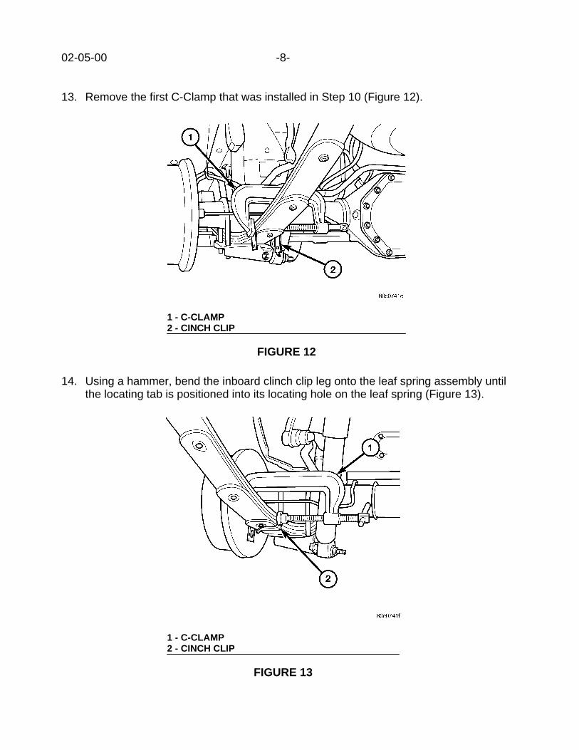
13. Remove the first C-Clamp that was installed in Step 10 (Figure 12).
14. Using a hammer, bend the inboard clinch clip leg onto the leaf spring assembly untilthe locating tab is positioned into its locating hole on the leaf spring (Figure 13).
1 - C-CLAMP2 - CINCH CLIP
FIGURE 12
1 - C-CLAMP2 - CINCH CLIP
FIGURE 13

-9- 02-05-00
15. Next, bend the outboard clinch clip leg onto the leaf spring.16. Secure the clinch clip by bending the locking tab over (Figure 14).
17. Perform Steps 1 through 16 to all clinch clips and spring tip liners.18. Lower the vehicle.
POLICY: Reimbursable within the provisions of the warranty.
TIME ALLOWANCE:Labor Operation No:
02-30-03-90 Liner, Spring Tip, Replace, 4X2 .................................................0.4 Hrs.02-30-03-91 Liner, Spring Tip, Replace, 4X4 .................................................0.6 Hrs.
FAILURE CODE: P8 - New Part
1 - C-CLAMP2 - CINCH CLIP LOCKING TAB3 - PUNCH
FIGURE 14


NUMBER: 02-006-00
GROUP: Suspension
DATE: Oct. 27, 2000
This bulletin is supplied as technical information only and is not an authorization for repair. No part of this publication may be reproduced, stored in a retreival system,or transmitted, in any form or by any means, electronic, mechanical, photocopying, or otherwise, without written permission of DaimlerChrysler Corporation.
SUBJECT:Upper Control Arm Bushing Service
OVERVIEW:This bulletin provides service procedures for the removal and installation of the upper controlarm bushing.
MODELS:
1997 - 2000 (AN) Dakota
1998 - 2000 (DN) Durango
NOTE: THIS BULLETIN APPLIES TO 4X2 VEHICLES.
DISCUSSION:It is no longer necessary to replace the upper control arm assembly to service just the uppercontrol arm bushings. Upper control arm bushing p/n 52037673 is now available throughMopar. The following Repair Procedure provides upper control arm bushing removal andinstallation information. Special Tool 8441 is required to remove and install upper controlarm bushings and is now available through Miller Special Tools.
PARTS REQUIRED:
Qty. Part No. Description
2 52037673 Bushing, Upper Control Arm
EQUIPMENT REQUIRED:
8441 Remover/Installer - Upper Control Arm Bushing
REPAIR PROCEDURE:UPPER CONTROL ARM BUSHING REMOVAL1. Remove the control arm from the vehicle. Refer to the appropriate Service Manual or the
service information provided in the MDS2, Group 02, REMOVAL AND INSTALLATION -UPPER SUSPENSION ARM - REMOVAL.
2. Mount the control arm securely in a vise.3. Remove the nut and washer from the upper control arm pivot bar shaft.4. Install Special Tool 8441, Upper Control Arm Bushing Remover/Installer (Fig. 1).

02-006-00 -2-
Fig. 1 BUSHING REMOVAL
1 - 8441-1
2 - 8441-2
3 - 8441-3
5. Press out the old bushings.UPPER CONTROL ARM BUSHING INSTALLATION1. Slide the bushing over the pivot bar shaft and insert it into the control arm.2. Install Special Tool 8441, Upper Control Arm Bushing Remover/Installer (Fig. 2).
Fig. 2 BUSHING INSTALLATION
1 - 8441-1
2 - 8441-4
3. Press the bushing into the control arm.4. Install the washer and nut onto the upper control arm pivot bar shaft. Tighten the nut to
167 N·m (130 ft. lbs.).

-3- 02-006-00
CAUTION: ENSURE THAT THE SELF-LOCKING FEATURE OF THE NUT IS STILLFUNCTIONAL. REPLACE THE NUT ANYTIME THE SELF-LOCKING FEATURE DOESNOT FUNCTION AS DESIGNED.
5. Remove the control arm from the vise.6. Install the control arm in the vehicle. Refer to the appropriate Service Manual or the
service information provided in the MDS2, Group 02, - REMOVAL AND INSTALLATION- UPPER SUSPENSION ARM - INSTALLATION.
7. Align the front suspension. Refer to the appropriate Service Manual or the service infor-mation provided in the MDS2, Group 02, ALIGNMENT.
POLICY:Reimbursable within the provisions of the warranty.
TIME ALLOWANCE:
Labor Operation No:
02-10-57-02 Replace Upper Control Arm Bushing, Right Side 1.7 Hrs.
02-10-57-03 Replace Upper Control Arm Bushing, Left Side 1.7 Hrs.
FAILURE CODE:
11 Broken or Cracked
37 Excessive Wear
68 Noisy

NUMBER: 02–007–00
GROUP: Suspension
DATE: Dec. 8, 2000
This bulletin is supplied as technical information only and is not an authorization for repair. No part of this publication may be reproduced, stored in a retreival system,or transmitted, in any form or by any means, electronic, mechanical, photocopying, or otherwise, without written permission of DaimlerChrysler Corporation.
SUBJECT:Ticking Noise From The Front Strut Area
OVERVIEW:This bulletin involves replacing the front strut insulator if nescessary.
MODELS:
2001 (ST) Sebring/Stratus Coupe
NOTE: THIS INFORMATION APPLIES TO VEHICLES BUILT PRIORTO JULY 24, 2000 (MDH0724XX).
SYMPTOM/CONDITION:A light ticking noise may be heard when driving over moderately bumpy to rough roadsurfaces. The noise may sound like it is coming from the instrument panel area.
DIAGNOSIS/REPAIR PROCEDURES:Make note of the conditions that the customer describes and attempt to drive the vehicleto duplicate the condition. If necessary, have the customer demonstrate the condition.This will also help in verifying the repair once it has been made.
PARTS REQUIRED:
Qty. Part No. Description
AR (2) MR297465 Insulator, Front Strut
EQUIPMENT REQUIRED:
MB991176 Spanner
NPN Strut Compressor
REPAIR PROCEDURE:1. Remove the front strut that is making the noise following procedures listed in the
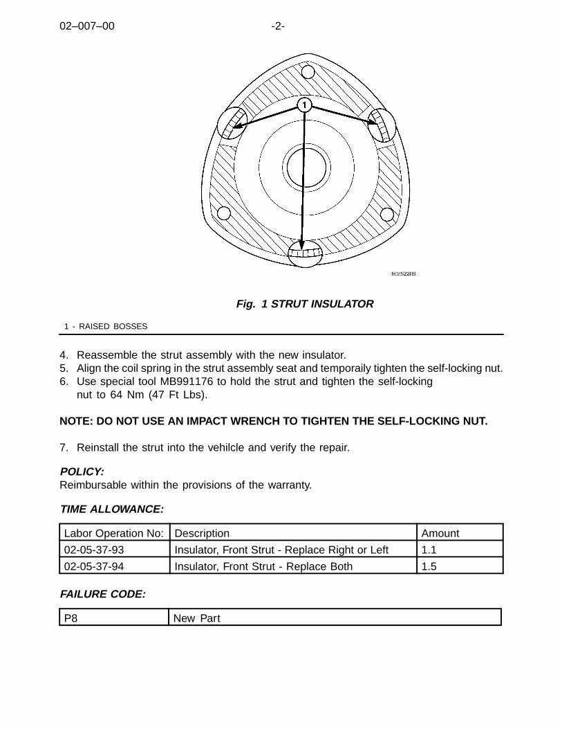
Sebring/Stratus Coupe service manual p/n 81–270–1018.2. Disassemble the strut to the point of insulator replacement.3. Replace the insulator with with the revised component p/n MR297465. It is
important to note that the part number for the insulator did not change. The revisedinsulator incorporates 3 raised bosses as shown (Fig. 1).
02–007–00 -2-
Fig. 1 STRUT INSULATOR
1 - RAISED BOSSES
4. Reassemble the strut assembly with the new insulator.5. Align the coil spring in the strut assembly seat and temporaily tighten the self-locking nut.6. Use special tool MB991176 to hold the strut and tighten the self-locking
nut to 64 Nm (47 Ft Lbs).
NOTE: DO NOT USE AN IMPACT WRENCH TO TIGHTEN THE SELF-LOCKING NUT.
7. Reinstall the strut into the vehilcle and verify the repair.
POLICY:Reimbursable within the provisions of the warranty.
TIME ALLOWANCE:
Labor Operation No: Description Amount
02-05-37-93 Insulator, Front Strut - Replace Right or Left 1.1
02-05-37-94 Insulator, Front Strut - Replace Both 1.5
FAILURE CODE:
P8 New Part
NUMBER: 02-008-00
GROUP: Suspension
DATE: Dec. 15, 2000
This bulletin is supplied as technical information only and is not an authorization for repair. No part of this publication may be reproduced, stored in a retreival system,or transmitted, in any form or by any means, electronic, mechanical, photocopying, or otherwise, without written permission of DaimlerChrysler Corporation.
SUBJECT:Vehicle Leads or Pulls
OVERVIEW:This bulletin covers the diagnosis and repair information for vehicles thathave a constant pull or lead condition.
MODELS:
2001 (LH) Concorde/Intrepid/LHS/300M
SYMPTOM/CONDITION:Vehicle has a constant lead or pull on a flat non-crowned road.
DIAGNOSIS:To assure correct diagnosis, it is important to follow the steps outlined below in the ordershown. Road test the vehicle before and after each step to verify that the lead condition hasbeen corrected. When evaluating a vehicle, always drive the same road in both directions toget a feel for the effect of road crown and cross wind. A neutral vehicle will exhibit a smallamount of drift on both right and left crowned roads (normal crown sensitivity). A vehiclewith pronounced lead/pull may have one or more of the following conditions:
1. UNEQUAL TIRE PRESSURE – Adjust tire pressure to the pressure stated ondoor placard. Make sure the tire pressure is equal on all four tires and evaluatethe car. Also note that the tire size and type are correct and match eachother. If the car still has a lead condition go to step 2.
2. TIRE CONICITY – Excessive tire conicity is one of the more frequent causes of vehiclelead. Cross switch the front tires and evaluate the car. If the car still leads in the samedirection or gets worse, return the front tires to their original position, and go to step 3.
3. SUSPENSION ALIGNMENT – Check and record the vehicle alignment settingsincluding caster. Non symmetrical front caster or camber can sometimes cause a leadcondition or can be used to fix a lead condition. To bias the front suspension casterand/or camber alignment settings to correct or minimize a lead condition perform theRepair Procedure. If the car still leads after the alignment bias procedure, go to step 4.
4. STEERING GEAR VALVE IMBALANCE – Steering gear valve imbalance cansometimes cause a vehicle lead. Although there is no quick test or measurement thatcan be performed to verify a good or bad steering gear valve, generally the steeringefforts will feel much lighter in the lead direction and heavier in the opposite directionwith an unbalanced valve. Replace the steering gear only as a "last resort" to solve theproblem. To replace the steering gear follow the procedure in Group 19 of the 2001Concorde/Intrepid/LHS/300M Service Manual (Publication No. 81-270-1040).
02-008-00 -2-
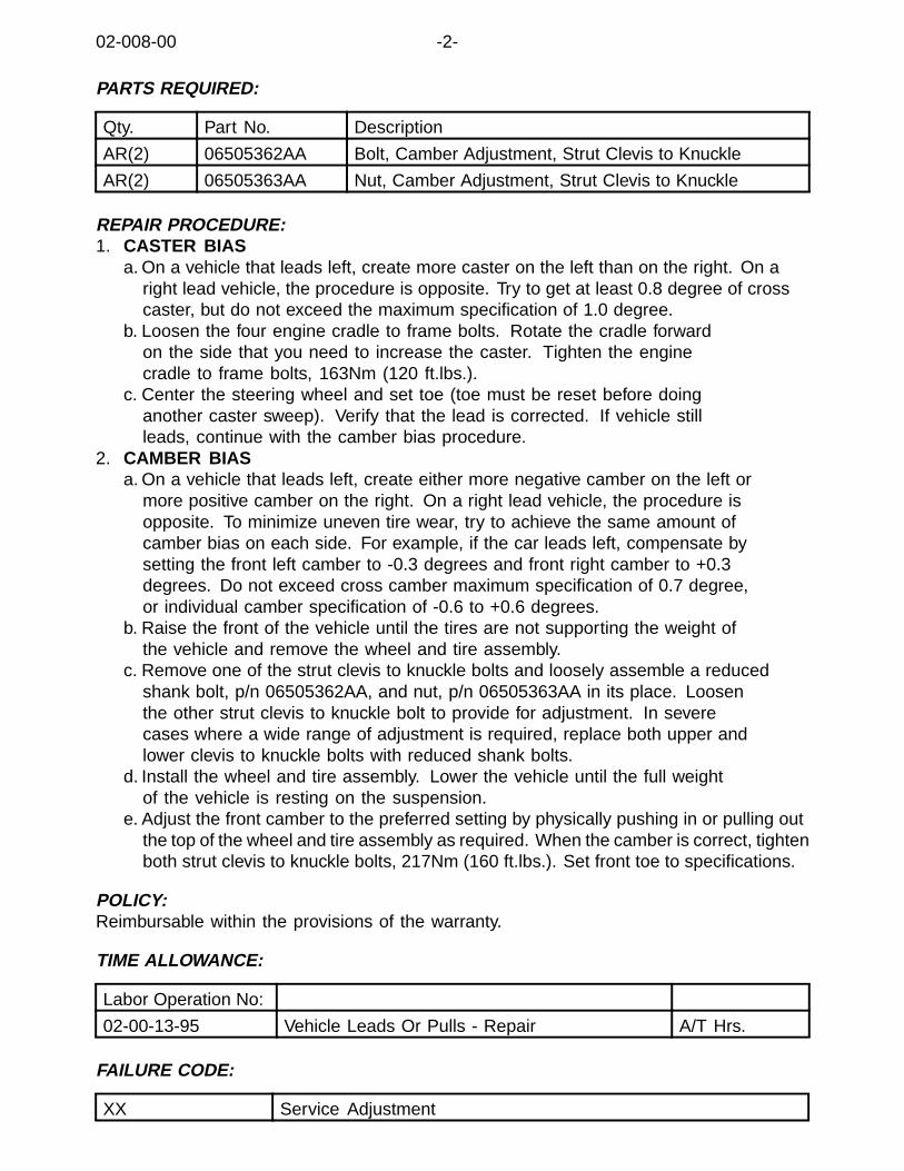
PARTS REQUIRED:
Qty. Part No. Description
AR(2) 06505362AA Bolt, Camber Adjustment, Strut Clevis to Knuckle
AR(2) 06505363AA Nut, Camber Adjustment, Strut Clevis to Knuckle
REPAIR PROCEDURE:1. CASTER BIAS
a. On a vehicle that leads left, create more caster on the left than on the right. On aright lead vehicle, the procedure is opposite. Try to get at least 0.8 degree of crosscaster, but do not exceed the maximum specification of 1.0 degree.
b. Loosen the four engine cradle to frame bolts. Rotate the cradle forwardon the side that you need to increase the caster. Tighten the enginecradle to frame bolts, 163Nm (120 ft.lbs.).
c. Center the steering wheel and set toe (toe must be reset before doinganother caster sweep). Verify that the lead is corrected. If vehicle stillleads, continue with the camber bias procedure.
2. CAMBER BIASa. On a vehicle that leads left, create either more negative camber on the left or
more positive camber on the right. On a right lead vehicle, the procedure isopposite. To minimize uneven tire wear, try to achieve the same amount ofcamber bias on each side. For example, if the car leads left, compensate bysetting the front left camber to -0.3 degrees and front right camber to +0.3degrees. Do not exceed cross camber maximum specification of 0.7 degree,or individual camber specification of -0.6 to +0.6 degrees.
b. Raise the front of the vehicle until the tires are not supporting the weight ofthe vehicle and remove the wheel and tire assembly.
c. Remove one of the strut clevis to knuckle bolts and loosely assemble a reducedshank bolt, p/n 06505362AA, and nut, p/n 06505363AA in its place. Loosenthe other strut clevis to knuckle bolt to provide for adjustment. In severecases where a wide range of adjustment is required, replace both upper andlower clevis to knuckle bolts with reduced shank bolts.
d. Install the wheel and tire assembly. Lower the vehicle until the full weightof the vehicle is resting on the suspension.
e. Adjust the front camber to the preferred setting by physically pushing in or pulling outthe top of the wheel and tire assembly as required. When the camber is correct, tightenboth strut clevis to knuckle bolts, 217Nm (160 ft.lbs.). Set front toe to specifications.
POLICY:Reimbursable within the provisions of the warranty.
TIME ALLOWANCE:
Labor Operation No:
02-00-13-95 Vehicle Leads Or Pulls - Repair A/T Hrs.
FAILURE CODE:
XX Service Adjustment

NUMBER: 02-009-00
GROUP: Suspension
DATE: Dec. 29, 2000
This bulletin is supplied as technical information only and is not an authorization for repair. No part of this publication may be reproduced, stored in a retreival system,or transmitted, in any form or by any means, electronic, mechanical, photocopying, or otherwise, without written permission of DaimlerChrysler Corporation.
SUBJECT:Popping or Squawking Noise From Rear Suspension
OVERVIEW:This bulletin involves diagnosing and if necessary replacing rear upper control arms.
MODELS:
2001 (JR) Sebring Sedan/Stratus Sedan/Sebring Convertible
SYMPTOM/CONDITION:Popping or squawking noise from rear suspension while driving vehicle. Noisecan be mistaken for a strut or strut mount condition.
DIAGNOSIS:Play in the rear suspension upper control arm bushing may be caused by improperlyinstalled bushings (Fig. 1). If the bushing is not visually improperly installed, place apry bar between the control arm and lip of the bushing. Apply light to moderate force,if there is any movement between the two, perform the Repair Procedure.

02-009-00 -2-
Fig. 1 REAR UPPER CONTROL ARM BUSHING
1 - PROPERLY INSTALLED BUSHING
2 - IMPROPERLY INSTALLED BUSHING
PARTS REQUIRED:
Qty. Part No. Description
AR(1) 04764962AB Upper Control Arm, Rear, Right
AR(1) 04764963AB Upper Control Arm, Rear, Left
REPAIR PROCEDURE:Replace the upper control arm assembly(s) as described on page 2–50 of the 2001Sebring/Stratus Sedan Service Manual (Pub. No. 81-270-1021).
POLICY:Reimbursable within the provisions of the warranty.
TIME ALLOWANCE:
Labor Operation No:
02-30-05-90 Arm, Rear Suspension/Control - Replace One 1.5 Hrs.
02-30-05-91 Arm, Rear Suspension/Control - Replace Both 1.8 Hrs.
Optional Procedure
02-30-05-60 Antilock Brakes Equipped 0.1 Hrs.
FAILURE CODE:
P8 New Part

2000 INDEX
GROUP 03REAR AXLE
BULLETIN SUBJECT MODELS TSB NO.
GROUP 03 - REAR AXLE
Driveshaft Removal Information 2000 JA,JX,PL, 2001 PT 03-01-00
9.25 Axle Gear Marking Compound Causes AMilky-Like Appearance To the Axle Fluid
1999 - 2000 AB,AN,BR/BE,DN 03-02-00
A Whine-Like Sound Heard From Rear Of TheVehicle At Speeds Greater Than 40 MPH
1999 - 2000 WJ 03-03-00
An Intermittent Bump Felt Shortly After The Ve-hicle Has Come To A Full Stop
1999 - 2000 WJ 03-04-00
Quality Improvements to Address Front AxleWhine And 2,400 RPM Moan
1999 - 2000 WJ 03-05-00
Sound Coming From The Front Axle During Ac-celeration At Vehicle Speeds Between 5 to 30MPH
2000 AN,DN 03-06-00
Noise/Vibration In Drivetrain And/Or Front Pro-peller Shaft Constant Velocity Boot Integrity
2001 - AN,DN 03-07-00
RTV Use On Corporate Axle 1998 - 2001 AB,AN,BR/BE,DN,XJ
03-08-00


Form TSB-004 Rev. 1.05
NUMBER: 03-01-00
GROUP: Driveshafts
DATE: Feb. 4, 2000
SUBJECT:Driveshaft Removal Information
MODELS:2000 (JA) Breeze/Cirrus/Stratus2000 (JX) Sebring Convertible2000 (PL) Neon2001 (PT) PT Cruiser
DISCUSSION:During any service that requires the removal of the driveshaft, it is extremely important thatthe driveshaft removal procedure in Group 3 of the appropriate service manual befollowed. The Neon and PT Cruiser Service Manuals provide the instructions for theproper use of a puller (Tool 6790); this puller must be used. Do not hammer on the endof the CV joint to detach the steering knuckle from the shaft. This can cause internaldamage to the shaft that may not be obvious until the completion of the repair.
POLICY: Information Only
This bulletin is supplied as technical information only and is not an authorization for repair. No part of this publication may be reproduced, stored in a retrieval system, ortransmitted, in any form or by any means, electronic, mechanical, photocopying, recording, or otherwise, without written permission of DaimlerChrysler Corporation.

Form TSB-004 Rev. 1.06 February 3, 2000
NUMBER: 03-02-00
GROUP: Axles
DATE: Mar. 03, 2000
SUBJECT:9.25 Axle Gear Marking Compound Causes A Milky-Like Appearance To The Axle Fluid
MODELS:1999 – 2000 (AB) Ram Van1999 – 2000 (AN) Dakota1999 – 2000 (BR/BE) Ram Truck1999 – 2000 (DN) Durango
NOTE: THIS BULLETIN APPLIES TO VEHICLES EQUIPPED WITH A 9.25 INCHREAR AXLE AND BUILT BETWEEN NOV. 1, 1998 (MDH 1101XX) AND NOV.1, 1999 (MDH 1101XX).
DISCUSSION:The customer or servicing technician may notice a milky-like appearance to the 9.25 inchrear axle fluid. This condition may be brought to the customer’s attention when the axlefluid is inspected during normal service. Other than the concern for the color of axle fluid,the customer does not experience any other axle complaint. The customer or servicingtechnician may be concerned because a milky-like appearance to the axle fluid may alsoindicate the presence of water.
The cause of the milky-like appearance to the axle fluid may be due to the use of a whitecolor gear marking compound during the axle assembly process. Axle gear markingcompound is used to verify correct ring and pinion gear alignment during manufacture.The 9.25 inch rear axle is assembled on two different assembly lines. To visuallydistinguish axles from each assembly line, one assembly line used a white color gearmarking compound (versus yellow). Half of the axles that were assembled during theabove time frame may have the white gear marking compound mixed with the rear axlefluid. The white color gear marking compound is no longer in use by the axle assemblyplant.
NOTE: IF THE MILKY-LIKE REAR AXLE FLUID APPEARANCE IS DUE TO THEWHITE GEAR MARKING COMPOUND, THEN NO SERVICE ACTION ISNECESSARY TO ADDRESS THIS CONDITION.
If the milky-like rear axle fluid appearance is due to the presence of water, then the rearaxle will require service. Axle fluid, contaminated with water, may cause rust and damageto the internal components of the axle.
Any water in the axle fluid will begin to boil off (reach its gaseous state) before the oil.Placing a small sample of axle fluid on a hot steel surface (around 100C or 212F) willcause any water that may be present in the fluid to boil off with a “sizzle-like” sound.
POLICY: Information Only
This bulletin is supplied as technical information only and is not an authorization for repair. No part of this publication may be reproduced, stored in a retrieval system, ortransmitted, in any form or by any means, electronic, mechanical, photocopying, recording, or otherwise, without written permission of DaimlerChrysler Corporation.


Form TSB-003 Rev. 1.08 February 3, 2000
NUMBER: 03-03-00
GROUP: Axle & Propeller Shaft
DATE: March 10, 2000
SUBJECT:A Whine-Like Sound Heard From Rear Of the Vehicle At Speeds Greater Than 40 MPH.
OVERVIEW:This bulletin involves the installation of a dampened rear propeller shaft.
MODELS:1999 – 2000 (WJ) Grand Cherokee
NOTE: THIS BULLETIN APPLIES TO VEHICLES EQUIPPED WITH A 4.7L ENGINEBUILT BEFORE NOVEMBER 16, 1999 (NVH 1116XX).
SYMPTOM/CONDITION:A whine-like sound may be heard coming from the rear axle area of the vehicle at speedsgreater than 40 mph (64 Km/h). The sound may be more noticeable once the vehiclepowertrain components have reached normal operating temperatures.
DIAGNOSIS:Road test the vehicle to confirm the condition.
NOTE: A THOROUGH ROAD TEST AND DIAGNOSIS MAY BE REQUIRED. REFERTO TECHNICAL SERVICE BULLETIN (TSB) 03-05-99 FOR ADDITIONALDIAGNOSTIC ASSISTANCE.
If the above condition is present, then perform the Repair Procedure. If the condition is notpresent, or if there is still significant rear axle generated sound present after the followingRepair Procedure has been performed, then further axle diagnosis may be required.
NOTE: THIS REPAIR, BY ITSELF, WILL NOT CORRECT SIGNIFICANT REAR AXLEGENERATED SOUND. IN THOSE INCIDENCES, THIS REPAIR MAY BEMOST BENEFICIAL WHEN PERFORMED WITH AN AXLE REBUILD REPAIR.
PARTS REQUIRED:1 52099487AC Rear propeller shaft (WJ - 4.7L with a NV-247 transfer case)1 52111490AB Rear propeller shaft (WJ - 4.7L with a NV-242HD transfer case)1 52099486AC Rear propeller shaft (WJ – 4.7L with no transfer case - 4x2)
REPAIR PROCEDURE:1. Partially raise and support the vehicle.2. Shift the transfer case to its Neutral position.3. Raise the vehicle completely.4. Remove the bolts holding the universal joint clamps to the pinion yoke.5. Slide the propeller shaft forward to free the rear universal joint from the pinion yoke.
This bulletin is supplied as technical information only and is not an authorization for repair. No part of this publication may be reproduced, stored in a retrieval system, ortransmitted, in any form or by any means, electronic, mechanical, photocopying, recording, or otherwise, without written permission of DaimlerChrysler Corporation.

03-03-00 -2-
6. Slide the slip yoke off the transfer case output shaft and remove the propeller shaft.7. Slide the new propeller shaft slip yoke onto the transfer case output shaft.8. Position the universal joint into the pinion yoke.9. Install the universal joint clamp and clamp bolts to the pinion yoke. Tighten the clamp
bolts to 19 Nm (14 ft. lbs.).10. Lower the vehicle.11. Shift the transfer case to its 2H position.
POLICY: Reimbursable within the provisions of the warranty.
TIME ALLOWANCE:Labor Operation No: 16-30-02-97 . ................................................................0.3 Hrs.
FAILURE CODE: P8 – New Part
Form TSB-003 Rev. 1.08 February 3, 2000
NUMBER: 03-04-00
GROUP: Axle & Propeller Shaft
DATE: June 23, 2000
THIS BULLETIN SUPERSEDES TECHNICAL SERVICE BULLETIN 03-07-99, DATEDOCT. 29, 1999, WHICH SHOULD BE REMOVED FROM YOUR FILES. ALL REVISIONSARE HIGHLIGHTED WITH **ASTERISKS** AND INCLUDE REVISED PART NUMBERS.
SUBJECT:An Intermittent Bump Felt Shortly After The Vehicle Has Come To A Full Stop
OVERVIEW:This bulletin involves replacement of the rear propeller shaft.
MODELS:1999 – 2000 (WJ) Grand Cherokee
NOTE: THIS BULLETIN APPLIES TO VEHICLES BUILT BEFORE SEPTEMBER 20,1999 (MDH 0920XX).
SYMPTOM/CONDITION:The vehicle owner may feel an intermittent bump (stop-bump) once the vehicle is broughtto a full stop. This condition may occur 3 to 20 seconds following the stop or when theload on the rear driveline is reduced (e.g. when the applied brake pressure is decreased).
The repair technician may erroneously diagnose this condition as a delayed transmissiondown shift into first gear.
DIAGNOSIS:The stop-bump condition may be the result of a binding between the splined surfaces ofthe rear propeller shaft slip yoke and the rear output shaft of either the transfer case or thetransmission. As load on the driveline is reduced, the bound slip yoke will releasesuddenly causing a bump-like sensation. The condition may be intermittent. If the abovecondition has been experienced, then perform the Repair Procedure.
The splined surfaces on the slip yoke section of the new propeller shaft are nickel coatedto reduce the opportunity of binding.
**NOTE: A WJ EQUIPPED WITH A 4.0L ENGINE, A NV242 TRANSFER CASE, AND A198 RBI (M35) REAR AXLE USES A DIFFERENT STYLE REAR PROPELLERSHAFT THAN THOSE WHICH ARE ADDRESSED IN THIS TECHNICALSERVICE BULLETIN. FOR THIS VEHICLE, THE SPLINED SURFACES ONTHE PROPELLER SHAFT SLIP YOKE AND THE TRANSFER CASE OUTPUTSHAFT ARE GREASED TO PREVENT A BINDING CONDITION AND DO NOTREQUIRE REPLACEMENT.**
This bulletin is supplied as technical information only and is not an authorization for repair. No part of this publication may be reproduced, stored in a retrieval system, ortransmitted, in any form or by any means, electronic, mechanical, photocopying, recording, or otherwise, without written permission of DaimlerChrysler Corporation.

03-04-00 -2-
PARTS REQUIRED:1 52099484AD Shaft, Drive (4.0L / 4x2 / 42RE / 198 RBI – M35)1 52099485AE Shaft, Drive (4.0L / 4x4 / 42RE / NV247 / 198 RBI – M35)**1 52099486AC Shaft, Drive (4.7L / 4x2 / 45RFE / 226 RBA – M44)****1 52099487AC Shaft, Drive (4.7L / 4x4 / 45RFE / NV247 / 226 RBA –M44)****1 52111483AB Shaft, Drive (4.0L / 4x4 / 42RE / NV247 / 226 RBA – M44)****1 52111490AB Shaft, Drive (4.7L / 4x4 / 45RFE / NV242HD / 226 RBA – M44)**
REPAIR PROCEDURE:1. Raise and support the vehicle.2. Shift the transmission and transfer case, if necessary, to their Neutral positions.3. Remove the bolts holding the universal joint clamps to the pinion yoke.4. Slide the propeller shaft forward to free the rear universal joint from the pinion yoke.5. Slide the slip yoke off the transmission, or transfer case, output shaft and remove the
propeller shaft.6. Slide the new propeller shaft slip yoke onto the transmission or transfer case output
shaft.7. Position the universal joint into the pinion yoke.8. Install the universal joint clamp and clamp bolts to the pinion yoke. Tighten the clamp
bolts to 19 Nm (14 ft. lbs.).9. Lower the vehicle.10. Shift the transmission and transfer case to their Park positions.
POLICY: Reimbursable within the provisions of the warranty.
TIME ALLOWANCE:Labor Operation No: 16-30-02-96 ................................................................0.3 Hrs.
FAILURE CODE: P8 – New Part

Form TSB-003 Rev. 1.08 February 3, 2000
NUMBER: 03-05-00
GROUP: Axle & Propeller Shaft
DATE: July 21, 2000
SUBJECT:Quality Improvements To Address Front Axle Whine And 2,400 RPM Moan
OVERVIEW:This bulletin involves the replacement of the front propshaft, axle yoke, and transfer caseyoke. This bulletin also involves selectively erasing and reprogramming the TransmissionControl Module or TCM (with calibration 99Ver9.0 or 00Ver9.0), and if necessary,reprogramming the Powertrain Control Module or PCM (with calibration 99Cal19A or00Cal16A).
MODELS:1999 – 2000 (WJ) Grand Cherokee
NOTE: THIS BULLETIN APPLIES TO VEHICLES EQUIPPED WITH A 4.7L ENGINEAND EITHER A NV247 OR A NV242HD TRANSFER CASE.
SYMPTOM/CONDITION:The customer may experience powertrain related sound(s) which may be described asfront axle whine or as 2,200 to 2,400 engine rpm moan. One or both sounds may benoticed at the same time or separately during different modes of driving.
The front axle whine-like sound may occur during any vehicle speed and duringacceleration, coast, or float driving modes.
The moan-like sound will normally occur when the transmission is in top gear (overdrive)and the engine is running between speeds of 2,200 to 2,400 rpm. The moan-like soundwill normally fade in and out (beat) while the throttle is held in a steady state or when thethrottle is being depressed to accelerate the vehicle. The beat may increase in frequencyas the engine speed increases. The moan-like sound will not occur if the transmission isshifted to a lower gear (overdrive button depressed) or if the throttle is released.
A revised front propeller shaft addresses the whine-like sound from the front axle area.
The revision to the TCM software adds a final gear ratio to the transmission. This newfinal gear ratio will cause a substantial reduction in the moan-like sound. Any remainingsound will occur at higher vehicle speeds.
NOTE: TO MAINTAIN EMISSIONS COMPLIANCE, VEHICLES EQUIPPED WITH AFEDERAL EMISSION SYSTEM (SALES CODE NAA) MUST HAVE THE PCMREPROGRAMMED IF THE PCM CALIBRATION LEVEL IS EARLIER THAN99CAL19A OR 00CAL16A. REPROGRAMMING IS NOT REQUIRED IF THEPCM SOFTWARE IS ALREADY AT ONE OF THESE LEVELS (OR LATER) ORIF THE VEHICLE HAS A CALIFORNIA EMISSION SYSTEM.
This bulletin is supplied as technical information only and is not an authorization for repair. No part of this publication may be reproduced, stored in a retrieval system, ortransmitted, in any form or by any means, electronic, mechanical, photocopying, recording, or otherwise, without written permission of DaimlerChrysler Corporation.

03-05-00 -2-
NOTE: WHENEVER A POWERTRAIN CONTROL MODULE OR A TRANSMISSIONCONTROL MODULE IS REPLACED DUE TO FAILURE, THE SOFTWARE OFTHE REPLACEMENT CONTROLLER MUST BE VERIFIED FOR THE LATESTREVISION LEVEL. USE THE FLASH PROCEDURE TO UPDATE REPLACEDCONTROLLERS AS NECESSARY.
DIAGNOSIS:1. If one or both of the above symptoms has been experienced on the vehicle in
question, then perform the Repair Procedure.2. Refer to Technical Service Bulletin (TSB) 03-05-9 if additional axle diagnosis is
required.
PARTS REQUIRED:1 05019624AA Yoke, front axle pinion (FBI 186 / Mdl 30)1 05017755AA Nut, pinion gear2 J3240553 Strap, front pinion yoke to single cardan universal joint4 J4006928 Bolt, front pinion yoke strap1 05019514AA Yoke, transfer case front (NV-247 or NV-242HD transfer case)4 06034966 Bolt, transfer case yoke to double cardan universal joint1 05019616AA Propshaft, front (4.7L w/NV-247 or NV-242HD transfer case)
2(AR) 04669020 Label, Authorized Software Update1 04275086 Label, Authorized Modification
EQUIPMENT REQUIRED:1 6958 Yoke Holder1 NPN Dial Inch pound torque wrench1 NPN Dial Foot pound torque wrench
1 CH6000 Scan Tool (DRB III)1 CH7035 General Purpose Interface Bus Cable (GPIB)1 CH7000/7001 J1962 Cable1 MDS2
NOTE: THE MDS2 AND DRB III ARE REQUIRED TO PERFORM PART OF THISREPAIR. WHEN USING THE MDS2 AND THE DRB III, THE SYSTEM MUSTBE OPERATING AT CIS CD 2062 OR HIGHER.
REPAIR PROCEDURE:
Front Propeller Shaft Replacement:
NOTE: DO NOT EXECUTE THIS REPAIR PROCEDURE UNLESS THE CORRECTEQUIPMENT IS USED. PAY CLOSE ATTENTION TO REPAIR PROCEDURE.
NOTE: DO NOT USE AN IMPACT WRENCH TO TIGHTEN THE PINION ORTRANSFER CASE NUTS.

-3- 03-05-00
1. Raise and support the vehicle on safety stands. Make sure the steering wheel iscentered.
2. Shift the transmission and transfer case, if necessary, into the Neutral position.3. Remove both front wheels and tires from their respective axle hub/bearing.4. Remove both front brake calipers from their anchors. Support the brake calipers in a
correct manner so that, the caliper will not interfere with the rotation of the axle shafts.Do not allow the brake hose to support the caliper weight.
5. Make a mark so that the brake rotor and hub can be installed back to their originalposition to each other.
6. Remove both brake rotors.
NOTE: THE WHEEL/TIRE ASSEMBLY, BRAKE CALIPER, AND BRAKE ROTORMUST BE REMOVED FROM BOTH SIDES OF THE FRONT AXLE BEFORETHE ORIGINAL TOTAL TORQUE TO ROTATE (TTR) MEASUREMENT ISTAKEN IN STEP 15.
7. Remove the bolts holding the front CV joint of the front propeller shaft front to the frontaxle pinion companion flange.
8. Remove the bolts holding the rear CV joint of the front propeller shaft to the transfercase companion flange.
9. Remove the front propeller shaft.10. Remove the nut used to secure the transfer case front companion flange to the
transfer case front output shaft. Save the nut for assembly.11. Remove the transfer case front companion flange from the transfer case front output
shaft.12. Install the new transfer case front yoke (pn 05019514AA) and its attaching nut onto
the transfer case front output shaft.
NOTE: NEVER USE AN IMPACT WRENCH TO TIGHTEN THE TRANSFER CASE NUT.
13. Tighten the transfer case yoke nut to 122 – 176 Nm (90 – 130 ft. lbs.).14. At the front axle, rotate the pinion gear a minimum of 10 turns.15. Using a dial inch pound torque wrench attached to the front axle pinion nut, measure
the Total Torque to Rotate (TTR) of the front axle. This specific TTR will be themeasurement of the torque that is required to rotate the pinion and differential gears(with axle shafts in place). Record the TTR measurement for later use in steps 20,21, and 22.
NOTE: A MEASUREMENT OF THE FRONT AXLE TOTAL TORQUE TO ROTATEMUST BE TAKEN BEFORE THE ORIGINAL PINION NUT AND PINION YOKEIS REMOVED. THE ORIGINAL TTR MEASUREMENT MUST BE KNOWN TOPREVENT POSSIBLE PINION BEARING FAILURE DURING ASSEMBLY OFTHE NEW PINION YOKE TO THE FRONT AXLE PINION.
16. Remove the front axle pinion nut and companion flange.17. Install the new front axle pinion yoke (pn 05019624AA) and attaching pinion nut (pn
05017755AA).

03-05-00 -4-
18. Tighten the pinion nut until there is zero bearing end-play.
NOTE: NEVER USE AN IMPACT WRENCH TO TIGHTEN AN AXLE PINION NUT.
19. Measure the current Total Torque to Rotate value with the same dial inch poundtorque wrench used to obtain the original TTR measurement.
20. Slowly tighten the pinion nut in 6.8 Nm (5 ft. lbs.) increments until the original TTRvalue is obtained.
NOTE: MEASURE THE ROTATING TORQUE FREQUENTLY TO AVOID OVERCRUSHING THE COLLAPSIBLE SPACER.
21. Increase the torque on the pinion nut in 6 – 8 Nm (5 ft. lbs.) increments until the TTRhas increased by 0.22 – 0.56 Nm (2 – 5 in. lbs.) above the original TTR value.
22. Once the new TTR value (the original TTR + 2 to 5 in. lbs.) has been obtained, rotatethe pinion gear a minimum of ten times. Verify that the pinion rotates smoothly.Verify that the new TTR value has not changed.
23. Note the paint mark on the transfer case yoke, front axle pinion yoke, and at each endof the propeller shaft. The paint marks must be aligned (positioned next to eachother) to minimize propeller shaft runout and out-of-balance.
24. Install the front propeller shaft rear double cardan joint to the transfer case yoke.Make sure the paint marks are aligned with each other.
25. Tighten the four bolts (pn 06034966) connecting the transfer case yoke to the doublecardan joint to 27 Nm (20 ft. lbs.).
26. Install the single cardan joint to the front axle pinion yoke. Make sure the paint marksare aligned with each other.
27. Install the two front axle yoke straps (pn J3240553) and four attaching bolts (pnJ4006928).
28. Tighten the axle yoke strap bolts to 19 Nm (14 ft. lbs.).29. Verify proper axle fluid level.30. Install each front brake rotor to its original position/orientation on the hub. Make sure
each rotor is aligned with the mark made previously.31. Install the front brake calipers and wheels. Tighten the caliper slide pins to 29 – 41
Nm (21 – 30 ft. lbs.).32. Tighten the front wheel lug nuts to 115 – 150 Nm (85 – 115 ft. lbs.).33. If necessary, shift the transmission into the Park position and the transfer case into
the 4 All-Time position (NV247) or either 4 Full-Time or 2 WD (NV242HD).34. Lower the vehicle.
TCM and PCM Reprogramming:
NOTE: PERFORM A QUICK LEARN OF THE TRANSMISSION ONCE THE TCM ISREPROGRAMMED.

-5- 03-05-00
NOTE: ONLY VEHICLES WITH A FEDERAL EMISSIONS SYSTEM AND PCMSOFTWARE THAT IS EARLIER THAN CALIBRATION 99CAL19A OR00CAL16A REQUIRE REPROGRAMMING. VERIFY THE CURRENTCALIBRATION LEVEL OF THE PCM.
1. Log onto the MDS2 system.2. Connect the MDS2 and DRB III to the vehicle and switch the ignition key to “ON”.3. Use the arrow keys and select #2 CONNECT TO MDS2 on the DRB III MAIN MENU
SCREEN.4. Use the arrow keys and select #2 RUN MDS2 APPLICATION on the DRB III MAIN
MENU SCREEN.
NOTE: ONCE MDS2, DRB III, AND VEHICLE COMMUNICATION HAS BEENESTABLISHED, THE “CANNOT READ VIN FROM DRB III” MESSAGE (ONTHE MDS2) WILL BE REPLACED BY THE VEHICLE VIN. PRESS THE “OK”BUTTON ON THE MDS2 TO REQUEST A MDS2 SESSION FOR THEVEHICLE VIN INDICATED. PRESS THE “OK” BUTTON WHEN ASKED TOBEGIN SESSION.
5. Select the FLASH tab on the MDS2.6. Select READ PART NUMBERS FROM VEHICLE and click SHOW UPDATES on the
MDS2. Press the “OK” button.
NOTE: IN ABOVE STEPS #5 AND/OR #6, A MESSAGE MAY APPEAR THATINDICATES NO UPDATES ARE AVAILABLE. IF THIS OCCURS, MAKESURE YOUR DIAGNOSTIC EQUIPMENT IS OPERATING AT THE LATESTSOFTWARE LEVEL AS LISTED EARLIER IN THIS BULLETIN. IF THELATEST SOFTWARE IS INSTALLED, AND NO UPDATES ARE AVAILABLE,ANOTHER VEHICLE CONDITION EXISTS THAT WILL REQUIRE FURTHERINVESTIGATION.
7. Select the new software part number with the light pen and click UPDATECONTROLLER SOFTWARE.
8. The MDS2 and DRB III will prompt for any operator action needed during theremainder of the reprogramming process.
NOTE: DUE TO THE PCM AND THE TCM REPROGRAMMING PROCEDURE, A DTCMAY BE SET IN OTHER MODULES (PCM, TCM, BCM, MIC, SKIM) WITHINTHE VEHICLE IF SO EQUIPPED. SOME DTC’S MAY CAUSE THE MIL TOILLUMINATE. ALL DTC’S RELATE TO A LOSS OF COMMUNICATIONSWITH THE MODULE THAT IS BEING REPROGRAMMED. CHECK ALLMODULES, RECORD THE FAULTS, AND ERASE THESE FAULTS PRIORTO RETURNING THE VEHICLE TO THE CUSTOMER. ERASE ANY FAULTSIN THE PCM ONLY AFTER ALL OTHER MODULES HAVE HAD THEIRFAULTS ERASED.
NOTE: THE FOLLOWING STEPS ARE REQUIRED BY LAW.

03-05-00 -6-
9. Type the necessary information on the “Authorized Software Update Label” p/n04669020 (Figure 1). Attach a label to the TCM (EATX), and if reprogramming wasrequired, attach a label to the PCM (JTEC). Cover both labels with the clear plasticoverlay.
FIGURE 1_____________________
10. Type the necessary information on the “Authorized Modification Label” p/n 04275086and attach the label near the VECI label (Figure 2).
1
2 3 4
1 – CONTROL MODULE PART NUMBER (INSERT NEW P/N HERE)2 - CHANGE AUTHORITY: TSB XX-XX-XX3 - DEALER CODE: XXXXX4 - DATE: XX-XX-XX
FIGURE 2
POLICY: Reimbursable within the provisions of the warranty.
TIME ALLOWANCE:Labor Operation No:
16-30-03-90 (Replace front propeller shaft) ……………….……………….. 1.3 Hrs.08-19-50-99 (Reprogram TCM) ……………………….…………………….. 0.5 Hrs.08-19-44-94 (Reprogram PCM – Federal Emissions Only) …………...…. 0.5 Hrs.
FAILURE CODE: P8 – New PartFM – Flash Module

Form TSB-003 Rev. 1.08 February 3, 2000
NUMBER: 03-06-00
GROUP: Axle
DATE: August 11, 2000
SUBJECT:Sound Coming From The Front Axle During Acceleration At Vehicle Speeds between 5 to30 MPH.
OVERVIEW:This bulletin involves the replacement of the right side front axle bearing.
MODELS:2000 (AN) Dakota2000 (DN) Durango
NOTE: THIS BULLETIN APPLIES TO FOUR WHEEL DRIVE VEHICLES.
SYMPTOM/CONDITION:The customer may experience a repetitive whoop – whoop like sound coming from thefront axle. There have been some complaints of a scrapping, grinding, or chirping likesound that has been attributed to this condition. The sound will increase in frequency withvehicle speed. This sound will occur only during vehicle acceleration and normallybetween the vehicle speeds of 8 to 48 kph (5 to 30 MPH). The sound may be morenoticeable once the front axle has reached normal operating temperature.
DIAGNOSIS:Slowly accelerate the vehicle from a stop. If the sound is present during acceleration, thenperform the Repair Procedure.
PARTS REQUIRED:1 52111167AA Bearing, Front axle (C205) right side1 52069706 Seal, axle shaft seal right side1(AR) 05010320AA Fluid, axle
EQUIPMENT REQUIRED:8420 Puller AdapterC-3752 Slide HammerC-4660-A Bearing Removal Tool5063 InstallerC-4171 Handle
REPAIR PROCEDURE:1. Replace the right front (passenger side) axle shaft bearing. Refer to the 2000 Dakota
Service Manual (Publication No. 81-370-0010) or the Durango 2000 Service Manual(81-370-0016). Detailed technical instructions regarding the replacement of theDakota right front axle shaft bearing can be found on page 3-39 (Axle Shaft Seal andBearing). Durango instructions can be found on page 3-38 of its respective manual.
This bulletin is supplied as technical information only and is not an authorization for repair. No part of this publication may be reproduced, stored in a retrieval system, ortransmitted, in any form or by any means, electronic, mechanical, photocopying, recording, or otherwise, without written permission of DaimlerChrysler Corporation.
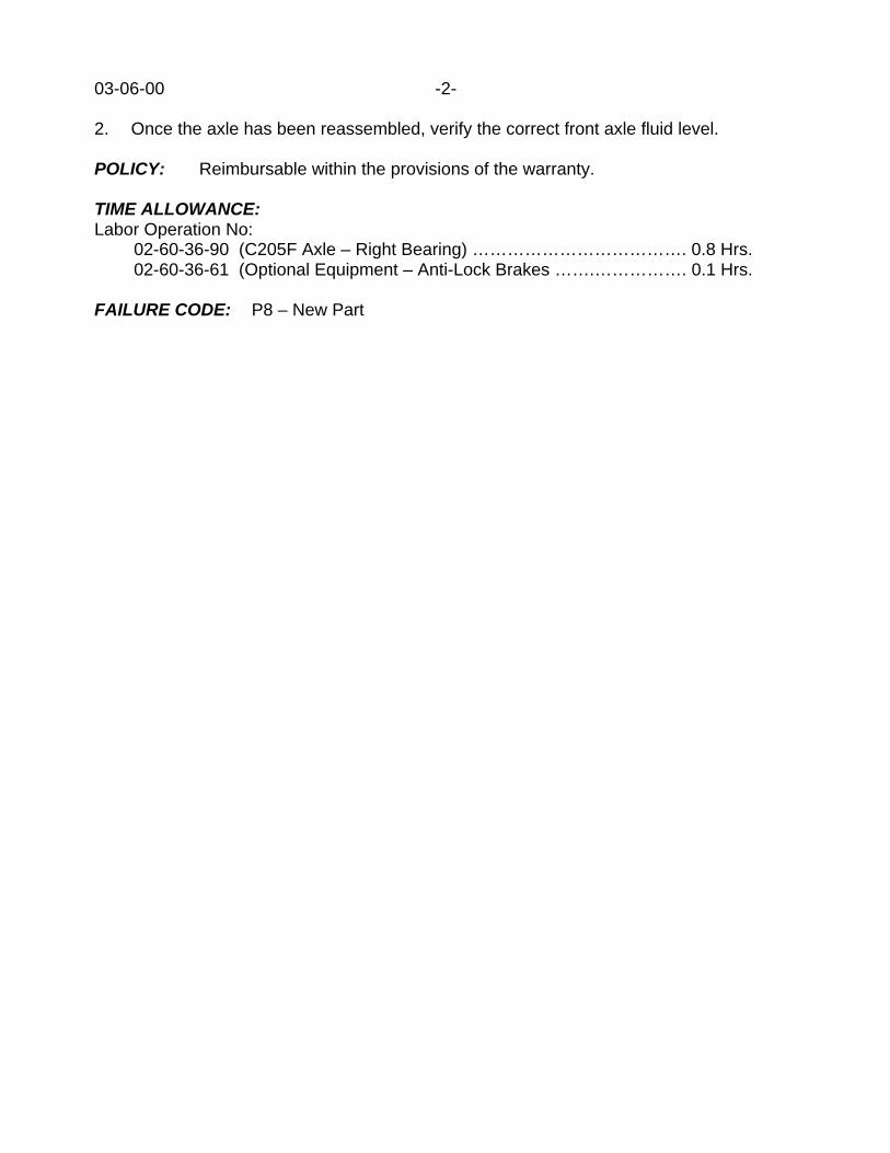
03-06-00 -2-
2. Once the axle has been reassembled, verify the correct front axle fluid level.
POLICY: Reimbursable within the provisions of the warranty.
TIME ALLOWANCE:Labor Operation No:
02-60-36-90 (C205F Axle – Right Bearing) ………………………………. 0.8 Hrs.02-60-36-61 (Optional Equipment – Anti-Lock Brakes …….……………. 0.1 Hrs.
FAILURE CODE: P8 – New Part
Form TSB-003 Rev. 1.08 February 3, 2000
NUMBER: 03-07-00
GROUP: Propeller Shaft
DATE: Sep. 8, 2000
SUBJECT:Noise/Vibration In Drivetrain And/Or Front Propeller Shaft Constant Velocity Boot Integrity
OVERVIEW:This bulletin involves the replacement of the front propeller shaft.
MODELS:2001 (AN) Dakota2001 (DN) Durango
NOTE: THIS BULLETIN APPLIES TO VEHICLES EQUIPPED WITH FOUR WHEELDRIVE BUILT BEFORE AUGUST 8, 2000 (MDH 0809XX).
SYMPTOM/CONDITION:Loss of lubricant may occur at the front propeller shaft constant velocity joint boot. Onepossible cause of this condition may be a partially crimped boot to the joint housing.Another cause of this condition may be a damaged (punctured) boot.
The customer may notice a noise, or a vibration, in the drivetrain while driving. Closerinspection of the front propeller shaft may reveal the spray of CV joint lubricant on to othervehicle components.
DIAGNOSIS:1. Raise and support the vehicle. Shift the transfer case into its Neutral position.2. Carefully inspect for a puncture or damage to the CV boot. Often the damage can be
located in the recessed (bend) area of the boot (Figure 1). The boot should be flexed,by rotating the propeller shaft. Close inspection may be required to locate thiscondition.
3. Carefully inspect the crimp used to secure the outer perimeter of the CV joint boot tothe CV joint housing (Figure 2).
4. If the front propeller shaft CV joint boot is damaged or partially crimped, then performthe Repair Procedure.
PARTS REQUIRED:1 52105981AC Shaft, Propeller (Manual Transmission)1 52105982AC Shaft, Propeller (Automatic Transmission)
REPAIR PROCEDURE:1. Using the appropriate Dakota or Durango Service Manual - Group 3, Propeller Shafts,
replace the front propeller shaft.
This bulletin is supplied as technical information only and is not an authorization for repair. No part of this publication may be reproduced, stored in a retrieval system, ortransmitted, in any form or by any means, electronic, mechanical, photocopying, recording, or otherwise, without written permission of DaimlerChrysler Corporation.

03-07-00 -2-
FIGURE 11 – Puncture To Constant Velocity Boot2 – Constant Velocity Joint On Front Propeller Shaft________________________________________
FIGURE 21 – Partial Crimp Of CV Joint Boot To Joint Housing2 – Constant Velocity Joint________________________________________
POLICY: Reimbursable within the provisions of the warranty.

-3- 03-07-00
TIME ALLOWANCE:Labor Operation No:
16-30-01-93 (Shaft, Replace Front) …………………………………………. 0.6 Hrs16-30-01-60 (Optional Skid Plate) ……………………………………..……. 0.2 Hrs
FAILURE CODE: P8 – New Part

Form TSB-004 Rev. 1.06 February 3, 2000
NUMBER: 03-08-00
GROUP: Axle & Propeller Shaft
DATE: Sep. 15, 2000
SUBJECT:RTV Use On Corporate Axle
MODELS:1998 - 2001 (AB) Ram Van1998 - 2001 (AN) Dakota1998 - 2001 (BR/BE) Ram Truck1998 - 2001 (DN) Durango1998 - 2001 (XJ) Cherokee
NOTE: THIS BULLETIN APPLIES TO ALL VEHICLES EQUIPPED WITH AN 8.25,9.25, OR C205F CORPORATE AXLE.
DISCUSSION:The axle lubricant used in all corporate axles was changed in formulation starting at thebeginning of the 1998 model year. The corporate axles involved include: the 8.25 and9.25 rear axles, and the C205F front axle. The new lubricant in use is SAE 75W-90 p/n05010320AA. The lubricant change was made as a fuel economy improvement.
The new axle lubricant is more chemically aggressive/reactive when in contact with theprevious used Room Temperature Vulcanizable (RTV) sealant. Because of this condition,the RTV used in assembly of the pan/cover to the axle housing was revised and improved.
When re-sealing axle covers, using the proper sealing material to minimize any potentialsealant breakdown is important. The only recommended sealing material for all corporateaxle covers is MOPAR RTV Sealant, p/n 05013477AA. This RTV is red/orange in color.
NOTE: IF SAE 75W-90 LUBRICANT IS USED TO REFILL ANY CORPORATE AXLE,THEN THE RED/ORANGE MOPAR RTV SEALANT, P/N 05013477AA,SHOULD BE USED TO SEAL THE COVER TO THE AXLE HOUSING.
To optimize sealant performance and enhance adhesion, flanges should be clean and freeof residual lubricant. The mating flanges should first be cleaned of any excess old RTVusing a plastic putty knife. Final cleaning/degreasing shall be done by spraying MOPARBrake Parts Cleaner, p/n 04549623, on the carrier and cover flanges, followed by a wipewith a clean dry cloth. Care should be taken to avoid spraying the parts cleaner inside thecarrier. Once the RTV has been applied, the axle cover is to be installed to the housingwithin 3 to 5 minutes to prevent skinning over of the RTV.
NOTE: IF THE AXLE COVER IS NOT INSTALLED WITHIN THE 3 TO 5 MINUTE TIMEFRAME, THE CARRIER COVER FACE MUST BE RECLEANED AND NEWRTV APPLIED, OR ADHESION QUALITY WILL BE COMPROMISED.
This bulletin is supplied as technical information only and is not an authorization for repair. No part of this publication may be reproduced, stored in a retrieval system, ortransmitted, in any form or by any means, electronic, mechanical, photocopying, recording, or otherwise, without written permission of DaimlerChrysler Corporation.

03-08-00 -2-
Immediately install the cover attaching bolts and tighten them to the specified torque toprevent a shimming effect by the RTV.
POLICY: Information Only

2000 INDEX
GROUP 05BRAKES
BULLETIN SUBJECT MODELS TSB NO.
GROUP 05 - BRAKES
Brake Roughness Or Pedal Pulsation When TheBrakes Are Applied
1999 - 2000 WJ 05-01-00 Rev. A
Revised Parking Brake Equalizer Assembly Re-moval Procedures
2001 PT 05-02-00
Proportioning Valve Brake Pressure Adapter ToolRevision
1995 - 1999 PL 05-03-00
High Pitched Squeal From Rear Brakes 2000 - BR/BE 05-04-00
Rear Brake Clunk Or Thump When Brakes AreApplied
1997 - 1998 XJ 05-05-00
Front Brake Caliper Anti-Rattle Clip Retainer Ser-vice Procedures
2000 - 2001 BR/BE 05-06-00
Rear Disc Brake Squeal 2001 RS 05-07-00

Form TSB-003 Rev. 1.07
NUMBER: 05-01-00 Rev A
GROUP: Brakes
DATE: April 14, 2000
THIS BULLETIN SUPERSEDES TECHNICAL SERVICE BULLETIN NUMBER 05-01-00,DATED MARCH 17, 2000, WHICH SHOULD BE REMOVED FROM YOUR FILES. THEBULLETIN ADDS AN ILLUSTRATION OMITTED FROM THE ORIGINAL. THECHANGES ARE HIGHLIGHTED WITH ASTERISKS.
SUBJECT:Brake roughness or pedal pulsation when the brakes are applied.
OVERVIEW:This bulletin involves installing a brake pad repair kit and turning the brake rotors with anon-car brake rotor lathe or replacing the rotors if on car equipment is not available.
MODELS:1999 - 2000 (WJ) Grand Cherokee
SYMPTOM/CONDITION:Customer may experience a vibration of the steering wheel, floor, seat, instrument panel ora minor pedal pulsation (brake roughness) under light to moderate pedal application. Thiscan be caused by excessive thickness variation on the rotor surface.
DISCUSSION:A new brake pad repair kit has been released which contains an adhesive backing. Thiswill provide for a more positive release of the brake pad when the brake pedal is released.This, in turn will move the pad away from the rotor, resulting in less friction and wear,which resulted from the pad resting on the rotor when the brakes were not applied.
The preferred method to reduce any variation at the brake rotor surface is to resurface therotors using an "On The Car" brake lathe such as the Pro-Cut lathe which is availablethrough Pentastar Service Equipment. This equipment does an excellent job of correctingall variation at the rotor surface. ”Off the Car" equipment can correct variation on the rotorsurface but does not correct for variation on other rotating components such as the hub.Situations can occur where a rotor and hub, mounted together, both within specifications,can stack up tolerances resulting in lateral runout, which can cause a pedal pulsation.
PARTS REQUIRED:1 05018592AA Brake Pad KitAR 52098672 Rotor
EQUIPMENT REQUIRED:Pro-Cut on car brake lathe (or equivalent) if available
This bulletin is supplied as technical information only and is not an authorization for repair. No part of this publication may be reproduced, stored in a retrieval system, ortransmitted, in any form or by any means, electronic, mechanical, photocopying, recording, or otherwise, without written permission of DaimlerChrysler Corporation.

05-01-00 Rev. A -2-
REPAIR PROCEDURE:
1. Remove the wheel and tire assembly.2. Remove the caliper support spring and discard the support spring.3. Remove the caliper from the anchor. Support the caliper with wire or string from a
suspension component. DO NOT allow the caliper to hang on the flexible brakehose or permanent hose damage may result. Retain the slide pins and slide pinbushing caps.
4. Remove the linings and discard.5. Remove and retain the anchor. Discard the anchor attaching bolts.6. Remove the rotors. If no on car lathe is available, the rotors should be discarded and
replaced.7. Clean the hub mounting face of the wheel bearing using a wire brush and/or fine emery
paper and rinse with brake cleaner. Take care to see that all corrosion andcontamination is removed.
8. Clean the paint and rust from the brake pad contact area of the anchor rails, using awire brush and/or fine emery paper and rinse with brake cleaner. (See FIGURE 1)
1. Clean and lubricate the areas indicated____________________________________
FIGURE 1
9. Clean the caliper slide pins and bushings.
THIS REPAIR IS COMPATIBLE WITH DAIMLERCHRYSLER'S MOBILE SERVICE PROGRAM ANDDOES NOT REQUIRE HOISTS OR OTHER FULL SERVICE FACILITY SPECIAL EQUIPMENT.
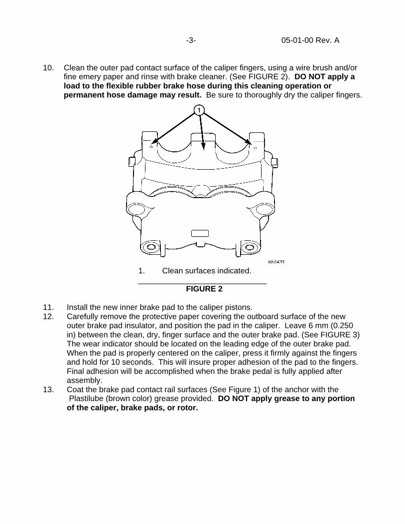
-3- 05-01-00 Rev. A
10. Clean the outer pad contact surface of the caliper fingers, using a wire brush and/orfine emery paper and rinse with brake cleaner. (See FIGURE 2). DO NOT apply aload to the flexible rubber brake hose during this cleaning operation orpermanent hose damage may result. Be sure to thoroughly dry the caliper fingers.
1. Clean surfaces indicated._____________________________
FIGURE 2
11. Install the new inner brake pad to the caliper pistons.12. Carefully remove the protective paper covering the outboard surface of the new
outer brake pad insulator, and position the pad in the caliper. Leave 6 mm (0.250in) between the clean, dry, finger surface and the outer brake pad. (See FIGURE 3)The wear indicator should be located on the leading edge of the outer brake pad.When the pad is properly centered on the caliper, press it firmly against the fingersand hold for 10 seconds. This will insure proper adhesion of the pad to the fingers.Final adhesion will be accomplished when the brake pedal is fully applied afterassembly.
13. Coat the brake pad contact rail surfaces (See Figure 1) of the anchor with the Plastilube (brown color) grease provided. DO NOT apply grease to any portionof the caliper, brake pads, or rotor.

05-01-0 Rev. A -4-
___________________________FIGURE 3 - PAD INSTALLATION
14. Coat the anti-rattle spring contact area of the anchor with Plastilube. (See FIGURE4)
1. Coat this area with Plastilube__________________________
** FIGURE 4 **

-5- 05-01-00 Rev. A
15. If On-Car rotor turning equipment such as the Pro-Cut lathe is available, install theoriginal rotors. Install new rotors if On-Car rotor turning equipment is not available.Install the new inner brake pad to the caliper pistons. Match mount the bearing androtor. Refer to the appropriate Jeep Grand Cherokee Service Manual to achieveminimum rotor lateral run out. The lateral runout of rotor and bearing shouldnot exceed 0.025 mm, (0.001 in).
16. If an On - Car brake lathe is available, turn the rotors using the lathe manufacturersrecommended procedures.
17. Install the anchor using the new attaching bolts. (anchor bolt torque 90-115 Nm,66-85 ft. lbs.). Take care not to get Plastilube on the rotor.
18. Carefully lubricate the caliper slide pins and slide pin bushings with the DC G807(white color) grease provided. It is not necessary to use all the grease provided.Take care not to get grease on the linings or rotor. Install the caliper, slide pins andbushing caps. (slide pin torque 29-41 Nm, 22-30 ft lbs.).
19. Reinstall the caliper, slide pins and bushing caps. (slide pin torque 29-41 Nm, 22-30 ft lbs.).
20. Install the new caliper support spring included in the kit. There should be Plastilubewhere the support spring contacts with the anchor.
21. Move the spring to its neutral position (along the axle axis) by lifting the endwith a screwdriver and releasing. Be careful to not bias the spring, as this willcause one or the other pads to tend to drag in an off-brake condition.
22. Repeat the entire procedure for the other front assembly.23. Upon completion of both front brake assemblies, apply firm pressure to the brake
pedal for 10 seconds to ensure proper final adhesion of the outer pad to the caliperfingers.
POLICY: Reimbursable within the provisions of the warranty.
TIME ALLOWANCE:Labor Operation No:
Install pads and turn rotors - on car05-21-11-94 ................................................................1.3 Hrs.
Optional Equipment Locking Axle - Add05-21-11-61 ................................................................0.2 Hrs.
Install pads, replace and match mount rotors05-21-10-94 ................................................................1.3 Hrs.
FAILURE CODE: P8 - New Part


Form TSB-004 Rev. 1.06 February 3, 2000
NUMBER: 05-02-00
GROUP: Brakes
DATE: April 7, 2000
SUBJECT:Revised Parking Brake Equalizer Assembly Removal Procedures
MODELS:2001 (PT) PT Cruiser
DISCUSSION:A new procedure has been developed to help ease the task of removing the centerconsole without putting excessive load on the parking brake equalizer assembly. Thisprocess will be used any time the parking brake equalizer assembly must be removedor installed. The PT Cruiser Service Manual (Publication Number 81-370-1111) will beupdated to reflect the new procedures. To assist with repairs until the manual updatesarrive the new procedures are provided in this Technical Service Bulletin. Theadditions to the procedure will be marked with **asterisks**.
Parking Brake Automatic Adjuster Lockout - PT Cruiser Service Manual Page 5-23
WARNING: THE AUTOMATIC ADJUSTING FEATURE OF THIS PARKING BRAKELEVER CONTAINS A CLOCKSPRING LOADED TO APPROXIMATELY19 POUNDS. DO NOT RELEASE THE AUTOMATIC ADJUSTERLOCKOUT DEVICE UNLESS THE REAR PARKING BRAKE CABLESAND EQUALIZER ARE CONNECTED TO THE LEVER OUTPUTCABLE. KEEP HANDS OUT OF AUTOMATIC ADJUSTER SECTORAND PAWL AREA. FAILURE TO OBSERVE CAUTION IN HANDLINGTHIS MECHANISM COULD LEAD TO SERIOUS INJURY.
WARNING: WHEN REPAIRS TO THE PARKING BRAKE LEVER OR CABLES AREREQUIRED, THE AUTOMATIC ADJUSTER MUST BE LOADED ANDLOCKED OUT TO AVOID POSSIBLE INJURY.
1. Block all four tire and wheels so the vehicle does not move once the vehicleparking brake lever is released.
2. Remove the transmission shifter knob as necessary.3. **Place the parking brake lever in its full "off" position.**4. **Remove the screws attaching the center console.**5. **Remove the rear window switch panel from the console.**6. **Through the switch panel opening, grasp a parking brake cable or equalizer
and pull back approximately one inch.**7. **While holding the cable or equalizer, pull the parking brake handle to its full
upright position.**8. **Remove the center console.**
This bulletin is supplied as technical information only and is not an authorization for repair. No part of this publication may be reproduced, stored in a retrieval system, ortransmitted, in any form or by any means, electronic, mechanical, photocopying, recording, or otherwise, without written permission of DaimlerChrysler Corporation.

05-02-00 -2-
9. Grasp the parking brake lever output cable by hand and pull upward. Continuepulling on the cable until an appropriate sized pin punch (drill bit or locking pin)can be inserted sufficiently through the hole in the left side of the lever mountingbracket (Fig. 39). This will lock the parking brake automatic adjustmentmechanism in place and take tension off the parking brake cables. Slowlyrelease the output cable. There should now be slack in the cables.
Unlocking Automatic Adjuster (Unloading) - PT Cruiser Service Manual Page 5-24
1. Be sure the rear parking brake cables are both properly installed in theequalizer.
2. **Raise the parking brake handle to its full "upright" position.**3. Keeping your hands clear of the automatic adjuster sector and pawl area, firmly
grasp the parking brake lever pin punch (drill bit or locking pin if a newmechanism is being installed) (Fig. 39), then quickly remove if from the parkingbrake lever mechanism. This will allow the park brake lever mechanism toautomatically adjust the parking brake cables.
4. Install the console and it's mounting screws.5. **Install the rear window switch panel.**6. Cycle the parking brake lever once to position the parking brake cables, then
return the parking brake lever to its released position.7. Remove the blocks from the rear wheels and slightly raise the rear of the
vehicle. Check the rear wheels of the vehicle, they should rotate freely withoutdragging with the lever in the released position.
8. Remove the blocks from the front tires and wheels.
Parking Brake Lever - Removal & Installation - PT Cruiser Service Manual Page 5-48
WARNING: THE AUTOMATIC ADJUSTING FEATURE OF THIS PARKING BRAKELEVER CONTAINS A CLOCK SPRING LOADED TOAPPROXIMATELY 19 POUNDS. DO NOT RELEASE THEAUTOMATIC ADJUSTER LOCKOUT DEVICE UNLESS THE REARPARKING BRAKE CABLES AND EQUALIZER ARE CONNECTED TOTHE LEVER OUTPUT CABLE. KEEP HANDS OUT OF AUTOMATICADJUSTER SECTOR AND PAWL AREA. FAILURE TO OBSERVECAUTION IN HANDING THIS MECHANISM COULD LEAD TOSERIOUS INJURY.

-3- 05-02-00
WARNING: WHEN REPAIRS TO THE PARKING BRAKE LEVER OR CABLES AREREQUIRED, THE AUTOMATIC ADJUSTER MUST BE LOADED ANDLOCKED OUT TO AVOID POSSIBLE INJURY.
WARNING: THE AIRBAG SYSTEM IS A COMPLEX ELECTROMECHANICAL UNIT.BEFORE ATTEMPTING TO SERVICE ANY COMPONENT NEAR THEOCCUPANT RESTRAINT CONTROLLER (ORC), FIRST DISCONNECTAND ISOLATE THE BATTERY NEGATIVE CABLE. ALLOW THESYSTEM CAPACITOR TO DISCHARGE FOR TWO (2) MINUTES.FAILURE TO DO THIS COULD RESULT IN ACCIDENTAL AIRBAGDEPLOYMENT AND POSSIBLE PERSONAL INJURY.
Removal:1. Unclip the air cleaner cover (two clips) and move the cover aside.2. Disconnect and isolate the battery negative cable from its post on the battery.3. Block all four tire and wheels so the vehicle does not move once the vehicle
parking brake lever is released.4. Remove the transmission shift knob as necessary.5. **Place the parking brake lever in its full "off" position.**6. **Remove the screws attaching the center console.**7. **Remove the rear window switch panel from the console.**8. **Through the switch panel opening, grasp a parking brake cable or equalizer
and pull back approximately one inch.**9. **While holding the cable or equalizer, pull the parking brake handle to its full
upright position.**10. **Remove the center console.**11. Grasp the parking brake lever output cable by hand and pull upward. Continue
pulling on the cable until an appropriate sized pin punch (drill bit or locking pin)can be inserted sufficiently through the hole in the left side of the lever mountingbracket (Fig. 94). This will lock the parking brake automatic adjustmentmechanism in place and take tension off the parking brake cables. Slowlyrelease the output cable. There should now be slack in the cables.
12. Remove both rear parking brake cables from the parking brake cable equalizer(Fig. 95).
13. Remove the wiring harness electrical connector from the parking brake warningswitch on the right side of the parking brake lever.
14. Remove the screw and the nut attaching the parking brake lever to the vehiclefloor.
15. Remove the parking brake lever from the vehicle.
Installation:1. Place the parking brake lever on the mounting stud on the vehicle floor. Install
and tighten the nut and screw to a torque of 28 Nm (250 in. lbs).

05-02-00 -4-
2. Connect the wiring harness electrical connector on the parking brake warningswitch.
3. Install both rear park brake cables into the equalizer on the parking brake leveroutput cable (Fig. 95).
4. Ensure that the parking brake cables are correctly installed on the equalizer andaligned with the cable track on the parking brake lever.
5. **Raise the parking brake handle to its full "upright" position.**6. Keeping your hands clear of the automatic adjuster sector and pawl area, firmly
grasp the parking brake lever pin punch (drill bit or locking pin if a newmechanism is being installed) (Fig. 94), then quickly remove if from the parkingbrake lever mechanism. This will allow the park brake lever mechanism toautomatically adjust the parking brake cables.
7. ** Install the center console and its mounting screws.**8. ** Install the rear window switch panel.**9. Cycle the parking brake lever once to position the parking brake cables, then
return the parking brake lever to its released position.10. Remove the blocks from the rear wheels and slightly raise the rear of the
vehicle. Check the rear wheels of the vehicle, they should rotate freely withoutdragging with the lever in the released position.
11. Apply the parking brake12. Remove the blocks from the front tires and wheels.13. Reconnect the battery negative terminal.14. Reinstall the air cleaner cover (two clips).
Parking Brake Cable - PT Cruiser Service Manual Pages 5-49, 5-50, 5-51 and 5-52
WARNING: THE AUTOMATIC ADJUSTING FEATURE OF THIS PARKING BRAKELEVER CONTAINS A CLOCK SPRING LOADED TOAPPROXIMATELY 19 POUNDS. DO NOT RELEASE THEAUTOMATIC ADJUSTER LOCKOUT DEVICE UNLESS THE REARPARKING BRAKE CABLES AND EQUALIZER ARE CONNECTED TOTHE LEVER OUTPUT CABLE. KEEP HANDS OUT OF AUTOMATICADJUSTER SECTOR AND PAWL AREA. FAILURE TO OBSERVECAUTION IN HANDING THIS MECHANISM COULD LEAD TOSERIOUS INJURY.
WARNING: WHEN REPAIRS TO THE PARKING BRAKE LEVER OR CABLES AREREQUIRED, THE AUTOMATIC ADJUSTER MUST BE LOADED ANDLOCKED OUT TO AVOID POSSIBLE INJURY.

-5- 05-02-00
WARNING: THE AIRBAG SYSTEM IS A COMPLEX ELECTROMECHANICAL UNIT.BEFORE ATTEMPTING TO SERVICE ANY COMPONENT NEAR THEOCCUPANT RESTRAINT CONTROLLER (ORC), FIRST DISCONNECTAND ISOLATE THE BATTERY NEGATIVE CABLE. ALLOW THESYSTEM CAPACITOR TO DISCHARGE FOR TWO (2)MINUTES.FAILURE TO DO THIS COULD RESULT IN ACCIDENTALAIRBAG DEPLOYMENT AND POSSIBLE PERSONAL INJURY.
NOTE: THE PROCEDURE BELOW APPLIES TO EITHER OF THE TWO REARPARKING BRAKE CABLES.
Removal:1. Unclip the air cleaner cover (two clips) and move the cover aside.2. Disconnect and isolate the battery negative cable from its post on the battery.3. Block all four tire and wheels so the vehicle does not move once the vehicle
parking brake lever is released.4. Remove the transmission shift knob as necessary.5. **Place the parking brake lever in its full "off" position.**6. **Remove the screws attaching the center console.**7. **Remove the rear window switch panel from the console.**8. **Through the switch panel opening, grasp a parking brake cable or equalizer
and pull back approximately one inch.**9. **While holding the cable or equalizer, pull the parking brake handle to its full
upright position.**10. **Remove the center console.**
Steps 6 through 22 of the removal procedures in the PT Cruiser Service Manual(Publication No. 81-370-1111) will be renumbered in the revision but the steps willremain the same. To complete the removal, begin on page 5-50 with step 6.
Installation:Steps one through 16 will remain the same, follow the installation procedure in the PTCruiser Service Manual (Publication No. 81-370-1111) page 5-52 up to step 16, andthen refer to the procedures below.
17. ** Raise the parking brake lever to its full "upright" position.**18. Keeping your hands clear of the automatic adjuster sector and pawl area, firmly
grasp the parking brake lever pin punch (drill bit or locking pin if a newmechanism is being installed) (Fig. 97), then quickly remove if from the parkingbrake lever mechanism. This will allow the park brake lever mechanism toautomatically adjust the parking brake cables.
19. **Install the console and its mounting screws.**20. ** Install the rear window switch panel.**21. Cycle the parking brake lever once to position the parking brake cables, then
return the parking brake lever to its released position.

05-02-00 -6-
22. Remove the blocks from the rear wheels and slightly raise the rear of thevehicle. Check the rear wheels of the vehicle, they should rotate freely withoutdragging with the lever in the released position.
23. Apply the parking brake.24. Remove the blocks from the front wheels and tires.25. Connect the battery negative terminal.26. Install the air cleaner cover using the two clips.
**Center Console** (Formally Floor Console) PT Cruiser Service Manual Pages23-61 & 23-62.
Removal:1. ** Block all four tire and wheels so the vehicle does not move once the vehicle
parking brake lever is released.**2. Remove the shift lever knob, if vehicle is equipped with a manual transmission
pull upward to remove. The automatic transmission shift lever knob has a setscrew that needs to be loosened and then pull up to remove the knob.
3. **Place the parking brake lever in its full "off" position.**4. **Remove the screws attaching the center console.**5. **Remove the rear window switch panel from the console.**6. **Through the switch panel opening, grasp a parking brake cable or equalizer
and pull back approximately one inch.**7. **While holding the cable or equalizer, pull the parking brake handle to its full
upright position.**8. Lift console to access power outlet wire connector and disconnect.9. **Remove the center console.**
Installation:1. Raise the parking brake to its full "upright" position.2. **Keeping your hands clear of the automatic adjuster sector and pawl area,
firmly grasp the parking brake lever pin punch (drill bit or locking pin if a newmechanism is being installed) (Fig. 97), then quickly remove if from the parkingbrake lever mechanism. This will allow the park brake lever mechanism toautomatically adjust the parking brake cables.**
3. Place the center console into position in the vehicle.4. Connect the power outlet connector and power window switches.5. Install the center console mounting screws.6. **Install the rear window switch panel.**7. Install the shift lever knob.**8. **Cycle the parking brake lever once to position the parking brake cables, then
return the parking brake lever to its released position.**9. **Remove the blocks from the rear wheels and slightly raise the rear of the
vehicle. Check the rear wheels of the vehicle, they should rotate freely withoutdragging with the lever in the released position.**

-7- 05-02-00
10. Apply the parking brake.11. Remove the blocks from the front wheels and tires.
POLICY: Information Only


Form TSB-004 Rev. 1.06 February 3, 2000
NUMBER: 05-03-00
GROUP: Brakes
DATE: April 14, 2000
SUBJECT:Proportioning Valve Brake Pressure Adapter Tool Revision
MODELS:1995 - 1999 (PL) Neon
DISCUSSION:Diagnosing and testing the brake proportioning valves following the procedure in theappropriate Neon Service Manual calls for the use of the Brake Pressure Adapter Set 6805and Brake Gauge Set C-4007-A. Alternate adapters from prior tool shipments should nowbe used on the Neon in place of the adapters provided in the Brake Pressure Adapter Set6805. When the Neon Service Manual calls for Adapter 6805-3, use Adapter 8187-2(Figure 1) which was shipped with the 1998 Concorde/Intrepid special tools in kit 8180CCor stored on panel 78. When the Neon Service Manual calls for Adapter 6805-4, useAdapter 6833-1 (Figure 1) which was shipped in the 1996 Minivan special tool kit andstored on panel 70. If you are unable to locate these adapters (6833-1 & 8187-2), they areavailable separately through Miller Special Tools (1-800-801-5420).
FIGURE 1____________________________________________
POLICY: Information Only
This bulletin is supplied as technical information only and is not an authorization for repair. No part of this publication may be reproduced, stored in a retrieval system, ortransmitted, in any form or by any means, electronic, mechanical, photocopying, recording, or otherwise, without written permission of DaimlerChrysler Corporation.


Form TSB-003 Rev. 1.07
NUMBER: 05-04-00
GROUP: Brakes
EFFECTIVE DATE: May 1, 2000
SUBJECT:High Pitched Squeal From Rear Brakes
OVERVIEW:This bulletin involves installing revised rear brake shoes.
MODELS:2000 (BR/BE) Ram Truck
NOTE: THIS BULLETIN APPLIES TO 2500/3500 SERIES RAM TRUCKS BUILTBEFORE MARCH 1, 2000 (MDH 0301XX).
SYMPTOM/CONDITION:A high pitched squeal comes from the rear brakes when the brakes are applied.
DIAGNOSIS:
NOTE: THE FOLLOWING DIAGNOSIS MUST BE PERFORMED WITH THE REARBRAKE DRUM TEMPERATURES LESS THAN 49OC. (120OF.) (MUST NOT BEHOT TO THE TOUCH).
Raise and support the rear axle. The axle should be supported so that the rear tires arecompletely off the ground.
CAUTION: 4X4 VEHICLES MUST HAVE THE TRANSFER CASE IN THE 4X2 MODE.
Start the engine. Put the transmission into gear and slowly raise the vehicle speed whileapplying light and steady pressure to the brake pedal. Attempt to reproduce the noise byapplying different pressures to the brake pedal a vehicle speeds of 8 - 16 kPh (5 - 10mph). If a high pitched squeal is heard coming from the rear brakes, perform the RepairProcedure.
NOTE: WITH THE VEHICLE RAISED, THE REAR WHEELS WILL LOCK-UP VERYQUICKLY WHEN THE BRAKES ARE APPLIED. IT IS RECOMMENDED TOUSE THE MIRRORS TO MONITOR TIRE ROTATION (LEFT AND RIGHT)DURING DIAGNOSIS.
PARTS REQUIRED:1 05015337AB Brake Shoes And Linings
This bulletin is supplied as technical information only and is not an authorization for repair. No part of this publication may be reproduced, stored in a retrieval system, ortransmitted, in any form or by any means, electronic, mechanical, photocopying, recording, or otherwise, without written permission of DaimlerChrysler Corporation.

05-04-00 -2-
REPAIR PROCEDURE:1. Remove and replace both right and left rear brake shoe and lining assemblies with p/n
05015337AB. Refer to the 2000 Ram Truck Service Manual (Publication No. 81-370-0008), pages 5-31 and 5-32, “Removal And Installation - Rear Brake Shoes - 12 1/8Inch.”
POLICY: Reimbursable within the provisions of the warranty.
TIME ALLOWANCE:Labor Operation No: 05-70-06-97 ................................................................0.7 Hrs.
Optional Equipment:05-70-06-60 Dual Rear Wheels ...................................0.2 Hrs.
FAILURE CODE: P8 - New part

Form TSB-003 Rev. 1.07
NUMBER: 05-05-00
GROUP: Brakes
DATE: May 26, 2000
SUBJECT:Rear brake clunk or thump when brakes are applied
OVERVIEW:This bulletin involves installing a rear axle shaft(s).
MODELS:1997 - 1999 (XJ) Cherokee
NOTE: THIS BULLETIN APPLIES TO VEHICLES EQUIPPED WITH AN 8 1/4INCH REAR AXLE.
SYMPTOM/CONDITION:A clunk or thump may be heard coming from the rear of the vehicle when the brakes areapplied on some vehicles equipped with an 8 1/4-inch rear axle. This may be caused byan axle shaft, which does not have a correct size brake drum pilot flange.
DIAGNOSIS:If the vehicle exhibits the condition, remove the rear wheels and brake drums and inspectthe rear axle shafts at the center pilot for the wheel and brake drum. There must be twoseparate pilot diameters on this area (See Figure 1). The outboard diameter for the wheel(2.812 -2.808 inches) and the slightly larger inner diameter to support the brake drum(2.832 -2.826 inches). The brake drum pilot may be missing or may not be deep enoughto support the drum. If the drum pilot does not adequately support the drum, somemovement of the drum may occur when the brakes are applied causing this noise. If thiscondition is present, perform the Repair Procedure.
1. Axle Flange2. Wheel Pilot3. Drum Pilot________________________________
FIGURE 2
This bulletin is supplied as technical information only and is not an authorization for repair. No part of this publication may be reproduced, stored in a retrieval system, ortransmitted, in any form or by any means, electronic, mechanical, photocopying, recording, or otherwise, without written permission of DaimlerChrysler Corporation.

05-05-00 -2-
PARTS REQUIRED:AR 05018393AA Shaft, Rear Axle
REPAIR PROCEDURE:1. Using the procedures outlined in the appropriate service manual, install a new axle
shaft or shafts, p/n 05018393AA, as necessary.2. Check and adjust fluid level if necessary.
POLICY: Reimbursable within the provisions of the warranty.
TIME ALLOWANCE:Labor Operation No: 03-20-01-95 ................................................................0.7 Hrs.
FAILURE CODE: P8 - New Part

Form TSB-004 Rev. 1.05
NUMBER: 05-06-00
GROUP: Brakes
DATE: June 9, 2000
SUBJECT:Front Brake Caliper Anti-Rattle Clip Retainer Service Procedures
MODELS:2000 - 2001 (BR/BE) Ram Truck
NOTE: THIS BULLETIN APPLIES TO VEHICLES BUILT BEFORE JUNE 26, 2000.
DISCUSSION:Vehicles built between April 19, 2000 and June 26, 2000 were built with a front brakecaliper anti-rattle clip retainer. This Technical Service Bulletin provides the installationprocedures for the retainer.
NOTE: FRONT BRAKE CALIPER ANTI-RATTLE CLIP LEADING EDGE RETAINER(LONG) P/N 05066175AA AND TRAILING EDGE RETAINER (SHORT) P/N05066176AA IS AVAILABLE FOR ALL SUBJECT RAM TRUCKS BUILTPRIOR TO JUNE 26, 2000. THESE RETAINERS CAN BE USED WITH THEVEHICLE’S EXISTING FRONT BRAKE ANTI-RATTLE CLIP TO HELP RETAINLOOSE ANTI-RATTLE CLIPS TO THE BRAKE CALIPER ADAPTER.
FRONT BRAKE CALIPER ANTI-RATTLE CLIP RETAINER INSTALLATIONPROCEDURE.
NOTE: THIS PROCEDURE IS SUPPLEMENTAL TO THE 2000 RAM TRUCKSERVICE MANUAL (PUBLICATION NO. 81-370-0008), PAGE 5-25, STEPS 4THROUGH 6 OF THE DISC BRAKE SHOE INSTALLATION PROCEDURE.THIS PROCEDURE SHOULD ONLY BE USED IF THE VEHICLE IS EQUIPPEDWITH FRONT BRAKE CALIPER ANTI-RATTLE CLIP RETAINERS.
1. Insert the anti-rattle clip retainer into the anti-rattle clip as shown in Figure 1.
NOTE: TO ACCOMMODATE THE WIDTH DIFFERENCES IN THE DISC BRAKECALIPER’S LEADING AND TRAILING ADAPTER RAILS, ONE RETAINER ISLONGER THAN THE OTHER. MAKE SURE THAT THE LONG RETAINER ISPLACED ON THE ANTI-RATTLE CLIP FOR THE LONG RAIL.
This bulletin is supplied as technical information only and is not an authorization for repair. No part of this publication may be reproduced, stored in a retrieval system, ortransmitted, in any form or by any means, electronic, mechanical, photocopying, recording, or otherwise, without written permission of DaimlerChrysler Corporation.
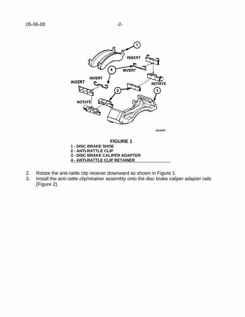
05-06-00 -2-
2. Rotate the anti-rattle clip retainer downward as shown in Figure 1.3. Install the anti-rattle clip/retainer assembly onto the disc brake caliper adapter rails
(Figure 2).
FIGURE 11 - DISC BRAKE SHOE2 - ANTI-RATTLE CLIP3 - DISC BRAKE CALIPER ADAPTER4 - ANTI-RATTLE CLIP RETAINER

-3- 05-06-00
4. Install inboard and outboard disc brake shoes onto the adapter (Figure 3).
POLICY: Information Only
FIGURE 21 - DISC BRAKE SHOE2 - ANTI-RATTLE CLIP/RETAINER ASSEMBLY3 - DISC BRAKE CALIPER ADAPTER
FIGURE 31 - DISC BRAKE SHOE2 - ANTI-RATTLE CLIP/RETAINER ASSEMBLY3 - DISC BRAKE CALIPER ADAPTER

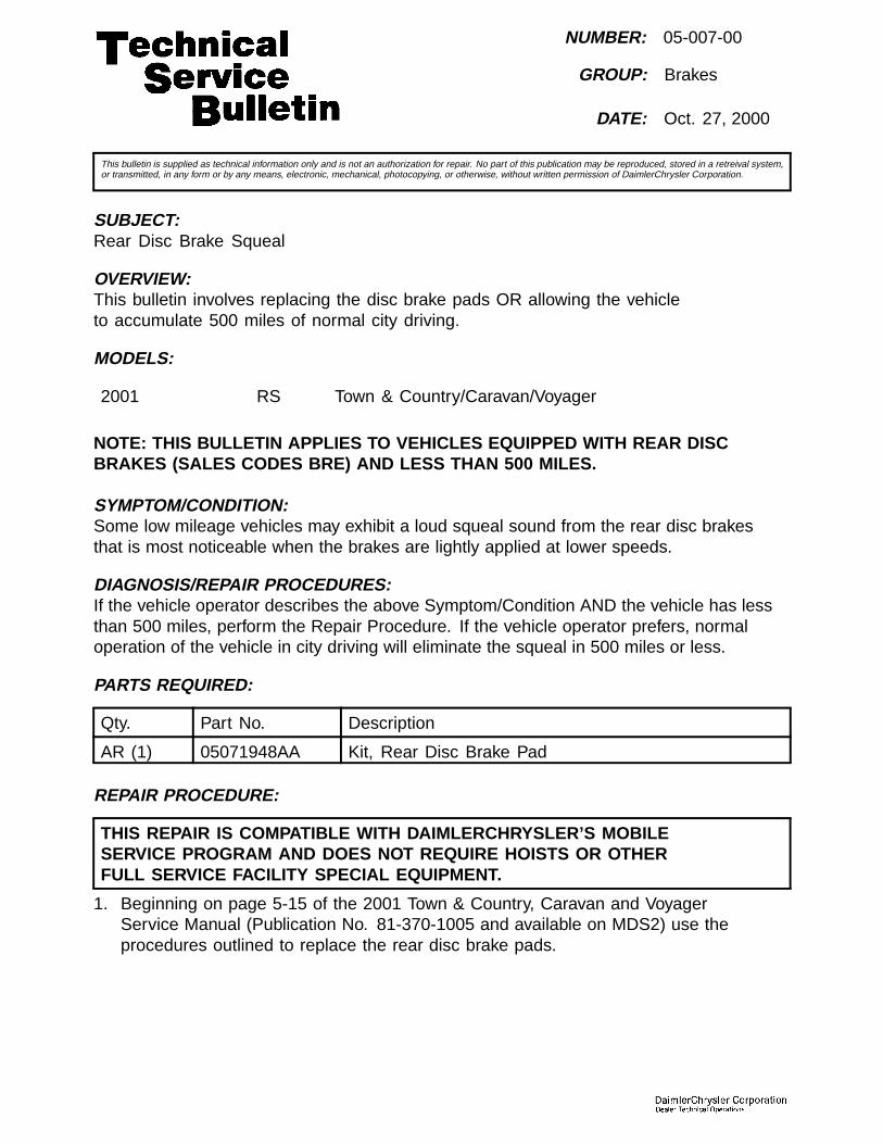
NUMBER: 05-007-00
GROUP: Brakes
DATE: Oct. 27, 2000
This bulletin is supplied as technical information only and is not an authorization for repair. No part of this publication may be reproduced, stored in a retreival system,or transmitted, in any form or by any means, electronic, mechanical, photocopying, or otherwise, without written permission of DaimlerChrysler Corporation.
SUBJECT:Rear Disc Brake Squeal
OVERVIEW:This bulletin involves replacing the disc brake pads OR allowing the vehicleto accumulate 500 miles of normal city driving.
MODELS:
2001 RS Town & Country/Caravan/Voyager
NOTE: THIS BULLETIN APPLIES TO VEHICLES EQUIPPED WITH REAR DISCBRAKES (SALES CODES BRE) AND LESS THAN 500 MILES.
SYMPTOM/CONDITION:Some low mileage vehicles may exhibit a loud squeal sound from the rear disc brakesthat is most noticeable when the brakes are lightly applied at lower speeds.
DIAGNOSIS/REPAIR PROCEDURES:If the vehicle operator describes the above Symptom/Condition AND the vehicle has lessthan 500 miles, perform the Repair Procedure. If the vehicle operator prefers, normaloperation of the vehicle in city driving will eliminate the squeal in 500 miles or less.
PARTS REQUIRED:
Qty. Part No. Description
AR (1) 05071948AA Kit, Rear Disc Brake Pad
REPAIR PROCEDURE:
THIS REPAIR IS COMPATIBLE WITH DAIMLERCHRYSLER’S MOBILESERVICE PROGRAM AND DOES NOT REQUIRE HOISTS OR OTHERFULL SERVICE FACILITY SPECIAL EQUIPMENT.
1. Beginning on page 5-15 of the 2001 Town & Country, Caravan and VoyagerService Manual (Publication No. 81-370-1005 and available on MDS2) use theprocedures outlined to replace the rear disc brake pads.
05-007-00 -2-
POLICY:Reimbursable within the provisions of the warranty.
TIME ALLOWANCE:
Labor Operation No: 05-70-22-94 0.5
FAILURE CODE:
P8 New Part
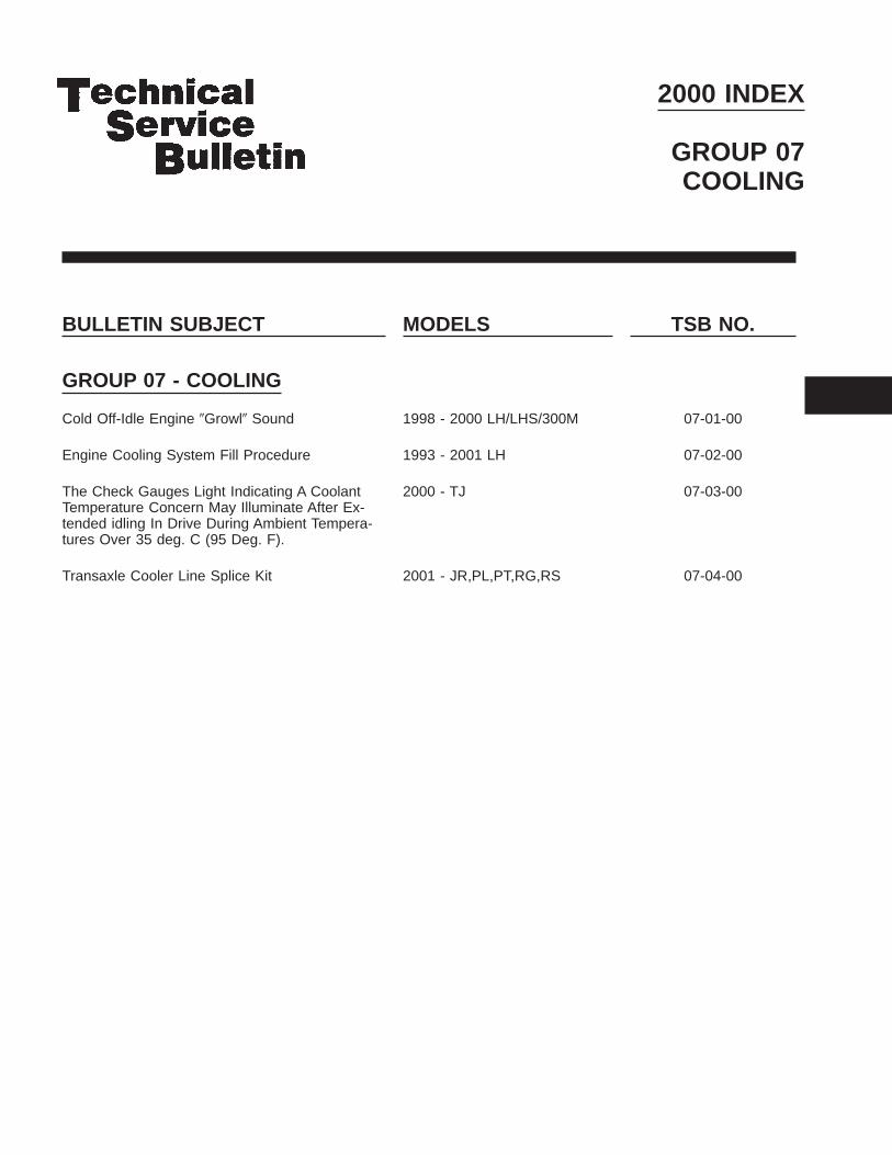
2000 INDEX
GROUP 07COOLING
BULLETIN SUBJECT MODELS TSB NO.
GROUP 07 - COOLING
Cold Off-Idle Engine 9Growl9 Sound 1998 - 2000 LH/LHS/300M 07-01-00
Engine Cooling System Fill Procedure 1993 - 2001 LH 07-02-00
The Check Gauges Light Indicating A CoolantTemperature Concern May Illuminate After Ex-tended idling In Drive During Ambient Tempera-tures Over 35 deg. C (95 Deg. F).
2000 - TJ 07-03-00
Transaxle Cooler Line Splice Kit 2001 - JR,PL,PT,RG,RS 07-04-00


Form TSB-003 Rev. 1.07
NUMBER: 07-01-00
GROUP: Cooling
DATE: Mar. 31, 2000
SUBJECT:Cold Off-Idle Engine “Growl” Sound
OVERVIEW:This bulletin involves raising the belt tension on the generator/power steering drive belt.
MODELS:1998 - 2000 (LH) Concorde/Interpid/LHS/300M
SYMPTOM/CONDITION:Low tone “growl” sound coming from engine following a cold start while in Drive or Reversewith engine RPM between 1000 and 1300 RPM.
DIAGNOSIS:Engine must be cooled to ambient temperature. Start engine; with one foot on the brakego to Drive or Reverse and gently raise engine speed to between 1000 and 1300 RPM. If“growl” sound can be heard coming from the generator/power steering drive belt check thebelt tension with Miller Special Tool 7198 or equivalent. If belt tension is below 120 lbs.,perform the Repair Procedure.
EQUIPMENT REQUIRED:# 7198 Miller Special Tool, Belt Tension Gauge
REPAIR PROCEDURE:1. Loosen the generator/power steering drive belt idler mounting nut 1/2 turn.
NOTE: ACCESS TO THE BELT AND ADJUSTING SCREW VARY WITH THEENGINE SIZE. REFER TO GROUP 7 OF THE 2000 CONCORDE/INTREPID/LHS/300M SERVICE MANUAL (PUBLICATION NO. 81-270-0040) FORACCESS POINTS.
2. Rotate the adjusting screw clockwise until belt tension is between 120 and 140 lbs.3. Tighten the idler mounting nut to 54 Nm (40 ft. lbs.).4. Verify belt tension.
POLICY: Reimbursable within the provisions of the warranty.
TIME ALLOWANCE:Labor Operation No: 07-20-15-96 Belt, Re-Tension - 2.7L Engine ...............0.2 Hrs.
07-20-15-97 Belt, Re-Tension - 3.2/3.5L Engine .........0.3 Hrs.
FAILURE CODE: 68 - Noisy
This bulletin is supplied as technical information only and is not an authorization for repair. No part of this publication may be reproduced, stored in a retrieval system, ortransmitted, in any form or by any means, electronic, mechanical, photocopying, recording, or otherwise, without written permission of DaimlerChrysler Corporation.

Form TSB-003 Rev. 1.08 February 3, 2000
NUMBER: 07-02-00
GROUP: Cooling
DATE: Jun. 16, 2000
SUBJECT:Engine Cooling System Fill Procedure
OVERVIEW:This bulletin provides the engine cooling system fill procedure.
MODELS:1993 - 2001 (LH) Concorde/Intrepid/LHS/New Yorker/Vision/300M
SYMPTOM/CONDITION:Some vehicles may exhibit engine overheating and/or coolant bottle failures after servicehas been performed on the engine cooling system. This may be caused by lack ofcomplete refilling of the system with coolant/antifreeze.
DIAGNOSIS:When refilling the engine cooling system after any service operation which required acomplete or partial draining of the engine coolant, the following Repair Procedure must beused to ensure a complete fill of the engine cooling system. This is a Repair Procedureclarification only. This bulletin does not apply when merely adding coolant because thecoolant level is visible but below the ΑCold Fill Line≅ (1993-1997 model years) or belowthe ΑMinimum Line≅ (1998 and later model years).
PARTS REQUIRED:AR 04267020AB Mopar Antifreeze/Coolant, 3 Year Formula, 1993 - 1997 M.Y.AR 05011764AB Mopar Antifreeze/Coolant, 5 Year/100,000 Mile, 1998 - 2001 M.Y.
EQUIPMENT REQUIRED:1 Miller Special Tool 8195, Cooling System Filling Aid
REPAIR PROCEDURE:
CAUTION: MAKE SURE ENGINE COOLING SYSTEM IS COOL BEFORE REMOVINGPRESSURE CAP OR ANY HOSE! SEVERE PERSONAL INJURY MAYRESULT FROM ESCAPING HOT COOLANT. THE COOLING SYSTEM ISPRESSURIZED WHEN HOT.
1. Obtain Cooling System filling aid (Special Tool 8195). The device looks like a funnelwhich attaches onto the filler neck (just as a regular pressure cap does) along with anattached hose clip
2. Attach filling aid to cooling system filler neck. Use the clip to pinch off the overflowhose attached to the fill neck. Attach a 1 1/2 to 2 meter (four to six foot) long 9 mm (1/4inch) ID clear hose to the bleed valve. Put the end of the hose into a clean container.This is to prevent coolant from spilling onto the accessory drive belts.
This bulletin is supplied as technical information only and is not an authorization for repair. No part of this publication may be reproduced, stored in a retrieval system, ortransmitted, in any form or by any means, electronic, mechanical, photocopying, recording, or otherwise, without written permission of DaimlerChrysler Corporation.

07-02-00 - 2 -
NOTE: IT IS IMPERATIVE THAT THE COOLING SYSTEM AIR BLEED VALVE BEOPENED BEFORE ANY COOLANT IS ADDED TO THE COOLING SYSTEM.FAILURE TO OPEN THE BLEED VALVE FIRST WILL RESULT IN ANINCOMPLETE FILL OF THE SYSTEM.
3. Open the cooling system bleed valve:1998 model years and later
• 2.7 Liter Engines: Located on the water outlet connector at the front of theengine.
• 3.2/3.5 Liter engines: Located on the lower intake manifold, left of centerunder the upper intake manifold.
1993-1997 model years• 3.5 Liter engine: Located on the thermostat housing.• 3.3 Liter engine: Located on the thermostat housing
4. Pour a 50/50 mixture of coolant and water into the filling aid / funnel. Mix the coolantconcentrate with distilled, deionized, or reverse-osmosis purified water (unless coolantis supplied pre-mixed with water).
5. Slowly fill the cooling system through the filling aid. Watch the hose connected to thebleed valve! When a steady stream of coolant comes out of the hose, close the bleedvalve and continue filling to the top of the filling aid.
6. 1993-1997 model years: Put a small, clean reservoir (approximately 16 ounce or 1/2liter capacity) below the end of the overflow hose.
7. Remove the clip from the overflow hose. Any excess coolant in the filling aid will nowdrain into the overflow section of the coolant bottle or into the small reservoir.
8. 1993 - 1997 model years: Remove the reservoir and recycle the excess coolant.9. Remove the filling aid from the fill neck. Ensure that the bottom seal of the cap and the
fill neck are free of debris and replace the pressure cap on the coolant bottle.
IMPORTANT: The 1998 and later model year coolant bottle has two chambers. Coolantwill normally only be in the inboard (smaller) of the two. The outboardchamber is only to recover coolant in the event of an overheat and shouldnormally be empty (except for the coolant drained from the filling aid. Thiscoolant will be drawn back into the pressurized side of the cooling systemover time).
NOTE: COOLING SYSTEM FILL PROCEDURES ARE CRITICAL TO OVERALLCOOLING SYSTEM PERFORMANCE.
POLICY: Information Only

Form TSB-003 Rev. 1.08 February 3, 2000
NUMBER: 07-03-00
GROUP: Cooling
DATE: Aug. 4, 2000
SUBJECT:The Check Gauges light indicating a coolant temperature concern may illuminate afterextended idling in drive during ambient temperatures over 35 deg. C (95 deg. F).
OVERVIEW:This bulletin involves selectively erasing and reprogramming the JTEC Powertrain ControlModule (PCM) with new software (calibration change 00Cal15A).
MODELS:2000 (TJ) Wrangler
NOTE: THIS BULLETIN APPLIES TO VEHICLES EQUIPPED WITH A 4.0L ENGINEAND AUTOMATIC TRANSMISSION.
SYMPTOM/CONDITION:Engine coolant temperatures may rise high enough to cause the Check Gauges light toilluminate, indicating excessive coolant temperature. This condition is likely to happenafter extended periods of idling, with the transmission in Drive, the air conditioning on, andwith ambient temperatures above 35 deg. C (95 deg. F).
If the transmission is placed in the Park or Neutral positions, or if the vehicle is driven, thenthe engine temperatures will decrease.
DIAGNOSIS:1. Verify that the cooling system is in good working condition.2. Verify that the engine coolant mixture contains the proper amount of antifreeze.3. If a customer indicates that their vehicle exhibits this condition in high ambient
temperatures, perform the Repair Procedure.
NOTE: REFER THE CUSTOMER TO THE 2000 JEEP WRANGLER OWNER’SMANUAL (81-326-0050). IT IS IMPORTANT THAT THE PROPERPROCEDURES ARE FOLLOWED TO PREVENT AN ENGINE OVERHEATCONDITION. REFER TO THE SECTION IN THE MANUAL TITLED, IF YOURENGINE OVERHEATS (PAGE 158), FOR ADDITIONAL ASSISTANCE.
NOTE: WHENEVER A POWERTRAIN CONTROL MODULE (PCM) IS REPLACEDDUE TO FAILURE, THE SOFTWARE OF THE REPLACEMENT CONTROLLERMUST BE VERIFIED FOR THE LATEST REVISION LEVEL. USE THE FLASHPROCEDURE TO UPDATE REPLACED CONTROLLERS AS NECESSARY.
PARTS REQUIRED:1 04669020 Label, Authorized Software Update1 04275086 Label, Authorized Modification
This bulletin is supplied as technical information only and is not an authorization for repair. No part of this publication may be reproduced, stored in a retrieval system, ortransmitted, in any form or by any means, electronic, mechanical, photocopying, recording, or otherwise, without written permission of DaimlerChrysler Corporation.

07-03-00 -2-
EQUIPMENT REQUIRED:1 CH6000 Scan Tool (DRB III7)1 CH7035 General Purpose Interface Bus Cable (GPIB)1 CH7000/7001 J1962 Cable1 MDS2
NOTE: THE MDS2 AND DRB III77 ARE REQUIRED TO PERFORM PART OF THISREPAIR. WHEN USING THE MDS2 AND THE DRB III77, THE SYSTEM MUSTBE OPERATING AT CIS CD 2064 OR HIGHER.
REPAIR PROCEDURE:1. Log onto the MDS2 system.2. Connect the MDS2 and DRB III7 to the vehicle and switch the ignition key to “ON”.3. Use the arrow keys and select #2 CONNECT TO MDS2 on the DRB III7 MAIN MENU
SCREEN.4. Use the arrow keys and select #2 RUN MDS2 APPLICATION on the DRB III7 MAIN
MENU SCREEN.
NOTE: ONCE MDS2, DRB III77, AND VEHICLE COMMUNICATION HAS BEENESTABLISHED, THE “CANNOT READ VIN FROM DRB III77” MESSAGE (ONTHE MDS2) WILL BE REPLACED BY THE VEHICLE VIN. PRESS THE “OK”BUTTON ON THE MDS2 TO REQUEST A MDS2 SESSION FOR THEVEHICLE VIN INDICATED. PRESS THE “OK” BUTTON WHEN ASKED TOBEGIN SESSION.
5. Select the FLASH tab on the MDS2.
6. Select READ PART NUMBERS FROM VEHICLE and click SHOW UPDATES on theMDS2. Press the “OK” button.
NOTE: IN ABOVE STEPS #5 AND/OR #6, A MESSAGE MAY APPEAR THATINDICATES NO UPDATES ARE AVAILABLE. IF THIS OCCURS, MAKESURE YOUR DIAGNOSTIC EQUIPMENT IS OPERATING AT THE LATESTSOFTWARE LEVEL AS LISTED EARLIER IN THIS BULLETIN. IF THELATEST SOFTWARE IS INSTALLED, AND NO UPDATES ARE AVAILABLE,ANOTHER VEHICLE CONDITION EXISTS THAT WILL REQUIRE FURTHERINVESTIGATION.
7. Select the new software part number with the light pen and click UPDATECONTROLLER SOFTWARE.
8. The MDS2 and DRB III7 will prompt for any operator action needed during theremainder of the reprogramming process.

-3- 07-03-00
NOTE: DUE TO THE PCM REPROGRAMMING PROCEDURE, A DTC MAY BE SETIN OTHER MODULES (EATX, BCM, MIC, SKIM) WITHIN THE VEHICLE IF SOEQUIPPED. SOME DTC’S MAY CAUSE THE MIL TO ILLUMINATE. ALLDTC’S RELATE TO A LOSS OF COMMUNICATIONS WITH THE MODULETHAT IS BEING REPROGRAMMED. CHECK ALL MODULES, RECORD THEFAULTS, AND ERASE THESE FAULTS PRIOR TO RETURNING THEVEHICLE TO THE CUSTOMER. ERASE ANY FAULTS IN THE PCM ONLYAFTER ALL OTHER MODULES HAVE HAD THEIR FAULTS ERASED.
NOTE: THE FOLLOWING STEPS ARE REQUIRED BY LAW.
9. Type the necessary information on the “Authorized Software Update Label” p/n04669020 (Figure 1). Attach the label to the JTEC PCM and cover the label with the clearplastic overlay.
FIGURE 1______________________
10. Type the necessary information on the “Authorized Modification Label” p/n 04275086and attach the label near the VECI label (Figure 2).
1
2 3 4
1 – CONTROL MODULE PART NUMBER (INSERT NEW P/N HERE)2 - CHANGE AUTHORITY: TSB XX-XX-XX3 - DEALER CODE: XXXXX4 - DATE: XX-XX-XX
FIGURE 2

07-03-00 -4-
POLICY: Reimbursable within the provisions of the warranty.
TIME ALLOWANCE:Labor Operation No:
08-19-44-95 (Reprogram PCM) ……………………………………………...0.5 Hrs.
FAILURE CODE: FM – Flash Module
NUMBER: 07-004-00
GROUP: Cooling
DATE: Jan. 12, 2001
This bulletin is supplied as technical information only and is not an authorization for repair. No part of this publication may be reproduced, stored in a retreival system,or transmitted, in any form or by any means, electronic, mechanical, photocopying, or otherwise, without written permission of DaimlerChrysler Corporation.
SUBJECT:Transaxle Cooler Line Splice Kit
MODELS:
2001 (JR) Sebring/Stratus Sedan/Sebring Convertible
2001 (PL) Neon
2001 (PT) PT Cruiser
2001 (RG) Chrysler Voyager (International Market)
2001 (RS) Town & Country/Caravan/Voyager
DISCUSSION:A connector kit p/n 05016918AA has been released to make transaxle cooler lineservice easier. This kit should be installed whenever service is performed thatrequires cooler line removal from the transaxle. This will make the lines easy toremove and install should service be required at a later time. An instruction sheetis included with each kit that details installation procedures.
PARTS REQUIRED:
Qty. Part No. Description
1 05016918AA Kit, Transmission Cooler Line Connector
POLICY:Information Only


2000 INDEX
GROUP 08ELECTRICAL
BULLETIN SUBJECT MODELS TSB NO.
GROUP 08 - ELECTRICALNo Start (Engine Will Not Crank) Due To A BlownStarter Relay Circuit Fuse
2000 AB, 2000 - 2001 AB,BR/BE
08-01-00 Rev. A
Headlamp Welt Service 1998 - 2000 LH/LHS/300M 08-02-00
Erratic Operation Of The Power Door Locks, Re-mote Keyless Entry System, Power Windows OrPower Mirrors
1999 WJ 08-03-00
Light Bulb Applications And Replacement Infor-mation
2001 PT 08-04-00
Intermittent Operation Of The Instrument Cluster 1999 - AB,AN,BR/BE,DN 08-05-00

BULLETIN SUBJECT MODELS TSB NO.
Wire Splice Repairs 1988 - BB 1989 - AA,AB,AC,AD,AG, AH,AJ,AK,AL,AM,AN,AP,AS,B2,B7,MJ,XJ,YJ1990 - AA,AB,AC,AD,AG,AJ,AK, AL,AN,AP,AS,AY,BB,BD,B2,B7,MJ1991 - AA,AB,AC,AD,AG,AJ,AN,AP,AS,AY,BB,BD,B2,B7,MJ,XJ,YJ1992 - AA,AB,AC,AD,AG,AJ,AN,AP,AS,AY,BB,BD,B2,B3,B7,B8,ES,MJ,XJ,YJ1993 - AA,AB,AC,AD,AG,AJ,AN,AP,AS,AY,BD,B3,B7,B8,B9,ES,LH,XJ,YJ,ZJ1994 - AA,AB,AG,AJ,AN,AP,AS,BD,BR/BE,B3,B7,B8,B9,ES,LH,XJ,YJ,ZJ F1995 - AA,AB,AJ,AN,AS,BR/BE,B3,B7,B8,ES,FJ,JA,LH,PL,XJ,YJ,ZJ1996 - AB,AN,BR/BE,FJ,GS,JA,JX,LH,NS,PL,SR,XJ,ZG,ZJ1997 - AB,AN,BR/BE,FJ,GS,JA,JX,LH,NS,PL, ,PR,SR,TJ,XJ,ZG,ZJ1998 - AB,AN,BR/BE,DN,FJ,GS,JA,JX,LH,NS,PL,PR,SR,TJ,XJ,ZG,ZJ1999 - AB,AN,BR/BE,DN,FJ,GS,JA,JX,LH,NS,PL,PR,SR,TJ,WJ,XJ2000 - AB,AN,BR/BE,DN,FJ,GS,JA,JX,LH,NS,PL,PR,SR,TJ,WJ,XJ,2001 AB,AN,BR/BE
08-06-00 Rev. A
Erroneous MIL Due To DTC P0443 (Purge Ckt)And/Or A Possible Key-Off Battery Draw
1999 DN 08-07-00
Inoperative Or Intermittent Remote Keyless Entry(RKE) Transmitter
1998 - 2000 LH1999 - 2000 AN,DN,BR/BE,XJ,WJ,AB 2000 - PL
08-08-00
Headlamp Service Change 2000 Concorde/LHS 300M 08-09-00
Dead Battery And/Or Ignition Operated ElectricalAccessories Function With Ignition Off
2000 - AN, 1998 - 2000 DN 08-10-00

BULLETIN SUBJECT MODELS TSB NO.
Recordable Compact Discs Used In AutomotiveCD Players
1989 - 2000 AB1989 - 2000 AN1994 - 2000 BR/BE1998 - 2000 DN1995 - 1999 FJ1995 - 1999 JA1993 - 1999 LH1996 - 2000 NS1995 - 2000 PL1997 - 1999 PR1996 - 1999 SR1997 - 2000 TJ1999 - 2000 WJ1997 - 2000 XJ1993 - 1998 ZJ
08-11-00
Instrument Cluster Gauge Pointers On WrongSide Of Pointer Stops
2000 - PL,JA,JX,TJ,XJ 08-12-00
Lack Of Base Sound Coming From Rear Speak-ers
2000 AN 08-13-00
Fuel Gauge Does Not Register Full 2001 PT 08-14-00
Intermittent Instrument Panel SpeakerOperation/Static
1999 - 2000 NS,GS 08-15-00
Front Door Speaker Buzz 1994 - 2000 BR/BE 08-16-00
Intermittent Speaker Operation/Static 1999 - 2000 BR/BE 08-17-00
Radio Interference To/From Two-Way Radio Re-ceivers
1997 - 2000 AN1998 - 2001 BR/BE
08-18-00
Garage Door Opener Transmitter Range 1998 - 2000 LH/LHS/300M 08-19-00
Horn Inoperative Or Sound Is Weak Or Muted 2000 - PL 08-20-00
Antenna Mast Installation 2000 - 2001 PL 08-21-00
4.7L Camshaft Position Sensor Contacts ToneWheel
2000 - AN, DN, WJ 08-22-00 Rev. A
Plastic Boot To Protect The Electrical HarnessB+ End Terminal At The Generator
1998 - 2001 BR, BE 08-23-00
Engine Cranks But Does Not Start Or Starts AndStalls
1998 - 2001 AB,BR/BE1997 - 2000 AN1998 - 2000 DN
08-24-00
Remote Keyless entry (RKE) Unlock Sequence -All Doors Unlock On First Button Press
2001 - DN 08-25-00
Central Timer Module Electrically 9Locks-Up9 2000 - AB,AN,BR/BE,DN2001 - AB,BR/BE
08-26-00
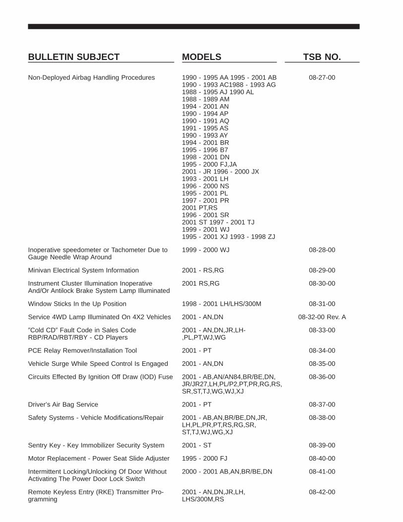
BULLETIN SUBJECT MODELS TSB NO.
Non-Deployed Airbag Handling Procedures 1990 - 1995 AA 1995 - 2001 AB1990 - 1993 AC1988 - 1993 AG1988 - 1995 AJ 1990 AL1988 - 1989 AM1994 - 2001 AN1990 - 1994 AP1990 - 1991 AQ1991 - 1995 AS1990 - 1993 AY1994 - 2001 BR1995 - 1996 B71998 - 2001 DN1995 - 2000 FJ,JA2001 - JR 1996 - 2000 JX1993 - 2001 LH1996 - 2000 NS1995 - 2001 PL1997 - 2001 PR2001 PT,RS1996 - 2001 SR2001 ST 1997 - 2001 TJ1999 - 2001 WJ1995 - 2001 XJ 1993 - 1998 ZJ
08-27-00
Inoperative speedometer or Tachometer Due toGauge Needle Wrap Around
1999 - 2000 WJ 08-28-00
Minivan Electrical System Information 2001 - RS,RG 08-29-00
Instrument Cluster Illumination InoperativeAnd/Or Antilock Brake System Lamp Illuminated
2001 RS,RG 08-30-00
Window Sticks In the Up Position 1998 - 2001 LH/LHS/300M 08-31-00
Service 4WD Lamp Illuminated On 4X2 Vehicles 2001 - AN,DN 08-32-00 Rev. A
9Cold CD9 Fault Code in Sales CodeRBP/RAD/RBT/RBY - CD Players
2001 - AN,DN,JR,LH-,PL,PT,WJ,WG
08-33-00
PCE Relay Remover/Installation Tool 2001 - PT 08-34-00
Vehicle Surge While Speed Control Is Engaged 2001 - AN,DN 08-35-00
Circuits Effected By Ignition Off Draw (IOD) Fuse 2001 - AB,AN/AN84,BR/BE,DN,JR/JR27,LH,PL/P2,PT,PR,RG,RS,SR,ST,TJ,WG,WJ,XJ
08-36-00
Driver’s Air Bag Service 2001 - PT 08-37-00
Safety Systems - Vehicle Modifications/Repair 2001 - AB,AN,BR/BE,DN,JR,LH,PL,PR,PT,RS,RG,SR,ST,TJ,WJ,WG,XJ
08-38-00
Sentry Key - Key Immobilizer Security System 2001 - ST 08-39-00
Motor Replacement - Power Seat Slide Adjuster 1995 - 2000 FJ 08-40-00
Intermittent Locking/Unlocking Of Door WithoutActivating The Power Door Lock Switch
2000 - 2001 AB,AN,BR/BE,DN 08-41-00
Remote Keyless Entry (RKE) Transmitter Pro-gramming
2001 - AN,DN,JR,LH,LHS/300M,RS
08-42-00

NUMBER: 08-01-00 Rev. A
GROUP: Electrical
EFFECTIVE DATE: June 30, 2000
THIS BULLETIN SUPERSEDES TECHNICAL SERVICE BULLETIN 08-01-00, DATEDJAN. 21, 2000, WHICH SHOULD BE REMOVED FROM YOUR FILES. THIS IS ACOMPLETE REVISION AND NO ASTERISKS HAVE BEEN USED TO HIGHLIGHTREVISIONS.
SUBJECT:No Start (Engine Will Not Crank) Due To A Blown Starter Relay Circuit Fuse
OVERVIEW:This bulletin involves installing a starter solenoid jumper relay/harness assembly and anew fuse.
MODELS:2000 (AB) Ram Van/Wagon2000 - 2001 (BR/BE) Ram Truck
NOTE: THIS BULLETIN APPLIES TO RAM TRUCKS AND RAM VANS/WAGONSBUILT BEFORE THE FOLLOWING DATES:RAM VANS/WAGONS• PILLETTE ROAD ASSEMBLY PLANT - ALL EXCEPT CNG VEHICLES -
JANUARY 18, 2000 (MDH 0118XX). CNG VEHICLES - JANUARY 25, 2000(MDH 0125XX).
RAM TRUCKS• ST. .LOUIS ASSEMBLY PLANT (11TH VIN POSITION = “J”) - JANUARY
25, 2000 (MDH 0125XX)• WARREN TRUCK ASSEMBLY PLANT (11TH VIN POSITION = “S”) -
FEBRUARY 2, 2000 (MDH 0202XX).• SALTILLO TRUCK ASSEMBLY PLANT (11TH VIN POSITION = “G”) -
FEBRUARY 7, 2000 (MDH 0207XX).• LAGO ALBERTO ASSEMBLY PLANT (11TH VIN POSITION = “M”) -
FEBRUARY 14, 2000 (MDH 0214XX).
SYMPTOM/CONDITION:The vehicle will not start (engine will not crank) due to a blown starter relay circuit fuse.
DIAGNOSIS:Inspect for a blown starter relay circuit fuse. The starter relay circuit fuse is located in thefuse block on Ram Van/Wagons and is fuse number 17. On Ram Trucks, the starter relayfuse is located in the Power Distribution Center (PDC) and is fuse “D.” If the fuse is blown,inspect the starter relay circuit for any electrical shorts to ground. Refer to the appropriateService Manual, Group 8W-21 “Starting System Wiring Diagrams” for circuit identification,components, and their locations. If there are no apparent electrical shorts to ground in thestarter relay circuit, perform the Repair Procedure.
This bulletin is supplied as technical information only and is not an authorization for repair. No part of this publication may be reproduced, stored in a retrieval system, ortransmitted, in any form or by any means, electronic, mechanical, photocopying, recording, or otherwise, without written permission of DaimlerChrysler Corporation.
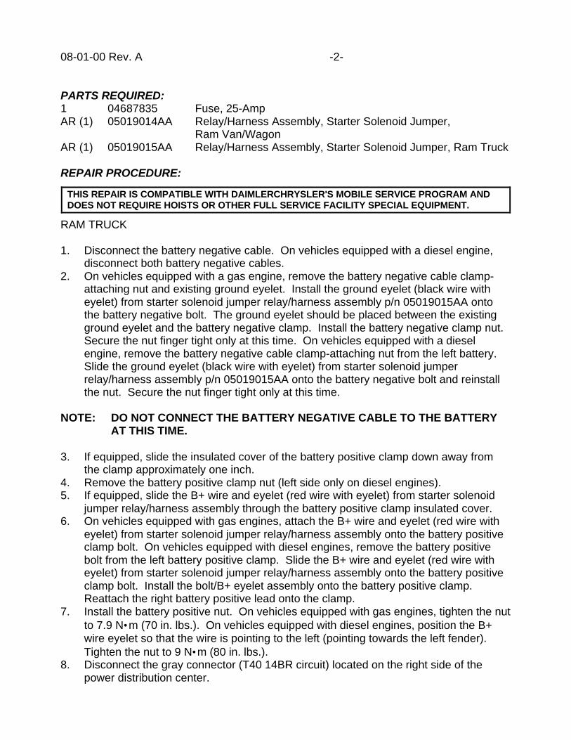
08-01-00 Rev. A -2-
PARTS REQUIRED:1 04687835 Fuse, 25-AmpAR (1) 05019014AA Relay/Harness Assembly, Starter Solenoid Jumper,
Ram Van/WagonAR (1) 05019015AA Relay/Harness Assembly, Starter Solenoid Jumper, Ram Truck
REPAIR PROCEDURE:
RAM TRUCK
1. Disconnect the battery negative cable. On vehicles equipped with a diesel engine,disconnect both battery negative cables.
2. On vehicles equipped with a gas engine, remove the battery negative cable clamp-attaching nut and existing ground eyelet. Install the ground eyelet (black wire witheyelet) from starter solenoid jumper relay/harness assembly p/n 05019015AA ontothe battery negative bolt. The ground eyelet should be placed between the existingground eyelet and the battery negative clamp. Install the battery negative clamp nut.Secure the nut finger tight only at this time. On vehicles equipped with a dieselengine, remove the battery negative cable clamp-attaching nut from the left battery.Slide the ground eyelet (black wire with eyelet) from starter solenoid jumperrelay/harness assembly p/n 05019015AA onto the battery negative bolt and reinstallthe nut. Secure the nut finger tight only at this time.
NOTE: DO NOT CONNECT THE BATTERY NEGATIVE CABLE TO THE BATTERYAT THIS TIME.
3. If equipped, slide the insulated cover of the battery positive clamp down away fromthe clamp approximately one inch.
4. Remove the battery positive clamp nut (left side only on diesel engines).5. If equipped, slide the B+ wire and eyelet (red wire with eyelet) from starter solenoid
jumper relay/harness assembly through the battery positive clamp insulated cover.6. On vehicles equipped with gas engines, attach the B+ wire and eyelet (red wire with
eyelet) from starter solenoid jumper relay/harness assembly onto the battery positiveclamp bolt. On vehicles equipped with diesel engines, remove the battery positivebolt from the left battery positive clamp. Slide the B+ wire and eyelet (red wire witheyelet) from starter solenoid jumper relay/harness assembly onto the battery positiveclamp bolt. Install the bolt/B+ eyelet assembly onto the battery positive clamp.Reattach the right battery positive lead onto the clamp.
7. Install the battery positive nut. On vehicles equipped with gas engines, tighten the nutto 7.9 N•m (70 in. lbs.). On vehicles equipped with diesel engines, position the B+wire eyelet so that the wire is pointing to the left (pointing towards the left fender).Tighten the nut to 9 N•m (80 in. lbs.).
8. Disconnect the gray connector (T40 14BR circuit) located on the right side of thepower distribution center.
THIS REPAIR IS COMPATIBLE WITH DAIMLERCHRYSLER'S MOBILE SERVICE PROGRAM ANDDOES NOT REQUIRE HOISTS OR OTHER FULL SERVICE FACILITY SPECIAL EQUIPMENT.

-3- 08-01-00 Rev. A
9. Connect the two remaining leads of the starter solenoid jumper relay/harnessassembly to the disconnected gray connector.
10. Secure the starter solenoid jumper relay/harness assembly to the battery positivecable as shown in Figure 1. Secure the top of the relay by placing a tie-strap throughthe hole of the relay bracket and wrap the tie-strap around the battery positive cable.Secure the middle of the relay by placing at least four wraps of electrical tape aroundthe relay and the battery positive cable. Secure the wiring harness of the relayassembly by placing at least two wraps of electrical tape around the harness andbattery positive cable.
11. Remove the blown fuse from the power distribution center and install a 25-amp fusep/n 04687835.
12. Connect the battery negative cable(s). On vehicles equipped with gas engines,tighten the nut to 7.9 N•m (70 in. lbs.). On vehicles equipped with diesel engines,position the ground eyelet so that the wire is pointing to the left (pointing towards theleft fender). Tighten the nut to 9 N•m (80 in. lbs.). Reset the clock.
13. Verify the repair by ensuring that the engine starter circuit operates.
FIGURE 1 - GAS ENGINE EQUIPPEDVEHICLES SHOWN
1 - TIE STRAP TOP OF RELAY TO BATTERY POSITIVE HARNESS2 - SECURE THE MIDDLE OF THE RELAY TO THE BATTERY POSITIVE HARNESS USING ELECTRICAL TAPE3 - STARTER SOLENOID JUMPER RELAY4 - STARTER SOLENOID JUMPER RELAY HARNESS GROUND5 - SECURE THE RELAY HARNESS TO THE BATTERY POSITIVE HARNESS USING ELECTRICAL TAPE6 - STARTER SOLENOID CONNECTOR (T40 14BR)7 - STARTER SOLENOID CONNECTOR (T40 14BR)

08-01-00 Rev. A -4-
NOTE: A SUPPLEMENTAL WIRE SCHEMATIC FOR PAGE 8W-21-2 OF THE 2000RAM TRUCK SERVICE MANUAL (PUBLICATION NO. 81-370-0008) ISATTACHED TO THIS TECHNICAL SERVICE BULLETIN FOR YOURREFERENCE.
RAM VAN/WAGON
1. Disconnect the battery negative cable.2. Remove the battery negative cable clamp attaching nut and bolt. Slide the ground
eyelet (black wire with eyelet) from starter solenoid jumper relay/harness assemblyp/n 05019014AA onto the battery negative bolt. Install the battery negativebolt/ground eyelet assembly onto the battery negative clamp.
3. Install the battery negative clamp nut. Secure the nut finger tight only at this time.
NOTE: DO NOT CONNECT THE BATTERY NEGATIVE CABLE TO THE BATTERYAT THIS TIME.
4. Remove the battery positive clamp nut.5. Attach the B+ wire eyelet (red/gray wire with eyelet) from starter solenoid jumper
relay/harness assembly onto the battery positive clamp bolt. Place the B+ wire eyeletbetween the existing eyelet (if equipped) and the battery positive clamp.
6. Install the battery positive nut. Tighten the nut to 7.9 N•m (70 in. lbs.).7. Disconnect the gray connector (T40 14BR circuit) located to the right of the battery
above the power distribution center.8. Connect the two remaining leads of the starter solenoid jumper relay/harness
assembly to the disconnected gray connector.9. Secure the starter solenoid jumper relay/harness assembly to the headlamp and dash
harness as shown in Figure 2. Secure the top of the relay by placing a tie-strapthrough the hole of the relay bracket and wrap the tie-strap around the headlamp anddash harness. Secure the middle of the relay by placing at least four wraps ofelectrical tape around the relay and the headlamp and dash harness. Secure thewiring harness of the relay assembly by placing at least two wraps of electrical tapearound the jumper harness and headlamp and dash harness.
10. Remove the blown fuse from the fuse block (cavity 17) and install a 25-amp fuse p/n04687835.
11. Connect the battery negative cable. Tighten the nut to 7.9 N•m (70 in. lbs.). Resetthe clock.
12. Verify the repair by ensuring that the engine starter circuit operates.
NOTE: A SUPPLEMENTAL WIRE SCHEMATIC FOR PAGE 8W-21-2 OF THE 2000RAM VAN SERVICE MANUAL (PUBLICATION NO. 81-370-0007) ISATTACHED TO THIS TECHNICAL SERVICE BULLETIN FOR YOURREFERENCE.
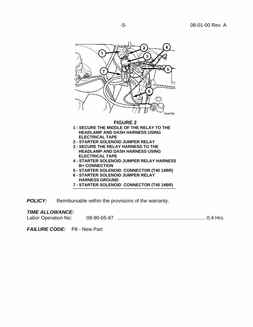
-5- 08-01-00 Rev. A
POLICY: Reimbursable within the provisions of the warranty.
TIME ALLOWANCE:Labor Operation No: 08-90-65-97 ................................................................0.4 Hrs.
FAILURE CODE: P8 - New Part
FIGURE 21 - SECURE THE MIDDLE OF THE RELAY TO THE HEADLAMP AND DASH HARNESS USING ELECTRICAL TAPE2 - STARTER SOLENOID JUMPER RELAY3 - SECURE THE RELAY HARNESS TO THE HEADLAMP AND DASH HARNESS USING ELECTRICAL TAPE4 - STARTER SOLENOID JUMPER RELAY HARNESS B+ CONNECTION5 - STARTER SOLENOID CONNECTOR (T40 14BR)6 - STARTER SOLENOID JUMPER RELAY HARNESS GROUND7 - STARTER SOLENOID CONNECTOR (T40 14BR)

08-01-00 Rev. A -6-
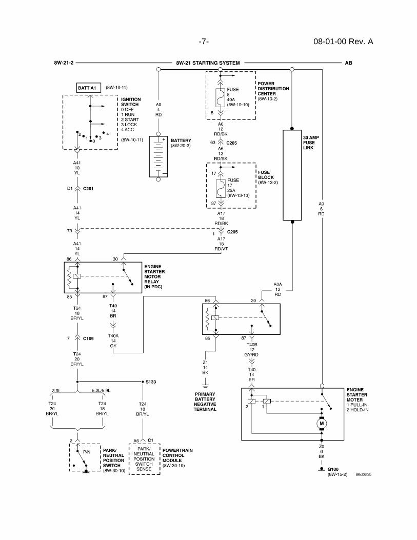
-7- 08-01-00 Rev. A


Form TSB-003 Rev. 1.07
NUMBER: 08-02-00
GROUP: Electrical
DATE: Feb. 11, 2000
THIS BULLETIN SUPERSEDES TECHNICAL SERVICE BULLETIN 08-05-99 DATEDMARCH 3, 1999 WHICH SHOULD BE REMOVED FROM YOUR FILES. ALLREVISIONS ARE HIGHLIGHTED WITH **ASTERISKS** AND INCLUDE ANADDITIONAL MODEL YEAR, MODIFIED PROCEDURE, AND A NOTE ABOUTSERVICE PARTS.
SUBJECT:Headlamp Welt Service
OVERVIEW:This bulletin involves replacing the headlamp welt(s) with revised parts.
MODELS:1998 - **2000** (LH) Concorde/LHS/300M
SYMPTOM/CONDITION:The headlamp-to-fender, hood, and fascia welt may become cut torn or otherwisedamaged. To correct this condition it is no longer necessary to replace the headlampassembly; the welt is now available as a serviceable part.
DIAGNOSIS:Inspect headlamp welt for damage. Inspect mating fender/hood/fascia for cause ofdamage, repair as necessary. To replace welt perform the Repair Procedure.
PARTS REQUIRED:AR(2) 05014909AA Welt, Headlamp
**NOTE: THE HEADLAMP WELT INSTALLED AT THE ASSEMBLY PLANTCHANGED TO A MOLDED DESIGN IN JANUARY 2000 TO AID INPRODUCTION INSTALLATION. THE WELT LISTED ABOVE SHOULD BEUSED FOR ALL SERVICE REPLACEMENT NEEDS REGARDLESS OFTHE STYLE WELT THE VEHICLE IS EQUIPPED WITH.**
REPAIR PROCEDURE:
1. Remove the headlamp housing assembly as described on page 8L-18 of the 2000Concorde/Intrepid/LHS/300M Service Manual (Publication No. 81-270-0040).
2. Before removing the existing welt from the headlamp, mark the location of the welt onthe lens with a grease pencil or masking tape. This is especially important in the fenderand inboard fascia areas on the Concorde and LHS. Also note any areas where thewelt material is "doubled-up." Depending on the fit to the vehicle being repaired, it maybe necessary to duplicate this procedure.
This bulletin is supplied as technical information only and is not an authorization for repair. No part of this publication may be reproduced, stored in a retrieval system, ortransmitted, in any form or by any means, electronic, mechanical, photocopying, recording, or otherwise, without written permission of DaimlerChrysler Corporation.
THIS REPAIR IS COMPATIBLE WITH DAIMLERCHRYSLER'S MOBILE SERVICE PROGRAM ANDDOES NOT REQUIRE HOISTS OR OTHER FULL SERVICE FACILITY SPECIAL EQUIPMENT.

08-02-00 - 2 -
**3. Concorde/LHS/300M built prior to January 2000 (Extruded Welt)Carefully remove the old welt material from the lamp by pulling it away from the lens.Do not use knives or blades to cut it, as you may damage the coating on the lens. Onthe Concorde and LHS it is best to start at the overlap joint on the bottom of the lamp,and on the 300M, start at the inboard edge. Note how the outboard end of the welt onthe 300M is tucked under the lens clip. The lens clip can be removed with a smallscrewdriver. Save the clip for reinstallation (if necessary, a clip may be relocated fromanother location).Concorde/LHS built starting January 2000 (Molded Welt)Remove the three screws securing the welt to the top of the lamp and unbuckle thewelt from the circumference of the lens. Fill the three screw bosses/holes with siliconesealer, Mopar p/n 05010884AA, or equivalent**
4. Make sure the old welt adhesive residue is removed from the lamp. If necessary, acloth LIGHTLY DAMPENED with isopropyl alcohol or Mopar Super Clean, p/n04886330AA, may be used to remove the residue and prepare the surface for the newwelt.
NOTE: IT IS IMPORTANT THAT NO EXCESS SOLVENT RUNS ON THE LENS OR THEBOND JOINT OF THE HOUSING, AS THIS WILL CAUSE THE LENS TOSTRESS CRACK. DO NOT APPLY SOLVENT DIRECTLY TO THE LENS.
5. Carefully peel away about 1 foot of the plastic strip that covers the adhesive on the newwelt. Do not remove it all at once.
6. Begin to apply the welt material to the lamp by lightly pressing the adhesive strip to thelens in the same position as the old welt. On Concorde and LHS, the seam should beat the bottom of the lamp, while on the 300M it is best to start the welt application onthe inboard upper corner of the lens. DO NOT STRETCH THE WELT MATERIALWHEN APPLYING. Peel away the plastic strip on the adhesive as required while youwork your way around the perimeter of the lamp. Follow the guide marks that youmade in step 2. If the welt appears to be crooked, reposition it slightly before you pressit down too firmly. When you get to the beginning of the welt on the Concorde andLHS, leave enough welt material to overlap the ends at least 1/2 inch, and trim it with asharp knife or scissors. Tuck the end into the open section of the welt where youoriginally began the application. On the 300M, trim the end so that you have at least 1inch. extending beyond the clip that you removed in step 3. Replace the clip so that itholds the welt in the correct position.
7. With the welt correctly positioned, press down firmly around the perimeter. Use a seamor molding application roller to obtain a good bond.
8. On the Concorde and LHS lamps, part of the leftover welt material may have to beused to “double up” the welt in the fender and/or the inboard fascia area in order to fillthe gaps to the body completely. The old welt may have had this in place, asmentioned in step 2. If required, remove the plastic backing and apply as required.Minimizing the stretching referred to in step 6 will reduce the need for "doubling-up.”
9. Install the headlamp housing assembly to the vehicle, being careful to adjust the lampfastener in the outboard attachment hole so that the fit to the fender opening is correct.
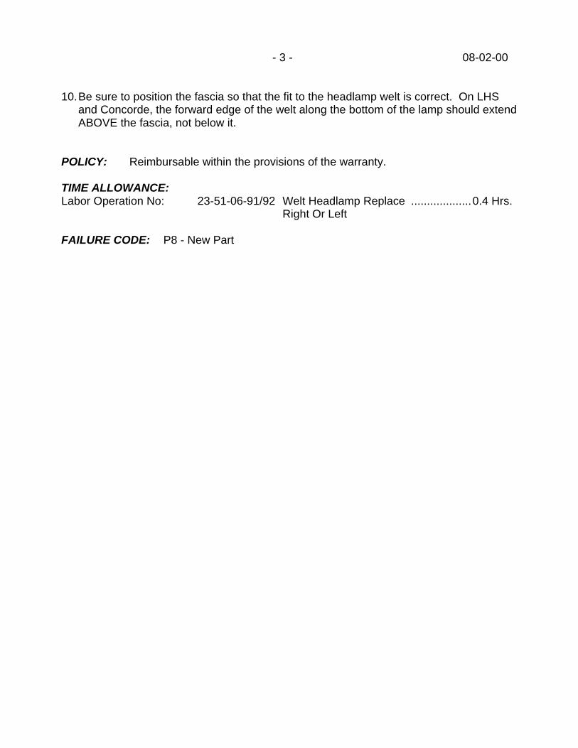
- 3 - 08-02-00
10.Be sure to position the fascia so that the fit to the headlamp welt is correct. On LHSand Concorde, the forward edge of the welt along the bottom of the lamp should extendABOVE the fascia, not below it.
POLICY: Reimbursable within the provisions of the warranty.
TIME ALLOWANCE:Labor Operation No: 23-51-06-91/92 Welt Headlamp Replace ...................0.4 Hrs.
Right Or Left
FAILURE CODE: P8 - New Part


Form TSB-003 Rev. 1.06
NUMBER: 08-03-00
GROUP: Electrical
DATE: Feb. 11, 2000
THIS BULLETIN SUPERSEDES TECHNICAL SERVICE BULLETIN NUMBER 08-47-98,DATED JUNE 26, 1998, WHICH SHOULD BE REMOVED FROM YOUR FILES ANDNOTED IN THE TECHNICAL SERVICE BULLETIN BOUND MANUAL, PUBLICATIONNUMBER 81-699-99003. THE REVISIONS ARE HIGHLIGHTED WITH **ASTERISKS**.THE REVISION INVOLVES THE ADDITION OF ERRATIC OPERATION OF THEPOWER MIRRORS TO THE SYMPTOMS
SUBJECT:**Erratic operation of the power door locks, remote keyless entry system, power windowsor power mirrors**.
OVERVIEW:This bulletin involves Flash Re-programming the Body Control Module and resetting theRemote Keyless Entry Module.
MODELS:1999 (WJ) Grand Cherokee
SYMPTOM/CONDITION:**Intermittent and erratic operation of the power door locks, remote keyless entry (RKE),power mirrors and power windows. This can be the result of a communication error in theDoor Switch Module located in the passengers' door. Revised programming in the BodyControl Module has been developed to address this issue**.
DIAGNOSIS:Due to the intermittent nature of this condition, diagnosis may be difficult. If customerscomplain of intermittent or erratic operation of any of the systems listed above, perform theRepair Procedure.
EQUIPMENT REQUIRED:1 CH6000 Scan Tool (DRB III®)1 CH7035 General Purpose Interface Bus Cable (GPIB)1 CH7000/7001 J1962 Cable
REPAIR PROCEDURE:
1. Connect the DRB III® to the MDS II using cables CH 7023 and 7038.2. From the DRB III® main menu select “2", Connect the MDS II.3. From the DRB III® select “1", MDS Diagnostics or DRB update.
This bulletin is supplied as technical information only and is not an authorization for repair. No part of this publication may be reproduced, stored in a retrieval system, ortransmitted, in any form or by any means, electronic, mechanical, photocopying, recording, or otherwise, without written permission of DaimlerChrysler Corporation.
THIS REPAIR IS COMPATIBLE WITH DAIMLERCHRYSLER'S MOBILE SERVICE PROGRAM ANDDOES NOT REQUIRE HOISTS OR OTHER FULL SERVICE FACILITY SPECIAL EQUIPMENT.

08-03-00 -2-
4. From the diagnostic menu, select “Vehicle Controller Program”.5. From the Controller Programming options select “DRB III® Stand Alone Programming
By Vehicle Description”.6. From the Stand Alone Vehicle Description Menu input the vehicle Information.7. Select Body Control Module Flash.8. Select “F4" and the DRB III® will display “ 3 of 3 Updates Loaded, 1 New Part Number
Loaded Display Part Numbers (Y/N).9. Select “No”.10. Disconnect DRB III® from MDS I.11. Connect the DRB III® to the vehicle diagnostic connector, using cable CH 7001.12. Turn the ignition key ON (engine OFF).13. From the Main Menu, select - “2"- “Connect MDS I or MDS II”.14. Select - “1” - “ MDS Diagnostics or DRB Update”.15. Select “Yes” to “Reprogram Vehicle”.16. Select “ Page Fwd” to begin programming.17. Select “Enter” on the DRB III.18. The DRB III® will display the bar graph indicating percentage complete. Turn the
Ignition key off and then on when instructed.19. The DRB III® will display “BCM Reprogramming Was Successful”.20. When the DRB III® asks, “ Do You Want To Reprogram another Vehicle”, select “No”.
NOTE: LABELS INDICATING THE NEW PART NUMBER ARE NOT REQUIREDFOR BODY CONTROLLER REPROGRAMMING.
21. If any error codes are present, the Door Switch Module will require resetting tocomplete the repair. Remove fuse 12 from the Power Distribution Center for 10seconds and install it in the same location. This will remove power from themodule and reset it when power is applied.
POLICY: Reimbursable within the provisions of the warranty.
TIME ALLOWANCE:Labor Operation No: 08-19-60-90 ................................................................0.2 Hrs.
FAILURE CODE: FM - Flash Module

Form TSB-004 Rev. 1.05
NUMBER: 08-04-00
GROUP: Electrical
DATE: Feb. 18, 2000
SUBJECT:Light Bulb Applications And Replacement Information
MODELS:2001 (PT) PT Cruiser
DISCUSSION:The PT Cruiser uses separate low beam headlight and high beam headlight bulbs. Thefront park/turn signal and marker are all included in one bulb. The bulb part numbers andreplacement instructions are provided below.
Component - Bulb Mopar Part # Industry Part #Low Beam Headlight - L0009006XS 9006XSHigh Beam Headlight - L0009005XS 9005XSFront Park/Turn Signal Light/Marker Light - L004157NAK 4157NAKXFront Fog Light - L0009006 9006Backup Light - L0003157 3157-P27/7W
Headlight Bulb Replacement:1. Remove the headlight access cover splash shield.2. Rotate the socket to the left one-quarter turn and remove the bulb.3. Disconnect the electrical connector.
Front Park/ Turn Signal Light/ Marker Bulb Replacement:1. Remove the headlight access cover splash shield.2. Rotate the socket to the left one-quarter turn and remove the bulb.
POLICY: Information Only
This bulletin is supplied as technical information only and is not an authorization for repair. No part of this publication may be reproduced, stored in a retrieval system, ortransmitted, in any form or by any means, electronic, mechanical, photocopying, recording, or otherwise, without written permission of DaimlerChrysler Corporation.


Form TSB-003 Rev. 1.07
NUMBER: 08-05-00
GROUP: Electrical
EFFECTIVE DATE: April 21, 2000
SUBJECT:Intermittent Operation Of The Instrument Cluster
OVERVIEW:This bulletin involves replacing the instrument cluster wire harness connector andassociated wire terminals.
MODELS:1999 (AB) Ram Van/Wagon1999 (AN) Dakota1999 (BR/BE) Ram Truck1999 (DN) Durango
SYMPTOM/CONDITION:The needle of the instrument cluster gauges may intermittently drop to zero and/or thetelltale lamps, such as the AIRBAG warning lamp, may intermittently come on.
DIAGNOSIS:Connect the DRB III to the 16-way Data Link Connector (DLC). Read and record allactive and stored Airbag Control Module (ACM) Diagnostic Trouble Codes (DTC). If aactive and/or stored “No Cluster CCD Bus” DTC is present, perform the Repair Procedure.
PARTS REQUIRED:1 05016640AA Kit, Instrument Cluster Harness Connector Wiring Repair
Kit Includes:(1) Cluster Connector With Terminated Wires(1) Pink Wire With Terminal(1) Yellow Wire With Terminal(1) Black Wire With Terminal(1) Black/Orange Wire With Terminal(10) Heat Shrink Tubing(12) Splice Bands
EQUIPMENT REQUIRED:Soldering GunRosin Core SolderHeat Gun
This bulletin is supplied as technical information only and is not an authorization for repair. No part of this publication may be reproduced, stored in a retrieval system, ortransmitted, in any form or by any means, electronic, mechanical, photocopying, recording, or otherwise, without written permission of DaimlerChrysler Corporation.

08-05-00 -2-
REPAIR PROCEDURE:
1. Disconnect and isolate the battery negative cable. On vehicles equipped with the5.9L Cummins diesel engine, disconnect and isolate both battery negative cables.
2. Remove the instrument cluster bezel. Refer to the appropriate Service Manual,Group 8E, for information regarding Instrument Cluster Bezel removal.
3. Remove the four screws that secure the instrument cluster to the instrument panel(Figure 1).
4. If the vehicle is equipped with an automatic transmission, place the automatictransmission gear selector into the PARK position and perform Steps 5 and 6. If thevehicle is equipped with a manual transmission, set the parking brake and proceed toStep 7.
5. Remove the steering column opening cover.a. On Dakota/Durango/Ram Truck Models, remove the three screws that secure
the lower edge of the steering column opening cover to the lower instrumentpanel reinforcement (Figure 2). Using a trim stick or other suitable wide flat-bladed tool, gently pry the upper edge of the opening cover just below thecluster bezel on each side of the steering column away from the instrumentpanel far enough to disengage the snap clip retainers from the receptacles in theinstrument panel. Then, remove the steering column opening cover from theinstrument panel.
THIS REPAIR IS COMPATIBLE WITH DAIMLERCHRYSLER'S MOBILE SERVICE PROGRAM ANDDOES NOT REQUIRE HOISTS OR OTHER FULL SERVICE FACILITY SPECIAL EQUIPMENT.
1 - INSTRUMENT CLUSTER2 - SCREW3 - PRNDL CABLE4 - SELF-DOCKING WIRE HARNESS CONNECTOR
FIGURE 1 (RAM TRUCK SHOWN)

-3- 08-05-00
b. On Ram Van/Wagons, move tilt steering column to the fully raised position, (ifequipped). Remove the end cap from the left end of the instrument panel.Remove the three screws that secure the lower edge of the steering columnopening cover to the knee blocker. Remove the two screws that secure theoutboard end of the steering column opening cover to the left side of theinstrument panel end bracket. Using a trim stick or other suitable wide flat-bladed tool, gently pry the upper edge of the opening cover just below thecluster bezel to disengage the four snap clip retainers that secure the cover tothe instrument panel. Then, remove the steering column opening cover from theinstrument panel.
6. Disconnect the shift indicator from the steering column (Figure 3).
1 - SNAP CLIPS2 - COVER3 - SCREW
FIGURE 2 (DAKOTA SHOWN)
1 - PRNDL LEVER2 - THUMB SCREW3 - CABLE RETAINER4 - PRNDL CABLE
FIGURE 3 (DURANGO SHOWN)

08-05-00 -4-
7. Pull the instrument cluster rearward far enough to disengage the two self-dockinginstrument panel wire harness connectors from the connector receptacles on the backof the cluster housing.
8. Remove the instrument cluster from the instrument panel.9. Separate the right side (passenger side) wire harness connector from the self-docking
receptacle on the instrument panel.10. From the back of the right side instrument cluster wire harness connector, remove
approximately three inches of the electrical wire wrapping tape.11. Assemble the new instrument panel wire harness connector p/n 05016640AA by
inserting the appropriate color-coded terminal/wire into the appropriate wire terminalcavity. The charts on the following page identify proper wire color code connectorcavity locations.
RAM VAN DAKOTACAVITY
NUMBERORIGINAL WIRE
COLORREPLACEMENT
WIRE COLORCAVITY
NUMBERORIGINAL WIRE
COLORREPLACEMENT
WIRE COLOR1 OPEN OPEN 1 YL YL2 DB/WT DB/WT 2 OR/LG DB/WT3 WT/PK WT/BK 3 WT/BK WT/BK4 BK/DG BK/DG 4 BK/LG BK/LG5 OPEN OPEN 5 BK BK6 PK/WT PK 6 PK PK7 OPEN OPEN 7 OPEN OPEN8 YL/OR YL 8 BK/WT BK/OR9 WT/BK WT/BK 9 WT/BK WT/BK10 VT/BR VT/BR 10 VT/BR VT/BR
RAM TRUCK DURANGOCAVITY
NUMBERORIGINAL WIRE
COLORREPLACEMENT
WIRE COLORCAVITY
NUMBERORIGINAL WIRE
COLORREPLACEMENT
WIRE COLOR1 OPEN OPEN 1 BK/OR BK/OR2 DB/WT DB/WT 2 DB/WT DB/WT3 WT/LG WT/BK 3 WT/BK WT/BK4 BK/LG BK/LG 4 BK/TN BK/LG5 BK/OR BK 5 BK BK6 YL YL 6 PK PK7 OPEN OPEN 7 OPEN OPEN8 OR/BK (DIESEL) BK/OR (DIESEL) 8 BK/WT YL9 WT/BK WT/BK 9 WT/BK WT/BK10 VT VT/BR 10 VT/BR VT/BR
INSTRUMENT CLUSTER C1 CONNECTOR

-5- 08-05-00
12. Push in the wire connector primary lock. The red primary lock is in its proper positionwhen the lock is flush with the back of the housing.
13. Use one of the two following methods to splice the wires from the new connector tothe wires from the original connector. It is recommended to cut and splice one wire ata time to help prevent accidentally splicing the wrong wires together. The previouscharts should be used to ensure that the proper wires are spliced together. Splicejoints should be staggered about 1/2 in. apart to help limit the size of the wire bundle.
CAUTION: SOME VEHICLES HAVE MORE THAN ONE WIRE WITH THE SAMECOLOR COMBINATION. IT IS NOT ADVISED TO CUT ALL OF THECONNECTOR WIRES AT ONCE.
WIRE SPLICING METHOD 11. Remove one (1) inch of insulation from each wire that needs to be spliced.2. Place a piece of heat shrink tubing on one side of the wire. Make sure the tubing will
be long enough to cover and seal the entire repair area.3. Spread the strands of wire apart on each exposed portion of the wire that needs to be
spliced (Figure 4 - Example 1).
4. Push the two ends of the wires together until the strands of wire are close to theinsulation (Figure 4 - Example 2).
5. Twist the wires together (Figure 4 - Example 3).6. Solder the connection together using rosin core type solder only.
FIGURE 4

08-05-00 -6-
CAUTION: DO NOT USE ACID CORE SOLDER.
7. Center the heat shrink tubing over the joint and heat using a heat gun. Heat the jointuntil the tubing is tightly sealed and sealant comes out of both ends of the tubing(Figure 5).
WIRE SPLICING METHOD 21. Remove one-half (1/2) inch of insulation from each wire that needs to be spliced.2. Place a piece of heat shrink tubing on one side of the wire. Make sure the tubing will
be long enough to cover and seal the entire repair area.3. Place the strands of wire overlapping each other inside of the splice clip (Figure 6).
1 - SEALER2 - HEAT SHRINK TUBING
FIGURE 5
1 - SPLICE CLIP
FIGURE 6

-7- 08-05-00
4. Using crimping tool 8272 or equivalent, crimp the splice clip and wires together(Figure 7).
5. Solder the connection together using rosin core type solder only (Figure 8).
CAUTION: DO NOT USE ACID CORE SOLDER.
6. Center the heat shrink tubing over the joint and heat using a heat gun. Heat the jointuntil the tubing is tightly sealed and sealant comes out of both ends of the tubing(Figure 5).
INSTALLATION
1. Secure the bundle of wires together using electrical tape.2. Install the instrument cluster wire harness connector into the self-docking receptacle.3. Position the instrument cluster to the instrument panel.4. If the vehicle is equipped with a manual transmission, proceed to Step 6. If the
vehicle is equipped with an automatic transmission, install the PRNDL cable onto thesteering column PRNDL lever.
1 - CRIMPING TOOL 8272
FIGURE 7
1 - SOLDER2 - SPLICE CLIP3 - SOLDERING IRON
FIGURE 8

08-05-00 -8-
5. Install the steering column opening cover.a. On Dakota/Durango/Ram Truck, position the steering column opening cover to
the instrument panel. Align the snap clip retainers on the steering columnopening cover with the receptacles in the instrument panel. Press firmly on thesteering column opening cover over the snap clip locations until each snap clipis fully engaged in its receptacle. Install and tighten the three screws that securethe lower edge of the steering column opening cover to the lower instrumentpanel reinforcement. Tighten the screws to 2.2 N•m (20 in. lbs.).
b. On Ram Van/Wagon, position the steering column opening cover to theinstrument panel. Align the four snap clip retainers on the steering columnopening cover with the receptacles in the instrument panel. Press firmly on thesteering column opening cover over the snap clip locations until each snap clipis fully engaged in its receptacle. Install and tighten the two screws that securethe outboard end of the steering column opening cover to the left instrumentpanel end bracket. Tighten the screws to 2.2 N•m (20 in. lbs.). Install andtighten the three screws that secure the lower edge of the steering columnopening cover to the knee blocker. Tighten the screws to 2.2 N•m (20 in. lbs.).Install the end cap onto the left end of the instrument panel.
6. Align the instrument cluster with the cluster opening in the instrument panel and pushthe cluster firmly and evenly into place. The instrument panel has two self-dockingwire harness connectors that will be automatically aligned with, and connected to theinstrument cluster connector receptacles when the cluster is installed in theinstrument panel.
7. Install and tighten the four screws that secure the instrument cluster to the instrumentpanel. Tighten the screws to 2.2 N•m (20 in. lbs.).
8. Install the cluster bezel onto the instrument panel. Refer to the appropriate ServiceManual, Group 8E, for information regarding Instrument Cluster Bezel installation.
9. Connect the battery negative cable(s).10. Reset the clock in the radio and verify proper operation of the cluster.
POLICY: Reimbursable within the provisions of the warranty.
TIME ALLOWANCE:Labor Operation No: 08-90-90-96 ................................................................1.3 Hrs.
FAILURE CODE: P8 - New Part

Form TSB-004 Rev. 1.05
NUMBER: 08-06-00
GROUP: Electrical
DATE: Feb. 25, 2000
SUBJECT:Wire Splice Repairs
MODELS:1989 – 1995 (AA) Spirit/Acclaim/LeBaron Sedan1989 – 2000 (AB) Ram Van/Wagon1989 – 1993 (AC) Dynasty/New Yorker/New Yorker Salon1989 – 1993 (AD) Ram Truck1989 – 1994 (AG) Daytona1989 (AH) Lancer/Lebaron GTS1989 – 1995 (AJ) LeBaron Coupe/LeBaron Convertible1989 – 1990 (AK) Aries/Reliant1989 – 1990 (AL) Horizon/Omni1989 (AM) Diplomat/Gran Fury/New Yorker Fifth Avenue1989 – 2000 (AN) Dakota1989 – 1994 (AP) Shadow/Sundance1989 – 1995 (AS) Town & Country/Caravan/Voyager1990 – 1993 (AY) Imperial/New Yorker Fifth Avenue1988 – 1992 (BB) Monaco/Premier1990 – 1994 (BD) Laser/Talon1994 – 2000 (BR/BE) Ram Truck1989 – 1992 (B2) Colt/Summit1992 – 1995 (B3) Colt Vista1989 – 1995 (B7) Stealth (2000 GTX Dodge/Eagle, Canada)1992 – 1995 (B8) Colt Vista Wagon/Summit Wagon1993 – 1994 (B9) Colt/Summit1998 – 2000 (DN) Durango1992 – 1995 (ES) Chrysler Voyager (International Market)1995 – 2000 (FJ) Sebring/Avenger/Talon1996 – 2000 (GS) Chrysler Voyager (International Market)1995 – 2000 (JA) Cirrus/Stratus/Breeze1996 – 2000 (JX) Sebring Convertible1993 – 2000 (LH) Concorde/Intrepid/Vision/LHS/New Yorker/300M1989 – 1992 (MJ) Commanche1996 – 2000 (NS) Town & Country/Caravan/Voyager1995 – 2000 (PL) Neon1997 – 2000 (PR) Prowler1996 – 2000 (SR) Viper/Viper GTS1997 – 2000 (TJ) Wrangler1999 – 2000 (WJ) Grand Cherokee1989 - 2000 (XJ) Cherokee/Wagoneer1989 - 1995 (YJ) Wrangler1996 - 1998 (ZG) Grand Cherokee (International Market)1993 - 1998 (ZJ) Grand Cherokee/Grand Wagoneer
This bulletin is supplied as technical information only and is not an authorization for repair. No part of this publication may be reproduced, stored in a retrieval system, ortransmitted, in any form or by any means, electronic, mechanical, photocopying, recording, or otherwise, without written permission of DaimlerChrysler Corporation.

08-06-00 - 2 -
DISCUSSION:This bulletin provides a revised wire splice procedure and related parts. This is the onlyprocedure approved by DaimlerChrysler Engineering. This procedure must be used anytimea wire splice repair is required.
PARTS REQUIRED:AR 05018395AA Kit, Splice Band, (Refer To Usage Matrix Page 4)
Contains: One Splice Band, p/n 05018396AA, and Heat Shrink TubeAR 05018526AA Kit, Splice Band, (Refer To Usage Matrix Page 4)
Contains: One Splice Band, p/n 05013243AA, and Heat Shrink TubeAR 05018527AA Kit, Splice Band, (Refer To Usage Matrix Page 4)
Contains: One Splice Band, p/n 05013251AA, and Heat Shrink TubeAR 05018528AA Kit, Splice Band, (Refer To Usage Matrix Page 4)
Contains One Splice Band, p/n 05018397AA, and Heat Shrink TubeAR 05018620AA Kit, Splice Band
Contains: 200 Splice Bands, 50 Of Each Size200 Heat Shrink Tubes, p/n 04778570Instruction Sheet
NOTE: IF THE REPAIR REQUIRES ADDITIONAL WIRE ALWAYS USE THE SAME ORNEXT LARGER GAUGE WIRE.
REPAIR PROCEDURE:1. Remove one-half (1/2) inch of insulation from each wire that needs to be spliced.2. Place a piece of sealant lined heat shrink tubing, p/n 04778570, on one side of the wire.
Make sure the tubing will be long enough to cover and seal the entire repair area.3. Place the strands of wire overlapping each other inside of the splice band (Figure 1).
4. Using crimping tool, Miller p/n 8272, crimp the splice band and wires together (Figure 2).
FIGURE 1
1 - SPLICE BAND

- 3 - 08-06-00
5. Solder the connection together using rosin core type solder only (Figure 3).
CAUTION: DO NOT USE ACID CORE SOLDER.
6. Center the heat shrink tubing over the joint and heat using a heat gun. Heat the jointuntil the tubing is tightly sealed and sealant comes out of both ends of the tubing (Figure4).
POLICY: Information Only
FIGURE 4
1 - SEALER2 - HEAT SHRINK TUBE
FIGURE 2
1 - CRIMPING TOOL
FIGURE 3
1 - SOLDER2 - SPLICE BAND3 - SOLDERING IRON
FIGURE 2
1 - CRIMPING TOOL

08-06-00 - 4 -
SPLICE BAND USAGE MATRIXAll crimped splices are to be soldered with rosin core solder only.Splices are to be covered and sealed by shrink tube 04778570.
Splice bandpackagerequired
TWO WIRE splices.
. . . to ONE wire this size
22 20 18 16 14 12ONE wirethis size
. . .
22 05018395AA 05018395AA 05018395AA 05018395AA 05018526AA 05018527AA
20 05018395AA 05018395AA 05018395AA 05018526AA 05018527AA
18 05018395AA 05018526AA 05018526AA 05018527AA
16 05018526AA 05018527AA 05018527AA
14 05018527AA 05018528AA
12 05018528AA
Splice bandpackagerequired
THREE WIRE splices.
. . . to TWO wires this size
22 20 18 16 14 12ONE wirethis size
. . .
22 05018395AA 05018395AA 05018526AA 05018526AA 05018527AA Outside crimprange
20 05018395AA 05018395AA 05018526AA 05018526AA 05018527AA Outside crimprange
18 05018395AA 05018395AA 05018526AA 05018527AA 05018528AA Outside crimprange
16 05018395AA 05018526AA 05018526AA 05018527AA 05018528AA Outside crimprange
14 05018526AA 05018526AA 05018527AA 05018527AA 05018528AA Outside crimprange
12 05018527AA 05018527AA 05018528AA 05018528AA Outside crimprange
Outside crimprange

Form TSB-003 Rev. 1.08 February 3, 2000
NUMBER: 08-07-00
GROUP: Electrical
DATE: Mar. 03, 2000
SUBJECT:Erroneous MIL Due To DTC P0443 (Purge Ckt) And/Or A Possible Key-Off Battery Draw
OVERVIEW:This bulletin involves the replacement of the heater-A/C blower motor relay.
MODELS:1999 (DN) Durango
SYMPTOM/CONDITION:The vehicle Malfunction Indicator Lamp (MIL) may illuminate due to a Diagnostic TroubleCode (DTC) P0443 – Evaporative Purge Solenoid Circuit. The MIL will normally illuminateshortly after the initial start of the vehicle engine due to a previously performed diagnosticcircuit test by the powertrain control module (PCM).
NOTE: THIS CONDITION MAY CAUSE A SMALL ELECTRICAL DRAIN ON THEBATTERY, WHEN THE IGNITION KEY IS IN THE OFF POSITION, WHICHOVER AN EXTENDED PERIOD OF TIME MAY DISCHARGE THE BATTERY.
While the evaporative purge solenoid electrical circuit is working as designed, the DTCP0443 generated may be due to an electrical feedback condition into the powertraincontrol module. The electrical feedback may be due to the heater-A/C blower motor relayremaining energized after the engine has been turned off. If the relay remains closed(energized), and if the heater-A/C selector is in the OFF mode, then electrical feedbackmay partially power the PCM.
The new blower motor relay is designed to prevent this condition from occurring.
DIAGNOSIS:1. If DTC’s other than P0443 are present then they must be diagnosed and corrected
prior to proceeding any further with this Technical Service Bulletin (TSB).2. If only DTC P0443 (Evaporative Purge Solenoid Circuit) is occurring, then verify that
TSB #18-35-98 has been performed and proceed with the Repair Procedure.
PARTS REQUIRED:1 05018962AA Relay, Blower Motor
REPAIR PROCEDURE:The heater-A/C blower motor relay is located in the Power Distribution Center (PDC) whichcan be found in the engine compartment.
1. Install the new heater-A/C blower motor relay (p/n 05018962AA) into the PDC.2. If still present, erase the current P0443 DTC from the memory of the PCM.
This bulletin is supplied as technical information only and is not an authorization for repair. No part of this publication may be reproduced, stored in a retrieval system, ortransmitted, in any form or by any means, electronic, mechanical, photocopying, recording, or otherwise, without written permission of DaimlerChrysler Corporation.

08-07-00 -2-
POLICY: Reimbursable within the provisions of the warranty.
TIME ALLOWANCE:Labor Operation No: 08-65-15-91 ............................................................... 0.2 Hrs.
FAILURE CODE: P8 – New Part

Form TSB-003 Rev. 1.07
NUMBER: 08-08-00
GROUP: Electrical
DATE: March 17, 2000
THIS BULLETIN SUPERSEDES TECHNICAL SERVICE BULLETIN NUMBER 08-16-99REV. A, DATED JUNE 11, 1999, WHICH SHOULD BE REMOVED FROM YOUR FILES.THIS BULLETIN IS A COMPLETE REVISION, WHICH INVOLVES REPLACING ANDREPROGRAMMING THE TRANSMITTER ASSEMBLY, INSTEAD OF REPLACING THECASE HALVES. NO ASTERISKS HAVE BEEN USED TO HIGHLIGHT CHANGES.
SUBJECT:Inoperative or Intermittent Remote Keyless Entry (RKE) Transmitter
OVERVIEW:This bulletin involves replacing and reprogramming the RKE transmitter.
MODELS:1998 - 2000 (LH) Concorde/Intrepid/LHS/300M1999 - 2000 (AN) Dakota1999 - 2000 (DN) Durango1999 - 2000 (BR/BE) Ram Truck1999 - 2000 (XJ) Cherokee1999 - 2000 (WJ) Grand Cherokee1999 - 2000 (AB) Ram Wagon2000 (PL) Neon
SYMPTOM/CONDITION:Inoperative RKE transmitter. This condition may be intermittent and will have similarsymptoms to a dead transmitter battery.
DIAGNOSIS:If the vehicle exhibits this condition, perform the Repair Procedure.
PARTS REQUIRED:AR 04602268AC Transmitter -LHAR 56045497AC Transmitter - AN/DN/BR/BEAR 56036859AD Transmitter - XJ/WJ (Use with 56036859,
56036859AB or 56036859AC)AR 56036860AD Transmitter - WJ (Use with 56036860,
56036860AB or 56036860AC)AR 04759008AD Transmitter - PLAR 56045191AD Transmitter - AB
This bulletin is supplied as technical information only and is not an authorization for repair. No part of this publication may be reproduced, stored in a retrieval system, ortransmitted, in any form or by any means, electronic, mechanical, photocopying, recording, or otherwise, without written permission of DaimlerChrysler Corporation.

08-08-00 -2-
REPAIR PROCEDURE:
1. Replace RKE transmitter with the appropriate part number listed above.2. Using the procedure outlined in the appropriate service manual, reprogram the RKE
system to the new transmitter.
NOTE: IT IS IMPORTANT TO NOTE THAT ALL OF THE TRANSMITTERS THATARE USED IN THE OPERATION OF THIS SYSTEM BE PROGRAMMEDAT THE SAME TIME. IF ONE TRANSMITTER IS PROGRAMMED ANDTHE OTHERS ARE NOT DONE AT THE SAME TIME, THE OTHERTRANSMITTERS WILL BECOME INOPERATIVE. CUSTOMERS MUSTBE INSTRUCTED TO HAVE ALL TRANSMITTERS PRESENT WHEN THISOPERATION IS PERFORMED.
3. Verify transmitter operation by depressing the lock button. It may be necessary todepress the button up to seven times to synchronize the rolling codes.
4. Transfer the keys to the new key ring.
POLICY: Reimbursable within the provisions of the warranty.
TIME ALLOWANCE:Labor Operation No: Replace and Reprogram Transmitter - One or More
08-80-28-91 ................................................................0.2 Hrs.
FAILURE CODE: P8 - New PArt
THIS REPAIR IS COMPATIBLE WITH DAIMLERCHRYSLER'S MOBILE SERVICE PROGRAM ANDDOES NOT REQUIRE HOISTS OR OTHER FULL SERVICE FACILITY SPECIAL EQUIPMENT.
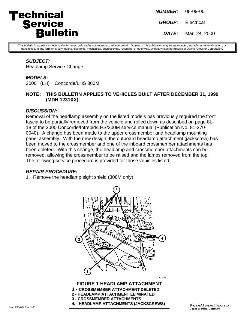
Form TSB-004 Rev. 1.05
NUMBER: 08-09-00
GROUP: Electrical
DATE: Mar. 24, 2000
SUBJECT:Headlamp Service Change
MODELS:2000 (LH) Concorde/LHS 300M
NOTE: THIS BULLETIN APPLIES TO VEHICLES BUILT AFTER DECEMBER 31, 1999(MDH 1231XX).
DISCUSSION:Removal of the headlamp assembly on the listed models has previously required the frontfascia to be partially removed from the vehicle and rolled down as described on page 8L-18 of the 2000 Concorde/Intrepid/LHS/300M service manual (Publication No. 81-270-0040). A change has been made to the upper crossmember and headlamp mountingpanel assembly. With the new design, the outboard headlamp attachment (jackscrew) hasbeen moved to the crossmember and one of the inboard crossmember attachments hasbeen deleted. With this change, the headlamp and crossmember attachments can beremoved, allowing the crossmember to be raised and the lamps removed from the top.The following service procedure is provided for those vehicles listed.
REPAIR PROCEDURE:1. Remove the headlamp sight shield (300M only).
This bulletin is supplied as technical information only and is not an authorization for repair. No part of this publication may be reproduced, stored in a retrieval system, ortransmitted, in any form or by any means, electronic, mechanical, photocopying, recording, or otherwise, without written permission of DaimlerChrysler Corporation.
FIGURE 1 HEADLAMP ATTACHMENT1 - CROSSMEMBER ATTACHMENT DELETED2 - HEADLAMP ATTACHMENT ELIMINATED3 - CROSSMEMBER ATTACHMENTS4. - HEADLAMP ATTACHMENTS (JACKSCREWS)
08-09-00 - 2 -
2. Remove the upper crossmember attachments, both sides (6), headlamp jackscrews(4), windshield filler neck screw (1), and speed control servo screw (1) (Figure 1).
3. Lift and prop the crossmember above the headlamp on the side being serviced, andremove the electrical connectors from the headlamp.
4. Pull headlamp up and under crossmember to remove it from the vehicle..5. To install the headlamp, reverse the above procedure.
POLICY: Information Only

Form TSB-004 Rev. 1.05
NUMBER: 08-10-00
GROUP: Electrical
DATE: Mar. 24, 2000
SUBJECT:Dead Battery And/Or Ignition Operated Electrical Accessories Function With Ignition OFF
MODELS:2000 (AN) Dakota1998 - 2000 (DN) Durango
NOTE: THIS BULLETIN APPLIES TO DURANGO AND DAKOTA QUAD CABVEHICLES.
DISCUSSION:Batteries that go dead for no apparent reason must include an “Ignition-Off Draw Test” aspart of the diagnosis. Ignition-Off Draw Test procedures can be found in the 2000Durango or 2000 Dakota Service Manual on pages 8A-13 and 8A-14. If the Ignition-OffDraw Test identifies that ignition operated electrical accessories still function although theignition switch is OFF, the root cause of the problem may be difficult to diagnose and couldeven lead to misdiagnosis. Components such as the radio and rear wiper circuit aresupplied with ignition voltage and cannot operate with the ignition switch OFF unless theyare back fed by other electrical components. Electrical circuits that are fed with bothbattery voltage and ignition voltage may be the most likely source of battery voltage backfeeding. Battery voltage back feeding can occur when a short across the battery voltagecircuit and the ignition voltage circuit occurs internal to the component.
The power door lock switch is a switch that is fed with both battery voltage and ignitionvoltage. If the power door lock switch becomes shorted internally across the battery feedand the ignition feed, components such as the blower fan, rear wiper, and the radio mayfunction even with the ignition key in the OFF position. If the component is left ON, thecustomer may eventually be left with a dead battery. The easiest way to determine if thepower door lock switch is the root cause of the problem is to disconnect the power doorlock switch. If the symptoms and the ignition-off draw are no longer apparent, the rootcause is most likely the power door lock switch. To repair the condition, the power doorlock switch must be replaced. If the symptoms and the ignition-off draw are still apparent,reconnect the power door lock switch and continue diagnosing the ignition-off draw.
POLICY: Information Only
This bulletin is supplied as technical information only and is not an authorization for repair. No part of this publication may be reproduced, stored in a retrieval system, ortransmitted, in any form or by any means, electronic, mechanical, photocopying, recording, or otherwise, without written permission of DaimlerChrysler Corporation.

Form TSB-004 Rev. 1.03
NUMBER: 08-11-00
GROUP: Electrical
DATE: March 24, 2000
SUBJECT:Recordable Compact Discs Used in Automotive CD players
MODELS:1989 - 2000 (AB) Ram Van/Wagon1989 - 2000 (AN) Dakota1994 - 2000 (BR/BE) Ram Truck1998 - 2000 (DN) Durango1995 - 1999 (FJ) Sebring/Avenger/Talon1995 - 1999 (JA) Cirrus/Stratus/Breeze1993 - 1999 (LH) Concorde/Intrepid/Vision/LHS/New Yorker/300M1996 - 2000 (NS) Town & Country/Caravan/Voyager1995 - 2000 (PL) Neon1997 - 1999 (PR) Prowler1996 - 1999 (SR) Viper/Viper GT1997 - 2000 (TJ) Wrangler1999 - 2000 (WJ) Grand Cherokee1997 - 2000 (XJ) Cherokee1993 - 1998 (ZJ) Grand Cherokee
DISCUSSION:Some recordable compact disc media, such as CD-R and CD-RW, may not comply with thestandard CD format used in automotive CD players. When these CD's are used, customersmay encounter error messages, skipping, or delaminating of the labels, which can cause aneject failure. It is important to question whether these kinds of CD media are being used. Whencustomers encounter these symptoms, check the system with a known playable CD. Explainthat the media may not be compatible with some automotive CD players. Replacing orexchanging the CD player will not address these issues.
POLICY: Information Only
This bulletin is supplied as technical information only and is not an authorization for repair. No part of this publication may be reproduced, stored in a retrieval system, ortransmitted, in any form or by any means, electronic, mechanical, photocopying, recording, or otherwise, without written permission of DaimlerChrysler Corporation.


Form TSB-003 Rev. 1.08 February 3, 2000
NUMBER: 08-12-00
GROUP: Electrical
DATE: April 7, 2000
THIS BULLETIN SUPERSEDES TECHNICAL SERVICE BULLETIN 08-33-99, DATEDOCT. 8, 1999, WHICH SHOULD BE REMOVED FROM YOUR FILES AND NOTED INTHE 1999 TECHNICAL SERVICE BULLETIN MANUAL (PUBLICATION NO. 81-699-00004). ADDITIONAL VEHICLE LINES HAVE BEEN ADDED AND ARE MARKEDWITH **ASTERISKS**.
SUBJECT:Instrument Cluster Gauge Pointers On Wrong Side Of Pointer Stops.
MODELS: 2000 (PL) Neon**2000 (JA) Cirrus/Stratus****2000 (JX) Sebring****2000 (TJ) Wrangler****2000 (XJ) Cherokee**
DISCUSSION:If a vehicle/ instrument cluster is received with the instrument cluster gauge pointers on thewrong side of the pointer stops, the cluster "Self Test" should be run to reset the pointers.
The instrument cluster "Self Test" is initiated by pressing and holding the trip-reset buttonand turning the ignition on without cranking the engine. The instrument cluster will light theindicators except for the turn signals, the high beam, and the fog lamps. The gaugepointers should then step through the scales and then sweep back to the proper side of thepointer stops.
POLICY: Information Only
This bulletin is supplied as technical information only and is not an authorization for repair. No part of this publication may be reproduced, stored in a retrieval system, ortransmitted, in any form or by any means, electronic, mechanical, photocopying, recording, or otherwise, without written permission of DaimlerChrysler Corporation.


Form TSB-004 Rev. 1.05
NUMBER: 08-13-00
GROUP: Electrical
DATE: April 14, 2000
SUBJECT:Lack Of Bass Sound Coming From Rear Speakers
MODELS:2000 (AN) Dakota
NOTE: THIS BULLETIN APPLIES TO DAKOTA STANDARD CAB VEHICLES.
DISCUSSION:On the Dakota Standard Cab vehicle, the stereo system has been designed to get thehighest quality sound from the speakers when the fader controls are equalized front torear. The front speakers of the stereo system provide the high quality bass tones for thesystem. The rear speakers are not designed to provide high quality bass tones. If thefader controls are positioned so that the majority of the sound is directed to the rearspeakers, the lack of good quality bass tones may be noticed.
When diagnosing stereo system concerns regarding poor quality sound coming from therear speakers, verify the operation of the front speakers in comparison to the rearspeakers. If the front speakers have good quality sound coming from them (including basstones) and the rear speakers have good quality sound with the exception of bass tones,the system is operating as designed and no repair attempts should be made.
NOTE: DO NOT MAKE ANY ATTEMPTS TO REPAIR THE VEHICLE’S STEREOSYSTEM FOR CUSTOMER COMPLAINTS PERTAINING TO LACK OF GOODQUALITY BASS TONES COMING FROM REAR SPEAKERS.
POLICY: Information Only
This bulletin is supplied as technical information only and is not an authorization for repair. No part of this publication may be reproduced, stored in a retrieval system, ortransmitted, in any form or by any means, electronic, mechanical, photocopying, recording, or otherwise, without written permission of DaimlerChrysler Corporation.


Form TSB-003 Rev. 1.07
NUMBER: 08-14-00
GROUP: Electrical
DATE: April 14, 2000
SUBJECT:Fuel Gauge Does Not Register Full
OVERVIEW:This bulletin involves replacing the instrument cluster.
MODELS:2001 (PT) PT Cruiser
NOTE: THIS BULLETIN APPLIES TO VEHICLES BUILT PRIOR TO MARCH 22, 2000(MDH 0322XX).
SYMPTOM/CONDITION:The customer may report that the fuel gauge needle does not reach the full mark with thefuel tank full, even after topping the tank off.
DIAGNOSIS:With the vehicle on a flat surface and the ignition key in the "OFF" position, fill the fueltank. Turn the ignition on and note the fuel needle position. If the fuel gauge needle doesnot reach the full mark, perform the Repair Procedure.
PARTS REQUIRED:Replacement parts are available through your DaimlerChrysler Authorized Service Center.Follow the Global Parts Order Process (GPOP) Exchange Order Processing instructions inthe Special Components section of the Warranty Administration Manual.
REPAIR PROCEDURE:1. Remove and replace the instrument cluster following the procedure in the 2001 PT
Cruiser Service Manual (Publication No. 81-370-1111) beginning on page 8E-11.
POLICY: Reimbursable within the provisions of the warranty.
TIME ALLOWANCE:Labor Operation No: 08-45-10-91 ...............................................................0.4 Hrs.
FAILURE CODE: P8 - New Part
This bulletin is supplied as technical information only and is not an authorization for repair. No part of this publication may be reproduced, stored in a retrieval system, ortransmitted, in any form or by any means, electronic, mechanical, photocopying, recording, or otherwise, without written permission of DaimlerChrysler Corporation.


Form TSB-003 Rev. 1.07
NUMBER: 08-15-00
GROUP: Electrical
DATE: Apr. 21, 2000
SUBJECT:Intermittent Instrument Panel Speaker Operation/Static
OVERVIEW:This bulletin involves installing a new speaker/amplifier assembly
MODELS:1999 – 2000 (NS) Town & Country/Caravan/Voyager1999 – 2000 (GS) Chrysler Voyager (International Market)
NOTE: THIS BULLETIN APPLIES TO VEHICLES EQUIPPED WITH THE INFINITY
SOUND SYSTEM SALES CODES (RCE, RBN, AND RAZ).
SYMPTOM/CONDITION:Intermittent operation/static may occur in front I/P speakers.
DIAGNOSIS:1. Turn the ignition key to the RUN position.2. Turn the radio ON.3. Insert a known good quality CD or Tape into the sound system.4. Increase and decrease the volume while listening for static.5. Move the fade control fully forward, and adjust the speaker balance control from left to
right while listening for static and/or intermittent operation of the speakers.6. Increase and decrease the volume while listening for static and/or intermittent
operation of the speakers.7. If the static/intermittent operation is present and is coming from the same speaker(s)
even if the fade and speaker R/L controls are changed and the static intermittentoperation does not change with volume, the static may be due to a failed speakeramplifier. Perform the following Repair Procedure to replace the speaker amplifier.
8. If static/intermittent operation is present and the static/intermittent operation changesfrom speaker to speaker as the fade and speaker R/L controls are operated, thestatic/intermittent operation may be due to a malfunctioning radio and this bulletindoes not apply.
PARTS REQUIRED:
AR (2) 04685572AG Speaker, Infinity DoorAR (8) 06504014 Retainer, Door Trim Panel
This bulletin is supplied as technical information only and is not an authorization for repair. No part of this publication may be reproduced, stored in a retrieval system, ortransmitted, in any form or by any means, electronic, mechanical, photocopying, recording, or otherwise, without written permission of DaimlerChrysler Corporation.

08-15-00 -2-
REPAIR PROCEDURE:
NOTE: THE RIGHT FRONT DOOR SPEAKER CONTAINS THE AMPLIFIER FORBOTH RIGHT FRONT DOOR AND RIGHT INSTRUMENT PANEL (I/P)SPEAKERS. IF THE STATIC OR THE INTERMITTENT OPERATION OF THESPEAKER OCCURS IN THE RIGHT I/P SPEAKER OF THE VEHICLE,REPLACE THE RIGHT FRONT DOOR SPEAKER. LIKEWISE, THE LEFTFRONT DOOR SPEAKER CONTAINS THE AMPLIFIER FOR BOTH LEFTFRONT DOOR AND LEFT I/P SPEAKERS. IF THE STATIC OR THEINTERMITTENT OPERATION OF THE SPEAKER OCCURS IN THE LEFT I/PSPEAKER OF THE VEHICLE, REPLACE THE LEFT FRONT DOORSPEAKER. DO NOT REPLACE THE RIGHT OR LEFT I/P SPEAKERS.
1. Remove the front door speaker(s) containing the malfunctioning amplifier. Refer topage 8F-10 of the 2000 Town & Country, Caravan and Voyager Service Manual(Publication No. 81-370-0005) for information regarding front door speaker removaland installation.
POLICY: Reimbursable within the provisions of the warranty.
TIME ALLOWANCE:Labor Operation No:
08-60-70-94 Replace One Infinity Door Speaker ...........................................0.4 Hrs.08-60-70-95 Replace Both Infinity Door Speakers ........................................0.6 Hrs.
FAILURE CODE: 61 - Intermittent Operation
THIS REPAIR IS COMPATIBLE WITH DAIMLERCHRYSLER'S MOBILE SERVICE PROGRAM ANDDOES NOT REQUIRE HOISTS OR OTHER FULL SERVICE FACILITY SPECIAL EQUIPMENT.

Form TSB-003 Rev. 1.07
NUMBER: 08-16-00
GROUP: Body
DATE: April 28, 2000
SUBJECT:Front Door Speaker Buzz
OVERVIEW:This bulletin involves installing a urethane foam pad between the inner door panel and thedoor trim.
MODELS:1994 - 2000 (BR/BE) Ram Truck
SYMPTOM/CONDITION:Buzz noise coming from the front door speaker(s). The noise may be more noticeablewhile listening to “talk” radio segments with deep male voices.
DIAGNOSIS:Tune the radio to “talk” radio program preferably with male voices. Adjust the equalizer toachieve maximum bass tones, if equipped. If noise can be isolated to the front doorspeakers, or the owner describes noise in the front door speaker, perform the RepairProcedure.
PARTS REQUIRED:2 05018968AA Kit, FoamAR (26) 06505878AA Clips, Door Trim Attaching
REPAIR PROCEDURE:
1. Roll the window(s) down.2. Disconnect and isolate the battery negative cable. On vehicles equipped with a diesel
engine, disconnect and isolate both battery negative cables.3. On vehicles equipped with a manual window regulator, remove the window crank
(Figure 1).4. Remove the screw that attaches the trim panel to the outside mirror frame (Figure 2).5. Remove the screws that attach the pull cup to the door.6. Using a trim panel removal tool such as Snap On tool A161B, disengage the trim
panel retaining clips from the door. Base models, have eleven trim panel retainingclips (clips 12 and 13 not used) and premium models have thirteen (Figure 3). It isvery important that a trim panel tool is used to separate each retaining clip fromthe door.
This bulletin is supplied as technical information only and is not an authorization for repair. No part of this publication may be reproduced, stored in a retrieval system, ortransmitted, in any form or by any means, electronic, mechanical, photocopying, recording, or otherwise, without written permission of DaimlerChrysler Corporation.
THIS REPAIR IS COMPATIBLE WITH DAIMLERCHRYSLER'S MOBILE SERVICE PROGRAM ANDDOES NOT REQUIRE HOISTS OR OTHER FULL SERVICE FACILITY SPECIAL EQUIPMENT.

08-16-00 -2-
FIGURE 11 - WINDOW CRANK REMOVAL TOOL2 - WINDOW CRANK
FIGURE 21 - POWER MIRROR2 - SCREW3 - POWER MIRROR CONTROL4 - SCREW5 - TRIM PANEL6 - DOOR LOCK BUTTON7 - POWER WINDOW HARNESS8 - POWER MIRROR HARNESS

-3- 08-16-00
CAUTION: DAMAGE TO THE DOOR TRIM PANEL MAY OCCUR IF THE DOOR TRIMPANEL RETAINING CLIPS ARE SEPARATED FROM THE DOORWITHOUT USING A TRIM PANEL REMOVING TOOL. DOOR PANELSSHOULD NEVER BE REMOVED BY HAND.
7. While holding the bottom of the trim panel away from the door, simultaneously liftupward and inboard to detach the trim panel from the door.
8. Peel the protective backing from the foam (from Foam Kit p/n 05018968AA) and placethe foam onto the inner door panel trim as shown in Figure 4.
FIGURE 3 - DOOR TRIM PANEL RETAINING CLIP LOCATIONS

08-16-00 -4-
9. Remove all door trim panel retaining clips10. Install new door trim panel retaining clips p/n 06505878AA onto the door trim panel.11. Position the trim panel onto the door.12. Engage all door trim panel attaching clips around the perimeter of the trim panel,
attaching trim panel to the inner door.13. Install the screws securing the pull cup to the inner door panel.14. Install the screw attaching the trim panel to the outside mirror frame.15. Install the window crank, if equipped.16. Perform Steps 3 through 15 to the other door trim panel.17. Connect the battery negative cable(s) and reset the clock.18. Roll the windows up.
POLICY: Reimbursable within the provisions of the warranty.
TIME ALLOWANCE:Labor Operation No: 23-20-22-92 ................................................................ 0.4 Hrs.
FAILURE CODE: C2 - Panel Interference
FIGURE 41 - ATTACH FOAM TO DOOR TRIM PANEL ON THESE TWO LOCATIONS

Form TSB-003 Rev. 1.07
NUMBER: 08-17-00
GROUP: Electrical
DATE: May 12, 2000
THIS BULLETIN SUPERSEDES TECHNICAL SERVICE BULLETIN 08-44-99, DATEDDEC. 31, 1999, WHICH SHOULD BE REMOVED FROM YOUR FILES AND NOTED INTHE 1999 TECHNICAL SERVICE BULLETIN MANUAL (PUBLICATION NO. 81-699-00004). THIS IS A COMPLETE REVISION AND NO ASTERISKS HAVE BEEN USEDTO HIGHLIGHT REVISIONS.
SUBJECT:Intermittent Speaker Operation/Static
OVERVIEW:This bulletin involves installing new speaker kits on both right and left front doors andinstalling foam between the inner door trim panel and the door.
MODELS:1999 - 2000 (BR/BE) Ram Trucks
NOTE: THIS BULLETIN APPLIES TO VEHICLES EQUIPPED WITH THE INFINITY
SOUND SYSTEM SALES CODES (RBR, RBN, AND RAZ) BUILT BEFOREOCTOBER 1, 1999 (MDH 1001XX).
SYMPTOM/CONDITION:Intermittent operation/static may occur in any or all speakers.
DIAGNOSIS:1. Turn the ignition key to the RUN position.2. Turn the radio ON.3. Tune the radio to a known AM station with a minimal amount of electrical static.4. Flex the antenna mast/base while listening for static.5. If static is heard, check the antenna mast-to-base torque and the antenna-cap nut
torque. The antenna mast torque is 3 - 4 N•m (28 - 32 in. lbs.) and the antenna-capnut torque is 7 - 8 N•m (60 - 70 in. lbs.).
6. Insert a known good quality CD or Tape into the sound system. If a good CD or tapecannot be found, tune the radio to a FM station that emits a strong signal.
7. Move the fade and speaker R/L controls from speaker to speaker while listening forstatic and/or intermittent operation of the speakers.
8. Increase and decrease the volume while listening for static and/or intermittentoperation of the speakers.
9. If static/intermittent operation is present and the static/intermittent operation changesfrom speaker to speaker as the fade and speaker R/L controls are operated andchanges with volume, the static/intermittent operation is due to malfunctions withcomponents other than the speakers. Further diagnosis is required. Refer to theappropriate Ram Truck Service Manual, Group 08 for additional information.
This bulletin is supplied as technical information only and is not an authorization for repair. No part of this publication may be reproduced, stored in a retrieval system, ortransmitted, in any form or by any means, electronic, mechanical, photocopying, recording, or otherwise, without written permission of DaimlerChrysler Corporation.
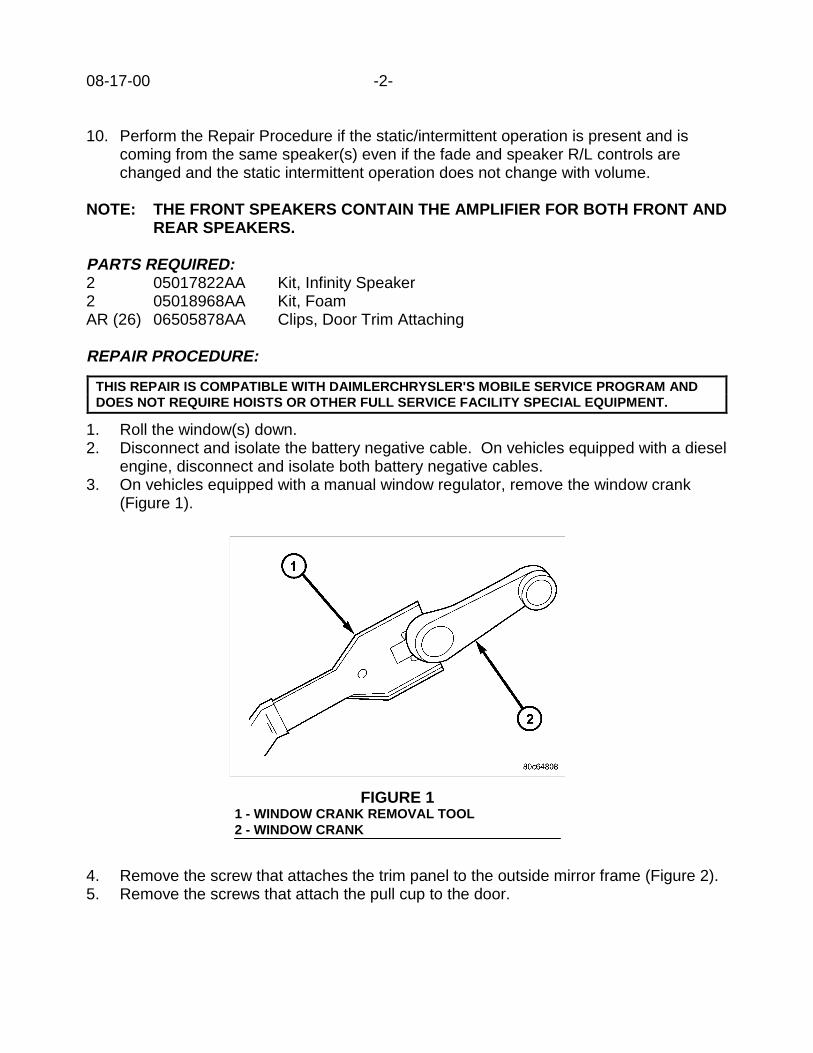
08-17-00 -2-
10. Perform the Repair Procedure if the static/intermittent operation is present and iscoming from the same speaker(s) even if the fade and speaker R/L controls arechanged and the static intermittent operation does not change with volume.
NOTE: THE FRONT SPEAKERS CONTAIN THE AMPLIFIER FOR BOTH FRONT ANDREAR SPEAKERS.
PARTS REQUIRED:2 05017822AA Kit, Infinity Speaker2 05018968AA Kit, FoamAR (26) 06505878AA Clips, Door Trim Attaching
REPAIR PROCEDURE:
1. Roll the window(s) down.2. Disconnect and isolate the battery negative cable. On vehicles equipped with a diesel
engine, disconnect and isolate both battery negative cables.3. On vehicles equipped with a manual window regulator, remove the window crank
(Figure 1).
4. Remove the screw that attaches the trim panel to the outside mirror frame (Figure 2).5. Remove the screws that attach the pull cup to the door.
THIS REPAIR IS COMPATIBLE WITH DAIMLERCHRYSLER'S MOBILE SERVICE PROGRAM ANDDOES NOT REQUIRE HOISTS OR OTHER FULL SERVICE FACILITY SPECIAL EQUIPMENT.
FIGURE 11 - WINDOW CRANK REMOVAL TOOL2 - WINDOW CRANK

-3- 08-17-00
6. Using a trim panel removal tool such as Snap On tool A161B, disengage the trimpanel retaining clips from the door. Base models, have eleven trim panel retainingclips (clips 12 and 13 not used) and premium models have thirteen (Figure 3). It isvery important that a trim panel tool is used to separate each retaining clip fromthe door.
CAUTION: DAMAGE TO THE DOOR TRIM PANEL MAY OCCUR IF THE DOOR TRIMPANEL RETAINING CLIPS ARE SEPARATED FROM THE DOORWITHOUT USING A TRIM PANEL REMOVING TOOL. DOOR PANELSSHOULD NEVER BE REMOVED BY HAND.
FIGURE 21 - POWER MIRROR2 - SCREW3 - POWER MIRROR CONTROL4 - SCREW5 - TRIM PANEL6 - DOOR LOCK BUTTON7 - POWER WINDOW HARNESS8 - POWER MIRROR HARNESS
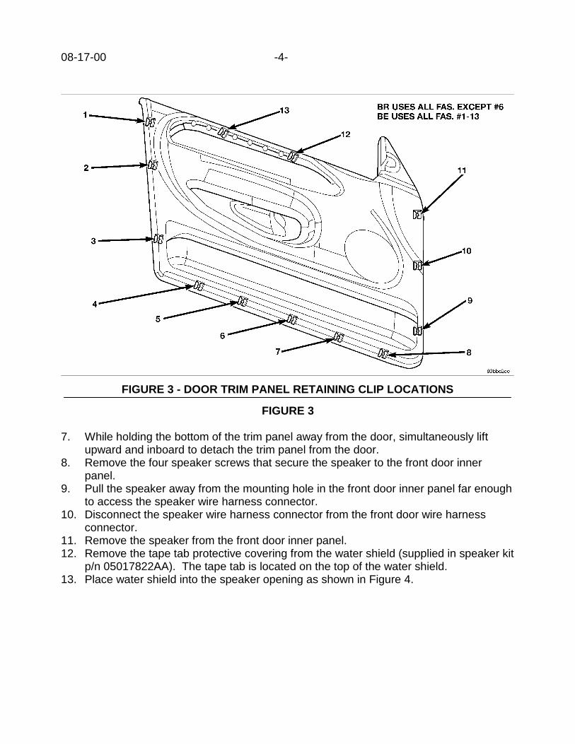
08-17-00 -4-
FIGURE 3
7. While holding the bottom of the trim panel away from the door, simultaneously liftupward and inboard to detach the trim panel from the door.
8. Remove the four speaker screws that secure the speaker to the front door innerpanel.
9. Pull the speaker away from the mounting hole in the front door inner panel far enoughto access the speaker wire harness connector.
10. Disconnect the speaker wire harness connector from the front door wire harnessconnector.
11. Remove the speaker from the front door inner panel.12. Remove the tape tab protective covering from the water shield (supplied in speaker kit
p/n 05017822AA). The tape tab is located on the top of the water shield.13. Place water shield into the speaker opening as shown in Figure 4.
FIGURE 3 - DOOR TRIM PANEL RETAINING CLIP LOCATIONS

-5- 08-17-00
14. Position the new speaker into the door opening with the amplifier facing up. Securethe speaker with the four screws.
15. Route the speaker wiring from underneath the speaker, along the side of the speakerand up to the connector as shown in Figure 4.
16. Peel the protective backing from the foam (from Foam Kit p/n 05018968AA) and placethe foam onto the inner door panel trim as shown in Figure 5.
FIGURE 4
1 - SPEAKER WIRING HARNESS2 - SPEAKER WATER SHIELD3 - INNER DOOR PANEL4 - SPEAKER
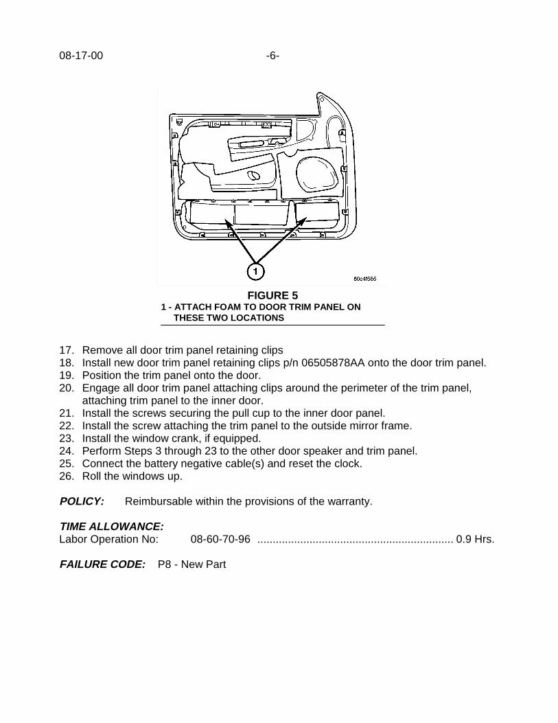
08-17-00 -6-
17. Remove all door trim panel retaining clips18. Install new door trim panel retaining clips p/n 06505878AA onto the door trim panel.19. Position the trim panel onto the door.20. Engage all door trim panel attaching clips around the perimeter of the trim panel,
attaching trim panel to the inner door.21. Install the screws securing the pull cup to the inner door panel.22. Install the screw attaching the trim panel to the outside mirror frame.23. Install the window crank, if equipped.24. Perform Steps 3 through 23 to the other door speaker and trim panel.25. Connect the battery negative cable(s) and reset the clock.26. Roll the windows up.
POLICY: Reimbursable within the provisions of the warranty.
TIME ALLOWANCE:Labor Operation No: 08-60-70-96 ................................................................ 0.9 Hrs.
FAILURE CODE: P8 - New Part
FIGURE 51 - ATTACH FOAM TO DOOR TRIM PANEL ON THESE TWO LOCATIONS

Form TSB-003 Rev. 1.08 February 3, 2000
NUMBER: 08-18-00
GROUP: Electrical
DATE: May 12, 2000
THIS BULLETIN SUPERSEDES TECHNICAL SERVICE BULLETIN 08-06-99 REV. A,DATED DECEMBER 17, 1999, WHICH SHOULD BE REMOVED FROM YOUR FILESAND NOTED IN THE 1999 TECHNICAL SERVICE BULLETIN MANUAL (PUBLICATIONNO. 81-699-00004).. ALL REVISIONS ARE HIGHLIGHTED WITH **ASTERISKS** ANDINCLUDES ADDITIONAL MODEL YEARS.
SUBJECT:Radio Interference To/From Two-Way Radio Receivers
OVERVIEW:This bulletin involves installing a RFI filter in series with the electric fuel pump motor.
MODELS:1997 - 2000 (AN) Dakota1998 **2001** (BR/BE) Ram Truck
SYMPTOM/CONDITION:Customers may complain of intermittent poor reception on their two-way radios.
NOTE: THIS CONDITION DOES NOT AFFECT THE OPERATION OF ANY AM ORFM BAND RADIO.
DISCUSSION:Radio receivers from approximately 20 MHZ to 174 MHZ may be susceptible to RadioFrequency Interference (RFI) from the fuel pump module’s motor.
The following services are within this band range of 20 MHZ to 174 MHZ:• 27 MHZ Citizen Band• Ten Meter Amateur Radio Band (28 - 29.7 MHZ)• Public Service Low Band VHF (30 - 50 MHZ)• Six Meter Amateur Radio Band (50 - 54 MHZ)• VHF Aircraft Communications Band (118 - 136 MHZ)• Two Meter Amateur Radio Band (114 - 148 MHZ)• Public Service High Band (148 - 174 MHZ)
DIAGNOSIS:Turn the ignition key to the RUN position. Operate the two-way radio and monitor forRFI/static/poor reception. If RFI is present with the ignition key in the RUN position, RFI isbeing emitted from something other than the fuel pump module’s motor. Start the engineand monitor for RFI. If RFI is identified only while the engine is running, perform thefollowing Repair Procedure.
This bulletin is supplied as technical information only and is not an authorization for repair. No part of this publication may be reproduced, stored in a retrieval system, ortransmitted, in any form or by any means, electronic, mechanical, photocopying, recording, or otherwise, without written permission of DaimlerChrysler Corporation.
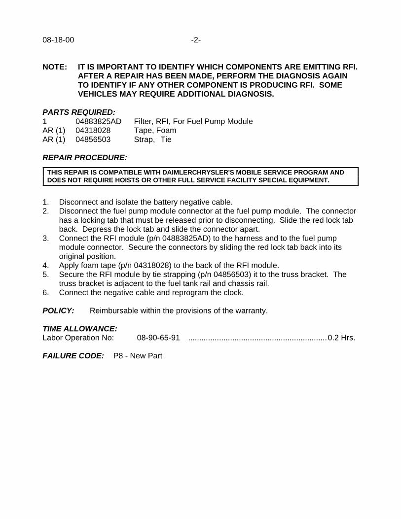
08-18-00 -2-
NOTE: IT IS IMPORTANT TO IDENTIFY WHICH COMPONENTS ARE EMITTING RFI.AFTER A REPAIR HAS BEEN MADE, PERFORM THE DIAGNOSIS AGAINTO IDENTIFY IF ANY OTHER COMPONENT IS PRODUCING RFI. SOMEVEHICLES MAY REQUIRE ADDITIONAL DIAGNOSIS.
PARTS REQUIRED:1 04883825AD Filter, RFI, For Fuel Pump ModuleAR (1) 04318028 Tape, FoamAR (1) 04856503 Strap, Tie
REPAIR PROCEDURE:
1. Disconnect and isolate the battery negative cable.2. Disconnect the fuel pump module connector at the fuel pump module. The connector
has a locking tab that must be released prior to disconnecting. Slide the red lock tabback. Depress the lock tab and slide the connector apart.
3. Connect the RFI module (p/n 04883825AD) to the harness and to the fuel pumpmodule connector. Secure the connectors by sliding the red lock tab back into itsoriginal position.
4. Apply foam tape (p/n 04318028) to the back of the RFI module.5. Secure the RFI module by tie strapping (p/n 04856503) it to the truss bracket. The
truss bracket is adjacent to the fuel tank rail and chassis rail.6. Connect the negative cable and reprogram the clock.
POLICY: Reimbursable within the provisions of the warranty.
TIME ALLOWANCE:Labor Operation No: 08-90-65-91 ...............................................................0.2 Hrs.
FAILURE CODE: P8 - New Part
THIS REPAIR IS COMPATIBLE WITH DAIMLERCHRYSLER'S MOBILE SERVICE PROGRAM ANDDOES NOT REQUIRE HOISTS OR OTHER FULL SERVICE FACILITY SPECIAL EQUIPMENT.

Form TSB-003 Rev. 1.08 February 3, 2000
NUMBER: 08-19-00
GROUP: Electrical
DATE: May 26, 2000
SUBJECT:Garage Door Opener Transmitter Range
OVERVIEW:This bulletin involves installing a supplemental antenna to the garage door openertransmitter.
MODELS:1998 - 2000 (LH) Concorde/Intrepid/LHS/300M
SYMPTOM/CONDITION:The garage door opener located in the Overhead Travel Information System (OTIS) mayhave a range drastically less than the owners original transmitter.
DIAGNOSIS:If the customer describes a functioning garage door opener with a reduced rangecompared to the opener manufacturers transmitter, perform the Repair Procedure.
PARTS REQUIRED:1 04602316AA Antenna, Garage Door Opener
REPAIR PROCEDURE:
1. Open hood, disconnect and isolate the negative battery cable remote terminal fromthe remote battery post.
2. Remove the overhead console attaching screw.3. Remove the overhead console by pulling it straight down. Use caution not to damage
the wire harness.4. Disconnect the wire harness and remove the console.5. Tape back the existing wire loop antenna.6. Remove the four OTIS mounting screws from the overhead console and remove the
OTIS.7. Place the new antenna, p/n 04602316AA, over the two round bosses with copper side
up (Figure 1).8. Install the OTIS into the overhead console. Do Not install mounting screws at this
time.9. Peel the protective backing from the antenna (Figure 1).
This bulletin is supplied as technical information only and is not an authorization for repair. No part of this publication may be reproduced, stored in a retrieval system, ortransmitted, in any form or by any means, electronic, mechanical, photocopying, recording, or otherwise, without written permission of DaimlerChrysler Corporation.
THIS REPAIR IS COMPATIBLE WITH DAIMLERCHRYSLER'S MOBILE SERVICE PROGRAM ANDDOES NOT REQUIRE HOISTS OR OTHER FULL SERVICE FACILITY SPECIAL EQUIPMENT.
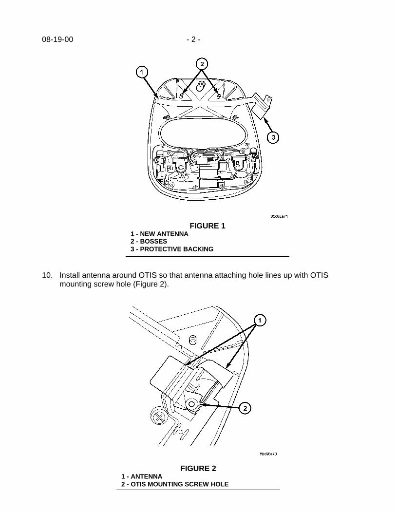
08-19-00 - 2 -
10. Install antenna around OTIS so that antenna attaching hole lines up with OTISmounting screw hole (Figure 2).
FIGURE 11 - NEW ANTENNA2 - BOSSES3 - PROTECTIVE BACKING
FIGURE 21 - ANTENNA2 - OTIS MOUNTING SCREW HOLE

- 3 - 08-19-00
11. Attach the OTIS into the overhead console, using the screws removed in step 6. Oneof the screws secures the antenna.
12. Connect the wire harnesses and install the overhead console into the roof panel.13. Connect the negative battery remote terminal.
POLICY: Reimbursable within the provisions of the warranty.
TIME ALLOWANCE:Labor Operation No: 08-45-07-93 ................................................................0.2 Hrs.
FAILURE CODE: P8 - New Part


Form TSB-003 Rev. 1.07
NUMBER: 08-20-00
GROUP: Electrical
DATE: June 9, 2000
SUBJECT:Horn Inoperative Or Sound Is Weak Or Muted
OVERVIEW:This bulletin involves the replacement and reorientation of the horn.
MODELS:2000 (PL) Neon
NOTE: THIS BULLETIN APPLIES TO VEHICLES BUILT PRIOR TO JUNE 30, 1999(MDH 0630XX).
SYMPTOM/CONDITION:Due to horn orientation, water may enter the horn interior and cause damage. The hornmay not work or the customer may report that the horn sounds quieter than before.
DIAGNOSIS:Attempt to sound the horn, if the horn is inoperative or sounds muted perform the RepairProcedure.
PARTS REQUIRED:1 05018193AA Horn, Reorientation Package
The kit includes the following items:
1 Template1 Horn
If the kit received includes an instruction sheet, please disregard and follow this TechnicalService Bulletin.
EQUIPMENT REQUIRED:6.5 mm (.25 in.) Drill BitAngle Drill
REPAIR PROCEDURE:
1. Disconnect the battery negative cable.2. Remove the far right screw of the grill emblem where it attaches to the head lamp
module housing.
This bulletin is supplied as technical information only and is not an authorization for repair. No part of this publication may be reproduced, stored in a retrieval system, ortransmitted, in any form or by any means, electronic, mechanical, photocopying, recording, or otherwise, without written permission of DaimlerChrysler Corporation.
THIS REPAIR IS COMPATIBLE WITH DAIMLERCHRYSLER'S MOBILE SERVICE PROGRAM ANDDOES NOT REQUIRE HOISTS OR OTHER FULL SERVICE FACILITY SPECIAL EQUIPMENT.

08-20-00 -2-
3. Remove the two screws attaching the right headlamp module to the uppercrossmember.
4. Pull the right headlamp module out and remove the connectors.5. Remove the headlamp module from the vehicle.6. Disconnect and remove the horn. Discard the horn.7. Cut out the template provided in the kit.8. Install the template and hold it in place by inserting the horn mounting bolt in its
original position through the template. Mark the location of the new hole through thetemplate.
9. Using a 6.5-mm (.25 in.) drill bit and an angle drill, drill a hole through the sheet metalat the point marked in step 8 (Figure 1).
FIGURE 11- ANGLE DRILL2- TEMPLATE3- HORN MOUNTING BOLT4- DRILL SHOWN IN LOCATION FOR NEW ANTI-ROTATION TAB HOLE5- HEADLAMP MODULE HOUSING__________________________________________________
10. Position and install the new horn using the original bolt hole. The new hole drilled instep 9 is for the anti-rotation tab on the new horn. The horn will now be approximatelyhorizontal.
11. Install the headlamp module assembly and the grill emblem screw.12. Install the battery negative cable.

-3- 08-20-00
POLICY: Reimbursable within the provisions of the warranty.
TIME ALLOWANCE:Labor Operation No: 08-40-01-91 ...............................................................0.3 Hrs.
FAILURE CODE: P8 - New Part


Form TSB-004 Rev. 1.05
NUMBER: 08-21-00
GROUP: Electrical
DATE: June 9, 2000
SUBJECT:Antenna Mast Installation
MODELS:2000 - 2001 (PL) Neon
DISCUSSION:The Neon antenna mast is installed at the dealership during new vehicle preparation.Recently antenna masts have been coming into the material return center with mountingsurfaces stripped. The Neon antenna should be torqued to 3.2 Nm (28 In. lbs.). With theantenna mast torqued to the proper amount (3.2 Nm ( 28 in. lbs)) there will be a slight gapbetween the mast and the base (Figure 1). The gap is there to ensure that there is nocontact between the bottom of the antenna mast and the plastic surrounding the metalinsert on the base. Do not attempt to close the gap between the antenna mast andthe base.
FIGURE 11- ANTENNA MAST2- GAP SHOULD EXIST HERE3- ANTENNA BASE__________________________________________
POLICY: Information Only
This bulletin is supplied as technical information only and is not an authorization for repair. No part of this publication may be reproduced, stored in a retrieval system, ortransmitted, in any form or by any means, electronic, mechanical, photocopying, recording, or otherwise, without written permission of DaimlerChrysler Corporation.


Form TSB-003 Rev. 1.08 February 3, 2000
NUMBER: 08-22-00 Rev A
GROUP: Electrical
DATE: Aug. 4, 2000
THIS BULLETIN SUPERSEDES TECHNICAL SERVICE BULLETIN 08-22-00, DATEDJUNE 16, 2000, WHICH SHOULD BE REMOVED FROM YOUR FILES. ALLREVISIONS ARE HIGHLIGHTED WITH **ASTERISKS** AND INCLUDE A REVISEDPART NUMBER
SUBJECT:4.7L Camshaft Position Sensor Contacts Tone Wheel
OVERVIEW:This bulletin involves the measurement and possible adjustment to the 4.7L camshaftposition sensor.
MODELS:2000 (AN) Dakota2000 (DN) Durango2000 (WJ) Grand Cherokee
NOTE: THIS BULLETIN APPLIES TO VEHICLES EQUIPPED WITH A 4.7L ENGINE.ENGINES BUILT WITH AN ENGINE DATE CODE FROM NOV. 01, 1999(JULIAN DATE OF 3059) TO NOV. 03, 1999 (JULIAN DATE OF 3079) MAY BEEFFECTED. THE ENGINE BUILD DATE CAN BE FOUND ON THE ENGINEBAR CODE LABEL, AFFIXED TO THE OIL FILL HOUSING.
SYMPTOM/CONDITION:The customer may notice a lower than expected engine performance due to a possibleloss or intermittent loss of the camshaft position sensor (CMP) signal. The loss of theCMP signal may be the result of the CMP physically contacting the tone wheel. If thisoccurs, the internal electronic circuitry of the CMP may become damaged. This conditionmay cause the illumination of the Malfunction Indicator Lamp (MIL).
The camshaft position sensor may make contact with the tone wheel because the pad onthe cylinder head, which the CMP attaches to, was over-machined.
NOTE: THE POSSIBILITY OF THIS CONDITION OCCURRING IS LIMITED TO AVERY SMALL QUANTITY OF 4.7L ENGINES. VERIFY THE ENGINE BUILDDATE.
Most of the suspect engines were inspected and repaired by the engine assembly plant. Ifrequired, a select fit shim was installed between the CMP sensor and the cylinder headpad, and around the CMP sensor attaching bolt. The shim may have been glued in placeto either the pad on the cylinder head or to the mounting tang on the camshaft positionsensor.
This bulletin is supplied as technical information only and is not an authorization for repair. No part of this publication may be reproduced, stored in a retrieval system, ortransmitted, in any form or by any means, electronic, mechanical, photocopying, recording, or otherwise, without written permission of DaimlerChrysler Corporation.
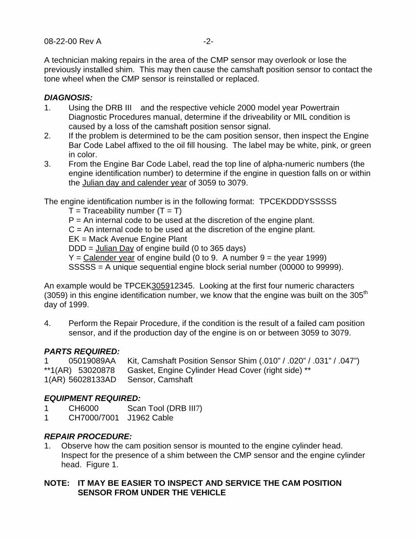
08-22-00 Rev A -2-
A technician making repairs in the area of the CMP sensor may overlook or lose thepreviously installed shim. This may then cause the camshaft position sensor to contact thetone wheel when the CMP sensor is reinstalled or replaced.
DIAGNOSIS:1. Using the DRB III and the respective vehicle 2000 model year Powertrain
Diagnostic Procedures manual, determine if the driveability or MIL condition iscaused by a loss of the camshaft position sensor signal.
2. If the problem is determined to be the cam position sensor, then inspect the EngineBar Code Label affixed to the oil fill housing. The label may be white, pink, or greenin color.
3. From the Engine Bar Code Label, read the top line of alpha-numeric numbers (theengine identification number) to determine if the engine in question falls on or withinthe Julian day and calender year of 3059 to 3079.
The engine identification number is in the following format: TPCEKDDDYSSSSST = Traceability number (T = T)P = An internal code to be used at the discretion of the engine plant.C = An internal code to be used at the discretion of the engine plant.EK = Mack Avenue Engine PlantDDD = Julian Day of engine build (0 to 365 days)Y = Calender year of engine build (0 to 9. A number 9 = the year 1999)SSSSS = A unique sequential engine block serial number (00000 to 99999).
An example would be TPCEK305912345. Looking at the first four numeric characters(3059) in this engine identification number, we know that the engine was built on the 305th
day of 1999.
4. Perform the Repair Procedure, if the condition is the result of a failed cam positionsensor, and if the production day of the engine is on or between 3059 to 3079.
PARTS REQUIRED:1 05019089AA Kit, Camshaft Position Sensor Shim (.010” / .020” / .031” / .047”)**1(AR) 53020878 Gasket, Engine Cylinder Head Cover (right side) **1(AR) 56028133AD Sensor, Camshaft
EQUIPMENT REQUIRED:1 CH6000 Scan Tool (DRB III7)1 CH7000/7001 J1962 Cable
REPAIR PROCEDURE:1. Observe how the cam position sensor is mounted to the engine cylinder head.
Inspect for the presence of a shim between the CMP sensor and the engine cylinderhead. Figure 1.
NOTE: IT MAY BE EASIER TO INSPECT AND SERVICE THE CAM POSITIONSENSOR FROM UNDER THE VEHICLE

-3- 08-22-00 Rev A
2. Disconnect the cam position sensor from its wire harness connector.3. Remove the cam position sensor from the engine. If a shim is present, it may be
glued to the CMP sensor tang, glued to the pad on the engine cylinder head, or it maybe loose. Do not lose the shim.
4. Inspect the end of the CMP sensor that is closest to the tone wheel. Note if there isany evidence of damage to the CMP sensor due to contact with the tone wheel.
5. If there is no evidence of damage to the cam position sensor, then replace the CMPsensor. If originally equipped with a select fit shim, then reuse the same shim when anew cam position sensor is installed.
FIGURE 1
1 - Cam Position Sensor (CMP)2 - Tone Wheel3 - Air gap (.030 in. +/- .010 in.)4 - Select fit shim used to adjust air gap5 - CMP sensor mounting bolt_________________________________________
6. If there is evidence of damage to the CMP sensor, due to contact with the tone wheel,then the correct amount of air gap between the CMP sensor and tone wheel must beverified.
7. Remove the right engine cylinder head cover and gasket. Refer to the 2000 modelyear WJ Service Manual – Group 9 (Engine) page 97 for additional technicalassistance.
08-22-00 Rev A -4-
8. Install a new cam position sensor to the engine cylinder head. Refer to the 2000model year WJ Service Manual – Group 8D (Electrical Ignition) page 18 for additionaltechnical assistance. Make sure the CMP sensor is full seated. The mounting boltmay be used temporarily to hold the CMP sensor in place and tight against the pad onthe engine cylinder head.
9. If necessary, use the appropriate select fit shim (p/n 05019089AA) to adjust the airgap between the cam position sensor and the tone wheel so that an air gap of 0.76mm +/- 0.25 mm (.030 in. +/- .010 in.) is achieved. Note that an air gap of 0.76 mm(.030 in.) is preferred.
10. Install and tighten the cam position sensor mounting bolt to 12 Nm (106 in. lbs.).Connect the wire harness terminal to the cam position sensor.
NOTE: BEFORE TIGHTENING THE SENSOR MOUNTING BOLT, BE SURE THESENSOR IS COMPLETELY FLUSH TO THE CYLINDER HEAD. IF THESENSOR IS NOT FLUSH, DAMAGE TO THE SENSOR MOUNTING TANGMAY RESULT.
11. Verify the air gap between the cam position sensor and the tone wheel is correct.12. Clean and inspect the engine cylinder head cover gasket and mating surfaces.
NOTE: THE CYLINDER HEAD COVER GASKET MAY BE USED AGAIN, PROVIDEDNO CUTS, TEARS, OR DEFORMATION HAS OCCURRED.
13. Install the cylinder head valve cover and gasket to the engine.14. Complete remaining assembly of engine components that may have previously been
removed during this repair procedure.
POLICY: Reimbursable within the provisions of the warranty.
TIME ALLOWANCE:Labor Operation No:
08-15-79-92 (Sensor, CMP Inspect and Replace) ……………………...……. 0.3 Hrs.08-15-79-93 (Sensor, CMP Inspect, Replace, and Verify Air Gap) ………… 1.7 Hrs.
FAILURE CODE: P8 – New Part
Form TSB-003 Rev. 1.08 February 3, 2000
NUMBER: 08-23-00
GROUP: Electrical
DATE: June 23, 2000
SUBJECT:Plastic Boot To Protect The Electrical Harness B+ End Terminal At The Generator
OVERVIEW:This bulletin involves installing a plastic protective boot and checking the generator fuse.
MODELS:1998 – 2001 (BR/BE) Ram Truck
NOTE: THIS BULLETIN APPLIES TO VEHICLES EQUIPPED WITH A 5.9L – 24VDIESEL ENGINE BUILT BEFORE ENGINE SERIAL NUMBER 56681800 WITHA DATE OF MANUFACTURE OF JANUARY 29, 2000. THIS INFORMATIONIS AVAILABLE ON THE ENGINE DATA PLATE, WHICH IS LOCATED ONTHE LEFT SIDE OF THE ENGINE, AFFIXED TO THE GEAR HOUSING.
SYMPTOM/CONDITION:While service is being performed to the engine, it may be possible for a momentaryelectrical short to occur. The electrical short may be caused when a metallic object, suchas a wrench or oil filter, comes in contact with the B+ end terminal of the generator wireharness. The B+ end terminal is bolted to the generator B+ stud (output terminal). The B+stud on the generator is protected by a plastic surround. Part of the wire harness endterminal may extend beyond the protective plastic surround for the B+ output terminal.
NOTE: IF AN ELECTRICAL SHORT HAS OCCURRED, VERIFY THAT THEGENERATOR FUSE HAS NOT OPENED (BLOWN). IF THE FUSE IS OPEN, AGRADUAL DISCHARGE OF BOTH ENGINE BATTERIES WILL OCCUR. THEGENERATOR FUSE IS LOCATED IN THE ENGINE POWER DISTRIBUTIONCENTER (PDC).
DIAGNOSIS:If a plastic protective rubber boot is not present, then perform the repair procedure.
PARTS REQUIRED:1 04487042 Boot, Generator B+ output terminal protective
REPAIR PROCEDURE:
1. Disconnect both negative battery cables from each battery.2. Remove the attaching nut used to retain the electrical wire harness end terminal to
the generator B+ stud. Remove the harness end terminal from the B+ stud on thegenerator.
This bulletin is supplied as technical information only and is not an authorization for repair. No part of this publication may be reproduced, stored in a retrieval system, ortransmitted, in any form or by any means, electronic, mechanical, photocopying, recording, or otherwise, without written permission of DaimlerChrysler Corporation.
THIS REPAIR IS COMPATIBLE WITH DAIMLERCHRYSLER'S MOBILE SERVICE PROGRAM ANDDOES NOT REQUIRE HOISTS OR OTHER FULL SERVICE FACILITY SPECIAL EQUIPMENT.

08-23-00 -2-
3. Install the protective boot (p/n 04487042) onto the wire harness. Small opening first.4. Install the electrical wire harness end terminal on to the generator B+ stud.5. Install the attaching nut onto the generator B+ stud.6. Tighten the attaching nut to 8.5 Nm (75 in. lbs.).7. Slide the large end of the protective boot over the plastic piece which surrounds the
generator B+ stud. Verify that the large end of the boot is fully seated onto the plasticsurround.
8. Install both negative battery cables to their respective battery negative terminal.9. Verify that the high amperage generator fuse, located in the PDC, is in proper working
order.
POLICY: Reimbursable within the provisions of the warranty.
TIME ALLOWANCE:Labor Operation No: 08-05-01-96 ............................................................... 0.2 Hrs.
FAILURE CODE: P8 – New Part

Form TSB-004 Rev. 1.05
NUMBER: 08-24-00
GROUP: Electrical
DATE: Sept. 8, 2000
SUBJECT:Engine Cranks But Does Not Start Or Starts And Stalls
MODELS:1998 - 2001 (AB) Ram Van/Wagon1997 - 2000 (AN) Dakota1998 - 2001 (BR/BE) Ram Truck1998 - 2000 (DN) Durango
NOTE: THIS BULLETIN APPLIES TO VEHICLES EQUIPPED WITH A VEHICLETHEFT ALARM (VTA) SYSTEM (SALES CODE LSA).
DISCUSSION:Part of “No Start” diagnosis on vehicles equipped with VTSS should include a verificationcheck of the power supply to the Central Timer Module (CTM). The CTM provides thePowertrain Control Module (PCM) with an “OK To Start” message via the CCD bus. If themessage is not received by the PCM, the PCM will not allow the engine to start. Initially,the engine may start and stall but will eventually not start at all. Most CTMs are suppliedbattery voltage through the power door lock fuse. An inspection of the fuse should be oneof the initial diagnostic checks performed. If the fuse is operational, a verification check ofthe communication system from the CTM can be performed using the DRBIII. Attempt tocommunicate to the CTM. If the CTM does not respond to the DRBIII, the DRBIII willidentify a “No Response From Central Timer Module” message. A “No Response FromCentral Timer Module” message may indicate that the CTM is not powered up. Pleaserefer to the “Communication” section of the appropriate Body Diagnostic ProceduresManual to assist in “No Start” diagnosis due to communication problems from the CTM. Inaddition, the “Vehicle Theft/Security” section will aid in the diagnosis of “No Start” issuesinvolving the VTSS system.
POLICY: Information Only
This bulletin is supplied as technical information only and is not an authorization for repair. No part of this publication may be reproduced, stored in a retrieval system, ortransmitted, in any form or by any means, electronic, mechanical, photocopying, recording, or otherwise, without written permission of DaimlerChrysler Corporation.

Form TSB-003 Rev. 1.08 February 3, 2000
NUMBER: 08-25-00
GROUP: Electrical
DATE: Sep. 15, 2000
SUBJECT:Remote Keyless Entry (RKE) Unlock Sequence - All Doors Unlock On First Button Press
MODELS:2001 (DN) Durango
NOTE: THIS BULLETIN APPLIES TO VEHICLES BUILT FROM JULY 31, 2000 (MDH0731XX) TO AUGUST 8, 2000 (MDH 0808XX) EQUIPPED WITH REMOTEKEYLESS ENTRY (SALES CODE GXR) AND NOT EQUIPPED WITH THEVEHICLE THEFT SECURITY SYSTEM (SALES CODE LSA).
DISCUSSION:A programmable feature called the “Remote Keyless Entry (RKE) Unlock Sequence” isavailable to customers which provides the opportunity to be able to program the powerdoor lock unlocking sequence when the RKE transmitter unlock button is depressed.Normally, the Central Timer Module (CTM) is programmed to have the RKE system unlockonly the driver side door when the RKE transmitter button is depressed the first time andall four doors when it is depressed a second time. Subject vehicles may have had theirCTM programmed to have the RKE system unlock all four doors when the RKEtransmitter’s unlock button is first depressed.
Customers may indicate that they would prefer to have their RKE system unlock the driverside door when the RKE transmitter button is depressed the first time and all four doorswhen it is depressed a second time. The RKE Unlock Sequence can be easily changed byusing one of the two following methods.
NOTE: CUSTOMERS HAVE THE ABILITY TO ACTIVATE THE RKE UNLOCKSEQUENCE FEATURE BY FOLLOWING THE INSTRUCTIONS IDENTIFIED INTHEIR OWNER’S MANUAL, PAGE 16.
OWNER’S MANUAL METHOD
1. Close all of the doors and fasten the seat belt.2. Place the key in the ignition and turn the key between the OFF and ON position
consecutively for a total of four times ending in the ON position (do not start theengine).
3. Within 30 seconds, press the driver’s side power door lock switch to unlock the doors.
This bulletin is supplied as technical information only and is not an authorization for repair. No part of this publication may be reproduced, stored in a retrieval system, ortransmitted, in any form or by any means, electronic, mechanical, photocopying, recording, or otherwise, without written permission of DaimlerChrysler Corporation.

08-25-00 -2-
DRB III METHOD
NOTE: THE DRB III IS REQUIRED TO PERFORM THIS REPAIR. THE DRB III MUSTBE AT VERSION 50.4 OR HIGHER WHICH IS AVAILABLE ON THE MDS2SYSTEM CIS CD2067 OR HIGHER (AVAILABLE THE WEEK OF OCTOBER2, 2000).
EQUIPMENT REQUIRED:CH6000 Scan Tool (DRB III)CH7000/7001 J1962 Cable
1. Connect the DRB III (Scan Tool) to the vehicle and switch the ignition key to “ON”.2. From the DRB III (Scan Tool) Main menu, select “Body.”3. Then select “Body Computer.”4. Select “Miscellaneous.”5. Then select “RKE Unlock Sequence.”6. The DRB III (Scan Tool) will display “RKE Unlock On First Press - Status - All
Doors.”7. Press enter to change the status to “Driver’s Door First.”
POLICY: Information Only
Form TSB-003 Rev. 1.08 February 3, 2000
NUMBER: 08-26-00
GROUP: Electrical
EFFECTIVE DATE: Sept. 29, 2000
SUBJECT:Central Timer Module Electrically “Locks-Up”
OVERVIEW:This bulletin involve replacing the Central Timer Module (CTM) with a revised part.
MODELS:2000 - 2001 (AB) Ram Van/Wagon2000 (AN) Dakota2000 - 2001 (BR/BE) Ram Truck2000 (DN) Durango
NOTE: THIS BULLETIN APPLIES TO THE ABOVE LISTED VEHICLES EQUIPPEDWITH REMOTE KEYLESS ENTRY (SALES CODE GXR). IN ADDITION, THISBULLETIN APPLIES TO VEHICLES BUILT ON OR BEFORE THEFOLLOWING BUILD DATES:
• RAM VAN/WAGONS BUILT ON OR BEFORE SEPTEMBER 14, 2000 (MDH0914XX).
• RAM TRUCKS BUILT AT THE WARREN TRUCK ASSEMBLY PLANT(11TH POSITION OF VIN = “S”) ON OR BEFORE SEPTEMBER 8, 2000(MDH 0908XX).
• RAM TRUCKS BUILT AT THE ST. LOUIS NORTH ASSEMBLY PLANT(11TH POSITION OF VIN = “J”) ON OR BEFORE AUGUST 21, 2000 (MDH0821XX).
• RAM TRUCKS BUILT AT THE SALTILLO TRUCK ASSEMBLY PLANT(11TH POSITION OF VIN = “G”) ON OR BEFORE AUGUST 31, 2000 (MDH0831XX).
• RAM TRUCKS BUILT AT THE LAGO ALBERTO TRUCK ASSEMBLYPLANT (11TH POSITION OF VIN = “M”) ON OR BEFORE SEPTEMBER 6,2000 (MDH 0906XX).
• ALL 2000 MODEL DAKOTA AND DURANGO VEHICLES.
This bulletin is supplied as technical information only and is not an authorization for repair. No part of this publication may be reproduced, stored in a retrieval system, ortransmitted, in any form or by any means, electronic, mechanical, photocopying, recording, or otherwise, without written permission of DaimlerChrysler Corporation.

08-26-00 -2-
SYMPTOM/CONDITION:Strong electromagnetic fields or devices that transmit signals in the 315 Mhz range maycause the Central Timer Module (CTM) to intermittently lock up. CTM lock-up may causea variety of customer complaints including:
• Remote Keyless Entry Malfunction• Interior Lights Will Not Come On• Intermittent Wipers Will Not Function• Chime Malfunction• Power Door Lock Malfunction• Remote Radio Switch Malfunction (if equipped)• Heated Seat Malfunction (if equipped)• Engine Will Not Start (if equipped with Vehicle Theft Alarm)• No Communication With The DRBIII (No Response from CTM)
Essentially, all CTM controlled devices will not function if the CTM locks-up.
Customers that do experience this condition may:- have their vehicle equipped with after-market accessories that emit strong
electromagnetic signals such as high output Citizen Band (CB) radios or Two-Wayradios.
- be equipped with transmitting devices that operate in the 315 Mhz range such asolder analog garage door openers.
- live or drive near devices that emit strong electromagnetic signals such as two-wayradio communication towers utilized by the military, law enforcement, etc.
DIAGNOSIS:If the vehicle exhibits one or more of the conditions identified under Symptom/Condition,pull fuse 13 (power door lock fuse) for one (1) minute. Re-insert fuse 13. If the condition isno longer present, perform the Repair Procedure. If the condition still exists, furtherdiagnosis is necessary, Refer to the appropriate Body Diagnostic Procedures Manual orthe service information available in MDS2 for additional information. If the customerindicates that they may have experienced one or more of the above conditions but wereable to correct the condition by removing power to the CTM (pull fuse 13 - power door lockfuse or disconnecting the battery) and the condition cannot be duplicated, perform theRepair Procedure. Due to the nature of this issue, it may be difficult to re-create thecustomer’s complaint
PARTS REQUIRED:AR (1) 56021861AK Module, Central Timer, Ram Van/WagonAR (1) 56045605AC Module, Central Timer, Dakota (Except Quad Cab)AR (1) 56021223AN Module, Central Timer, Dakota Quad Cab And DurangoAR (1) 56045448AD Module, Central Timer, Ram Truck (Without Heated Seats)AR (1) 56045999AD Module, Central Timer, Ram Truck Equipped With Heated
Seats
-3- 08-26-00
REPAIR PROCEDURE:
1. Remove the CTM. Refer to the appropriate Service Manual, Group 8E, Central TimerModule, or the service information available in MDS2, for information regarding CTMremoval procedures.
2. Install the new CTM (see Parts Required section). Refer to the appropriate ServiceManual, Group 8E, Central Timer Module, or the service information available inMDS2, for information regarding CTM installation procedures.
POLICY: Reimbursable within the provisions of the warranty.
TIME ALLOWANCE:Labor Operation No:
08-19-22-91 Replace Central Timer ModuleAB, AN, DN ................................................................................0.3 Hrs.BR/BE ........................................................................................0.2 Hrs.
FAILURE CODE: P8 - New Part
THIS REPAIR IS COMPATIBLE WITH DAIMLERCHRYSLER'S MOBILE SERVICE PROGRAM ANDDOES NOT REQUIRE HOISTS OR OTHER FULL SERVICE FACILITY SPECIAL EQUIPMENT.


NUMBER: 08–27–00
GROUP: Electrical
DATE: Sept. 29, 2000
This bulletin is supplied as technical information only and is not an authorization for repair. No part of this publication may be reproduced, stored in a retreival system,or transmitted, in any form or by any means, electronic, mechanical, photocopying, or otherwise, without written permission of DaimlerChrysler Corporation.
SUBJECT:Non-Deployed Airbag Handling Procedures
MODELS:
1990 - 1995 (AA) Spirit/Acclaim/Lebaron Sedan
1995 - 2001 (AB) Ram Van/Wagon
1990 - 1993 (AC) Dynasty/New Yorker/New Yorker Salon
1988 - 1993 (AG) Daytona
1988 - 1995 (AJ) Lebaron Coupe/Convertible
1990 (AL) Horizon/Omni
1988 - 1989 (AM) Diplomat/Gran Fury/New Yorker Fifth Avenue
1994 - 2001 (AN) Dakota
1990 - 1994 (AP) Shadow/Shadow Convertible/Sundance
1990 - 1991 (AQ) Chrysler Maserati
1991 - 1995 (AS) Town & Country/Caravan Voyager
1990 - 1993 (AY) Imperial/New Yorker Fifth Avenue
1994 - 2001 (BR) Ram Pickup
1995 - 1996 (B7) Stealth
1998 - 2001 (DN) Durango
1995 - 2000 (FJ) Avenger/Sebring/Talon
1995 - 2000 (JA) Breeze/Cirrus/Stratus
2001 (JR) Sebring Sedan/Stratus Sedan/Sebring Convertible
1996 - 2000 (JX) Sebring Convertible
1993 - 2001 (LH) Concorde/Intrepid/Vision/LHS/New Yorker/300M
1996 - 2000 (NS) Town & Country/Caravan/Voyager
1995 - 2001 (PL) Neon
1997 - 2001 (PR) Prowler
2001 (PT) PT Cruiser
2001 (RS) Town & Country/Caravan/Voyager
1996 - 2001 (SR) Viper
2001 (ST) Sebring Coupe/Stratus Coupe
1997 - 2001 (TJ) Wrangler
1999 - 2001 (WJ) Grand Cherokee

08–27–00 -2-
1995 - 2001 (XJ) Cherokee
1993 - 1998 (ZJ) Grand Cherokee/Grand Wagoneer
DISCUSSION:All damaged or faulty and non-deployed driver, passenger, or side airbag(s) or partially de-ployed 2001 JA and RS front airbags fall into one of two categories.
Non-Warranty Replacement: Dispose in a manner consistent with state, provincial, localand federal regulations.
Warranty Replacement: If the airbag is requested fro warranty return, the DIAL systemwill print a return document. Please return following the instructions in the current MoparHazardous Material Awareness Manual. If warranty material return is not required, disposeof in a manner consistent with state, provincial, local and federal regulations.
CAUTION: 2001 MODEL YEAR JR AND RS VEHICLE FRONT AIRBAGS THAT APPEARTO BE FULLY DEPLOYED MAY OR MAY NOT HAVE LIVE PYROTECHNIC MATERIALWITHIN THE AIRBAG INFLATOR. TO DETERMINE IF BOTH SQUIBS WERE USED (NOLIVE MATERIAL) DURING DEPLOYMENT, PERFORM THE FOLLOWING DIAGNOSTICS:
USING A DRB III ® READ AIRBAG DIAGNOSTIC TROUBLE CODES (DTC’S).
If the following active codes are present:
Driver Squib 1 openDriver Squib 2 open
And if the stored minutesfor both are within 15minutes of each otherboth Driver Squib 1 and2 were used.
Both Driver Squib 1 and2 were used
Driver Squib 1 openDriver Squib 2 open
And if the stored minutesfor Driver Squib 2 openis greater than the storedminutes for Driver Squib1 by 15 minutes or more.
Driver Squib 1 was usedDriver Squib 2 is alive
Driver Squib 1 openDriver Squib 2 open
And if the stored minutesfor Driver Squib 1 openis greater than the storedminutes for Driver Squib2 by 15 minutes or more.
Driver Squib 1 is aliveDriver Squib 2was used
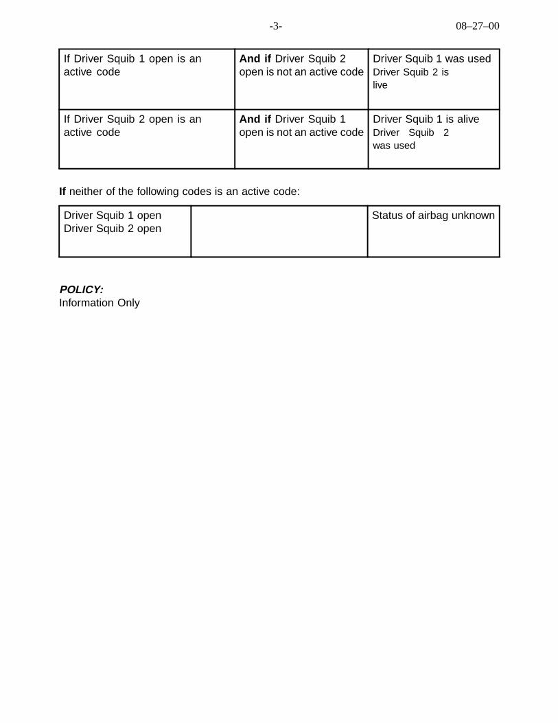
-3- 08–27–00
If Driver Squib 1 open is anactive code
And if Driver Squib 2open is not an active code
Driver Squib 1 was usedDriver Squib 2 islive
If Driver Squib 2 open is anactive code
And if Driver Squib 1open is not an active code
Driver Squib 1 is aliveDriver Squib 2was used
If neither of the following codes is an active code:
Driver Squib 1 openDriver Squib 2 open
Status of airbag unknown
POLICY:Information Only

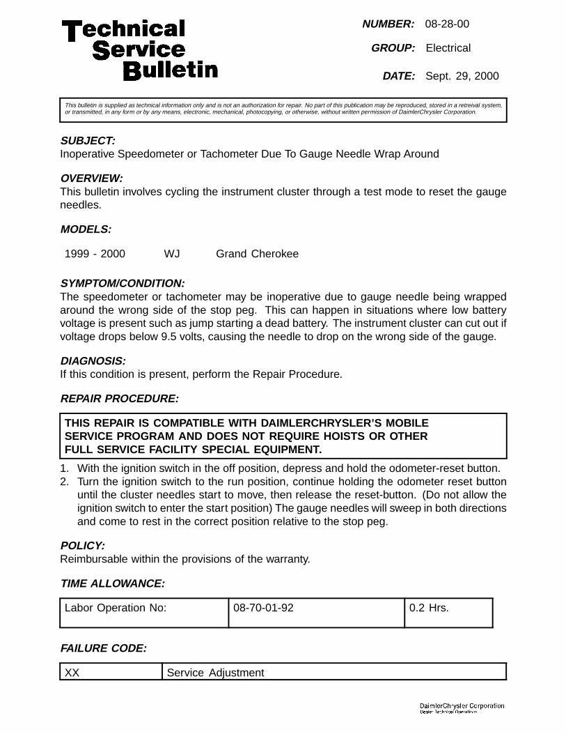
NUMBER: 08-28-00
GROUP: Electrical
DATE: Sept. 29, 2000
This bulletin is supplied as technical information only and is not an authorization for repair. No part of this publication may be reproduced, stored in a retreival system,or transmitted, in any form or by any means, electronic, mechanical, photocopying, or otherwise, without written permission of DaimlerChrysler Corporation.
SUBJECT:Inoperative Speedometer or Tachometer Due To Gauge Needle Wrap Around
OVERVIEW:This bulletin involves cycling the instrument cluster through a test mode to reset the gaugeneedles.
MODELS:
1999 - 2000 WJ Grand Cherokee
SYMPTOM/CONDITION:The speedometer or tachometer may be inoperative due to gauge needle being wrappedaround the wrong side of the stop peg. This can happen in situations where low batteryvoltage is present such as jump starting a dead battery. The instrument cluster can cut out ifvoltage drops below 9.5 volts, causing the needle to drop on the wrong side of the gauge.
DIAGNOSIS:If this condition is present, perform the Repair Procedure.
REPAIR PROCEDURE:
THIS REPAIR IS COMPATIBLE WITH DAIMLERCHRYSLER’S MOBILESERVICE PROGRAM AND DOES NOT REQUIRE HOISTS OR OTHERFULL SERVICE FACILITY SPECIAL EQUIPMENT.
1. With the ignition switch in the off position, depress and hold the odometer-reset button.2. Turn the ignition switch to the run position, continue holding the odometer reset button
until the cluster needles start to move, then release the reset-button. (Do not allow theignition switch to enter the start position) The gauge needles will sweep in both directionsand come to rest in the correct position relative to the stop peg.
POLICY:Reimbursable within the provisions of the warranty.
TIME ALLOWANCE:
Labor Operation No: 08-70-01-92 0.2 Hrs.
FAILURE CODE:
XX Service Adjustment


NUMBER: 08-029-00
GROUP: Electrical
DATE: Oct. 6, 2000
This bulletin is supplied as technical information only and is not an authorization for repair. No part of this publication may be reproduced, stored in a retreival system,or transmitted, in any form or by any means, electronic, mechanical, photocopying, or otherwise, without written permission of DaimlerChrysler Corporation.
SUBJECT:Minivan Electrical System Information
MODELS:
2001 (RS) Town & Country/ Caravan/Voyager
2001 (RG) Chrysler Voyager (International Makets)
DISCUSSION:This bulletin provides information related to the electrical system to clarify systemoperation/features/Diagnostic Trouble Codes (DTC’s) that could be confusing totechnicians that are unfamiliar with 2001 Minivans.
INTEGRATED POWER MODULE (IPM) , previously known as the Power DistributionCenter (PDC), is located next to the battery and has the following unique features:Ignition Off Draw (IOD) Fuse Location - the IOD fuse is located in the IPM (Fig. 1)and must be installed prior to delivering the vehicle to the customer.
Changeable Power Feed To The Left Rear C-Pillar And Removable Center Console12 Volt Power Outlets - C-pillar and removable center console (when positionedbetween the Quad seats) 12 volt power outlets can be changed from ignition feed tobattery feed by changing the positioning of the fuse as shown in (Fig. 1). Also note,access to the removable center console 12 volt power outlet may be difficult unlessthe cell phone holder is temporarily removed from the forward lid.
Fig. 1 INTEGRATED POWER MODULE
1 - THE POSITION OF THIS FUSE CAN BE CHANGED TO PROVIDE EITHER IGNITION FEED OR BATTERY FEED
2 - SHIPPING STORAGE POSITION FOR IOD FUSE
3 - INSTALL IOD FUSE IN THIS POSITION PRIOR TO DELIVERY

08-029-00 -2-
DIAGNOSTIC TROUBLE CODES (DTC’s) THAT COULD BE PRESENT:
The following DTC’s may be set if certain features are operated while the IgnitionOff Draw (IOD) fuse is removed. These DTC’s should be cleared with a DRBIII®.After cycling the ignition switch recheck for DTC”s:Powertrain Control Module (PCM): P1699 No Climate Control Bus Messages(Applies to Automatic Temperature Control (ATC) vehicles).
Instrument Cluster Loss Of Communication With Any Of The following: BodyControl Module (BCM), Controller Antilock Brakes (CAB), Transmission ControlModule (TCM) or Occupant Restraint Controller (ORC).
ATC Climate Control Module:Engine Status Message Missing.
Front Control Module (FCM):BCM Communication Fault (Occurs if hazard flasher is activated with IOD removed).
The following DTC’s may be present in the FCM and may re-appear when cleared even ifthere is not a fault with the circuit. Care must be taken to properly diagnose these circuits:Ignition Unlock-Run/Start Open: If the Brake Transmission Shifter Interlock(BTSI) feature functions normally this circuit is most likely functioning normally.This issue will be corrected with a future software release.
Side Air Bag Control Module Run Start Driver Over Current: If the technician cancommunicate with the side modules with a DRBIII® this circuit is most likely functioningnormally. This issue will be fixed with a future FCM hardware change.
Body Control Module (BCM):The following DTC’s may appear when the battery is being serviced or thepositive battery cable terminal is disconnected for service reasons. Care mustbe taken to properly diagnose these circuits:• IOD Wake-up Output Open or Short Circuit• VTA Lamp Output Open or Short Circuit• Left Turn Signal Indicator Output Open or Short Circuit• Right Turn Signal Indicator Output Open or Short Circuit
When the positive battery cable is disconnected, the BCM will log the above DTC’sas active. Once the battery cable has been re-connected and tightened, the aboveDTC’s become historical and should be cleared with a DRBIII®.
THE FOLLOWING DTC’S CAN BE SET BY NORMAL OPERATION:Power Sliding Door Control Module and Power Lift Gate Control Module:Faults that can be set with normal obstacle detection:• Incomplete Power Open: Overcurrent• Incomplete Power Close: Overcurrent

-3- 08-029-00
Power Sliding Door Control Module:The following DTC’s can be set because of little or no PLG “Popoff”:• Incomplete Latch Cinch Overcurrent• Incomplete Latch Release Overcurrent
The following DTC’s can be set because of PLG non-engagement orsomething blocking the lift gate:• Incomplete Power Close Missing Hall Signal• Incomplete Power Close: Full Open Switch Failure
The following DTC’s can be set because someone activates the PLG outsidehandle switch while the PLG is ajar:• Incomplete Power Open Latch Failure• Incomplete Power Close Latch Failure• Incomplete Latch Cinch Pawl Switch Failure• Incomplete Latch Cinch Ratchet Switch Failure• Incomplete Latch Release Pawl Switch Failure• Incomplete Latch Release Ratchet Switch Failure• Incomplete Latch Cinch No Current• Incomplete Latch Release No Current
HEADLAMP OPTICAL HORN:The headlamp optical horn will only function when the ignition key is in theaccessory, unlock, run, or start positions.
BODY CONTROL MODULE (BCM) - FRONT CONTROL MODULE (FCM) -POWER SLIDING DOOR (PSD), POWER LIFT GATE (PLG), SIDE AIRBAGAND SPEAKER CONNECTORS TROUBLESHOOTING:Do not insert a probe into the 1.00 mm terminals used in the BCM, IPM, SAB,or speaker connectors because this can damage the inner contacts. The visiblehood is an integral part of the terminal and should be used for continuity checkingwithout entering the inside of the terminal (Fig. 2).
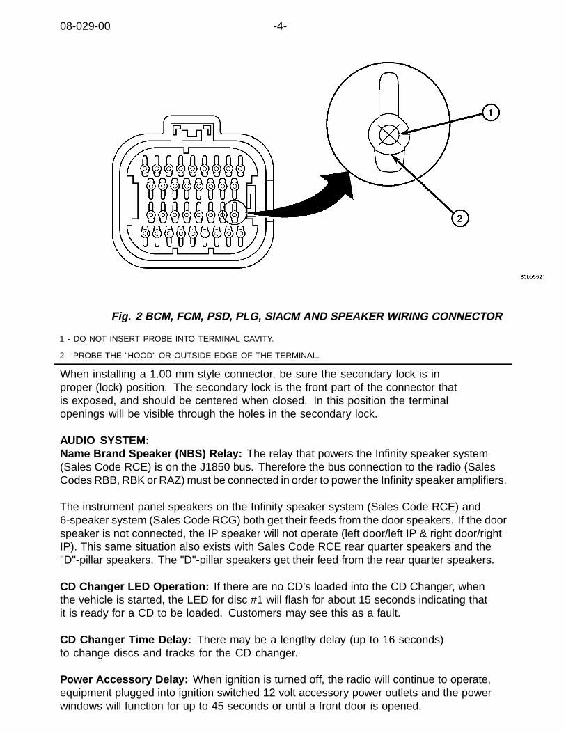
08-029-00 -4-
Fig. 2 BCM, FCM, PSD, PLG, SIACM AND SPEAKER WIRING CONNECTOR
1 - DO NOT INSERT PROBE INTO TERMINAL CAVITY.
2 - PROBE THE "HOOD" OR OUTSIDE EDGE OF THE TERMINAL.
When installing a 1.00 mm style connector, be sure the secondary lock is inproper (lock) position. The secondary lock is the front part of the connector thatis exposed, and should be centered when closed. In this position the terminalopenings will be visible through the holes in the secondary lock.
AUDIO SYSTEM:Name Brand Speaker (NBS) Relay: The relay that powers the Infinity speaker system(Sales Code RCE) is on the J1850 bus. Therefore the bus connection to the radio (SalesCodes RBB, RBK or RAZ) must be connected in order to power the Infinity speaker amplifiers.
The instrument panel speakers on the Infinity speaker system (Sales Code RCE) and6-speaker system (Sales Code RCG) both get their feeds from the door speakers. If the doorspeaker is not connected, the IP speaker will not operate (left door/left IP & right door/rightIP). This same situation also exists with Sales Code RCE rear quarter speakers and the"D"-pillar speakers. The "D"-pillar speakers get their feed from the rear quarter speakers.
CD Changer LED Operation: If there are no CD’s loaded into the CD Changer, whenthe vehicle is started, the LED for disc #1 will flash for about 15 seconds indicating thatit is ready for a CD to be loaded. Customers may see this as a fault.
CD Changer Time Delay: There may be a lengthy delay (up to 16 seconds)to change discs and tracks for the CD changer.
Power Accessory Delay: When ignition is turned off, the radio will continue to operate,equipment plugged into ignition switched 12 volt accessory power outlets and the powerwindows will function for up to 45 seconds or until a front door is opened.
-5- 08-029-00
OVERHEAD CONSOLE:An open circuit or no connection in the ambient temperature sensor circuit willcause the overhead console display to read -40F , and 130F will be displayedfor a short in the ambient temperature sensor circuit.
Overhead Console Display Modules: The RS minivans have three possible overheadconsole display modules, a compass/temperature, a compass/temperature with tripcomputer and universal garage door opener and an Electronic Vehicle InformationCenter (EVIC) and universal garage door. Vehicle operators with vehicles equippedwith a compass/temperature display may wish to purchase a compass/temperaturewith trip computer and universal garage door opener, no modifications to thevehicle are required to install the higher level module.
EVIC Personalization Menu: RS minivans equipped with EVIC have personalizationmenus similar to (WJ) Grand Cherokee. The customer can program features ofhis/her vehicle, using the EVIC, for their personal preference. This may be confusingto some. The owner’s manual explains operation features clearly.
POWER SLIDING DOOR (PSD) AND POWER LIFT GATE OPERATION (PLG):The Owner Manual and Glove Box Video descriptions of operation of the both the PSDand PLG are very clear and should be used as an additional reference. The followingcustomer complaints may be attributed to normal vehicle operation:
PSD And PLG Inoperative From Remote Keyless Entry (RKE) Key Fob SwitchOr Overhead Console Switch: Make sure the, vehicle is in Park or Neutral, vehiclespeed is zero and the doors or lift gate are fully opened or fully closed. Additionally apower sliding door must be unlocked for its overhead console switch to function andALL doors must be power unlocked for the overhead console switch for the power liftgate or the release handle in the lift gate light bar to function.
PSD Inoperative From “B”-Pillar Switch: Make sure the doors are unlocked, vehicle is inPark or Neutral, vehicle speed is zero and the sliding door is fully opened or fully closed.Also make sure the sliding door child safety lock switch(s) located on the rear shut faceof the sliding doors and the lockout switch in the overhead console are not activated.The lockout switch in the overhead console only affects “B”-pillar switches.
PSD & PLG Reversal When An RKE, “B”-Pillar Or Overhead Console SwitchIs Actuated: PSD & PLG will not reverse to CLOSING when the RKE, : “B”-Pillaror Overhead Console switch is actuated during a power OPEN cycle. PSD & PLGwill reverse to OPENING when the RKE, “B”-Pillar or Overhead Console switch isactuated during a power CLOSE cycle. This is normal operation.
REMOTE KEYLESS ENTRY (RKE):Key Fob Functions: Three button RKE transmitters are provided with vehicle NOTequipped with a PSD. Six button transmitters are provided on vehicles equipped with at leastone power sliding door. For non-power applications, the left sliding door button unlocks theleft side doors. The lift gate button unlocks the lift gate for approximately 30 seconds. Thesedifferences are explained in the Owner Manual and the pink instruction card on the tilt lever.

08-029-00 -6-
Button Delay Feature On Key Fob: Approximately a one-third second delay has beenimplemented on the left, right, lift gate and panic buttons to help prevent accidental actuation.The delay feature can be disabled (except for panic) with the following key fob button presssequence: Press the Unlock button for 5 to 10 seconds; while the Unlock button is pressed(after 5 seconds) press the Lift Gate button; release both buttons. When the Button Delay isturned off, the system will respond immediately to the press of a button (this may result inunwanted activations of a powered feature or leaving the vehicle in an unsecured state. TheButton Delay feature can be reactivated by repeating the key fob button press sequence.
Memory Seat, Mirror and Radio Station Presets Recall: The memory recall featuredoes not always work when the vehicle is unlocked with an RKE key fob button. Only theunlock button on the RKE key fob will activate the memory recall feature (assuming theRKE key fob has already been successfully linked / programmed to the memory system bythe customer). If the left sliding door key fob button was pressed to unlock the left side ofthe vehicle and open the sliding door, the memory recall feature is not activated.
VEHICLE THEFT ALARM (VTA):VTA Indicator Lamp: During the time the system is arming itself the VTA lampwill flash (approximately 16 seconds), a steadily lit VTA lamp indicates the hoodis not secure or there is a DTC in the system.
VTA Disarming: The VTA cannot be disarmed with the lift gate key cylinder.
Please refer to the vehicle Owner Manual for detailed description of operationfor any features the vehicle may be equipped with.
POLICY:Information Only

NUMBER: 08–030–0
GROUP: Electrical
DATE: Oct. 13, 2000
This bulletin is supplied as technical information only and is not an authorization for repair. No part of this publication may be reproduced, stored in a retreival system,or transmitted, in any form or by any means, electronic, mechanical, photocopying, or otherwise, without written permission of DaimlerChrysler Corporation.
SUBJECT:Instrument Cluster Illumination Inoperative And/Or Antilock Brake System Lamp Illuminated
OVERVIEW:This bulletin involves replacing the rear Automatic Temperature Control (ATC) assembly.
MODELS:
2001 (RS) Town & Country/Caravan
2001 (RG) Chrysler Voyager (International Markets)
NOTE: THIS BULLETIN APPLIES TO VEHICLES EQUIPPED WITH ATC (SALES CODEHAH).
SYMPTOM/CONDITION:Instrument cluster, overhead console display, HVAC control and radio buttons do not illumi-nate when he headlamps are turned on and/or the Antilock Brake System (ABS) lamp is ON,the overhead console display and HVAC are inoperative.
DIAGNOSIS/REPAIR PROCEDURES:1. Connect a Scan Tool (DRBIII®) to the diagnostic connector at the bottom left side of the in-
strument panel and read Body Control Module (BCM) Diagnostic Trouble Codes (DTC’s).2. If Panel Dimming Output Short DTC or Ignition Run Output Short DTC are present, re-
move the rear ATC control assembly from the headliner and disconnect the wiring con-nector.
3. Clear BCM DTC’s.4. Turn the headlamp switch ON and turn ignition switch to RUN position and check for vari-
able dimming from the dimmer switch.5. Chec for DTC’s with the DRBIII® again. If one or both of the DTC’s do not reappear,
perform the Repair Procedure. If Panel Dimming Output Short DTC reappears, furtherdiagnosis of the radio, remote control mirror switch, instrument cluster, HVAC front unit,HVAC rear unit and headlamp switch circuits will be required. If Ignition Switch Run Out-put Short DTC reappears, further diagnosis of ignition run feed to the HVAC, ABS module,overhead console circuits and instrument panel switch bank will be required.
PARTS REQUIRED:
Qty. Part No. Description
1 05005009AC Control, Rear ATC

08–030–0 -2-
EQUIPMENT REQUIRED:
CH6000 Scan Tool (DRBIII®)
REPAIR PROCEDURE:
THIS REPAIR IS COMPATIBLE WITH DAIMLERCHRYSLER’S MOBILESERVICE PROGRAM AND DOES NOT REQUIRE HOISTS OR OTHERFULL SERVICE FACILITY SPECIAL EQUIPMENT.
1. Using the procedure outlined in the 2001 Town & Country, Caravan and Voyager ServiceManual (Publication No. 81-370-1005) beginning on page 24-30 replace the rear ATCcontrol, p/n 05005009AC.
2. Turn the headlamp switch ON and turn ignition switch to RUN position and check for vari-able dimming from the dimmer switch and verify the DTC’s do not reappear.
POLICY:Reimbursable within the provisions of the warranty.
TIME ALLOWANCE:
Labor OperationNo:
24-75-16-90 0.2 Hrs
FAILURE CODE:
P8 New Part

NUMBER: 08-031-00
GROUP: Electrical
DATE: Oct. 20, 2000
This bulletin is supplied as technical information only and is not an authorization for repair. No part of this publication may be reproduced, stored in a retreival system,or transmitted, in any form or by any means, electronic, mechanical, photocopying, or otherwise, without written permission of DaimlerChrysler Corporation.
THIS BULLETIN SUPERSEDES TECHNICAL SERVICE BULLETIN 08–46–98 REV. A,DATED DECEMBER 4, 1998, WHICH SHOULD BE REMOVED FROM YOUR FILES ANDNOTED IN THE 1998 TECHNICAL SERVICE BULLETIN MANUAL (PUBLICATION NO.81–699–99003), AND TECHNICAL SERVICE BULLETIN 08–40–99, DATED DECEMBER3, 1999, WHICH SHOULD BE REMOVED FROM YOUR FILES AND NOTED IN THE 1999TECHNICAL SERVICE BULLETIN MANUAL (PUBLICATION NO. 81–699–00004). ALLREVISIONS ARE HIGHLIGHTED WITH **ASTERISKS** AND INCLUDE MODEL YEAR,DIAGNOSIS, AND REPAIR PROCEDURE.
SUBJECT:Window Sticks In The Up Position
OVERVIEW:This bulletin involves diagnosing a stuck window and repairing as necessary.
MODELS:
1998 - **2001** (LH) Concorde/Intrepid/LHS/300M
NOTE: THIS BULLETIN APPLIES AS FOLLOWS: FOR VEHICLES BUILT BEFORE OC-TOBER 1, 1999 (MDH 1001XX), REPLACE REGULATOR AND MOTOR AS REQUIRED(SEE DIAGNOSIS). FOR VEHICLES BUILT AFTER OCTOBER 1, 1999 (MDH 1001XX),REPLACE THE MOTOR ONLY AS REQUIRED (SEE DIAGNOSIS).
SYMPTOM/CONDITION:Window sticks in the up position. Condition may be intermittent.
DIAGNOSIS:If condition can be verified **and battery voltage is present, insert a trim stick or credit cardbetween the glass and inside glass run seal. Run the trim stick or credit card along theperimeter of the window. If the window is no longer stuck, replace the glass run seal**. Ifthe window is still stuck in the up position, perform the Repair Procedure. If voltage is notpresent at the window motor, test wiring and window switch and repair as necessary.
PARTS REQUIRED:
Qty. Part No. Description
AR(1) 04574092AN Regulator/Motor Assembly, Right Front
AR(1) 04574093AN Regulator/Motor Assembly, Left Front
AR(1) 04574100AL Regulator/Motor Assembly, Right Rear
AR(1) 04574101AL Regulator/Motor Assembly, Left Rear

08-031-00 -2-
AR(2) 05012544AD Motor, Window, Right
AR(2) 05012545AD Motor, Window, Left
AR 06504014 Clip, Door Panel Attaching, White, 2 requiredEach Front/Rear
AR 06503204 Clip, Door Panel Attaching, Green, 1 Required Each Rear
NOTE: LH VEHICLE DOOR TRIM PANEL CLIPS ARE NOT REUSABLE. ANYTIME ADOOR TRIM PANEL IS REMOVED THE CLIPS MUST BE REPLACED.
REPAIR PROCEDURE:
THIS REPAIR IS COMPATIBLE WITH DAIMLERCHRYSLER’S MOBILESERVICE PROGRAM AND DOES NOT REQUIRE HOISTS OR OTHERFULL SERVICE FACILITY SPECIAL EQUIPMENT.
1. Remove flag cover or speaker (front door only), door trim panel, watershield as necessary,and pull cup support bracket.
NOTE: THE FOUR SPEAKER/COVER FASTENERS ARE UNIQUE AND SHOULD NOTBE MIXED WITH THE TRIM PANEL FASTENERS.
2. Replace the (2) white clips on the trim panel with p/n 06504014.3. Replace the (1) green clip on the trim panel with p/n 06503204 (rear doors).4. Remove nuts attaching glass to lift channel and slide glass from regulator lift channel.5. Slide glass up into window frame, and support the window frame with a wood block on
the door reinforcement.6. Disconnect the wiring harness from the motor.7. Loosen bolts attaching regulator support brace to door panel.8. Loosen screw and bolt heads from keyhole slots in door panel.9. Remove bolts attaching regulator to door panel.10. Slide regulator rearward and rotate forward end of roller channel through access hole in
door panel.11. Remove regulator from door panel.12. If vehicle was built before October 1, 1999 (MDH 1001XX) go to step # 16. If vehicle was
built after October 1, 1999 (MDH 1001XX) secure the sector gear and mounting plate witha “C” clamp or similar clamping tool. This will prevent a sudden and forceful movementof the regulator when the motor is removed.
13. Remove three mounting screws that hold the motor gearbox to the regulator.14. Remove the motor from the regulator.15. Reverse steps to install motor to regulator.16. Reverse steps to install revised regulator/motor assembly into vehicle.
NOTE: TO ADJUST GLASS CORRECTLY, SQUARE GLASS IN OPENING BY PULLINGREARWARD AGAINST “B” PILLAR GLASS RUN AND PUSH DOWN ON THE EQUAL-IZER CHANNEL WITH ENOUGH FORCE (2 LB. MAX) TO TAKE OUT ANY LOOSENESSIN SYSTEM AND TIGHTEN FASTENER. DO NOT OVER ADJUST.
17. Functionally check regulator and door accessories.18. Repeat procedure on other windows as necessary.

-3- 08-031-00
POLICY:Reimbursable within the provisions of the warranty.
TIME ALLOWANCE:
Labor Operation No: Description Amount
08-52-20-90/91 Motor, Window Lift, Replace Front Right or Left 0.7 Hrs.
08-52-20-92/93 Motor, Window Lift, Replace Rear Right or Left 0.7 Hrs.
23-34-10-96/97 Regulator, Door Glass, Replace FrontRight or Left
0.5 Hrs.
23-34-11-98/99 Regulator, Door Glass, Replace Right or Left 0.5 Hrs.
23-33-20-92 Run, Door Glass, Replace Front Each 0.8 Hrs.
23-33-20-93 Run, Door Glass, Replace Rear Each 0.7 Hrs.
FAILURE CODE:
P8 New Part

NUMBER: 08-032-00 REV. A
GROUP: Electrical
DATE: Dec. 29, 2000
This bulletin is supplied as technical information only and is not an authorization for repair. No part of this publication may be reproduced, stored in a retreival system,or transmitted, in any form or by any means, electronic, mechanical, photocopying, or otherwise, without written permission of DaimlerChrysler Corporation.
THIS BULLETIN SUPERSEDES TECHNICAL SERVICE BULLETIN 08-032-00,DATED OCTOBER 20, 2000, WHICH SHOULD BE REMOVED FROM YOURFILES. THIS BULLETIN IS A COMPLETE REVISION AND NO ASTERISKSHAVE BEEN USED TO HIGHLIGHT REVISIONS
SUBJECT:"Service 4WD" Lamp Illuminated On 4X2 Vehicles
OVERVIEW:This bulletin involves installing a revised HVAC control assembly.
MODELS:
2001 (AN) Dakota
2001 (DN) Durango
NOTE: THIS BULLETIN APPLIES TO 4X2 VEHICLES BUILT BEFOREOCTOBER 13, 2000 (MDH 1013XX).
SYMPTOM/CONDITION:The “Service 4WD” lamp is illuminated even though the truck is not a 4X4 vehicle.
DIAGNOSIS:Start the engine. Once the instrument cluster bulb check has been completed,verify that the “Service 4WD” lamp is illuminated. If the “Service 4WD” lampis illuminated, perform the Repair Procedure.

08-032-00 REV. A -2-
PARTS REQUIRED:
Qty. Part No. Description
AR (1) 55055904AE Assembly, HVAC Control, Durango WithRear Heat And A/C
AR (1) 55055907AE Assembly, HVAC Control, Durango WithoutRear Heat And A/C
AR (1) 55055905AF Assembly, HVAC Control, Dakota, With A/C AndRear Window Defogger
AR (1) 55056408AE Assembly, HVAC Control, Dakota, With A/C,Without Rear Window Defogger
AR (1) 55055906AF Assembly, HVAC Control, Dakota, Without A/C,With Rear Window Defogger
AR (1) 55056409AE Assembly, HVAC Control, Dakota, Without A/C,Without Rear Window Defogger
REPAIR PROCEDURE:
THIS REPAIR IS COMPATIBLE WITH DAIMLERCHRYSLER’S MOBILESERVICE PROGRAM AND DOES NOT REQUIRE HOISTS OR OTHERFULL SERVICE FACILITY SPECIAL EQUIPMENT.
WARNING: DISABLE THE AIRBAG SYSTEM BEFORE ATTEMPTING INSTRUMENTPANEL COMPONENT SERVICE. DISCONNECT AND ISOLATE THE BATTERYNEGATIVE (GROUND) CABLE, THEN WAIT TWO MINUTES FOR THE AIRBAGSYSTEM CAPACITOR TO DISCHARGE BEFORE PERFORMING FURTHER DIAGNOSISOR SERVICE. THIS IS THE ONLY SURE WAY TO DISABLE THE AIRBAG SYSTEM.FAILURE TO TAKE THE PROPER PRECAUTIONS COULD RESULT IN ACCIDENTALAIRBAG DEPLOYMENT AND POSSIBLE PERSONAL INJURY.
1. Disconnect and isolate the battery negative cable.2. If the vehicle is equipped with an automatic transmission, turn the ignition
switch to the Unlock position, set the park brake, and place the transmissiongear selector lever in the LOW position.
3. If the vehicle is equipped with a tilt column, set the tilt steering column in its lowest position.4. Reach under the left end of the instrument panel to access and unsnap the rod end clip
on the park brake release link and disengage the link from the back of the handle (Fig. 1).

-3- 08-032-00 REV. A
Fig. 1 STEERING COLUMN OPENING COVER INSTALLATION
1 - STEERING COLUMN OPENING COVER
2 - HOOD RELEASE HANDLE
3 - SCREWS
4 - PARKING BRAKE RELEASE HANDLE
5. Remove the three screws that secure the lower edge of the steering columnopening cover to the lower instrument panel reinforcement.
6. Using a trim stick or another suitable wide flat-bladed tool, gently pry the upper edgeof the steering column opening cover just below the cluster bezel on each side of thesteering column away from the instrument panel far enough to disengage each of thesnap clip retainers from their receptacles in the instrument panel base trim (Fig. 2).
Fig. 2 STEERING COLUMN OPENING COVER
1 - INSTRUMENT PANEL TOP COVER
2 - STEERING COLUMN OPENING COVER
3 - SCREW
4 - HOOD RELEASE BRACKET
7. Remove the steering column opening cover from the instrument panel.
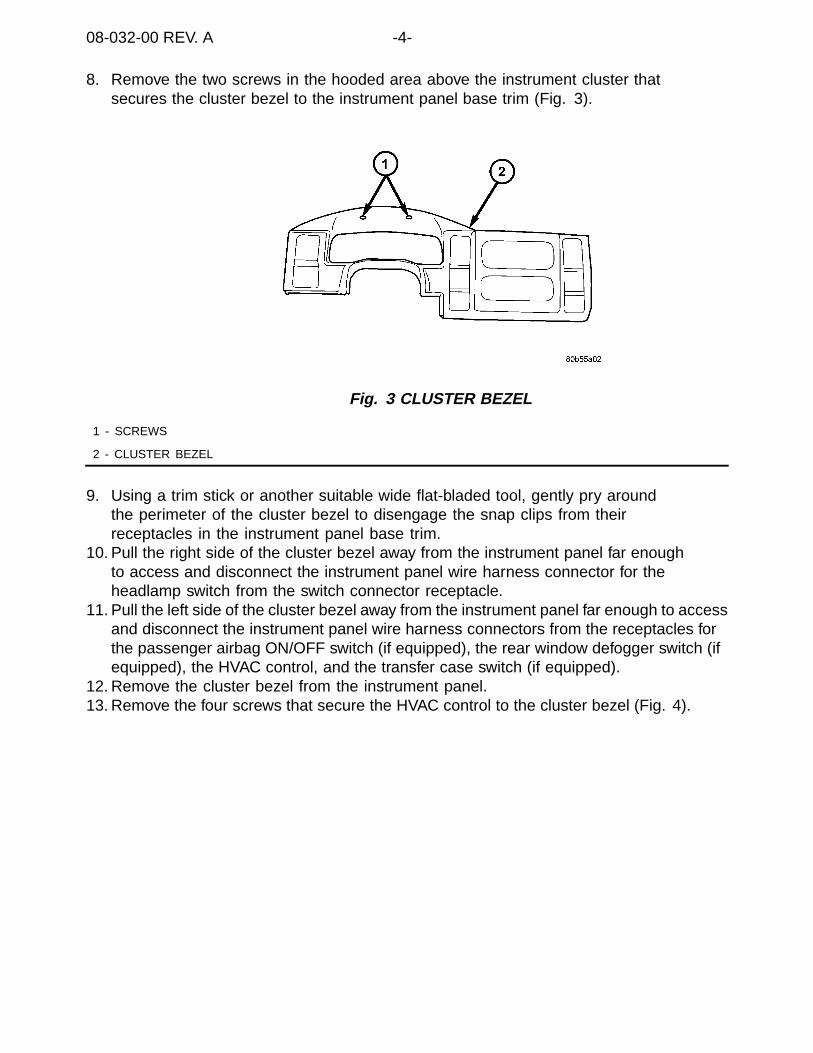
08-032-00 REV. A -4-
8. Remove the two screws in the hooded area above the instrument cluster thatsecures the cluster bezel to the instrument panel base trim (Fig. 3).
Fig. 3 CLUSTER BEZEL
1 - SCREWS
2 - CLUSTER BEZEL
9. Using a trim stick or another suitable wide flat-bladed tool, gently pry aroundthe perimeter of the cluster bezel to disengage the snap clips from theirreceptacles in the instrument panel base trim.
10. Pull the right side of the cluster bezel away from the instrument panel far enoughto access and disconnect the instrument panel wire harness connector for theheadlamp switch from the switch connector receptacle.
11. Pull the left side of the cluster bezel away from the instrument panel far enough to accessand disconnect the instrument panel wire harness connectors from the receptacles forthe passenger airbag ON/OFF switch (if equipped), the rear window defogger switch (ifequipped), the HVAC control, and the transfer case switch (if equipped).
12. Remove the cluster bezel from the instrument panel.13. Remove the four screws that secure the HVAC control to the cluster bezel (Fig. 4).

-5- 08-032-00 REV. A
Fig. 4 HVAC CONTROL
1 - HVAC CONTROL WIRING HARNESS CONNECTOR
2 - HVAC CONTROL
3 - HVAC CONTROL MOUNTING SCREW
14. Remove the HVAC control from the instrument panel.15. Position the new HVAC control (see Parts Required section) in the cluster bezel and
secure it with four screws. Tighten the screws to 2.2 N·m (17 ±3 in. lbs.)16. Position the cluster bezel to the instrument panel.17. Pull the left side of the cluster bezel away from the instrument panel far enough to
access and reconnect the instrument panel wire harness connectors to the receptaclesfor the passenger airbag on/off switch (if equipped), the rear window defogger switch (ifequipped), the HVAC control, and the transfer case switch (if equipped).
18. Pull the right side of the cluster bezel away from the instrument panel far enoughto access and reconnect the instrument panel wire harness connector for theheadlamp switch to the switch connector receptacle.
19. Align the snap clips on the cluster bezel with the receptacles inthe instrument panel base trim.
20. Using hand pressure, press firmly on the cluster bezel over each of the snap cliplocations until each snap clip is fully engaged in their receptacle.
21. Install and tighten the two screws in the hooded area above the instrumentcluster that secure the cluster bezel to the instrument panel base trim (Fig.3). Tighten the screws to 2.2 N·m (20 in. lbs.).
22. Position the steering column opening cover to the instrument panel.23. Align the snap clip retainers on the steering column opening cover with the
receptacles in the instrument panel base trim.24. Using hand pressure, press firmly on the steering column opening cover over the snap
clip locations until each of the snap clips are fully engaged in their receptacle.25. Install and tighten the three screws that secure the lower edge of the
steering column opening cover to the instrument structural support. Tightenthe screws to 2.2 N·m (20 in. lbs.).
26. Reach under the left end of the instrument panel to access and engage thepark brake release link to the back of the handle. Then snap the rod end clipover the park brake release link to secure the connection.
27. Reconnect the battery negative cable.28. On vehicles equipped with A/C, perform the A/C cool down test using the DRBIII®.
08-032-00 REV. A -6-
POLICY:Reimbursable within the provisions of the warranty.
TIME ALLOWANCE:
Labor Operation No: 24-50-10-99 0.3 Hrs.
FAILURE CODE:
P8 New Part

NUMBER: 08-033-00
GROUP: Electrical
DATE: Nov. 3, 2000
This bulletin is supplied as technical information only and is not an authorization for repair. No part of this publication may be reproduced, stored in a retreival system,or transmitted, in any form or by any means, electronic, mechanical, photocopying, or otherwise, without written permission of DaimlerChrysler Corporation.
SUBJECT:Cold CD - fault code
MODELS:
2001 (AN) Dakota
2001 (DN) Durango
2001 (JR) Sebring Sedan/Stratus Sedan
2001 (LH) Concorde/ Intrepid/LHS/300M
2001 (PL) Neon
2001 (PT) PT Cruiser
2001 (WJ) Grand Cherokee
2001 (WG) Grand Cherokee (International Markets)
DISCUSSION:A fault code may be set in the radio when performing diagnostics using the DRB III®.The code reads “Cold CD”. The fault code is not displayed to the customer and is onlydisplayed when performing diagnostics. The fault code was intended to be displayed if theCD player was operated in extreme cold temperatures. This code should be disregardedwhenever it is encountered. The fault code will be eliminated in future radios.
POLICY:Information Only


NUMBER: 08–034–00
GROUP: Electrical
DATE: November 10, 2000
This bulletin is supplied as technical information only and is not an authorization for repair. No part of this publication may be reproduced, stored in a retreival system,or transmitted, in any form or by any means, electronic, mechanical, photocopying, or otherwise, without written permission of DaimlerChrysler Corporation.
SUBJECT:PDC Relay Remover/Installation Tool
OVERVIEW:This bulletin involves use of Miller Tool Number C-4817.
MODELS:
2001 PT44 PT Cruiser
SYMPTOM/CONDITION:Relays in the Power Distribution Center (PDC) cannot be removed by hand. Attempting toremove relays with pliers may cause damage to the relay.
EQUIPMENT REQUIRED:
C-4817 Special Tool, Remover/Installer
REPAIR PROCEDURE:
THIS REPAIR IS COMPATIBLE WITH DAIMLERCHRYSLER’S MOBILESERVICE PROGRAM AND DOES NOT REQUIRE HOISTS OR OTHERFULL SERVICE FACILITY SPECIAL EQUIPMENT.
Due to the wall height of the PDC, it is necessary to use Miller Tool Number C-4817 (Fig. 1)for relay removal.
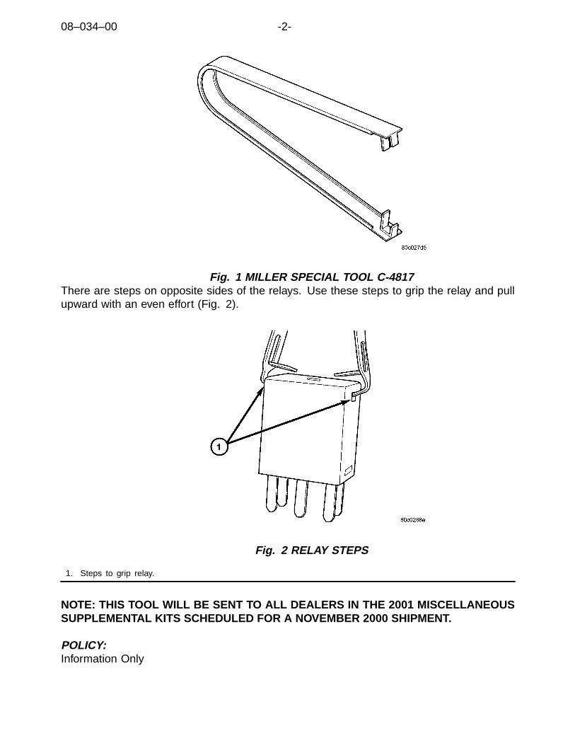
08–034–00 -2-
Fig. 1 MILLER SPECIAL TOOL C-4817There are steps on opposite sides of the relays. Use these steps to grip the relay and pullupward with an even effort (Fig. 2).
Fig. 2 RELAY STEPS
1. Steps to grip relay.
NOTE: THIS TOOL WILL BE SENT TO ALL DEALERS IN THE 2001 MISCELLANEOUSSUPPLEMENTAL KITS SCHEDULED FOR A NOVEMBER 2000 SHIPMENT.
POLICY:Information Only

NUMBER: 08-035-00
GROUP: Electrical
DATE: Nov. 10, 2000
This bulletin is supplied as technical information only and is not an authorization for repair. No part of this publication may be reproduced, stored in a retreival system,or transmitted, in any form or by any means, electronic, mechanical, photocopying, or otherwise, without written permission of DaimlerChrysler Corporation.
SUBJECT:Vehicle Surge While Speed Control Is Engaged
OVERVIEW:This bulletin involves installing a new antilock brake control module.
MODELS:
2001 (AN) Dakota
2001 (DN) Durango
NOTE: THIS BULLETIN APPLIES TO VEHICLES EQUIPPED WITH SPEED CONTROL(SALES CODE NHM) AND FOUR WHEEL ANTILOCK BRAKES (SALES CODE BGK)BUILT ON OR BEFORE THE FOLLOWING DATES:
DAKOTA STANDARD AND CLUB CAB VEHICLES BUILT ON OR BEFORESEPTEMBER 12, 2000 (MDH 0912XX).
DAKOTA QUAD CAB VEHICLES BUILT ON OR BEFORE SEPTEM-BER 5, 2000 (MDH 0905XX).
DURANGOS BUILT ON OR BEFORE AUGUST 29, 2000 (MDH 0829XX).
SYMPTOM/CONDITION:The vehicle surges while the speed control is engaged at 74 - 76 km/h (46 - 47 mph) and/orat 109 - 111 km/h (68 - 69 mph).
DIAGNOSIS/REPAIR PROCEDURES:Road test the vehicle in a location where vehicle speeds of 74 - 76 km/h (46 - 47 mph) and/or109 - 111 km/h (68 - 69 mph) can be maintained safely. Set the speed control at 74 - 76km/h (46 - 47 mph) or at 109 - 111 km/h (68 - 69 mph). If the vehicle surges, disengage thespeed control. If the vehicle still surges, further diagnosis is required. If the vehicle surgesonly while the speed control is engaged, perform the Repair Procedure.
NOTE: DUE TO THE NATURE OF THIS CONDITION, IT MAY BE DIFFICULT TO DUPLI-CATE THE SYMPTOM. IF THE CUSTOMER INDICATES THAT THE VEHICLE SURGESAT 74 - 76 KM/H (46 - 47 MPH) AND/OR AT 109 - 111 KM/H (68 - 69 MPH) ONLY WHENTHE SPEED CONTROL IS ENGAGED, PERFORM THE REPAIR PROCEDURE.

08-035-00 -2-
PARTS REQUIRED:
Qty. Part No. Description
AR (1) 05018877AD Controller, Antilock Brake, Dakota Quad Cab
AR (1) 05018808AD Controller, Antilock Brake, Dakota Standard And Club Cab
AR (1) 05018807AD Controller, Antilock Brake, Durango
NOTE: ANTILOCK BRAKE CONTROLLER AVAILABILITY IS RESTRICTED. THE STARCENTER MUST BE CONTACTED TO GET AUTHORIZATION AND TO ORDER A CON-TROLLER. THE STAR CENTER’S PHONE NUMBER IS 1-800-850-STAR (7827). WHENTHE AUTOMATED ANSWERING SYSTEM REQUESTS A GROUP SELECTION, SELECTBRAKES AND THEN SELECT THE KELSEY HAYES GROUP.
EQUIPMENT REQUIRED:
CH6000 Scan Tool (DRBIII®)CH7035 General Purpose Interface Bus (GPIB) Cable
CH7000/7001 J1962 Cable
REPAIR PROCEDURE:
THIS REPAIR IS COMPATIBLE WITH DAIMLERCHRYSLER’S MOBILESERVICE PROGRAM AND DOES NOT REQUIRE HOISTS OR OTHERFULL SERVICE FACILITY SPECIAL EQUIPMENT.
NOTE: ONCE THE ANTILOCK BRAKE CONTROL MODULE (CAB) IS REPLACED, THEREAR AXLE TYPE AND TIRE SIZE MUST BE PROGRAMED INTO THE NEW CAB.
1. Disconnect battery negative cable.2. Push the harness connector locks to release the locks,(Fig. 1) then remove the connec-
tors from the CAB.

-3- 08-035-00
Fig. 1 CAB CONNECTOR LOCKS
1 - CONNECTOR LOCK
2 - CAB
3. Disconnect the pump motor connector (Fig. 2).
Fig. 2 PUMP MOTOR CONNECTOR
1 - PUMP MOTOR
2 - PUMP CONNECTOR
4. Remove screws attaching CAB to the Hydraulic control Unit (HCU) (Fig. 3).

08-035-00 -4-
Fig. 3 CAB MOUNTING SCREWS
1 - CAB
2 - MOUNTING LOCATIONS
5. Remove the CAB.6. Place the new CAB onto the HCU (see Parts Required section).
NOTE: ENSURE THE CAB SEAL IS IN POSITION BEFORE INSTALLATION.
7. Install the mounting screws and tighten to 4-4.7 N·m (36-42 in. lbs.).8. Connect the pump motor harness.9. Connect the harnesses to the CAB and lock the connectors.10. Connect battery.
NOTE: THE NEW CAB MUST HAVE THE TIRE SIZE AND AXLE TYPE PROGRAMMEDINTO THE NEW CONTROLLER IN ORDER TO HAVE THE CONTROLLER COMMUNI-CATE THE PROPER VEHICLE SPEED. FAILURE TO PROPERLY PROGRAM THE RE-PLACEMENT CAB WILL RESULT IN A BLINKING ABS INDICATOR.
11. Inspect rear tires to determine tire sizes.12. Determine which rear axle type is used on this vehicle. Refer to the following graphics to
help in identifying axle types (Fig. 4) (Fig. 5).
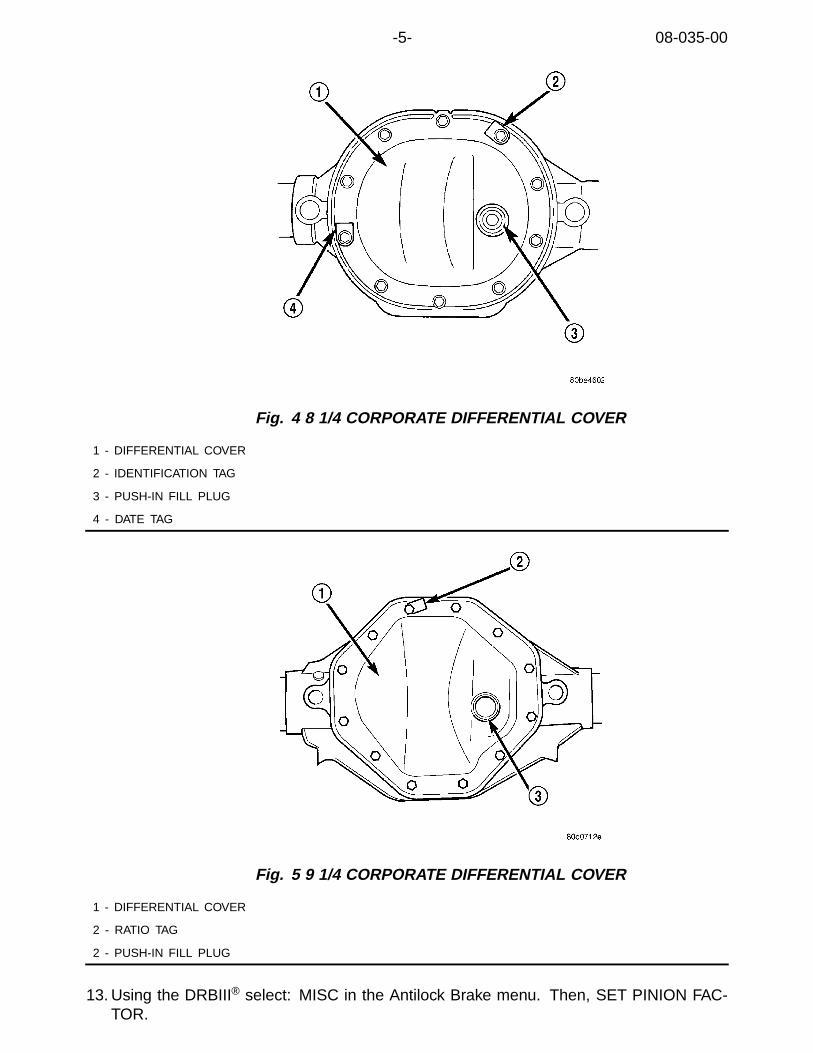
-5- 08-035-00
Fig. 4 8 1/4 CORPORATE DIFFERENTIAL COVER
1 - DIFFERENTIAL COVER
2 - IDENTIFICATION TAG
3 - PUSH-IN FILL PLUG
4 - DATE TAG
Fig. 5 9 1/4 CORPORATE DIFFERENTIAL COVER
1 - DIFFERENTIAL COVER
2 - RATIO TAG
2 - PUSH-IN FILL PLUG
13. Using the DRBIII® select: MISC in the Antilock Brake menu. Then, SET PINION FAC-TOR.

08-035-00 -6-
NOTE: THE DRBIII® MENU SCREEN CAN ONLY PROGRAM PRODUCTION SIZE TIRESTHAT WERE CERTIFIED FOR THE VEHICLE WHEN THE VEHICLE WAS MANUFAC-TURED. IF THE TIRES ON THE VEHICLE DO NOT MATCH TIRE SIZES AVAILABLE ONTHE DRBIII® MENU SCREEN, THEN THE TIRE ON THE VEHICLE WAS NEVER CERTI-FIED FOR USAGE.
14. Turn the ignition switch to the RUN position (engine not running).15. With the DRBIII®, program the correct tire size and rear axle type.16. Road test the vehicle above 48 Km/h (30 mph) for at least two minutes to ensure that the
antilock brake system functions as designed. If the ABS warning lamp illuminates duringthe road test, further diagnosis is required. Refer to the appropriate Chassis DiagnosticManual or the service information available in the MDS2.
POLICY:Reimbursable within the provisions of the warranty.
TIME ALLOWANCE:
Labor Operation No: 08-19-10-95 0.4 Hrs.
FAILURE CODE:
P8 New Part

NUMBER: 08-036-00
GROUP: Electrical
DATE: Nov. 17, 2000
This bulletin is supplied as technical information only and is not an authorization for repair. No part of this publication may be reproduced, stored in a retreival system,or transmitted, in any form or by any means, electronic, mechanical, photocopying, or otherwise, without written permission of DaimlerChrysler Corporation.
SUBJECT:Circuits Effected By Ignition Off Draw (IOD) Fuse
MODELS:
2001 (AB) Ram Van
2001 (AN/AN84) Dakota/Dakota Quad Cab
2001 (BR/BE) Ram Truck/Ram Truck Quad Cab
2001 (DN) Durango
2001 (JR/JR27) Stratus/Sebring/Sebring Convertible
2001 (LH) Concorde/Intrepid/LHS/300M
2001 (PL/P2) Neon
2001 (PT) PT Crusier
2001 (PR) Prowler
2001 (RG) Chrysler Voyager (International Markets)
2001 (RS) Town & Country/Voyager/Caravan
2001 (SR) Viper/Viper Coupe
2001 (ST) Sebring/Stratus Coupe
2001 (TJ) Wrangler
2001 (WG) Grand Cherokee (International Markets)
2001 (WJ) Grand Cherokee
2001 (XJ) Cherokee
DISCUSSION:The components/features that are disabled by the Ignition Off Draw (IOD) fuse variesfrom vehicle model to vehicle model. Below is a listing, by vehicle model, of whatcomponents/features are affected when the IOD fuse is removed.
AB:Courtesy Lamp Relay (non-Central Timer Module equipped vehicles), Dome Lamps,Glove Box Lamp, Key Chime, Power Mirrors and Underhood Lamp.
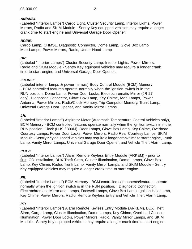
08-036-00 -2-
AN/AN84:(Labeled “Interior Lamps”) Cargo Light, Cluster Security Lamp, Interior Lights, PowerMirrors, Radio and SKIM Module - Sentry Key equipped vehicles may require a longercrank time to start engine and Universal Garage Door Opener.
BR/BE:Cargo Lamp, CHMSL, Diagnostic Connector, Dome Lamp, Glove Box Lamp,Map Lamps, Power Mirrors, Radio, Under Hood Lamp.
DN:(Labeled “Interior Lamps”) Cluster Security Lamp, Interior Lights, Power Mirrors,Radio and SKIM Module - Sentry Key equipped vehicles may require a longer cranktime to start engine and Universal Garage Door Opener.
JR/JR27:(Labeled interior lamps & power mirrors) Body Control Module (BCM) Memory- BCM controlled features operate normally when the ignition switch is in theRUN position, Dome Lamp, Power Door Locks, Electrochromatic Mirror (JR-27only), Diagnostic Connector, Glove Box Lamp, Key Chime, Map Lamps, PowerAntenna, Power Mirrors, Radio/Clock Memory, Trip Computer Memory, Trunk Lamp,Universal Garage Door Opener, and Vanity Mirror Lamps.
LH:(Labeled “Interior Lamps”) Aspirator Motor (Automatic Temperature Control Vehicles only),BCM Memory - BCM controlled features operate normally when the ignition switch is in theRUN position, Clock (LHS / 300M), Door Lamps, Glove Box Lamp, Key Chime, OverheadCourtesy Lamps, Power Door Locks, Power Mirrors, Radio Rear Courtesy Lamps, SKIMModule - Sentry Key equipped vehicles may require a longer crank time to start engine, TrunkLamp, Vanity Mirror Lamps, Universal Garage Door Opener, and Vehicle Theft Alarm Lamp.
PL/P2:(Labeled “Interior Lamps”) Alarm Remote Keyless Entry Module (ARKEM) - prior tofirst IOD installation, BUX Theft Siren, Cluster Illumination, Dome Lamps, Glove BoxLamp, Key Chime, Radio, Trunk Lamp, Vanity Mirror Lamps, and SKIM Module - SentryKey equipped vehicles may require a longer crank time to start engine.
PR:(Labeled “Interior Lamps”) BCM Memory - BCM controlled components/features operatenormally when the ignition switch is in the RUN position, , Diagnostic Connector,Electrochromatic Mirror and Lamps, Footwell Lamps, Glove Box Lamp, Ignition Halo Lamp,Key Chime, Power Mirrors, Radio, Remote Keyless Entry and Vehicle Theft Alarm Lamp.
PT:(Labeled “Interior Lamps”) Alarm Remote Keyless Entry Module (ARKEM), BUX TheftSiren, Cargo Lamp, Cluster Illumination, Dome Lamps, Key Chime, Overhead ConsoleIllumination, Power Door Locks, Power Mirrors, Radio, Vanity Mirror Lamps, and SKIMModule - Sentry Key equipped vehicles may require a longer crank time to start engine.

-3- 08-036-00
RS/RG:Automatic Temperature Control HVAC control head, BCM Memory - BCM controlledcomponents/features operate normally when the ignition switch is in the RUN position, KeyChime, Memory Seats & Mirrors, Overhead Console switches and display - operatesnormally when the ignition switch is in the RUN position, Infinity speaker amplifiers, Radio,Remote Keyless Entry, SKIM Module - Sentry Key equipped vehicles may require a longercrank time to start the engine, Thatcham security alarm module (RG only).
SR:IOD fuse is not remove for shipping. We also recommend that the fuse not be usedin service because it disables the entry system and SR-vehicle IOD is extremelylow. The following would also be disabled: Cargo Lamp (coupe), DiagnosticConnector, Dome Lamp (coupe), Ignition Halo Lamp, Illuminated mirror, Left MessageCenter, Radio, Wiper Motors and Wiper Control Module.
ST:(Labeled with musical note and dome lamp symbols, two fuses caged with yellowbracket) Audio System, Compass/Temperature Display, Dome Light, Key Chime, PowerDoor Locks, Remote Keyless Entry (RKE), Sunroof, and Trunk Light.
TJ:Courtesy Lamps, Cluster Illumination, Diagnostic Connector, Key Chime,Sound Bar, Radio and Underhood Lamp.
WJ/WG:(Labeled JB Power) Audio Amp, BCM Memory - BCM controlled components/featuresoperate normally when the ignition switch is in the RUN position Flipper Window PowerRelease, Glovebox Lamp, HEVAC module (ATC), Instrument Panel Courtesy Lamps, KeyChime, Overhead Lamps, Power Outlets (front and rear) Radio, Rear Wiper, SKIM Module -Sentry Key equipped vehicles may require a longer crank time to start engine, UnderhoodLamp, and Vehicle Theft Alarm (VTA) Set Lamp (VTA is disabled with IOD pulled).
XJ:Cluster Illumination, Interior Lighting, Key Chime, Radio, Transmission ControlModule (TCM) memory, and Underhood Lamp.
POLICY:Information Only


NUMBER: 08-037-00
GROUP: Electrical
DATE: December 8, 2000
This bulletin is supplied as technical information only and is not an authorization for repair. No part of this publication may be reproduced, stored in a retreival system,or transmitted, in any form or by any means, electronic, mechanical, photocopying, or otherwise, without written permission of DaimlerChrysler Corporation.
SUBJECT:Driver’s Air Bag Service
OVERVIEW:This bulletin involves the service of the foam rubber pads under thedrivers airbag retention clips.
MODELS:
2001 PT44 PT Cruiser
SYMPTOM/CONDITION:One or more of the factory-installed foam rubber pads, located under the driver airbagretention clips, may fall off if the airbag is removed. All required foam rubber pads mustbe in place when the airbag is installed to prevent a rattle or buzz complaint.
PARTS REQUIRED:
Qty. Part No. Description
1 5072250AA Foam Pad Kit
REPAIR PROCEDURE:
THIS REPAIR IS COMPATIBLE WITH DAIMLERCHRYSLER’S MOBILESERVICE PROGRAM AND DOES NOT REQUIRE HOISTS OR OTHERFULL SERVICE FACILITY SPECIAL EQUIPMENT.
NOTE: REFER TO THE 2001 PT CRUISER SERVICE MANUAL, USING PROCEDURESPROVIDED IN SECTION 8M, FOR DISASSEMBLY AND ASSEMBLY OF THECOMPONENTS SURROUNDING THE STEERING WHEEL. BE SURE TO FOLLOWTHE WARNING AND CAUTION INFORMATION PROVIDED IN THE SERVICEMANUAL OR UNDER THE MDS2 SERVICE INFORMATION TAB. THESE INCLUDEDISCONNECTING THE NEGATIVE BATTERY CABLE BEFORE STARTING STEERINGCOLUMN REPAIR AND WEARING SAFETY GLASSES.
1. Disassemble the driver airbag and steering wheel per Service Manual instruction.
NOTE: PRY OPEN THE DRIVER AIRBAG RETAINING CLIP USING A90 DEGREE INTERNAL SNAP RING PLIERS PER SERVICE MANUALINSTRUCTIONS TO RELEASE THE AIRBAG.
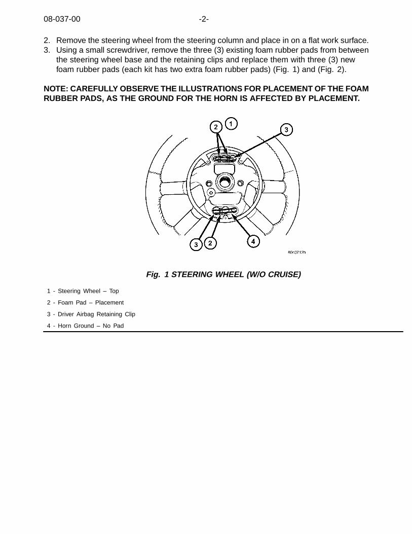
08-037-00 -2-
2. Remove the steering wheel from the steering column and place in on a flat work surface.3. Using a small screwdriver, remove the three (3) existing foam rubber pads from between
the steering wheel base and the retaining clips and replace them with three (3) newfoam rubber pads (each kit has two extra foam rubber pads) (Fig. 1) and (Fig. 2).
NOTE: CAREFULLY OBSERVE THE ILLUSTRATIONS FOR PLACEMENT OF THE FOAMRUBBER PADS, AS THE GROUND FOR THE HORN IS AFFECTED BY PLACEMENT.
Fig. 1 STEERING WHEEL (W/O CRUISE)
1 - Steering Wheel – Top
2 - Foam Pad – Placement
3 - Driver Airbag Retaining Clip
4 - Horn Ground – No Pad

-3- 08-037-00
Fig. 2 STEERING WHEEL (W/CRUISE)
1 - Steering Wheel – Top
2 - Foam Pad – Placement
3 - Driver Airbag Retaining Clip
4 - Horn Ground – No Pad
4. Continue the repair and assemble components per Service Manual instructions.
POLICY:Information Only


NUMBER: 08-038-00
GROUP: Electrical
DATE: Dec. 8, 2000
This bulletin is supplied as technical information only and is not an authorization for repair. No part of this publication may be reproduced, stored in a retreival system,or transmitted, in any form or by any means, electronic, mechanical, photocopying, or otherwise, without written permission of DaimlerChrysler Corporation.
SUBJECT:Safety Systems – Vehicle Modifications/Repair
MODELS:
2001 (AB) Ram Van/Wagon
2001 (AN) Dakota
2001 (BR/BE) Ram Pickup
2001 (DN) Durango
2001 (JR) Sebring Sedan/Stratus Sedan/Sebring Convertible
2001 (LH) Concorde/Intrepid/LHS/300M
2001 (PL) Neon
2001 (PR) Prowler
2001 (PT) PT Cruiser
2001 (RS) Town & Country/Caravan/Voyager
2001 (RG) Chrysler Voyager (International Markets)
2001 (SR) Viper
2001 (ST) Sebring Coupe/Stratus Coupe
2001 (TJ) Wrangler
2001 (WJ) Grand Cherokee
2001 (WG) Grand cherokee (International Markets)
2001 (XJ) Cherokee
DISCUSSION:Current DaimlerChrysler vehicles may contain any or all of the following safety systems:driver airbags, passenger airbags, side curtain airbags, side seat airbags, or seat beltpre-tensioners. All these systems contain multiple sophisticated sensitive electrical andmechanical components. The location and function of all safety system components mustbe determined before performing repairs; including accident, mechanical or electrical,or vehicle modifications such as adding an after-market sunroof.
WARNING: ANY INADVERTENT SAFETY SYSTEM COMPONENT OR ASSOCIATEDWIRING DAMAGE/MODIFICATION OR COMPONENT LOCATION CHANGEMAY DISABLE ANY OF THE SAFETY SYSTEMS.

08-038-00 -2-
Refer to the appropriate vehicle Service Manual to determine location and functionof all safety systems before servicing vehicle. All systems should be checked forfunctionality after the vehicle modifications/repairs are complete.
POLICY:Information Only
NUMBER: 08–039–00
GROUP: Electrical
DATE: Dec. 8, 2000
This bulletin is supplied as technical information only and is not an authorization for repair. No part of this publication may be reproduced, stored in a retreival system,or transmitted, in any form or by any means, electronic, mechanical, photocopying, or otherwise, without written permission of DaimlerChrysler Corporation.
SUBJECT:Sentry Key — Key Immobilizer Security System
MODELS:
2001 (ST) Sebring/Stratus Coupe
DISCUSSION:The Anti-theft engine immobilizer with security key is designed to significantlyreduce the possibility of vehicle theft. The system immobilizes the vehicle if aninvalid start is attempted. A valid start can only be accomplished by using a keyregistered to the vehicles electronic immobilizer system.
The immobilizer system consists of the ignition key(s), key ring antenna, immobilizer ECUand Engine Control Module (ECM) M/T or Powertrain Control Module (PCM) A/T models.The ignition key has a built in transponder. The key ring antenna is installed around theignition key cylinder. The immobilizer ECU and ECM or PCM are located within theinstrument panel. If requirements for starting the engine are not satisfied, the engine willstart and stall within a few seconds of the first invalid attempt. After the initial start andstall, the engine will not start since the fuel and ignition systems are disabled.
Three keys are provided with each vehicle. Two of the keys are “Master” ignitionkeys and the third is a valet key. The master key fits all locks, whereas the valet keyfits all locks except the glove box and trunk. If keys are lost or additional keys arerequired, they can be registered using the DRB III® and CH8425 PCMCIA card. Theimmobilizer ECU can hold up to 8 uniquely coded transponder keys of any master or valetcombination. In addition to registering keys, the DRB III® can be used to read DTC’sfor diagnostics and read the number of keys registered for a given vehicle.
NOTE: KEYS CAN ONLY BE PROGRAMMED BY USING THE DRBIII ®. THISFEATURE FOR THE D.A.R.T. IS CURRENTLY NOT AVAILABLE.
If a system failure is detected and the immobilizer ECU or an ECM/PCM requirereplacement, the only requirement is to re-register keys. If the ECM/PCM or ECUis replaced for any reason, the DRB III® may not allow key registration due tothe immobilizer ECU not recognizing the encrypted code and password from theECM/PCM. If this occurs, the following steps are required:1. Switch the Ignition key to “OFF” and remove it from the ignition cylinder.2. Remove the DRB III® from the vehicle.

08–039–00 -2-
3. Insert the ignition key and switch the ignition to “ON” for a minimum of 30 seconds.4. Switch the ignition key to “OFF” and connect the DRB III®.5. Boot the DRB III® with the PCMCIA card and follow registration procedures listed below.
PARTS REQUIRED:
Qty. Part No. Description
AR MR558768 Key, Master Sebring
AR MR530317 Key, Master Stratus
AR MR515985 Key, Valet Sebring/Stratus
EQUIPMENT REQUIRED:
CH6000 Scan Tool (DRB III®
CH8425 ST22 PCMCIA Diagnostic Card
CH7010 J1962 MMC Cable
REGISTRATION PROCEDURE:
NOTE: ALL KEYS MUST BE AVAILABLE BEFORE PROCEEDING.
1. Connect the DRB III® to the vehicle and boot (RUN MEMORY CARDPROGRAM) the PCMCIA card.
2. Switch the ignition key to the “ON” position and select SYSTEMSELECT from the main menu.
3. From the SYSTEM SELECT menu, select IMMOBILIZER.4. From the SELECT FUNCTION menu, select SPECIAL FUNCTION.5. From the SPECIAL menu, select KEY ID REGISTRATION.6. Once KEY ID REGISTRATION is selected, the DRB III® will prompt for a
password. Input 6876 to proceed with key registration.
NOTE: IF AN INCORRECT PASSWORD IS INPUT 5 TIMES, THE IMMOBILIZERECU WILL SWITCH TO UNAUTHORIZED OPERATION MODE AND PREVENTKEY REGISTRATION. THE DRB III ® WILL INDICATE THIS BY DISPLAYING“CANT EXECUTE FOR 20 MIN. DUE TO WRONG PASSWORD.
7. Follow the remaining prompts on the DRB III® to complete key registration procedures.
NOTE: IF AN ERROR OCCURS DURING KEY ID REGISTRATION, THE MESSAGE“CANT EXECUTE” WILL BE DISPLAYED. IF THE KEY HAS ALREADY BEENPROGRAMMED, “KEY ID HAS BEEN REGISTERED” WILL BE DISPLAYED.
8. Once all keys have been registered, press the NO key on the DRBIII® to exit the registration menu.
9. Switch the ignition key “OFF” for 10 seconds and then check to make sureeach key that was registered will start the vehicle.
10. If all keys start the vehicle, switch the ignition “OFF” and remove the DRB III®.

-3- 08–039–00
POLICY:Information Only


NUMBER: 08–040–00
GROUP: Electrical
DATE: Dec. 8, 2000
This bulletin is supplied as technical information only and is not an authorization for repair. No part of this publication may be reproduced, stored in a retreival system,or transmitted, in any form or by any means, electronic, mechanical, photocopying, or otherwise, without written permission of DaimlerChrysler Corporation.
SUBJECT:Motor Replacement — Power Seat Slide Adjuster
OVERVIEW:This bulletin describes new procedures for replacement of the seat motorwhich is now serviced seperately.
MODELS:
1995 - 2000 FJ Avenger/Sebring/Talon
DISCUSSION:New components and a repair procedure have been developed to replace failedseat slide motors. The process for replacing a motor as compared to a seatassembly will reduce repair time and component cost along with increasingcustomer satisfaction in the event this repair is required.
DIAGNOSIS/REPAIR PROCEDURES:Determine if the motor has failed as follows:1. Check fuses applicable to the circuit.2. Check for power (12 v) to and from the switch while operating the switch.3. Check for power (12 v) at the motor while operating the switch.If power is available at the motor and the slide motor will not function,perform the Repair Procedure.
PARTS REQUIRED:
Qty. Part No. Description
1 MR311167 Kit, Seat Slide Adjuster Motor
EQUIPMENT REQUIRED:
NPN T-20 Torx (with long extension)
NPN 3 mm Allen Wrench
NPN Pliers
NPN Wire Cutters
REPAIR PROCEDURE:1. Remove the seat from the vehicle and place it on a work bench as shown(Fig. 1).
NOTE: THE SEAT DOES NOT REQUIRE DE-TRIMMING.
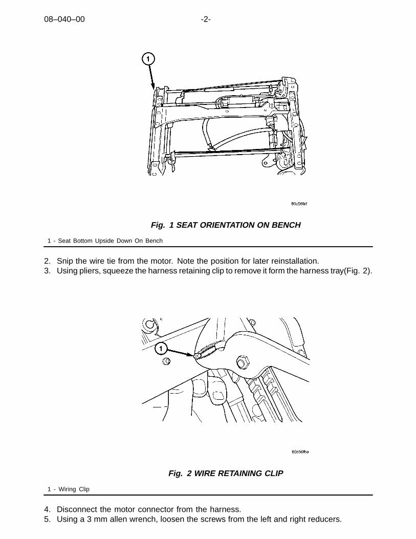
08–040–00 -2-
Fig. 1 SEAT ORIENTATION ON BENCH
1 - Seat Bottom Upside Down On Bench
2. Snip the wire tie from the motor. Note the position for later reinstallation.3. Using pliers, squeeze the harness retaining clip to remove it form the harness tray(Fig. 2).
Fig. 2 WIRE RETAINING CLIP
1 - Wiring Clip
4. Disconnect the motor connector from the harness.5. Using a 3 mm allen wrench, loosen the screws from the left and right reducers.

-3- 08–040–00
Fig. 3 RIGHT AND LEFT REDUCER
1 - Reducer
6. Using the T-20 torx and extension, remove the 4 motor bracket screws.
Fig. 4 MOTOR ATTACHING SCREWS
1 -Attaching Screws
7. Remove the motor assembly and place it on the bench as shown(Fig. 5).

08–040–00 -4-
Fig. 5 MOTOR ORIENTATION ON BENCH
1 - Motor With Flexi-Shafts And Reducers Attached
8. Remove the flexi—shafts from the motor and discard the old motor(Fig. 6).
Fig. 6 FLEX SHAFT AT MOTOR
1 - Flexi-Shaft
9. Using the new motor from kit p/n MR311167, reattach the flexi—shafts.10. Reattach the left and right reducers to the seat as shown(Fig. 7).

-5- 08–040–00
Fig. 7 INSTALLATION OF REDUCERS TO SEAT
1 - Right And Left Reducer
11. Install 4 new motor attaching screws.12. Attach the jumper from kit p/n MR311167 to the motor and harness.13. Insert the retainer clip back into the motor tray and secure the harness to the
motor with the tie strap. Cut the excess tie strap off.14. Reinstall the seat into the vehicle.15. Check seat for proper operation.
POLICY:Reimbursible within the provisions of the warranty.
TIME ALLOWANCE:
Labor Operation No: 08-52-35-91 0.4
FAILURE CODE: Could be one or more
P8 New Part


NUMBER: 08-041-00
GROUP: Electrical
DATE: Jan. 31, 2001
This bulletin is supplied as technical information only and is not an authorization for repair. No part of this publication may be reproduced, stored in a retreival system,or transmitted, in any form or by any means, electronic, mechanical, photocopying, or otherwise, without written permission of DaimlerChrysler Corporation.
SUBJECT:Intermittent Locking/Unlocking Of Doors Without Activating The Power Door Lock Switch
OVERVIEW:This bulletin involves installing new door/liftgate lock cylinder switches.
MODELS:
2000 - 2001 (AB) Ram Van/Wagon
2000 - 2001 (AN) Dakota
2000 - 2001 (BR/BE) Ram Truck
2000 - 2001 (DN) Durango
NOTE: THIS BULLETIN APPLIES TO VEHICLES EQUIPPED WITH VEHICLETHEFT SECURITY SYSTEM (SALES CODE LSA).
SYMPTOM/CONDITION:The door locks will intermittently lock and/or unlock without any activation of the powerdoor lock switch or a clicking sound may be heard coming from the power door locks(repeated locking or repeated unlocking). The condition may occur more frequently in dampconditions such as driving the vehicle in the rain or taking the vehicle through a car wash.
DIAGNOSIS:Vehicles that demonstrate this condition may have water weeping into the door/liftgate lockcylinder switches causing the switch to intermittently short across the internal circuit. This inturn may signal the Central Timer Module (CTM) to activate the power door locks. Becauseof the nature of this problem, it is extremely difficult to diagnose this condition. Therefore,customers that indicate their doors intermittently lock and unlock without having the doorlock switch activated or customers that indicate they hear a repeated clicking noise comingfrom the door locks should have the Repair Procedure performed on their vehicle.

08-041-00 -2-
PARTS REQUIRED:
Qty. Part No. Description
AR (1) 56049282AA Switch, Door Lock Cylinder, Passenger Side,Ram Van/Wagon
AR (1) 56049283AA Switch, Door Lock Cylinder, Driver Side, Ram Van/Wagon
AR (1) 56049276AA Switch, Door Lock Cylinder, Passenger Side,Dakota (Standard And Club Cab)
AR (1) 56049277AA Switch, Door Lock Cylinder, Driver Side, Dakota(Standard And Club Cab)
AR (1) 56049288AA Switch, Door Lock Cylinder, Passenger Side,Dakota (Quad Cab)
AR (1) 56049289AA Switch, Door Lock Cylinder, Driver Side,Dakota (Quad Cab)
AR (1) 56049285AA Switch, Door Lock Cylinder, Driver Side, Ram Truck
AR (1) 56049284AA Switch, Door Lock Cylinder, Passenger Side, Ram Truck
AR (1) 56049278AA Switch, Door Lock Cylinder, Passenger Side, Durango
AR (1) 56049279AA Switch, Door Lock Cylinder, Driver Side, Durango
AR (1) 56049280AA Switch, Liftgate Lock Cylinder, Durango
REPAIR PROCEDURE:
THIS REPAIR IS COMPATIBLE WITH DAIMLERCHRYSLER’S MOBILESERVICE PROGRAM AND DOES NOT REQUIRE HOISTS OR OTHERFULL SERVICE FACILITY SPECIAL EQUIPMENT.
1. Remove the driver, passenger, and liftgate (Durango only) door lock cylinder switches.Refer to the appropriate Service Manual Group 8Q, pages 8Q-4 and 8Q-5 or the serviceinformation available in the MDS2 for DOOR LOCK CYLINDER SWITCH and/orLIFTGATE LOCK CYLINDER SWITCH - REMOVAL AND INSTALLATION procedures.
2. The door lock cylinder switch actuator must be positioned in its neutral positionprior to installing the new switch on the lock cylinder. Rotate the actuator untilthe actuator is positioned as shown in the following figure (Fig. 1).

-3- 08-041-00
Fig. 1 DOOR LOCK SWITCH
1 - DOOR LOCK CYLINDER SWITCH ACTUATOR DRIVER RETAINER
2 - DOOR LOCK CYLINDER SWITCH ACTUATOR INDEX
3 - DOOR LOCK CYLINDER SWITCH
4 - DOOR LOCK CYLINDER SWITCH ACTUATOR
3. Install the driver, passenger, and liftgate (Durango only) door lock cylinder switches.Refer to the appropriate Service Manual Group 8Q, pages 8Q-4 and 8Q-5 or the serviceinformation available in the MDS2 for DOOR LOCK CYLINDER SWITCH and/orLIFTGATE LOCK CYLINDER SWITCH - REMOVAL AND INSTALLATION procedures.
POLICY:Reimbursable within the provisions of the warranty.
TIME ALLOWANCE:
Labor Operation No:
Remove And Replace Door Lock Switch Assembly
Ram Van/Wagon 0.5 Hrs.
Dakota And Ram Truck 0.8 Hrs.
08-80-27-92
Durango 0.9 Hrs.
FAILURE CODE:
P8 New Part


NUMBER: 08-042-00
GROUP: Electrical
DATE: Dec. 29, 2000
This bulletin is supplied as technical information only and is not an authorization for repair. No part of this publication may be reproduced, stored in a retreival system,or transmitted, in any form or by any means, electronic, mechanical, photocopying, or otherwise, without written permission of DaimlerChrysler Corporation.
SUBJECT:Remote Keyless Entry (RKE) Transmitter Programming
OVERVIEW:This bulletin identifies the Remote Keyless Entry (RKE) transmitter partnumbers and programming procedures.
MODELS:
2001 (AN) Dakota
2001 (DN) Durango
2001 (JR) Sebring Sedan/Stratus Sedan/Sebring Convertible
2001 (LH) Concorde/Intrepid/LHS/300M
2001 (RS) Town & Country/Caravan/Voyager
DISCUSSION:Many of the 2001 model year RKE systems have changed internally (data format). Thephysical look and function is very similar to prior models however, the changes in the dataformat has created a major change in the transmitter programming procedure.
PROPER RKE TRANSMITTER PROGRAMMING REQUIRES:1. The DRB III® operating with 50.6 software or higher.2. Only the transmitter part number specified for the model year should be used.
RKE TRANSMITTER PARTS APPLICATION:
Model Part No.
AN/DN 04686481AC
JR 04602260AA
LH 04602260AA
RS 04686481AC, 3 button
RS 04686797AB, 6 button
EQUIPMENT REQUIRED:
CH6000 Scan Tool (DRB III®)CH7000/7001 J1962 Cable
08-042-00 -2-
REPAIR PROCEDURE:
THIS REPAIR IS COMPATIBLE WITH DAIMLERCHRYSLER’S MOBILESERVICE PROGRAM AND DOES NOT REQUIRE HOISTS OR OTHERFULL SERVICE FACILITY SPECIAL EQUIPMENT.
NOTE: ALL TRANSMITTERS (NEW & EXISTING) MUST BE PROGRAMMED ATTHE SAME TIME. IF ONLY ONE TRANSMITTER IS PROGRAMMED, ALL OTHERTRANSMITTERS WILL BE ERASED FROM THE BODY CONTROL MODULE/CENTRALTIMER MODULE/REMOTE KEYLESS ENTRY RECEIVER MODULE MEMORY.
1. With the DRB III® in the programming mode, on any transmitter press the lock andunlock buttons simultaneously – then release to send initial data. Then press andrelease either the lock or unlock button to complete programing the transmitter.
2. Perform procedure on any remaining transmitters. The chime will soundas each transmitter is programmed.
POLICY:Information Only

2000 INDEX
GROUP 09ENGINE
BULLETIN SUBJECT MODELS TSB NO.
GROUP 9 - ENGINE
Normal Accumulation Of A Foamy Oil EmulsionIn The 4.7L Engine Oil Fill Housing
1999 - 2000 WJ, 2000 - AN,DN 09-01-00 Rev. A
A Heavy Oil Or Fuel-Like Odor Coming FromThe Diesel Engine Compartment
1999 - 2000 BR/BE 09-02-00
Engine Oil Seepage Past The Oil Fill Cap On5.9L-24V Diesel Engine
2000 BR/BE
Replacement Engine Break-In Procedure 1992 - 2000 SR 09-04-00
Spark Knock And engine Oil Consumption DueTo Intake Manifold Pan Gasket Oil Leak
1994 - 1999 AB, AN,BR/BE,1994 - 1998 ZJ 1996 - 1998 ZG
09-05-00
Changes To Timing Belt Tensioner Components 1999 - 2000 GS,JA,JX,PL 09-06-00
Air Filter Service 1994 - 2001 BR/BE 09-07-00
Front Cam Seal Retention 1997 - 1998 - GS1995 - 1998 - JA1994 - 1998 - PL
09-08-00


Form TSB-003 Rev. 1.08 February 3, 2000
NUMBER: 09-01-00 Rev A
GROUP: Engine
EFFECTIVE DATE: Sept. 11, 2000
THIS BULLETIN SUPERSEDES TECHNICAL SERVICE BULLETIN 09-01-00, DATEDFEB. 18, 2000, WHICH SHOULD BE REMOVED FROM YOUR FILES. THIS IS ACOMPLETE REVISION AND NO ASTERISKS HAVE BEEN USED TO HIGHLIGHTREVISIONS.
SUBJECT:Foamy Oil Emulsion Accumulation Inside The 4.7L Engine Oil Fill Housing
OVERVIEW:This bulletin involves the installation of a baffle and a revised oil fill housing cap.
MODELS:2000 (AN) Dakota2000 (DN) Durango1999 – 2000 (WJ) Grand Cherokee
NOTE: THIS BULLETIN APPLIES TO VEHICLES EQUIPPED WITH A 4.7L ENGINE.
SYMPTOM/CONDITION:A customer may complain of an oil emulsion accumulation inside the engine oil fill housing.The oil emulsion will normally be foamy and be gray or light brown in color.
The emulsion accumulation will often occur on cooler engine surfaces, like the inside of theoil fill housing. Modern engine oils are designed to address the oil emulsion phenomenon.Oil emulsion accumulation is normal and will not damage the engine
A new baffle and a revised oil fill housing cap have been released. The baffle and oil capwill help to reduce the amount of oil emulsion accumulation within the oil fill housing.
DIAGNOSIS:If the customer has experienced this issue, then perform the Repair Procedure.
PARTS REQUIRED:1 53032126AA Baffle, Oil Fill Housing1 53032389AC Cap, Oil Fill Housing
REPAIR PROCEDURE:
1. Remove old oil fill housing cap.2. Remove any foamy oil emulsion from the inside of the oil fill housing with a clean
cloth.
This bulletin is supplied as technical information only and is not an authorization for repair. No part of this publication may be reproduced, stored in a retrieval system, ortransmitted, in any form or by any means, electronic, mechanical, photocopying, recording, or otherwise, without written permission of DaimlerChrysler Corporation.
THIS REPAIR IS COMPATIBLE WITH DAIMLERCHRYSLER'S MOBILE SERVICE PROGRAM ANDDOES NOT REQUIRE HOISTS OR OTHER FULL SERVICE FACILITY SPECIAL EQUIPMENT.
09-01-00 Rev A -2-
3. Align the flat side of the oil fill housing baffle p/n 53032126AA with the flat surfaceinside the oil fill housing. Insert the oil fill housing baffle into the housing. Make surethe baffle is fully seated in its housing.
4. Install the new oil fill housing cap p/n 53032389AC.
POLICY: Reimbursable within the provisions of the warranty.
TIME ALLOWANCE:Labor Operation No: 09-35-17-91 ................................................................0.2 Hrs.
FAILURE CODE: P8 – New Part

Form TSB-004 Rev. 1.06
NUMBER: 09-02-00
GROUP: Engine
DATE: Feb. 18, 2000
SUBJECT:A Heavy Oil Or Fuel-Like Odor Coming From the Diesel Engine Compartment
MODELS:1999 - 2000 (BR/BE) Ram Truck
NOTE: THIS BULLETIN APPLIES TO VEHICLES EQUIPPED WITH A 5.9L DIESELENGINE.
DISCUSSION:A customer may complain of a heavy oil or fuel-like odor coming from the enginecompartment. This condition may occur after the engine oil has been changed. The odorappears to reduce in intensity as the engine oil ages. This aging usually occurs betweenthe first 300 to 500 miles following the oil change.
NOTE: DO NOT CONFUSE THE HEAVY OIL OR FUEL-LIKE ODOR WITH A DIESELENGINE EXHAUST ODOR.
The odor condition is the result of certain diesel engine oil additives. These oil additivesare blended with the base oil during the manufacture of the engine oil. Some dieselengine oils with the American Petroleum Institute quality rating of CH-4 or CH-4+ may bemore prone to exhibiting the odor condition.
NOTE: THE DAIMLERCHRYSLER RECOMMENDED DIESEL ENGINE OIL, P/N04798231 (QT.) OR P/N 0479832 (GAL.), IS FORMULATED TO MINIMIZE THEHEAVY OIL ODOR CONDITION.
To possibly reduce the further incidence of the odor condition, the integrity of the cowl sealshould be verified. The cowl seal is located between the rear edge of the hood and thecowl panel. Diesel engine oil vapors, which develop during normal engine operation, exitthe engine through the engine road draft tube. The heavy oil or fuel-like odor may leakpast an opening in the cowl seal and enter the passenger compartment through the HVACsystem. This may occur more frequently if the vehicle is at a stop, with the engine running,and the HVAC system is being operated in any mode other than “Re-circulate”.
NOTE: ANY OPENING OR VOIDS IN THE COWL SEAL SHOULD BE CORRECTED.VERIFY THAT FULL CONTACT BETWEEN THE HOOD AND COWL SEAL ISPRESENT ALONG THE ENTIRE LENGTH OF THE SEALING SURFACES.PAY PARTICULAR ATTENTION TO THE SEALING INTEGRITY AT BOTHENDS OF THE COWL SEAL.
POLICY: Information Only
This bulletin is supplied as technical information only and is not an authorization for repair. No part of this publication may be reproduced, stored in a retrieval system, ortransmitted, in any form or by any means, electronic, mechanical, photocopying, recording, or otherwise, without written permission of DaimlerChrysler Corporation.


Form TSB-003 Rev. 1.08
NUMBER: 09-03-00
GROUP: Engine
DATE: Feb. 18, 2000
SUBJECT:Engine Oil Seepage Past The Oil Fill Cap On 5.9L-24V Diesel Engine
OVERVIEW:This bulletin involves the removal of paint overspray in the area around the oil fill cap andthe replacement of the oil fill cap.
MODELS:2000 (BR/BE) Ram Truck
NOTE: THIS BULLETIN APPLIES TO VEHICLES EQUIPPED WITH A 5.9L – 24VDIESEL ENGINE BUILT BEFORE ENGINE SERIAL NUMBER 56664950 WITHA DATE OF MANUFACTURE OF DECEMBER 8, 1999. THIS INFORMATIONIS AVAILABLE ON THE ENGINE DATA PLATE, WHICH IS LOCATED ONTHE LEFT SIDE OF THE ENGINE, AFFIXED TO THE GEAR HOUSING.
SYMPTOM/CONDITION:Oil seepage may be noticed in the area of the oil fill cap. This may be due to paintoverspray around the oil fill opening of the cylinder head valve cover. The paint overspraymay cause an uneven sealing surface.
Another possible cause for the oil seepage may be a damaged oil fill cap o-ring. The o-ring may be cut due to the presence of a sharp corner around the top edge of the cylinderhead cover oil fill opening.
DIAGNOSIS:Inspect the lip of the cylinder head cover oil fill opening. If the oil fill cap o-ring contactsurface on the cylinder head cover has a sharp corner or if paint overspray is present, thenperform the Repair Procedure.
PARTS REQUIRED:1 05014704AA Cap, Engine Oil Fill1(AR) 05016356AB Gasket, Cylinder Head Cover
REPAIR PROCEDURE:
1. Disconnect both battery negative cables2. Loosen the five (5) cylinder head cover bolts. Remove the front three (3) bolts and
leave the rear two bolts in the cover.
This bulletin is supplied as technical information only and is not an authorization for repair. No part of this publication may be reproduced, stored in a retrieval system, ortransmitted, in any form or by any means, electronic, mechanical, photocopying, recording, or otherwise, without written permission of DaimlerChrysler Corporation.
THIS REPAIR IS COMPATIBLE WITH DAIMLERCHRYSLER'S MOBILE SERVICE PROGRAM ANDDOES NOT REQUIRE HOISTS OR OTHER FULL SERVICE FACILITY SPECIAL EQUIPMENT.
09-03-00 -2-
NOTE: THE CYLINDER HEAD VALVE COVER MUST BE REMOVED TO PREVENTPOSSIBLE INTERNAL ENGINE DAMAGE AND/OR OIL CONTAMINATION.
3. Lift the cylinder head cover off of the cylinder head. Remove the cylinder head covergasket from the cover.
4. Remove the oil fill cap from the cylinder head cover.5. Using a fine grit sandpaper, sand the top edge of the cylinder head cover oil fill
opening. Using your finger, verify that the entire top edge circumference of the oil fillopening is smooth and rounded.
6. Clean the cylinder head cover of all debris and oil residue. Clean any oil residue fromthe cylinder head-to-gasket mating surfaces and from the cylinder head gasket.
7. The cylinder head cover gasket is reusable. Inspect the cylinder head cover gasketfor cuts, tears, or cracks. Per your inspection, replace the cover gasket only ifrequired (p/n 05016356AB).
8. Install the cylinder head cover gasket onto the cylinder head with the words “top front”facing up and towards the front of the engine.
9. Install the cylinder head cover to the engine. Torque bolts to 24 Nm (18 ft. lbs.).10. Replace the engine oil fill cap (p/n 05014704AA).11. Connect both battery negative cables to their respective battery.12. Verify proper engine oil level.
POLICY: Reimbursable within the provisions of the warranty.
TIME ALLOWANCE:Labor Operation No: 09-35-25-93 ................................................................0.4 Hrs.
FAILURE CODE: 65 - Leaks

Form TSB-004 Rev. 1.05
NUMBER: 09-04-00
GROUP: Engine
DATE: Feb. 25, 2000
SUBJECT:Replacement Engine Break-In Procedure
MODELS:1992 - 2000 (SR) Viper Roadster/Coupe
DISCUSSION:The following break-in procedure is suggested for any NEW Viper engine. Share thisinformation with your customers as needed.
During the first 1000 miles (1610 km):1. Avoid long periods of engine idling.2. Wait until the engine has reached operating temperature before driving
enthusiastically.3. Check the engine oil level at each fuel fill since a new engine may consume some
oil during the first few thousand miles (this is normal and not a sign of an engineproblem).
4. Keep vehicle speed below 70 mph (113 km/h).5. Do not make any full throttle starts or full throttle accelerations.6. Avoid driving at a constant engine rpm for long periods as follows:
! First 200 mile interval (322 km), light throttle run-ups shifting at a maximumof 2500 rpm. In addition, It is suggested to change the engine oil within thefirst 200 miles of engine break-in.
! Second 200 mile interval (322 km), light throttle run-ups shifting at amaximum of 3500 rpm.
! Third 200 mile interval (322 km), light throttle run-ups shifting at a maximumof 4000 rpm.
! Fourth 200 mile interval (322 km), light throttle run-ups shifting at a maximumof 4500 rpm.
! Fifth 200 mile interval (322 km), light throttle run-ups shifting at a maximumof 5000 rpm.
POLICY: Information Only
This bulletin is supplied as technical information only and is not an authorization for repair. No part of this publication may be reproduced, stored in a retrieval system, ortransmitted, in any form or by any means, electronic, mechanical, photocopying, recording, or otherwise, without written permission of DaimlerChrysler Corporation.

Form TSB-003 Rev. 1.08 February 3, 2000
NUMBER: 09-05-00
GROUP: Engine
DATE: Feb. 25, 2000
THIS BULLETIN SUPERSEDES TECHNICAL SERVICE BULLETIN 09-06-99, DATEDSEP. 10, 1999, WHICH SHOULD BE REMOVED FROM YOUR FILES. THIS IS ACOMPLETE REVISION AND NO ASTERISKS HAVE BEEN USED TO HIGHLIGHTREVISIONS.
SUBJECT:Spark Knock And Engine Oil Consumption Due To Intake Manifold Pan Gasket Oil Leak
OVERVIEW:This bulletin involves the replacement of the engine intake manifold plenum pan gasket.
MODELS:1994 – 1999 (AB) Ram Van1994 – 1999 (AN) Dakota1994 – 1999 (BR/BE) Ram Truck1998 – 1999 (DN) Durango1994 – 1998 (ZJ) Grand Cherokee1996 – 1998 (ZG) Grand Cherokee
NOTE: THIS BULLETIN APPLIES TO VEHICLE EQUIPPED WITH A 3.9L, 5.2L. OR5.9L GASOLINE ENGINE.
SYMPTOM/CONDITION:An engine intake manifold plenum pan gasket oil leak may occur on some V-6 and V-8style engines. The oil leak is internal to the engine so no external oil leakage will bepresent. Two symptoms of this oil leak condition may be present. The vehicle operatormay experience an engine spark knock during acceleration and/or an increase in theamount of engine oil consumed by the engine.
DIAGNOSIS:Make sure Technical Service Bulletin (TSB) 18-48-98 has been performed.
NOTE: IT IS IMPORTANT THAT THE COIL AND SPARK PLUG WIRES ARE ROUTEDEXACTLY AS SPECIFIED IN TSB 18-48-98 TO ACHIEVE THE MOSTBENEFIT.
Inspect the Positive Crankcase Ventilation (PCV) valve. Shake the PCV valve to verifythat the pintle inside of the PCV valve is free. Replace the PVC if the pintle is not free.
If the intake manifold plenum pan gasket is leaking, an additional vacuum source will becreated inside of the engine at the location of the pan gasket leakage. Engine combustionblow-by gases, oil vapor, and air from the crankcase filter/breather may be drawn past theleaking pan gasket and into the intake manifold. In most cases when this condition occurs,an engine at idle will create the highest vacuum and lowest amount of engine blow-by.
This bulletin is supplied as technical information only and is not an authorization for repair. No part of this publication may be reproduced, stored in a retrieval system, ortransmitted, in any form or by any means, electronic, mechanical, photocopying, recording, or otherwise, without written permission of DaimlerChrysler Corporation.

09-05-00 -2-
1. Allow the engine to reach normal operating temperature.2. Stop the engine.3. Disconnect the breather hose from the air cleaner.4. Attach a vacuum / pressure gauge to the end of the breather hose (Figure 1).
1 – VACUUM / PRESSURE GAUGE2 – BREATHER HOSE3 – VALVE COVER BREATHER HOSE PORT________________________________________
FIGURE 1
5. Disconnect the PCV valve hose from the intake manifold.6. Seal off the intake manifold PCV valve hose port opening.7. Seal off the open end of the PCV valve hose (Figure 2).
NOTE: DURING THIS DIAGNOSIS, IT WOULD BE NORMAL FOR THE ENGINE TODEVELOP PRESSURE WITHIN THE ENGINE CRANKCASE. THIS IS DUE TOTHE NORMAL PROCESS OF EXHAUST BLOW-BY GASES LEAKING PASTTHE ENGINE PISTON RINGS AND ACCUMULATING IN THE ENGINECRANKCASE. DO NOT ALLOW MORE THAN 3 PSI (20.7 kPa) OFPRESSURE TO BUILD WITHIN THE ENGINE WHEN PERFORMING THEFOLLOWING DIAGNOSTIC PROCEDURE.
8. Start the warmed engine and observe the vacuum gauge.9. Allow the engine to idle for approximately 30 seconds. Do not allow more than 3 psi
(20.7 kPa) of pressure to develop in the engine crankcase.10. If the attached vacuum / pressure gauge does not indicate that a vacuum is present in
the engine crankcase, then the intake manifold plenum pan gasket is good and nofurther internal engine vacuum leak diagnosis is required.
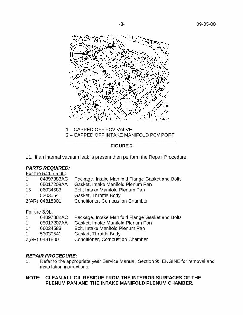
-3- 09-05-00
1 – CAPPED OFF PCV VALVE2 – CAPPED OFF INTAKE MANIFOLD PCV PORT_________________________________________
FIGURE 2
11. If an internal vacuum leak is present then perform the Repair Procedure.
PARTS REQUIRED:For the 5.2L / 5.9L:1 04897383AC Package, Intake Manifold Flange Gasket and Bolts1 05017208AA Gasket, Intake Manifold Plenum Pan15 06034583 Bolt, Intake Manifold Plenum Pan1 53030541 Gasket, Throttle Body2(AR) 04318001 Conditioner, Combustion Chamber
For the 3.9L:1 04897382AC Package, Intake Manifold Flange Gasket and Bolts1 05017207AA Gasket, Intake Manifold Plenum Pan14 06034583 Bolt, Intake Manifold Plenum Pan1 53030541 Gasket, Throttle Body2(AR) 04318001 Conditioner, Combustion Chamber
REPAIR PROCEDURE:1. Refer to the appropriate year Service Manual, Section 9: ENGINE for removal and
installation instructions.
NOTE: CLEAN ALL OIL RESIDUE FROM THE INTERIOR SURFACES OF THEPLENUM PAN AND THE INTAKE MANIFOLD PLENUM CHAMBER.

09-05-00 -4-
NOTE: THE PROPER BOLT TORQUE AND TIGHTENING SEQUENCE IS CRITICALAND MUST BE FOLLOWED WHEN TIGHTENING BOTH THE PLENUM PANBOLTS AND THE INTAKE MANIFOLD FLANGE BOLTS.
3.9L Bolt Tightening Sequence and Torque Procedure:
3.9L Intake Plenum Pan Bolt 3.9L Intake Manifold Bolt Tightening Sequence Tightening Sequence _______________________ ____________________
FIGURE 3 FIGURE 4
3.9L Plenum Pan Bolt Torque ProcedureSTEP WHICH BOLT TORQUE
1 All Bolts 5.4 Nm (48 in. lbs.)2 All Bolts 9.5 Nm (84 in. lbs.)3 Check All Bolts 9.5 Nm (84 in. lbs.)
3.9L Intake Manifold Flange Bolt Torque ProcedureSTEP WHICH BOLT TORQUE
1 1 and 2 1.4 Nm (12 in. lbs.)2 1 and 2 2.7 Nm (24 in. lbs.)3 1 and 2 4.1 Nm (36 in. lbs.)4 1 and 2 5.4 Nm (48 in. lbs.)5 1 and 2 6.7 Nm (60 in. lbs.)6 1 and 2 8.1 Nm (72 in. lbs.)7 3 through 12 8.1 Nm (72 in. lbs.)8 Check All Bolts 8.1 Nm (72 in. lbs.)9 All Bolts 16.3 Nm (12 ft. lbs.)
10 Check All Bolts 16.3 Nm (12 ft. lbs.)
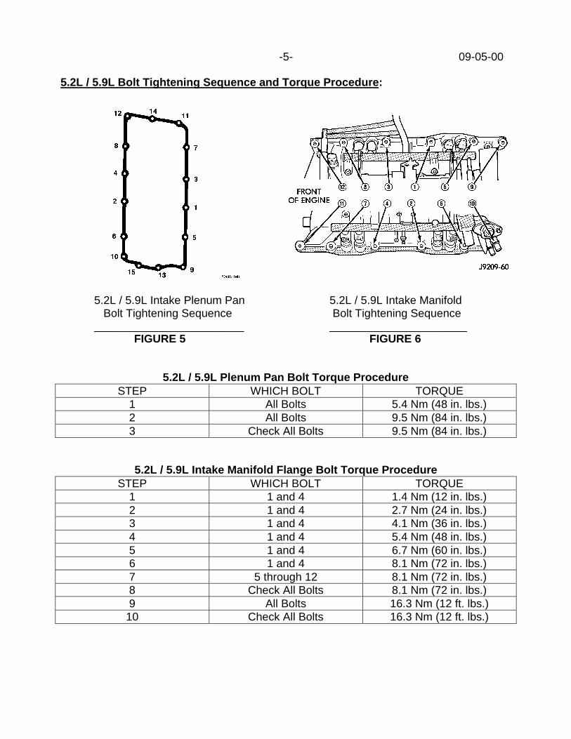
-5- 09-05-00
5.2L / 5.9L Bolt Tightening Sequence and Torque Procedure:
5.2L / 5.9L Intake Plenum Pan 5.2L / 5.9L Intake Manifold Bolt Tightening Sequence Bolt Tightening Sequence________________________ ______________________
FIGURE 5 FIGURE 6
5.2L / 5.9L Plenum Pan Bolt Torque ProcedureSTEP WHICH BOLT TORQUE
1 All Bolts 5.4 Nm (48 in. lbs.)2 All Bolts 9.5 Nm (84 in. lbs.)3 Check All Bolts 9.5 Nm (84 in. lbs.)
5.2L / 5.9L Intake Manifold Flange Bolt Torque ProcedureSTEP WHICH BOLT TORQUE
1 1 and 4 1.4 Nm (12 in. lbs.)2 1 and 4 2.7 Nm (24 in. lbs.)3 1 and 4 4.1 Nm (36 in. lbs.)4 1 and 4 5.4 Nm (48 in. lbs.)5 1 and 4 6.7 Nm (60 in. lbs.)6 1 and 4 8.1 Nm (72 in. lbs.)7 5 through 12 8.1 Nm (72 in. lbs.)8 Check All Bolts 8.1 Nm (72 in. lbs.)9 All Bolts 16.3 Nm (12 ft. lbs.)
10 Check All Bolts 16.3 Nm (12 ft. lbs.)

09-05-00 -6-
2. With the engine reassembled, inspect the coil and spark plug wires for proper routing.Refer to TSB 09-48-98 for additional assistance.
3. Start the engine and allow it to warm to normal engine operating temperature.4. Decarbon the combustion chamber using Mopar Combustion Chamber Conditioner
(p/n 04318001) per the instructions.
NOTE: ALLOW THE COMBUSTION CHAMBER CLEANER TO SOAK INSIDE OFTHE ENGINE FOR 2 TO 2.5 HOURS.
NOTE: A SECOND APPLICATION OF THE COMBUSTION CHAMBERCONDITIONER MAY BE REQUIRED IF THERE WAS A LARGE QUANTITYOF OIL LEAKAGE PAST THE INTAKE PLENUM PAN GASKET.
5. Verify proper engine oil level.
POLICY: Reimbursable within the provisions of the warranty.
TIME ALLOWANCE:Labor Operation No:09-50-15-91 …………………………………………………………………………..….. 3.0 Hrs.
Optional Equipment:09-50-15-60 Air Conditioning Equipped (AN/BR-BE/DN/ZJ) ……..…………………. 0.2 Hrs.09-50-15-60 Air Conditioning Equipped (AB) …………………………………………. 0.8 Hrs.09-50-15-62 Air Injection Pump Equipped (BR/BE) ………………………………….. 0.2 Hrs.09-50-15-65 Power Steering Pump Equipped (if 5.2L and AN/BR-BE/DN/ZJ) ……. 0.2 Hrs.
FAILURE CODE: P8- New Part

Form TSB-003 Rev. 1.07
NUMBER: 09-06-00
GROUP: Engine
DATE: Mar. 10, 2000
SUBJECT:Changes To Timing Belt Tensioner Components
OVERVIEW:This bulletin involves using new procedures when replacing/installing timing belt tensionercomponents.
MODELS:1999 - 2000 (GS) Chrysler Voyager (International Market)1999 - 2000 (JA) Cirrus/Stratus/Breeze1999 - 2000 (JX) Sebring Convertible1999 - 2000 (PL) Neon
NOTE: THIS INFORMATION APPLIES TO VEHICLES EQUIPPED WITH A 2.0L SOHCOR 1.8L ENGINE (INTL. MARKET).
DISCUSSION:Due to parts consolidation, the following components have been released (as a kit) forservice. The following procedures must be reviewed whenever performing service tovehicles that require timing tensioner replacement.
PARTS REQUIRED:1 5018399AA Kit, Timing Tensioner Component (1999 Models) w/o dowel locator1 5018400AA Kit, Timing Tensioner Component (2000 Models) w dowel locatorEach kit consists of a tensioner w/attaching bolts, tensioner pivot assembly, and reartiming belt cover (Figure 1).
3
1
2
4
6
5
1 - REAR TIMING COVER2 - HYDRAULIC TENSIONER3 - SHORT BOLT4 - LONG BOLT5 - BRACKET ASSEMBLY6 - SLEEVED LOCATOR HOLE (IF APPLICABLE)
FIGURE 1
This bulletin is supplied as technical information only and is not an authorization for repair. No part of this publication may be reproduced, stored in a retrieval system, ortransmitted, in any form or by any means, electronic, mechanical, photocopying, recording, or otherwise, without written permission of DaimlerChrysler Corporation.

09-06-00 -2-
NOTE: ALL COMPONENTS MUST BE USED IF THE VEHICLE BEING WORKEDON HAS A MECHANICAL TENSIONER. THE FOLLOWINGPROCEDURES OUTLINE THE REPLACEMENT OF A MECHANICALTENSIONER SYSTEM WITH A HYDRAULIC TENSIONER SYSTEM.
REPAIR PROCEDURE:1. Using the appropriate year service manual, disassemble the front of the engine to the
point where the rear timing belt cover can be replaced.
NOTE: THE 1999 NEON (PL) SERVICE MANUAL P/N 81-270-9125 DESCRIBESBOTH MECHANICAL AND HYDRAULIC TENSIONER SYSTEMS.
NOTE: FOLLOW ALL CAUTIONS AND WARNINGS THAT REFER TO TIMINGBELT AND TENSIONER PROCEDURES.
NOTE: FOLLOW ALL SPECIAL TOOL AND TORQUE REQUIREMENTS THATREFER TO TIMING BELT AND TENSIONER PROCEDURES.
2. Remove and discard the mechanical timing belt tensioner assembly and rear-timingbelt cover (Figure 2). Save the bolts that were used to mount the mechanicaltensioner to the engine.
1
2
1 - REAR TIMING COVER2 - MECHANICAL TENSIONER
FIGURE 2
3. Install a new rear cover and bracket assembly, from kit p/n 5018399AA 1999 Modelsw/o dowel locator or p/n 5018400AA 2000 Models w dowel locator (Figure 1). Torqueall applicable bolts to the specifications listed in the service manual.
NOTE: THE BRACKET ASSEMBLY WITH THE SLEEVED LOCATOR HOLESHOULD ONLY BE USED IF THE DISCARDED MECHANICALTENSIONER HAD A SLEEVED LOCATOR HOLE.
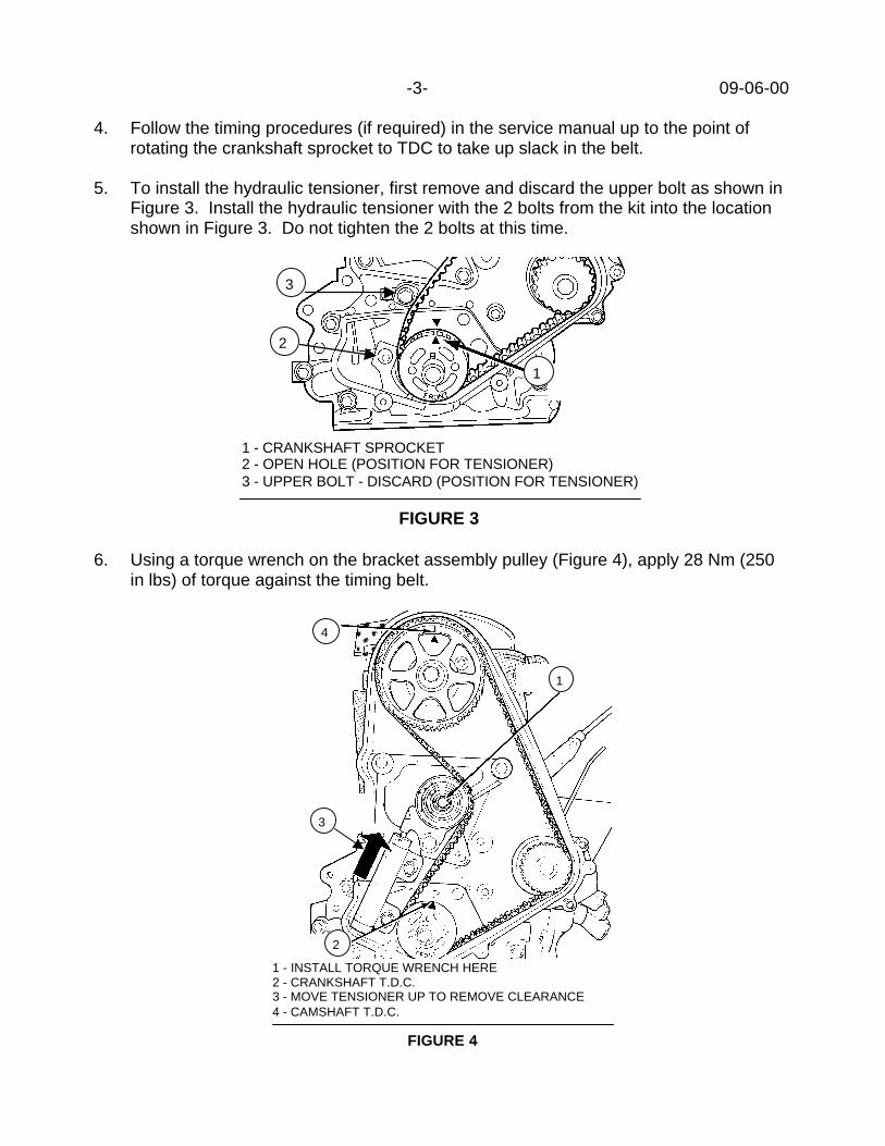
-3- 09-06-00
4. Follow the timing procedures (if required) in the service manual up to the point ofrotating the crankshaft sprocket to TDC to take up slack in the belt.
5. To install the hydraulic tensioner, first remove and discard the upper bolt as shown inFigure 3. Install the hydraulic tensioner with the 2 bolts from the kit into the locationshown in Figure 3. Do not tighten the 2 bolts at this time.
1
2
3
1 - CRANKSHAFT SPROCKET2 - OPEN HOLE (POSITION FOR TENSIONER)3 - UPPER BOLT - DISCARD (POSITION FOR TENSIONER)
FIGURE 3
6. Using a torque wrench on the bracket assembly pulley (Figure 4), apply 28 Nm (250in lbs) of torque against the timing belt.
4
1
2
3
1 - INSTALL TORQUE WRENCH HERE2 - CRANKSHAFT T.D.C.3 - MOVE TENSIONER UP TO REMOVE CLEARANCE4 - CAMSHAFT T.D.C.
FIGURE 4
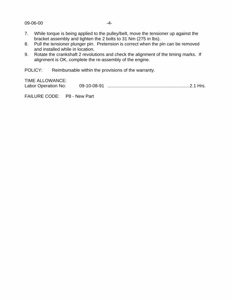
09-06-00 -4-
7. While torque is being applied to the pulley/belt, move the tensioner up against thebracket assembly and tighten the 2 bolts to 31 Nm (275 in lbs).
8. Pull the tensioner plunger pin. Pretension is correct when the pin can be removedand installed while in location.
9. Rotate the crankshaft 2 revolutions and check the alignment of the timing marks. Ifalignment is OK, complete the re-assembly of the engine.
POLICY: Reimbursable within the provisions of the warranty.
TIME ALLOWANCE:Labor Operation No: 09-10-08-91 ................................................................2.1 Hrs.
FAILURE CODE: P8 - New Part

Form TSB-004 Rev. 1.05
NUMBER: 09-07-00
GROUP: Engine
DATE: April 7, 2000
SUBJECT:Air Filter Service
MODELS:1994 - 2001 (BR/BE) Ram Truck
NOTE: THIS BULLETIN APPLIES TO VEHICLES EQUIPPED WITH THE 8.0LENGINE.
DISCUSSION:When servicing the air filter, it is important to ensure that the engine wiring harness isrouted to the left (as viewed from the front of the engine) of the air filter housing attachingclip as shown in Figure 1. Failure to properly route the wiring harness may result in wireharness damage.
POLICY: Information Only
This bulletin is supplied as technical information only and is not an authorization for repair. No part of this publication may be reproduced, stored in a retrieval system, ortransmitted, in any form or by any means, electronic, mechanical, photocopying, recording, or otherwise, without written permission of DaimlerChrysler Corporation.
FIGURE 1
1 - ENGINE WIRING HARNESS2 - AIR CLEANER HOUSING SPRING CLIP3 - AIR CLEANER HOUSING COVER


NUMBER: 09–008–00
GROUP: Engine
DATE: Jan. 12, 2001
This bulletin is supplied as technical information only and is not an authorization for repair. No part of this publication may be reproduced, stored in a retreival system,or transmitted, in any form or by any means, electronic, mechanical, photocopying, or otherwise, without written permission of DaimlerChrysler Corporation.
SUBJECT:Front Cam Seal Retention
OVERVIEW:This bulletin involves installation of a new component to assist cam seal retention.
MODELS:
1997 - 1998 (GS) Chrysler Voyager (International Market)
1995 - 1998 (JA) Cirrus/Stratus/Breeze
1994 - 1998 (PL) Neon
NOTE: THIS INFORMATION APPLIES TO MODELS EQUIPPED WITHA 1.8 OR 2.0L SOHC ENGINE.
DISCUSSION:A new cam seal retainer has been released to retain the front cam seal on1.8L or 2.0L SOHC engines. Whenever a cam seal is replaced, a retainershould be installed to provide positive retention.
PARTS REQUIRED:
Qty. Part No. Description
1 5016733AA Retainer, Front Cam Seal
REPAIR PROCEDURE:1. Upon engine re-assembly after front cam seal installation, install the retainer p/n
5016733AA using the inner cover fasteners as shown in (Fig. 1)

09–008–00 -2-
Fig. 1 OIL SEAL RETAINER
1 - COVER FASTENERS
2 - FRONT SEAL RETAINER
2. Torque the fasteners to 20 Nm (15 ft. lbs.).3. Complete the re-assembly following the applicable service manual.
POLICY:Information Only
2000 INDEX
GROUP 11EXHAUST
BULLETIN SUBJECT MODELS TSB NO.
GROUP 11 - EXHAUST
1700 - 2400 RPM Exhaust Drone 2000 XJ 11-01-00 Rev. A


Form TSB-003 Rev. 1.07
NUMBER: 11-01-00 Rev. A
GROUP: Exhaust
DATE: Aug. 4, 2000
THIS BULLETIN SUPERSEDES TECHNICAL SERVICE BULLETIN 11-01-00, DATEDJULY 21, 2000, WHICH SHOULD BE REMOVED FROM YOUR FILES. THEREVISIONS ARE HIGHLIGHTED WITH ASTERISKS AND INCLUDE A REVISED PARTNUMBER.
SUBJECT:1700 -2400 RPM Exhaust Drone
OVERVIEW:This bulletin involves installing a revised muffler/tailpipe assembly containing an end capreinforcement.
MODELS:2000 (XJ) Cherokee
SYMPTOM/CONDITION:Some vehicles may exhibit a droning sound coming from the exhaust system with theengine operating between 1700 and 2400-RPM. This sound can be heard either in neutralor in gear while driving.
DIAGNOSIS:With the engine at operating temperature and the transmission in park, raise the enginespeed to 1700 RPM and slowly raise it further to 2400 RPM. If the sound is present andthere are no other related conditions such as grounded engine/transmission supports orexhaust system components, perform the Repair Procedure.
PARTS REQUIRED:1 05019872AA Muffler/tailpipe - (Non Flanged Exhaust - MDH 0116XX and prior)1 **52101262AH** Muffler/tailpipe - (Flanged Exhaust - MDH 0117XX and later)
REPAIR PROCEDURE:Using the procedures outlined in the 2000 Cherokee Service Manual, publication number81-370-0046, section 11 page 6, remove the original muffler and tailpipe assembly andinstall the appropriate assembly listed above.
POLICY: Reimbursable within the provisions of the warranty.
This bulletin is supplied as technical information only and is not an authorization for repair. No part of this publication may be reproduced, stored in a retrieval system, ortransmitted, in any form or by any means, electronic, mechanical, photocopying, recording, or otherwise, without written permission of DaimlerChrysler Corporation.
-2- 11-01-00 Rev. A
TIME ALLOWANCE:Labor Operation No:
Muffler - Replace - Flanged Exhaust11-30-01-95 ................................................................0.3 Hrs.
Muffler - Replace - Non-flanged Exhaust11-30-01-96 ................................................................0.5 Hrs.
FAILURE CODE: P8 - New Part

2000 INDEX
GROUP 13FRAME & BUMPERS
BULLETIN SUBJECT MODELS TSB NO.
GROUP 13 - FRAME & BUMPERS
Snapping/Popping/Clunking Noise Heard DuringBraking Or While Driving Over Bumps
2000 AN,DN 13-01-00 Rev. B
Transmission Crossmember Service 2000 - 2001 AN,DN 13-02-00


NUMBER: 13-001-00 Rev. B
GROUP: Frame AndBumpers
DATE: Oct. 27, 2000
This bulletin is supplied as technical information only and is not an authorization for repair. No part of this publication may be reproduced, stored in a retreival system,or transmitted, in any form or by any means, electronic, mechanical, photocopying, or otherwise, without written permission of DaimlerChrysler Corporation.
THIS BULLETIN SUPERSEDES TECHNICAL SERVICE BULLETIN 13–01–00 REV. A,DATED JULY 28, 2000, WHICH SHOULD BE REMOVED FROM YOUR FILES. THIS IS ACOMPLETE REVISION AND NO **ASTERISKS** HAVE BEEN USED TO HIGHLIGHTREVISIONS.
SUBJECT:Snapping/Popping/Clunking Sound Heard During Braking Or While Driving Over Bumps
OVERVIEW:This bulletin involves replacing the torsion bar anchor and on some vehicles, the transmissioncrossmember.
MODELS:
2000 (AN) Dakota
2000 - 2001 (DN) Durango
2000 (R1) Dakota (International Markets)
NOTE: THIS BULLETIN APPLIES TO 4X4 (AN) DAKOTA VEHICLES BUILT BEFORENOVEMBER 15, 1999 (MDH 1115XX), ALL 4X4 (DN) DURANGO VEHICLES, AND ALL(R1) DAKOTA (INTERNATIONAL MARKET) VEHICLES
SYMPTOM/CONDITION:A snapping, popping or clunking sound may be heard while driving and braking over wash-board roads, during a moderately hard stop at low speeds, and/or while slowly driving overmoderate bumps such as a driveway approach.
DIAGNOSIS:1. Road test the vehicle on a smooth surfaced road (preferably concrete) in an area where
you can safely perform several abrupt stops from a speed of 20 mph.2. Accelerate the vehicle to approximately 20 mph.3. Apply the service brakes hard enough to allow the Antilock Brakes to activate. If a snap-
ping, popping or clunking sound is heard, perform the Repair Procedure. If the snapping,popping or clunking sound is not heard, repeat the procedure in reverse. If a snapping,popping or clunking sound is now heard, perform the Repair Procedure. If the snapping,popping or clunking sound is still not heard, repeat the procedure one more time in aforward direction before proceeding to the next step. If a snapping, popping or clunkingsound is now heard, perform the Repair Procedure.
NOTE: DURING ANTILOCK BRAKING, IT IS NORMAL TO HAVE SOME PULSATIONSFELT THROUGH THE BRAKE PEDAL AND THROUGH THE VEHICLE’S SUSPENSION.

13-001-00 Rev. B -2-
DO NOT CONFUSE NORMAL ANTILOCK BRAKING PULSATIONS FOR A SNAP-PING/POPPING/CLUNKING SOUND.
4. Slowly drive the vehicle over a moderate road input such as a driveway approach or acurb. If a snapping, popping or clunking sound is heard, perform the Repair Procedure.
NOTE: AN ALTERNATIVE DIAGNOSIS CAN BE PERFORMED ON A WASHBOARDROAD BY APPLYING A LIGHT TO MODERATE BRAKE WHILE DRIVING.
PARTS REQUIRED:
Qty. Part No. Description
AR (1) 52020253AD Crossmember, Transmission
AR (8) 06506484AA Bolt, Transmission Crossmember
2 52038973 Anchor, Torsion Bar
AR (1) 04318031 Adhesive, Lock & Seal
REPAIR PROCEDURE — (AN) DAKOTA AND (DN) DURANGO BUILT BEFORE NOVEM-BER 15, 1999:1. Raise and support the vehicle with the front suspension allowed to hang.2. If so equipped, remove the front skid plate by removing the three bolts from the front of
the skid plate and the two bolts from the rear of the skid plate. Remove the rear skid plateby removing the two bolts from the rear of the skid plate.
NOTE: THE REAR BOLTS OF THE FRONT SKID PLATE ALSO SECURES THE FRONTOF THE REAR SKID PLATE.
3. Remove the bolts that attach the transmission crossmember to the transmission mount.4. Support the transmission by placing a jack onto the transfer case housing. Using the
transfer case supporting jack, raise the transfer case high enough to be able to get thecrossmember out of the vehicle.
5. Remove the four transmission crossmember to frame attaching bolts.6. Remove the transmission crossmember from the vehicle.7. Turn the torsion bar adjustment bolt counterclockwise to release the spring load (Fig. 1).
NOTE: COUNT AND RECORD THE NUMBER OF TURNS FOR INSTALLATION REFER-ENCE.

-3- 13-001-00 Rev. B
Fig. 1 FRONT SUSPENSION
1 - SWIVEL
2 - LOWER SUSPENSION ARM
3 - TORSION BAR
4 - BEARING
5 - ANCHOR
6 - ADJUSTMENT BOLT
8. Remove the adjustment bolt from the swivel.
CAUTION: THE LEFT AND RIGHT TORSION BARS ARE NOT INTERCHANGEABLE. THEBARS ARE IDENTIFIED AND STAMPED R AND L, FOR RIGHT AND LEFT. THE TORSIONBARS DO NOT HAVE A FRONT OR REAR END AND CAN BE INSTALLED WITH EITHEREND FACING FORWARD.
9. Remove the torsion bar and anchor. Then, remove the anchor from the torsion bar.10. Remove all foreign material from the torsion bar mounting in the lower suspension arm.11. Insert the torsion bar ends into the suspension arm and the new torsion bar anchor p/n
52038973.12. Position the torsion bar anchor and the bearing into the frame crossmember. Install the
adjustment bolt through the bearing, the anchor, and into the swivel.13. Turn the adjustment bolt clockwise the recorded amount of turns.14. Perform Steps 7 through 13 on the other side of the vehicle.15. Install transmission crossmember p/n 52020253AD onto the vehicle. Secure the cross-
member to the frame with eight new bolts p/n 06506484AA. Tighten the bolts to 75 N·m(55 ft. lbs.).
16. Lower the transmission supporting jack so that the transmission mount rests on the trans-mission crossmember.
17. Secure the rear transmission mount to the transmission crossmember with the attachingbolts.
18. If so equipped, install the rear skid plate by attaching the rear of the skid plate with thetwo attaching bolts. Install the front skid plate by attaching the rear of the skid plate withthe two bolts and the front of the skid plate with the three bolts. Tighten all bolts to 23N·m (17 ft. lbs.).

13-001-00 Rev. B -4-
NOTE: THE REAR BOLTS OF THE FRONT SKID PLATE ALSO SECURES THE FRONTOF THE REAR SKID PLATE.
19. Inspect all four tires for the correct size and air pressure.20. Lower the vehicle.21. Move the vehicle to an alignment rack and then jounce the front of the vehicle.22. With the vehicle on a level alignment rack, measure and record the distance between the
alignment rack and the center of the lower suspension arm rear mounting bolt head (Fig.2).
Fig. 2 HEIGHT MEASUREMENT
23. Measure and record the distance between the alignment rack and the center of the frontwheel (Fig. 2).
24. Subtract the first measurement from the second measurement. The difference betweenthe two measurements should be 47 mm (1.85 in.) ± 3.25 mm (0.125 in.) for (AN) Dakotaand 73 mm (2.9 in.) ± 3 mm (0.120 in.) for (DN) Durango.
25. If the vehicle needs to have the suspension height adjusted, turn the torsion bar adjust-ment bolt clockwise to raise the vehicle or counterclockwise to lower the vehicle.
NOTE: ALWAYS RAISE THE VEHICLE TO THE CORRECT SUSPENSION HEIGHT,NEVER LOWER THE VEHICLE TO OBTAIN THE CORRECT SUSPENSION HEIGHT. IFTHE VEHICLE SUSPENSION HEIGHT IS TOO HIGH, LOWER THE VEHICLE BELOWTHE HEIGHT SPECIFICATION. THEN, RAISE THE VEHICLE TO THE CORRECT SUS-PENSION HEIGHT SPECIFICATION. THIS WILL ENSURE THE VEHICLE MAINTAINSTHE PROPER SUSPENSION HEIGHT. IN ADDITION, IF A HEIGHT ADJUSTMENT HASBEEN MADE, MEASURE THE SUSPENSION HEIGHT AGAIN ON BOTH SIDES OF THEVEHICLE.
26. Perform a front wheel alignment check on the vehicle. Refer to the appropriate ServiceManual or the MDS 2, Group 02 for information regarding Wheel Alignment.

-5- 13-001-00 Rev. B
REPAIR PROCEDURE — (DN) DURANGO BUILT AFTER NOVEMBER 15, 1999 AND (R1)DAKOTA:1. Raise and support the vehicle with the front suspension allowed to hang.2. If so equipped, remove the front skid plate by removing the three bolts from the front of
the skid plate and the two bolts from the rear of the skid plate. Remove the rear skid plateby removing the two bolts from the rear of the skid plate.
NOTE: THE REAR BOLTS OF THE FRONT SKID PLATE ALSO SECURES THE FRONTOF THE REAR SKID PLATE.
3. Remove one of the eight transmission crossmember to frame attaching bolts. Apply sev-eral drops of Mopar Lock & Seal Adhesive, p/n 04318031, to the threads of the transmis-sion crossmember bolt. Then, install the crossmember bolt. Tighten the bolts to 75 N·m(55 ft. lbs.). Repeat until all eight bolts have been removed and reinstalled.
4. Turn the torsion bar adjustment bolt counterclockwise to release the spring load (Fig. 1).
NOTE: COUNT AND RECORD THE NUMBER OF TURNS FOR INSTALLATION REFER-ENCE.
5. Remove the adjustment bolt from the swivel.
CAUTION: THE LEFT AND RIGHT TORSION BARS ARE NOT INTERCHANGEABLE. THEBARS ARE IDENTIFIED AND STAMPED R AND L, FOR RIGHT AND LEFT. THE TORSIONBARS DO NOT HAVE A FRONT OR REAR END AND CAN BE INSTALLED WITH EITHEREND FACING FORWARD.
6. Remove the torsion bar and anchor. Then, remove the anchor from the torsion bar.7. Remove all foreign material from the torsion bar mounting in the lower suspension arm.8. Insert the torsion bar ends into the suspension arm and the new torsion bar anchor p/n
52038973.9. Position the torsion bar anchor and the bearing into the frame crossmember. Install the
adjustment bolt through the bearing, the anchor, and into the swivel.10. Turn the adjustment bolt clockwise the recorded amount of turns.11. Perform Steps 4 through 10 on the other side of the vehicle.12. If so equipped, install the rear skid plate by attaching the rear of the skid plate with the
two attaching bolts. Install the front skid plate by attaching the rear of the skid plate withthe two bolts and the front of the skid plate with the three bolts. Tighten all bolts to 23N·m (17 ft. lbs.).
NOTE: THE REAR BOLTS OF THE FRONT SKID PLATE ALSO SECURES THE FRONTOF THE REAR SKID PLATE.
13. Inspect all four tires for the correct size and air pressure.14. Lower the vehicle.15. Move the vehicle to an alignment rack and then jounce the front of the vehicle.16. With the vehicle on a level alignment rack, measure and record the distance between the
alignment rack and the center of the lower suspension arm rear mounting bolt head (Fig.2).

13-001-00 Rev. B -6-
17. Measure and record the distance between the alignment rack and the center of the frontwheel (Fig. 2).
18. Subtract the first measurement from the second measurement. The difference betweenthe two measurements should be 73 mm (2.9 in.) ± 3 mm (0.120 in.) for (DN) Durangoand 40.5 mm (1.60 in.) for (R1) Dakota (International Market).
19. If the vehicle needs to have the suspension height adjusted, turn the torsion bar adjust-ment bolt clockwise to raise the vehicle or counterclockwise to lower the vehicle.
NOTE: ALWAYS RAISE THE VEHICLE TO THE CORRECT SUSPENSION HEIGHT,NEVER LOWER THE VEHICLE TO OBTAIN THE CORRECT SUSPENSION HEIGHT. IFTHE VEHICLE SUSPENSION HEIGHT IS TOO HIGH, LOWER THE VEHICLE BELOWTHE HEIGHT SPECIFICATION. THEN, RAISE THE VEHICLE TO THE CORRECT SUS-PENSION HEIGHT SPECIFICATION. THIS WILL ENSURE THE VEHICLE MAINTAINSTHE PROPER SUSPENSION HEIGHT. IN ADDITION, IF A HEIGHT ADJUSTMENT HASBEEN MADE, MEASURE THE SUSPENSION HEIGHT AGAIN ON BOTH SIDES OF THEVEHICLE.
20. Perform a front wheel alignment check on the vehicle. Refer to the appropriate ServiceManual, Group 02 for information regarding Wheel Alignment.
POLICY:Reimbursable within the provisions of the warranty.
TIME ALLOWANCE:
Labor Operation No:
13-30-02-94 Remove And Install Torsion Bar Anchors AndTransmission Crossmember, Check And AdjustVehicle Suspension Height, And Check AndAdjust Front Wheel Alignment
2.3 Hrs.
13-30-02-95 Remove And Install Torsion Bar Anchors, CheckAnd Adjust Vehicle Suspension Height, AndCheck And Adjust Front Wheel Alignment
1.9 Hrs.
Optional Equipment:
13-30-02-60 Skid Plate Equipped 0.2 Hrs.
FAILURE CODE:
P8 New Part

NUMBER: 13-002-00
GROUP: Frame AndBumpers
DATE: Oct. 27, 2000
This bulletin is supplied as technical information only and is not an authorization for repair. No part of this publication may be reproduced, stored in a retreival system,or transmitted, in any form or by any means, electronic, mechanical, photocopying, or otherwise, without written permission of DaimlerChrysler Corporation.
SUBJECT:Transmission Crossmember Service
MODELS:
2000 - 2001 (AN) Dakota
2000 - 2001 (DN) Durango
DISCUSSION:The fasteners that retain the transmission crossmember to the frame utilize a thread lockpatch on the threads of the fastener. The thread lock patch is required to help prevent thefastener from loosening during normal vehicle usage. When the transmission crossmemberis required to be removed during service, the amount of thread patch material on the fastenerwill deteriorate during fastener removal. To ensure that the fastener retention is not compro-mised after service, the transmission crossmember fastener threads must have Mopar Lock& Seal p/n 04318031 added to the threads of each fastener.
POLICY:Information Only

2000 INDEX
GROUP 14FUEL
BULLETIN SUBJECT MODELS TSB NO.
GROUP 14 - FUEL
Thump/Bump Sound Heard 1-3 Seconds AfterThe Vehicle Comes To A Stop
2000 BR/BE 14-01-00
Crack In Diesel Fuel Filter Housing CoverCaused By An Improper Servicing Procedure
2000 - 2001 BR/BE 14-02-00
Maintenance To The Water-In-Fuel SensorProbes Due To Possible Fuel Contamination
1998 - 2001 BR/BE 14-03-00
Vehicle Is Hard Or Slow To Start 2001 PT 14-04-00
Premium Fuel (91 Octane) Use RequirementWith Durango R/T 5.9L Engine
2000 DN 14-05-00
Longer Than Normal Engine Crank Time Prior ToEngine Start
1999 - 2000 WJ 14-06-00 Rev. A

Form TSB-003 Rev. 1.07
NUMBER: 14-01-00
GROUP: Fuel
DATE: Feb. 4, 2000
SUBJECT:Thump/Bump Sound Heard 1 - 3 Seconds After The Vehicle Comes To A Stop
OVERVIEW:This bulletin involves replacing the fuel tank.
MODELS:2000 (BR/BE) Ram Trucks
NOTE: THIS BULLETIN APPLIES TO 2500 SERIES (BE) CLUB/QUAD CABVEHICLES EQUIPPED WITH THE 6 1/2 FOOT BOX BUILT BEFOREDECEMBER 1, 1999 (MDH 1201XX).
SYMPTOM/CONDITION:Customers may hear a thump/bump sound that occurs 1 - 3 seconds after the vehiclecomes to a complete stop. In some cases, the thump/bump sound may be transmittedthrough the floor of the vehicle allowing the customer to feel the thump/bump in the floorpan of the vehicle. The sound will only occur when the fuel level of the vehicle is between1/2 and 7/8 tank of fuel.
DIAGNOSIS:Since the fuel level of the vehicle must be between 1/2 to 7/8 full, the condition may bedifficult to diagnose. Perform the Repair Procedure on any subject model vehicle in whichthe customer’s concern fits the description identified in the Symptom/Condition sectionlisted above.
PARTS REQUIRED:AR (1) 52102241AD Tank, Fuel, Gasoline EnginesAR (1) 52102238AG Tank, Fuel, Diesel EnginesAR (2) J4000235 Nut, Push
EQUIPMENT REQUIRED:Special Tool 6856
REPAIR PROCEDURE:1. Using the procedures listed in the 2000 Ram Truck Service Manual (Publication No.
81-370-0008), pages 14-21 through 14-24, remove the fuel tank from the vehicle andreplace the fuel tank with the appropriate tank identified in the Parts Required section.
NOTE: SOME COMPONENTS FROM THE REPLACED FUEL TANK MUST BETRANSFERRED TO THE NEW FUEL TANK. REFER TO THE 2000 RAMTRUCK SERVICE MANUAL (PUBLICATION NO. 81-370-0008), GROUP 14FOR INFORMATION REGARDING FUEL TANK COMPONENT REMOVALAND INSTALLATION PROCEDURES.
This bulletin is supplied as technical information only and is not an authorization for repair. No part of this publication may be reproduced, stored in a retrieval system, ortransmitted, in any form or by any means, electronic, mechanical, photocopying, recording, or otherwise, without written permission of DaimlerChrysler Corporation.

14-01-00 -2-
POLICY: Reimbursable within the provisions of the warranty.
TIME ALLOWANCE:Labor Operation No: 14-60-01-95 ................................................................1.3 Hrs.
FAILURE CODE: P8 - New Part
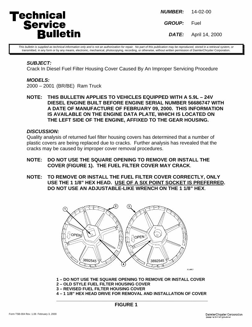
Form TSB-004 Rev. 1.06 February 3, 2000
NUMBER: 14-02-00
GROUP: Fuel
DATE: April 14, 2000
SUBJECT:Crack In Diesel Fuel Filter Housing Cover Caused By An Improper Servicing Procedure
MODELS:2000 – 2001 (BR/BE) Ram Truck
NOTE: THIS BULLETIN APPLIES TO VEHICLES EQUIPPED WITH A 5.9L – 24VDIESEL ENGINE BUILT BEFORE ENGINE SERIAL NUMBER 56686747 WITHA DATE OF MANUFACTURE OF FEBRUARY 09, 2000. THIS INFORMATIONIS AVAILABLE ON THE ENGINE DATA PLATE, WHICH IS LOCATED ONTHE LEFT SIDE OF THE ENGINE, AFFIXED TO THE GEAR HOUSING.
DISCUSSION:Quality analysis of returned fuel filter housing covers has determined that a number ofplastic covers are being replaced due to cracks. Further analysis has revealed that thecracks may be caused by improper cover removal procedures.
NOTE: DO NOT USE THE SQUARE OPENING TO REMOVE OR INSTALL THECOVER (FIGURE 1). THE FUEL FILTER COVER MAY CRACK.
NOTE: TO REMOVE OR INSTALL THE FUEL FILTER COVER CORRECTLY, ONLYUSE THE 1 1/8” HEX HEAD. USE OF A SIX POINT SOCKET IS PREFERRED.DO NOT USE AN ADJUSTABLE-LIKE WRENCH ON THE 1 1/8” HEX.
1 – DO NOT USE THE SQUARE OPENING TO REMOVE OR INSTALL COVER2 – OLD STYLE FUEL FILTER HOUSING COVER3 – REVISED FUEL FILTER HOUSING COVER4 – 1 1/8” HEX HEAD DRIVE FOR REMOVAL AND INSTALLATION OF COVER_______________________________________________________
FIGURE 1
This bulletin is supplied as technical information only and is not an authorization for repair. No part of this publication may be reproduced, stored in a retrieval system, ortransmitted, in any form or by any means, electronic, mechanical, photocopying, recording, or otherwise, without written permission of DaimlerChrysler Corporation.
14-02-00 -2-
The removal of the fuel filter cover normally requires higher effort than its installation. Thismay be due to the o-ring used to seal the fuel filter cover to the fuel filter housing. Thesealing o-ring is designed to swell in the presence of fuel, so that a better seal may beobtained between the cover and housing.
NOTE: THE O-RING USED TO SEAL THE FUEL FILTER COVER TO ITS HOUSINGCAN ONLY BE USED ONE TIME.
A new o-ring is packaged with each replacement fuel filter or with a replacement cover.
The fuel filter cover has been revised to prevent the use of the square opening forservicing purposes.
CAUTION: THE MAXIMUM INSTALLATION TORQUE FOR BOTH STYLE FUELFILTER HOUSING COVERS IS 34 NM (25 FT. LBS.).
POLICY: Information Only
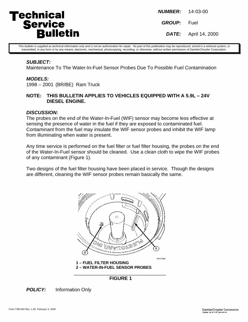
Form TSB-004 Rev. 1.06 February 3, 2000
NUMBER: 14-03-00
GROUP: Fuel
DATE: April 14, 2000
SUBJECT:Maintenance To The Water-In-Fuel Sensor Probes Due To Possible Fuel Contamination
MODELS:1998 – 2001 (BR/BE) Ram Truck
NOTE: THIS BULLETIN APPLIES TO VEHICLES EQUIPPED WITH A 5.9L – 24VDIESEL ENGINE.
DISCUSSION:The probes on the end of the Water-In-Fuel (WIF) sensor may become less effective atsensing the presence of water in the fuel if they are exposed to contaminated fuel.Contaminant from the fuel may insulate the WIF sensor probes and inhibit the WIF lampfrom illuminating when water is present.
Any time service is performed on the fuel filter or fuel filter housing, the probes on the endof the Water-In-Fuel sensor should be cleaned. Use a clean cloth to wipe the WIF probesof any contaminant (Figure 1).
Two designs of the fuel filter housing have been placed in service. Though the designsare different, cleaning the WIF sensor probes remain basically the same.
1 – FUEL FILTER HOUSING2 – WATER-IN-FUEL SENSOR PROBES
__________________________________FIGURE 1
POLICY: Information Only
This bulletin is supplied as technical information only and is not an authorization for repair. No part of this publication may be reproduced, stored in a retrieval system, ortransmitted, in any form or by any means, electronic, mechanical, photocopying, recording, or otherwise, without written permission of DaimlerChrysler Corporation.


Form TSB-003 Rev. 1.07
NUMBER: 14-04-00
GROUP: Fuel
DATE: June 9, 2000
SUBJECT:Vehicle Is Hard Or Slow To Start
OVERVIEW:This bulletin involves the diagnosis and if necessary, replacement of the fuel pumpmodule.
MODELS:2001 (PT) PT Cruiser
NOTE: THIS BULLETIN APPLIES TO VEHICLES BUILT PRIOR TO MAY 23, 2000(MDH 0523XX).
SYMPTOM/CONDITION:The vehicle is hard or slow to start. Crank times over 4 seconds. This may be due tocontamination in the fuel pressure regulator inside the fuel pump. The contamination wasthe result of the supplier process. The new fuel pump module contains a screen internal tothe pressure regulator that prohibits contamination from entering the regulator.
DIAGNOSIS:WARNING: THE FUEL SYSTEM IS UNDER A CONSTANT PRESSURE (EVEN WITH
THE ENGINE OFF). BEFORE TESTING OR SERVICING ANY FUELSYSTEM HOSE, FITTING OR LINE, THE FUEL SYSTEM PRESSUREMUST BE RELEASED.
Check the fuel system pressure by installing a fuel pressure gauge on the fuel rail. Startthe vehicle and record the fuel pressure. Normal fuel pressure is 58 psi +/- 5 psi. Turn thevehicle off and let the vehicle sit for 20 minutes. Without starting the vehicle, check thefuel pressure. If the fuel pressure has dropped below 25 psi, perform the RepairProcedure. If the fuel pressure is in the normal range (58 psi +/- 5 psi), repeat the fuelpressure test. If the fuel pressure on the second test is below 25 psi, perform the RepairProcedure. If the fuel pressure is again normal, refer to the PT Cruiser PowertrainDiagnostic Manual (Publication No. 81-699-99070) for further diagnosis. Do not performthis Technical Service Bulletin on a vehicle with normal fuel pressure as it will not resolvethe hard or slow to start condition.
PARTS REQUIRED:1 05017204AB Fuel Pump Module Kit1 04275086 Label, Authorized Modification
EQUIPMENT REQUIRED:Fuel Pressure Gauge
This bulletin is supplied as technical information only and is not an authorization for repair. No part of this publication may be reproduced, stored in a retrieval system, ortransmitted, in any form or by any means, electronic, mechanical, photocopying, recording, or otherwise, without written permission of DaimlerChrysler Corporation.

14-04-00 -2-
REPAIR PROCEDURE:1. Remove and replace the fuel pump module following the procedure in the PT Cruiser
Service Manual (Publication No. 81-370-1111) beginning on page 14-12.
NOTE: THE FOLLOWING STEP IS REQUIRED BY LAW.
2. Type the necessary information on the “Authorized Modification Label” p/n 04275086and attach the label near the VECI label (Figure 1).
POLICY: Reimbursable within the provisions of the warranty.
TIME ALLOWANCE:Labor Operation No: 14-50-01-93 ...............................................................0.9 Hrs.
FAILURE CODE: P8 - New Part

Form TSB-004 Rev. 1.06 February 3, 2000
NUMBER: 14-05-00
GROUP: Fuel
DATE: June 09, 2000
SUBJECT:Premium Fuel (91 Octane) Use Requirement With Durango R/T 5.9L Engine.
MODELS:2000 (DN) Durango
NOTE: THIS BULLETIN APPLIES TO VEHICLES EQUIPPED WITH THE R/T 5.9LENGINE.
DISCUSSION:The 5.9L engine in the Durango R/T has been calibrated to operate with fuel that is ratedat 91 octane or higher (premium fuel). Use of fuel with a lower octane may impact engineperformance and durability.
NOTE: USE OF FUELS WITH A RATING OF LESS THAN 91 OCTANE WILL CAUSEA SPARK KNOCK CONDITION AND MAY RESULT IN ENGINE DAMAGE.
The use of premium or 91 octane fuel is identified on the vehicle in several ways:1. A yellow and red “Premium Fuel Only” label is permanently affixed on the inside of the
fuel fill door.2. As a reminder to the dealer, a large temporary label with the words “Attention: Upon
Delivery Of This Vehicle To Dealer, Fill Tank With Premium Fuel Only !!!” is affixed tothe driver side rear quarter window.
3. In each vehicle, an owner Tips Card will be attached to the inside rear view mirror. Itinstructs the vehicle operator that 91 octane fuel is required.
4. The Durango R/T Owner Manual instructs the vehicle operator that the 5.9L engine inthe R/T model is calibrated for premium grade gasoline.
NOTE: PREMIUM FUEL SHOULD BE USED AT ALL TIMES BEGINNING WITH THEA COMPLETE FUEL TANK FILL BY THE DEALER UPON VEHICLE RECEIPT.
It is the dealership’s responsibility to verify:1. The Durango R/T 5.9L fuel tank is filled with premium fuel as soon as possible after the
receipt of the vehicle from the vehicle shipper.2. The dealership sales staff is aware of the need for premium fuel use, especially if the
vehicle is not prepped immediately after it is received from the vehicle shipper. Toassure top performance, the Durango R/T 5.9L vehicle should not be demonstrateduntil the fuel tank has been filled completely with a good premium grade fuel.
3. The importance of using premium fuel is reviewed with the new vehicle owner at thetime of vehicle purchase / delivery.
POLICY: Information Only
This bulletin is supplied as technical information only and is not an authorization for repair. No part of this publication may be reproduced, stored in a retrieval system, ortransmitted, in any form or by any means, electronic, mechanical, photocopying, recording, or otherwise, without written permission of DaimlerChrysler Corporation.


Form TSB-003 Rev. 1.08 February 3, 2000
NUMBER: 14-06-00 Rev A
GROUP: Fuel
DATE: Sep. 15, 2000
THIS BULLETIN SUPERSEDES TECHNICAL SERVICE BULLETIN 14-06-00, DATEDAUG. 18, 2000, WHICH SHOULD BE REMOVED FROM YOUR FILES. ALL REVISIONSARE HIGHLIGHTED WITH **ASTERISKS** AND INCLUDE A REVISION TO THELABOR OPERATION NUMBER.
SUBJECT:Longer Than Normal Engine Crank Time Prior To Engine Start
OVERVIEW:This bulletin involves the repair or the replacement of the fuel pump module.
MODELS:1999 – 2000 (WJ) Grand Cherokee
NOTE: THIS BULLETIN APPLIES TO VEHICLES EQUIPPED WITH A GASOLINEENGINE BUILT BEFORE MAY 26, 2000 (MDH 0526XX).
SYMPTOM/CONDITION:The customer may experience a longer than normal engine cranking time prior to enginestart. Overtime, the engine start time may gradually become even longer.
This condition may be due to low initial fuel pressure at time of engine crank. The low fuelpressure may be caused by a worn o-ring (quad ring) in the fuel module assembly or byplastic contaminant entering the fuel pump.
DIAGNOSIS:1. If the fuel system is suspected as the possible cause of the condition, then perform
TSB 14-05-99 (Fuel System Pressure Diagnostic Procedure).2. Verify that the fuel system pressure drops more than 207 kPa (30 psi) in less than five
(5) minutes. If not, then the long crank time may not be due to the fuel system and therest of the engine system must be diagnosed.
3. If diagnosis determines that the cause of the fuel system pressure loss is due to thefuel pump module, then inspect the part label on the fuel pump module to determinethe module build date code. The part label is affixed to the fuel pump module wireharness (pigtail) near the electrical connector to the body wire harness (Figure 2).Inspect the bottom row of numbers on the module label and locate the module builddate code. Determine the date of module build (Julian date). The first two numbers inthe code indicate the calender year (1998, 1999, or 2000) and the remaining threenumbers (1 to 365) represent the day (Figure 1).
4. If the Julian date code on the fuel pump module parts label falls on or between 98152to 99308 (June 01, 1998 to November 04, 1999), then the fuel pump module kit withquad ring p/n 05019308AA should be installed (See Repair Procedure - Section B).
This bulletin is supplied as technical information only and is not an authorization for repair. No part of this publication may be reproduced, stored in a retrieval system, ortransmitted, in any form or by any means, electronic, mechanical, photocopying, recording, or otherwise, without written permission of DaimlerChrysler Corporation.

14-06-00 Rev A -2-
5. If the Julian date code on the fuel pump module parts label falls on or between 99309to 00136 (November 05, 1999 to May 15, 2000), then the fuel pump module assemblyp/n 05012380AB should be installed (See Repair Procedure - Section A).
NOTE: SOME FUEL PUMP MODULES BUILT BETWEEN NOV. 5, 1999 AND MAY 15,2000 (99309 to 00136) HAVE BEEN USED AS A SERVICE REPLACEMENTPART IN A PREVIOUS SERVICE REPAIR. IT IS IMPORTANT THAT THEMODULE BUILD DATE CODE BE DETERMINED PRIOR TO EACH REPAIR.
FIGURE 11 – FUEL PUMP MODULE PART NUMBER LABEL2 – JULIAN BUILD DATE3 – YEAR (99 = 1999)4 – DAY (246 = SEPT 03)_________________________________________
PARTS REQUIRED:For fuel modules built on or between 98152 to 99308 (Julian date):1 05019308AA Kit, Fuel Pump Module Repair
For fuel pump modules built on or between 99309 to 00136 (Julian date):1 05012380AB Module, Fuel Pump
EQUIPMENT REQUIRED:1 6856 Wrench, Fuel Module Locknut Spanner1 5069 Kit, Pressure Test2 6539 Adapter, Fuel Pressure (for 5/16” fuel lines)
REPAIR PROCEDURE:
NOTE: WHENEVER THE FUEL PUMP MODULE IS SERVICED, SPECIAL CAREMUST BE TAKEN TO PREVENT ANY DAMAGE TO THE FUEL LEVELSENDING UNIT, OR TO THE FLOAT OR FLOAT ARM.
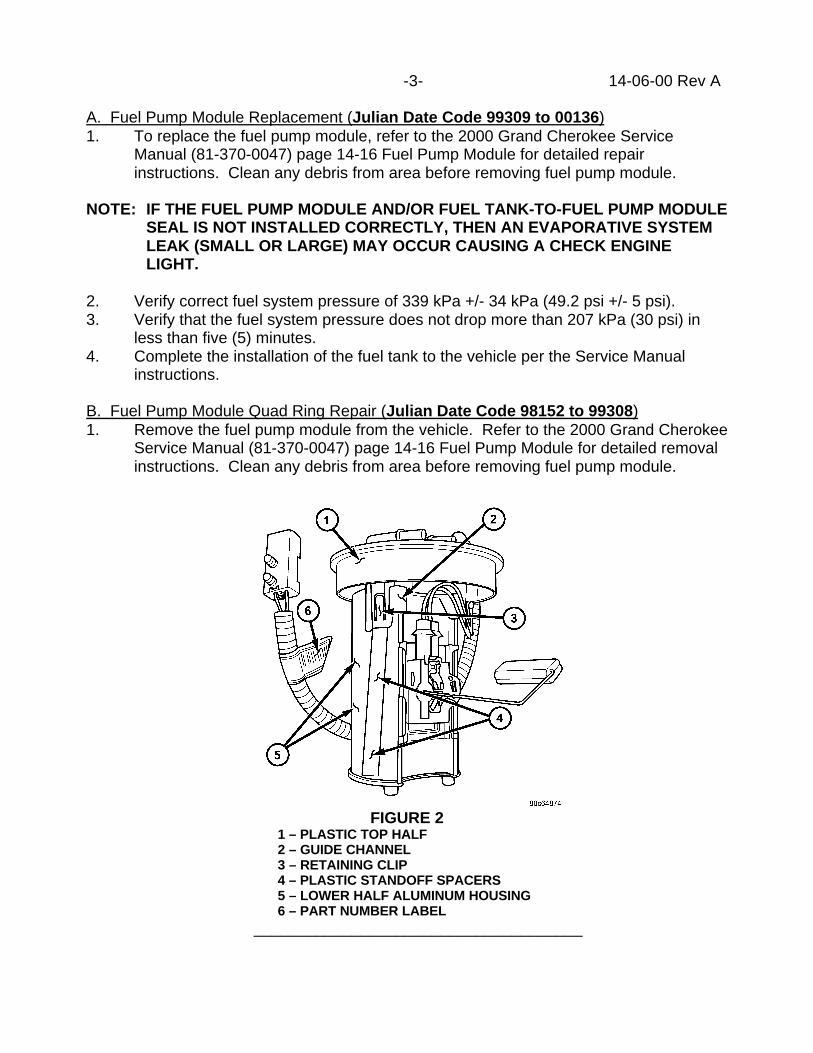
-3- 14-06-00 Rev A
A. Fuel Pump Module Replacement (Julian Date Code 99309 to 00136)1. To replace the fuel pump module, refer to the 2000 Grand Cherokee Service
Manual (81-370-0047) page 14-16 Fuel Pump Module for detailed repairinstructions. Clean any debris from area before removing fuel pump module.
NOTE: IF THE FUEL PUMP MODULE AND/OR FUEL TANK-TO-FUEL PUMP MODULESEAL IS NOT INSTALLED CORRECTLY, THEN AN EVAPORATIVE SYSTEMLEAK (SMALL OR LARGE) MAY OCCUR CAUSING A CHECK ENGINELIGHT.
2. Verify correct fuel system pressure of 339 kPa +/- 34 kPa (49.2 psi +/- 5 psi).3. Verify that the fuel system pressure does not drop more than 207 kPa (30 psi) in
less than five (5) minutes.4. Complete the installation of the fuel tank to the vehicle per the Service Manual
instructions.
B. Fuel Pump Module Quad Ring Repair (Julian Date Code 98152 to 99308)1. Remove the fuel pump module from the vehicle. Refer to the 2000 Grand Cherokee
Service Manual (81-370-0047) page 14-16 Fuel Pump Module for detailed removalinstructions. Clean any debris from area before removing fuel pump module.
FIGURE 21 – PLASTIC TOP HALF2 – GUIDE CHANNEL3 – RETAINING CLIP4 – PLASTIC STANDOFF SPACERS5 – LOWER HALF ALUMINUM HOUSING6 – PART NUMBER LABEL
_____________________________________
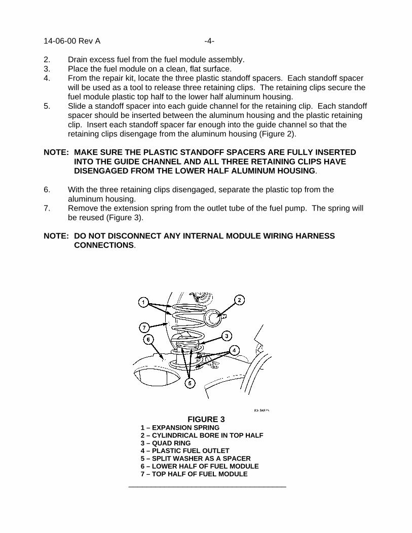
14-06-00 Rev A -4-
2. Drain excess fuel from the fuel module assembly.3. Place the fuel module on a clean, flat surface.4. From the repair kit, locate the three plastic standoff spacers. Each standoff spacer
will be used as a tool to release three retaining clips. The retaining clips secure thefuel module plastic top half to the lower half aluminum housing.
5. Slide a standoff spacer into each guide channel for the retaining clip. Each standoffspacer should be inserted between the aluminum housing and the plastic retainingclip. Insert each standoff spacer far enough into the guide channel so that theretaining clips disengage from the aluminum housing (Figure 2).
NOTE: MAKE SURE THE PLASTIC STANDOFF SPACERS ARE FULLY INSERTEDINTO THE GUIDE CHANNEL AND ALL THREE RETAINING CLIPS HAVEDISENGAGED FROM THE LOWER HALF ALUMINUM HOUSING.
6. With the three retaining clips disengaged, separate the plastic top from thealuminum housing.
7. Remove the extension spring from the outlet tube of the fuel pump. The spring willbe reused (Figure 3).
NOTE: DO NOT DISCONNECT ANY INTERNAL MODULE WIRING HARNESSCONNECTIONS.
FIGURE 31 – EXPANSION SPRING2 – CYLINDRICAL BORE IN TOP HALF3 – QUAD RING4 – PLASTIC FUEL OUTLET5 – SPLIT WASHER AS A SPACER6 – LOWER HALF OF FUEL MODULE7 – TOP HALF OF FUEL MODULE
___________________________________
-5- 14-06-00 Rev A
8. With one hand, and using two fingers, pinch the black quad ring. Squeeze the quadring to one side of the outlet tube so it can be removed using your other hand.Remove and discard the quad ring.
NOTE: DO NOT USE ANY SHARP TOOL TO REMOVE THE QUAD RING FROM ITSRETAINING GROOVE. DAMAGE TO THE GROOVE MAY DAMAGE THESEALING SURFACE.
9. Use shop air to clean the plastic fuel outlet and retaining groove. Clean thecylindrical bore, located in the plastic top half. Inspect all mating surfaces fordamage, scratches, and debris.
10. Locate the plastic split washer in the repair kit. The split washer will be used to takeup the extra space in the quad ring retaining groove on the plastic fuel outlet tube.
11. Slide the split washer around and onto the quad ring retaining groove.
NOTE: THE WHITE SPACER IS INSTALLED CORRECTLY WHEN THE OUTERDIAMETER OF THE SPLIT WASHER IS ALIGNED WITH THE OUTERDIAMETER OF THE PLASTIC OUTLET TUBE.
12. Using the enclosed packet of lubricant, lubricate the new quad ring, its retaininggroove, and the mating cylindrical bore located in the plastic top half. Save somelubricant for later use. No other lubricant should be used.
13. Install the new quad ring over the top of the plastic fuel outlet tube. Make sure thequad ring does not twist during installation. Carefully work the quad ring around theplastic outlet tube and into its retaining groove. Do not over stretch the quad ring.The quad ring should be positioned above the split washer.
NOTE: MAKE CERTAIN THAT THE QUAD RING HAS NOT TWISTED OR BEENSTRETCHED EXCESSIVELY. INSPECT THE ENTIRE QUAD RING AND SPLITWASHER FOR PROPER POSITIONING.
14. Lubricate the quad ring again with lubricant from the packet.15. Install the previously removed extension spring over the plastic fuel outlet tube.16. Carefully align the top half retaining clips to the guide channels in the aluminum
housing. Make certain that the cylindrical bore aligns with the plastic outlet tube.17. Compress the plastic top half onto the aluminum housing until the retaining clips
have fully engaged the slots in the aluminum housing. Inspect each retaining clipand the extension spring.
18. Press the plastic top half of the fuel pump module down onto the aluminum housinguntil the fuel module is in its fully collapsed position. When released, the top half ofthe fuel pump module should freely rebound to its fully extended position.
19. Repeat Step 18 twice.20. Verify that the fuel pump module returns to its fully extended position. If not, the top
half must be removed and additional lubricant must be applied to the quad ring andmating surfaces.
21. Inspect the fuel pump module filter for damage or contamination.22. Install the fuel pump module-to-fuel tank seal to the fuel pump module.

14-06-00 Rev A -6-
23. Install the fuel pump module to the fuel tank. Refer to the 2000 Grand CherokeeService Manual (81-370-0047) page 14-16 Fuel Pump Module for detailedinstallation instructions.
NOTE: IF THE FUEL PUMP MODULE AND/OR FUEL TANK-TO-FUEL PUMP MODULESEAL IS NOT INSTALLED CORRECTLY, THEN AN EVAPORATIVE SYSTEMLEAK (SMALL OR LARGE) MAY OCCUR CAUSING A CHECK ENGINELIGHT.
24. Verify correct fuel system pressure of 339 kPa +/- 34 kPa (49.2 psi +/- 5 psi).25. Verify that the fuel system pressure does not drop more than 207 kPa (30 psi) in
less than five (5) minutes26. Complete the installation of the fuel tank to the vehicle per the Service Manual
instructions.
POLICY: Reimbursable within the provisions of the warranty.
TIME ALLOWANCE:Labor Operation No:
**14-50-01-97** (Replace fuel pump module assembly) ….…….…… 1.2 Hrs.14-50-01-98 (Replace fuel pump module quad ring) …………………. 1.3 Hrs.14-50-01-66 (Optional Equipment – Trailer Tow) ……………….……. 1.0 Hrs.
FAILURE CODE: P8 – New Part

2000 INDEX
GROUP 18DRIVEABILITY
BULLETIN SUBJECT MODELS TSB NO.
GROUP 18 - DRIVEABILITY
Misdiagnosed Leak Detection Pump SystemsWith DTC P1494,P0442,P0455, or P0456
1997 - 2000 AB,AN,BR/BE,DN,FJ,JA,JX,LH,NS,PL,PR,SR,TJ,WJ,XJ,1997 - 1998 ZJ
18-01-00
PCV Valve Freeze Up 1996 - 2000 NS 18-02-00
EGR Monitor Diagnostic Test Difficult to Com-plete Or 9NOT READY9 At High Altitudes (Above4000 Feet)
1999 - 2000 NS 18-03-00
Erroneous MIL With P0441 - EVAP PURGEFLOW MONITOR FAILURE
2001 - PT 18-04-00
1998 Model Year Engine Spark Knock 1998 - AB,AN,BR/BE,DN 18-05-00 Rev. G
1999 Model Year Engine Spark Knock 1999 - AB,AN,BR/BE,DN 18-06-00 Rev. C
Erroneous MIL With P0645, P1282, P1489,P1490, Or P1495 After Shutting Off IgnitionWhile In Gear With Brake Pedal Depressed
2001 PT 18-07-00
Erroneous MIL Illumination Due To DTC P0107 -Map Sensor Voltage Too Low
1996 - 1998 AB,AN,BR/BE,DN,XJ, 1997 - 1998 TJ
18-08-00
2000 Model Year Engine Spark Knock 2000 - AB,AN,BR/BE 18-09-00 Rev. D
No Response From TCM When Using Some Ge-neric Scan Tools
2000 - GS,JA,JX,NS,PR 18-10-00
Low Voltage Clutch Protection - Added DTC -P1714 Low Battery Voltage
1999 - FJ,GS,JA,JX,LH,LHS,300M,NS,PR
18-11-00
Revised MIL Feature For Customer OBDII I/MReadiness
2001 - JR,PL,PT,RG,RS 18-12-00
Idle Fluctuation And/Or Tip In Hesitation At LowSpeed
2000 - LH 18-13-00

BULLETIN SUBJECT MODELS TSB NO.
4 To 3 Harsh Downshift In The 25 TO 40 MPHRange
2000 LH/LHS/300M 18-14-00
Driveability Enhancements With Winter Fuel UseAnd For Hard Not Engine Restarts
1999 - 2001 BR/BE 18-15-00 Rev. A
Poor A/C Or Engine Performance 2001 PL 18-16-00
Torque Converter Clutch Control/Kickdown ShiftQuality Improvements
1999 - LH,LHS/300M 18-17-00
Driveability Improvements/System Enhancements 2001 PT 18-18-00
Driveability Improvements 2000 - PL 18-19-00
Tip In Hesitation Caused By High DI Fuel 2001 - PL 18-20-00
Intermittent VTA, Overhead Temperature DisplaySlow To Update, Poor AC Performance AfterStart UP
1998 - 1999 LH,LHS/300M 18-21-00
2001 M.Y. Engine Spark Knock 2001 - BR/BE,DN 18-22-00
4.7L Engine Performance Enhancements 1999 - 2000 WJ 200 - DN, AN 18-23-00 Rev. A
Low Engine Power When The Automatic Trans-mission Is In Overdrive
2001 - BR/BE 18-24-00

Form TSB-004 Rev. 1.05
NUMBER: 18-01-00
GROUP: Vehicle Performance
DATE: Feb. 4, 2000
SUBJECT:Misdiagnosed Leak Detection Pump Systems With DTC P1494, P0442, P0455, OR P0456
MODELS:1997 - 2000 (AB) Ram Van1997 - 2000 (AN) Dakota1997 - 2000 (BR/BE) Ram truck1998 - 2000 (DN) Durango1997 - 2000 (FJ) Avenger/Sebring/Talon1997 - 2000 (JA) Cirrus/Stratus/Breeze1997 - 2000 (JX) Sebring Convertible1997 - 2000 (LH) Concorde/Intrepid/LHS/300M/Vision1997 - 2000 (NS) Town & Country/Caravan/Voyager1997 - 2000 (PL) Neon1997 - 2000 (PR) Prowler1997 - 2000 (SR) Viper/Viper GTS1997 - 2000 (TJ) Wrangler1999 - 2000 (WJ) Grand Cherokee1997 - 2000 (XJ) Cherokee1997 - 1998 (ZJ) Grand Cherokee
DISCUSSION:During evaporative system diagnosis, Leak Detection Pumps have mistakenly beenreplaced. A thorough inspection for pinched, kinked, or disconnected supply vacuum lines(as currently listed in the Powertrain Diagnostic Procedures) is a critical step in diagnosingDTC P1494 (LDP SW OR MECHANICAL FAULT). Additionally, the other evaporative leakfaults (DTC P0442 - SMALL LEAK, P0455 - LARGE LEAK, and P0456 - VERY SMALLLEAK) should have the supply vacuum lines examined for pinches or kinks prior to anyLDP component replacement.
The supply vacuum lines should be checked from the engine compartment all the way tothe fuel tank, including the LDP and purge system.
NOTE: VERIFY ALL RELATED SUPPLY VACUUM LINE ROUTINGS FORPINCHES, KINKS, OR DISCONNECTION'S BEFORE REPLACING LDPSYSTEM COMPONENTS.
POLICY: Information Only
This bulletin is supplied as technical information only and is not an authorization for repair. No part of this publication may be reproduced, stored in a retrieval system, ortransmitted, in any form or by any means, electronic, mechanical, photocopying, recording, or otherwise, without written permission of DaimlerChrysler Corporation.


Form TSB-004 Rev. 1.05
NUMBER: 18-02-00
GROUP: Vehicle Performance
DATE: Feb. 4, 2000
SUBJECT:PCV Valve Freeze Up
MODELS:1996 - 2000 (NS) Town & Country/Caravan/Voyager
NOTE: THIS INFORMATION APPLIES TO VEHICLES EQUIPPED WITH A 3.0LENGINE BUILT PRIOR TO AUGUST 16, 1999 (MDH0816XX). VEHICLESBUILT AFTER THE ABOVE DATE HAVE THE NEW VALVE.
DISCUSSION:Under extremely cold conditions, the PCV system may freeze causing crankcase pressurebuildup. This could lead to excess oil consumption.
A higher rate PCV valve p/n MD369353 is released that will prevent this condition.Additionally, this new valve must be used as the standard replacement valve for allapplicable models.
PARTS REQUIRED:1 MD369353 PCV ValveAR (1) 04275086 Label, Authorized Modification
Vehicles built prior to the above clean point will require an “Authorized Modification Label”p/n 04275086. Type the necessary information on the label and attach the label near theVECI label (Figure 1).
1
2 3 4
1 - PCV VALVE P/N (INSERT P/N) USED2 - CHANGE AUTHORITY: TSB XX-XX-XX3 - DEALER CODE: XXXXX4 - DATE: XX-XX-XX
FIGURE 1
POLICY: Information Only
This bulletin is supplied as technical information only and is not an authorization for repair. No part of this publication may be reproduced, stored in a retrieval system, ortransmitted, in any form or by any means, electronic, mechanical, photocopying, recording, or otherwise, without written permission of DaimlerChrysler Corporation.


Form TSB-003 Rev. 1.08 February 3, 2000
NUMBER: 18-03-00
GROUP: Vehicle Performance
DATE: Jun. 2, 2000
SUBJECT:EGR Monitor Diagnostic Test Difficult To Complete Or "NOT READY" At High Altitudes(Above 4000 Feet)
OVERVIEW:This bulletin involves selectively erasing and reprogramming the Powertrain ControlModule (PCM) with new software.
MODELS:1999 - 2000 (NS) Town & Country/Caravan/Voyager
NOTE: THIS INFORMATION APPLIES TO VEHICLES EQUIPPED WITH A 3.0LENGINE BUILT AFTER DEC. 1, 1998 (MDH 1201XX).
SYMPTOM/CONDITION:Some vehicles may not pass an IM (Inspection Maintenance) test if the EGR Monitor is notin a "READY" state. High altitude conditions may cause the monitor to run less frequently.The software released by this Technical Service bulletin will allow the EGR Monitor to runmore frequently.
DIAGNOSIS:Using the Mopar Diagnostic System (MDS2) and or the Diagnostic Scan Tool (DRB III7)with the appropriate Diagnostic Procedures, verify all engine/transmission systems arefunctioning as designed. If Diagnostic Trouble Codes (DTC's) are present, record them onthe repair order and repair as necessary before proceeding further with this bulletin. If theonly condition seen is the EGR Monitor has not run, perform the Repair Procedure.
NOTE: WHENEVER A POWERTRAIN CONTROL MODULE (PCM) IS REPLACED,THE SOFTWARE OF THE REPLACEMENT CONTROLLER MUST BEVERIFIED FOR THE LATEST REVISION LEVEL. USE THE FLASHPROCEDURE TO UPDATE REPLACED CONTROLLERS AS NECESSARY.
PARTS REQUIRED:1 04669020 Label, Authorized Software Update1 04275086 Label, Authorized Modification
EQUIPMENT REQUIRED:1 CH6000 Scan Tool (DRB III)1 CH7035 General Purpose Interface Bus Cable (GPIB)1 CH7000/7001 J1962 Cable1 MDS2
This bulletin is supplied as technical information only and is not an authorization for repair. No part of this publication may be reproduced, stored in a retrieval system, ortransmitted, in any form or by any means, electronic, mechanical, photocopying, recording, or otherwise, without written permission of DaimlerChrysler Corporation.
18-03-00 -2-
NOTE: THE MDS2 AND DRB III ARE REQUIRED TO PERFORM PART OF THISREPAIR. THE MDS2 SYSTEM MUST BE OPERATING AT CIS CD2060 ORHIGHER.
REPAIR PROCEDURE:1. Log onto the MDS2 system.2. Connect the MDS2 (Mopar Diagnostic System) and DRB III (Scan Tool) to the
vehicle and switch the ignition key to “ON”.3. Use the arrow keys and select #2 CONNECT TO MDS1 OR MDS2 on the DRB III
MAIN MENU SCREEN.4. Use the arrow keys and select #2 RUN MDS2 APPLICATION on the DRB III MAIN
MENU SCREEN.
NOTE: ONCE MDS2, DRB III, AND VEHICLE COMMUNICATION HAS BEENESTABLISHED, THE "CANNOT READ VIN FROM DRB III" MESSAGE (ONTHE MDS2) WILL BE REPLACED BY THE VEHICLE VIN. PRESS THE “OK”BUTTON ON THE MDS2 TO REQUEST A MDS2 SESSION FOR THEVEHICLE VIN INDICATED. PRESS THE “OK” BUTTON WHEN ASKED TOBEGIN SESSION.
5. Push the FLASH tab on the MDS2.
NOTE: A MESSAGE MAY APPEAR THAT INDICATES NO UPDATES AREAVAILABLE. IF THIS OCCURS, MAKE SURE YOUR DIAGNOSTICEQUIPMENT IS OPERATING AT THE LATEST SOFTWARE LEVEL ASLISTED EARLIER IN THIS BULLETIN. IF THE LATEST SOFTWARE ISINSTALLED, AND NO UPDATES ARE AVAILABLE, ANOTHER VEHICLECONDITION EXISTS THAT WILL REQUIRE FURTHER INVESTIGATION.
6. Select READ PART NUMBERS FROM VEHICLE and click SHOW UPDATES on theMDS2.
NOTE: A MESSAGE MAY APPEAR THAT INDICATES NO UPDATES AREAVAILABLE. IF THIS OCCURS, MAKE SURE YOUR DIAGNOSTICEQUIPMENT IS OPERATING AT THE LATEST SOFTWARE LEVEL ASLISTED EARLIER IN THIS BULLETIN. IF THE LATEST SOFTWARE ISINSTALLED, AND NO UPDATES ARE AVAILABLE, ANOTHER VEHICLECONDITION EXISTS THAT WILL REQUIRE FURTHER INVESTIGATION.
7. Select the new software part number with the light pen and click UPDATECONTROLLER SOFTWARE.
8. The MDS2 and DRB III will prompt for any operator action needed during theremainder of the reprogramming process.
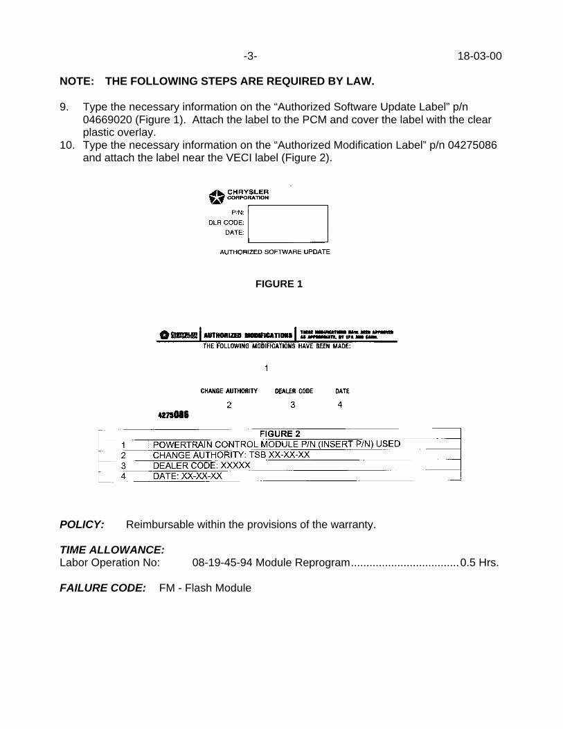
-3- 18-03-00
NOTE: THE FOLLOWING STEPS ARE REQUIRED BY LAW.
9. Type the necessary information on the “Authorized Software Update Label” p/n04669020 (Figure 1). Attach the label to the PCM and cover the label with the clearplastic overlay.
10. Type the necessary information on the “Authorized Modification Label” p/n 04275086and attach the label near the VECI label (Figure 2).
POLICY: Reimbursable within the provisions of the warranty.
TIME ALLOWANCE:Labor Operation No: 08-19-45-94 Module Reprogram...................................0.5 Hrs.
FAILURE CODE: FM - Flash Module
FIGURE 1

Form TSB-003 Rev. 1.08 February 3, 2000
NUMBER: 18-04-00
GROUP: Vehicle Performance
DATE: Jun. 2, 2000
SUBJECT:Erroneous MIL With P0441 – EVAP PURGE FLOW MONITOR FAILURE
OVERVIEW:This bulletin involves selectively erasing and reprogramming the Powertrain ControlModule (PCM) with new software.
MODELS:2001 (PT) PT Cruiser
NOTE: THIS INFORMATION APPLIES TO VEHICLES EQUIPPED WITH A 2.4LENGINE AND AUTOMATIC TRANSAXLE BUILT PRIOR TO MAY 2, 2000(MDH 0502XX), AND WITH MANUAL TRANSAXLE BUILT PRIOR TO MAY 12,2000 (MDH 0512XX).
SYMPTOM/CONDITION:The customer will notice a Malfunction Indicator Lamp (MIL) illumination with no vehicleperformance issues. Diagnostic Trouble Code (DTC) P0441 and an error in the PurgeFlow Monitor OBDII test will be seen when checked with the Diagnostic Scan Tool (DRBIII7).
DIAGNOSIS:Using the Mopar Diagnostic System (MDS2) and or the Diagnostic Scan Tool (DRB III7)with the appropriate Diagnostic Procedures, verify all engine/transmission systems arefunctioning as designed. If other Diagnostic Trouble Codes (DTC's) are present, recordthem on the repair order and repair as necessary before proceeding further with thisbulletin. If only DTC P0441 was present and the vehicle is within the build range listedabove, perform the Repair Procedure.
NOTE: WHENEVER A POWERTRAIN CONTROL MODULE (PCM) IS REPLACED,THE SOFTWARE OF THE REPLACEMENT CONTROLLER MUST BEVERIFIED FOR THE LATEST REVISION LEVEL. USE THE FLASHPROCEDURE TO UPDATE REPLACED CONTROLLERS AS NECESSARY.
PARTS REQUIRED:1 04669020 Label, Authorized Software Update1 04275086 Label, Authorized Modification
EQUIPMENT REQUIRED:1 CH6000 Scan Tool (DRB III)1 CH7035 General Purpose Interface Bus Cable (GPIB)1 CH7000/7001 J1962 Cable1 MDS2
This bulletin is supplied as technical information only and is not an authorization for repair. No part of this publication may be reproduced, stored in a retrieval system, ortransmitted, in any form or by any means, electronic, mechanical, photocopying, recording, or otherwise, without written permission of DaimlerChrysler Corporation.

18-04-00 -2-
NOTE: THE MDS2 AND DRB III ARE REQUIRED TO PERFORM PART OF THISREPAIR. THE MDS2 SYSTEM MUST BE OPERATING AT CIS CD2059 ORHIGHER.
REPAIR PROCEDURE:1. Log onto the MDS2 system.2. Connect the MDS2 (Mopar Diagnostic System) and DRB III (Scan Tool) to the
vehicle and switch the ignition key to “ON”.3. Use the arrow keys and select #2 CONNECT TO MDS1 OR MDS2 on the DRB III
MAIN MENU SCREEN.4. Use the arrow keys and select #2 RUN MDS2 APPLICATION on the DRB III MAIN
MENU SCREEN.
NOTE: ONCE MDS2, DRB III, AND VEHICLE COMMUNICATION HAS BEENESTABLISHED, THE "CANNOT READ VIN FROM DRB III" MESSAGE (ONTHE MDS2) WILL BE REPLACED BY THE VEHICLE VIN. PRESS THE “OK”BUTTON ON THE MDS2 TO REQUEST A MDS2 SESSION FOR THEVEHICLE VIN INDICATED. PRESS THE “OK” BUTTON WHEN ASKED TOBEGIN SESSION.
5. Push the FLASH tab on the MDS2.
NOTE: A MESSAGE MAY APPEAR THAT INDICATES NO UPDATES AREAVAILABLE. IF THIS OCCURS, MAKE SURE YOUR DIAGNOSTICEQUIPMENT IS OPERATING AT THE LATEST SOFTWARE LEVEL ASLISTED EARLIER IN THIS BULLETIN. IF THE LATEST SOFTWARE ISINSTALLED, AND NO UPDATES ARE AVAILABLE, ANOTHER VEHICLECONDITION EXISTS THAT WILL REQUIRE FURTHER INVESTIGATION.
6. Select READ PART NUMBERS FROM VEHICLE and click SHOW UPDATES on theMDS2.
NOTE: A MESSAGE MAY APPEAR THAT INDICATES NO UPDATES AREAVAILABLE. IF THIS OCCURS, MAKE SURE YOUR DIAGNOSTICEQUIPMENT IS OPERATING AT THE LATEST SOFTWARE LEVEL ASLISTED EARLIER IN THIS BULLETIN. IF THE LATEST SOFTWARE ISINSTALLED, AND NO UPDATES ARE AVAILABLE, ANOTHER VEHICLECONDITION EXISTS THAT WILL REQUIRE FURTHER INVESTIGATION.
7. Select the new software part number with the light pen and click UPDATECONTROLLER SOFTWARE.
8. The MDS2 and DRB III will prompt for any operator action needed during theremainder of the reprogramming process.

-3- 18-04-00
NOTE: THE FOLLOWING STEPS ARE REQUIRED BY LAW.
9. Type the necessary information on the “Authorized Software Update Label” p/n04669020 (Figure 1). Attach the label to the PCM and cover the label with the clearplastic overlay.
10. Type the necessary information on the “Authorized Modification Label” p/n 04275086and attach the label near the VECI label (Figure 2).
POLICY: Reimbursable within the provisions of the warranty.
TIME ALLOWANCE:Labor Operation No: 08-19-45-92 Module Reprogram...................................0.5 Hrs.
FAILURE CODE: FM - Flash Module
FIGURE 1

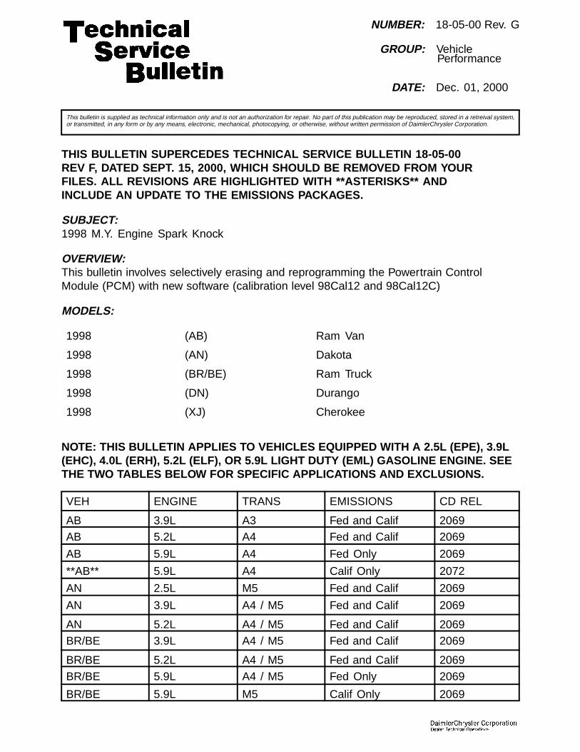
NUMBER: 18-05-00 Rev. G
GROUP: VehiclePerformance
DATE: Dec. 01, 2000
This bulletin is supplied as technical information only and is not an authorization for repair. No part of this publication may be reproduced, stored in a retreival system,or transmitted, in any form or by any means, electronic, mechanical, photocopying, or otherwise, without written permission of DaimlerChrysler Corporation.
THIS BULLETIN SUPERCEDES TECHNICAL SERVICE BULLETIN 18-05-00REV F, DATED SEPT. 15, 2000, WHICH SHOULD BE REMOVED FROM YOURFILES. ALL REVISIONS ARE HIGHLIGHTED WITH **ASTERISKS** ANDINCLUDE AN UPDATE TO THE EMISSIONS PACKAGES.
SUBJECT:1998 M.Y. Engine Spark Knock
OVERVIEW:This bulletin involves selectively erasing and reprogramming the Powertrain ControlModule (PCM) with new software (calibration level 98Cal12 and 98Cal12C)
MODELS:
1998 (AB) Ram Van
1998 (AN) Dakota
1998 (BR/BE) Ram Truck
1998 (DN) Durango
1998 (XJ) Cherokee
NOTE: THIS BULLETIN APPLIES TO VEHICLES EQUIPPED WITH A 2.5L (EPE), 3.9L(EHC), 4.0L (ERH), 5.2L (ELF), OR 5.9L LIGHT DUTY (EML) GASOLINE ENGINE. SEETHE TWO TABLES BELOW FOR SPECIFIC APPLICATIONS AND EXCLUSIONS.
VEH ENGINE TRANS EMISSIONS CD REL
AB 3.9L A3 Fed and Calif 2069AB 5.2L A4 Fed and Calif 2069
AB 5.9L A4 Fed Only 2069
**AB** 5.9L A4 Calif Only 2072
AN 2.5L M5 Fed and Calif 2069
AN 3.9L A4 / M5 Fed and Calif 2069
AN 5.2L A4 / M5 Fed and Calif 2069
BR/BE 3.9L A4 / M5 Fed and Calif 2069
BR/BE 5.2L A4 / M5 Fed and Calif 2069
BR/BE 5.9L A4 / M5 Fed Only 2069
BR/BE 5.9L M5 Calif Only 2069
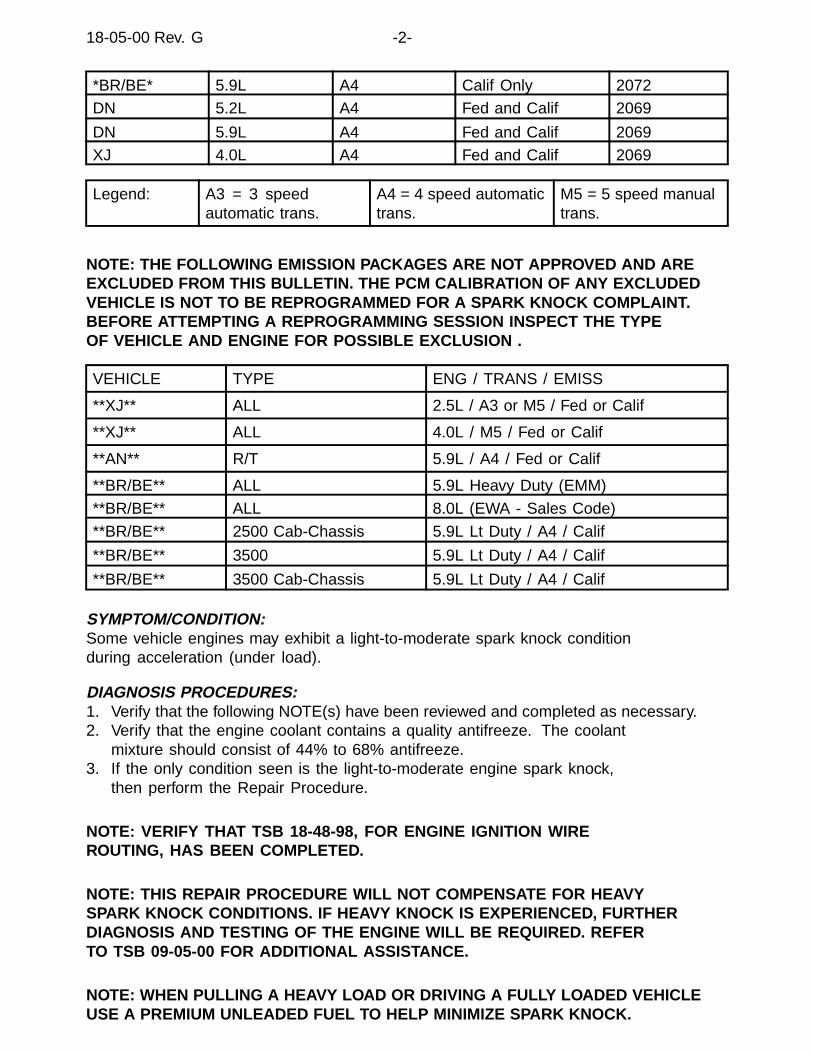
18-05-00 Rev. G -2-
*BR/BE* 5.9L A4 Calif Only 2072DN 5.2L A4 Fed and Calif 2069
DN 5.9L A4 Fed and Calif 2069XJ 4.0L A4 Fed and Calif 2069
Legend: A3 = 3 speedautomatic trans.
A4 = 4 speed automatictrans.
M5 = 5 speed manualtrans.
NOTE: THE FOLLOWING EMISSION PACKAGES ARE NOT APPROVED AND AREEXCLUDED FROM THIS BULLETIN. THE PCM CALIBRATION OF ANY EXCLUDEDVEHICLE IS NOT TO BE REPROGRAMMED FOR A SPARK KNOCK COMPLAINT.BEFORE ATTEMPTING A REPROGRAMMING SESSION INSPECT THE TYPEOF VEHICLE AND ENGINE FOR POSSIBLE EXCLUSION .
VEHICLE TYPE ENG / TRANS / EMISS
**XJ** ALL 2.5L / A3 or M5 / Fed or Calif
**XJ** ALL 4.0L / M5 / Fed or Calif
**AN** R/T 5.9L / A4 / Fed or Calif
**BR/BE** ALL 5.9L Heavy Duty (EMM)
**BR/BE** ALL 8.0L (EWA - Sales Code)
**BR/BE** 2500 Cab-Chassis 5.9L Lt Duty / A4 / Calif
**BR/BE** 3500 5.9L Lt Duty / A4 / Calif
**BR/BE** 3500 Cab-Chassis 5.9L Lt Duty / A4 / Calif
SYMPTOM/CONDITION:Some vehicle engines may exhibit a light-to-moderate spark knock conditionduring acceleration (under load).
DIAGNOSIS PROCEDURES:1. Verify that the following NOTE(s) have been reviewed and completed as necessary.2. Verify that the engine coolant contains a quality antifreeze. The coolant
mixture should consist of 44% to 68% antifreeze.3. If the only condition seen is the light-to-moderate engine spark knock,
then perform the Repair Procedure.
NOTE: VERIFY THAT TSB 18-48-98, FOR ENGINE IGNITION WIREROUTING, HAS BEEN COMPLETED.
NOTE: THIS REPAIR PROCEDURE WILL NOT COMPENSATE FOR HEAVYSPARK KNOCK CONDITIONS. IF HEAVY KNOCK IS EXPERIENCED, FURTHERDIAGNOSIS AND TESTING OF THE ENGINE WILL BE REQUIRED. REFERTO TSB 09-05-00 FOR ADDITIONAL ASSISTANCE.
NOTE: WHEN PULLING A HEAVY LOAD OR DRIVING A FULLY LOADED VEHICLEUSE A PREMIUM UNLEADED FUEL TO HELP MINIMIZE SPARK KNOCK.
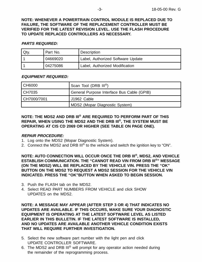
-3- 18-05-00 Rev. G
NOTE: WHENEVER A POWERTRAIN CONTROL MODULE IS REPLACED DUE TOFAILURE, THE SOFTWARE OF THE REPLACEMENT CONTROLLER MUST BEVERIFIED FOR THE LATEST REVISION LEVEL. USE THE FLASH PROCEDURETO UPDATE REPLACED CONTROLLERS AS NECESSARY.
PARTS REQUIRED:
Qty. Part No. Description
1 04669020 Label, Authorized Software Update
1 04275086 Label, Authorized Modification
EQUIPMENT REQUIRED:
CH6000 Scan Tool (DRB III®)
CH7035 General Purpose Interface Bus Cable (GPIB)
CH7000/7001 J1962 Cable
MDS2 (Mopar Diagnostic System)
NOTE: THE MDS2 AND DRB III ® ARE REQUIRED TO PERFORM PART OF THISREPAIR, WHEN USING THE MDS2 AND THE DRB III ®, THE SYSTEM MUST BEOPERATING AT CIS CD 2069 OR HIGHER (SEE TABLE ON PAGE ONE).
REPAIR PROCEDURE:1. Log onto the MDS2 (Mopar Diagnostic System).2. Connect the MDS2 and DRB III® to the vehicle and switch the ignition key to “ON”.
NOTE: AUTO CONNECTION WILL OCCUR ONCE THE DRB III ®, MDS2, AND VEHICLEESTABLISH COMMUNICATION. THE “CANNOT READ VIN FROM DRB III ®” MESSAGE(ON THE MDS2) WILL BE REPLACED BY THE VEHICLE VIN. PRESS THE “OK”BUTTON ON THE MDS2 TO REQUEST A MDS2 SESSION FOR THE VEHICLE VININDICATED. PRESS THE “OK”BUTTON WHEN ASKED TO BEGIN SESSION.
3. Push the FLASH tab on the MDS2.4. Select READ PART NUMBERS FROM VEHICLE and click SHOW
UPDATES on the MDS2.
NOTE: A MESSAGE MAY APPEAR (AFTER STEP 3 OR 4) THAT INDICATES NOUPDATES ARE AVAILABLE. IF THIS OCCURS, MAKE SURE YOUR DIAGNOSTICEQUIPMENT IS OPERATING AT THE LATEST SOFTWARE LEVEL AS LISTEDEARLIER IN THIS BULLETIN. IF THE LATEST SOFTWARE IS INSTALLED,AND NO UPDATES ARE AVAILABLE ANOTHER VEHICLE CONDITION EXISTSTHAT WILL REQUIRE FURTHER INVESTIGATION.
5. Select the new software part number with the light pen and clickUPDATE CONTROLLER SOFTWARE.
6. The MDS2 and DRB III® will prompt for any operator action needed duringthe remainder of the reprogramming process.

18-05-00 Rev. G -4-
NOTE: DUE TO THE PCM REPROGRAMMING PROCEDURE, A DTC MAYBE SET IN OTHER MODULES (EATX, BCM, MIC, SKIM, ETC.) WITHIN THEVEHICLE, IF SO EQUIPPED. SOME DTC’S MAY CAUSE THE MIL TO ILLUMINATE.ALL DTC’S RELATE TO A LOSS OF COMMUNICATIONS WITH THE MODULETHAT IS BEING REPROGRAMMED. CHECK ALL MODULES, RECORD THEFAULTS, AND ERASE THESE FAULTS PRIOR TO RETURNING THE VEHICLETO THE CUSTOMER. ERASE ANY FAULTS IN THE PCM ONLY AFTER ALLOTHER MODULES HAVE HAD THEIR FAULTS ERASED.
NOTE: THE FOLLOWING STEPS ARE REQUIRED BY LAW.
7. Type the necessary information on the “Authorized Software Update Label” p/n 04669020(Fig. 1). Attach the label to the PCM and cover the label with the clear plastic overlay.
Fig. 1 AUTHORIZED SOFTWARE UPDATE LABEL
8. Type the necessary information on the “Authorized Modification Label” p/n04275086 and attach the label near the VECI label (Fig. 2).
Fig. 2 AUTHORIZED MODIFICATION LABEL
1 - POWERTRAIN CONTROL MODULE P/N (INSERT P/N) USED
2 - CHANGE AUTHORITY: TSB XX-XX-XX
3 - DEALER CODE: XXXXX
4 - DATE: XX-XX-XX

-5- 18-05-00 Rev. G
POLICY:Reimbursable within the provisions of the warranty.
TIME ALLOWANCE:
Labor Operation No:
08-19-44-92 Reprogram PCM 0.5 Hrs.
FAILURE CODE: Could be one or more
FM Flash Module


NUMBER: 18-06-00 Rev. C
GROUP: VehiclePerformance
DATE: Dec. 01, 2000
This bulletin is supplied as technical information only and is not an authorization for repair. No part of this publication may be reproduced, stored in a retreival system,or transmitted, in any form or by any means, electronic, mechanical, photocopying, or otherwise, without written permission of DaimlerChrysler Corporation.
THIS BULLETIN SUPERCEDES TECHNICAL SERVICE BULLETIN 18-06-00REV B, DATED SEPT. 15, 2000, WHICH SHOULD BE REMOVED FROM YOURFILES. ALL REVISIONS ARE HIGHLIGHTED WITH **ASTERISKS** ANDINCLUDE AN UPDATE TO THE EMISSIONS PACKAGES.
SUBJECT:1999 M.Y. Engine Spark Knock
OVERVIEW:This bulletin involves selectively erasing and reprogramming the Powertrain Control Module(PCM) with new software (calibration level 99Cal16B, 99Cal 17, and 99Cal17A)
MODELS:
1999 (AB) Ram Van
1999 (AN) Dakota
1999 (BR/BE) Ram Truck
1999 (DN) Durango
NOTE: THIS BULLETIN APPLIES TO VEHICLES EQUIPPED WITH A 3.9L (EHC),5.2L (ELF), OR 5.9L LIGHT DUTY (EML) GASOLINE ENGINE. SEE THE TWOTABLES BELOW FOR SPECIFIC APPLICATIONS AND EXCLUSIONS.
VEH ENGINE TRANS EMISSIONS CD REL
AB 3.9L A3 Fed and Calif 2069
**AB** 5.2L A4 Fed and Calif 2072
**AB** 5.9L A4 Fed Only 2072
AN 3.9L A4 / M5 Fed and Calif 2069
**AN** 5.2L A4 / M5 Calif Only 2069
**AN** 5.2L A4 / M5 Fed Only 2072
BR/BE 3.9L A4 / M5 Fed and Calif 2069
*BR/BE* 5.2L A4 / M5 Fed and Calif 2072
*BR/BE* 5.9L M5 Fed and Calif 2072
*BR/BE 5.9L A4 Fed Only 2072
DN 5.2L A4 Calif Only 2069

18-06-00 Rev. C -2-
**DN** 5.2L A4 Fed Only 2072
DN 5.9L A4 Fed and Calif 2069
Legend: A3 = 3 speedautomatic trans.
A4 = 4 speed automatictrans.
M5 = 5 speed manualtrans.
NOTE: THE FOLLOWING EMISSION PACKAGES ARE NOT APPROVED AND AREEXCLUDED FROM THIS BULLETIN. THE PCM CALIBRATION OF ANY EXCLUDEDVEHICLE IS NOT TO BE REPROGRAMMED FOR A SPARK KNOCK COMPLAINT.BEFORE ATTEMPTING A REPROGRAMMING SESSION INSPECT THE TYPEOF VEHICLE AND ENGINE FOR POSSIBLE EXCLUSION .
VEHICLE TYPE ENG / TRANS / EMISS
**AN** ALL 2.5L / M5 / Fed and Calif
**AN** R/T 5.9L / A4 / Fed and Calif
**BR/BE** ALL 5.9L Heavy Duty (EMM)
**BR/BE** ALL 8.0L (EWA - Sales Code)
**BR/BE** 2500 Cab-Chassis 5.9L Lt Duty / A4 or M5 / Fed
**BR/BE** 2500 Cab-Chassis 5.9L Lt Duty / A4 / Calif
**BR/BE** 3500 5.9L Lt Duty / A4 or M5 / Calif
**BR/BE** 3500 Cab-Chassis 5.9L Lt Duty / A4 or M5 / Calif
SYMPTOM/CONDITION:Some vehicle engines may exhibit a light-to-moderate spark knock conditionduring acceleration (under load).
DIAGNOSIS PROCEDURES:1. Verify that the following NOTE(s) have been reviewed and completed as necessary.2. Verify that the engine coolant contains a quality antifreeze. The coolant
mixture should consist of 44% to 68% antifreeze.3. If the only condition seen is the light-to-moderate engine spark knock,
then perform the Repair Procedure.
NOTE: VERIFY THAT TSB 18-48-98, FOR ENGINE IGNITION WIREROUTING, HAS BEEN COMPLETED.
NOTE: THIS REPAIR PROCEDURE WILL NOT COMPENSATE FOR HEAVYSPARK KNOCK CONDITIONS. IF HEAVY KNOCK IS EXPERIENCED, FURTHERDIAGNOSIS AND TESTING OF THE ENGINE WILL BE REQUIRED. REFERTO TSB 09-05-00 FOR ADDITIONAL ASSISTANCE.
NOTE: WHEN PULLING A HEAVY LOAD OR DRIVING A FULLY LOADED VEHICLEUSE A PREMIUM UNLEADED FUEL TO HELP MINIMIZE SPARK KNOCK.
NOTE: WHENEVER A POWERTRAIN CONTROL MODULE IS REPLACED DUE TOFAILURE, THE SOFTWARE OF THE REPLACEMENT CONTROLLER MUST BE

-3- 18-06-00 Rev. C
VERIFIED FOR THE LATEST REVISION LEVEL. USE THE FLASH PROCEDURETO UPDATE REPLACED CONTROLLERS AS NECESSARY.
PARTS REQUIRED:
Qty. Part No. Description
1 04669020 Label, Authorized Software Update
1 04275086 Label, Authorized Modification
EQUIPMENT REQUIRED:
CH6000 Scan Tool (DRB III®)
CH7035 General Purpose Interface Bus Cable (GPIB)
CH7000/7001 J1962 Cable
MDS2 (Mopar Diagnostic System)
NOTE: THE MDS2 AND DRB III ® ARE REQUIRED TO PERFORM PART OF THISREPAIR, WHEN USING THE MDS2 AND THE DRB III ®, THE SYSTEM MUST BEOPERATING AT CIS CD 2069 OR HIGHER (SEE TABLE ON PAGE ONE).
REPAIR PROCEDURE:1. Log onto the MDS2 (Mopar Diagnostic System).2. Connect the MDS2 and DRB III® to the vehicle and switch the ignition key to “ON”.
NOTE: AUTO CONNECTION WILL OCCUR ONCE THE DRB III ®, MDS2, AND VEHICLEESTABLISH COMMUNICATION. THE “CANNOT READ VIN FROM DRB III ®” MESSAGE(ON THE MDS2) WILL BE REPLACED BY THE VEHICLE VIN. PRESS THE “OK”BUTTON ON THE MDS2 TO REQUEST A MDS2 SESSION FOR THE VEHICLE VININDICATED. PRESS THE “OK”BUTTON WHEN ASKED TO BEGIN SESSION.
3. Push the FLASH tab on the MDS2.4. Select READ PART NUMBERS FROM VEHICLE and click SHOW
UPDATES on the MDS2.
NOTE: A MESSAGE MAY APPEAR (AFTER STEP 3 OR 4) THAT INDICATES NOUPDATES ARE AVAILABLE. IF THIS OCCURS, MAKE SURE YOUR DIAGNOSTICEQUIPMENT IS OPERATING AT THE LATEST SOFTWARE LEVEL AS LISTEDEARLIER IN THIS BULLETIN. IF THE LATEST SOFTWARE IS INSTALLED,AND NO UPDATES ARE AVAILABLE ANOTHER VEHICLE CONDITION EXISTSTHAT WILL REQUIRE FURTHER INVESTIGATION.
5. Select the new software part number with the light pen and clickUPDATE CONTROLLER SOFTWARE.
6. The MDS2 and DRB III® will prompt for any operator action needed duringthe remainder of the reprogramming process.
NOTE: DUE TO THE PCM REPROGRAMMING PROCEDURE, A DTC MAYBE SET IN OTHER MODULES (EATX, BCM, MIC, SKIM, ETC.) WITHIN THE

18-06-00 Rev. C -4-
VEHICLE, IF SO EQUIPPED. SOME DTC’S MAY CAUSE THE MIL TO ILLUMINATE.ALL DTC’S RELATE TO A LOSS OF COMMUNICATIONS WITH THE MODULETHAT IS BEING REPROGRAMMED. CHECK ALL MODULES, RECORD THEFAULTS, AND ERASE THESE FAULTS PRIOR TO RETURNING THE VEHICLETO THE CUSTOMER. ERASE ANY FAULTS IN THE PCM ONLY AFTER ALLOTHER MODULES HAVE HAD THEIR FAULTS ERASED.
NOTE: THE FOLLOWING STEPS ARE REQUIRED BY LAW.
7. Type the necessary information on the “Authorized Software Update Label” p/n 04669020(Fig. 1). Attach the label to the PCM and cover the label with the clear plastic overlay.
Fig. 1 AUTHORIZED SOFTWARE UPDATE LABEL
8. Type the necessary information on the “Authorized Modification Label” p/n04275086 and attach the label near the VECI label (Fig. 2).
Fig. 2 AUTHORIZED MODIFICATION LABEL
1 - POWERTRAIN CONTROL MODULE P/N (INSERT P/N) USED
2 - CHANGE AUTHORITY: TSB XX-XX-XX
3 - DEALER CODE: XXXXX
4 - DATE: XX-XX-XX
POLICY:Reimbursable within the provisions of the warranty.

-5- 18-06-00 Rev. C
TIME ALLOWANCE:
Labor Operation No:
08-19-44-92 Reprogram PCM 0.5 Hrs.
FAILURE CODE: Could be one or more
FM Flash Module

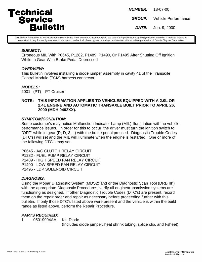
Form TSB-003 Rev. 1.08 February 3, 2000
NUMBER: 18-07-00
GROUP: Vehicle Performance
DATE: Jun. 9, 2000
SUBJECT:Erroneous MIL With P0645, P1282, P1489, P1490, Or P1495 After Shutting Off IgnitionWhile In Gear With Brake Pedal Depressed
OVERVIEW:This bulletin involves installing a diode jumper assembly in cavity 41 of the TransaxleControl Module (TCM) harness connector.
MODELS:2001 (PT) PT Cruiser
NOTE: THIS INFORMATION APPLIES TO VEHICLES EQUIPPED WITH A 2.0L OR2.4L ENGINE AND AUTOMATIC TRANSAXLE BUILT PRIOR TO APRIL 26,2000 (MDH 0402XX).
SYMPTOM/CONDITION:Some customer's may notice Malfunction Indicator Lamp (MIL) illumination with no vehicleperformance issues. In order for this to occur, the driver must turn the ignition switch to"OFF" while in gear (R, D, 3, L) with the brake pedal pressed. Diagnostic Trouble Codes(DTC's) will set and the MIL will illuminate when the engine is restarted. One or more ofthe following DTC's may set:
P0645 - A/C CLUTCH RELAY CIRCUITP1282 - FUEL PUMP RELAY CIRCUITP1489 - HIGH SPEED FAN RELAY CIRCUITP1490 - LOW SPEED FAN RELAY CIRCUITP1495 - LDP SOLENOID CIRCUIT
DIAGNOSIS:Using the Mopar Diagnostic System (MDS2) and or the Diagnostic Scan Tool (DRB III7)with the appropriate Diagnostic Procedures, verify all engine/transmission systems arefunctioning as designed. If other Diagnostic Trouble Codes (DTC's) are present, recordthem on the repair order and repair as necessary before proceeding further with thisbulletin. If only those DTC's listed above were present and the vehicle is within the buildrange as listed above, perform the Repair Procedure.
PARTS REQUIRED:1 05019994AA Kit, Diode
(Includes diode jumper, heat shrink tubing, splice clip, and I-sheet)
This bulletin is supplied as technical information only and is not an authorization for repair. No part of this publication may be reproduced, stored in a retrieval system, ortransmitted, in any form or by any means, electronic, mechanical, photocopying, recording, or otherwise, without written permission of DaimlerChrysler Corporation.

18-07-00 -2-
EQUIPMENT REQUIRED:1 NPN Electrical Tape1 NPN Soldering Iron1 NPN Rosin Core Solder1 05014738AA Crimping Tool
REPAIR PROCEDURE:1. Place the vehicle on a hoist, remove the air cleaner, disconnect and isolate the
negative battery cable.2. Raise the vehicle, remove the left (driver side) tire and splash shield. This will allow
access to the TCM connector.3. Remove the TCM harness connector from the TCM.
NOTE: DO NOT REMOVE THE TCM MODULE FROM THE VEHICLE.
4. Remove the harness dress cover from the connector to gain access for pin removal.5. Pull back the convolute for wire bundle access.6. Locate pin number 41 in the TCM connector. Using a terminal removal tool, remove
terminal 41 from the TCM connector.7. Cut the wire approximately 2 inches from the terminal. Discard the portion with the
terminal attached.8. Strip 1/2 inch of insulation from the harness end of the cut wire and place a piece of
heat shrink tubing from kit p/n 05019996AA over the wire.9. Twist the wires of the cut wire and diode assembly from kit p/n 05019996AA together.10. Use the splice clip from kit p/n 05019996AA and crimp the connection with crimping
tool p/n 05014738AA. Solder the connection with rosin core solder.11. Center the heat shrink tubing over the splice and heat until the tubing shrinks and glue
flows from both ends.12. Install the terminal into the TCM connector. Using electrical tape, tape the diode
assembly to the harness bundle.13. Reinstall the convolute tubing and connector dress cover. Tape the assembly for a
factory appearance.14. Reconnect the TCM connector and torque the bolt to 4 Nm + 0.5 Nm (35 in. lbs. + 5
in. lbs).15. Reconnect the battery and reinstall the air cleaner . Confirm the repair by using the
DRB III7. Observe the TRS sense circuit on the input/output screen of the DRB III7.The C1 (T41) switch position must be in the closed position when in park and openwhen in drive. If the screen displays open while in park, check for poor solderconnection or improper terminal placement.
16. Reinstall the splash shield and wheel.
POLICY: Reimbursable within the provisions of the warranty.
TIME ALLOWANCE:Labor Operation No: 08-90-65-98 Diode, EATX Harness Install ....................0.6 Hrs.
FAILURE CODE: P8 - New Part

Form TSB-003 Rev. 1.08 February 3, 2000
NUMBER: 18-08-00
GROUP: Vehicle Performance
DATE: June 23, 2000
THIS BULLETIN SUPERSEDES TECHNICAL SERVICE BULLETIN 18-03-99, DATEDFEB. 19, 1999, WHICH SHOULD BE REMOVED FROM YOUR FILES. ALL REVISIONSARE HIGHLIGHTED WITH **ASTERISKS** AND INCLUDE REVISED MODEL YEARS.
SUBJECT:Erroneous MIL Illumination Due To DTC P0107 – Map Sensor Voltage Too Low
OVERVIEW:This bulletin involves selectively erasing and reprogramming the JTEC Powertrain ControlModule (PCM) with new software (calibration change 96Cal18, 97Cal18 and 98Cal12).
**MODELS:****1996** – 1998 (AB) Ram Van**1996** – 1998 (AN) Dakota**1996** – 1998 (BR/BE) Ram Truck1998 (DN) Durango**1997** – 1998 (TJ) Wrangler**1996** – 1998 (XJ) Cherokee**1996** – 1998 (ZJ) Grand Cherokee
NOTE: THIS BULLETIN APPLIES TO VEHICLES EQUIPPED WITH GASOLINEENGINE.
SYMPTOM/CONDITION:Erroneous MIL illumination with DTC P0107 – MAP SENSOR VOLTAGE TOO LOW. Thismay occur during downhill decelerations at altitude or when performing off-roadmaneuvers when the engine is operating over 1500 rpm. The MIL illuminates due to themonitor running during incorrect parameters.
DIAGNOSIS:Using the Mopar Diagnostic System (MDS2) and or the Diagnostic Scan Tool (DRB III7),with the appropriate Diagnostic Procedures Manual, verify that all engine and transmissionsystems are functioning as designed. If Diagnostic Trouble Codes (DTC’s) are present,record them on the repair order and repair as necessary before proceeding further with thisbulletin. If no DTC’s are present, and the above symptom has been experienced, performthe Repair Procedure.
NOTE: WHENEVER A POWERTRAIN CONTROL MODULE (PCM) IS REPLACEDDUE TO FAILURE, THE SOFTWARE OF THE REPLACEMENT CONTROLLERMUST BE VERIFIED FOR THE LATEST REVISION LEVEL. USE THE FLASHPROCEDURE TO UPDATE REPLACED CONTROLLERS AS NECESSARY.
This bulletin is supplied as technical information only and is not an authorization for repair. No part of this publication may be reproduced, stored in a retrieval system, ortransmitted, in any form or by any means, electronic, mechanical, photocopying, recording, or otherwise, without written permission of DaimlerChrysler Corporation.

18-08-00 -2-
PARTS REQUIRED:1 04669020 Label, Authorized Software Update1 04275086 Label, Authorized Modification
EQUIPMENT REQUIRED:1 CH6000 Scan Tool (DRB III7)1 CH7035 General Purpose Interface Bus Cable (GPIB)1 CH7000/7001 J1962 Cable1 MDS2
NOTE: THE MDS2 AND DRB III77 ARE REQUIRED TO PERFORM PART OF THISREPAIR. WHEN USING THE MDS2 AND THE DRB III77, THE SYSTEM MUSTBE OPERATING AT CIS CD 2061 OR HIGHER.
REPAIR PROCEDURE:1. Log onto the MDS2 system.2. Connect the MDS2 and DRB III7 to the vehicle and switch the ignition key to “ON”.3. Use the arrow keys and select #2 CONNECT TO MDS2 on the DRB III7 MAIN MENU
SCREEN.4. Use the arrow keys and select #2 RUN MDS2 APPLICATION on the DRB III7 MAIN
MENU SCREEN.
NOTE: ONCE MDS2, DRB III77, AND VEHICLE COMMUNICATION HAS BEENESTABLISHED, THE “CANNOT READ VIN FROM DRB III77” MESSAGE (ONTHE MDS2) WILL BE REPLACED BY THE VEHICLE VIN. PRESS THE “OK”BUTTON ON THE MDS2 TO REQUEST A MDS2 SESSION FOR THEVEHICLE VIN INDICATED. PRESS THE “OK” BUTTON WHEN ASKED TOBEGIN SESSION.
5. Select the FLASH tab on the MDS2.
6. Select READ PART NUMBERS FROM VEHICLE and click SHOW UPDATES on theMDS2. Press the “OK” button.
NOTE: IN ABOVE STEPS #5 AND/OR #6, A MESSAGE MAY APPEAR THATINDICATES NO UPDATES ARE AVAILABLE. IF THIS OCCURS, MAKESURE YOUR DIAGNOSTIC EQUIPMENT IS OPERATING AT THE LATESTSOFTWARE LEVEL AS LISTED EARLIER IN THIS BULLETIN. IF THELATEST SOFTWARE IS INSTALLED, AND NO UPDATES ARE AVAILABLE,ANOTHER VEHICLE CONDITION EXISTS THAT WILL REQUIRE FURTHERINVESTIGATION.
7. Select the new software part number with the light pen and click UPDATECONTROLLER SOFTWARE.
8. The MDS2 and DRB III7 will prompt for any operator action needed during theremainder of the reprogramming process.
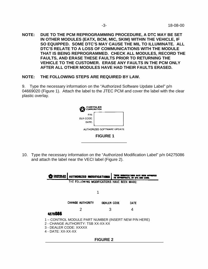
-3- 18-08-00
NOTE: DUE TO THE PCM REPROGRAMMING PROCEDURE, A DTC MAY BE SETIN OTHER MODULES (EATX, BCM, MIC, SKIM) WITHIN THE VEHICLE, IFSO EQUIPPED. SOME DTC’S MAY CAUSE THE MIL TO ILLUMINATE. ALLDTC’S RELATE TO A LOSS OF COMMUNICATIONS WITH THE MODULETHAT IS BEING REPROGRAMMED. CHECK ALL MODULES, RECORD THEFAULTS, AND ERASE THESE FAULTS PRIOR TO RETURNING THEVEHICLE TO THE CUSTOMER. ERASE ANY FAULTS IN THE PCM ONLYAFTER ALL OTHER MODULES HAVE HAD THEIR FAULTS ERASED.
NOTE: THE FOLLOWING STEPS ARE REQUIRED BY LAW.
9. Type the necessary information on the “Authorized Software Update Label” p/n04669020 (Figure 1). Attach the label to the JTEC PCM and cover the label with the clearplastic overlay.
FIGURE 1____________________
10. Type the necessary information on the “Authorized Modification Label” p/n 04275086and attach the label near the VECI label (Figure 2).
1
2 3 4
1 – CONTROL MODULE PART NUMBER (INSERT NEW P/N HERE)2 - CHANGE AUTHORITY: TSB XX-XX-XX3 - DEALER CODE: XXXXX4 - DATE: XX-XX-XX
FIGURE 2

18-08-00 -4-
POLICY: Reimbursable within the provisions of the warranty.
TIME ALLOWANCE:Labor Operation No: 08-19-42-93 ............................................................... 0.5 Hrs.
FAILURE CODE: FM – Flash Module
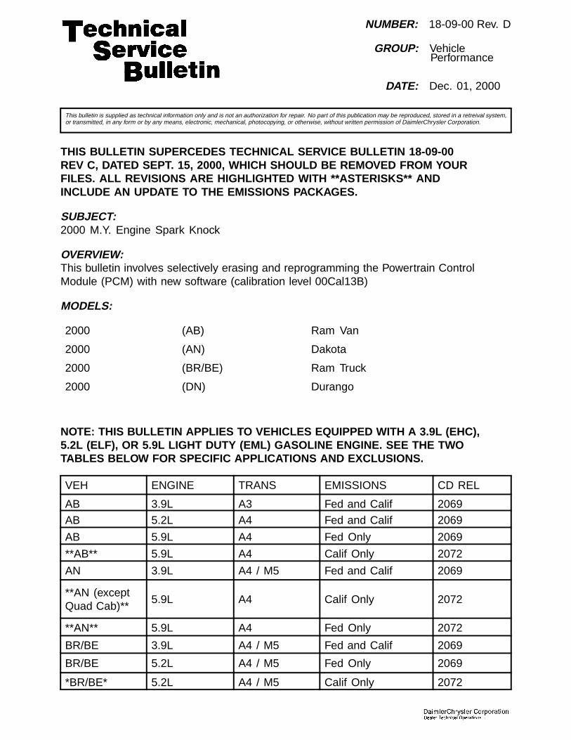
NUMBER: 18-09-00 Rev. D
GROUP: VehiclePerformance
DATE: Dec. 01, 2000
This bulletin is supplied as technical information only and is not an authorization for repair. No part of this publication may be reproduced, stored in a retreival system,or transmitted, in any form or by any means, electronic, mechanical, photocopying, or otherwise, without written permission of DaimlerChrysler Corporation.
THIS BULLETIN SUPERCEDES TECHNICAL SERVICE BULLETIN 18-09-00REV C, DATED SEPT. 15, 2000, WHICH SHOULD BE REMOVED FROM YOURFILES. ALL REVISIONS ARE HIGHLIGHTED WITH **ASTERISKS** ANDINCLUDE AN UPDATE TO THE EMISSIONS PACKAGES.
SUBJECT:2000 M.Y. Engine Spark Knock
OVERVIEW:This bulletin involves selectively erasing and reprogramming the Powertrain ControlModule (PCM) with new software (calibration level 00Cal13B)
MODELS:
2000 (AB) Ram Van
2000 (AN) Dakota
2000 (BR/BE) Ram Truck
2000 (DN) Durango
NOTE: THIS BULLETIN APPLIES TO VEHICLES EQUIPPED WITH A 3.9L (EHC),5.2L (ELF), OR 5.9L LIGHT DUTY (EML) GASOLINE ENGINE. SEE THE TWOTABLES BELOW FOR SPECIFIC APPLICATIONS AND EXCLUSIONS.
VEH ENGINE TRANS EMISSIONS CD REL
AB 3.9L A3 Fed and Calif 2069
AB 5.2L A4 Fed and Calif 2069
AB 5.9L A4 Fed Only 2069
**AB** 5.9L A4 Calif Only 2072
AN 3.9L A4 / M5 Fed and Calif 2069
**AN (exceptQuad Cab)**
5.9L A4 Calif Only 2072
**AN** 5.9L A4 Fed Only 2072
BR/BE 3.9L A4 / M5 Fed and Calif 2069
BR/BE 5.2L A4 / M5 Fed Only 2069
*BR/BE* 5.2L A4 / M5 Calif Only 2072

18-09-00 Rev. D -2-
BR/BE 5.9L A4 / M5 Fed Only 2069*BR/BE 5.9L A4 / M5 Calif Only 2072
DN (4x2) 5.2L A4 Fed and Calif 2069**DN** 5.9L A4 Fed Only 2072
Legend: A3 = 3 speedautomatic trans.
A4 = 4 speed automatictrans.
M5 = 5 speed manualtrans.
NOTE: THE FOLLOWING EMISSION PACKAGES ARE NOT APPROVED AND AREEXCLUDED FROM THIS BULLETIN. THE PCM CALIBRATION OF ANY EXCLUDEDVEHICLE IS NOT TO BE REPROGRAMMED FOR A SPARK KNOCK COMPLAINT.BEFORE ATTEMPTING A REPROGRAMMING SESSION INSPECT THE TYPEOF VEHICLE AND ENGINE FOR POSSIBLE EXCLUSION.
VEHICLE TYPE ENG / TRANS / EMISS
**AN** Regular Cab 2.5L / M5 / Fed and Calif
**BR/BE** ALL 5.9L Heavy Duty (EMM)
**BR/BE** ALL 8.0L (EWA - Sales Code)
**BR/BE** 3500 5.9L Lt Duty / A4 or M5 / Calif
**BR/BE** 3500 Cab-Chassis 5.9L Lt Duty / A4 or M5 / Calif
SYMPTOM/CONDITION:Some vehicle engines may exhibit a light-to-moderate spark knock conditionduring acceleration (under load).
DIAGNOSIS PROCEDURES:1. Verify that the following NOTE(s) have been reviewed and completed as necessary.2. Verify that the engine coolant contains a quality antifreeze. The coolant
mixture should consist of 44% to 68% antifreeze.3. If the only condition seen is the light-to-moderate engine spark knock,
then perform the Repair Procedure.
NOTE: WHEN PULLING A HEAVY LOAD OR DRIVING A FULLY LOADED VEHICLEUSE A PREMIUM UNLEADED FUEL TO HELP MINIMIZE SPARK KNOCK.
NOTE: WHENEVER A POWERTRAIN CONTROL MODULE IS REPLACED DUE TOFAILURE, THE SOFTWARE OF THE REPLACEMENT CONTROLLER MUST BEVERIFIED FOR THE LATEST REVISION LEVEL. USE THE FLASH PROCEDURETO UPDATE REPLACED CONTROLLERS AS NECESSARY.
PARTS REQUIRED:
Qty. Part No. Description
1 04669020 Label, Authorized Software Update
1 04275086 Label, Authorized Modification

-3- 18-09-00 Rev. D
EQUIPMENT REQUIRED:
CH6000 Scan Tool (DRB III®)
CH7035 General Purpose Interface Bus Cable (GPIB)
CH7000/7001 J1962 Cable
MDS2 (Mopar Diagnostic System)
NOTE: THE MDS2 AND DRB III ® ARE REQUIRED TO PERFORM PART OF THISREPAIR, WHEN USING THE MDS2 AND THE DRB III ®, THE SYSTEM MUST BEOPERATING AT CIS CD 2069 OR HIGHER (SEE TABLE ON PAGE ONE).
REPAIR PROCEDURE:1. Log onto the MDS2 (Mopar Diagnostic System).2. Connect the MDS2 and DRB III® to the vehicle and switch the ignition key to “ON”.
NOTE: AUTO CONNECTION WILL OCCUR ONCE THE DRB III ®, MDS2, AND VEHICLEESTABLISH COMMUNICATION. THE “CANNOT READ VIN FROM DRB III ®” MESSAGE(ON THE MDS2) WILL BE REPLACED BY THE VEHICLE VIN. PRESS THE “OK”BUTTON ON THE MDS2 TO REQUEST A MDS2 SESSION FOR THE VEHICLE VININDICATED. PRESS THE “OK”BUTTON WHEN ASKED TO BEGIN SESSION.
3. Push the FLASH tab on the MDS2.4. Select READ PART NUMBERS FROM VEHICLE and click SHOW
UPDATES on the MDS2.
NOTE: A MESSAGE MAY APPEAR (AFTER STEP 3 OR 4) THAT INDICATES NOUPDATES ARE AVAILABLE. IF THIS OCCURS, MAKE SURE YOUR DIAGNOSTICEQUIPMENT IS OPERATING AT THE LATEST SOFTWARE LEVEL AS LISTEDEARLIER IN THIS BULLETIN. IF THE LATEST SOFTWARE IS INSTALLED,AND NO UPDATES ARE AVAILABLE ANOTHER VEHICLE CONDITION EXISTSTHAT WILL REQUIRE FURTHER INVESTIGATION.
5. Select the new software part number with the light pen and clickUPDATE CONTROLLER SOFTWARE.
6. The MDS2 and DRB III® will prompt for any operator action needed duringthe remainder of the reprogramming process.
NOTE: DUE TO THE PCM REPROGRAMMING PROCEDURE, A DTC MAYBE SET IN OTHER MODULES (EATX, BCM, MIC, SKIM, ETC.) WITHIN THEVEHICLE, IF SO EQUIPPED. SOME DTC’S MAY CAUSE THE MIL TO ILLUMINATE.ALL DTC’S RELATE TO A LOSS OF COMMUNICATIONS WITH THE MODULETHAT IS BEING REPROGRAMMED. CHECK ALL MODULES, RECORD THEFAULTS, AND ERASE THESE FAULTS PRIOR TO RETURNING THE VEHICLETO THE CUSTOMER. ERASE ANY FAULTS IN THE PCM ONLY AFTER ALLOTHER MODULES HAVE HAD THEIR FAULTS ERASED.
NOTE: THE FOLLOWING STEPS ARE REQUIRED BY LAW.

18-09-00 Rev. D -4-
7. Type the necessary information on the “Authorized Software Update Label” p/n 04669020(Fig. 1). Attach the label to the PCM and cover the label with the clear plastic overlay.
Fig. 1 AUTHORIZED SOFTWARE UPDATE LABEL
8. Type the necessary information on the “Authorized Modification Label” p/n04275086 and attach the label near the VECI label (Fig. 2).
Fig. 2 AUTHORIZED MODIFICATION LABEL
1 - POWERTRAIN CONTROL MODULE P/N (INSERT P/N) USED
2 - CHANGE AUTHORITY: TSB XX-XX-XX
3 - DEALER CODE: XXXXX
4 - DATE: XX-XX-XX
POLICY:Reimbursable within the provisions of the warranty.
TIME ALLOWANCE:
Labor Operation No:
08-19-44-92 Reprogram PCM 0.5 Hrs.

-5- 18-09-00 Rev. D
FAILURE CODE: Could be one or more
FM Flash Module


Form TSB-003 Rev. 1.08 February 3, 2000
NUMBER: 18-10-00
GROUP: Vehicle Performance
DATE: Jul. 28, 2000
SUBJECT:No Response From TCM When Using Some Generic Scan Tools
OVERVIEW:This bulletin involves selectively erasing and reprogramming the Transmission ControlModule (TCM) with new software.
MODELS:2000 (GS) Chrysler Voyager (European Market)2000 (JA) Cirrus/Stratus/Breeze2000 (JX) Sebring Convertible2000 (NS) Town & Country/Caravan/Voyager2000 (PR) Prowler
NOTE: THIS INFORMATION APPLIES TO VEHICLES EQUIPPED WITH A 41TE/AEOR 42LE AUTOMATIC TRANSAXLE BUILT PRIOR TO THE FOLLOWINGDATES:
MODEL DATE/MDHGS OCT. 22, 1999 (MDH1022XX)JA OCT. 18, 1999 (MDH1018XX)JX OCT. 18, 1999 (MDH1018XX)NS OCT. 22, 1999 (MDH1022XX)PR OCT. 28, 1999 (MDH1028XX)
DISCUSSION:Models built prior to the dates in the above table may not respond properly to diagnosticrequests from some aftermarket generic scan tools. In these cases, the aftermarketgeneric scan tool may indicate that the Transmission Control Module (TCM) is notresponding. This may lead to unnecessary diagnostic procedures and or replacement ofgood TCM's.
NOTE: THE DRB III , MDS2, AND D.A.R.T. WORK PROPERLY WITH TCMCOMMUNICATION.
NOTE: WHENEVER A TRANSMISSION CONTROL MODULE (TCM) IS REPLACED,THE SOFTWARE OF THE REPLACEMENT CONTROLLER MUST BEVERIFIED FOR THE LATEST REVISION LEVEL. USE THE FLASHPROCEDURE TO UPDATE REPLACED CONTROLLERS AS NECESSARY.
PARTS REQUIRED:1 04669020 Label, Authorized Software Update1 04275086 Label, Authorized Modification
This bulletin is supplied as technical information only and is not an authorization for repair. No part of this publication may be reproduced, stored in a retrieval system, ortransmitted, in any form or by any means, electronic, mechanical, photocopying, recording, or otherwise, without written permission of DaimlerChrysler Corporation.

18-10-00 -2-
EQUIPMENT REQUIRED:1 CH6000 Scan Tool (DRB III)1 CH7035 General Purpose Interface Bus Cable (GPIB)1 CH7000/7001 J1962 Cable1 MDS2
NOTE: THE MDS2 AND DRB III ARE REQUIRED TO PERFORM PART OF THISREPAIR. THE MDS2 SYSTEM MUST BE OPERATING AT CIS CD2063 ORHIGHER.
REPAIR PROCEDURE:1. Log onto the MDS2 system.2. Connect the MDS2 (Mopar Diagnostic System) and DRB III (Scan Tool) to the
vehicle and switch the ignition key to “ON”.3. Use the arrow keys and select #2 CONNECT TO MDS1 OR MDS2 on the DRB III
MAIN MENU SCREEN.4. Use the arrow keys and select #2 RUN MDS2 APPLICATION on the DRB III MAIN
MENU SCREEN.
NOTE: ONCE MDS2, DRB III, AND VEHICLE COMMUNICATION HAS BEENESTABLISHED, THE "CANNOT READ VIN FROM DRB III" MESSAGE (ONTHE MDS2) WILL BE REPLACED BY THE VEHICLE VIN. PRESS THE “OK”BUTTON ON THE MDS2 TO REQUEST A MDS2 SESSION FOR THEVEHICLE VIN INDICATED. PRESS THE “OK” BUTTON WHEN ASKED TOBEGIN SESSION.
5. Push the FLASH tab on the MDS2.
NOTE: A MESSAGE MAY APPEAR THAT INDICATES NO UPDATES AREAVAILABLE. IF THIS OCCURS, MAKE SURE YOUR DIAGNOSTICEQUIPMENT IS OPERATING AT THE LATEST SOFTWARE LEVEL ASLISTED EARLIER IN THIS BULLETIN. IF THE LATEST SOFTWARE ISINSTALLED, AND NO UPDATES ARE AVAILABLE, ANOTHER VEHICLECONDITION EXISTS THAT WILL REQUIRE FURTHER INVESTIGATION.
6. Select READ PART NUMBERS FROM VEHICLE and click SHOW UPDATES on theMDS2.
NOTE: A MESSAGE MAY APPEAR THAT INDICATES NO UPDATES AREAVAILABLE. IF THIS OCCURS, MAKE SURE YOUR DIAGNOSTICEQUIPMENT IS OPERATING AT THE LATEST SOFTWARE LEVEL ASLISTED EARLIER IN THIS BULLETIN. IF THE LATEST SOFTWARE ISINSTALLED, AND NO UPDATES ARE AVAILABLE, ANOTHER VEHICLECONDITION EXISTS THAT WILL REQUIRE FURTHER INVESTIGATION.
7. Select the new software part number with the light pen and click UPDATECONTROLLER SOFTWARE.

-3- 18-10-00
8. The MDS2 and DRB III will prompt for any operator action needed during theremainder of the reprogramming process.
NOTE: THE FOLLOWING STEPS ARE REQUIRED BY LAW.
9. Type the necessary information on the “Authorized Software Update Label” p/n04669020 (Figure 1). Attach the label to the PCM and cover the label with the clearplastic overlay.
10. Type the necessary information on the “Authorized Modification Label” p/n 04275086and attach the label near the VECI label (Figure 2).
1
2 3 4
1 - TRANSMISSION CONTROL MODULE P/N (INSERT P/N) USED2 - CHANGE AUTHORITY: TSB XX-XX-XX3 - DEALER CODE: XXXXX4 - DATE: XX-XX-XX
FIGURE 2
FIGURE 1

18-10-00 -4-
POLICY: Reimbursable within the provisions of the warranty.
TIME ALLOWANCE:Labor Operation No: 08-19-51-91 Module Reprogram...................................0.5 Hrs.
FAILURE CODE: FM - Flash Module

Form TSB-003 Rev. 1.08 February 3, 2000
NUMBER: 18-11-00
GROUP: Vehicle Performance
DATE: Jul. 28, 2000
SUBJECT:Low Voltage Clutch Protection - Added DTC - P1714 Low Battery Voltage
OVERVIEW:This bulletin involves selectively erasing and reprogramming the Transmission ControlModule (TCM) with new software.
MODELS:1999 (FJ) Avenger/Sebring1999 (GS) Chrysler Voyager (European Market)1999 (JA) Cirrus/Stratus/Breeze1999 (JX) Sebring Convertible1999 (LH) Concorde/Intrepid/LHS/300M1999 (NS) Town & Country/Caravan/Voyager1999 (PR) Prowler
NOTE: THIS INFORMATION APPLIES TO VEHICLES EQUIPPED WITH A 41TE/AEOR 42LE AUTOMATIC TRANSAXLE BUILT PRIOR TO:
MODEL DATE/MDHGS/JA/JX/LH/NS JAN. 1, 1999 (MDH 0101XX)PR NOV. 18, 1998 (MDH1118XX)FJ JAN. 11, 1999 (MDH0111XX)
DISCUSSION:Operation of vehicles with low battery voltage may result in the transaxle overdrive clutchbecoming distressed. Conditions such as an inoperative charging system or excessvoltage drop to the TCM circuits may be causes for low voltage. The software released bythis Technical Service Bulletin provides protection to the overdrive clutch and adds a newDTC - P1714 LOW BATTERY VOLTAGE for these models. Diagnostic proceduresrelating to P1714 are attached for your reference.
NOTE: WHENEVER A TRANSMISSION CONTROL MODULE (TCM) IS REPLACED,THE SOFTWARE OF THE REPLACEMENT CONTROLLER MUST BEVERIFIED FOR THE LATEST REVISION LEVEL. USE THE FLASHPROCEDURE TO UPDATE REPLACED CONTROLLERS AS NECESSARY.
PARTS REQUIRED:1 04669020 Label, Authorized Software Update1 04275086 Label, Authorized Modification
This bulletin is supplied as technical information only and is not an authorization for repair. No part of this publication may be reproduced, stored in a retrieval system, ortransmitted, in any form or by any means, electronic, mechanical, photocopying, recording, or otherwise, without written permission of DaimlerChrysler Corporation.

18-11-00 -2-
EQUIPMENT REQUIRED:1 CH6000 Scan Tool (DRB III)1 CH7035 General Purpose Interface Bus Cable (GPIB)1 CH7000/7001 J1962 Cable1 CH7010 J1962 MMC Cable1 MDS2
NOTE: THE MDS2 AND DRB III ARE REQUIRED TO PERFORM PART OF THISREPAIR. THE MDS2 SYSTEM MUST BE OPERATING AT CIS CD2063 ORHIGHER.
REPAIR PROCEDURE:1. Log onto the MDS2 system.2. Connect the MDS2 (Mopar Diagnostic System) and DRB III (Scan Tool) to the
vehicle and switch the ignition key to “ON”.3. Use the arrow keys and select #2 CONNECT TO MDS1 OR MDS2 on the DRB III
MAIN MENU SCREEN.4. Use the arrow keys and select #2 RUN MDS2 APPLICATION on the DRB III MAIN
MENU SCREEN.
NOTE: ONCE MDS2, DRB III, AND VEHICLE COMMUNICATION HAS BEENESTABLISHED, THE "CANNOT READ VIN FROM DRB III" MESSAGE (ONTHE MDS2) WILL BE REPLACED BY THE VEHICLE VIN. PRESS THE “OK”BUTTON ON THE MDS2 TO REQUEST A MDS2 SESSION FOR THEVEHICLE VIN INDICATED. PRESS THE “OK” BUTTON WHEN ASKED TOBEGIN SESSION.
5. Push the FLASH tab on the MDS2.
NOTE: A MESSAGE MAY APPEAR THAT INDICATES NO UPDATES AREAVAILABLE. IF THIS OCCURS, MAKE SURE YOUR DIAGNOSTICEQUIPMENT IS OPERATING AT THE LATEST SOFTWARE LEVEL ASLISTED EARLIER IN THIS BULLETIN. IF THE LATEST SOFTWARE ISINSTALLED, AND NO UPDATES ARE AVAILABLE, ANOTHER VEHICLECONDITION EXISTS THAT WILL REQUIRE FURTHER INVESTIGATION.
6. Select READ PART NUMBERS FROM VEHICLE and click SHOW UPDATES on theMDS2.
NOTE: A MESSAGE MAY APPEAR THAT INDICATES NO UPDATES AREAVAILABLE. IF THIS OCCURS, MAKE SURE YOUR DIAGNOSTICEQUIPMENT IS OPERATING AT THE LATEST SOFTWARE LEVEL ASLISTED EARLIER IN THIS BULLETIN. IF THE LATEST SOFTWARE ISINSTALLED, AND NO UPDATES ARE AVAILABLE, ANOTHER VEHICLECONDITION EXISTS THAT WILL REQUIRE FURTHER INVESTIGATION.

-3- 18-11-00
7. Select the new software part number with the light pen and click UPDATECONTROLLER SOFTWARE.
8. The MDS2 and DRB III will prompt for any operator action needed during theremainder of the reprogramming process.
NOTE: THE FOLLOWING STEPS ARE REQUIRED BY LAW.
9. Type the necessary information on the “Authorized Software Update Label” p/n04669020 (Figure 1). Attach the label to the PCM and cover the label with the clearplastic overlay.
10. Type the necessary information on the “Authorized Modification Label” p/n 04275086and attach the label near the VECI label (Figure 2).
1
2 3 4
1 - TRANSMISSION CONTROL MODULE P/N (INSERT P/N) USED2 - CHANGE AUTHORITY: TSB XX-XX-XX3 - DEALER CODE: XXXXX4 - DATE: XX-XX-XX
FIGURE 2
FIGURE 1

18-11-00 -4-
POLICY: Reimbursable within the provisions of the warranty.
TIME ALLOWANCE:Labor Operation No: 08-19-51-90 Module Reprogram...................................0.5 Hrs.
FAILURE CODE: FM - Flash Module
Symptom:P1714-LOW BATTERY VOLTAGE
When Monitored and Set Condition:
P1714-LOW BATTERY VOLTAGE
When Monitored: With the engine running and the TCM has closed the Transmission Control Relay.
Set Condition: If battery voltage at TCM Transmission Control Relay Output Sense circuit is lessthan 10.0 volts for 15 seconds. *P-1714 generally indicates a gradually fallingbattery voltage or resistive connections to the TCM.
Possible CausesRELATED CHARGING SYSTEM DTCSINTERMITTENT WIRING AND CONNECTORSFUSED B+ CIRCUIT OPEN OR HIGH RESISTANCEGROUND CIRCUIT OPEN OR HIGH RESISTANCETRANS CONTROL RELAY OUTPUT TO TCM OPEN OR HIGH RESISTANCETRANSMISSION CONTROL RELAY OPEN OR HIGH RESISTANCETCM - LOW BATTERY VOLTAGE

-5- 18-11-00
P1714-LOW BATTERY VOLTAGE - ContinuedTEST ACTION APPLICABILITY1 NOTE: Low fluid level can be the cause of many Transmission problems. If the fluid
level is low, locate and repair the leak then check and adjust the fluid level per theService Information.NOTE: Always perform diagnostics with a fully charged battery to avoid falsesymptoms.With the DRBIII ® , read the engine DTC’s. Check and repair all engine DTC’s prior toperforming Transmission Symptom Diagnostics.With the DRBIII ® , read Transmission DTC’s. Record all DTC’s and 1 Trip Failures.NOTE: Diagnose 1 Trip Failures as a fully matured DTC.Using the wiring diagram/schematic as a guide, inspect the wiring and connectors. Repair asnecessary.Perform the Shift Lever Position Test. If the test does not pass, refer to Symptom test for P0705Check Shifter Signal.For Gear Ratio DTC’s, check and record all CVI’s.Most DTC’s set on start up but some must be set by driving the vehicle such that all diagnosticmonitors have run.NOTE: Verify flash level of Transmission Control Module. Some problems arecorrected by software upgrades to the Transmission Control Module.NOTE: Check for applicable TSB’s related to the symptom.Perform this procedure prior to Symptom diagnosis.Continue - Go To 2
All
2 With the DRBIII ® , read the PCM DTC’s.Are any Charging System related DTC’s stored in the PCM?Yes - Refer to the Charging System category and repair any PCM Charging System DTC’s, beforetesting DTC P1714. NOTE: After repairing the PCM charging system DTC’s, perform theTransmission Verification test to verify the transmission was not damaged.Perform 41TE TRANSMISSION VERIFICATION TEST - VER 1.No - Go To 3
All
3 NOTE: Generator, battery, and charging system must be fully functional beforeperforming this test.With the DRBIII ® , read Transmission DTC’s.With the DRBIII ® , Check the STARTS SINCE SET counter.Note: This counter only applies to the last DTC set.Is the Starts Since Set counter for P1714 set at 0?Yes - Go To 4No - Go To 9
All

18-11-00 -6-
P1714-LOW BATTERY VOLTAGE - ContinuedTEST ACTION APPLICABILITY4 Turn the ignition off to the lock position.
Disconnect the TCM harness connector.Remove the Transmission Control Relay.Note: Check connectors - Clean/repair as necessary.Connect a jumper wire between cavity Fused B+ and cavity Transmission Control Relay Output.Ignition on, engine not running.Using a 12-volt test light connected to ground, check the Fused B+ circuit in the TCM harnessconnector.NOTE: The test light must illuminate brightly. Compare the brightness to that of adirect connection to the battery.Does the test light illuminate brightly?Yes - Go To 5No - Repair the Fused B+ circuit for an open or high resistance. If the fuse is open make sure tocheck for a short to ground.Perform 41TE TRANSMISSION VERIFICATION TEST - VER 1.
All
5 Turn the ignition off to the lock position.Disconnect the TCM harness connector.Note: Check connectors - Clean/repair as necessary.Using a 12-volt test light connected to 12-volts, check the ground circuits in the TCM harnessconnector.NOTE: The test light must illuminate brightly. Compare the brightness to that of adirect connection to the battery.Does the test light illuminate brightly at all ground circuits?Yes - Go To 6No - Repair the Ground circuit(s) for an open or high resistance.Perform 41TE TRANSMISSION VERIFICATION TEST - VER 1.
All
6 Turn the ignition off to the lock position.Disconnect the TCM harness connector.Remove the Transmission Control Relay.Note: Check connectors - Clean/repair as necessary.Connect a jumper wire between cavity Fused B+ and cavity Transmission Control Relay Output.Ignition on, engine not running.Using a 12-volt test light connected to ground, check both Transmission Control Relay Outputcircuits in the TCM harness connector.NOTE: The test light must illuminate brightly. Compare the brightness to that of adirect connection to the battery.Does the test light illuminate brightly?Yes - Go To 7No - Repair the Transmission Control Relay Output circuit for an open or high resistance.Perform 41TE TRANSMISSION VERIFICATION TEST - VER 1.
All
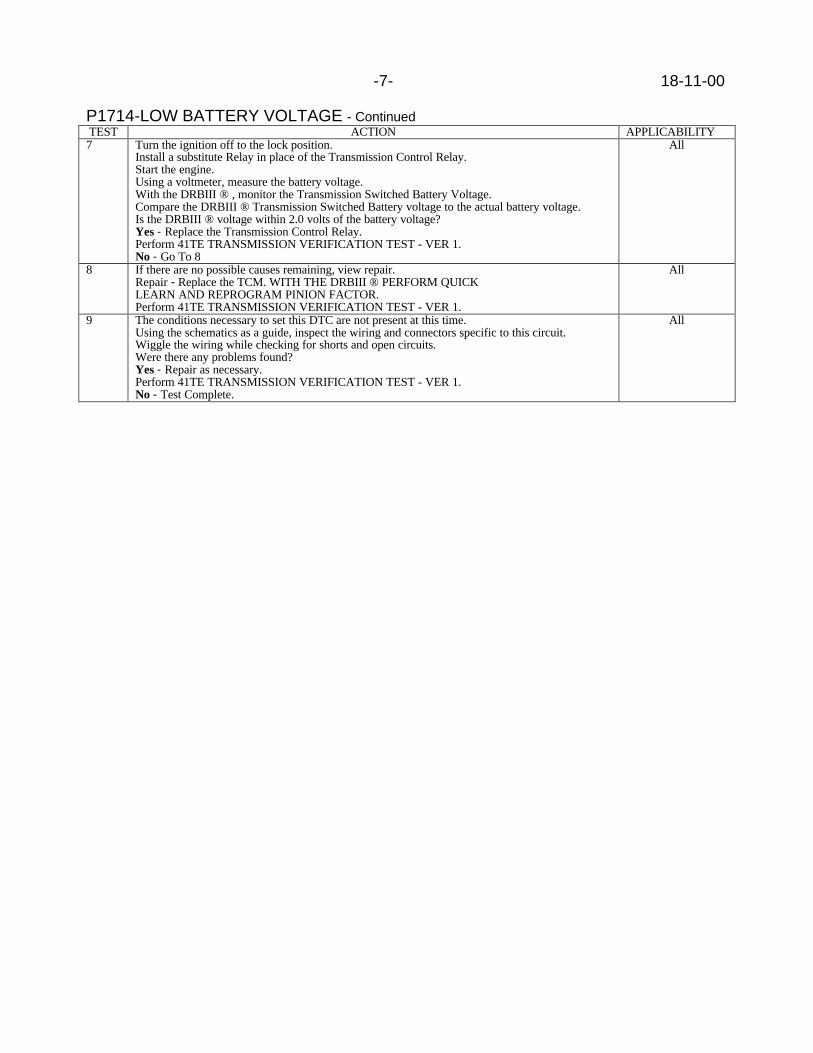
-7- 18-11-00
P1714-LOW BATTERY VOLTAGE - ContinuedTEST ACTION APPLICABILITY7 Turn the ignition off to the lock position.
Install a substitute Relay in place of the Transmission Control Relay.Start the engine.Using a voltmeter, measure the battery voltage.With the DRBIII ® , monitor the Transmission Switched Battery Voltage.Compare the DRBIII ® Transmission Switched Battery voltage to the actual battery voltage.Is the DRBIII ® voltage within 2.0 volts of the battery voltage?Yes - Replace the Transmission Control Relay.Perform 41TE TRANSMISSION VERIFICATION TEST - VER 1.No - Go To 8
All
8 If there are no possible causes remaining, view repair.Repair - Replace the TCM. WITH THE DRBIII ® PERFORM QUICKLEARN AND REPROGRAM PINION FACTOR.Perform 41TE TRANSMISSION VERIFICATION TEST - VER 1.
All
9 The conditions necessary to set this DTC are not present at this time.Using the schematics as a guide, inspect the wiring and connectors specific to this circuit.Wiggle the wiring while checking for shorts and open circuits.Were there any problems found?Yes - Repair as necessary.Perform 41TE TRANSMISSION VERIFICATION TEST - VER 1.No - Test Complete.
All

18-11-00 -8-
P1714-LOW BATTERY VOLTAGE - Continued
Verification Tests41TE TRANSMISSION VERIFICATION TEST - VER 1 APPLICABILITY
1. Connect the DRBIII ® to the Data Link Connector (DLC).2. Reconnect any disconnected components.3. With the DRBIII ® , erase all Transmission DTC’s, also erase the PCM DTC’s.4. NOTE: Erase DTC P0700 in the PCM to turn the Malfunction Indicator Lamp (MIL) off aftermaking Transmission repairs.5. With the DRBIII ® , display Transmission Temperature. Start and run the engine untilthe Transmission Temperature is HOT - above 43.33 C or 110 F.6. Check the Transmission Fluid and adjust if necessary. Refer to the Service informationfor the Fluid Fill procedure.7. NOTE: If the Transmission Control Module or Torque Converter has been replaced or ifthe Transmission has been repaired or replaced it is necessary to perform the DRBIII ®Quick Learn Procedure and reset the "Pinion Factor"8. NOTE: If the Torque Converter is replaced, or if a TCMis replaced on a vehicle whoseTorque Converter has less than 3750 miles and less than 360 minutes of PEMCC, then withthe DRBIII ® restart the TCC Break-In. This is in order to avoid possible shudder(APPLICABLE VEHICLES ONLY).9. Road test the vehicle. With the DRBIII ® , monitor the engine RPM. Make 15 to 20 1-2,2-3, 3-4 upshifts. Perform these shifts from a standing start to 45 MPH with a constantthrottle opening of 20 to 25 degrees.10. Below 25 MPH, make 5 to 8 wide open throttle kickdowns to 1st gear. Allow at least 5seconds each in 2nd and 3rd gear between each kickdown.11. For a specific DTC, drive the vehicle to the Symptom’s When Monitored/When Setconditions to verify the DTC repair.12. NOTE: Use the EATX OBDII Task Manager to run Good Trip time in each gear, this willconfirm the repair and to ensure that the DTC has not re-matured.13. Check for Diagnostic Trouble Codes (DTC’s) during the road test. If a DTC setsduring the road test , return to the Symptom list and perform the appropriate Symptom.Were there any Diagnostic Trouble Codes (DTCs) set during the road test?Yes - Refer to the Symptom List for appropriate Symptom(s).No - Repair is complete.
All

Form TSB-004 Rev. 1.06 February 3, 2000
NUMBER: 18-12-00
GROUP: Vehicle Performance
DATE: Aug. 11, 2000
SUBJECT:Revised MIL Feature For Customer OBDII I/M Readiness
MODELS:2001 (JR) Sebring Sedan/Stratus Sedan/Sebring Convertible2001 (PL) Neon2001 (PT) PT Cruiser2001 (RG) Chrysler Voyager (International Market)2001 (RS) Town & Country/Caravan/Voyager
NOTE: THIS TECHNICAL SERVICE BULLETIN WILL BE UPDATED AS OTHERMODELS INCORPORATE THIS FEATURE.
DISCUSSION:A new feature (Customer OBD Inspection/Maintenance (I/M) Readiness) which utilizes theOBD MIL (Malfunction Indicator Lamp) has been implemented to provide customers withthe capability to determine if their vehicle is "READY" for an I/M test.
NOTE: PASSING I/M READINESS MAY BE REQUIRED BY SOME STATES AS APRE-REQUISITE FOR VEHICLE REGISTRATION.
This change is reflected in the way the MIL illuminates during key "ON" (no crank/start) asfollows:
1. Switch ignition to the "ON" position. Do not crank or start the engine.
NOTE: IF THE ENGINE IS CRANKED OR STARTED, THE PROCEDURE MUST BERESTARTED FROM KEY "OFF".
2. The MIL will illuminate (bulb check) and will continue to illuminate for approximately15 seconds. After 15 seconds, one of the following two conditions will occur.
NOT READY FOR AN I/M TESTThe MIL will flash once per second for approximately 10 seconds and then return to a fullyIlluminated condition until the ignition is turned "OFF" or the engine is started.
READY FOR AN I/M TESTThe MIL will continue to illuminate until the ignition is turned "OFF" or the engine is started.
MIL functionality during normal (engine running) vehicle operation remains unchanged.
POLICY: Information Only
This bulletin is supplied as technical information only and is not an authorization for repair. No part of this publication may be reproduced, stored in a retrieval system, ortransmitted, in any form or by any means, electronic, mechanical, photocopying, recording, or otherwise, without written permission of DaimlerChrysler Corporation.


Form TSB-003 Rev. 1.08 February 3, 2000
NUMBER: 18-13-00
GROUP: Vehicle Performance
DATE: Aug. 25, 2000
SUBJECT:Idle Fluctuation And/Or Tip In Hesitation At Low Speed
OVERVIEW:This bulletin involves selectively erasing and reprogramming the Powertrain ControlModule (PCM) with new software.
MODELS:2000 (LH) Concorde/Intrepid/LHS/300M
NOTE: THIS INFORMATION APPLIES TO VEHICLES EQUIPPED WITH A 2.7LENGINE.
SYMPTOM/CONDITION:Some vehicles may exhibit idle fluctuation and/or tip in hesitation at low speed due to idlespeed calibration.
DIAGNOSIS:Using the Mopar Diagnostic System (MDS2) and or the Diagnostic Scan Tool (DRB III7)with the appropriate Diagnostic Procedures, verify all engine/transmission systems arefunctioning as designed. If other Diagnostic Trouble Codes (DTC's) are present, recordthem on the repair order and repair as necessary before proceeding further with thisbulletin. If the condition is explained by the customer and no other faults exist, perform theRepair Procedure.
NOTE: WHENEVER A POWERTRAIN CONTROL MODULE (PCM) IS REPLACED,THE SOFTWARE OF THE REPLACEMENT CONTROLLER MUST BEVERIFIED FOR THE LATEST REVISION LEVEL. USE THE FLASHPROCEDURE TO UPDATE REPLACED CONTROLLERS AS NECESSARY.
PARTS REQUIRED:1 04669020 Label, Authorized Software Update1 04275086 Label, Authorized Modification
EQUIPMENT REQUIRED:1 CH6000 Scan Tool (DRB III)1 CH7035 General Purpose Interface Bus Cable (GPIB)1 CH7000/7001 J1962 Cable1 MDS2
This bulletin is supplied as technical information only and is not an authorization for repair. No part of this publication may be reproduced, stored in a retrieval system, ortransmitted, in any form or by any means, electronic, mechanical, photocopying, recording, or otherwise, without written permission of DaimlerChrysler Corporation.

18-13-00 -2-
NOTE: THE MDS2 AND DRB III ARE REQUIRED TO PERFORM PART OF THISREPAIR. THE MDS2 SYSTEM MUST BE OPERATING AT CIS CD2065 ORHIGHER.
REPAIR PROCEDURE:1. Log onto the MDS2 system.2. Connect the MDS2 (Mopar Diagnostic System) and DRB III (Scan Tool) to the
vehicle and switch the ignition key to “ON”.3. Use the arrow keys and select #2 CONNECT TO MDS1 OR MDS2 on the DRB III
MAIN MENU SCREEN.4. Use the arrow keys and select #2 RUN MDS2 APPLICATION on the DRB III MAIN
MENU SCREEN.
NOTE: ONCE MDS2, DRB III, AND VEHICLE COMMUNICATION HAS BEENESTABLISHED, THE "CANNOT READ VIN FROM DRB III" MESSAGE (ONTHE MDS2) WILL BE REPLACED BY THE VEHICLE VIN. PRESS THE “OK”BUTTON ON THE MDS2 TO REQUEST A MDS2 SESSION FOR THEVEHICLE VIN INDICATED. PRESS THE “OK” BUTTON WHEN ASKED TOBEGIN SESSION.
5. Push the FLASH tab on the MDS2.
NOTE: A MESSAGE MAY APPEAR THAT INDICATES NO UPDATES AREAVAILABLE. IF THIS OCCURS, MAKE SURE YOUR DIAGNOSTICEQUIPMENT IS OPERATING AT THE LATEST SOFTWARE LEVEL ASLISTED EARLIER IN THIS BULLETIN. IF THE LATEST SOFTWARE ISINSTALLED, AND NO UPDATES ARE AVAILABLE, ANOTHER VEHICLECONDITION EXISTS THAT WILL REQUIRE FURTHER INVESTIGATION.
6. Select READ PART NUMBERS FROM VEHICLE and click SHOW UPDATES on theMDS2.
NOTE: A MESSAGE MAY APPEAR THAT INDICATES NO UPDATES AREAVAILABLE. IF THIS OCCURS, MAKE SURE YOUR DIAGNOSTICEQUIPMENT IS OPERATING AT THE LATEST SOFTWARE LEVEL ASLISTED EARLIER IN THIS BULLETIN. IF THE LATEST SOFTWARE ISINSTALLED, AND NO UPDATES ARE AVAILABLE, ANOTHER VEHICLECONDITION EXISTS THAT WILL REQUIRE FURTHER INVESTIGATION.
7. Select the new software part number with the light pen and click UPDATECONTROLLER SOFTWARE.
8. The MDS2 and DRB III will prompt for any operator action needed during theremainder of the reprogramming process.

-3- 18-13-00
NOTE: THE FOLLOWING STEPS ARE REQUIRED BY LAW.
9. Type the necessary information on the “Authorized Software Update Label” p/n04669020 (Figure 1). Attach the label to the PCM and cover the label with the clearplastic overlay.
10. Type the necessary information on the “Authorized Modification Label” p/n 04275086and attach the label near the VECI label (Figure 2).
POLICY: Reimbursable within the provisions of the warranty.
TIME ALLOWANCE:Labor Operation No: 08-19-45-97 Module Reprogram...................................0.5 Hrs.
FAILURE CODE: FM - Flash Module
FIGURE 1


Form TSB-003 Rev. 1.08 February 3, 2000
NUMBER: 18-14-00
GROUP: Vehicle Performance
DATE: Aug. 25, 2000
SUBJECT:4 To 3 Harsh Downshift In The 25 to 40 MPH Range
OVERVIEW:This bulletin involves selectively erasing and reprogramming the Transmission ControlModule (TCM) with new software.
MODELS:2000 (LH) Concorde/Intrepid/LHS/300M
NOTE: THIS INFORMATION APPLIES TO VEHICLES EQUIPPED WITH A 42LEAUTOMATIC TRANSAXLE BUILT PRIOR TO JAN. 12, 2000 (MDH0112XX).
SYMPTOM/CONDITION:Some vehicles may experience a harsh 4 to 3 downshift when accelerating in the 25 to 40mile per hour range.
DIAGNOSIS:Using the Mopar Diagnostic System (MDS2) and or the Diagnostic Scan Tool (DRB III7)with the appropriate Diagnostic Procedures Manual, verify all engine/transmission systemsare functioning as designed. If Diagnostic Trouble Codes (DTC's) are present, recordthem on the repair order and repair as necessary before proceeding further with thisbulletin. If the only condition described by the vehicle operator is a harsh 4 to 3 downshift,Perform The Repair Procedure.
NOTE: WHENEVER A TRANSMISSION CONTROL MODULE (TCM) IS REPLACED,THE SOFTWARE OF THE REPLACEMENT CONTROLLER MUST BEVERIFIED FOR THE LATEST REVISION LEVEL. USE THE FLASHPROCEDURE TO UPDATE REPLACED CONTROLLERS AS NECESSARY.
PARTS REQUIRED:1 04669020 Label, Authorized Software Update1 04275086 Label, Authorized Modification
EQUIPMENT REQUIRED:1 CH6000 Scan Tool (DRB III)1 CH7035 General Purpose Interface Bus Cable (GPIB)1 CH7000/7001 J1962 Cable1 MDS2
NOTE: THE MDS2 AND DRB III ARE REQUIRED TO PERFORM PART OF THISREPAIR. THE MDS2 SYSTEM MUST BE OPERATING AT CIS CD2065 ORHIGHER.
This bulletin is supplied as technical information only and is not an authorization for repair. No part of this publication may be reproduced, stored in a retrieval system, ortransmitted, in any form or by any means, electronic, mechanical, photocopying, recording, or otherwise, without written permission of DaimlerChrysler Corporation.

18-14-00 -2-
REPAIR PROCEDURE:1. Log onto the MDS2 system.2. Connect the MDS2 (Mopar Diagnostic System) and DRB III (Scan Tool) to the
vehicle and switch the ignition key to “ON”.3. Use the arrow keys and select #2 CONNECT TO MDS1 OR MDS2 on the DRB III
MAIN MENU SCREEN.4. Use the arrow keys and select #2 RUN MDS2 APPLICATION on the DRB III MAIN
MENU SCREEN.
NOTE: ONCE MDS2, DRB III, AND VEHICLE COMMUNICATION HAS BEENESTABLISHED, THE "CANNOT READ VIN FROM DRB III" MESSAGE (ONTHE MDS2) WILL BE REPLACED BY THE VEHICLE VIN. PRESS THE “OK”BUTTON ON THE MDS2 TO REQUEST A MDS2 SESSION FOR THEVEHICLE VIN INDICATED. PRESS THE “OK” BUTTON WHEN ASKED TOBEGIN SESSION.
5. Push the FLASH tab on the MDS2.
NOTE: A MESSAGE MAY APPEAR THAT INDICATES NO UPDATES AREAVAILABLE. IF THIS OCCURS, MAKE SURE YOUR DIAGNOSTICEQUIPMENT IS OPERATING AT THE LATEST SOFTWARE LEVEL ASLISTED EARLIER IN THIS BULLETIN. IF THE LATEST SOFTWARE ISINSTALLED, AND NO UPDATES ARE AVAILABLE, ANOTHER VEHICLECONDITION EXISTS THAT WILL REQUIRE FURTHER INVESTIGATION.
6. Select READ PART NUMBERS FROM VEHICLE and click SHOW UPDATES on theMDS2.
NOTE: A MESSAGE MAY APPEAR THAT INDICATES NO UPDATES AREAVAILABLE. IF THIS OCCURS, MAKE SURE YOUR DIAGNOSTICEQUIPMENT IS OPERATING AT THE LATEST SOFTWARE LEVEL ASLISTED EARLIER IN THIS BULLETIN. IF THE LATEST SOFTWARE ISINSTALLED, AND NO UPDATES ARE AVAILABLE, ANOTHER VEHICLECONDITION EXISTS THAT WILL REQUIRE FURTHER INVESTIGATION.
7. Select the new software part number with the light pen and click UPDATECONTROLLER SOFTWARE.
8. The MDS2 and DRB III will prompt for any operator action needed during theremainder of the reprogramming process.
NOTE: THE FOLLOWING STEPS ARE REQUIRED BY LAW.
9. Type the necessary information on the “Authorized Software Update Label” p/n04669020 (Figure 1). Attach the label to the PCM and cover the label with the clearplastic overlay.
10. Type the necessary information on the “Authorized Modification Label” p/n 04275086and attach the label near the VECI label (Figure 2).

-3- 18-14-00
1
2 3 4
1 - TRANSMISSION CONTROL MODULE P/N (INSERT P/N) USED2 - CHANGE AUTHORITY: TSB XX-XX-XX3 - DEALER CODE: XXXXX4 - DATE: XX-XX-XX
FIGURE 2
POLICY: Reimbursable within the provisions of the warranty.
TIME ALLOWANCE:Labor Operation No: 08-19-51-93 Module Reprogram...................................0.5 Hrs.
FAILURE CODE: FM - Flash Module
FIGURE 1


NUMBER: 18–015–00 Rev. A
GROUP: VehiclePerformance
DATE: Dec. 21, 2000
This bulletin is supplied as technical information only and is not an authorization for repair. No part of this publication may be reproduced, stored in a retreival system,or transmitted, in any form or by any means, electronic, mechanical, photocopying, or otherwise, without written permission of DaimlerChrysler Corporation.
THIS BULLETIN SUPERCEDES TECHNICAL SERVICE BULLETIN 18-015-00,DATED SEP. 08, 2000, WHICH SHOULD BE REMOVED FROM YOUR FILES.ALL REVISIONS ARE HIGHLIGHTED WITH **ASTERISKS** AND INCLUDEAN UPDATE TO THE VEHICLE MODEL YEARS.
SUBJECT:Driveability Enhancements For Winter Fuel Use And For Hard Starts
OVERVIEW:This bulletin involves selectively erasing and reprogramming the Cummins CM551Engine Control Module (ECM) with new software (calibration versions: 55T18, 57T11A,57T11B, 56T13, 59T6). There is no change to the JTEC PCM software.
MODELS:
**1998 - 2001 (BR/BE) Ram Truck**
NOTE: THIS BULLETIN APPLIES TO VEHICLES EQUIPPED WITH A 5.9L-24V DIESELENGINE BUILT BETWEEN ENGINE SERIAL NUMBERS 56419738 TO 56798357, WITHA DATE OF MANUFACTURE OF DEC. 16, 1997 TO NOV. 15, 2000. THIS INFORMATIONIS AVAILABLE ON THE ENGINE DATA PLATE, WHICH IS LOCATED ON THE LEFTSIDE OF THE ENGINE, AFFIXED TO THE SIDE OF THE TIMING GEAR HOUSING.
SYMPTOM/CONDITION:The customer may complain of poor driveability when winter fuel is used to power theengine. Or, the customer may complain of a hard or no-start condition, while the engine isat normal operating temperatures, when using any type of good quality diesel fuel.The poor driveability condition may occur only when either straight #1 diesel fuel isused or when other special cold climate winter blend fuels are in use.The no-start or long engine crank condition may occur when attempting to restartthe engine while the temperature of the engine is still close to its normal operatingtemperature. This hard hot restart condition may be experienced in all ambientclimates, but may be more of a concern in warmer ambient climates.
NOTE: IF TSB 18-024-00 HAS PREVIOUSLY BEEN PERFORMED TO THE VEHICLEIN QUESTION, THEN THE ECM SOFTWARE HAS ALREADY BEEN REVISEDWITH THE CORRECT CALIBRATION TO ADDRESS THE ABOVE CONDITION(S).THE ECM WILL NOT REQUIRE REPROGRAMMING.

18–015–00 Rev. A -2-
DIAGNOSIS PROCEDURES:Using the Mopar Diagnostic System (MDS2) and or the Diagnostic Scan Tool (DRBIII®), with the appropriate Diagnostic Procedures Manual, verify that all engine andtransmission systems are functioning as designed. If Diagnostic Trouble Codes(DTC’s) are present, record them on the repair order and repair as necessarybefore proceeding further with this bulletin. If no DTC’s are present, and the abovesymptom has been experienced, perform the Repair Procedure.
PARTS REQUIRED:
Qty. Part No. Description
1 04669020 Label, Authorized Software Update
1 04275086 Label, Authorized Modification
EQUIPMENT REQUIRED:
CH6000 Scan Tool (DRB III®)
CH7035 General Purpose Interface Bus Cable (GPIB)
CH7000/7001 J1962 Cable
MDS2 (Mopar Diagnostic System)
NOTE: THE MDS2 AND DRB III ® ARE REQUIRED TO PERFORM PART OFTHIS REPAIR, WHEN USING THE MDS2 AND THE DRB III ®, THE SYSTEMMUST BE OPERATING AT CIS CD 2073 OR HIGHER.
REPAIR PROCEDURE:1. Log onto the MDS2 (Mopar Diagnostic System).2. Connect the MDS2 and DRB III® to the vehicle and switch the ignition key to “ON”.
NOTE: AUTO CONNECTION WILL OCCUR ONCE THE DRB III ®, MDS2, AND VEHICLEESTABLISH COMMUNICATION. THE “CANNOT READ VIN FROM DRB III ®” MESSAGE(ON THE MDS2) WILL BE REPLACED BY THE VEHICLE VIN. PRESS THE “OK”BUTTON ON THE MDS2 TO REQUEST A MDS2 SESSION FOR THE VEHICLE VININDICATED. PRESS THE “OK”BUTTON WHEN ASKED TO BEGIN SESSION.
3. Push the FLASH tab on the MDS2.4. Select READ PART NUMBERS FROM VEHICLE and click SHOW
UPDATES on the MDS2.
NOTE: A MESSAGE MAY APPEAR (AFTER STEP 3 OR 4) THAT INDICATES NOUPDATES ARE AVAILABLE. IF THIS OCCURS, MAKE SURE YOUR DIAGNOSTICEQUIPMENT IS OPERATING AT THE LATEST SOFTWARE LEVEL AS LISTEDEARLIER IN THIS BULLETIN. IF THE LATEST SOFTWARE IS INSTALLED,AND NO UPDATES ARE AVAILABLE ANOTHER VEHICLE CONDITION EXISTSTHAT WILL REQUIRE FURTHER INVESTIGATION.
5. Select the new software part number with the light pen and clickUPDATE CONTROLLER SOFTWARE.
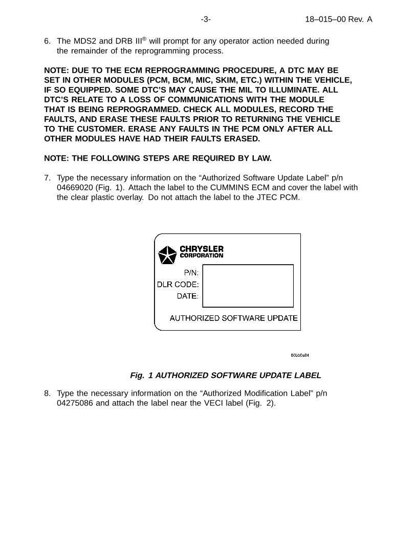
-3- 18–015–00 Rev. A
6. The MDS2 and DRB III® will prompt for any operator action needed duringthe remainder of the reprogramming process.
NOTE: DUE TO THE ECM REPROGRAMMING PROCEDURE, A DTC MAY BESET IN OTHER MODULES (PCM, BCM, MIC, SKIM, ETC.) WITHIN THE VEHICLE,IF SO EQUIPPED. SOME DTC’S MAY CAUSE THE MIL TO ILLUMINATE. ALLDTC’S RELATE TO A LOSS OF COMMUNICATIONS WITH THE MODULETHAT IS BEING REPROGRAMMED. CHECK ALL MODULES, RECORD THEFAULTS, AND ERASE THESE FAULTS PRIOR TO RETURNING THE VEHICLETO THE CUSTOMER. ERASE ANY FAULTS IN THE PCM ONLY AFTER ALLOTHER MODULES HAVE HAD THEIR FAULTS ERASED.
NOTE: THE FOLLOWING STEPS ARE REQUIRED BY LAW.
7. Type the necessary information on the “Authorized Software Update Label” p/n04669020 (Fig. 1). Attach the label to the CUMMINS ECM and cover the label withthe clear plastic overlay. Do not attach the label to the JTEC PCM.
Fig. 1 AUTHORIZED SOFTWARE UPDATE LABEL
8. Type the necessary information on the “Authorized Modification Label” p/n04275086 and attach the label near the VECI label (Fig. 2).

18–015–00 Rev. A -4-
Fig. 2 AUTHORIZED MODIFICATION LABEL
1 - POWERTRAIN CONTROL MODULE P/N (INSERT P/N) USED
2 - CHANGE AUTHORITY: TSB XX-XX-XX
3 - DEALER CODE: XXXXX
4 - DATE: XX-XX-XX
POLICY:Reimbursable within the provisions of the warranty.
TIME ALLOWANCE:
Labor Operation No:
08-19-45-90 Reprogram PCM 0.5 Hrs.
FAILURE CODE:
FM Flash Module

Form TSB-003 Rev. 1.08 February 3, 2000
NUMBER: 18-16-00
GROUP: Vehicle Performance
DATE: Sept. 15, 2000
SUBJECT:Poor A/C Or Engine Performance
OVERVIEW:This bulletin involves selectively erasing and reprogramming the Powertrain ControlModule (PCM) with new software.
MODELS:2001 (PL) Neon
NOTE: THIS INFORMATION APPLIES TO VEHICLES BUILT PRIOR TO AUGUST 28,2000 (MDH0828XX).
SYMPTOM/CONDITION:Some vehicles may exhibit one or more symptom/conditions as follows:
Poor A/C Performance In High Ambient TemperaturesDuring high under hood temperatures with the engine coolant temperature less than 100oC(212oF), the A/C compressor may repeatedly disengage due to high head pressure.Disengagement of the A/C compressor may continue until speeds of 40 Kph (25 Mph) ormore are reached.
Poor Engine Performance In City Traffic During High Ambient TemperaturesDuring high temperatures (greater than 35oC [95oF]) in stop and go traffic (at least 30minutes). Some vehicle may exhibit poor acceleration (0 to 40 Kph [0 to 25 Mph] in 20seconds) or experience difficulty exceeding 96 Kph (60 Mph). Cooling the engine correctsthe condition.
Engine Speed Undershoot Due To High DI FuelIn ambient conditions between 15oC and 26oC (60oF and 80oF) with the HVAC system setto A/C or defrost on an initial cold start. Some vehicles may exhibit an idle speed drop toapproximately 400 rpm on the first A/C compressor engagement. Later A/C engagementsare without occurrence. See TSB 14-08-97 dated Nov. 21, 1997 for a detailed explanationof High DI fuel.
DIAGNOSIS:Using the Mopar Diagnostic System (MDS2) and or the Diagnostic Scan Tool (DRB III7)with the appropriate Diagnostic Procedures, verify all engine/transmission systems arefunctioning as designed. If other Diagnostic Trouble Codes (DTC's) are present, recordthem on the repair order and repair as necessary before proceeding further with thisbulletin. If the condition(s) can be duplicated or is described by the customer, perform theRepair Procedure.
This bulletin is supplied as technical information only and is not an authorization for repair. No part of this publication may be reproduced, stored in a retrieval system, ortransmitted, in any form or by any means, electronic, mechanical, photocopying, recording, or otherwise, without written permission of DaimlerChrysler Corporation.

18-16-00 -2-
NOTE: WHENEVER A POWERTRAIN CONTROL MODULE (PCM) IS REPLACED,THE SOFTWARE OF THE REPLACEMENT CONTROLLER MUST BEVERIFIED FOR THE LATEST REVISION LEVEL. USE THE FLASHPROCEDURE TO UPDATE REPLACED CONTROLLERS AS NECESSARY.
PARTS REQUIRED:1 04669020 Label, Authorized Software Update1 04275086 Label, Authorized Modification
EQUIPMENT REQUIRED:1 CH6000 Scan Tool (DRB III)1 CH7035 General Purpose Interface Bus Cable (GPIB)1 CH7000/7001 J1962 Cable1 MDS2
NOTE: THE MDS2 AND DRB III ARE REQUIRED TO PERFORM PART OF THISREPAIR. THE MDS2 SYSTEM MUST BE OPERATING AT CIS CD2067 ORHIGHER.
REPAIR PROCEDURE:1. Log onto the MDS2 system.2. Connect the MDS2 (Mopar Diagnostic System) and DRB III (Scan Tool) to the
vehicle and switch the ignition key to “ON”.
NOTE: AUTO CONNECTION WILL OCCUR ONCE THE DRB III, MDS2 ANDVEHICLE ESTABLISH COMMUNICATION. THE "CANNOT READ VIN FROMDRB III" MESSAGE (ON THE MDS2) WILL BE REPLACED BY THE VEHICLEVIN. PRESS THE “OK” BUTTON ON THE MDS2 TO REQUEST A MDS2SESSION FOR THE VEHICLE VIN INDICATED. PRESS THE “OK” BUTTONWHEN ASKED TO BEGIN SESSION.
3. Push the FLASH tab on the MDS2.4. Select READ PART NUMBERS FROM VEHICLE and click SHOW UPDATES on the
MDS2.
NOTE: A MESSAGE MAY APPEAR (AFTER STEP 3 OR 4) THAT INDICATES NOUPDATES ARE AVAILABLE. IF THIS OCCURS, MAKE SURE YOURDIAGNOSTIC EQUIPMENT IS OPERATING AT THE LATEST SOFTWARELEVEL AS LISTED EARLIER IN THIS BULLETIN. IF THE LATESTSOFTWARE IS INSTALLED, AND NO UPDATES ARE AVAILABLE,ANOTHER VEHICLE CONDITION EXISTS THAT WILL REQUIRE FURTHERINVESTIGATION.
5. Select the new software part number with the light pen and click UPDATECONTROLLER SOFTWARE.
6. The MDS2 and DRB III will prompt for any operator action needed during theremainder of the reprogramming process.

-3- 18-16-00
NOTE: THE FOLLOWING STEPS ARE REQUIRED BY LAW.
7. Type the necessary information on the “Authorized Software Update Label” p/n04669020 (Figure 1). Attach the label to the PCM and cover the label with the clearplastic overlay.
8. Type the necessary information on the “Authorized Modification Label” p/n 04275086and attach the label near the VECI label (Figure 2).
POLICY: Reimbursable within the provisions of the warranty.
TIME ALLOWANCE:Labor Operation No: 08-19-45-98 Module Reprogram...................................0.5 Hrs.
FAILURE CODE: FM - Flash Module
FIGURE 1

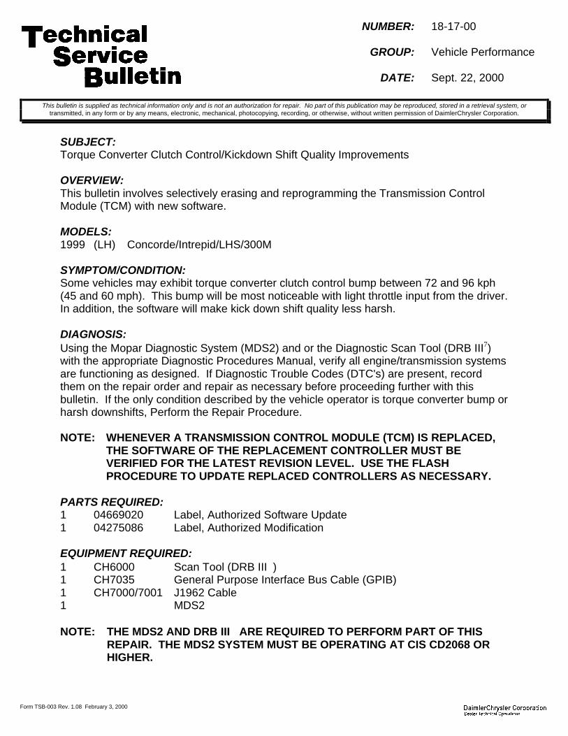
Form TSB-003 Rev. 1.08 February 3, 2000
NUMBER: 18-17-00
GROUP: Vehicle Performance
DATE: Sept. 22, 2000
SUBJECT:Torque Converter Clutch Control/Kickdown Shift Quality Improvements
OVERVIEW:This bulletin involves selectively erasing and reprogramming the Transmission ControlModule (TCM) with new software.
MODELS:1999 (LH) Concorde/Intrepid/LHS/300M
SYMPTOM/CONDITION:Some vehicles may exhibit torque converter clutch control bump between 72 and 96 kph(45 and 60 mph). This bump will be most noticeable with light throttle input from the driver.In addition, the software will make kick down shift quality less harsh.
DIAGNOSIS:Using the Mopar Diagnostic System (MDS2) and or the Diagnostic Scan Tool (DRB III7)with the appropriate Diagnostic Procedures Manual, verify all engine/transmission systemsare functioning as designed. If Diagnostic Trouble Codes (DTC's) are present, recordthem on the repair order and repair as necessary before proceeding further with thisbulletin. If the only condition described by the vehicle operator is torque converter bump orharsh downshifts, Perform the Repair Procedure.
NOTE: WHENEVER A TRANSMISSION CONTROL MODULE (TCM) IS REPLACED,THE SOFTWARE OF THE REPLACEMENT CONTROLLER MUST BEVERIFIED FOR THE LATEST REVISION LEVEL. USE THE FLASHPROCEDURE TO UPDATE REPLACED CONTROLLERS AS NECESSARY.
PARTS REQUIRED:1 04669020 Label, Authorized Software Update1 04275086 Label, Authorized Modification
EQUIPMENT REQUIRED:1 CH6000 Scan Tool (DRB III)1 CH7035 General Purpose Interface Bus Cable (GPIB)1 CH7000/7001 J1962 Cable1 MDS2
NOTE: THE MDS2 AND DRB III ARE REQUIRED TO PERFORM PART OF THISREPAIR. THE MDS2 SYSTEM MUST BE OPERATING AT CIS CD2068 ORHIGHER.
This bulletin is supplied as technical information only and is not an authorization for repair. No part of this publication may be reproduced, stored in a retrieval system, ortransmitted, in any form or by any means, electronic, mechanical, photocopying, recording, or otherwise, without written permission of DaimlerChrysler Corporation.

18-17-00 -2-
REPAIR PROCEDURE:1. Log onto the MDS2 system.2. Connect the MDS2 (Mopar Diagnostic System) and DRB III (Scan Tool) to the
vehicle and switch the ignition key to “ON”.
NOTE: AUTO CONNECTION WILL OCCUR ONCE THE DRB III, MDS2 ANDVEHICLE ESTABLISH COMMUNICATION. THE "CANNOT READ VIN FROMDRB III" MESSAGE (ON THE MDS2) WILL BE REPLACED BY THE VEHICLEVIN. PRESS THE “OK” BUTTON ON THE MDS2 TO REQUEST A MDS2SESSION FOR THE VEHICLE VIN INDICATED. PRESS THE “OK” BUTTONWHEN ASKED TO BEGIN SESSION.
3. Push the FLASH tab on the MDS2.4. Select READ PART NUMBERS FROM VEHICLE and click SHOW UPDATES on the
MDS2.
NOTE: A MESSAGE MAY APPEAR (AFTER STEP 3 OR 4) THAT INDICATES NOUPDATES ARE AVAILABLE. IF THIS OCCURS, MAKE SURE YOURDIAGNOSTIC EQUIPMENT IS OPERATING AT THE LATEST SOFTWARELEVEL AS LISTED EARLIER IN THIS BULLETIN. IF THE LATESTSOFTWARE IS INSTALLED, AND NO UPDATES ARE AVAILABLE,ANOTHER VEHICLE CONDITION EXISTS THAT WILL REQUIRE FURTHERINVESTIGATION.
5. Select the new software part number with the light pen and click UPDATECONTROLLER SOFTWARE.
6. The MDS2 and DRB III will prompt for any operator action needed during theremainder of the reprogramming process.
NOTE: THE FOLLOWING STEPS ARE REQUIRED BY LAW.
7. Type the necessary information on the “Authorized Software Update Label” p/n04669020 (Figure 1). Attach the label to the PCM and cover the label with the clearplastic overlay.
8. Type the necessary information on the “Authorized Modification Label” p/n 04275086and attach the label near the VECI label (Figure 2).
FIGURE 1

-3- 18-17-00
1
2 3 4
1 - TRANSMISSION CONTROL MODULE P/N (INSERT P/N) USED2 - CHANGE AUTHORITY: TSB XX-XX-XX3 - DEALER CODE: XXXXX4 - DATE: XX-XX-XX
FIGURE 2
POLICY: Reimbursable within the provisions of the warranty.
TIME ALLOWANCE:Labor Operation No: 08-19-51-94 Module Reprogram...................................0.5 Hrs.
FAILURE CODE: FM - Flash Module


Form TSB-003 Rev. 1.08 February 3, 2000
NUMBER: 18-18-00
GROUP: Vehicle Performance
DATE: Sept. 22, 2000
SUBJECT:Driveability Improvements/System Enhancements
OVERVIEW:This bulletin involves selectively erasing and reprogramming the Powertrain ControlModule (PCM) with new software.
MODELS:2001 (PT) PT Cruiser
NOTE: THIS INFORMATION APPLIES TO VEHICLES BUILT PRIOR TO AUGUST 22,2000 (MDH0822XX) EQUIPPED WITH A 2.4L ENGINE AND AUTOMATICTRANSAXLE.
SYMPTOM/CONDITION:Some vehicles may exhibit one or more symptom/conditions as follows:Poor acceleration or launch performance from standing starts with A/C "ON"Spark Knock At High Altitudes
Audible spark knock under high load at high altitude. An example of this is climbinga grade at high altitude with the accelerator close to (but not at) wide open throttle.
In addition, the following enhancements are included:Cruise Control
A tap down feature is added by using the "coast/set" lever. Tapping the"COAST/SET" button once will result in a 2 kph (1 mph) speed decrease. Eachtime the button is tapped, speed decreases.
Fuel EconomyOwners may gain 1 to 1 1/2 miles of fuel economy during highway operation.
Revised MIL Feature For Customer OBDII/IM ReadinessDetails of this feature are included in TSB 18-12-00 dated Aug. 11, 2000.
NOTE: THE OWNER OF THE VEHICLE SHOULD BE MADE AWARE OF THE ADDEDCRUISE CONTROL AND MIL FEATURE SINCE IT CHANGES THEOPERATION OF THEIR VEHICLE. ATTACHED ARE PAGES FROM THE 2001PT OWNER'S MANUAL (SECOND EDITION) THAT CAN BE COPIED ANDGIVEN TO OWNERS RECEIVING THIS UPDATE.
DIAGNOSIS:Using the Mopar Diagnostic System (MDS2) and or the Diagnostic Scan Tool (DRB III7)with the appropriate Diagnostic Procedures, verify all engine/transmission systems arefunctioning as designed. If other Diagnostic Trouble Codes (DTC's) are present, recordthem on the repair order and repair as necessary before proceeding further with thisbulletin. If the condition(s) can be duplicated or is described by the customer, perform theRepair Procedure.
This bulletin is supplied as technical information only and is not an authorization for repair. No part of this publication may be reproduced, stored in a retrieval system, ortransmitted, in any form or by any means, electronic, mechanical, photocopying, recording, or otherwise, without written permission of DaimlerChrysler Corporation.

18-18-00 -2-
NOTE: WHENEVER A POWERTRAIN CONTROL MODULE (PCM) IS REPLACED,THE SOFTWARE OF THE REPLACEMENT CONTROLLER MUST BEVERIFIED FOR THE LATEST REVISION LEVEL. USE THE FLASHPROCEDURE TO UPDATE REPLACED CONTROLLERS AS NECESSARY.
PARTS REQUIRED:1 04669020 Label, Authorized Software Update1 04275086 Label, Authorized Modification
EQUIPMENT REQUIRED:1 CH6000 Scan Tool (DRB III)1 CH7035 General Purpose Interface Bus Cable (GPIB)1 CH7000/7001 J1962 Cable1 MDS2
NOTE: THE MDS2 AND DRB III ARE REQUIRED TO PERFORM PART OF THISREPAIR. THE MDS2 SYSTEM MUST BE OPERATING AT CIS CD2068 ORHIGHER.
REPAIR PROCEDURE:1. Log onto the MDS2 system.2. Connect the MDS2 (Mopar Diagnostic System) and DRB III (Scan Tool) to the
vehicle and switch the ignition key to “ON”.
NOTE: AUTO CONNECTION WILL OCCUR ONCE THE DRB III, MDS2 ANDVEHICLE ESTABLISH COMMUNICATION. THE "CANNOT READ VIN FROMDRB III" MESSAGE (ON THE MDS2) WILL BE REPLACED BY THE VEHICLEVIN. PRESS THE “OK” BUTTON ON THE MDS2 TO REQUEST A MDS2SESSION FOR THE VEHICLE VIN INDICATED. PRESS THE “OK” BUTTONWHEN ASKED TO BEGIN SESSION.
3. Push the FLASH tab on the MDS2.4. Select READ PART NUMBERS FROM VEHICLE and click SHOW UPDATES on the
MDS2.
NOTE: A MESSAGE MAY APPEAR (AFTER STEP 3 OR 4) THAT INDICATES NOUPDATES ARE AVAILABLE. IF THIS OCCURS, MAKE SURE YOURDIAGNOSTIC EQUIPMENT IS OPERATING AT THE LATEST SOFTWARELEVEL AS LISTED EARLIER IN THIS BULLETIN. IF THE LATESTSOFTWARE IS INSTALLED, AND NO UPDATES ARE AVAILABLE,ANOTHER VEHICLE CONDITION EXISTS THAT WILL REQUIRE FURTHERINVESTIGATION.
5. Select the new software part number with the light pen and click UPDATECONTROLLER SOFTWARE.
6. The MDS2 and DRB III will prompt for any operator action needed during theremainder of the reprogramming process.

-3- 18-18-00
NOTE: THE FOLLOWING STEPS ARE REQUIRED BY LAW.
7. Type the necessary information on the “Authorized Software Update Label” p/n04669020 (Figure 1). Attach the label to the PCM and cover the label with the clearplastic overlay.
8. Type the necessary information on the “Authorized Modification Label” p/n 04275086and attach the label near the VECI label (Figure 2).
POLICY: Reimbursable within the provisions of the warranty.
TIME ALLOWANCE:Labor Operation No: 08-19-45-95 Module Reprogram...................................0.5 Hrs.
FAILURE CODE: FM - Flash Module
FIGURE 1

18-18-00 -4-
Pages From The 2001 PT Owner's Manual - Second Edition
NUMBER: 18–019–00
GROUP: VehiclePerformance
DATE: Oct. 6, 2000
This bulletin is supplied as technical information only and is not an authorization for repair. No part of this publication may be reproduced, stored in a retreival system,or transmitted, in any form or by any means, electronic, mechanical, photocopying, or otherwise, without written permission of DaimlerChrysler Corporation.
SUBJECT:Driveability Improvements
OVERVIEW:This bulletin involves selectively erasing and reprogramming the Powertrain Control Module(PCM) with new software.
MODELS:
2000 (PL) Neon
SYMPTOM/CONDITION:Some vehicles may exhibit the following:High Altitude Engine Hesitation From A Standing Start — Automatic Transaxle Models
Engine hesitation on an initial tip-in when accelerating very briskly from a standing start. This con-dition may be exhibited at altitudes above 5000 feet in a fully warmed engine. The throttle positionmust reach at least 3/4 of full range (but not fully open) very rapidly to duplicate the condition.
High Load Bump/Surge — Automatic Transaxle ModelsAn irregular bump or surge may be exhibited during moderate to heavy acceleration above 64 kph(40 mph) in 3rd gear with the torque convertor clutch engaged
Engine Buck Bobble Or Bounce And Shake — Manual Transaxle ModelsWith light throttle tip-ins (1/4 throttle or less) the engine may bounce and shake. This is most no-ticeable in 1st, 2nd, or 3rd gear.
Light Load Surge — Manual Transaxle ModelsA light surge may be experienced during very light acceleration or steady state driving up a slightgrade between 1300 and 3000 rpm. It will be most noticeable in 1st or 2nd gear.
Heavy Load Surge — Manual Transaxle ModelsA heavy surge may be experienced during moderate to heavy acceleration (but not WOT) in 3rd,4th and 5th gear between 1750 and 3500 rpm. This will feel similar to driving over a mildly bumpyroad.
DIAGNOSIS:Using the Mopar Diagnostic System (MDS2) and or the Diagnostic Scan Tool (DRB III®) withthe appropriate Diagnostic Procedures, verify all engine/transmission systems are function-ing as designed. If other Diagnostic Trouble Codes (DTC’s) are present, record them on therepair order and repair as necessary before proceeding further with this bulletin. If the con-dition(s) can be duplicated or is described by the customer, perform the Repair Procedure.
NOTE: WHENEVER A POWERTRAIN CONTROL MODULE (PCM) IS REPLACED, THESOFTWARE OF THE REPLACEMENT CONTROLLER MUST BE VERIFIED FOR THELATEST REVISION LEVEL. USE THE FLASH PROCEDURE TO UPDATE REPLACEDCONTROLLERS AS NECESSARY.

18–019–00 -2-
PARTS REQUIRED:
Qty. Part No. Description
1 04669020 Label, Authorized Software Update
1 04275086 Label, Authorized Modification
EQUIPMENT REQUIRED:
CH6000 Scan Tool (DRB III®)CH7035 General Purpose Interface Cable (GPIB)
CH7000/7001 J1962 Cable
MDS2
NOTE: THE MDS2 AND DRB III ® ARE REQUIRED TO PERFORM PART OF THIS REPAIR.THE MDS2 SYSTEM MUST BE OPERATING WITH CIS CD2068 OR HIGHER.
REPAIR PROCEDURE:1. Log onto the MDS2 System.2. Connect the MDS2 (Mopar Diagnostic System) and DRB III® (Scan Tool) to the vehicle
and switch the ignition to “ON”.
NOTE: AUTO CONNECTION WILL OCCUR ONCE THE DRB III ®, MDS2 AND VEHICLEESTABLISH COMMUNICATION. THE "CANNOT READ VIN FROM DRB III ®" MESSAGE(ON THE MDS2) WILL BE REPLACED BY THE VEHICLE VIN. PRESS THE "OK" BUTTONON THE MDS2 TO REQUEST A MDS2 SESSION FOR THE VEHICLE VIN INDICATED.PRESS THE "OK" BUTTON WHEN ASKED TO BEGIN SESSION.
3. Push the FLASH tab on the MDS2.4. Select READ PART NUMBERS FROM VEHICLE and click SHOW UPDATES on the
MDS2.
NOTE: A MESSAGE MAY APPEAR (AFTER STEP 3 OR 4) THAT INDICATES NO UP-DATES ARE AVAILABLE. IF THIS OCCURS, MAKE SURE YOUR DIAGNOSTIC EQUIP-MENT IS OPERATING AT THE LATEST SOFTWARE LEVEL AS LISTED EARLIER INTHIS BULLETIN. IF THE LATEST SOFTWARE IS INSTALLED, AND NO UPDATES AREAVAILABLE, ANOTHER VEHICLE CONDITION EXISTS THAT WILL REQUIRE FURTHERINVESTIGATION.
5. Select the new software part number with the light pen and click UPDATE CONTROLLERSOFTWARE.
6. The MDS2 and DRB III® will prompt for any operator action needed during the remainderof the reprogramming process.
7. Type the necessary information on the “authorized Software Update Label” p/n 04669020(Fig. 1). Attach the label to the PCM and cover the label with the clear plastic overlay.

-3- 18–019–00
Fig. 1 AUTHORIZED SOFTWARE UPDATE LABEL
8. Type the necessary information on the “Authorized Modification Label” p/n 04275086 (Fig.2) and attach the label near the VECI label.
Fig. 2 AUTHORIZED MODIFICATION LABEL
1 - POWERTRAIN CONTROL MODULE P/N (INSERT P/N) USED
2 - CHANGE AUTHORITY: TSB XX-XX-XX
3 - DEALER CODE: XXXXX
4 - DATE: XX-XX-XX
POLICY:Reimbursable within the provisions of the warranty.
TIME ALLOWANCE:
Labor OperationNo:
08-19-46-90 0.5 Hrs.
FAILURE CODE: Could be one or more
FM Flash Module


NUMBER: 18–020–00
GROUP: VehiclePerformance
DATE: Oct. 6, 2000
This bulletin is supplied as technical information only and is not an authorization for repair. No part of this publication may be reproduced, stored in a retreival system,or transmitted, in any form or by any means, electronic, mechanical, photocopying, or otherwise, without written permission of DaimlerChrysler Corporation.
SUBJECT:Tip In Hesitation Caused By High DI Fuel
OVERVIEW:This bulletin involves selectively erasing and reprogramming the Powertrain Control Module(PCM) with new software.
MODELS:
2001 (PL) Neon
NOTE: THIS INFORMATION APPLIES TO VEHICLES EQUIPPED WITH AN AUTOMATICTRANSAXLE BUILT PRIOR TO SEPT. 26, 2000 (MDH0926XX).
SYMPTOM/CONDITION:Some vehicles may exhibit a cold start tip in hesitation when accelerating from a stop inambient temperatures between 10 and 27 C (50 and 80 F). This condition will disappearin approximately 45 seconds after the start. See TSB 14–08–97 dated Nov. 21, 1997 for adetailed explanation of high DI fuel.
DIAGNOSIS:Using the Mopar Diagnostic System (MDS2) and or the Diagnostic Scan Tool (DRB III®) withthe appropriate Diagnostic Procedures, verify all engine/transmission systems are function-ing as designed. If other Diagnostic Trouble Codes (DTC’s) are present, record them on therepair order and repair as necessary before proceeding further with this bulletin. If the con-dition(s) can be duplicated or is described by the customer, perform the Repair Procedure.
NOTE: WHENEVER A POWERTRAIN CONTROL MODULE (PCM) IS REPLACED, THESOFTWARE OF THE REPLACEMENT CONTROLLER MUST BE VERIFIED FOR THELATEST REVISION LEVEL. USE THE FLASH PROCEDURE TO UPDATE REPLACEDCONTROLLERS AS NECESSARY.
PARTS REQUIRED:
Qty. Part No. Description
1 04669020 Label, Authorized Software Update
1 04275086 Label, Authorized Modification

18–020–00 -2-
EQUIPMENT REQUIRED:
CH6000 Scan Tool (DRB III™)
CH7035 General Purpose Interface Cable (GPIB)
CH7000/7001 J1962 Cable
MDS2
NOTE: THE MDS2 AND DRB III ® ARE REQUIRED TO PERFORM PART OF THIS REPAIR.THE MDS2 SYSTEM MUST BE OPERATING WITH CIS CD2069 OR HIGHER.
REPAIR PROCEDURE:1. Log onto the MDS2 System.2. Connect the MDS2 (Mopar Diagnostic System) and DRB III® (Scan Tool) to the vehicle
and switch the ignition to “ON”.
NOTE: AUTO CONNECTION WILL OCCUR ONCE THE DRB III ®, MDS2 AND VEHICLEESTABLISH COMMUNICATION. THE "CANNOT READ VIN FROM DRB III ®" MESSAGE(ON THE MDS2) WILL BE REPLACED BY THE VEHICLE VIN. PRESS THE "OK" BUTTONON THE MDS2 TO REQUEST A MDS2 SESSION FOR THE VEHICLE VIN INDICATED.PRESS THE "OK" BUTTON WHEN ASKED TO BEGIN SESSION.
3. Push the FLASH tab on the MDS2.4. Select READ PART NUMBERS FROM VEHICLE and click SHOW UPDATES on the
MDS2.
NOTE: A MESSAGE MAY APPEAR (AFTER STEP 3 OR 4) THAT INDICATES NO UP-DATES ARE AVAILABLE. IF THIS OCCURS, MAKE SURE YOUR DIAGNOSTIC EQUIP-MENT IS OPERATING AT THE LATEST SOFTWARE LEVEL AS LISTED EARLIER INTHIS BULLETIN. IF THE LATEST SOFTWARE IS INSTALLED, AND NO UPDATES AREAVAILABLE, ANOTHER VEHICLE CONDITION EXISTS THAT WILL REQUIRE FURTHERINVESTIGATION.
5. Select the new software part number with the light pen and click UPDATE CONTROLLERSOFTWARE.
6. The MDS2 and DRB III® will prompt for any operator action needed during the remainderof the reprogramming process.
7. Type the necessary information on the “authorized Software Update Label” p/n 04669020(Fig. 1). Attach the label to the PCM and cover the label with the clear plastic overlay.
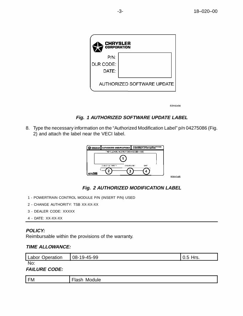
-3- 18–020–00
Fig. 1 AUTHORIZED SOFTWARE UPDATE LABEL
8. Type the necessary information on the “Authorized Modification Label” p/n 04275086 (Fig.2) and attach the label near the VECI label.
Fig. 2 AUTHORIZED MODIFICATION LABEL
1 - POWERTRAIN CONTROL MODULE P/N (INSERT P/N) USED
2 - CHANGE AUTHORITY: TSB XX-XX-XX
3 - DEALER CODE: XXXXX
4 - DATE: XX-XX-XX
POLICY:Reimbursable within the provisions of the warranty.
TIME ALLOWANCE:
Labor OperationNo:
08-19-45-99 0.5 Hrs.
FAILURE CODE:
FM Flash Module


NUMBER: 18–021–00
GROUP: VehiclePerformance
DATE: Oct. 6, 2000
This bulletin is supplied as technical information only and is not an authorization for repair. No part of this publication may be reproduced, stored in a retreival system,or transmitted, in any form or by any means, electronic, mechanical, photocopying, or otherwise, without written permission of DaimlerChrysler Corporation.
SUBJECT:Intermittent VTA, Overhead Temperature Display Slow To Update, Poor A/C PerformanceAfter Start Up
OVERVIEW:This bulletin involves selectively erasing and reprogramming the Powertrain Control Module(PCM) with new software.
MODELS:
1998 - 1999 (LH) Concorde/Intrepid/LHS/300M
NOTE: THIS INFORMATION APPLIES TO VEHICLES THAT HAVE HAD THEIR POW-ERTRAIN CONTROL MODULE (PCM) REPLACED WITH 2000 OR LATER PCM HARD-WARE. HARDWARE IDENTIFICATION CAN BE MADE AS FOLLOWS:
The label located on the PCM includes a serial number (S/N TxxEHyyyzzzwww) that identi-fies the year of the circuit board inside the controller. The 2nd and 3rd positions (xx) indicatethe year.
PCM Model Year Engine Application 2nd/3rd Position
3.2L/3.5L 812000
2.7L 92
PCM’s with numbers less than those listed in the table are not included in the Technical Service Bulletin.
SYMPTOM/CONDITION:Some vehicles may exhibit one or more of the following: Vehicle Theft Alarm (VTA) securitylight intermittently NOT blinking after locking all doors and/or the outside temperature displaywill be slow to update and/or poor A/C performance is experienced after vehicle start up.
DIAGNOSIS:Using the Mopar Diagnostic System (MDS2) and or the Diagnostic Scan Tool (DRB III®) withthe appropriate Diagnostic Procedures, verify all engine/transmission systems are function-ing as designed. If other Diagnostic Trouble Codes (DTC’s) are present, record them on therepair order and repair as necessary before proceeding further with this bulletin. If the con-dition(s) can be duplicated or is described by the customer, perform the Repair Procedure.
NOTE: WHENEVER A POWERTRAIN CONTROL MODULE (PCM) IS REPLACED, THESOFTWARE OF THE REPLACEMENT CONTROLLER MUST BE VERIFIED FOR THE
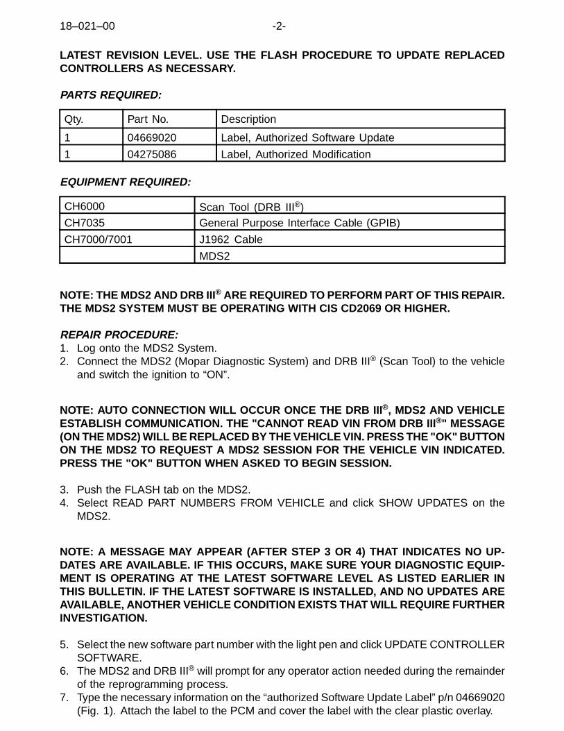
18–021–00 -2-
LATEST REVISION LEVEL. USE THE FLASH PROCEDURE TO UPDATE REPLACEDCONTROLLERS AS NECESSARY.
PARTS REQUIRED:
Qty. Part No. Description
1 04669020 Label, Authorized Software Update
1 04275086 Label, Authorized Modification
EQUIPMENT REQUIRED:
CH6000 Scan Tool (DRB III®)CH7035 General Purpose Interface Cable (GPIB)
CH7000/7001 J1962 Cable
MDS2
NOTE: THE MDS2 AND DRB III ® ARE REQUIRED TO PERFORM PART OF THIS REPAIR.THE MDS2 SYSTEM MUST BE OPERATING WITH CIS CD2069 OR HIGHER.
REPAIR PROCEDURE:1. Log onto the MDS2 System.2. Connect the MDS2 (Mopar Diagnostic System) and DRB III® (Scan Tool) to the vehicle
and switch the ignition to “ON”.
NOTE: AUTO CONNECTION WILL OCCUR ONCE THE DRB III ®, MDS2 AND VEHICLEESTABLISH COMMUNICATION. THE "CANNOT READ VIN FROM DRB III ®" MESSAGE(ON THE MDS2) WILL BE REPLACED BY THE VEHICLE VIN. PRESS THE "OK" BUTTONON THE MDS2 TO REQUEST A MDS2 SESSION FOR THE VEHICLE VIN INDICATED.PRESS THE "OK" BUTTON WHEN ASKED TO BEGIN SESSION.
3. Push the FLASH tab on the MDS2.4. Select READ PART NUMBERS FROM VEHICLE and click SHOW UPDATES on the
MDS2.
NOTE: A MESSAGE MAY APPEAR (AFTER STEP 3 OR 4) THAT INDICATES NO UP-DATES ARE AVAILABLE. IF THIS OCCURS, MAKE SURE YOUR DIAGNOSTIC EQUIP-MENT IS OPERATING AT THE LATEST SOFTWARE LEVEL AS LISTED EARLIER INTHIS BULLETIN. IF THE LATEST SOFTWARE IS INSTALLED, AND NO UPDATES AREAVAILABLE, ANOTHER VEHICLE CONDITION EXISTS THAT WILL REQUIRE FURTHERINVESTIGATION.
5. Select the new software part number with the light pen and click UPDATE CONTROLLERSOFTWARE.
6. The MDS2 and DRB III® will prompt for any operator action needed during the remainderof the reprogramming process.
7. Type the necessary information on the “authorized Software Update Label” p/n 04669020(Fig. 1). Attach the label to the PCM and cover the label with the clear plastic overlay.

-3- 18–021–00
Fig. 1 AUTHORIZED SOFTWARE UPDATE LABEL
8. Type the necessary information on the “Authorized Modification Label” p/n 04275086 (Fig.2) and attach the label near the VECI label.
Fig. 2 AUTHORIZED MODIFICATION LABEL
1 - POWERTRAIN CONTROL MODULE P/N (INSERT P/N) USED
2 - CHANGE AUTHORITY: TSB XX-XX-XX
3 - DEALER CODE: XXXXX
4 - DATE: XX-XX-XX
POLICY:Reimbursable within the provisions of the warranty.
TIME ALLOWANCE:
Labor OperationNo:
08-19-46-91 0.5 Hrs.
FAILURE CODE:
FM Flash Module


NUMBER: 18-022-00
GROUP: VehiclePerformance
DATE: Dec. 01, 2000
This bulletin is supplied as technical information only and is not an authorization for repair. No part of this publication may be reproduced, stored in a retreival system,or transmitted, in any form or by any means, electronic, mechanical, photocopying, or otherwise, without written permission of DaimlerChrysler Corporation.
SUBJECT:2001 M.Y. Engine Spark Knock
OVERVIEW:This bulletin involves selectively erasing and reprogramming the Powertrain ControlModule (PCM) with new software (calibration level 01Cal1ED and 01Cal13)
MODELS:
2001 (BR/BE) Ram Truck
2001 (DN) Durango
NOTE: THIS BULLETIN APPLIES TO VEHICLES EQUIPPED WITH A 3.9L(EHC), A 5.2L (ELF,) OR A 5.9L LIGHT DUTY (EML) GASOLINE ENGINE. THISBULLETIN ALSO APPLIES TO RAM TRUCK VEHICLES BUILT PRIOR TOAUGUST 01, 2000 (MDH 0801XX), AND TO DURANGO R/T VEHICLES BUILTPRIOR TO OCTOBER 27, 2000 (MDH 1027XX). SEE THE TWO TABLES BELOWFOR SPECIFIC APPLICATIONS AND EXCLUSIONS.
VEH ENGINE TRANS EMISSIONS CD REL
BR/BE 3.9L A4 / M5 Fed and Calif 2072
BR/BE 5.2L A4 Fed and Calif 2072
DN R/T 5.9L A4 Fed and Calif 2072
Legend: A4 = 4 speed automatic trans. M5 = 5 speed manual trans.
NOTE: THE FOLLOWING EMISSION PACKAGES ARE NOT APPROVED ANDARE EXCLUDED FROM THIS BULLETIN. THE PCM CALIBRATION OF ANYEXCLUDED VEHICLE IS NOT TO BE REPROGRAMMED FOR A SPARK KNOCKCOMPLAINT. BEFORE ATTEMPTING A REPROGRAMMING SESSION INSPECTTHE TYPE VEHICLE AND ENGINE FOR POSSIBLE EXCLUSION.
VEHICLE TYPE ENG / TRANS / EMISS
BR/BE ALL 5.9L Heavy Duty (EMM)
BR/BE ALL 8.0L (EWA - Sales Code)
18-022-00 -2-
SYMPTOM/CONDITION:Some vehicle engines may exhibit a light-to-moderate spark knock conditionduring acceleration (under load).
DIAGNOSIS PROCEDURES:1. Verify that the following NOTE(S) have been reviewed and completed as necessary.2. Verify that the engine coolant contains a quality antifreeze. The coolant
mixture should consist of 44% to 68% antifreeze.3. If the only condition seen is the light-to-moderate engine spark knock,
then perform the Repair Procedure.
NOTE: WHEN PULLING A HEAVY LOAD OR DRIVING A FULLY LOADED VEHICLEUSE A PREMIUM UNLEADED FUEL TO HELP MINIMIZE SPARK KNOCK.
NOTE: WHENEVER A POWERTRAIN CONTROL MODULE IS REPLACED DUE TOFAILURE, THE SOFTWARE OF THE REPLACEMENT CONTROLLER MUST BEVERIFIED FOR THE LATEST REVISION LEVEL. USE THE FLASH PROCEDURETO UPDATE REPLACED CONTROLLERS AS NECESSARY.
PARTS REQUIRED:
Qty. Part No. Description
1 04669020 Label, Authorized Software Update
1 04275086 Label, Authorized Modification
EQUIPMENT REQUIRED:
CH6000 Scan Tool (DRB III®)
CH7035 General Purpose Interface Bus Cable (GPIB)
CH7000/7001 J1962 Cable
MDS2 (Mopar Diagnostic System)
NOTE: THE MDS2 AND DRB III ® ARE REQUIRED TO PERFORM PART OF THISREPAIR, WHEN USING THE MDS2 AND THE DRB III ®, THE SYSTEM MUST BEOPERATING AT CIS CD 2069 OR HIGHER (SEE TABLE ON PAGE ONE).
REPAIR PROCEDURE:1. Log onto the MDS2 (Mopar Diagnostic System).2. Connect the MDS2 and DRB III® to the vehicle and switch the ignition key to “ON”.
NOTE: AUTO CONNECTION WILL OCCUR ONCE THE DRB III ®, MDS2, AND VEHICLEESTABLISH COMMUNICATION. THE “CANNOT READ VIN FROM DRB III ®” MESSAGE(ON THE MDS2) WILL BE REPLACED BY THE VEHICLE VIN. PRESS THE “OK”BUTTON ON THE MDS2 TO REQUEST A MDS2 SESSION FOR THE VEHICLE VININDICATED. PRESS THE “OK”BUTTON WHEN ASKED TO BEGIN SESSION.
3. Push the FLASH tab on the MDS2.
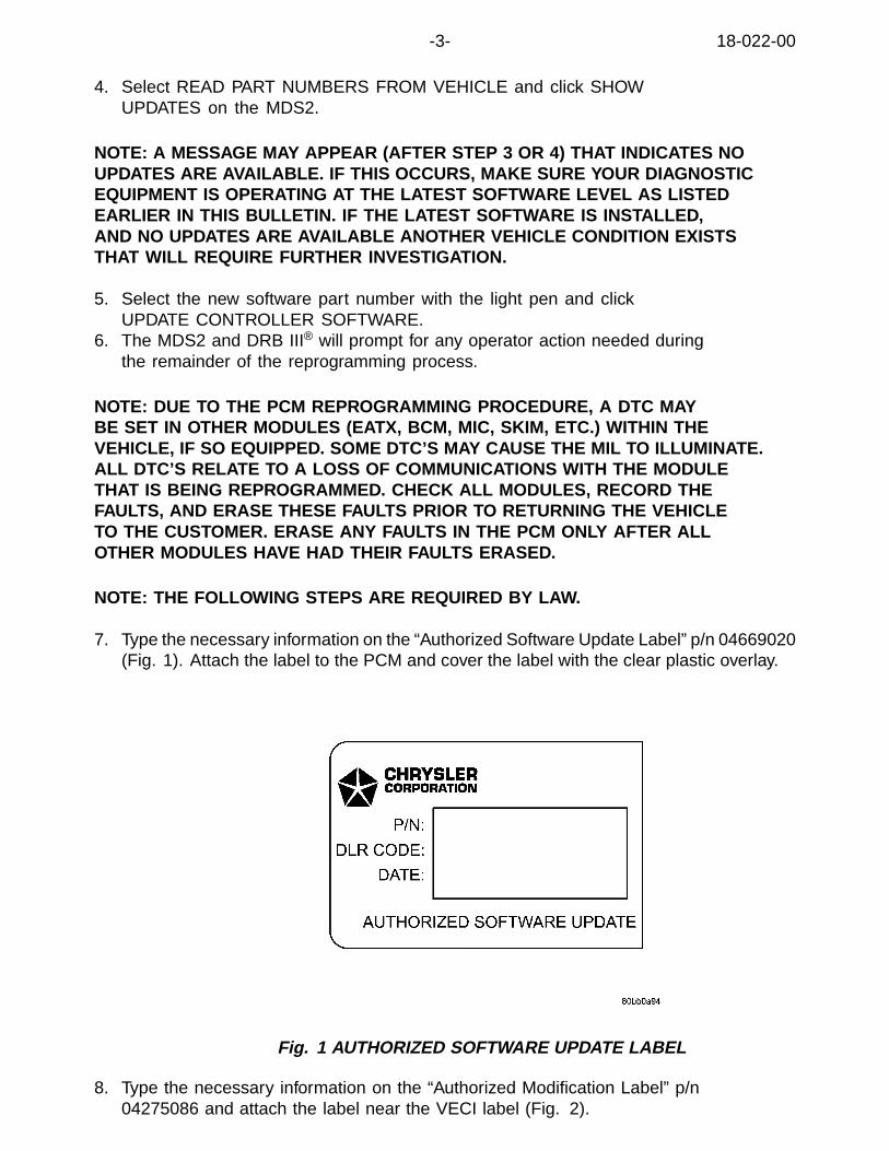
-3- 18-022-00
4. Select READ PART NUMBERS FROM VEHICLE and click SHOWUPDATES on the MDS2.
NOTE: A MESSAGE MAY APPEAR (AFTER STEP 3 OR 4) THAT INDICATES NOUPDATES ARE AVAILABLE. IF THIS OCCURS, MAKE SURE YOUR DIAGNOSTICEQUIPMENT IS OPERATING AT THE LATEST SOFTWARE LEVEL AS LISTEDEARLIER IN THIS BULLETIN. IF THE LATEST SOFTWARE IS INSTALLED,AND NO UPDATES ARE AVAILABLE ANOTHER VEHICLE CONDITION EXISTSTHAT WILL REQUIRE FURTHER INVESTIGATION.
5. Select the new software part number with the light pen and clickUPDATE CONTROLLER SOFTWARE.
6. The MDS2 and DRB III® will prompt for any operator action needed duringthe remainder of the reprogramming process.
NOTE: DUE TO THE PCM REPROGRAMMING PROCEDURE, A DTC MAYBE SET IN OTHER MODULES (EATX, BCM, MIC, SKIM, ETC.) WITHIN THEVEHICLE, IF SO EQUIPPED. SOME DTC’S MAY CAUSE THE MIL TO ILLUMINATE.ALL DTC’S RELATE TO A LOSS OF COMMUNICATIONS WITH THE MODULETHAT IS BEING REPROGRAMMED. CHECK ALL MODULES, RECORD THEFAULTS, AND ERASE THESE FAULTS PRIOR TO RETURNING THE VEHICLETO THE CUSTOMER. ERASE ANY FAULTS IN THE PCM ONLY AFTER ALLOTHER MODULES HAVE HAD THEIR FAULTS ERASED.
NOTE: THE FOLLOWING STEPS ARE REQUIRED BY LAW.
7. Type the necessary information on the “Authorized Software Update Label” p/n 04669020(Fig. 1). Attach the label to the PCM and cover the label with the clear plastic overlay.
Fig. 1 AUTHORIZED SOFTWARE UPDATE LABEL
8. Type the necessary information on the “Authorized Modification Label” p/n04275086 and attach the label near the VECI label (Fig. 2).

18-022-00 -4-
Fig. 2 AUTHORIZED MODIFICATION LABEL
1 - POWERTRAIN CONTROL MODULE P/N (INSERT P/N) USED
2 - CHANGE AUTHORITY: TSB XX-XX-XX
3 - DEALER CODE: XXXXX
4 - DATE: XX-XX-XX
POLICY:Reimbursable within the provisions of the warranty.
TIME ALLOWANCE:
Labor Operation No:
08-19-44-92 Reprogram PCM 0.5 Hrs.
FAILURE CODE: Could be one or more
FM Flash Module

NUMBER: 18-023-00 Rev. A
GROUP: VehiclePerformance
DATE: Dec. 21, 2000
This bulletin is supplied as technical information only and is not an authorization for repair. No part of this publication may be reproduced, stored in a retreival system,or transmitted, in any form or by any means, electronic, mechanical, photocopying, or otherwise, without written permission of DaimlerChrysler Corporation.
THIS BULLETIN SUPERCEDES TECHNICAL SERVICE BULLETIN 18-023-00,DATED DEC. 01, 2000, WHICH SHOULD BE REMOVED FROM YOURFILES. ALL REVISIONS ARE HIGHLIGHTED WITH **ASTERISKS** ANDINCLUDE AN UPDATE TO THE MODELS.
SUBJECT:4.7L Engine Performance Enhancements
OVERVIEW:This bulletin involves selectively erasing and reprogramming the Powertrain ControlModule (PCM) with new software (calibration level 99Cal20 and 00Cal17)
MODELS:
**2000 (AN) Dakota**
**2000 (DN) Durango**
1999 - 2000 (WJ) Grand Cherokee
NOTE: THIS BULLETIN APPLIES TO GRAND CHEROKEE VEHICLESEQUIPPED WITH A 4.7L ENGINE AND WITH FEDERAL EMISSIONS (NAASALES CODE). IT ALSO APPLIES TO ALL DAKOTA AND DURANGOVEHICLES EQUIPPED WITH A 4.7L ENGINE.
SYMPTOM/CONDITION:Some vehicle engines may exhibit several of the following engine performance conditions:1. Part throttle or wide open throttle spark knock.2. Sag or hesitation following a cold engine start.3. Rough idle.4. Idle sag when decelerating to a stop.
DIAGNOSIS PROCEDURES:1. If the customer experiences any of the above conditions, then perform
the Repair Procedure.
PARTS REQUIRED:
Qty. Part No. Description
1 04669020 Label, Authorized Software Update
1 04275086 Label, Authorized Modification

18-023-00 Rev. A -2-
EQUIPMENT REQUIRED:
CH6000 Scan Tool (DRB III®)
CH7035 General Purpose Interface Bus Cable (GPIB)
CH7000/7001 J1962 Cable
MDS2 (Mopar Diagnostic System)
NOTE: THE MDS2 AND DRB III ® ARE REQUIRED TO PERFORM PART OFTHIS REPAIR, WHEN USING THE MDS2 AND THE DRB III ®, THE SYSTEMMUST BE OPERATING AT CIS CD 2073 OR HIGHER.
REPAIR PROCEDURE:1. Log onto the MDS2 (Mopar Diagnostic System).2. Connect the MDS2 and DRB III® to the vehicle and switch the ignition key to “ON”.
NOTE: AUTO CONNECTION WILL OCCUR ONCE THE DRB III ®, MDS2, AND VEHICLEESTABLISH COMMUNICATION. THE “CANNOT READ VIN FROM DRB III ®” MESSAGE(ON THE MDS2) WILL BE REPLACED BY THE VEHICLE VIN. PRESS THE “OK”BUTTON ON THE MDS2 TO REQUEST A MDS2 SESSION FOR THE VEHICLE VININDICATED. PRESS THE “OK”BUTTON WHEN ASKED TO BEGIN SESSION.
3. Push the FLASH tab on the MDS2.4. Select READ PART NUMBERS FROM VEHICLE and click SHOW
UPDATES on the MDS2.
NOTE: A MESSAGE MAY APPEAR (AFTER STEP 3 OR 4) THAT INDICATES NOUPDATES ARE AVAILABLE. IF THIS OCCURS, MAKE SURE YOUR DIAGNOSTICEQUIPMENT IS OPERATING AT THE LATEST SOFTWARE LEVEL AS LISTEDEARLIER IN THIS BULLETIN. IF THE LATEST SOFTWARE IS INSTALLED,AND NO UPDATES ARE AVAILABLE ANOTHER VEHICLE CONDITION EXISTSTHAT WILL REQUIRE FURTHER INVESTIGATION.
5. Select the new software part number with the light pen and clickUPDATE CONTROLLER SOFTWARE.
6. The MDS2 and DRB III® will prompt for any operator action needed duringthe remainder of the reprogramming process.
NOTE: DUE TO THE PCM REPROGRAMMING PROCEDURE, A DTC MAYBE SET IN OTHER MODULES (EATX, BCM, MIC, SKIM, ETC.) WITHIN THEVEHICLE, IF SO EQUIPPED. SOME DTC’S MAY CAUSE THE MIL TO ILLUMINATE.ALL DTC’S RELATE TO A LOSS OF COMMUNICATIONS WITH THE MODULETHAT IS BEING REPROGRAMMED. CHECK ALL MODULES, RECORD THEFAULTS, AND ERASE THESE FAULTS PRIOR TO RETURNING THE VEHICLETO THE CUSTOMER. ERASE ANY FAULTS IN THE PCM ONLY AFTER ALLOTHER MODULES HAVE HAD THEIR FAULTS ERASED.
NOTE: THE FOLLOWING STEPS ARE REQUIRED BY LAW.

-3- 18-023-00 Rev. A
7. Type the necessary information on the “Authorized Software Update Label” p/n 04669020(Fig. 1). Attach the label to the PCM and cover the label with the clear plastic overlay.
Fig. 1 AUTHORIZED SOFTWARE UPDATE LABEL
8. Type the necessary information on the “Authorized Modification Label” p/n04275086 and attach the label near the VECI label (Fig. 2).
Fig. 2 AUTHORIZED MODIFICATION LABEL
1 - POWERTRAIN CONTROL MODULE P/N (INSERT P/N) USED
2 - CHANGE AUTHORITY: TSB XX-XX-XX
3 - DEALER CODE: XXXXX
4 - DATE: XX-XX-XX
POLICY:Reimbursable within the provisions of the warranty.
TIME ALLOWANCE:
Labor Operation No:
08-19-44-96 Reprogram PCM 0.5 Hrs.

18-023-00 Rev. A -4-
FAILURE CODE:
FM Flash Module

NUMBER: 18-024-00
GROUP: VehiclePerformance
DATE: Dec. 21, 2000
This bulletin is supplied as technical information only and is not an authorization for repair. No part of this publication may be reproduced, stored in a retreival system,or transmitted, in any form or by any means, electronic, mechanical, photocopying, or otherwise, without written permission of DaimlerChrysler Corporation.
SUBJECT:Low Engine Power When The Automatic Transmission Is In Overdrive
OVERVIEW:This bulletin involves selectively erasing and reprogramming the Cummins CM551Engine Control Module (ECM) with new software (calibration versions: 56T13,59T6). There is no change to the JTEC PCM software.
MODELS:
2001 (BR/BE) Ram Truck
NOTE: THIS BULLETIN APPLIES TO VEHICLES EQUIPPED WITH A 5.9L-24VDIESEL ENGINE AND AUTOMATIC TRANSMISSION BUILT BETWEEN ENGINESERIAL NUMBERS 56666444 TO 56798357, WITH A DATE OF MANUFACTUREOF DEC. 15, 1999 TO NOV. 15, 2000. THIS INFORMATION IS AVAILABLE ONTHE ENGINE DATA PLATE, WHICH IS LOCATED ON THE LEFT SIDE OF THEENGINE, AFFIXED TO THE SIDE OF THE TIMING GEAR HOUSING.
SYMPTOM/CONDITION:The customer may complain of low engine power and/or poor performance.This engine condition may occur while the automatic transmission is beingoperated in its overdrive gear. This condition may be further aggravated if thecustomer is using the vehicle for towing purposes.The Engine Control Module (ECM) software, on a 2001 Ram Truck equipped with a5.9L-24V diesel engine, is designed to “torque manage” the power output of the engine.This is done to protect the automatic transmission components. The revised softwarecalibration restores the power output and improves the vehicle performance in overdrive.
NOTE: IF TSB 18-015-00 REV A HAS PREVIOUSLY BEEN PERFORMED TO THEVEHICLE IN QUESTION, THEN THE ECM SOFTWARE HAS ALREADY BEENREVISED WITH THE CORRECT CALIBRATION TO ADDRESS THE ABOVECONDITION. THE ECM WILL NOT REQUIRE REPROGRAMMING.
DIAGNOSIS PROCEDURES:Using the Mopar Diagnostic System (MDS2) and or the Diagnostic Scan Tool (DRBIII®), with the appropriate Diagnostic Procedures Manual, verify that all engine andtransmission systems are functioning as designed. If Diagnostic Trouble Codes(DTC’s) are present, record them on the repair order and repair as necessarybefore proceeding further with this bulletin. If no DTC’s are present, and the abovesymptom has been experienced, perform the Repair Procedure.
18-024-00 -2-
PARTS REQUIRED:
Qty. Part No. Description
1 04669020 Label, Authorized Software Update
1 04275086 Label, Authorized Modification
EQUIPMENT REQUIRED:
CH6000 Scan Tool (DRB III®)
CH7035 General Purpose Interface Bus Cable (GPIB)
CH7000/7001 J1962 Cable
MDS2 (Mopar Diagnostic System)
NOTE: THE MDS2 AND DRB III ® ARE REQUIRED TO PERFORM PART OFTHIS REPAIR, WHEN USING THE MDS2 AND THE DRB III ®, THE SYSTEMMUST BE OPERATING AT CIS CD 2073 OR HIGHER.
REPAIR PROCEDURE:1. Log onto the MDS2 (Mopar Diagnostic System).2. Connect the MDS2 and DRB III® to the vehicle and switch the ignition key to “ON”.
NOTE: AUTO CONNECTION WILL OCCUR ONCE THE DRB III ®, MDS2, AND VEHICLEESTABLISH COMMUNICATION. THE “CANNOT READ VIN FROM DRB III ®” MESSAGE(ON THE MDS2) WILL BE REPLACED BY THE VEHICLE VIN. PRESS THE “OK”BUTTON ON THE MDS2 TO REQUEST A MDS2 SESSION FOR THE VEHICLE VININDICATED. PRESS THE “OK”BUTTON WHEN ASKED TO BEGIN SESSION.
3. Push the FLASH tab on the MDS2.4. Select READ PART NUMBERS FROM VEHICLE and click SHOW
UPDATES on the MDS2.
NOTE: A MESSAGE MAY APPEAR (AFTER STEP 3 OR 4) THAT INDICATES NOUPDATES ARE AVAILABLE. IF THIS OCCURS, MAKE SURE YOUR DIAGNOSTICEQUIPMENT IS OPERATING AT THE LATEST SOFTWARE LEVEL AS LISTEDEARLIER IN THIS BULLETIN. IF THE LATEST SOFTWARE IS INSTALLED,AND NO UPDATES ARE AVAILABLE ANOTHER VEHICLE CONDITION EXISTSTHAT WILL REQUIRE FURTHER INVESTIGATION.
5. Select the new software part number with the light pen and clickUPDATE CONTROLLER SOFTWARE.
6. The MDS2 and DRB III® will prompt for any operator action needed duringthe remainder of the reprogramming process.
NOTE: DUE TO THE ECM REPROGRAMMING PROCEDURE, A DTC MAY BESET IN OTHER MODULES (PCM, BCM, MIC, SKIM, ETC.) WITHIN THE VEHICLE,IF SO EQUIPPED. SOME DTC’S MAY CAUSE THE MIL TO ILLUMINATE. ALLDTC’S RELATE TO A LOSS OF COMMUNICATIONS WITH THE MODULETHAT IS BEING REPROGRAMMED. CHECK ALL MODULES, RECORD THE

-3- 18-024-00
FAULTS, AND ERASE THESE FAULTS PRIOR TO RETURNING THE VEHICLETO THE CUSTOMER. ERASE ANY FAULTS IN THE PCM ONLY AFTER ALLOTHER MODULES HAVE HAD THEIR FAULTS ERASED.
NOTE: THE FOLLOWING STEPS ARE REQUIRED BY LAW.
7. Type the necessary information on the “Authorized Software Update Label” p/n04669020 (Fig. 1). Attach the label to the CUMMINS ECM and cover the label withthe clear plastic overlay. Do not attach the label to the JTEC PCM.
Fig. 1 AUTHORIZED MODIFICATION LABEL
1 - POWERTRAIN CONTROL MODULE P/N (INSERT P/N) USED
2 - CHANGE AUTHORITY: TSB XX-XX-XX
3 - DEALER CODE: XXXXX
4 - DATE: XX-XX-XX
8. Type the necessary information on the “Authorized Modification Label” p/n04275086 and attach the label near the VECI label (Fig. 2).
Fig. 2 AUTHORIZED SOFTWARE UPDATE LABEL
POLICY:Reimbursable within the provisions of the warranty.

18-024-00 -4-
TIME ALLOWANCE:
Labor Operation No:
08-19-45-93 Reprogram PCM 0.5 Hrs.
FAILURE CODE:
FM Flash Module
2000 INDEX
GROUP 19STEERING
BULLETIN SUBJECT MODELS TSB NO.
GROUP 19 - STEERING
Steering Gear/Front Suspension Rattle 1998 - 2000 LH,LHS/300M 19-01-00
Ignition Lock Cylinder Service 2000 - PL,JA,JX,XJ,TJ2001 - PT
19-02-00 Rev. A
Loose Steering 1993 - 2000 LH 19-03-00 Rev. B
Squeaking/Creaking Sound In Steering ColumnWhile Turning
1994 - 2000 BR/BE,1997 - 2000 AN,1998 -2000 (R1)
19-04-00
Low Speed Power Steering Moan 2000 - 2001 PL 19-05-00
Steering Gear Honk On Turns 1999 - 2000 WJ 19-06-00
Steering Wander Diagnosis 1998 - 2001 AB 19-07-00
High Pitched Whistle Sound Heard While Driving 2001 - BR/BE 19-08-00
Popping Sensation/Sound In Steering ColumnWhile Turning
2001 - NA,DN,R1 19-09-00


Form TSB-003 Rev. 1.07
NUMBER: 19-01-00
GROUP: Steering
DATE: Jan. 21, 2000
SUBJECT:Steering Gear/Front Suspension Rattle
OVERVIEW:This bulletin involves diagnosing a steering gear rack rattle condition.
MODELS:1998 - 2000 (LH) Concorde/Intrepid/LHS 300M
SYMPTOM/CONDITION:Rattle sound coming from front of vehicle. More noticeable at slow speeds on rough roador over speed bumps. May sound like a front suspension component.
DIAGNOSIS:If rattle can be isolated to the rack housing, inspect for pinholes in the convolutes of thebellows by expanding the convolutes left and right (Figure 1). The pinholes may besurrounded by rusty water stains. If the pinholes cannot be seen, perform RepairProcedure “A”. If the pinholes do exist, and there is a rattle, perform Repair Procedure “B”.
PARTS REQUIRED:1 05018538AA Service Kit Containing Rack Protector and Clamp. (Procedure A)
This bulletin is supplied as technical information only and is not an authorization for repair. No part of this publication may be reproduced, stored in a retrieval system, ortransmitted, in any form or by any means, electronic, mechanical, photocopying, recording, or otherwise, without written permission of DaimlerChrysler Corporation.
FIGURE 1
1 - Pinholes In Bellows
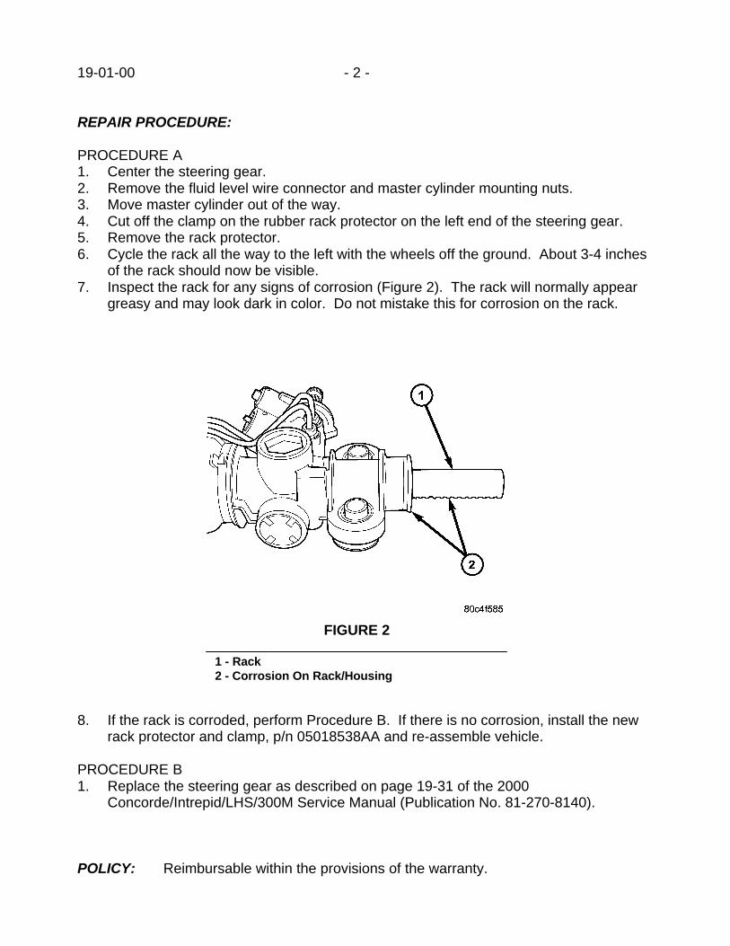
19-01-00 - 2 -
REPAIR PROCEDURE:
PROCEDURE A1. Center the steering gear.2. Remove the fluid level wire connector and master cylinder mounting nuts.3. Move master cylinder out of the way.4. Cut off the clamp on the rubber rack protector on the left end of the steering gear.5. Remove the rack protector.6. Cycle the rack all the way to the left with the wheels off the ground. About 3-4 inches
of the rack should now be visible.7. Inspect the rack for any signs of corrosion (Figure 2). The rack will normally appear
greasy and may look dark in color. Do not mistake this for corrosion on the rack.
8. If the rack is corroded, perform Procedure B. If there is no corrosion, install the newrack protector and clamp, p/n 05018538AA and re-assemble vehicle.
PROCEDURE B1. Replace the steering gear as described on page 19-31 of the 2000
Concorde/Intrepid/LHS/300M Service Manual (Publication No. 81-270-8140).
POLICY: Reimbursable within the provisions of the warranty.
FIGURE 2
1 - Rack2 - Corrosion On Rack/Housing

- 3 - 19-01-00
TIME ALLOWANCE:Labor Operation No: 19-00-01-92 Procedure A ............................................0.3 Hrs.
Replace Rack Protector19-00-01-93 Procedure B ............................................3.2 Hrs.
Replace Steering Gear
FAILURE CODE: P8 - New Part

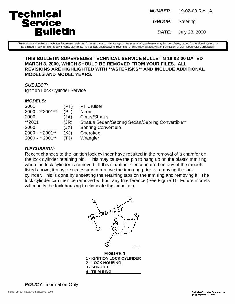
Form TSB-004 Rev. 1.06 February 3, 2000
NUMBER: 19-02-00 Rev. A
GROUP: Steering
DATE: July 28, 2000
THIS BULLETIN SUPERSEDES TECHNICAL SERVICE BULLETIN 19-02-00 DATEDMARCH 3, 2000, WHICH SHOULD BE REMOVED FROM YOUR FILES. ALLREVISIONS ARE HIGHLIGHTED WITH **ASTERISKS** AND INCLUDE ADDITIONALMODELS AND MODEL YEARS.
SUBJECT:Ignition Lock Cylinder Service
MODELS:2001 (PT) PT Cruiser2000 - **2001** (PL) Neon2000 (JA) Cirrus/Stratus**2001 (JR) Stratus Sedan/Sebring Sedan/Sebring Convertible**2000 (JX) Sebring Convertible2000 - **2001** (XJ) Cherokee2000 - **2001** (TJ) Wrangler
DISCUSSION:Recent changes to the ignition lock cylinder have resulted in the removal of a chamfer onthe lock cylinder retaining pin. This may cause the pin to hang up on the plastic trim ringwhen the lock cylinder is removed. If this situation is encountered on any of the modelslisted above, it may be necessary to remove the trim ring prior to removing the lockcylinder. This is done by unseating the retaining tabs on the trim ring and removing it. Thelock cylinder can then be removed without any Interference (See Figure 1). Future modelswill modify the lock housing to eliminate this condition.
POLICY: Information Only
This bulletin is supplied as technical information only and is not an authorization for repair. No part of this publication may be reproduced, stored in a retrieval system, ortransmitted, in any form or by any means, electronic, mechanical, photocopying, recording, or otherwise, without written permission of DaimlerChrysler Corporation.
FIGURE 11 - IGNITION LOCK CYLINDER2 - LOCK HOUSING3 - SHROUD4 - TRIM RING


NUMBER: 19-003-00 Rev. B
GROUP: Steering
DATE: Oct. 6, 2000
This bulletin is supplied as technical information only and is not an authorization for repair. No part of this publication may be reproduced, stored in a retreival system,or transmitted, in any form or by any means, electronic, mechanical, photocopying, or otherwise, without written permission of DaimlerChrysler Corporation.
THIS BULLETIN SUPERCEDES TECHNICAL SERVICE BULLETIN 19-03-00 REV. A,DATED SEPTEMBER 8, 2000, WHICH SHOULD BE REMOVED FROM YOUR FILES.ALL REVISIONS ARE HIGHLIGHTED WITH **ASTERISKS** AND INCLUDE REVISEDLABOR OPERATION NUMBERS.
WARNING: FAILURE TO ACHIEVE A MINIMUM TORQUE OF 100 NM (74 FT. LBS.) MAYRESULT IN THE ATTACHING BOLTS LOOSENING AND FRACTURING. THIS COULDRESULT IN A SUBSEQUENT LOSS OF STEERING CONTROL. BENDING THE RETAIN-ING TABS ALONE WILL NOT PREVENT THIS.
SUBJECT:Loose Steering
OVERVIEW:This bulletin provides service procedures and parts information for the inner tie rod bushings.
MODELS:
1993 - 2000 (LH) Concorde/Intrepid/LHS/New Yorker/Vision/300M
SYMPTOM/CONDITION:Loose feel or clunk in the steering wheel as the wheel is moved from side to side.
DIAGNOSIS:Observe the inner tie rod to steering gear attaching point while moving the steering wheelfrom side to side. If there is movement between the gear and inner tie rod, perform the RepairProcedure. If no movement is evident further diagnosis of the condition will be required.
DISCUSSION:The inner tie rod bushings have previously been serviced with the tie rod assembly. Thisbulletin releases the parts, service procedures, and special tool necessary to service just thebushings. Subsequent service manuals will contain the Repair Procedure.
PARTS REQUIRED:
Qty. Part No. Description
2 05018125AA Bushing, Inner Tie Rod
AR 043318070 Mopar Rubber Silicone Spray
2 06507006AA Bolt, Inner Tie Rod To Steering Gear
2 05017820AA Washer, Inner Tie Rod Attaching Bolt

19-003-00 Rev. B -2-
1 05017715AA Plate, Inner Tie Rod Locking
1 05017714AA Bracket
EQUIPMENT REQUIRED:
8438 Miller Special Tool, Tie Rod Bushing Remover/Installer
REPAIR PROCEDURE:
Fig. 1 REMOVAL TOOL 8438
1 - 8438-3 (SCREW)
2 - INNER TIE ROD
3 - VISE
4 - 8438-1 (RECEIVER)
5 - BUSHING
6 - 8438-4 (REMOVER/INSTALLER)
1. Remove the tie rod assembly as described in Group 19 of the appropriate service manual.
NOTE: WHEN SERVICING THE INNER TIE ROD BUSHINGS, REPLACEMENT OF BUSH-INGS ON BOTH INNER TIE RODS IS RECOMMENDED AS WELL AS ALL ATTACHINGHARDWARE (DISCARD OLD ATTACHING PARTS).
2. Mount Receiver, Special Tool 8438-1, in a vice (Fig. 1).3. Assemble Special Tool 8438 in the following manner to remove the bushing from the inner
tie rod (Figure 1).a. Place the inner tie rod bushing end in the receiver.b. Place Remover/Installer, Special Tool 8438-4, with the small end down on top of the
bushing.
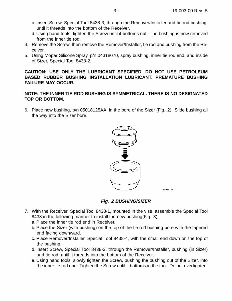
-3- 19-003-00 Rev. B
c. Insert Screw, Special Tool 8438-3, through the Remover/Installer and tie rod bushing,until it threads into the bottom of the Receiver.
d. Using hand tools, tighten the Screw until it bottoms out. The bushing is now removedfrom the inner tie rod.
4. Remove the Screw, then remove the Remover/Installer, tie rod and bushing from the Re-ceiver.
5. Using Mopar Silicone Spray, p/n 04318070, spray bushing, inner tie rod end, and insideof Sizer, Special Tool 8438-2.
CAUTION: USE ONLY THE LUBRICANT SPECIFIED, DO NOT USE PETROLEUMBASED RUBBER BUSHING INSTALLATION LUBRICANT. PREMATURE BUSHINGFAILURE MAY OCCUR.
NOTE: THE INNER TIE ROD BUSHING IS SYMMETRICAL. THERE IS NO DESIGNATEDTOP OR BOTTOM.
6. Place new bushing, p/n 05018125AA, in the bore of the Sizer (Fig. 2). Slide bushing allthe way into the Sizer bore.
Fig. 2 BUSHING/SIZER
7. With the Receiver, Special Tool 8438-1, mounted in the vise, assemble the Special Tool8438 in the following manner to install the new bushing(Fig. 3).a. Place the inner tie rod end in Receiver.b. Place the Sizer (with bushing) on the top of the tie rod bushing bore with the tapered
end facing downward.c. Place Remover/Installer, Special Tool 8438-4, with the small end down on the top of
the bushing.d. Insert Screw, Special Tool 8438-3, through the Remover/Installer, bushing (in Sizer)
and tie rod, until it threads into the bottom of the Receiver.e. Using hand tools, slowly tighten the Screw, pushing the bushing out of the Sizer, into
the inner tie rod end. Tighten the Screw until it bottoms in the tool. Do not overtighten.
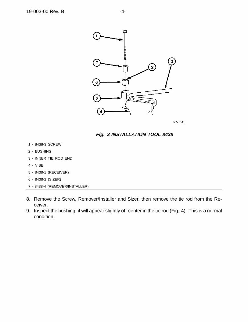
19-003-00 Rev. B -4-
Fig. 3 INSTALLATION TOOL 8438
1 - 8438-3 SCREW
2 - BUSHING
3 - INNER TIE ROD END
4 - VISE
5 - 8438-1 (RECEIVER)
6 - 8438-2 (SIZER)
7 - 8438-4 (REMOVER/INSTALLER)
8. Remove the Screw, Remover/Installer and Sizer, then remove the tie rod from the Re-ceiver.
9. Inspect the bushing, it will appear slightly off-center in the tie rod (Fig. 4). This is a normalcondition.
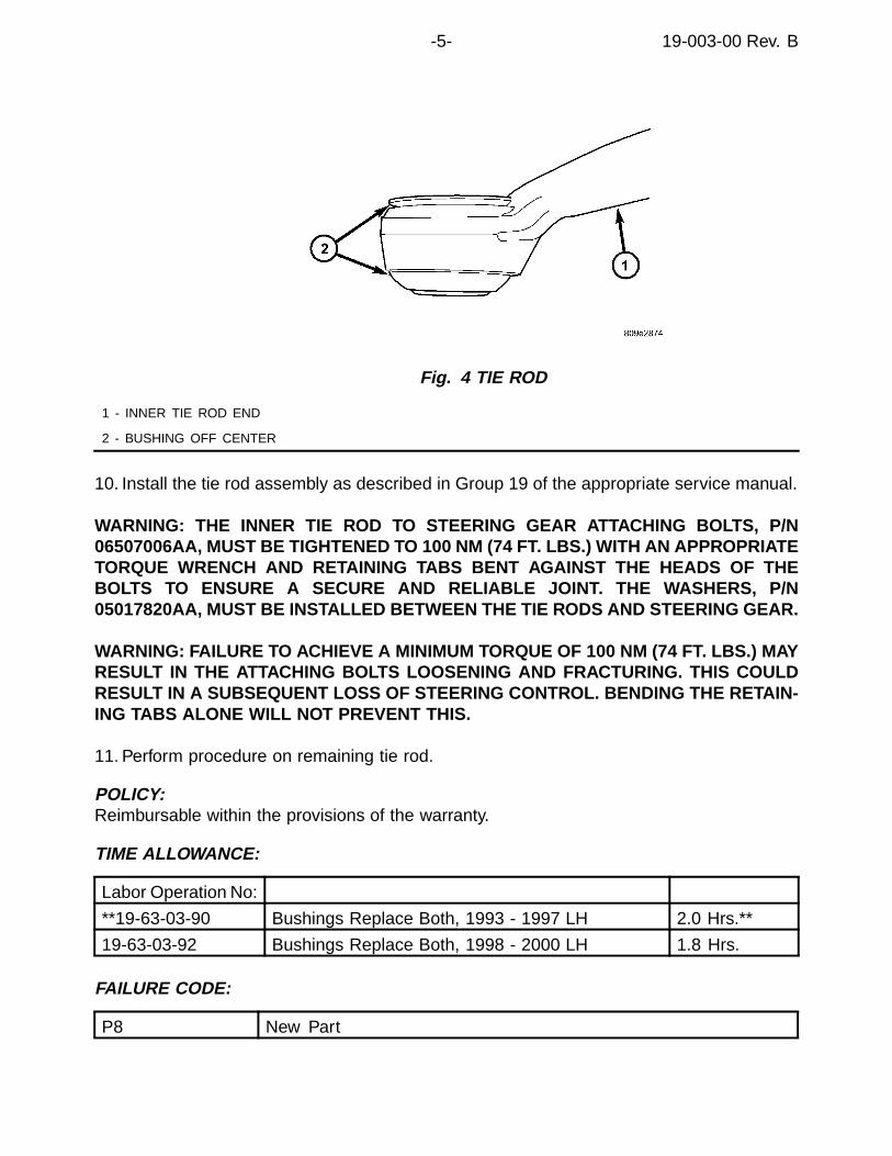
-5- 19-003-00 Rev. B
Fig. 4 TIE ROD
1 - INNER TIE ROD END
2 - BUSHING OFF CENTER
10. Install the tie rod assembly as described in Group 19 of the appropriate service manual.
WARNING: THE INNER TIE ROD TO STEERING GEAR ATTACHING BOLTS, P/N06507006AA, MUST BE TIGHTENED TO 100 NM (74 FT. LBS.) WITH AN APPROPRIATETORQUE WRENCH AND RETAINING TABS BENT AGAINST THE HEADS OF THEBOLTS TO ENSURE A SECURE AND RELIABLE JOINT. THE WASHERS, P/N05017820AA, MUST BE INSTALLED BETWEEN THE TIE RODS AND STEERING GEAR.
WARNING: FAILURE TO ACHIEVE A MINIMUM TORQUE OF 100 NM (74 FT. LBS.) MAYRESULT IN THE ATTACHING BOLTS LOOSENING AND FRACTURING. THIS COULDRESULT IN A SUBSEQUENT LOSS OF STEERING CONTROL. BENDING THE RETAIN-ING TABS ALONE WILL NOT PREVENT THIS.
11. Perform procedure on remaining tie rod.
POLICY:Reimbursable within the provisions of the warranty.
TIME ALLOWANCE:
Labor Operation No:
**19-63-03-90 Bushings Replace Both, 1993 - 1997 LH 2.0 Hrs.**
19-63-03-92 Bushings Replace Both, 1998 - 2000 LH 1.8 Hrs.
FAILURE CODE:
P8 New Part

Form TSB-003 Rev. 1.08 February 3, 2000
NUMBER: 19-04-00
GROUP: Steering
DATE: June 9, 2000
SUBJECT:Squeaking/Creaking Sound In Steering Column While Turning
OVERVIEW:This bulletin involves installing new lock housing attaching screws.
MODELS:1997 - 2000 (AN) Dakota1994 - 2000 (BR/BE) Ram Truck1998 - 2000 (R1) Dakota (International Markets)
NOTE: THIS BULLETIN APPLIES TO VEHICLES EQUIPPED WITH NON-TILTSTEERING COLUMNS.
SYMPTOM/CONDITION:A squeaking/creaking sound may be heard coming from the area of the steering wheelwhile turning. The sound is associated with rotation of the steering wheel or may be heardwhile going over bumps in the road.
DIAGNOSIS:1. Start the engine and center the steering wheel.2. Rotate the steering wheel to the extreme right and then to the extreme left while
monitoring for the squeaking/creaking sound.3. If a squeaking/creaking sound can be heard coming from the area of the steering
wheel, perform the Repair Procedure.
PARTS REQUIRED:5 06506514AA Screw, Non-Tilt Lock Housing
REPAIR PROCEDURE:
1. Remove the three screws that secure the lower edge of the steering column openingcover to the lower instrument panel reinforcement.
2. Using a trim stick or another suitable wide-bladed tool, gently pry the upper edge ofthe steering column opening cover. Pry just below the cluster bezel on each side ofthe steering column away from the instrument panel far enough to disengage thesnap clip retainers from the receptacles in the instrument panel.
3. Remove the steering column opening cover from the instrument panel.4. Loosen the steering column mounting nuts.5. Remove the upper and lower shrouds and covers (4 pieces)(Figure 1).
This bulletin is supplied as technical information only and is not an authorization for repair. No part of this publication may be reproduced, stored in a retrieval system, ortransmitted, in any form or by any means, electronic, mechanical, photocopying, recording, or otherwise, without written permission of DaimlerChrysler Corporation.
THIS REPAIR IS COMPATIBLE WITH DAIMLERCHRYSLER'S MOBILE SERVICE PROGRAM ANDDOES NOT REQUIRE HOISTS OR OTHER FULL SERVICE FACILITY SPECIAL EQUIPMENT.

19-04-00 -2-
6. Disconnect the wiper switch wiring harness connector.7. Remove screw A and replace with new screw, p/n 06506514AA, and tighten to 9 N•m
(85 in. lbs.). See Figure 2 for screw identification.
CAUTION: REMOVE ONLY ONE SCREW AT A TIME.
8. Repeat step 7 for screws B, C, D, and E respectively.9. Connect the wiper switch wiring harness connector.10. Install the upper and lower steering column shrouds to steering column. Tighten
screws to 2 N•m (17 in. lbs.).
11 - UPPER SHROUD2 - LOWER SHROUD3 - PANEL BRACKET
FIGURE 21 - JACKET2 - LOCK HOUSING

Form TSB-003 Rev. 1.07
NUMBER: 19-05-00
GROUP: Steering
DATE: July 14, 2000
SUBJECT:Low Speed Power Steering Moan
OVERVIEW:This bulletin involves the replacement of the power steering reservoir cap. The new powersteering reservoir cap has an internal pressure relief valve and a revised dip-stick.
MODELS:2000 - 2001 (PL) Neon
NOTE: THIS BULLETIN APPLIES TO VEHICLES BUILT PRIOR TO MAY 24, 2000(MDH 0524XX).
SYMPTOM/CONDITION:A moan type sound may be heard during low speed steering wheel inputs at low engineRPM (low speed turns or parking lot maneuvers).
DIAGNOSIS:Drive the vehicle slowly through the parking lot and make slow speed turns, if the powersteering moan is heard, perform the Repair Procedure.
PARTS REQUIRED:1 05066063AA Cap, Power Steering Reservoir1 05010304AA Power Steering Fluid (MS-9933)
REPAIR PROCEDURE:
WARNING: THE POWER STEERING CAP SHOULD ONLY BE REMOVED WITH THEENGINE OFF TO PREVENT PERSONAL INJURY FROM MOVING PARTS.
1. Before opening the power steering system, wipe the reservoir filler cap free of dirtand debris.
2. Remove the cap and discard.3. Install the new cap and use the new dip-stick to check the fluid level. Check the
fluid when it is at normal ambient temperature, approximately 21°C to 27°C (70°F to80°F), the dip stick level should be right at the FULL mark. Correct the fluid level asneeded, do not overfill the power steering system.
This bulletin is supplied as technical information only and is not an authorization for repair. No part of this publication may be reproduced, stored in a retrieval system, ortransmitted, in any form or by any means, electronic, mechanical, photocopying, recording, or otherwise, without written permission of DaimlerChrysler Corporation.
THIS REPAIR IS COMPATIBLE WITH DAIMLERCHRYSLER'S MOBILE SERVICE PROGRAM ANDDOES NOT REQUIRE HOISTS OR OTHER FULL SERVICE FACILITY SPECIAL EQUIPMENT.

19-05-00 -2-
POLICY: Reimbursable within the provisions of the warranty.
TIME ALLOWANCE:Labor Operation No: 19-70-56-90 ...............................................................0.2 Hrs.
FAILURE CODE: P8 - New Part
Form TSB-003 Rev. 1.07
NUMBER: 19-06-00
GROUP: Steering
DATE: Sept. 15, 2000
SUBJECT:Steering Gear Honk On Turns
OVERVIEW:This bulletin involves installing a revised steering gear.
MODELS:1999 - 2000 (WJ) Grand Cherokee (Including US and European built vehicles)
SYMPTOM/CONDITION:A honking sound may be heard when making slow speed sharp turn such as turning into adriveway. The sound will normally happen when making right turns with left hand drivevehicle and when making left turns with right hand drive vehicles.
DIAGNOSIS:If the noise is present, perform the Repair Procedure.
PARTS REQUIRED:
52088272AD Steering Gear - US Built Vehicles52088273AC Steering Gear - European Built Left Hand Drive Vehicles52088471AC Steering Gear - European Built Right Hand Drive Vehicles
REPAIR PROCEDURE:1. Using the procedures outlined in the appropriate Grand Cherokee Service Manual,
remove the steering gear and replace it with the part listed above.
POLICY: Reimbursable within the provisions of the warranty.
TIME ALLOWANCE:Labor Operation No:
Steering Gear Assy. - Replace - Left Hand Drive19-00-01-95 ................................................................1.1 Hrs.
Steering Gear Assy. - Replace - Right Hand Drive19-00-01-96 ................................................................1.4 Hrs.
Skid Plate Equipped19-00-01-60 ................................................................0.2 Hrs.
FAILURE CODE: P8 - New Part
This bulletin is supplied as technical information only and is not an authorization for repair. No part of this publication may be reproduced, stored in a retrieval system, ortransmitted, in any form or by any means, electronic, mechanical, photocopying, recording, or otherwise, without written permission of DaimlerChrysler Corporation.

Form TSB-003 Rev. 1.08 February 3, 2000
NUMBER: 19-07-00
GROUP: Steering
DATE: Sept. 22, 2000
SUBJECT:Steering Wander Diagnosis
OVERVIEW:This bulletin provides a diagnostic procedure for steering wander.
MODELS:1998 - 2001 (AB) Ram Van/Wagon
SYMPTOM/CONDITION:Steering Wander Diagnosis is the diagnosis of a condition where slight steering correctionsare necessary to be able to keep the vehicle moving in a straight line.
Steering wander can be created by a number of different conditions including but notlimited to the following:
• Non-factory installed options.• Tires or wheels of different size.• Aftermarket wheels.• Tires that have a belt that has shifted.• Incorrect tire pressure.• A vehicle that is carrying extra added weight (e.g. tool boxes).• Steering and/or suspension components that are worn or damaged.• Wheel bearings that are loose, worn, or damaged.• A vehicle that is not within alignment specifications.
NOTE: UNDER CERTAIN ROAD CONDITIONS (E.G. HIGH ROAD CROWN,GROOVED ROADS, CROSSWIND, ETC.), MAY CONTRIBUTE TOSTEERING WANDER.
The following Steering Wander Diagnosis was developed to ensure that the vehicle and itssteering system components are functioning as designed and are not the root cause ofsteering wander.
DIAGNOSIS:1. Verify that the vehicle is not equipped with non-factory installed options or equipment
that may cause the vehicle to wander such as heavy toolboxes or hardware that maycause the vehicle to exceed the front or rear Gross Axle Weight Rating (GAWR).
2. Inspect the condition and size of all tire and wheel assemblies. Tires that are worn ordamaged and/or wheels that are of a different size and/or offset than recommendedmay cause the vehicle to wander and should be replaced before continuing with thediagnosis.
This bulletin is supplied as technical information only and is not an authorization for repair. No part of this publication may be reproduced, stored in a retrieval system, ortransmitted, in any form or by any means, electronic, mechanical, photocopying, recording, or otherwise, without written permission of DaimlerChrysler Corporation.

19-07-00 -2-
3. Inflate all tires to the pressure specified in the Tire Inflation Pressure sheet (located inthe glove box).
NOTE: TIRE PRESSURES ARE NORMALLY SET TO THE LIGHT LOADSPECIFICATION WHEN PERFORMING STEERING WANDER DIAGNOSISBUT, ONLY IF THE VEHICLE IS AT CURB OR LIGHT LOAD CONDITIONS.
4. Validate the customer’s concern by test driving the vehicle on a smooth highway, freeof road crown, ruts, speed bumps, or potholes. Drive the vehicle at speeds between80 - 113 km/h (50 - 70 mph), preferably without cross wind conditions. If crosswindconditions are prevalent, drive the vehicle in both directions relative to the crosswind.Proceed to the next step if the vehicle exhibits a steering wander condition.
NOTE: VEHICLES THAT DO NOT EXHIBIT A STEERING WANDER CONDITIONDURING THE ROAD TEST MAY HAVE HAD THE CONDITION CORRECTEDWITH STEPS 1-3 OR THE CONDITION MAY HAVE BEEN CAUSED BY ROADCONDITIONS (E.G. HIGH ROAD CROWN, GROOVED ROADS, ETC.).
5. Raise the vehicle on an appropriate lift.6. Secure a dial indicator to the lower control arm. Position the dial indicator so that the
tip of the indicator contacts the inside face of the rotor (Figure 1).
FIGURE 11 - DISC BRAKE ROTOR2 - DIAL INDICATOR

-3- 19-07-00
7. Place your hands at the top and bottom of the tire/wheel assembly and push thetire/wheel assembly inboard (Figure 2). Zero the dial indicator. With your hands atthe top and bottom of the tire/wheel assembly, pull the tire/wheel assembly outboard(Figure 3). Record the dial indicator reading. Perform this procedure on both frontwheel bearings and proceed to the next step if the wheel bearing endplay exceeds0.025 - 0.076 mm (0.001 - 0.003 in.). Proceed to Step 9 if wheel-bearing endplay onboth front wheel bearings are within specifications.
NOTE: WHEEL BEARING INSPECTION AND ADJUSTMENT IS ONLY REQUIREDON WHEEL BEARINGS EXCEEDING 0.025 - 0.076 MM (0.001 - 0.003 IN.)ENDPLAY.
8. Remove the wheel bearing protective end cap, cotter pin, nut lock, nut, and washerfrom the spindle. Inspect the wheel bearings. If it is determined that wheel bearingreplacement is necessary, refer to the appropriate Ram Van/Wagon Service Manual,Group 02, Wheel Bearings, for removal and installation information. Reinstall thewheel bearings, washer, and adjustment nut if the wheel bearings pass theinspection.
9. Using a torque wrench, tighten the wheel bearing adjustment nut to 54 N•m (40 ft.lbs.) while rotating the tire/wheel assembly. Stop the wheel from rotating and loosenthe nut. Using the procedure identified in Steps 6 and 7 to measure endplay, adjustthe front wheel bearing endplay until 0.025 - 0.076 mm (0.001 - 0.003 in.) endplay hasbeen achieved. Install the nut lock and a new cotter pin.
FIGURE 2 FIGURE 3
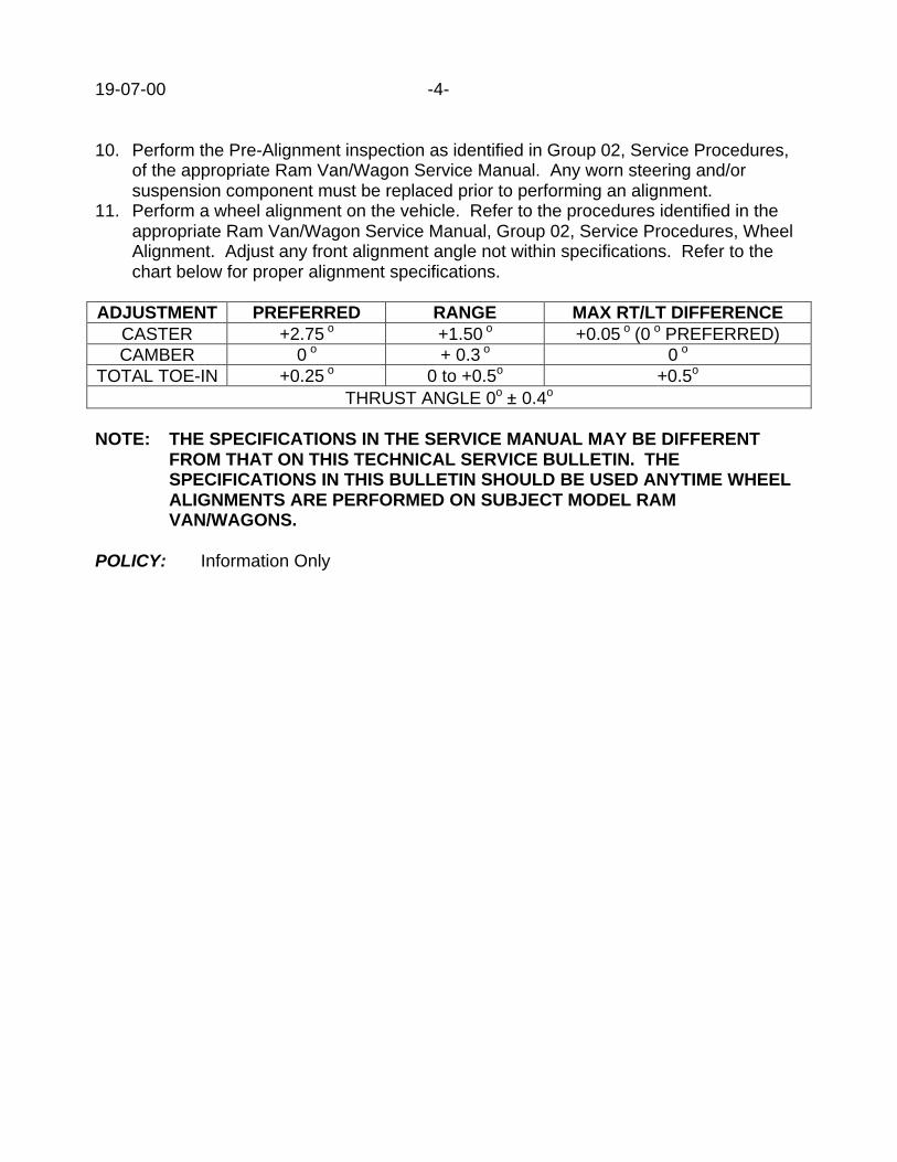
19-07-00 -4-
10. Perform the Pre-Alignment inspection as identified in Group 02, Service Procedures,of the appropriate Ram Van/Wagon Service Manual. Any worn steering and/orsuspension component must be replaced prior to performing an alignment.
11. Perform a wheel alignment on the vehicle. Refer to the procedures identified in theappropriate Ram Van/Wagon Service Manual, Group 02, Service Procedures, WheelAlignment. Adjust any front alignment angle not within specifications. Refer to thechart below for proper alignment specifications.
ADJUSTMENT PREFERRED RANGE MAX RT/LT DIFFERENCECASTER +2.75 o +1.50 o +0.05 o (0 o PREFERRED)CAMBER 0 o + 0.3 o 0 o
TOTAL TOE-IN +0.25 o 0 to +0.5o +0.5o
THRUST ANGLE 0o ±± 0.4o
NOTE: THE SPECIFICATIONS IN THE SERVICE MANUAL MAY BE DIFFERENTFROM THAT ON THIS TECHNICAL SERVICE BULLETIN. THESPECIFICATIONS IN THIS BULLETIN SHOULD BE USED ANYTIME WHEELALIGNMENTS ARE PERFORMED ON SUBJECT MODEL RAMVAN/WAGONS.
POLICY: Information Only
NUMBER: 19-008-00
GROUP: Steering
DATE: Oct. 27, 2000
This bulletin is supplied as technical information only and is not an authorization for repair. No part of this publication may be reproduced, stored in a retreival system,or transmitted, in any form or by any means, electronic, mechanical, photocopying, or otherwise, without written permission of DaimlerChrysler Corporation.
SUBJECT:High Pitched Whistle Sound Heard While Driving
MODELS:
2001 (BR/BE) Ram Trucks
NOTE: THIS BULLETIN APPLIES TO 4X4 SPORT MODELS EQUIPPED WITH THE OFF-ROAD PACKAGE.
DISCUSSION:If a high pitch whistle is heard coming from the front of the vehicle while the vehicle is movingbetween 48 - 97 km/h (30 - 60 mph), inspect the position of the tie rod adjusting sleeve slot.If the slot is facing forward, the slot could catch air passing by it which could cause the whis-tle. To verify if the tie rod adjusting sleeve slot is causing the whistle, wrap tape around thesleeve so that the slot is completely covered (including the ends) and driving the vehicle inthe suspect range. If the high pitch whistle sound is still heard, further diagnosis is required.If the sound has been corrected, position the tie rod adjusting sleeve so that the slot facesany direction except forward.
NOTE: WHEN ADJUSTING THE FRONT TOE OF THE VEHICLE, MAKE SURE THAT THETIE ROD ADJUSTING SLEEVE IS SECURED IN A POSITION SO THAT THE SLOT IS INANY DIRECTION EXCEPT FORWARD.
POLICY:Information Only


NUMBER: 19-009-00
GROUP: Steering
DATE: Dec. 15, 2000
This bulletin is supplied as technical information only and is not an authorization for repair. No part of this publication may be reproduced, stored in a retreival system,or transmitted, in any form or by any means, electronic, mechanical, photocopying, or otherwise, without written permission of DaimlerChrysler Corporation.
SUBJECT:Popping Sensation/Sound In Steering Column While Turning
OVERVIEW:This bulletin involves repositioning the steering column on the steeringcolumn mounting brackets.
MODELS:
2001 (AN) Dakota
2001 (DN) Durango
2001 (R1) Dakota (International Markets)
SYMPTOM/CONDITION:A popping sensation/sound can be felt and/or heard in the steering columnduring sharp turns (parking lot maneuvers).
DIAGNOSIS/REPAIR PROCEDURES:Start the engine. Rotate the steering wheel to the extreme right and then to the extreme leftwhile monitoring for a popping sound or sensation. If a popping sound or sensation can beheard and/or felt in the steering column while turning, perform the Repair Procedure.
REPAIR PROCEDURE:
THIS REPAIR IS COMPATIBLE WITH DAIMLERCHRYSLER’S MOBILESERVICE PROGRAM AND DOES NOT REQUIRE HOISTS OR OTHERFULL SERVICE FACILITY SPECIAL EQUIPMENT.
1. Start the engine.2. Rotate the steering wheel so that the steering wheel is in an upside down position
then remove the ignition key to lock the steering wheel in this position.3. Remove the three screws that secure the lower edge of the steering column
opening cover to the lower instrument panel reinforcement.4. Using a trim stick or another suitable wide-bladed tool, gently pry the upper edge of
the steering column opening cover. Pry just below the cluster bezel on each sideof the steering column away from the instrument panel far enough to disengagethe snap clip retainers from the receptacles in the instrument panel.
5. Remove the steering column opening cover from the instrument panel.6. Loosen the steering column attaching nuts.7. Bounce the steering wheel lightly in a vertical motion to normalize the alignment.8. Without influencing the new location of the steering column, tighten the
rear driver side nut to 25 N·m (225 in. lbs.).

19-009-00 -2-
9. Next, tighten the front passenger side nut to 25 N·m (225 in. lbs.).10. Then, tighten the front driver side nut to 25 N·m (225 in. lbs.).11. Tighten the rear passenger side nut to 25 N·m (225 in. lbs.).12. Position the steering column opening cover to the instrument panel.13. Align the snap clip retainers on the steering column opening cover with
the receptacles in the instrument panel.14. Press firmly on the steering column opening cover over the snap clip locations
until each of the snap clips is fully engaged in its receptacle.15. Install and tighten the three screws that secure the lower edge of the
steering column opening cover to the lower instrument panel reinforcement.Tighten the screws to 2.2 N·m (20 in. lbs.).
16. Start the engine then, rotate the steering wheel back to its normal position.
POLICY:Reimbursable within the provisions of the warranty.
TIME ALLOWANCE:
Labor Operation No: 19-20-83-98 0.2 Hrs.
FAILURE CODE:
XX Service Adjustment
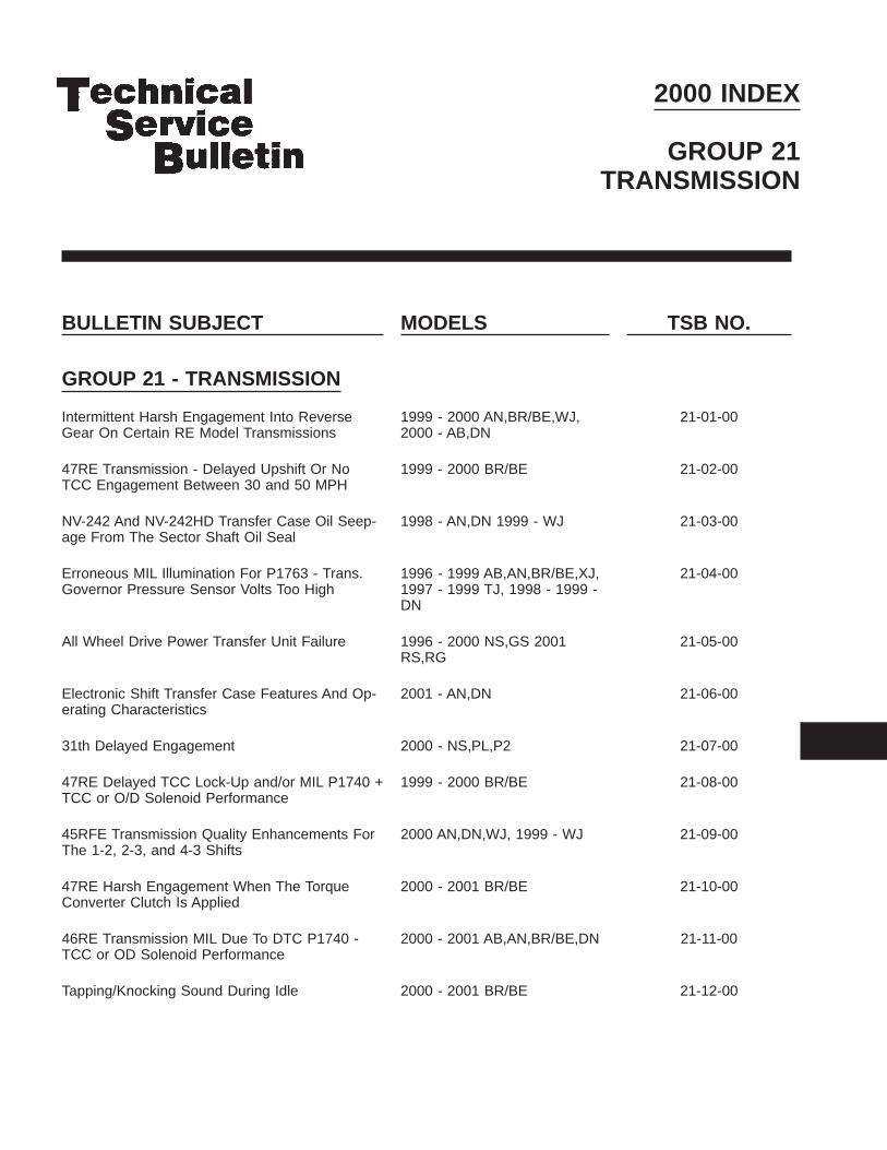
2000 INDEX
GROUP 21TRANSMISSION
BULLETIN SUBJECT MODELS TSB NO.
GROUP 21 - TRANSMISSION
Intermittent Harsh Engagement Into ReverseGear On Certain RE Model Transmissions
1999 - 2000 AN,BR/BE,WJ,2000 - AB,DN
21-01-00
47RE Transmission - Delayed Upshift Or NoTCC Engagement Between 30 and 50 MPH
1999 - 2000 BR/BE 21-02-00
NV-242 And NV-242HD Transfer Case Oil Seep-age From The Sector Shaft Oil Seal
1998 - AN,DN 1999 - WJ 21-03-00
Erroneous MIL Illumination For P1763 - Trans.Governor Pressure Sensor Volts Too High
1996 - 1999 AB,AN,BR/BE,XJ,1997 - 1999 TJ, 1998 - 1999 -DN
21-04-00
All Wheel Drive Power Transfer Unit Failure 1996 - 2000 NS,GS 2001RS,RG
21-05-00
Electronic Shift Transfer Case Features And Op-erating Characteristics
2001 - AN,DN 21-06-00
31th Delayed Engagement 2000 - NS,PL,P2 21-07-00
47RE Delayed TCC Lock-Up and/or MIL P1740 +TCC or O/D Solenoid Performance
1999 - 2000 BR/BE 21-08-00
45RFE Transmission Quality Enhancements ForThe 1-2, 2-3, and 4-3 Shifts
2000 AN,DN,WJ, 1999 - WJ 21-09-00
47RE Harsh Engagement When The TorqueConverter Clutch Is Applied
2000 - 2001 BR/BE 21-10-00
46RE Transmission MIL Due To DTC P1740 -TCC or OD Solenoid Performance
2000 - 2001 AB,AN,BR/BE,DN 21-11-00
Tapping/Knocking Sound During Idle 2000 - 2001 BR/BE 21-12-00


Form TSB-003 Rev. 1.06
NUMBER: 21-01-00
GROUP: Transmission
DATE: Feb. 4, 2000
SUBJECT:Intermittent Harsh Engagement Into Reverse Gear On Certain RE Model Transmissions
OVERVIEW:This bulletin involves the replacement of the transmission valve body upper housingseparator plate and a valve body check ball. In addition, for 2000 M.Y. vehicles equippedwith a 46RE transmission this bulletin involves selectively erasing and reprogramming theJTEC Powertrain Control Module (PCM) with new software (calibration change00Cal13/13A).
MODELS:2000 (AB) Ram Van1999 – 2000 (AN) Dakota1999 – 2000 (BR/BE) Ram Truck2000 (DN) Durango1999 – 2000 (WJ) Grand Cherokee
NOTE: THIS INFORMATION APPLIES TO 1999 AND 2000 MODEL YEAR VEHICLESEQUIPPED WITH EITHER A 42RE AUTOMATIC TRANSMISSION BUILTBEFORE SEPTEMBER 1, 1999 (MDH 0901XX) OR 2000 MODEL YEARVEHICLES EQUIPPED WITH A 46RE AUTOMATIC TRANSMISSION BUILTBEFORE DECEMBER 1, 1999 (MDH 1201XX).
SYMPTOM/CONDITION:The customer may experience a harsh engagement into gear when reverse is selected.This condition may be intermittent, and may occur more frequently as the transmissionfluid warms to normal operating temperatures.
DIAGNOSIS:1. Verify that the transmission fluid level is correct.2. Verify that the valve body throttle valve and transmission shift linkage is adjusted
properly.
Using the Mopar Diagnostic System (MDS2) and or the Diagnostic Scan Tool (DRB III7)with the appropriate Diagnostic Procedures Manual, verify all engine/transmission systemsare functioning as designed. If Diagnostic Trouble Codes (DTC’s) are present, recordthem on the repair order and repair as necessary before proceeding further with thisbulletin. If no DTC’s are present, and the above symptoms have been experienced,perform the Repair Procedure.
NOTE: WHENEVER A POWERTRAIN CONTROL MODULE (PCM) IS REPLACEDDUE TO FAILURE, THE SOFTWARE OF THE REPLACEMENT CONTROLLERMUST BE VERIFIED FOR THE LATEST REVISION LEVEL. USE THE FLASHPROCEDURE TO UPDATE REPLACED CONTROLLERS AS NECESSARY.
This bulletin is supplied as technical information only and is not an authorization for repair. No part of this publication may be reproduced, stored in a retrieval system, ortransmitted, in any form or by any means, electronic, mechanical, photocopying, recording, or otherwise, without written permission of DaimlerChrysler Corporation.
21-01-00 -2-
EQUIPMENT REQUIRED:1 CH6000 Scan Tool (DRB III7)1 CH7035 General Purpose Interface Bus Cable (GPIB)1 CH7000/7001 J1962 Cable1 MDS2
NOTE: THE MDS2 AND DRB III77 ARE REQUIRED TO PERFORM PART OF THISREPAIR. WHEN USING THE MDS2 AND THE DRB III77, THE SYSTEM MUSTBE OPERATING AT CIS CD 2051 OR HIGHER.
PARTS REQUIRED:1 52118261 Ball, Rear Servo Check (“Torlon” – plastic for 42RE and 46RE)1 52118272 Plate, Valve Body Separator (42RE trans.)1 04295875 Gasket, Transmission Pan (42RE trans.)1 04617196AB Plate, Valve Body Separator (46RE trans.)1 05012978AA Gasket, Transmission Pan (46RE trans.)10 05010124AA Fluid, Transmission ATF +3
1(AR) 04669020 Label, Authorized Software Update (if a 46RE trans.)1(AR) 04275086 Label, Authorized Modification (if a 46RE trans.)
REPAIR PROCEDURE:
For both the 1999 and 2000 M.Y. 42RE and 46RE Transmission:1. Refer to the appropriate year Service Manual, Section 21 – Transmission and
Transfer Case for removal and installation instructions of the transmission valve body,check ball, upper housing separator plate, and pan gasket.
2. Replace the original steel rear servo check ball with the plastic “Torlon” check ball(p/n 52118261).
3. Clean the new separator plate to remove any dirt or rust inhibitor prior to installation.4. Install the new transmission valve body upper housing separator plate (p/n 52118272
or p/n 04617196AB).5. Reassemble the transmission.6. Install a new transmission pan gasket (p/n 04295875 or p/n 05012978AA).7. Lower vehicle and install transmission fluid (p/n 05010124AA).8. Verify fluid level after warming up the transmission and cycling the shift lever several
times.9. Verify, and if required, adjust the transmission shift linkage and the transmission
throttle valve cable per the appropriate Service Manual procedures.
For the 2000 M.Y. 46RE Transmission Only:1. Log onto the MDS2 system.2. Connect the MDS2 (Mopar Diagnostic System) and DRB III7 (Scan Tool) to the vehicle
and switch the ignition key to “ON”.3. Use the arrow keys and select #2 CONNECT TO MDS2 on the DRB III7 MAIN MENU
SCREEN.

-3- 21-01-00
4. Use the arrow keys and select #2 RUN MDS2 APPLICATION on the DRB III7 MAINMENU SCREEN.
NOTE: ONCE MDS2, DRB III77, AND VEHICLE COMMUNICATION HAS BEENESTABLISHED, THE “CANNOT READ VIN FROM DRB III77 ” MESSAGE (ONTHE MDS) WILL BE REPLACED BY THE VEHICLE VIN. PRESS THE “OK”BUTTON ON THE MDS2 TO REQUEST A MDS2 SESSION FOR THEVEHICLE VIN INDICATED. PRESS THE “OK” BUTTON WHEN ASKED TOBEGIN SESSION.
5. Push the FLASH tab on the MDS2.
NOTE: A MESSAGE MAY APPEAR THAT INDICATES NO UPDATES AREAVAILABLE. IF THIS OCCURS, MAKE SURE YOUR DIAGNOSTICEQUIPMENT IS OPERATING AT THE LATEST SOFTWARE LEVEL ASLISTED EARLIER IN THIS BULLETIN. IF THE LATEST SOFTWARE ISINSTALLED, AND NO UPDATES ARE AVAILABLE, ANOTHER VEHICLECONDITION EXISTS THAT WILL REQUIRE FURTHER INVESTIGATION.
6. Select READ PART NUMBERS FROM VEHICLE and click SHOW UPDATES on theMDS2.
NOTE: A MESSAGE MAY APPEAR THAT INDICATES NO UPDATES AREAVAILABLE. IF THIS OCCURS, MAKE SURE YOUR DIAGNOSTICEQUIPMENT IS OPERATING AT THE LATEST SOFTWARE LEVEL ASLISTED EARLIER IN THIS BULLETIN. IF THE LATEST SOFTWARE ISINSTALLED, AND NO UPDATES ARE AVAILABLE, ANOTHER VEHICLECONDITION EXISTS THAT WILL REQUIRE FURTHER INVESTIGATION.
7. Select the new software part number with the light pen and click UPDATECONTROLLER SOFTWARE.
8. The MDS2 and DRB III7 will prompt for any operator action needed during theremainder of the reprogramming process.
NOTE: DUE TO THE PCM FLASH PROCEDURE, A DTC MAY BE SET IN OTHERMODULES (EATX, BCM, MIC, SKIM, ABS) WITHIN THE VEHICLE IF SOEQUIPPED. SOME MAY CAUSE THE MIL TO ILLUMINATE. ALL DTC’SRELATE TO A LOSS OF COMMUNICATIONS WITH THE MODULE THAT ISBEING FLASHED. CHECK ALL MODULES, RECORD THE FAULTS, ANDERASE THESE FAULTS PRIOR TO RETURNING THE VEHICLE TO THECUSTOMER. ERASE ANY FAULTS IN THE PCM ONLY AFTER ALL OTHERMODULES HAVE HAD THEIR FAULTS ERASED.
NOTE: THE FOLLOWING STEPS ARE REQUIRED BY LAW
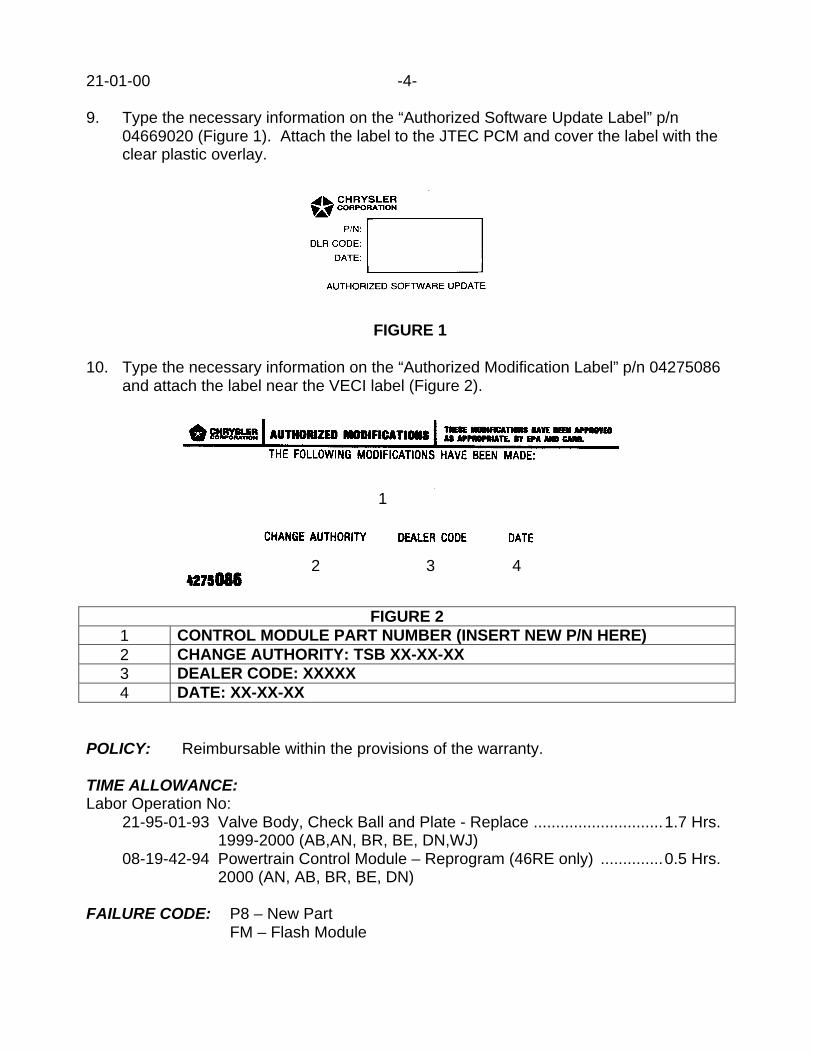
21-01-00 -4-
9. Type the necessary information on the “Authorized Software Update Label” p/n04669020 (Figure 1). Attach the label to the JTEC PCM and cover the label with theclear plastic overlay.
FIGURE 1
10. Type the necessary information on the “Authorized Modification Label” p/n 04275086and attach the label near the VECI label (Figure 2).
1
2 3 4
FIGURE 21 CONTROL MODULE PART NUMBER (INSERT NEW P/N HERE)2 CHANGE AUTHORITY: TSB XX-XX-XX3 DEALER CODE: XXXXX4 DATE: XX-XX-XX
POLICY: Reimbursable within the provisions of the warranty.
TIME ALLOWANCE:Labor Operation No:
21-95-01-93 Valve Body, Check Ball and Plate - Replace .............................1.7 Hrs.1999-2000 (AB,AN, BR, BE, DN,WJ)
08-19-42-94 Powertrain Control Module – Reprogram (46RE only) ..............0.5 Hrs.2000 (AN, AB, BR, BE, DN)
FAILURE CODE: P8 – New PartFM – Flash Module

Form TSB-003 Rev. 1.08 February 3, 2000
NUMBER: 21-02-00
GROUP: Transmission
DATE: March 10, 2000
SUBJECT:47RE Transmission - Delayed Upshift Or No TCC Engagement Between 30 and 50 MPH
OVERVIEW:This bulletin involves the replacement of the transmission valve body upper housingseparator plate.
MODELS:1999 – 2000 (BR/BE) Ram Truck
NOTE: THIS BULLETIN APPLIES TO VEHICLES EQUIPPED WITH A FEDERALMARKET (NAA) 5.9L – 24V DIESEL ENGINE AND BUILT BETWEEN MARCH2, 1999 (MDH 0302XX) AND OCTOBER 1, 1999 (MDH 1001XX).
SYMPTOM/CONDITION:The customer may experience a condition where the transmission may seem to have adelayed 3-4 upshift, while moderately accelerating from 30 to 50 MPH (48 to 80 KM/H).The customer may also note high engine rpm’s while operating in 3rd or 4th gear. Thiscondition may be caused by a delay in the engagement of the transmission torqueconverter clutch (torque converter lockup).
DIAGNOSIS:1. If a delayed upshift condition is experienced, then use the DRB III Scan Tool build a
Custom Display2. Make certain that the ignition switch is in the “ON” position and the engine is not
running.
The following selections may be made by either pressing the corresponding number or bymoving the cursor to the appropriate item and then pressing ENTER key.
3. From the MAIN MENU, select DRB III Standalone (#1).4. From the STAND-ALONE MAIN MENU, select 1998-2001 Diagnostics (#1).5. From the SELECT SYSTEM, select Engine (#1).6. From the ENGINE SELECTION, select JTEC (PCM / Non-Engine) (#2).7. Use the ENTER key to page past the MODULE DISPLAY and the LEARNED
STATUS.8. From the SELECT FUNCTION, select Custom Display (#7).9. From the CUSTOM DISPLAY Menu, select Custom Display #1 (#1).10. From the CUSTOM DISPLAY, select Change (#2).
This bulletin is supplied as technical information only and is not an authorization for repair. No part of this publication may be reproduced, stored in a retrieval system, ortransmitted, in any form or by any means, electronic, mechanical, photocopying, recording, or otherwise, without written permission of DaimlerChrysler Corporation.

21-02-00 -2-
The technician is now able to assemble a custom display from the available Sensors or theInputs/Outputs menus. This is accomplished by placing the cursor on the appropriate rowand pressing the ENTER key. The technician is then offered a choice of the followingmenus: Sensors (#1), Inputs/Outputs (#2), or Not Selected (#3).
Assemble the Custom Display in the following order:1. PCM Engine RPM (found in the Sensors Menu)2. Output Shaft Speed (found in the Sensors Menu)3. Desired TC Clutch (found in the Inputs/Outputs Menu)4. APP Pedal Position Volts (found in the Sensors Menu)5. O/D Off Lamp (found in the Inputs/Outputs Menu)6. Brake Switch (found in the Inputs/Outputs Menu)7. Park/Neutral (found in the Inputs/Outputs Menu)
11. Once the Custom Display has been completely assembled, use the “Page Back” keyto back out of the assembly section of the Custom Display feature.
12. From the Custom Display #1 Menu, select View (#1) to display the list of CustomDisplay values that have been created.
13. Make certain that the engine and transmission are at normal operating temperatures.14. With the ignition switch in the “ON” position and engine stopped, press the O/D
(overdrive) disable button on the shifter handle. This will prevent 4th gear from beingable to be engaged.
15. Verify that the O/D Off Lamp display reads “ON / 3-Speed”.16. Observe the APP Pedal Position Volts and record the value (volts) when the throttle
is closed.
NOTE: TO PERFORM THE DIAGNOSTIC TEST CORRECTLY, THE TECHNICIANMUST ACCELERATE THE VEHICLE WHILE MAINTAINING A SPECIFICTHROTTLE POSITION VOLTAGE (CALLED THE DIAGNOSTIC TEST RANGEVOLTAGE). THE TECHNICIAN MUST PERFORM TWO CALCULATIONS TOOBTAIN THE CORRECT VOLTAGE RANGE TO PERFORM THEDIAGNOSTIC TEST. WITH THE THROTTLE CLOSED, OBTAIN THE “APPPEDAL POSITION VOLTS” READING. THE “APP PEDAL POSITION VOLTS”MUST BE ADDED TO A MINIMUM INITIAL TEST RANGE VOLTAGE AND AMAXIMUM INITIAL TEST VOLTAGE. THE MINIMUM INITIAL TEST RANGEVOLTAGE IS 0.6 VOLTS AND THE MAXIMUM INITIAL TEST RANGEVOLTAGE IS 0.9 VOLTS. ADD THE CLOSED THROTTLE “APP PEDALPOSITION VOLTS” TO EACH OF THE INITIAL TEST RANGE VOLTAGES TOOBTAIN THE DIAGNOSTIC TEST RANGE VOLTAGE.
For example:If the APP Pedal Position Volts at closed throttle is 0.5 volts, then add 0.5 volts to the initialminimum and maximum test range voltages (0.6 volts and 0.9 volts) to obtain thediagnostic test range voltages (1.1 volts to 1.4 volts). The technician would accelerate thevehicle, in this example, while maintaining an APP Pedal Position Voltage of between 1.1volts and 1.4 volts.
-3- 21-02-00
17. Add the APP Pedal Position Volts, at closed throttle, to the minimum and maximuminitial test range voltages to obtain the diagnostic test range voltages.
18. Start the engine. Press the O/D off button to turn off overdrive (prevent 4th gear).
NOTE: THE VEHICLE SHOULD BE DRIVEN IN A SAFE AREA AND IN A SAFEMANNER WHILE PERFORMING THE FOLLOWING DIAGNOSTIC TEST.OBSERVE ALL SPEED LIMITS.
19. Accelerate the vehicle while maintaining the APP Pedal Position Voltage within thediagnostic test range voltage (as calculated in step 17).
20. Verify that the Brake Switch is “Released”, and the Park/Neutral reads “D/R”.21. Verify that the torque converter clutch command is being given. The Desired TC
Clutch must read “LOCKED” within a few seconds after reaching 3rd gear.22. Bring the vehicle to a stop. Accelerate the vehicle while maintaining the diagnostic
test range voltage.22. Continue the vehicle acceleration through the 1 – 2 shift and into the 2 – 3 shift.
Again, make certain that the O/D Off Lamp reads “ON / 3-SPEED”.23. Monitor the Desired TC Clutch, the PCM Engine RPM, and the Output Shaft Speed
values/reading as the transmission shifts from 2nd to 3rd.24. When the “LOCKED” command is given by the PCM to the torque converter clutch
(the Desired TC Clutch value reads “LOCKED”), the PCM Engine RPM and theOutput Shaft Speed should be within +/- 30 rpm of each other within 5 seconds.
25. It may take a 3 or 4 accelerations to obtain a diagnostic conclusion.26. If after 5 seconds following the TCC lockup command, the rpm difference between
the PCM Engine RPM and the Output Shaft Speed is greater then +/- 30 rpm, thenproceed with the Repair Procedure.
PARTS REQUIRED:1 52118048AD Plate, Valve Body Upper Housing Separator1 02464324AB Gasket, Transmission Oil Pan10 05010124AA ATF +3, Transmission Oil (Type 7176E)
EQUIPMENT REQUIRED:1 CH6000 Scan Tool (DRB III)1 CH7000/7001 J1962 Cable
REPAIR PROCEDURE:1. Inspect the new separator plate (p/n 52118048AD). The revised plate will have
additional material removed (see hash marks in Figure 1) creating a wider slot (0.470inch) to allow for increased fluid flow to the torque converter clutch.
2. Clean the separator plate to remove any dirt or rust inhibitor prior to installation.3. Replace the transmission valve body upper housing separator plate and the
transmission oil pan gasket (p/n 02464324AB). Refer to the appropriate year ServiceManual, Section 21 – Transmission and Transfer Case for removal and installationinstructions of the transmission valve body and its upper housing separator plate.
4. Verify fluid level after warming up the transmission and cycling the shift lever severaltimes.
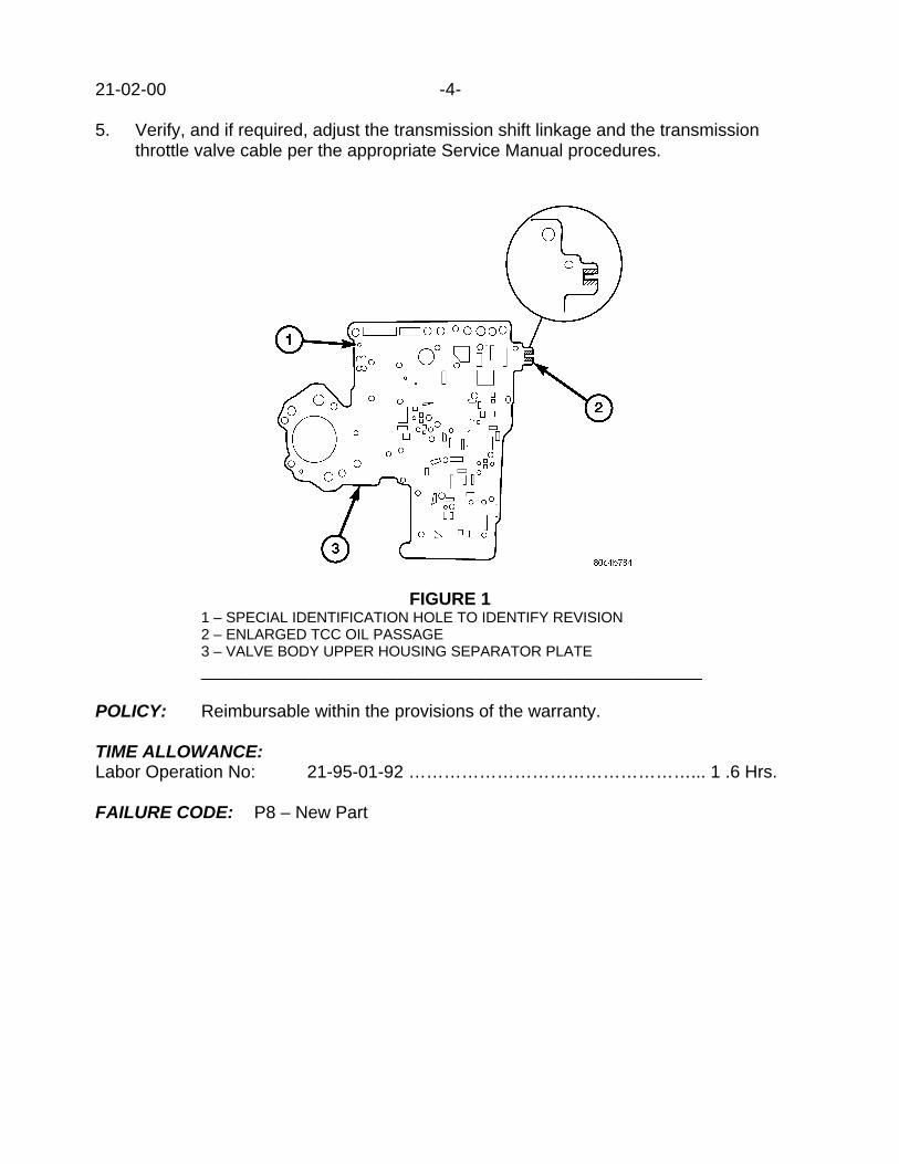
21-02-00 -4-
5. Verify, and if required, adjust the transmission shift linkage and the transmissionthrottle valve cable per the appropriate Service Manual procedures.
FIGURE 11 – SPECIAL IDENTIFICATION HOLE TO IDENTIFY REVISION2 – ENLARGED TCC OIL PASSAGE3 – VALVE BODY UPPER HOUSING SEPARATOR PLATE___________________________________________________
POLICY: Reimbursable within the provisions of the warranty.
TIME ALLOWANCE:Labor Operation No: 21-95-01-92 …………………………………………... 1 .6 Hrs.
FAILURE CODE: P8 – New Part
Form TSB-003 Rev. 1.08 February 3, 2000
NUMBER: 21-03-00
GROUP: Transfer Case
DATE: March 10, 2000
THIS BULLETIN SUPERSEDES TECHNICAL SERVICE BULLETIN 21-22-99, DATEDDEC. 03, 1999, WHICH SHOULD BE REMOVED FROM YOUR FILES. ALL REVISIONSARE HIGHLIGHTED WITH **ASTERISKS** AND INCLUDES ADDITIONAL PARTS.
SUBJECT:NV-242 And NV-242HD Transfer Case Oil Seepage From The Sector Shaft Oil Seal
OVERVIEW:This bulletin involves the installation of a revised sector shaft, sector shaft seal, andrepositioning the current sector shaft bearing on the NV-242 and NV-242HD transfer case.
MODELS:1998 (AN) Dakota1998 (DN) Durango1999 (WJ) Grand Cherokee
NOTE: THIS BULLETIN APPLIES TO VEHICLES EQUIPPED WITH THE NV-242 ORTHE NV-242HD TRANSFER CASE AND ANY GRAND CHEROKEE BUILTBEFORE MARCH 20, 1999 (MDH 0320XX).
SYMPTOM/CONDITION:The customer may complain of a red-in-color oil seepage from under the vehicle. The oilseepage may be localized to the sector shaft seal of the transfer case.
DIAGNOSIS:1). Raise and support the vehicle.2). Determine if the oil seepage is coming from the transfer case sector shaft seal.
If the oil seepage is not from the transfer case sector shaft seal, then additional diagnosisis required. If the oil seepage is from the transfer case sector shaft seal, then perform theRepair Procedure.
PARTS REQUIRED:**1 05014048AA Bolt, Sector Shaft Flange Hex Head**1 05014047AA Sector Shaft, Transfer Case1 05014046AA Sector Shaft Seal1 01664355 Roll Pin, Low Range Fork**1 04798117 Seal, Output Shaft (WJ only)****1 05016615AA Slinger, Rear (WJ only)****1 04798121 Clamp, Boot to Mainshaft (WJ only)****1 04798122 Clamp, Boot to Slip Yoke (WJ only)**2 05010124AA ATF+3, Transfer Case Lubricant (quart)1 82300234 Mopar RTV for Gear Lube (Gray)
This bulletin is supplied as technical information only and is not an authorization for repair. No part of this publication may be reproduced, stored in a retrieval system, ortransmitted, in any form or by any means, electronic, mechanical, photocopying, recording, or otherwise, without written permission of DaimlerChrysler Corporation.

21-03-00 -2-
REPAIR PROCEDURE:1. Raise and support the vehicle. Remove the transfer case from the vehicle. Remove
the sector shaft and seal from the front case of the transfer case. Refer to theappropriate Service Manual, Section 21: Transmission and Transfer Case forremoval, disassembly, assembly and installation instructions.
2. Using a suitable bearing driver, carefully recess the sector shaft bearing to a depth of7.6 – 8.1 mm (0.300 - 0.320 inches). The distance is measured from the top edge /surface of the sector shaft bore to the top of the sector shaft bearing. Figure 1.
FIGURE 1
1 – TOP SURFACE OF SECTOR SHAFT BORE2 – FRONT CASE OF TRANSFER CASE3 – SECTOR SHAFT4 – TOP EDGE OF SECTOR SHAFT BEARING5 – DISTANCE BEARING IS RECESSED INTO BORE____________________________________________
NOTE: DO NOT SCORE OR SCRATCH THE WALL OF THE SECTOR SHAFT BORE.
NOTE: DO NOT RECESS THE BEARING TOO FAR OR CONTACT BETWEEN THEBOTTOM OF THE SECTOR SHAFT BEARING AND THE SECTOR SHAFTWILL OCCUR.
4. Install the new sector shaft (p/n 05014047AA) and sector shaft seal (p/n05014046AA). Make sure that the sector shaft seal is flush with the case.
5. Using the appropriate Service Manual procedures, assemble the transfer case andinstall both the transfer case and the rear propeller shaft.
6. Install transfer case fluid (p/n 05010124AA). Fill the transfer case to the correct level.7. Lower the vehicle.

-3- 21-03-00
POLICY: Reimbursable within the provisions of the warranty.
TIME ALLOWANCE:Labor Operation No: 21-38-04-90 (AN / DN) ……………………..……………………………….…… 2.1 Hrs.
21-38-04-90 (WJ) ………………………………..………………………………. 2.3 Hrs.
FAILURE CODE: P8 – New Part


Form TSB-003 Rev. 1.08 February 3, 2000
NUMBER: 21-04-00
GROUP: Transmission
DATE: June 30, 2000
THIS BULLETIN SUPERSEDES TECHNICAL SERVICE BULLETIN 18-07-99, DATEDAPRIL 30, 1999, WHICH SHOULD BE REMOVED FROM YOUR FILES. ALLREVISIONS ARE HIGHLIGHTED WITH **ASTERISKS** AND INCLUDE REVISEDMODEL YEARS.
SUBJECT:Erroneous MIL Illumination For P1763 – Trans. Governor Pressure Sensor Volts Too High
OVERVIEW:This bulletin involves selectively erasing and reprogramming the JTEC Powertrain ControlModule (PCM) with new software (calibration change 96Cal18, 97Cal18, 98Cal12, and99Cal14).
MODELS:**1996** – 1999 (AB) Ram Van**1996** – 1999 (AN) Dakota**1996** – 1999 (BR/BE) Ram Truck 1998 – 1999 (DN) Durango**1997** – 1999 (TJ) Wrangler**1996** – 1999 (XJ) Cherokee**1996** – 1998 (ZJ) Grand Cherokee
NOTE: THIS INFORMATION APPLIES TO VEHICLES EQUIPPED WITH AN RESERIES AUTOMATIC TRANSMISSION BUILT BEFORE DECEMBER 18, 1998(MDH 1218XX).
SYMPTOM/CONDITION:Some vehicles may exhibit a MIL illumination with a Diagnostic Trouble Code (DTC) ofP1763 – Transmission Governor Pressure Sensor Volts Too High. The vehicle operatormay experience slower than normal vehicle accelerations because the transmission mayhave temporarily entered its third gear “Limp-In” mode as a result of the DTC. The “Limp-In” mode may last until the vehicle owner cycles the ignition key. The technician may notdetect a problem with the automatic transmission during a diagnostic test or test drive.
The MIL is caused by an increase in hydraulic pressure. The increased hydraulic pressureis the result of a new valve body machining process, which entered into productionJanuary 1, 1998. This condition will occur most often with vehicles that were built betweenJanuary 1, 1998 and December 18, 1998.
Vehicles built prior to January 1, 1998 may also experience this condition if the valve bodyor the transmission assembly is replaced with components built after January 1, 1998.
This bulletin is supplied as technical information only and is not an authorization for repair. No part of this publication may be reproduced, stored in a retrieval system, ortransmitted, in any form or by any means, electronic, mechanical, photocopying, recording, or otherwise, without written permission of DaimlerChrysler Corporation.

21-04-00 -2-
DIAGNOSIS:Using the Mopar Diagnostic System (MDS2) and or the Diagnostic Scan Tool (DRB III),with the appropriate Diagnostic Procedures Manual, verify that all engine and transmissionsystems are functioning as designed. If Diagnostic Trouble Codes (DTC’s) are present,record them on the repair order and repair as necessary before proceeding further with thisbulletin. If no DTC’s are present, and the above symptom has been experienced, performthe Repair Procedure.
NOTE: WHENEVER A POWERTRAIN (PCM) IS REPLACED DUE TO FAILURE, THESOFTWARE OF THE REPLACEMENT CONTROLLER MUST BE VERIFIEDFOR THE LATEST REVISION LEVEL. USE THE FLASH PROCEDURE TOUPDATE REPLACED CONTROLLERS AS NECESSARY.
PARTS REQUIRED:1 04669020 Label, Authorized Software Update1 04275086 Label, Authorized Modification
EQUIPMENT REQUIRED:1 CH6000 Scan Tool (DRB III)1 CH7035 General Purpose Interface Bus Cable (GPIB)1 CH7000/7001 J1962 Cable1 MDS2
NOTE: THE MDS2 AND DRB III ARE REQUIRED TO PERFORM PART OF THISREPAIR. WHEN USING THE MDS2 AND THE DRB III, THE SYSTEM MUSTBE OPERATING AT CIS CD 2061 OR HIGHER.
REPAIR PROCEDURE:1. Log onto the MDS2 system.2. Connect the MDS2 and DRB III to the vehicle and switch the ignition key to “ON”.3. Use the arrow keys and select #2 CONNECT TO MDS2 on the DRB III MAIN MENU
SCREEN.4. Use the arrow keys and select #2 RUN MDS2 APPLICATION on the DRB III MAIN
MENU SCREEN.
NOTE: ONCE MDS2, DRB III, AND VEHICLE COMMUNICATION HAS BEENESTABLISHED, THE “CANNOT READ VIN FROM DRB III” MESSAGE (ONTHE MDS2) WILL BE REPLACED BY THE VEHICLE VIN. PRESS THE “OK”BUTTON ON THE MDS2 TO REQUEST A MDS2 SESSION FOR THEVEHICLE VIN INDICATED. PRESS THE “OK” BUTTON WHEN ASKED TOBEGIN SESSION.
5. Select the FLASH tab on the MDS2.6. Select READ PART NUMBERS FROM VEHICLE and click SHOW UPDATES on the
MDS2. Press the “OK” button.

-3- 21-04-00
NOTE: IN ABOVE STEPS #5 AND/OR #6, A MESSAGE MAY APPEAR THATINDICATES NO UPDATES ARE AVAILABLE. IF THIS OCCURS, MAKESURE YOUR DIAGNOSTIC EQUIPMENT IS OPERATING AT THE LATESTSOFTWARE LEVEL AS LISTED EARLIER IN THIS BULLETIN. IF THELATEST SOFTWARE IS INSTALLED, AND NO UPDATES ARE AVAILABLE,ANOTHER VEHICLE CONDITION EXISTS THAT WILL REQUIRE FURTHERINVESTIGATION.
7. Select the new software part number with the light pen and click UPDATECONTROLLER SOFTWARE.
8. The MDS2 and DRB III will prompt for any operator action needed during theremainder of the reprogramming process.
NOTE: DUE TO THE PCM REPROGRAMMING PROCEDURE, A DTC MAY BE SETIN OTHER MODULES (EATX, BCM, MIC, SKIM) WITHIN THE VEHICLE, IFSO EQUIPPED. SOME DTC’S MAY CAUSE THE MIL TO ILLUMINATE. ALLDTC’S RELATE TO A LOSS OF COMMUNICATIONS WITH THE MODULETHAT IS BEING REPROGRAMMED. CHECK ALL MODULES, RECORD THEFAULTS, AND ERASE THESE FAULTS PRIOR TO RETURNING THEVEHICLE TO THE CUSTOMER. ERASE ANY FAULTS IN THE PCM ONLYAFTER ALL OTHER MODULES HAVE HAD THEIR FAULTS ERASED.
NOTE: THE FOLLOWING STEPS ARE REQUIRED BY LAW.
9. Type the necessary information on the “Authorized Software Update Label” p/n04669020 (Figure 1). Attach the label to the JTEC PCM and cover the label with the clearplastic overlay.
FIGURE 1____________________
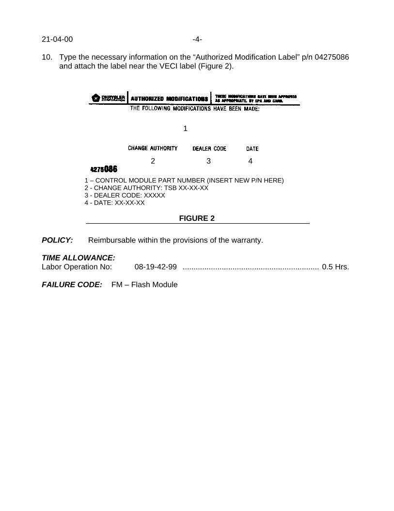
21-04-00 -4-
10. Type the necessary information on the “Authorized Modification Label” p/n 04275086and attach the label near the VECI label (Figure 2).
1
2 3 4
1 – CONTROL MODULE PART NUMBER (INSERT NEW P/N HERE)2 - CHANGE AUTHORITY: TSB XX-XX-XX3 - DEALER CODE: XXXXX4 - DATE: XX-XX-XX
FIGURE 2
POLICY: Reimbursable within the provisions of the warranty.
TIME ALLOWANCE:Labor Operation No: 08-19-42-99 ............................................................... 0.5 Hrs.
FAILURE CODE: FM – Flash Module

Form TSB-004 Rev. 1.06 February 3, 2000
NUMBER: 21-05-00
GROUP: Transmission
DATE: July 28, 2000
SUBJECT:All Wheel Drive Power Transfer Unit Failure
MODELS:1996 – 2000 (NS) Town & Country/Caravan/Voyager1996 – 2000 (GS) Chrysler Voyager (International Markets)2001 (RS) Town & Country/Caravan/Voyager2001 (RG) Chrysler Voyager (International Markets)
DISCUSSION:The All Wheel Drive (AWD) system used on Minivans uses a Power Transfer Unit (PTU)that connects the front drive components to the rear drive components. The PTU may failif identical tires are not used on all four wheels. This kind of PTU failure is the result ofextreme heat build up caused by a continuous difference of rotation speeds and torquetransfer between the front and rear drive components when different size tires are used onthe front wheels versus the rear wheels.
A difference in tire circumference measurements as small as 0.5% is enough to cause aPTU failure. PTU failures related to mismatched tires are not warrantable.
Important points to be remembered and to remind AWD minivan vehicle operators:• Tires should be rotated every 7,500 miles or less to maintain even tread wear.• Correct tire air pressure must be maintained.• When tire replacement is necessary all 4 tires must be replaced with a matched (same
manufacturer, model, and size) set.
POLICY: Information Only
This bulletin is supplied as technical information only and is not an authorization for repair. No part of this publication may be reproduced, stored in a retrieval system, ortransmitted, in any form or by any means, electronic, mechanical, photocopying, recording, or otherwise, without written permission of DaimlerChrysler Corporation.


Form TSB-004 Rev. 1.06 February 3, 2000
NUMBER: 21-06-00
GROUP: Transfer Case
DATE: August 18, 2000
SUBJECT:Electronic Shift Transfer Case Features And Operating Characteristics
MODELS:2001 (AN) Dakota2001 (DN) Durango
NOTE: THIS BULLETIN APPLIES TO VEHICLES EQUIPPED WITH A NV244 ORNV233 TRANSFER CASE.
DISCUSSION:For the 2001 model year, the method of shifting either the new NV244 All Wheel Drive(AWD) transfer case or the new NV233 Part Time Drive transfer case has been revised.Instead of a manually operated shift lever to select a different shift mode or range, anelectronic control switch is now used. The control switch will signal the Transfer CaseControl Module (TCCM) to shift the transfer case into or out of the 4HI mode from eitherthe 2WD or AWD mode. The control switch will also signal the TCCM to shift into and outof the 4HI to 4LO range.
The transfer case control switch is located on the instrument panel. With the removal ofthe manual shift lever, the floor tunnel area is now less obstructed. The control switch iseasier and more convenient to use. The capability to shift the transfer case electronicallyallows for future integration of the transfer case with other vehicle systems.
Like their predecessors in prior years, the new NV244 and NV233 transfer cases are notsynchronized. This means that gear clash or clunk-like sounds may be noticed whentransfer case shifting occurs. The gear clash/clunk-like sound will be most noticeablewhen shifting into or out of the 4LO range on automatic transmission equipped vehicles.Because of neutral drag on the transmission output shaft, by other components inside theautomatic transmission, the output shaft may continue to rotate while the 4LO gears arebeing engaged or disengaged. A clash/clunk-like sound will be the normal result.
Shifting from the AWD or 2WD mode into the 4HI mode, and vise versa, will normallyoccur within five seconds. Shifting between these two modes normally generates only asmall amount of sound.
There is normally a delay of up to 15 seconds when shifting into or out of 4LO, but a delayof 30 seconds may be possible. The shift delay occurs due to the transfer case internalgears not being lined up, or when the gears are torque bound (spline locked) at the time ofthe shift. When this happens, the system stops and attempts to execute the shiftcommand again. The system will attempt to shift five (5) times, at 5+ seconds per shiftattempt. After the fifth attempt, the system must be reset. The reset is accomplished byre-selecting the original position for a couple seconds. After this, a new shift can berequested.
This bulletin is supplied as technical information only and is not an authorization for repair. No part of this publication may be reproduced, stored in a retrieval system, ortransmitted, in any form or by any means, electronic, mechanical, photocopying, recording, or otherwise, without written permission of DaimlerChrysler Corporation.

21-06-00 -2-
NOTE: REFER TO THE APPROPRIATE 2001 DAKOTA OR DURANGO SERVICEMANUAL – GROUP 8E, ELECTRONIC CONTROL MODULES / TRANSFERCASE CONTROL MODULE, FOR A COMPLETE EXPLANATION OF THESEQUENCE OF EVENTS AND TIMING DURING A SHIFT.
Once the shift has been made after the delay, the customer may become concerned withthe 4LO gear clash/clunk-like sound, because it has occurred several seconds after theshift has been selected/requested. Though the gear clash/clunk was present with previousmodel year transfer cases, which used a manually operated shift lever to engage 4LO, thelow range shift delay with the electric transfer case is new. The customer may notassociate the delayed gear clash/clunk-like sound with their previous low range shiftrequest/selection.
FIGURE 11 – Maximum sweep of the transfer case switch/knob2 – Transfer case switch3 – Neutral mode button_________________________________________
The transfer case control switch knob can select three mode/range positions only. For theNV244 transfer case those positions are: AWD, 4HI, or 4LO. For the NV233 transfer casethe positions are: 2WD, 4HI, or 4LO (Figure 1).
NOTE: REFER TO THE APPROPRIATE 2001 DAKOTA OR DURANGO OWNERSMANUAL AND/OR 2001 DAKOTA OR DURANGO SERVICE MANUAL FORDETAILED INSTRUCTIONS REGARDING PROPER SHIFT PROCEDURES.

-3- 21-06-00
The transfer case control switch knob CAN NOT be rotated to select the Neutral mode. ANEUTRAL MODE BUTTON must be depressed to select the Neutral mode (Figure 1).The customer may mistakenly attempt to rotate the control switch knob in an attempt toselect Neutral mode. The Neutral mode MUST be used to flat tow the vehicle (i.e. when allfour wheels are on the ground).
NOTE: REFER TO THE APPROPRIATE DAKOTA OR DURANGO OWNERSMANUAL FOR DETAILED INSTRUCTIONS AND PRECAUTIONSREGARDING PROPER TOWING PROCEDURES.
POLICY: Information Only

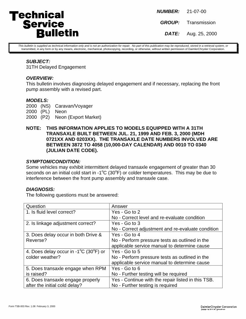
Form TSB-003 Rev. 1.08 February 3, 2000
NUMBER: 21-07-00
GROUP: Transmission
DATE: Aug. 25, 2000
SUBJECT:31TH Delayed Engagement
OVERVIEW:This bulletin involves diagnosing delayed engagement and if necessary, replacing the frontpump assembly with a revised part.
MODELS:2000 (NS) Caravan/Voyager2000 (PL) Neon2000 (P2) Neon (Export Market)
NOTE: THIS INFORMATION APPLIES TO MODELS EQUIPPED WITH A 31THTRANSAXLE BUILT BETWEEN JUL. 21, 1999 AND FEB. 3, 2000 (MDH0721XX AND 0203XX). THE TRANSAXLE DATE NUMBERS INVOLVED AREBETWEEN 3872 TO 4058 (10,000-DAY CALENDAR) AND 0010 TO 0340(JULIAN DATE CODE).
SYMPTOM/CONDITION:Some vehicles may exhibit intermittent delayed transaxle engagement of greater than 30seconds on an initial cold start in -1oC (30oF) or colder temperatures. This may be due tointerference between the front pump assembly and transaxle case.
DIAGNOSIS:The following questions must be answered:
Question Answer1. Is fluid level correct? Yes - Go to 2
No - Correct level and re-evaluate condition2. Is linkage adjustment correct? Yes - Go to 3
No - Correct adjustment and re-evaluate condition3. Does delay occur in both Drive &Reverse?
Yes - Go to 4No - Perform pressure tests as outlined in theapplicable service manual to determine cause
4. Does delay occur in -1oC (30oF) orcolder weather?
Yes - Go to 5No - Perform pressure tests as outlined in theapplicable service manual to determine cause
5. Does transaxle engage when RPMis raised?
Yes - Go to 6No - Further testing will be required
6. Does transaxle engage properlyafter the initial cold delay?
Yes - Continue with the repair listed in this TSB.No - Further testing is required
This bulletin is supplied as technical information only and is not an authorization for repair. No part of this publication may be reproduced, stored in a retrieval system, ortransmitted, in any form or by any means, electronic, mechanical, photocopying, recording, or otherwise, without written permission of DaimlerChrysler Corporation.

21-07-00 -2-
If the answers to the above questions were YES, the most likely cause of the condition isdue to interference between the pump housing and transaxle case. Perform the followingRepair Procedure. If the answers were NO, further diagnosis will be required to determinethe cause of the condition.
PARTS REQUIRED:1 05016410AB Assembly, Front Pump1 04269661AB Gasket, Front PumpAR 05013457AA Quarts, ATF +4 (Type 9602)
REPAIR PROCEDURE:
1. Using the procedures outlined in the applicable service manual, replace the frontpump with p/n 05016410AB.
POLICY: Reimbursable within the provisions of the warranty.
TIME ALLOWANCE:Labor Operation No: 21-60-05-92 NS Models...............................................3.6 Hrs.
PL/P2 Models ..........................................2.8 Hrs.
FAILURE CODE: P8 - New Part
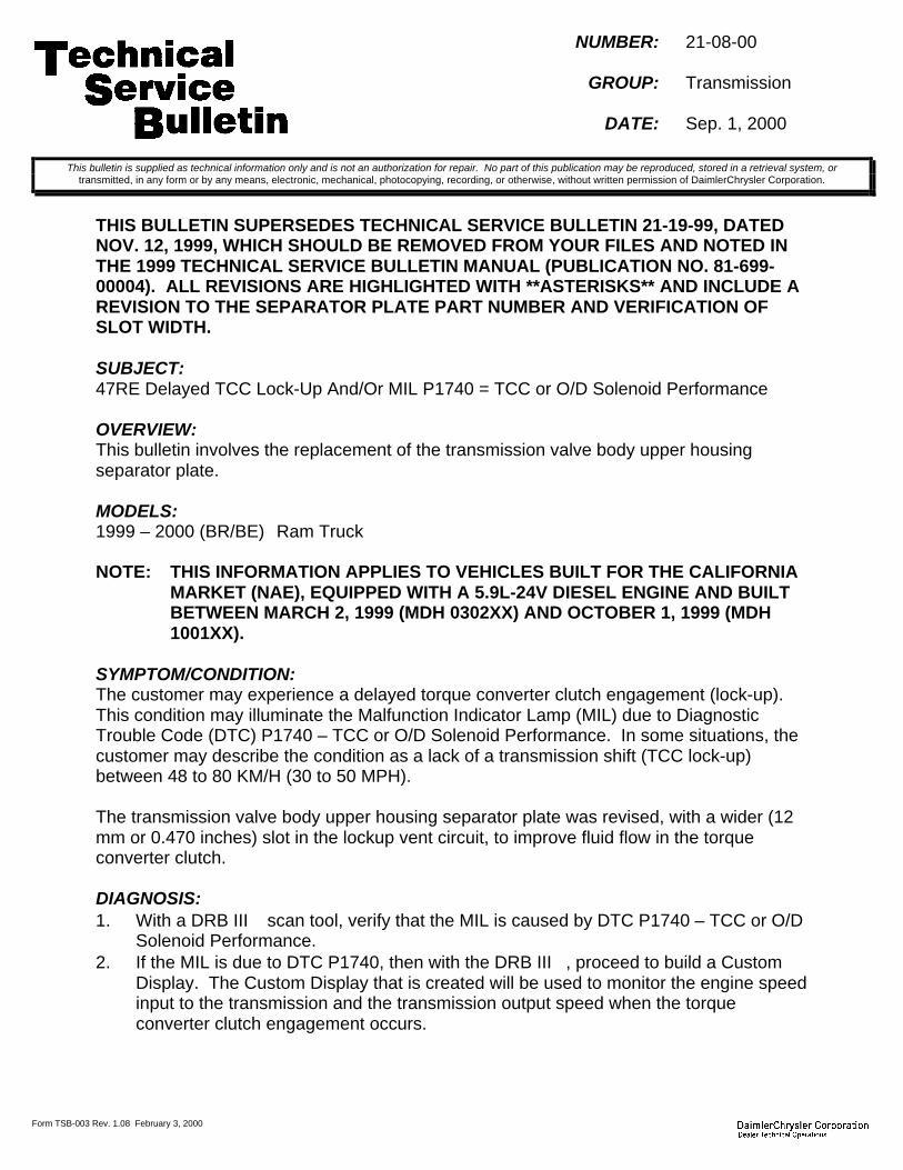
Form TSB-003 Rev. 1.08 February 3, 2000
NUMBER: 21-08-00
GROUP: Transmission
DATE: Sep. 1, 2000
THIS BULLETIN SUPERSEDES TECHNICAL SERVICE BULLETIN 21-19-99, DATEDNOV. 12, 1999, WHICH SHOULD BE REMOVED FROM YOUR FILES AND NOTED INTHE 1999 TECHNICAL SERVICE BULLETIN MANUAL (PUBLICATION NO. 81-699-00004). ALL REVISIONS ARE HIGHLIGHTED WITH **ASTERISKS** AND INCLUDE AREVISION TO THE SEPARATOR PLATE PART NUMBER AND VERIFICATION OFSLOT WIDTH.
SUBJECT:47RE Delayed TCC Lock-Up And/Or MIL P1740 = TCC or O/D Solenoid Performance
OVERVIEW:This bulletin involves the replacement of the transmission valve body upper housingseparator plate.
MODELS:1999 – 2000 (BR/BE) Ram Truck
NOTE: THIS INFORMATION APPLIES TO VEHICLES BUILT FOR THE CALIFORNIAMARKET (NAE), EQUIPPED WITH A 5.9L-24V DIESEL ENGINE AND BUILTBETWEEN MARCH 2, 1999 (MDH 0302XX) AND OCTOBER 1, 1999 (MDH1001XX).
SYMPTOM/CONDITION:The customer may experience a delayed torque converter clutch engagement (lock-up).This condition may illuminate the Malfunction Indicator Lamp (MIL) due to DiagnosticTrouble Code (DTC) P1740 – TCC or O/D Solenoid Performance. In some situations, thecustomer may describe the condition as a lack of a transmission shift (TCC lock-up)between 48 to 80 KM/H (30 to 50 MPH).
The transmission valve body upper housing separator plate was revised, with a wider (12mm or 0.470 inches) slot in the lockup vent circuit, to improve fluid flow in the torqueconverter clutch.
DIAGNOSIS:1. With a DRB III scan tool, verify that the MIL is caused by DTC P1740 – TCC or O/D
Solenoid Performance.2. If the MIL is due to DTC P1740, then with the DRB III, proceed to build a Custom
Display. The Custom Display that is created will be used to monitor the engine speedinput to the transmission and the transmission output speed when the torqueconverter clutch engagement occurs.
This bulletin is supplied as technical information only and is not an authorization for repair. No part of this publication may be reproduced, stored in a retrieval system, ortransmitted, in any form or by any means, electronic, mechanical, photocopying, recording, or otherwise, without written permission of DaimlerChrysler Corporation.

21-08-00 -2-
3. The Custom Display should include the following sensors and input/output displays:a. PCM Engine RPM (found in the Sensors Menu)b. Output Shaft Speed (found in the Sensors Menu)c. Desired TC Clutch (found in the Inputs/Outputs Menu)d. APP Pedal Position Volts (found in the Sensors Menu)e. O/D Off Lamp (found in the Inputs/Outputs Menu)f. Brake Switch (found in the Inputs/Outputs Menu)g. Park/Neutral (found in the Inputs/Outputs Menu)
4. Save the Custom Display for use during the road test portion of the diagnosis.
ROAD TEST:1. Start the engine.2. With the DRB III, bring up the Custom Display that was created for this condition.3. Make certain that the engine and transmission are at normal operating temperatures.4. Press the O/D button on the shifter handle. This will prevent O/D engagement.5. Verify on the Custom Display that the O/D Off Lamp display reads “ON / 3-SPEED”.6. Observe the APP Pedal Position Volts. Record the voltage value when the throttle is
closed and the engine is at idle. This value is required to calculate how wide openthe throttle must be when verifying TCC lock-up during the diagnostic road test.
When the diagnostic test is actually performed, the closed throttle (at idle) APP PedalPosition voltage must be added to the initial minimum and maximum test range voltages.The initial test range voltages are 0.6 volts (min.) and 0.9 volts (max.). Add the at idleclosed throttle voltage from Step 6, to each of the initial test range voltages to obtain theactual test range voltages.
An example: if the APP Pedal Position Voltage at closed throttle (and engine idling) is 0.5volts, then add this reading (0.5 volts) to the initial test range voltages (0.6 volts and 0.9volts) to obtain the actual diagnostic test range voltages of 1.1 volts and 1.4 voltsrespectively. In this example, the technician would accelerate the vehicle whilemaintaining an APP Pedal Position Voltage of between 1.1 volts (min.) and 1.4 volts(max.).
7. Add the APP Pedal Position voltage obtained in Step 6, to the initial test rangevoltages (0.6 volts and 0.9 volts) to obtain the actual diagnostic test range voltages.
8. Accelerate the vehicle while maintaining the APP Pedal Position Voltage within theactual diagnostic test range (as calculated in step 7).
NOTE: THE VEHICLE MUST BE DRIVEN IN A SAFE AREA AND IN A SAFEMANNER WHILE PERFORMING THE FOLLOWING DIAGNOSTIC TEST.OBSERVE ALL SPEED LIMITS.
9. Verify that the Brake Switch is “Released”, and that the Park/Neutral reads “D/R”.10. Verify that the torque converter clutch command is being given. The Desired TC
Clutch must read “LOCKED” within a few seconds of reaching 3rd gear.

-3- 21-08-00
11. Bring the vehicle to a stop with engine idling. Accelerate the vehicle whilemaintaining the APP Pedal Position voltage within the actual diagnostic test rangevoltages that were calculated in Step 7.
12. Continue to accelerate the vehicle through the 1-2 upshift and into the 2-3 upshift.Again, make certain that the O/D Off Lamp reads “ON / 3-SPEED”.
13. Monitor the Desired TC Clutch, the PCM Engine RPM, and the Output Shaft Speedvalues/readings as the transmission upshifts from 2nd to 3rd.
14. The PCM Engine RPM and the Output Shaft Speed values should be within +/- 30rpm of each other within 6 seconds following the command from the PCM to lockupthe torque converter clutch (Desired TC Clutch reads “LOCKED”).
15. It may take three or four accelerations (Steps 11 through 14) to obtain a gooddiagnostic conclusion.
16. If the rpm difference between the PCM Engine RPM value/reading and the OutputShaft Speed value/reading is greater than +/- 30 rpm after 6 seconds following TCClock-up in 3rd gear, then perform the Repair Procedure. If the difference before 6seconds is less than + / - 30 rpm, then further diagnosis is required.
PARTS REQUIRED:**1 52118048AD Plate, Valve Body Upper Housing Separator****1 02464324AB Gasket, Transmission Oil Pan**AR (10) 05010124AA ATF+3, Transmission Oil Type 7176
EQUIPMENT REQUIRED:CH6000 Scan Tool (DRB III)CH7000/7001 J1962 Cable
REPAIR PROCEDURE:
1. Inspect the new valve body separator plate, **p/n 52118048AD**. The new plateshould have a **12 mm or 0.470 in.** wide slot for the torque converter clutch lock-upvent circuit (Figure 1).
NOTE: VERIFY THAT THE SLOT SHOWN IN FIGURE 1 IS APPROXIMATELY 12 MM(0.470 IN.) WIDE. IF SLOT IS APPROXIMATELY 3 MM WIDE, THEN THEPLATE IS INCORRECT.
2. Clean the separator plate to remove any dirt or rust inhibitor prior to installation.3. Replace the transmission valve body upper housing separator plate and the
transmission oil pan gasket, **p/n 02464324AB**. Refer to the appropriate yearService Manual, Group 21 – Transmission and Transfer Case, for removal andinstallation instructions regarding the transmission valve body and its upper housingseparator plate.
4. Verify transmission fluid level after warming up the transmission and cycling the shiftlever several times.
5. Verify, and if required, adjust the transmission shift linkage and the transmissionthrottle valve cable per the appropriate Service Manual procedures.
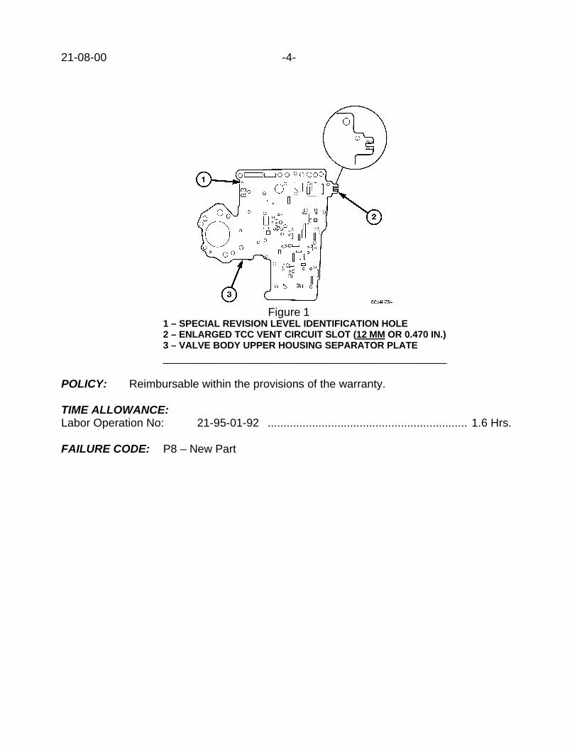
21-08-00 -4-
Figure 11 – SPECIAL REVISION LEVEL IDENTIFICATION HOLE2 – ENLARGED TCC VENT CIRCUIT SLOT (12 MM OR 0.470 IN.)3 – VALVE BODY UPPER HOUSING SEPARATOR PLATE_____________________________________________
POLICY: Reimbursable within the provisions of the warranty.
TIME ALLOWANCE:Labor Operation No: 21-95-01-92 ............................................................... 1.6 Hrs.
FAILURE CODE: P8 – New Part
Form TSB-003 Rev. 1.08 February 3, 2000
NUMBER: 21-09-00
GROUP: Transmission
DATE: Sep. 15, 2000
THIS BULLETIN SUPERSEDES TECHNICAL SERVICE BULLETIN 21-12-99, DATEDSEPT. 03, 1999, WHICH SHOULD BE REMOVED FROM YOUR FILES AND NOTED INTHE 1999 TECHNICAL SERVICE BULLETIN MANUAL (PUBLICATION NO. 81-699-00004). THIS IS A COMPLETE REVISION AND NO ASTERISKS HAVE BEEN USEDTO HIGHLIGHT REVISIONS.
SUBJECT:45RFE Transmission Quality Enhancements For The 1-2, 2-3, and 4-3 Shifts
OVERVIEW:This bulletin involves selectively erasing and reprogramming the Dakota, the Durango, orthe Grand Cherokee Transmission Control Module or TCM (with calibration 99Ver9.0,00Ver8.5, or 00Ver9.0). And as required, reprogramming the Grand Cherokee PowertrainControl Module or PCM (with calibration 99Cal19A or 00Cal16A).
MODELS:2000 (AN) Dakota2000 (DN) Durango1999 – 2000 (WJ) Grand Cherokee
NOTE: THIS BULLETIN APPLIES TO VEHICLES EQUIPPED WITH A 4.7L ENGINEAND A 45RFE AUTOMATIC TRANSMISSION BUILT BEFORE AUGUST 16,1999 (MDH 0816XX).
SYMPTOM/CONDITION:Some vehicles equipped with a 45RFE transmission may experience the following shiftquality issues:
1. A harsh 2-3 upshift causing a powertrain clunk or shudder when accelerating.2. A harsh 1-2 upshift during light or wide open throttle accelerations.3. A harsh 4-3 kickdown shift during low speed, light throttle conditions.
NOTE: THE REVISION TO THE TCM SOFTWARE ADDRESSES THE ABOVE SHIFTQUALITY CONDITIONS FOR ALL VEHICLES, AND ADDS A FINAL GEARRATIO TO THE GRAND CHEROKEE TRANSMISSION ONLY.
NOTE: TO MAINTAIN EMISSIONS COMPLIANCE, GRAND CHEROKEE VEHICLESTHAT ARE EQUIPPED WITH A FEDERAL EMISSION SYSTEM (SALESCODE NAA) MUST HAVE THEIR PCM REPROGRAMMED IF THE CURRENTPCM CALIBRATION LEVEL IS EARLIER THAN 99CAL19A (FOR A 1999 M.Y.VEHICLE) OR 00CAL16A (FOR A 2000 M.Y. VEHICLE). REPROGRAMMINGIS NOT REQUIRED IF THE PCM SOFTWARE IS ALREADY AT ONE OFTHESE LEVELS OR LATER (A HIGHER CAL NUMBER), OR IF THE GRANDCHEROKEE HAS A CALIFORNIA EMISSION SYSTEM (SALES CODE NAE).
This bulletin is supplied as technical information only and is not an authorization for repair. No part of this publication may be reproduced, stored in a retrieval system, ortransmitted, in any form or by any means, electronic, mechanical, photocopying, recording, or otherwise, without written permission of DaimlerChrysler Corporation.

21-09- 00 -2-
DIAGNOSIS:Using the Mopar Diagnostic System (MDS2) and or the Diagnostic Scan Tool (DRB III),with the appropriate Diagnostic Procedures Manual, verify that all engine and transmissionsystems are functioning as designed. If Diagnostic Trouble Codes (DTC’s) are present,record them on the repair order and repair as necessary before proceeding further with thisbulletin. If no DTC’s are present, and the above symptom has been experienced, performthe Repair Procedure.
NOTE: FOR THE 1999 OR 2000 GRAND CHEROKEE VEHICLES, IF ADDITIONALASSISTANCE IS REQUIRED ONCE THE TCM HAS BEEN REPROGRAMMEDWITH THE REVISED SOFTWARE 99VER9.0 OR 00VER9.0 (OR LATER),THEN REFER TO THE 2001 JEEP GRAND CHEROKEE POWERTRAINDIAGNOSTIC PROCEDURES MANUAL (81-699-01060) AND/OR TO THE2001 JEEP GRAND CHEROKEE SERVICE MANUAL (81-370-1047).
NOTE: WHENEVER A PCM OR TCM IS REPLACED DUE TO FAILURE, THESOFTWARE OF THE REPLACEMENT CONTROLLER MUST BE VERIFIEDFOR THE LATEST REVISION LEVEL. USE THE FLASH PROCEDURE TOUPDATE REPLACED CONTROLLERS AS NECESSARY.
PARTS REQUIRED:2 04669020 Label, Authorized Software Update1 04275086 Label, Authorized Modification
EQUIPMENT REQUIRED:1 CH6000 Scan Tool (DRB III)1 CH7035 General Purpose Interface Bus Cable (GPIB)1 CH7000/7001 J1962 Cable1 MDS2
NOTE: THE MDS2 AND DRB III ARE REQUIRED TO PERFORM PART OF THISREPAIR. WHEN USING THE MDS2 AND THE DRB III, THE SYSTEM MUSTBE OPERATING AT CIS CD 2062 OR HIGHER.
REPAIR PROCEDURE:
TCM and PCM Reprogramming:
NOTE: ONLY THE 1999 AND 2000 GRAND CHEROKEE VEHICLES, WITH AFEDERAL EMISSIONS SYSTEM (NAA) AND PCM SOFTWARE THAT ISEARLIER THAN CALIBRATION LEVEL 99CAL19A (FOR 1999 M.Y.) OR00CAL16A (FOR 2000 M.Y.), REQUIRE PCM REPROGRAMMING. VERIFYTHE CURRENT CALIBRATION LEVEL OF THE PCM.
1. Log onto the MDS2 system.2. Connect the MDS2 and DRB III to the vehicle and switch the ignition key to “ON”.

-3- 21-09-00
NOTE: AUTO CONNECTION WILL OCCUR ONCE THE DRB III, MDS2, ANDVEHICLE ESTABLISH COMMUNICATION. THE “CANNOT READ VIN FROMDRB III” MESSAGE (ON THE MDS2) WILL BE REPLACED BY THEVEHICLE VIN. PRESS THE “OK” BUTTON ON THE MDS2 TO REQUEST AMDS2 SESSION FOR THE VEHICLE VIN INDICATED. PRESS THE “OK”BUTTON WHEN ASKED TO BEGIN SESSION.
3. Select the FLASH tab on the MDS2.4. Select READ PART NUMBERS FROM VEHICLE and click SHOW UPDATES on the
MDS2.
NOTE: A MESSAGE MAY APPEAR (AFTER STEPS 3 OR 4) THAT INDICATES NOUPDATES ARE AVAILABLE. IF THIS OCCURS, MAKE SURE YOURDIAGNOSTIC EQUIPMENT IS OPERATING AT THE LATEST SOFTWARELEVEL AS LISTED EARLIER IN THIS BULLETIN. IF THE LATESTSOFTWARE IS INSTALLED, AND NO UPDATES ARE AVAILABLE,ANOTHER VEHICLE CONDITION EXISTS THAT WILL REQUIRE FURTHERINVESTIGATION.
5. Select the new software part number with the light pen and click UPDATECONTROLLER SOFTWARE.
6. The MDS2 and DRB III will prompt for any operator action needed during theremainder of the reprogramming process.
NOTE: DUE TO THE TCM AND/OR PCM REPROGRAMMING PROCEDURE, A DTCMAY BE SET IN OTHER MODULES (PCM, TCM, BCM, MIC, SKIM, ETC.)WITHIN THE VEHICLE, IF SO EQUIPPED. SOME MAY CAUSE THE MIL TOILLUMINATE. ALL DTC’S RELATE TO A LOSS OF COMMUNICATIONSWITH THE MODULE THAT IS BEING REPROGRAMMED. CHECK ALLMODULES, RECORD THE FAULTS, AND ERASE THESE FAULTS PRIORTO RETURNING THE VEHICLE TO THE CUSTOMER. ERASE ANY FAULTSIN THE PCM ONLY AFTER ALL OTHER MODULES HAVE HAD THEIRFAULTS ERASED.
NOTE: PERFORM A QUICK LEARN OF THE TRANSMISSION ONCEREPROGRAMMING OF THE TCM (AND PCM) IS COMPLETED.
NOTE: THE FOLLOWING STEPS ARE REQUIRED BY LAW.
7. Type the necessary information on the “Authorized Software Update Label” p/n04669020 (Figure 1). Attach one label to the EATX TCM, and one label to the WJPCM (if it was reprogrammed), and cover the label(s) with the clear plastic overlay.

21-09-00 -4-
FIGURE 1________________________
8. Type the necessary information on the “Authorized Modification Label” p/n 04275086and attach the label near the VECI label (Figure 2).
1
2 3 4
FIGURE 21 – CONTROL MODULE PART NUMBER (INSERT NEW P/N HERE)2 - CHANGE AUTHORITY: TSB XX-XX-XX3 - DEALER CODE: XXXXX4 - DATE: XX-XX-XX
POLICY: Reimbursable within the provisions of the warranty.
TIME ALLOWANCE:Labor Operation No:
08-19-50-98 (Reprogram TCM) ……………………………………………….. 0.5 Hrs.**08-19-44-94 (Reprogram WJ PCM – Federal Emissions Only) ……..... 0.5 Hrs.**
FAILURE CODE: FM – Flash Module

Form TSB-003 Rev. 1.08 February 3, 2000
NUMBER: 21-10-00
GROUP: Transmission
DATE: Sep. 15, 2000
SUBJECT:47RE Harsh Engagement When The Torque Converter Clutch Is Applied
OVERVIEW:This bulletin involves the replacement of the transmission valve body upper housingseparator plate.
MODELS:2000 - 2001 (BR/BE) Ram Truck
NOTE: THIS BULLETIN APPLIES TO VEHICLES EQUIPPED WITH AN 8.0LGASOLINE ENGINE AND A 47RE AUTOMATIC TRANSMISSION BUILTBETWEEN SEPTEMBER 15, 1999 TO AUGUST 14, 2000 (MDH 0915XX TO0814XX).
SYMPTOM/CONDITION:The customer may complain that their transmission exhibits a harsh engagement. Thisharsh engagement will occur when the transmission is in or enters 3rd gear or overdrive(O/D). The customer may not be able to determine whether the harsh engagement is theresult of a gearshift or is the result of a torque converter clutch (TCC) engagement.
DIAGNOSIS:The technician must determine if the harsh engagement is the result of the transmissiontorque converter clutch engagement. The following steps are recommended.1. Verify that the transmission fluid level is correct and that the transmission throttle cable
is properly adjusted.2. Drive the vehicle at a constant speed between 28 to 31 KM/H (45 to 50 MPH).
NOTE: THE VEHICLE SHOULD BE DRIVEN IN A SAFE AREA AND IN A SAFEMANNER WHILE PERFORMING THE FOLLOWING DIAGNOSTIC TEST.OBSERVE ALL SPEED LIMITS.
3. Make sure that the transmission is in O/D and the TCC is locked-up. If necessary, theDRB III may be used to create a custom monitor to display the needed transmissionstates.
4. While maintaining a constant speed, lift your foot off of the accelerator pedal and thenreapply the accelerator pedal, but with a deeper (wider) throttle position while stillmaintaining O/D. The transmission should not be allowed to shift out of O/D duringthis maneuver, but the maneuver should cause the TCC to temporarily disengage.
5. Allow the vehicle to accelerate until TCC engagement occurs. Note if the TCCengagement is harsh.
6. Steps 2 though 5 may need to be repeated several times to verify TCC engagement.
This bulletin is supplied as technical information only and is not an authorization for repair. No part of this publication may be reproduced, stored in a retrieval system, ortransmitted, in any form or by any means, electronic, mechanical, photocopying, recording, or otherwise, without written permission of DaimlerChrysler Corporation.

21-10-0 -2-
7. If a harsh engagement is noted during TCC lock-up, then perform the RepairProcedure.
8. If a harsh engagement is not observed during TCC engagement, or if a harshengagement occurs during the 2-3 or the 3-O/D shift, then additional diagnosis isrequired.
PARTS REQUIRED:1 52118048AB Plate, Valve Body Upper Housing Separator1 02464324AB Gasket, Transmission Oil PanAR (10) 05010124AA ATF+3, Transmission Oil Type 7176 (2000 M.Y.)AR (10) 05013457AA ATF+4, Transmission Oil Type 9602 (2001 M.Y.)
REPAIR PROCEDURE:
FIGURE 11 - PLATE IDENTIFICATION HOLE (MAY NOT BE PRESENT)2 – TCC VENT CIRCUIT SLOT (3MM OR 0.118 IN.) WIDE3 – VALVE BODY UPPER HOUSING SEPARATOR PLATE___________________________________________
1. Inspect the new separator plate p/n 52118048AB. The correct plate will have a 3 mm(0.118 inch) wide slot at the torque converter clutch lock-up vent circuit (Figure 1).
NOTE: VERIFY THAT THE SLOT SHOWN IN FIGURE 1 IS APPROXIMATELY 3 MM(0.118 IN.) WIDE. THE SEPARATOR PLATE IS INCORRECT IF THE SLOT ISAPPROXIMATELY 12 MM WIDE.
-3- 21-10-00
2. Clean the separator plate to remove any dirt or rust inhibitor prior to installation.3. Replace the transmission valve body upper housing separator plate and the
transmission oil pan gasket (p/n 05012978AA). Refer to the appropriate year ServiceManual, Group 21 - Transmission and Transfer Case for removal and installationinstructions for the transmission valve body and its upper housing separator plate.
4. Verify fluid level after warming up the transmission and cycling the shift lever severaltimes.
5. Verify, and if required, adjust the transmission shift linkage and the transmissionthrottle valve cable per the appropriate Service Manual procedures.
POLICY: Reimbursable within the provisions of the warranty.
TIME ALLOWANCE:Labor Operation No: 21-95-01-95 …………………………………………. 1.6 Hrs.
FAILURE CODE: P8 - New Part


Form TSB-003 Rev. 1.08 February 3, 2000
NUMBER: 21-11-00
GROUP: Transmissions
EFFECTIVE DATE: Oct. 02, 2000
SUBJECT:46RE Transmission MIL Due To DTC P1740 – TCC or OD Solenoid Performance
OVERVIEW:This bulletin involves the replacement of the transmission pressure boost valve coverplate.
MODELS:2000 - 2001 (AB) Ram Van2000 - 2001 (AN) Dakota2000 - 2001 (BR/BE) Ram Truck2000 - 2001 (DN) Durango
NOTE: THIS BULLETIN APPLIES TO VEHICLES EQUIPPED WITH A 46RETRANSMISSION BUILT BEFORE AUGUST 01, 2000 (MDH 0801XX).
SYMPTOM/CONDITION:The customer may complain of a Malfunction Indicator Lamp (MIL) illumination. Uponfurther analysis, it is determined that the MIL is caused by Diagnostic Trouble Code (DTC)P1740 - Torque Converter Clutch (TCC) or Overdrive Solenoid Performance. Other thanthe MIL, the customer may not notice any other condition with the transmission.
This condition may be caused by an intermittent and momentary TCC disengagementcondition. The transmission valve body pressure boost valve cover plate has been revisedwith a larger size orifice hole to address this condition.
DIAGNOSIS:1. Warm the transmission to normal operating temperatures.2. Using the DRB III, perform a torque converter clutch (TCC) stall test. The stall test
has been revised so that the TCC remains engaged for a period of four (4) seconds.
NOTE: THE DRB III MUST BE OPERATING AT RELEASE LEVEL 50.4 MDS2SYSTEM CIS CD2067 OR HIGHER (AVAILABLE THE WEEK OF OCTOBER 2,2000) IN ORDER TO PERFORM THE REVISED TORQUE CONVERTERCLUTCH STALL TEST. DO NOT USE EARLIER VERSION STALL TEST TODETERMINE CONDITION OF THE TORQUE CONVERTER CLUTCH.
3. If the engine stalls as a result of the TCC stall test, then perform the RepairProcedure.
4. If the engine does not stall, as a result of the TCC stall test, then further diagnosis isrequired. The technician may want to consider the following components duringtheir additional diagnosis: a cut or worn input shaft seals, a missing pump lock-upcircuit check ball, or worn converter hub, input shaft, reaction shaft, and pump rotor.
This bulletin is supplied as technical information only and is not an authorization for repair. No part of this publication may be reproduced, stored in a retrieval system, ortransmitted, in any form or by any means, electronic, mechanical, photocopying, recording, or otherwise, without written permission of DaimlerChrysler Corporation.

21-11-00 -2-
PARTS REQUIRED:1 04617015 Plate, Pressure Boost Valve Cover (46RE)1 02464324AB Gasket, Trans Pan10(AR) 05010124AA ATF+3, Transmission Oil Type 7176 (2000 M.Y.)10(AR) 05013457AA ATF+4, Transmission Oil Type 9602 (2001 M.Y.)
REPAIR PROCEDURE:1. Clean the pressure boost valve cover plate to remove any dirt or rust inhibitor prior to
installation. The revised cover plate will have a 1.75 mm (0.069 inch) orifice holeversus a 1.22mm (0.048 inch) orifice hole in the original plate. Make sure it is clean.
2. Using the appropriate Service Manual, Group 21 – Transmissions and Transfer Case,replace the transmission pressure boost valve cover plate p/n 04617012.
3. Verify fluid level after warming up the transmission and cycling the shift lever severaltimes.
4. Verify, and if required, adjust the transmission shift linkage and the transmissionthrottle valve cable per the appropriate Service Manual procedures.
POLICY: Reimbursable within the provisions of the warranty.
TIME ALLOWANCE:Labor Operation No:
21-95-01-96 (Plate, Boost Pressure) …………………………………….... 1.4 Hrs.21-95-01-60 (Skid Plate Equipped – AN/DN) ………………………….…. 0.2 Hrs.
FAILURE CODE: P8 – New Part
Form TSB-003 Rev. 1.08 February 3, 2000
NUMBER: 21-12-00
GROUP: Transmission
DATE: Sept. 15, 2000
SUBJECT:Tapping/Knocking Sound During Idle
OVERVIEW:This bulletin involves replacing the shift linkage with revised parts.
MODELS:2000 - 2001 (BR/BE) Ram Truck
NOTE: THIS BULLETIN APPLIES TO VEHICLES BUILT BEFORE MAY 10, 2000(MDH 0510XX) EQUIPPED WITH AN AUTOMATIC TRANSMISSION.
SYMPTOM/CONDITION:A tapping/knocking sound may be heard or felt in the driver side floor pan area during idleconditions.
DIAGNOSIS:Start the engine. With the engine running at an idle, listen for knocking sound coming fromthe driver side floor pan area. If a tapping/knocking sound can be heard, perform theRepair Procedure. If the tapping/knocking sound cannot be heard, sit in the driver seat ofthe vehicle and place your left foot on the floor pan wheel well area. If tapping/knockingcan be felt in the floor pan, perform the Repair Procedure. If the tapping/knocking cannotbe felt in the floor pan, further diagnosis is required.
PARTS REQUIRED:1 52107699AD Rod, Gearshift Control, Vertical Link With SpringAR (2) 03575333 Bushing, Gearshift ControlAR (1) 52105453AD Assembly, Gearshift Control Rod/Torque Shaft, 3.9L Engine,
42RE Automatic Transmission (Black Lower Rod)AR (1) 52105458AD Assembly, Gearshift Control Rod/Torque Shaft, 5.2L/5.9L Gas
Engine, 46RE Automatic Transmission (Silver Lower Rod)AR (1) 52105459AD Assembly, Gearshift Control Rod/Torque Shaft, 8.0L Gas
Engine Or 5.9L Diesel Engine, 47RE Automatic Transmission(Gold Lower Rod)
AR (1) 04318063 Grease, Multi-purpose
This bulletin is supplied as technical information only and is not an authorization for repair. No part of this publication may be reproduced, stored in a retrieval system, ortransmitted, in any form or by any means, electronic, mechanical, photocopying, recording, or otherwise, without written permission of DaimlerChrysler Corporation.

21-12-00 -2-
REPAIR PROCEDURE:1. Shift the transmission into park.2. Open the hood.3. Pry out the gearshift control rod vertical link from the transmission gear selector shift
arm (Figure 1).
4. Raise and support the vehicle.
NOTE: THE GEAR SELECTOR SHIFT ARM GROMMET MUST BE REPLACED WITHGROMMET P/N 03575333 IF THE GROMMET WAS DAMAGED WHILEPERFORMING STEP 3.
5. Pry our the adjustment block trunnion from the torque shaft outboard lever grommetand remove the gearshift control rod vertical link from the vehicle.
6. Remove the three gearshift control rod/torque shaft assembly attachment bolts.7. On vehicles equipped with a cotter pin through the shift linkage at the torque shaft
arm, remove the cotter pin and discard the cotter pin.
FIGURE 11 - GEARSHIFT CONTROL ROD VERTICAL LINK WITH SPRING2 - TORQUE SHAFT ASSEMBLY3 - TORQUE SHAFT ARM4 - ADJUSTING BLOCK5 - LOCK BOLT

-3- 21-12-00
NOTE: THE COTTER PIN IS USED AT THE ASSEMBLY PLANT FORINSTALLATION PURPOSES ONLY AND IS NOT REQUIRED FOR RE-ASSEMBLY.
8. Carefully, pry the gearshift control rod horizontal link from the transmission manualvalve shift lever.
NOTE: THE TRANSMISSION MANUAL VALVE SHIFT LEVER GROMMET MUST BEREPLACED WITH GROMMET P/N 03575333 IF THE GROMMET WASDAMAGED WHILE PERFORMING STEP 8.
9. Remove gearshift control rod/torque shaft assembly from vehicle.10. Clean all dirt, debris, and remaining lubricant from the gearshift control torque shaft
support bushing.11. Lubricate the gearshift control torque shaft support bushing with Mopar Multipurpose
Grease p/n 04318063.12. Install the new gearshift control rod/torque shaft assembly (see Parts Required
section) into the gearshift control torque shaft support bushing. Attach the gearshiftcontrol rod/torque shaft assembly to the vehicle with the three attachment bolts.Tighten the bolts to 28 - 40 N•m (250 - 350 in. lbs.).
13. Attach the gearshift control rod horizontal link to the transmission manual valve shiftlever.
CAUTION: IT IS IMPORTANT TO ENSURE THAT THE TRANSMISSION COOLERLINES DO NOT COME IN CONTACT WITH THE GEARSHIFT CONTROLROD HORIZONTAL LINK. CAREFULLY ADJUST THE TRANSMISSIONCOOLER LINES AS NECESSARY.
14. Using adjustable pliers, attach the gearshift control rod vertical link to the torque shaftoutboard lever grommet.
15. Move the transmission manual valve shift lever rearward to the Park detent.16. Lower the vehicle.17. Ensure that the transmission gear selector is in the PARK position.18. Using adjustable pliers, attach the gearshift control rod vertical link to the transmission
gear selector shift arm.
NOTE: ENSURE THAT THE TRANSMISSION GEAR SELECTOR REMAINED IN THEPARK POSITION PRIOR TO ADJUSTING THE GEARSHIFT LINKAGE.
19. Tighten the lock bolt on the gearshift control rod vertical link adjusting block to 11 -11.7 N•m (100 - 140 in. lbs.).
20. Verify the operation of the transmission gear selector ensuring that the transmissiongear selector indicator identifies the proper gear position. Proceed to the next step ifthe transmission gear selector indicator needs adjustment.
21. Remove the three screws that secure the lower edge of the steering column openingcover to the lower instrument panel reinforcement. (Figure 2).
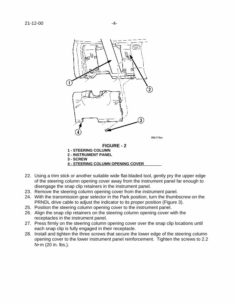
21-12-00 -4-
22. Using a trim stick or another suitable wide flat-bladed tool, gently pry the upper edgeof the steering column opening cover away from the instrument panel far enough todisengage the snap clip retainers in the instrument panel.
23. Remove the steering column opening cover from the instrument panel.24. With the transmission gear selector in the Park position, turn the thumbscrew on the
PRNDL drive cable to adjust the indicator to its proper position (Figure 3).25. Position the steering column opening cover to the instrument panel.26. Align the snap clip retainers on the steering column opening cover with the
receptacles in the instrument panel.27. Press firmly on the steering column opening cover over the snap clip locations until
each snap clip is fully engaged in their receptacle.28. Install and tighten the three screws that secure the lower edge of the steering column
opening cover to the lower instrument panel reinforcement. Tighten the screws to 2.2N•m (20 in. lbs.).
FIGURE - 21 - STEERING COLUMN2 - INSTRUMENT PANEL3 - SCREW4 - STEERING COLUMN OPENING COVER

-5- 21-12-00
POLICY: Reimbursable within the provisions of the warranty.
TIME ALLOWANCE:Labor Operation No: 21-75-26-93 ................................................................0.5 Hrs.
FAILURE CODE: P8 - New Part
FIGURE 31 - PRNDL LEVER2 - THUMB SCREW3 - CABLE RETAINER4 - PRNDL CABLE


2000 INDEX
GROUP 22WHEELS
BULLETIN SUBJECT MODELS TSB NO.
GROUP 22 - WHEELS
Spare Tire Winches 1999 - 2000 NS,GS 22-01-00
Wheel Cover Rattle - 149 Steel Wheels 2000 PL 22-02-00

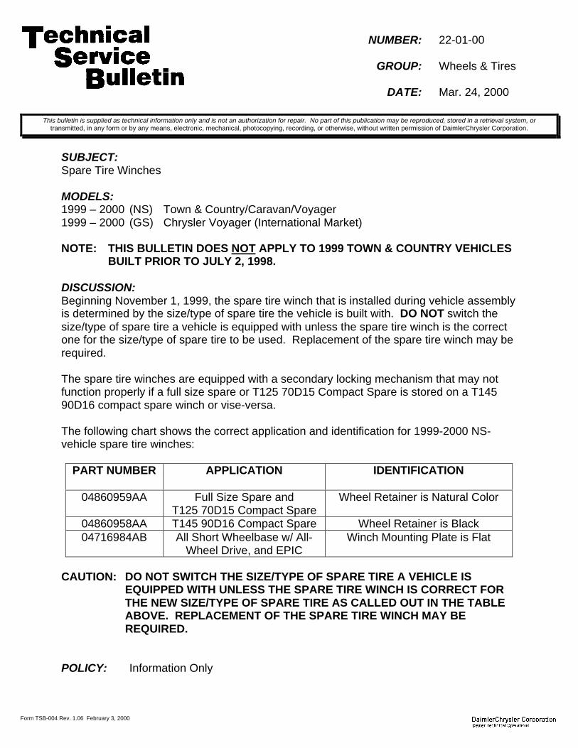
Form TSB-004 Rev. 1.06 February 3, 2000
NUMBER: 22-01-00
GROUP: Wheels & Tires
DATE: Mar. 24, 2000
SUBJECT:Spare Tire Winches
MODELS:1999 – 2000 (NS) Town & Country/Caravan/Voyager1999 – 2000 (GS) Chrysler Voyager (International Market)
NOTE: THIS BULLETIN DOES NOT APPLY TO 1999 TOWN & COUNTRY VEHICLESBUILT PRIOR TO JULY 2, 1998.
DISCUSSION:Beginning November 1, 1999, the spare tire winch that is installed during vehicle assemblyis determined by the size/type of spare tire the vehicle is built with. DO NOT switch thesize/type of spare tire a vehicle is equipped with unless the spare tire winch is the correctone for the size/type of spare tire to be used. Replacement of the spare tire winch may berequired.
The spare tire winches are equipped with a secondary locking mechanism that may notfunction properly if a full size spare or T125 70D15 Compact Spare is stored on a T14590D16 compact spare winch or vise-versa.
The following chart shows the correct application and identification for 1999-2000 NS-vehicle spare tire winches:
PART NUMBER APPLICATION IDENTIFICATION
04860959AA Full Size Spare andT125 70D15 Compact Spare
Wheel Retainer is Natural Color
04860958AA T145 90D16 Compact Spare Wheel Retainer is Black04716984AB All Short Wheelbase w/ All-
Wheel Drive, and EPICWinch Mounting Plate is Flat
CAUTION: DO NOT SWITCH THE SIZE/TYPE OF SPARE TIRE A VEHICLE ISEQUIPPED WITH UNLESS THE SPARE TIRE WINCH IS CORRECT FORTHE NEW SIZE/TYPE OF SPARE TIRE AS CALLED OUT IN THE TABLEABOVE. REPLACEMENT OF THE SPARE TIRE WINCH MAY BEREQUIRED.
POLICY: Information Only
This bulletin is supplied as technical information only and is not an authorization for repair. No part of this publication may be reproduced, stored in a retrieval system, ortransmitted, in any form or by any means, electronic, mechanical, photocopying, recording, or otherwise, without written permission of DaimlerChrysler Corporation.

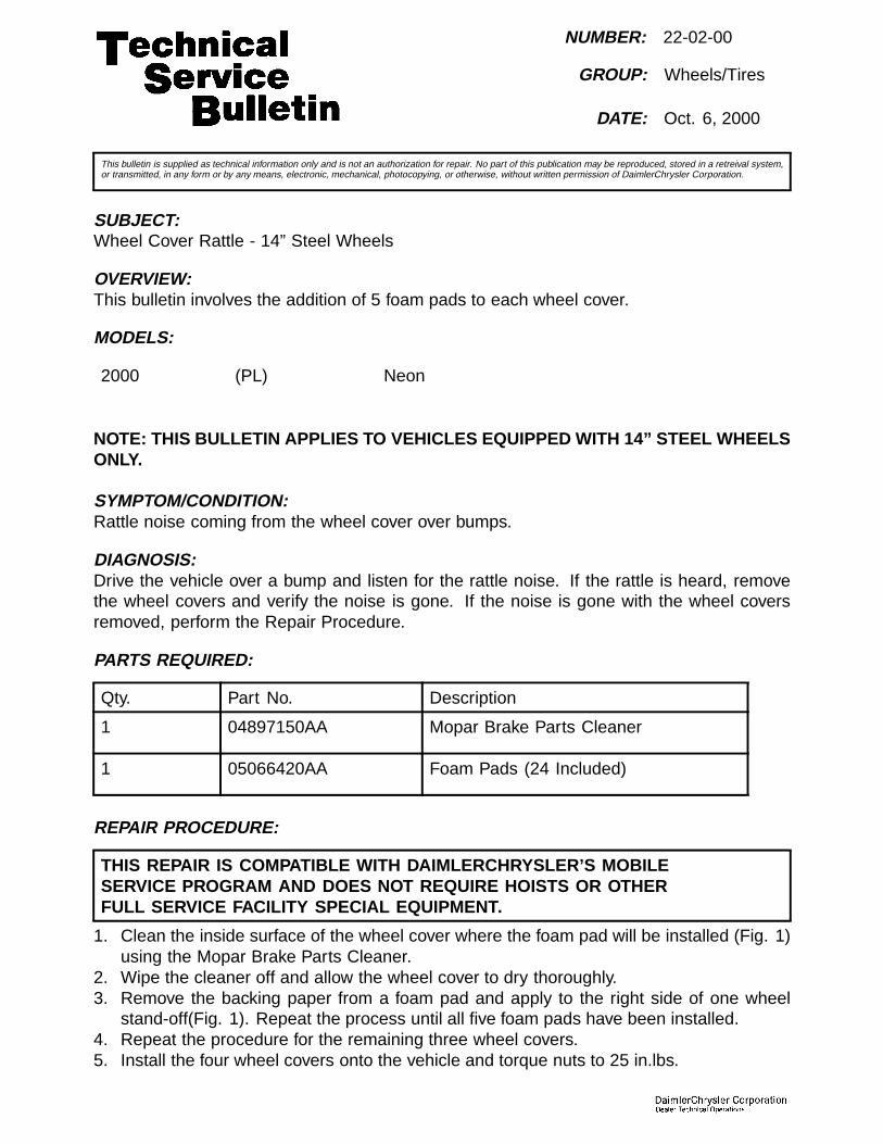
NUMBER: 22-02-00
GROUP: Wheels/Tires
DATE: Oct. 6, 2000
This bulletin is supplied as technical information only and is not an authorization for repair. No part of this publication may be reproduced, stored in a retreival system,or transmitted, in any form or by any means, electronic, mechanical, photocopying, or otherwise, without written permission of DaimlerChrysler Corporation.
SUBJECT:Wheel Cover Rattle - 14” Steel Wheels
OVERVIEW:This bulletin involves the addition of 5 foam pads to each wheel cover.
MODELS:
2000 (PL) Neon
NOTE: THIS BULLETIN APPLIES TO VEHICLES EQUIPPED WITH 14” STEEL WHEELSONLY.
SYMPTOM/CONDITION:Rattle noise coming from the wheel cover over bumps.
DIAGNOSIS:Drive the vehicle over a bump and listen for the rattle noise. If the rattle is heard, removethe wheel covers and verify the noise is gone. If the noise is gone with the wheel coversremoved, perform the Repair Procedure.
PARTS REQUIRED:
Qty. Part No. Description
1 04897150AA Mopar Brake Parts Cleaner
1 05066420AA Foam Pads (24 Included)
REPAIR PROCEDURE:
THIS REPAIR IS COMPATIBLE WITH DAIMLERCHRYSLER’S MOBILESERVICE PROGRAM AND DOES NOT REQUIRE HOISTS OR OTHERFULL SERVICE FACILITY SPECIAL EQUIPMENT.
1. Clean the inside surface of the wheel cover where the foam pad will be installed (Fig. 1)using the Mopar Brake Parts Cleaner.
2. Wipe the cleaner off and allow the wheel cover to dry thoroughly.3. Remove the backing paper from a foam pad and apply to the right side of one wheel
stand-off(Fig. 1). Repeat the process until all five foam pads have been installed.4. Repeat the procedure for the remaining three wheel covers.5. Install the four wheel covers onto the vehicle and torque nuts to 25 in.lbs.

22-02-00 -2-
Fig. 1 WHEEL COVER
1 - Foam Pads
2 - Wheel Cover Stand Off
POLICY:Reimbursible within the provisions of the warranty.
TIME ALLOWANCE:
Labor Operation No: 22-20-01-96 0.3 Hrs.
FAILURE CODE:
P8 New Part

2000 INDEX
GROUP 23BODY
BULLETIN SUBJECT MODELS TSB NO.
GROUP 23 - BODY
Convertible Top Damage 1997 - 2000 PR 23-01-00
Internal Emergency Trunk Release 1993 - 2000 LH, 1995 - 2000JA,PL 1996 - 2000 JX
23-02-00
Vehicle Identification Number (VIN) Plate Relo-cated
2000 - AN,BR/BE,DN 23-03-00
Door Trim Panel Cracking At Lower AttachingBosses
1998 - 1999 LH/LHS/300M 23-04-00
Driver’s Seat Back Cover Torn Or Door TrimPanel Damaged
2000 JX 23-05-00
Water Leak From Top Edge Of Right Or LeftFront Door
2000 PL 23-06-00
Wind Noise 1998 - 2000 LH,LHS/300M 23-07-00
Child Seat Tether Anchors 1988 - BB 1989 - AA,AB,AC,A-G,AH,AJ,AK,AL,AM,AN,AP,AS,BB,B2,B5,B7,XJ,1990 - AA,AB,AC,AG,AJ,AK,AL,AN,AP,AS,AY,BB,BD,B2,B7,XJ1991 - AA,AB,AC,AG,AJ,AN,AP,AS,AY,BB,BD,B2,B7,XJ1992 - AA,AB,AC,AG,AJ,AN,AP,AS,AY,BB,BD,B2,B3,B7,B8,XJ1993 - AA,AB,AC,AG,AJ,AN,AP,AS,AY,BD,B3,B7,B8,B9,LH,XJ,ZJ1994 - AA,AB,AG,AP,AS,BD,BR/BE,B3,B7,B8,B9,LH,XJ,ZJ1995 - AA,AB,AN,AS,BR/BE,B3,B7,B8,FJ,JA,LH,PL,XJ,ZJ1996 - AB,AN,BR/BE,FJ,JA,LH,NS,PL,SR,XJ,ZJ1997 - AB,AN,BR/BE,FJ,JA,LH,NS,PL,PR,SR,XJ,ZJ1998 - AB,AN,BR/BE,DN,FJ,JA,LH,NS,PL,PR,SR,XJ,ZJ1999 - AB,AN,BR/BE,DN,FJ,JA,LH,NS,PL,PR,SR,WJ,XJ2000 - AB,AN,BR/BE,DN,MNS,PL,WJ,XJ 2001 - BR/BE
23-08-00 Rev. A

BULLETIN SUBJECT MODELS TSB NO.
Side/Rear Cargo Door(s) Opens Past The Nor-mal 90 Degree Opening
1998 - 2000 AB 23-09-00
Window Regulator Sticks At Top Of Travel 1999 - 2000 WJ 23-10-00
Roof Panel Wavy Or Has Depressions 1996 - 2000 NS,GS 23-11-00 Rev. A
Driver’s Side Front Seat Belt Latch May InterfereWith Driver’s Hip
2000 - JX 23-12-00
Front Seat Cushion/Cover Loose 2000 AN 23-13-00
Cargo Net Installation Instructions 2001 PT 23-14-00
Sliding Door Will Not Open And/Or Close/Latch 1998 - 2000 AB 23-15-00
Buzz/Hum From Left/Right Front Door Speaker 2001 PT 23-16-00
Cargo Cover Shade Bracket Breaks 1999 - 2000 WJ 23-17-00
Hardtop Roof Sag 1999 - 2000 TJ 23-18-00
Instrument Panel Creak 1994 - 2001 BR/BE 23-19-00
Body Mounted Door Opening Weatherstrip Loose 1998 - 2000 LH/LHS/300M 23-20-00
Front Seat Binds or Sticks When Adjusting TheSeat Fore And Aft (Manual Seats).
2000 - WJ 23-21-00
B-Pillar And C-Pillar Applique On Doors Have ABrown Haze Or Appear Discolored
2001 - PT 23-22-00
Ignition Key Will Not Turn And/Or Cannot Be Re-moved
1997 - 2000 - NS 23-23-00
9B9 Pillar Front Door Edge Seal Loose or Missing 2000 - LH,LHS,300M 23-24-00
Paint Fogging/Whitening 1996 - 2000 JX 1995 - 2000 PL2001 - PT 1997 - 2001 BR
23-25-00
Unable To Release Rear Seat Floor Latch (Leftand/or Right) To Dump Seat Forward
2001 PT 23-26-00
This Bulletin Involves Repositioning And Lubricat-ing The Power Seat Track-Locating Pin
2000 - AN,DN 23-27-00
Passenger Compartment Floor/Carpet Wet 1996 - 2000 JX 23-28-00
Rear Door Trim Panel Loose At Upper Rear Cor-ner
1998 - 2001 LH/LHS/300M 23-29-00
Front Seat Belts May Be Slow To Retract 1999 - 2000 WJ 23-30-00
Rattle/Chuck In The Second Row Seat WhenSeat Is In Upright Position
1998 - 2000 DN 23-31-00
Quad Seat And 50/50 Rear Bench Seat Rattle OrGroan Sound And/Or Latch Effort
2001 - RS,RG 23-32-00 Rev. A
Sounds Associated With Power Sliding Door Op-eration
2001 - RS,RG 23-33-00
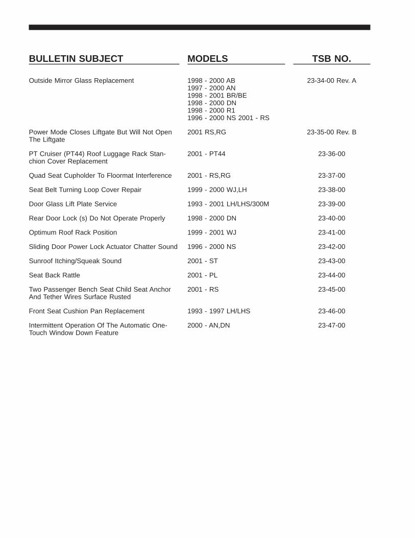
BULLETIN SUBJECT MODELS TSB NO.
Outside Mirror Glass Replacement 1998 - 2000 AB1997 - 2000 AN1998 - 2001 BR/BE1998 - 2000 DN1998 - 2000 R11996 - 2000 NS 2001 - RS
23-34-00 Rev. A
Power Mode Closes Liftgate But Will Not OpenThe Liftgate
2001 RS,RG 23-35-00 Rev. B
PT Cruiser (PT44) Roof Luggage Rack Stan-chion Cover Replacement
2001 - PT44 23-36-00
Quad Seat Cupholder To Floormat Interference 2001 - RS,RG 23-37-00
Seat Belt Turning Loop Cover Repair 1999 - 2000 WJ,LH 23-38-00
Door Glass Lift Plate Service 1993 - 2001 LH/LHS/300M 23-39-00
Rear Door Lock (s) Do Not Operate Properly 1998 - 2000 DN 23-40-00
Optimum Roof Rack Position 1999 - 2001 WJ 23-41-00
Sliding Door Power Lock Actuator Chatter Sound 1996 - 2000 NS 23-42-00
Sunroof Itching/Squeak Sound 2001 - ST 23-43-00
Seat Back Rattle 2001 - PL 23-44-00
Two Passenger Bench Seat Child Seat AnchorAnd Tether Wires Surface Rusted
2001 - RS 23-45-00
Front Seat Cushion Pan Replacement 1993 - 1997 LH/LHS 23-46-00
Intermittent Operation Of The Automatic One-Touch Window Down Feature
2000 - AN,DN 23-47-00


Form TSB-004 Rev. 1.05
NUMBER: 23-01-00
GROUP: Body
DATE: Jan. 21, 2000
SUBJECT:Convertible Top Damage
MODELS:1997 - 2000 (PR) Prowler
DISCUSSION:The convertible top cover may be damaged if the procedure in the Owner Manual to raisethe top from its stored position to the in use position is not followed. The damaged areawill be an abraded/scuffed area approximately 1 in. by 1/4 in., right of center and below thebacklight, Figure 1.
This abrasion/scuff is the result of failure to follow the correct procedure for putting the topin the in use position, as described in the Owner Manual. The abrasion/scuff results fromthe latch bracket contacting the top fabric and is not the result of a defect in material orworkmanship. The deck lid MUST be closed and latched BEFORE the rear portion of thetop is extended to its in use position.
If the vehicle owner desires to have the damage repaired, the top fabric is availableseparately, p/n 04897882AA. Replacement of the complete top assembly is not required.
POLICY: Information Only
This bulletin is supplied as technical information only and is not an authorization for repair. No part of this publication may be reproduced, stored in a retrieval system, ortransmitted, in any form or by any means, electronic, mechanical, photocopying, recording, or otherwise, without written permission of DaimlerChrysler Corporation.
1. ABRADED/SCUFFED AREA BELOW BACKLIGHT
FIGURE 1

Form TSB-004 Rev. 1.05
NUMBER: 23-02-00
GROUP: Body
DATE: Feb. 4, 2000
THIS BULLETIN SUPERSEDES TECHNICAL SERVICE BULLETIN 23-20-99 REV. ADATED AUGUST 13, 1999 WHICH SHOULD BE REMOVED FROM YOUR FILES. ALLREVISIONS ARE HIGHLIGHTED WITH **ASTERISKS** AND INCLUDE ADDITIONALMODELS AND PARTS INFORMATION.
SUBJECT:Internal Emergency Trunk Release
MODELS:1995 – 2000 (JA) Breeze/Cirrus/Stratus1996 - 2000 (JX) Sebring Convertible**1993 – 2000 (LH) Concorde/Intrepid/LHS/New Yorker/Vision/300M**1995 - 2000 (PL) Neon
NOTE: THIS BULLETIN IS PROVIDED TO IDENTIFY THE PARTS ANDPROCEDURES NECESSARY TO INSTALL AN INTERNAL EMERGENCYTRUNK RELEASE. RELEASE INSTALLATION EXPENSE IS SHARED BYDAIMLERCHRYSLER AND THE CUSTOMER. DAIMLERCHRYSLER WILLREIMBURSE YOU FOR THE LABOR ONLY. THE CUSTOMER ISRESPONSIBLE FOR THE PART EXPENSE. REFER TO WARRANTYBULLETIN D-99-20 FOR CLAIMING THE LABOR EXPENSE.
DISCUSSION:DaimlerChrysler Corporation is now offering internal emergency trunk releases for theselected vehicles listed above. Other applicable passenger vehicles will be announced assoon as the parts are available. The trunk releases are packaged in a kit containing allnecessary parts and a detailed instruction sheet.
PARTS REQUIRED:1 05016812AA Kit, Emergency Trunk Release, 1995 – 2000 JA**1 05016813AA Kit, Emergency Trunk Release, 1993 - 1997 LH**1 05016810AA Kit, Emergency Trunk Release, 1998 – 2000 LH1 05016809AA Kit, Emergency Trunk Release, 2000 PL W/Remote Entry1 05016811AA Kit, Emergency Trunk Release, 1994 - 1999 PL
2000 PL W/Manual Entry1 05016814AA Kit, Emergency Trunk Release, 1996 - 2000 JX
POLICY: Customer Satisfaction Announcement
TIME ALLOWANCE:Labor Operation No. 23-41-25-95 . . . . . . . . . . . . . . . . . . . . . . . . . . . . . . . . 1.2 Hrs.
FAILURE CODE: XX - Service Adjustment
This bulletin is supplied as technical information only and is not an authorization for repair. No part of this publication may be reproduced, stored in a retrieval system, ortransmitted, in any form or by any means, electronic, mechanical, photocopying, recording, or otherwise, without written permission of DaimlerChrysler Corporation.


Form TSB-004 Rev. 1.05
NUMBER: 23-03-00
GROUP: Body
DATE: Feb. 4, 2000
SUBJECT:Vehicle Identification Number (VIN) Plate Relocated
MODELS:2000 (AN) Dakota2000 (BR/BE) Ram Truck2000 (DN) Durango
DISCUSSION:The VIN plate on the subject model vehicles has been relocated from the instrument panelto the cowl bar. Due to the relocation of the VIN plate, the windshield frit (the frit is theblack-out band at the bottom of the windshield) required a change so that the VIN platecould be seen through the windshield. The view of the VIN plate may be blocked if a 1999or earlier windshield is installed on the vehicle.
NOTE: DO NOT INSTALL OR HAVE GLASS SUPPLIERS INSTALL 1999 OREARLIER WINDSHIELDS ON 2000 MODEL YEAR SUBJECT MODELVEHICLES. LIKEWISE, DO NOT INSTALL OR HAVE GLASS SUPPLIERSINSTALL 2000 OR LATER WINDSHIELDS ON EARLIER MODELS
If the VIN plate is not visible because the windshield frit blocks the view, the windshieldmust be replaced with the appropriate MOPAR Safe Guard glass.
POLICY: Information Only
This bulletin is supplied as technical information only and is not an authorization for repair. No part of this publication may be reproduced, stored in a retrieval system, ortransmitted, in any form or by any means, electronic, mechanical, photocopying, recording, or otherwise, without written permission of DaimlerChrysler Corporation.

Form TSB-003 Rev. 1.07
NUMBER: 23-04-00
GROUP: Body
DATE: Feb. 4, 2000
SUBJECT:Door Trim Panel Cracking At Lower Attaching Screw Bosses
OVERVIEW:This bulletin involves installing special clips to repair cracked door trim panels.
MODELS:1998 - 1999 (LH) Concorde/Intrepid/LHS/300M
SYMPTOM/CONDITION:When a door trim panel is removed for any reason the lower screw bosses may becomecracked (Figure 1). This is caused by an adverse reaction between the trim panel andfoam silencer pad around the attaching screw nut.
DIAGNOSIS:If any of the lower trim panel attaching bosses are cracked or pieces of plastic are missingfrom around the bosses, perform the Repair Procedure. The color keyed clips will coverthe cracked area on the door trim panel and prevent having to replace the panel.
PARTS REQUIRED:AR 0UB471D5AA Clip, Door Panel, QuartzAR 0UB471AZAA Clip, Door Panel, AgateAR 0UB47MF1AA Clip, Door Panel, Pearl Beige/NeutralAR 0UB471K5AA Clip, Door Panel, Camel
REPAIR PROCEDURE:
1. Install the colored keyed clips as necessary over any cracked trim panel attachingbosses (Figure 1).
This bulletin is supplied as technical information only and is not an authorization for repair. No part of this publication may be reproduced, stored in a retrieval system, ortransmitted, in any form or by any means, electronic, mechanical, photocopying, recording, or otherwise, without written permission of DaimlerChrysler Corporation.
THIS REPAIR IS COMPATIBLE WITH DAIMLERCHRYSLER'S MOBILE SERVICE PROGRAM ANDDOES NOT REQUIRE HOISTS OR OTHER FULL SERVICE FACILITY SPECIAL EQUIPMENT.
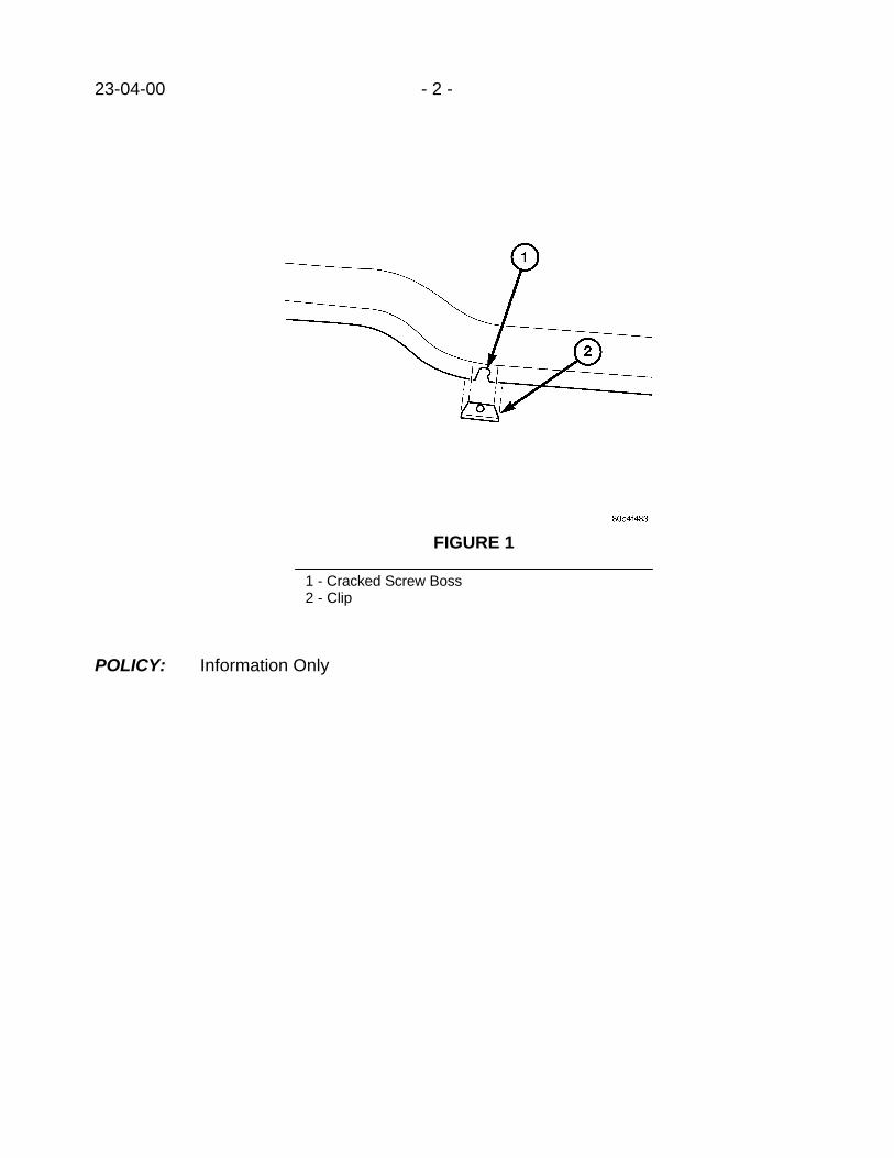
23-04-00 - 2 -
POLICY: Information Only
FIGURE 1
1 - Cracked Screw Boss2 - Clip

Form TSB-003 Rev. 1.07
NUMBER: 23-05-00
GROUP: Body
DATE: Feb. 11, 2000
SUBJECT:Driver’s Seat Back Cover Torn Or Door Trim Panel Damaged.
OVERVIEW:This bulletin involves replacing the driver’s side seat belt retractor if the seat back cover isdamaged due to an interference condition or adding a button to the belt webbing.
NOTE: THE BELT WEBBING BUTTON SHOULD BE ADDED TO ALL AFFECTEDIN STOCK VEHICLES OR VEHICLES IN FOR OTHER SERVICEREGARDLESS OF SEAT COVER DAMAGE.
MODELS:2000 (JX) Sebring Convertible
NOTE: THIS BULLETIN APPLIES TO VEHICLES BUILT BEFORE DECEMBER 10,1999 (MDH 1210XX).
SYMPTOM/CONDITION:The driver side seat back cover may have a cut or tear in the fabric on the outboard sideabout half way between the cushion and top of the seat. The owner may also describe acondition where the door will intermittently not close.
DIAGNOSIS:If the driver’s seat back has been cut or torn and the damage could be attributed to theseat belt tip being trapped between the seat back and the armrest on the door trim panel,the seat cover and the seat belt retractor must be replaced.
NOTE: THE SEAT BELT RETRACTOR MUST BE REPLACED IF THE SEAT BACKCOVER IS REPLACED FOR THIS CONDITION.
If the door is intermittently hard to close and there is evidence that the seat belt tip is beingtrapped between the seat back and the armrest on the door trim panel, but no damageexists, perform the Repair Procedure.
PARTS REQUIRED:AR(1) 0UD411AZAA Button, Male, Belt Webbing, AgateAR(1) 0UD461AZAA Button, Female, Belt webbing, AgateAR(1) 0UD411JKAA Button, Male, Belt Webbing, Silver FernAR(1) 0UD461JKAA Button, Female, Belt Webbing, Silver FernAR(1) 0UD411K5AA Button, Male, Belt Webbing, TanAR(1) 0UD461K5AA Button, Female, Belt Webbing, Tan
NOTE: ONE MALE AND ONE FEMALE PART ARE REQUIRED TO PERFORM ASINGLE REPAIR.
This bulletin is supplied as technical information only and is not an authorization for repair. No part of this publication may be reproduced, stored in a retrieval system, ortransmitted, in any form or by any means, electronic, mechanical, photocopying, recording, or otherwise, without written permission of DaimlerChrysler Corporation.

23-05-00 - 2-
REPAIR PROCEDURE:
1. Measure and mark the location 100 mm (4 inches) up from the existing seat beltwebbing button located on the outboard side just above the seat cushion (Figure 1).
2. Insert the belt webbing button through the belt at the new location.3. Snap the other half of the webbing button into place.4. Heat stake the webbing button into place using a soldering iron (Figure 2).5. The original webbing button may be removed by snapping it apart. The hole in the
webbing will close over time.
THIS REPAIR IS COMPATIBLE WITH DAIMLERCHRYSLER'S MOBILE SERVICE PROGRAM ANDDOES NOT REQUIRE HOISTS OR OTHER FULL SERVICE FACILITY SPECIAL EQUIPMENT.
FIGURE 1
1 - New Button 4” Higher Than Existing Button

- 3 - 23-05-00
POLICY: Reimbursable within the provisions of the warranty.
TIME ALLOWANCE:Labor Operation No: 23-13-03-93 ................................................................0.2 Hrs.
FAILURE CODE: P8 - New Part
FIGURE 2
1 - Heat Stake Button


Form TSB-003 Rev. 1.07
NUMBER: 23-06-00
GROUP: Body
DATE: Feb. 18, 2000
THIS BULLETIN SUPERSEDES TECHNICAL SERVICE BULLETIN 23-53-99, DATEDDEC. 17, 1999, WHICH SHOULD BE REMOVED FROM YOUR FILES AND NOTED INTHE 1999 TECHNICAL SERVICE BULLETIN MANUAL (PUBLICATION NO. 81-699-00004). ALL REVISIONS ARE HIGHLIGHTED WITH **ASTERISKS** AND NOWINCLUDES THE LEFT FRONT DOOR.
SUBJECT:**Water Leak From Top Edge Of Right Or Left Front Door**
OVERVIEW:This bulletin involves covering the step in the sheet metal with tape or a seam sealer.
MODELS:2000 (PL) Neon
SYMPTOM/CONDITION:**Water leaks from the top edge of the right and/or left front door into the passengercompartment. ** This leak is due to a step in the sheet metal laser welded joint seam(Figure 1).
This bulletin is supplied as technical information only and is not an authorization for repair. No part of this publication may be reproduced, stored in a retrieval system, ortransmitted, in any form or by any means, electronic, mechanical, photocopying, recording, or otherwise, without written permission of DaimlerChrysler Corporation.
INTERIOR TOP LEFT CORNER OF RIGHT FRONTDOOR SHOWN
1 - SHEET METAL LASER WELDED JOINT SEAM2 - TOP CORNER WINDOW MOLDING SHOWN
FIGURE 1

23-06-00 -2-
DIAGNOSIS:Inspect the right and left front door frame at the top laser welded joint seam. If one side ofthe joint is raised above the other, perform the Repair Procedure (Figure 1).
PARTS REQUIRED:AR NPN 3M ScotchCal Paint Protection Film #84701 Or EquivalentAR NPN Sure Check Clear Sealer (LSC) 5 oz Tube Or Equivalent
NOTE: THE 3M SCOTCHCAL PAINT PROTECTION FILM AND SURE CHECK CLEARSEALER CAN BE FOUND AT MOST LOCAL AUTOBODY SUPPLIERS. IFTHE SURE CHECK CLEAR SEALER IS NOT AVAILABLE IT CAN BEOBTAINED BY CALLING 1-800-265-0790.
REPAIR PROCEDURE:
1. **Open the front door(s). Measure the top laser welded joint seam on each door, if thestep is less than 1mm (0.039 in), perform Repair Procedure 1. If the step is more than1mm (0.039 in) perform the Repair Procedure 2. **
Repair Procedure 1 (Film) (Less Than 1mm (0.039 In.)1. Carefully pull the top of the window flag portion of the door trim panel outward to gain
full access to the frame at the top laser welded joint seam. It is not necessary toremove the door trim panel.
2. Clean the step area with isopropyl alcohol.3. Cut two 101 mm (4 in.) x 25 mm (1 in) pieces of the 3M ScotchCal Paint Protection
Film or equivalent. The two pieces of film will be put one on top of the other beforeattaching to the vehicle.
4. Remove the protective paper from one piece of the film cut in step 3.5. Place the piece of film directly over the other piece and use an applicator to completely
smooth out any air bubbles. It is important for the appearance that the two pieces belined up exactly and any air bubbles be removed.
6. Remove the protective paper from the joined pieces of film and beginning at the topedge, install over the step. Use a plastic spreader such as one used for applying bodyfillers to smooth out any air bubbles. Ensure the tape is firmly seated.
7. Using a razor blade trim the excess tape at the top of the door frame.8. Push the window flag portion of the door trim panel in until the clip is fully seated.9. Water test the vehicle to insure complete sealing.
Repair Procedure 2 (Sealer) (More Than 1mm (0.039 In.)1. Remove the door trim panel.2. Clean the step area with isopropyl alcohol (Figure 1).3. Tape off the area around the step leaving a 1/4 inch space around the seam step
(Figure 2).
THIS REPAIR IS COMPATIBLE WITH DAIMLERCHRYSLER'S MOBILE SERVICE PROGRAM ANDDOES NOT REQUIRE HOISTS OR OTHER FULL SERVICE FACILITY SPECIAL EQUIPMENT.
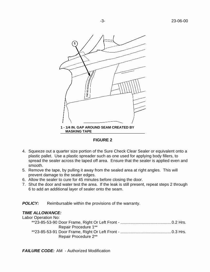
-3- 23-06-00
4. Squeeze out a quarter size portion of the Sure Check Clear Sealer or equivalent onto aplastic pallet. Use a plastic spreader such as one used for applying body fillers, tospread the sealer across the taped off area. Ensure that the sealer is applied even andsmooth.
5. Remove the tape, by pulling it away from the sealed area at right angles. This willprevent damage to the sealer edges.
6. Allow the sealer to cure for 45 minutes before closing the door.7. Shut the door and water test the area. If the leak is still present, repeat steps 2 through
6 to add an additional layer of sealer onto the seam.
POLICY: Reimbursable within the provisions of the warranty.
TIME ALLOWANCE:Labor Operation No:
**23-85-53-90 Door Frame, Right Or Left Front - ............................................0.2 Hrs. Repair Procedure 1**
**23-85-53-91 Door Frame, Right Or Left Front - ............................................0.3 Hrs. Repair Procedure 2**
FAILURE CODE: AM - Authorized Modification
1 - 1/4 IN. GAP AROUND SEAM CREATED BY MASKING TAPE
FIGURE 2


Form TSB-003 Rev. 1.07
NUMBER: 23-07-00
GROUP: Body
DATE: Feb. 25, 2000
THIS BULLETIN SUPERSEDES TECHNICAL SERVICE BULLETIN 23-30-98 DATEDJULY 17, 1998 WHICH SHOULD BE NOTED IN THE 1998 TECHNICAL SERVICEBULLETIN MANUAL (PUBLICATION NO. 81-699-99003). ALL REVISIONS AREHIGHLIGHTED WITH **ASTERISKS** AND INCLUDE ADDITIONAL MODELS, PARTS,AND PROCEDURES.
SUBJECT:Wind Noise
OVERVIEW:This bulletin involves checking and/or sealing the A-pillar cavity, front door body mountedweatherstrip, door flag speakers, **sunroof** and windshield wipers.
MODELS:1998 - **2000** (LH) Concorde/Intrepid/LHS/300M
SYMPTOM/CONDITION:Wind noise heard from the **sunroof** or B-pillar forward in the vehicle while driving athighway speeds above 55 mph or at lower speeds into a headwind.
DIAGNOSIS:Perform the wind noise diagnostic procedure on page 23-32 of the 2000Concorde/Intrepid/LHS/300M Service Manual (Publication No. 81-270-0040). If thisprocedure and related repairs do not resolve the condition, perform the Repair Procedure.
PARTS REQUIRED:AR(1) 04780608AB Weatherstrip, Right Front Body Mounted, 1998-1999 M. Y.AR(1) 04780609AB Weatherstrip, Left Front Body Mounted, 1998-1999 M. Y.**AR(1) 0TE72HD5AD Weatherstrip, Right Front Body Mounted, 2000 M. Y., Quartz****AR(1) 0TE72LAZAD Weatherstrip, Right Front Body Mounted, 2000 M. Y., Agate****AR(1) 0TE72MF1AD Weatherstrip, Right Front Body Mounted, 2000 M. Y., Neutral****AR(1) 0TE72RK5AD Weatherstrip, Right Front Body Mounted, 2000 M. Y., Camel****AR(1) 0TE73HD5AD Weatherstrip, Left Front Body Mounted, 2000 M. Y., Quartz****AR(1) 0TE73LAZAD Weatherstrip, Left Front Body Mounted, 2000 M. Y, Agate****AR(1) 0TE73MF1AD Weatherstrip, Left Front Body Mounted, 2000 M. Y., Neutral****AR(1) 0TE73RK5AD Weatherstrip, Left Front Body Mounted, 2000 M. Y., Camel**
REPAIR PROCEDURE:
Procedure A1. Remove the instrument panel end cap.2. Remove the A-pillar trim.3. Apply a thumb grade sealer, Mopar Butyl Tape, p/n 04076274, or equivalent to
completely close the hole at the base of the A-pillar (Figure 1).
This bulletin is supplied as technical information only and is not an authorization for repair. No part of this publication may be reproduced, stored in a retrieval system, ortransmitted, in any form or by any means, electronic, mechanical, photocopying, recording, or otherwise, without written permission of DaimlerChrysler Corporation.
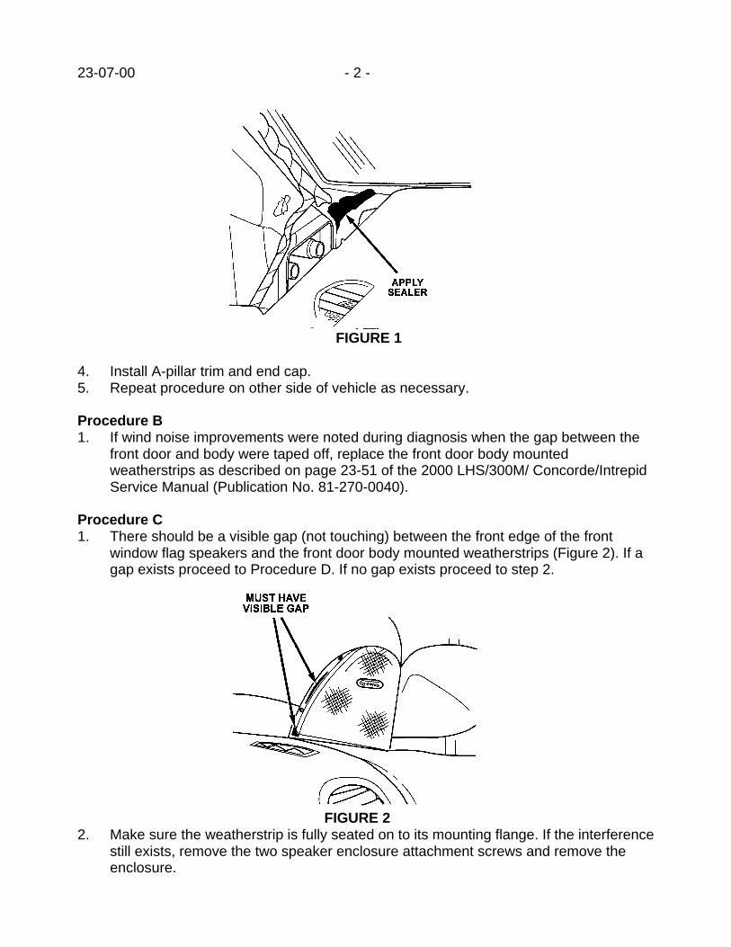
23-07-00 - 2 -
FIGURE 1
4. Install A-pillar trim and end cap.5. Repeat procedure on other side of vehicle as necessary.
Procedure B1. If wind noise improvements were noted during diagnosis when the gap between the
front door and body were taped off, replace the front door body mountedweatherstrips as described on page 23-51 of the 2000 LHS/300M/ Concorde/IntrepidService Manual (Publication No. 81-270-0040).
Procedure C1. There should be a visible gap (not touching) between the front edge of the front
window flag speakers and the front door body mounted weatherstrips (Figure 2). If agap exists proceed to Procedure D. If no gap exists proceed to step 2.
FIGURE 22. Make sure the weatherstrip is fully seated on to its mounting flange. If the interference
still exists, remove the two speaker enclosure attachment screws and remove theenclosure.

- 3 - 23-07-00
3. Remove the two speaker attaching screws and remove the speaker.4. Loosen the two screws that attach the speaker mounting plate to the door. Reposition
the plate rearward and reinstall the speaker and enclosure.5. If the interference still exists, remove the speaker mounting plate and slot the
mounting holes 1-2 mm (1/16 in.) in the fore-aft direction to provide additionaladjustment. Reassemble plate, speaker, and enclosure.
6. Repeat procedure on other side of vehicle as necessary.
Procedure D1. Check the position of the windshield wiper assemblies in the park (off) position. If the
wipers are above the positioning (“tic”) marks on the windshield adjust as necessary(Figure 3).
FIGURE 3**Procedure E1. Check the gap around the perimeter of the sunroof between the seal and the roof
aperture. The seal should make contact all around and there should be no gap.Dragging a business card (~0.3mm thick) around the perimeter should be provideuniform resistance.
2. If there is a gap or low drag resistance at the front, or rear, edge of the glass, loosenthe four attaching screws so that glass can be adjusted (Figure 4). Reposition theglass panel so that it is evenly spaced front to back and again recheck the drag onthe business card. Readjust until the front to back gap is uniform.
3. Tighten the four attaching screws to 5.5 Nm (50 in. lbs.).4. Cycle the sun roof and check the glass flushness.

23-07-00 - 4 -
POLICY: Reimbursable within the provisions of the warranty.
TIME ALLOWANCE:Labor Operation No: 25-50-00-99 Repair Procedure A 0.2 Hrs.
Both Sides
23-51-10-93 Repair Procedure B 0.2 Hrs.Both Sides
23-10-00-91 Repair Procedure C 0.2 Hrs.One Side
23-43-35-95 Repair Procedure D 0.2 Hrs.One or Both Sides
23-30-65-91 Repair Procedure E 0.2 Hrs.
FAILURE CODE: XX - Service Adjustment
FIGURE 4
1 - ATTACHING SCREW

Form TSB-003 Rev. 1.08 February 3, 2000
NUMBER: 23-08-00 Rev. A
GROUP: Body
DATE: Jul. 7, 2000
THIS BULLETIN SUPERSEDES TECHNICAL SERVICE BULLETIN 23-08-00 DATEDMARCH 3, 2000, WHICH SHOULD BE REMOVED FROM YOUR FILES. ALLREVISIONS ARE HIGHLIGHTED WITH **ASTERISKS** AND INCLUDE VEHICLEAPPLICATION CORRECTIONS/ALLOWANCES.
SUBJECT:Child Seat Tether Anchors
MODELS:1989 - 1995 (AA) Spirit/Acclaim/LeBaron Sedan1989 - 2000 (AB) Ram Van/Wagon1989 - 1993 (AC) Dynasty/New Yorker/New Yorker Salon1989 - 1994 (AG) Daytona1989 (AH) Lancer/Lebaron GTS1989 - 1993 (AJ) LeBaron Coupe1989 - 1990 (AK) Aries/Reliant1989 - 1990 (AL) Horizon/Omni1989 (AM) Diplomat/Gran Fury/New Yorker Fifth Avenue1989 - 2000 (AN) Dakota1989 - 1994 (AP) Shadow/Sundance1989 - 1995 (AS) Town & Country/Caravan/Voyager1990 - 1993 (AY) Imperial/New Yorker Fifth Avenue1988 - 1992 (BB) Monaco/Premier1990 - 1994 (BD) Laser/Talon1994 - **2001** (BR/BE) Ram Truck1989 - 1992 (B2) Colt/Summit1992 - 1995 (B3) Colt Vista1989 (B5) Conquest1989 - 1995 (B7) Stealth (2000 GTX Dodge/Eagle, Canada)1992 - 1995 (B8) Colt Vista Wagon/Summit Wagon1993 - 1994 (B9) Colt/Summit1998 - 2000 (DN) Durango1995 - 1999 (FJ) Sebring/Avenger/Talon1995 - 1999 (JA) Cirrus/Stratus/Breeze1993 - 1999 (LH) Concorde/Intrepid/Vision/LHS/New Yorker/300M1996 - 2000 (NS) Town & Country/Caravan/Voyager1995 - 2000 (PL) Neon1997 - 1999 (PR) Prowler1996 - 1999 (SR) Viper/Viper GTS1999 - 2000 (WJ) Grand Cherokee1989 - 1999 (XJ) Cherokee/Wagoneer1993 - 1998 (ZJ) Grand Cherokee/Grand Wagoneer
This bulletin is supplied as technical information only and is not an authorization for repair. No part of this publication may be reproduced, stored in a retrieval system, ortransmitted, in any form or by any means, electronic, mechanical, photocopying, recording, or otherwise, without written permission of DaimlerChrysler Corporation.

23-08-00 Rev. A 2 -
NOTE: THIS BULLETIN IS PROVIDED TO IDENTIFY THE PARTS AND LABOROPERATION NUMBERS NECESSARY TO INSTALL A CHILD SEAT TETHERANCHOR. DAIMLERCHRYSLER WILL REIMBURSE YOU FOR THEANCHORS AND LABOR TO INSTALL THEM. THIS IS BEING DONE IN THEINTEREST OF CUSTOMER SATISFACTION. REFER TO GLOBALWARRANTY ADMINISTRATION BULLETIN #D-99-23 FOR COMPLETEREIMBURSEMENT INSTRUCTIONS.
DISCUSSIONUser-ready child restraint tether strap anchors will be provided in passenger cars in the2000 Model Year, and in light trucks in the 2001 Model Year. Tether straps improve theperformance of child restraints in collisions. Because of the publicity that hasaccompanied the “Fit for a Kid” Program, owners of earlier products are expected toapproach dealers for the free provision and installation of the anchor hardware.DaimlerChrysler Corporation is offering child seat tether anchors for the selected vehicleslisted above. Each tether anchor is packaged in a kit containing all necessary parts and adetailed instruction sheet.
PARTS REQUIRED:
BODY MODEL YEAR CENTER OUTBOARD
AA LeBaron Sedan/Spirit/Acclaim 89-95 04519071AB 04519071ABAB Ram Wagon 89-00 04358469AB 04358469AB
AC New Yorker/ Landau/Dynasty 89-93 04519073AB 04519072ABAG Daytona 89-90
91-94
NA
NA
05003422AB
04519074AB
AH Lancer/LeBaron GTS 89 04519076AB 05003422ABAJ LeBaron Coupe 89-93 04519077AB 04519077ABAK Aries/Reliant 89-90 04519077AB 04519077ABAL Horizon/Omni 89-90 04519081AB 04519080AB
AM Diplomat/Gran Fury/N.Y.FifthAvenue
89 04519077AB 04519077AB
AN Dakota
AN84: 4-Door
AN31: Extended Cab
AN61 : Standard Cab
88-99
00
00
00
05014765AA
05016573AA
05016572AA
05017683AA
05014765AA
05016573AA
05016572AA
05017683AA
AP Shadow/Sundance 89-94 04519292AB 04519292AB
AS Town & Country/Caravan/Voyager 89-95 05017529AA 05017529AA
AY Imperial/New Yorker Fifth Avenue 90-93 04519071AB 04519071AB
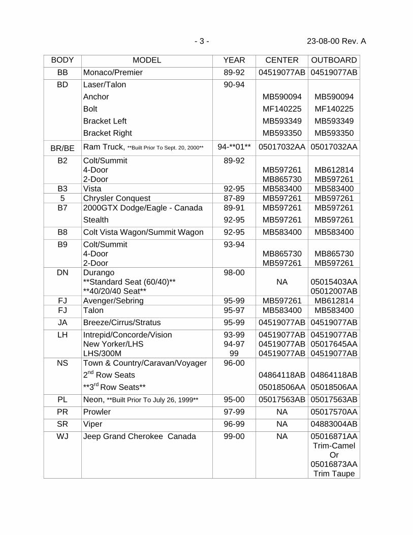
- 3 - 23-08-00 Rev. A
BODY MODEL YEAR CENTER OUTBOARD
BB Monaco/Premier 89-92 04519077AB 04519077AB
BD Laser/Talon
Anchor
Bolt
Bracket Left
Bracket Right
90-94
MB590094
MF140225
MB593349
MB593350
MB590094
MF140225
MB593349
MB593350
BR/BE Ram Truck, **Built Prior To Sept. 20, 2000** 94-**01** 05017032AA 05017032AA
B2 Colt/Summit4-Door2-Door
89-92MB597261MB865730
MB612814MB597261
B3 Vista 92-95 MB583400 MB5834005 Chrysler Conquest 87-89 MB597261 MB597261
B7 2000GTX Dodge/Eagle - Canada
Stealth
89-91
92-95
MB597261
MB597261
MB597261
MB597261
B8 Colt Vista Wagon/Summit Wagon 92-95 MB583400 MB583400
B9 Colt/Summit4-Door2-Door
93-94MB865730MB597261
MB865730MB597261
DN Durango**Standard Seat (60/40)****40/20/40 Seat**
98-00NA 05015403AA
05012007ABFJ Avenger/Sebring 95-99 MB597261 MB612814FJ Talon 95-97 MB583400 MB583400
JA Breeze/Cirrus/Stratus 95-99 04519077AB 04519077AB
LH Intrepid/Concorde/VisionNew Yorker/LHSLHS/300M
93-9994-97
99
04519077AB04519077AB04519077AB
04519077AB05017645AA04519077AB
NS Town & Country/Caravan/Voyager
2nd Row Seats
**3rd Row Seats**
96-00
04864118AB
05018506AA
04864118AB
05018506AA
PL Neon, **Built Prior To July 26, 1999** 95-00 05017563AB 05017563AB
PR Prowler 97-99 NA 05017570AA
SR Viper 96-99 NA 04883004AB
WJ Jeep Grand Cherokee Canada 99-00 NA 05016871AATrim-Camel
Or05016873AATrim Taupe

23-08-00 Rev. A - 4 -
BODY MODEL YEAR CENTER OUTBOARD
WJ Jeep Grand Cherokee US 99-00 NA 05016869AATrim Camel
Or05016870AATrim Taupe
XJ Jeep Cherokee 89-99 NA 05003422AB
ZJ Jeep Grand Cherokee/Grand
Wagoneer
93-98 04728952AB NA
POLICY: Customer Satisfaction
Labor Op. Number Description Vehicle App./YearAllowance
23-13-12-90 Anchor, Child Seat 1989-1995 (AA) 0.2Tether – Install One 1989-1994 (AG, AP)
1989 (AH, AM)1989-1993 (AJ)1989-1990 (AK, AL)1988-1992 (BB)1998-2000 (DN)1995-1999 (JA)1995-2000 (PL)1996-1999 (SR)1989-1993 (AC) 0.31990-1993 (AY)1995-1999 (FJ)1993-1999 (LH)1989-1995 (AS) 0.41996-2000 (NS)1989-1999(XJ)1993-1998 (ZJ)1989-2000 (AB) 0.51989-1995 (B7) A/T1990-1994 (BD)1989-1992 (B2)1994-**2001** (BR, BE)1992-1995 (B3, B8)1989 (B5)1993-1994 (B9)1999-2000 (PR)1999-2000 (PR, WJ)

- 5 - 23-08-00 Rev. A
23-13-12-91 Anchor, Child Seat 1998-2000 (DN) 0.2Tether – Install Two 1989-1995 (AA) 0.3
1989-1994 (AG, AP)1989 (AH, AM)1989-1993 (AJ)1989-1990 (AK, AL)1988-1992 (BB)1995-1999 (JA)1995-2000 (PL)1989-1993 (AC) 0.41990-1993 (AY)1993-1999 (LH)1989-1995 (AS) 0.51996-2000 (NS)1989-1999 (XJ) 0.61989-2000 (AB) 0.71989-2000 (AN) 1.01999-2000 (WJ) A/T
23-13-12-92 Anchor, Child Seat 1989-1995 (AA) 0.4Tether – Install Three 1989 (AH, AM)
1989-1993 (AJ)1989-1990 (AK, AL)1989-1994 (AP)1988-1992 (BB)1995-1999 (JA)1995-2000 (PL)1989-1993 (AC) 0.51990-1993 (AY)1993-1999 (LH)1996-2000 (NS) 0.61989-2000 (AN) 1.2
**23-13-12-93 Anchor, Child Seat 1996-2000 NS 0.3Tether - Install One -Third Seat**
**23-13-12-94 Anchor, Child Seat 1996-2000 (NS) 0.4Tether - Install Two OrThree - Third Seat**
Failure Code: CG – Customer Satisfaction


Form TSB-003 Rev. 1.07
NUMBER: 23-09-00
GROUP: Body
DATE: Mar. 3, 2000
SUBJECT:Side/Rear Cargo Door(s) Opens Past The Normal 90 Degree Opening
OVERVIEW:This bulletin involves installing a new check arm pin and bumper and in some cases a newcheck arm.
MODELS:1998 - 2000 (AB) Ram Van
SYMPTOM/CONDITION:The side and/or rear cargo door(s) may have the door check arm retaining pin bentallowing the door to open past the normal 90 degree opening or a metal-to-metal contactnoise may be heard when the door is opened fully. In severe cases, the door may open toa point where the door may make contact to the corner panel.
DIAGNOSIS:Check the side/rear cargo door to verify if the door opens past the normal 90 degreeopening and/or if a metal-to-metal contact noise can be heard when the door is fully open.If the door opens past the normal 90 degree opening and/or if a metal-to-metal contactnoise can be heard when the door is fully open, perform the Repair Procedure.
NOTE: PERFORM THE DIAGNOSIS ON ALL SIDE/REAR CARGO DOORS.
PARTS REQUIRED:AR (4) 55347338AD Bumper, Check Arm StopAR (4) 06035950AA Pin, Check ArmAR (2) 55346730AC Arm, Check, Right SideAR (2) 55346731AC Arm, Check, Left Side
REPAIR PROCEDURE:
1. Remove and replace the cargo door check arm pin and stop bumper on any door thatopens past the normal 90 degree opening and/or if a metal-to-metal contact noise canbe heard when the door is fully open. Refer to the 2000 Ram Van/Wagon ServiceManual (Publication No. 81-370-0007), page 23-54, “Rear Cargo Door Restraint.”
NOTE: REPLACE THE CHECK ARM IF THE CHECK ARM IS BENT OR SHOWSANY SIGNS OF DAMAGE.
This bulletin is supplied as technical information only and is not an authorization for repair. No part of this publication may be reproduced, stored in a retrieval system, ortransmitted, in any form or by any means, electronic, mechanical, photocopying, recording, or otherwise, without written permission of DaimlerChrysler Corporation.
THIS REPAIR IS COMPATIBLE WITH DAIMLERCHRYSLER'S MOBILE SERVICE PROGRAM ANDDOES NOT REQUIRE HOISTS OR OTHER FULL SERVICE FACILITY SPECIAL EQUIPMENT.

23-09-00 -2-
POLICY: Reimbursable within the provisions of the warranty.
TIME ALLOWANCE:Labor Operation No:
23-40-26-93 Replace Side Cargo Door Check Arm Pin And BumperAnd If Necessary, Replace the Check Arm, Left Side ................0.3 Hrs.
23-40-26-94 Replace Side Cargo Door Check Arm Pin And BumperAnd If Necessary, Replace the Check Arm, Right Side..............0.3 Hrs.
23-40-26-95 Replace Rear Cargo Door Check Arm Pin And BumperAnd If Necessary, Replace the Check Arm, Left Side ................0.3 Hrs.
23-40-26-96 Replace Rear Cargo Door Check Arm Pin And BumperAnd If Necessary, Replace the Check Arm, Right Side..............0.3 Hrs.
23-40-26-97 Replace Rear Single Cargo Door Check Arm Pin AndBumper And If Necessary, Replace the Check Arm...................0.3 Hrs.
FAILURE CODE: P8 - New Part

Form TSB-003 Rev. 1.06
NUMBER: 23-10-00
GROUP: Electrical
DATE: March 3, 2000
THIS BULLETIN SUPERSEDES TECHNICAL SERVICE BULLETIN NUMBER 23-37-99,DATED SEPTEMBER 24, 1999, WHICH SHOULD BE REMOVED FROM YOUR FILES.THE CHANGES INVOLVING REPLACING OF THE WINDOW REGULATOR, INADDITION TO ELONGATING THE REGULATOR MOUNTING HOLES, AREHIGHLIGHTED WITH ASTERISKS.
SUBJECT:Window Regulator Sticks At Top of Travel
OVERVIEW:**This bulletin involves enlarging the window regulator attaching holes in the door paneland replacing the window regulator. **
MODELS:1999 - 2000 (WJ) Grand Cherokee
SYMPTOM/CONDITION:A front window may be inoperative, stuck in the up position.
DIAGNOSIS:If the condition is present and no other electrical problems are found, perform the RepairProcedure.
**PARTS REQUIRED****AR 55076466AD Regulator right****AR 55076467AD Regulator left**
REPAIR PROCEDURE:
1. Remove the door trim panel.2. **Remove the window retaining clips to the lift plate.**3. **Separate the glass from the lift plate, slide it to the top of the travel and tape the
glass to the doorframe.**4. **Remove the regulator attaching bolts (See Figure 1) and the three-window motor
attaching bolts. **5. **Disconnect the wire harness from the regulator.**6. **Remove the window regulator **.
**NOTE: VEHICLES BUILT AFTER SEPTEMBER 28, 1999, (MDH 0928XX), DONOT REQUIRE ELONGATING THE REGULATOR ATTACHING HOLES.PROCEED TO STEP 10 ON THESE VEHICLES. **
This bulletin is supplied as technical information only and is not an authorization for repair. No part of this publication may be reproduced, stored in a retrieval system, ortransmitted, in any form or by any means, electronic, mechanical, photocopying, recording, or otherwise, without written permission of DaimlerChrysler Corporation.
THIS REPAIR IS COMPATIBLE WITH DAIMLERCHRYSLER'S MOBILE SERVICE PROGRAM ANDDOES NOT REQUIRE HOISTS OR OTHER FULL SERVICE FACILITY SPECIAL EQUIPMENT.

23-10-00 -2-
7. Mark the centerline of the top three regulator holes at the top.Measure 5 mm (3/16 in.) straight up from the top of the hole and make another markat that location.
8. Using an 8 mm (5/16 in.) grinding stone or a rat tailed file, elongate the holes upwardto the marks made earlier at the three bolt locations. This will allow the regulator tobe moved upward 5 mm (1/4 IN.).
9. Coat the holes with a corrosion resistant primer and allow the primer to dry.10. **Install the new regulator and attaching bolts applying upward pressure to assure
that the regulator seats in the higher location. Tighten the bolts to 9 Nm (80 in. lbs.).**
11. Install the glass on to the lift plate and install the retaining clips.12. Install the door trim panel.
POLICY: Reimbursable within the provisions of the warranty.
TIME ALLOWANCE:Labor Operation No: 23-34-11-98/99 ............................................................0.9 Hrs.
FAILURE CODE: P8 - New Part
1 - REGULATOR BOLTS2 - WINDOW MOTOR NUTS3 - ELONGATE THESE HOLES
FIGURE 1

NUMBER: 23-11-00 Rev. A
GROUP: Body
DATE: Apr. 7, 2000
THIS BULLETIN SUPERSEDES TECHNICAL SERVICE BULLETIN 23-28-96, DATEDMAY 3, 1996, WHICH SHOULD BE REMOVED FROM YOUR FILES AND NOTED INTHE 1996 TECHNICAL SERVICE BULLETIN MANUAL (PUBLICATION NO. 81-699-97010). THIS BULLETIN ALSO SUPERSEDES TECHNICAL SERVICE BULLETIN 23-11-00, DATED MAR 24, 2000, WHICH SHOULD BE REMOVED FROM YOUR FILES.ALL REVISIONS ARE HIGHLIGHTED WITH **ASTERISKS** AND INCLUDE AREVISED LABOR OPERATION NUMBER.
SUBJECT:Roof Panel Wavy Or Has Depressions
OVERVIEW:This bulletin involves applying heat to the roof panel to remove depression(s).This Repair Procedure is not intended to be used to correct any type ofimpact/damage caused dents.
MODELS:1996 – 2000 (NS) Town & Country/Caravan/Voyager1996 – 2000 (GS) Chrysler Voyager (International Market)
SYMPTOM/CONDITION:The roof panel surface exhibits waviness or depression(s) near the front of thecharacter features or skid strip for roof rack equipped vehicles. Typically theshape of the depression or waviness will be elliptical or along a line across thevehicle. The depression(s) will go away on their own as the vehicle is exposed tohigher ambient temperatures and sun load.
DIAGNOSIS:While standing in front of the vehicle, visually inspect the roof panel, if anydepression(s) or waviness is seen in one or both areas shown in Figure 1, performthe following Repair Procedure only if the customer is unwilling to wait for higherambient temperatures to remove the depression(s).
EQUIPMENT REQUIRED:Heat Gun such as Pentastar Service Equipment (PSE) W-PH1200
REPAIR PROCEDURE:
1. Refer to Figure 1 and apply heat to of the areas indicated for one depression at atime. The heat gun should be set for approximately 500o F (260o C). Keep the gunmoving constantly to avoid scorching the paint. Avoid applying heat directly to theroof rack skid strips if so equipped.
This bulletin is supplied as technical information only and is not an authorization for repair. No part of this publication may be reproduced, stored in a retrieval system, ortransmitted, in any form or by any means, electronic, mechanical, photocopying, recording, or otherwise, without written permission of DaimlerChrysler Corporation.
THIS REPAIR IS COMPATIBLE WITH DAIMLERCHRYSLER'S MOBILE SERVICE PROGRAM ANDDOES NOT REQUIRE HOISTS OR OTHER FULL SERVICE FACILITY SPECIAL EQUIPMENT.

23-11-00 Rev. A -2-
2. Continue applying heat evenly until the depression is removed, the roof panel willusually “pop” when the depression removal is complete.
POLICY: Reimbursable within the provisions of the warranty.
TIME ALLOWANCE:Labor Operation No:
23-85-41-92 One Depression............................................................0.2 Hrs.**23-85-41-93** Two Depressions ...............................................0.3 Hrs.
FAILURE CODE: XX - Service Adjustment
FIGURE 1
1. DEPRESSION AREA2. APPLY HEAT HERE3. FRONT EDGE OF ROOF

NUMBER: 23-12-00
GROUP: Body
EFFECTIVE DATE: Apr. 07, 2000
SUBJECT:Driver’s Side Front Seat Belt Latch May Interfere With Driver’s Hip
OVERVIEW:This bulletin involves installing flexible cable front seat inner seat belt buckle assemblies.
MODELS:2000 (JX) Sebring Convertible
NOTE: THIS BULLETIN APPLIES TO VEHICLES BUILT BEFORE OCTOBER 25,1999 (MDH 1025XX).
SYMPTOM/CONDITION:The driver’s side seat belt latch may interfere with the driver’s hip.
DIAGNOSIS:Inspect the front seat belt buckle assemblies. If the buckle is supported with a metal strapinstead of a flexible cable, perform the Repair Procedure.
PARTS REQUIRED:2 0TT001AZAA Seat Belt, Front Inner, Agate2 0TT001JKAA Seat Belt, Front Inner, Silverfern2 0TT001K5AA Seat Belt, Front Inner, Tan2 06503856 Nut, Attaching
NOTE: BOTH FRONT SEAT BELT BUCKLE ASSEMBLIES MUST BE REPLACED.
REPAIR PROCEDURE:
1. Remove the nut holding the seat belt buckle to seat adjuster. Discard nut.2. Remove seat belt buckle from seat.3. Verify that the black spacer washer is properly installed over the shoulder of the weld
nut on the seat adjuster.4. Install seat belt buckle to bolt on seat adjuster.5. Verify that the seat belt buckle is sitting on the shoulder of the weld nut on the seat
adjuster.6. Install nut to hold seat belt buckle to seat adjuster. Tighten to 45 Nm (33 ft. lbs.).
NOTE: THE TORQUE PREVAILING NUT HOLDING THE FRONT SEAT BELTBUCKLE TO THE SEAT ADJUSTER IS NOT REUSABLE.
This bulletin is supplied as technical information only and is not an authorization for repair. No part of this publication may be reproduced, stored in a retrieval system, ortransmitted, in any form or by any means, electronic, mechanical, photocopying, recording, or otherwise, without written permission of DaimlerChrysler Corporation.
THIS REPAIR IS COMPATIBLE WITH DAIMLERCHRYSLER'S MOBILE SERVICE PROGRAM ANDDOES NOT REQUIRE HOISTS OR OTHER FULL SERVICE FACILITY SPECIAL EQUIPMENT.
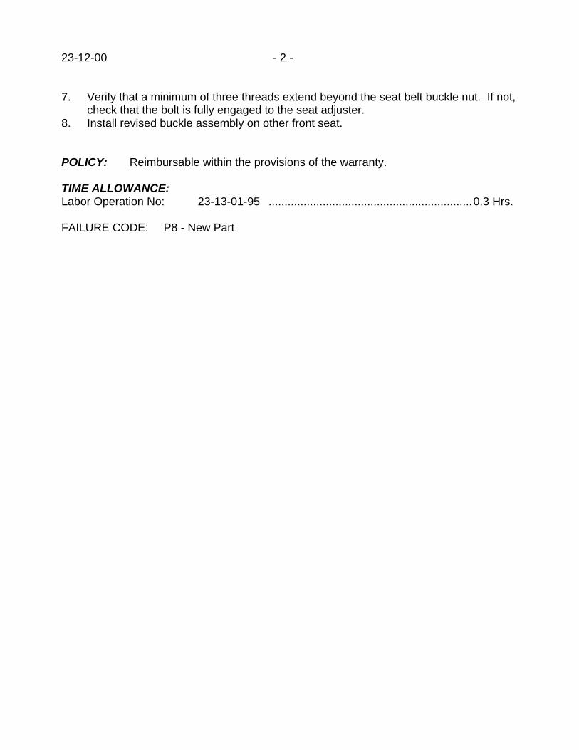
23-12-00 - 2 -
7. Verify that a minimum of three threads extend beyond the seat belt buckle nut. If not,check that the bolt is fully engaged to the seat adjuster.
8. Install revised buckle assembly on other front seat.
POLICY: Reimbursable within the provisions of the warranty.
TIME ALLOWANCE:Labor Operation No: 23-13-01-95 ................................................................0.3 Hrs.
FAILURE CODE: P8 - New Part
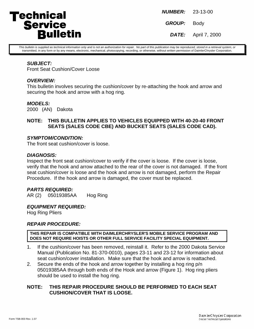
Form TSB-003 Rev. 1.07
NUMBER: 23-13-00
GROUP: Body
DATE: April 7, 2000
SUBJECT:Front Seat Cushion/Cover Loose
OVERVIEW:This bulletin involves securing the cushion/cover by re-attaching the hook and arrow andsecuring the hook and arrow with a hog ring.
MODELS:2000 (AN) Dakota
NOTE: THIS BULLETIN APPLIES TO VEHICLES EQUIPPED WITH 40-20-40 FRONTSEATS (SALES CODE CBE) AND BUCKET SEATS (SALES CODE CAD).
SYMPTOM/CONDITION:The front seat cushion/cover is loose.
DIAGNOSIS:Inspect the front seat cushion/cover to verify if the cover is loose. If the cover is loose,verify that the hook and arrow attached to the rear of the cover is not damaged. If the frontseat cushion/cover is loose and the hook and arrow is not damaged, perform the RepairProcedure. If the hook and arrow is damaged, the cover must be replaced.
PARTS REQUIRED:AR (2) 05019385AA Hog Ring
EQUIPMENT REQUIRED:Hog Ring Pliers
REPAIR PROCEDURE:
1. If the cushion/cover has been removed, reinstall it. Refer to the 2000 Dakota ServiceManual (Publication No. 81-370-0010), pages 23-11 and 23-12 for information aboutseat cushion/cover installation. Make sure that the hook and arrow is reattached.
2. Secure the ends of the hook and arrow together by installing a hog ring p/n05019385AA through both ends of the Hook and arrow (Figure 1). Hog ring pliersshould be used to install the hog ring.
NOTE: THIS REPAIR PROCEDURE SHOULD BE PERFORMED TO EACH SEATCUSHION/COVER THAT IS LOOSE.
This bulletin is supplied as technical information only and is not an authorization for repair. No part of this publication may be reproduced, stored in a retrieval system, ortransmitted, in any form or by any means, electronic, mechanical, photocopying, recording, or otherwise, without written permission of DaimlerChrysler Corporation.
THIS REPAIR IS COMPATIBLE WITH DAIMLERCHRYSLER'S MOBILE SERVICE PROGRAM ANDDOES NOT REQUIRE HOISTS OR OTHER FULL SERVICE FACILITY SPECIAL EQUIPMENT.
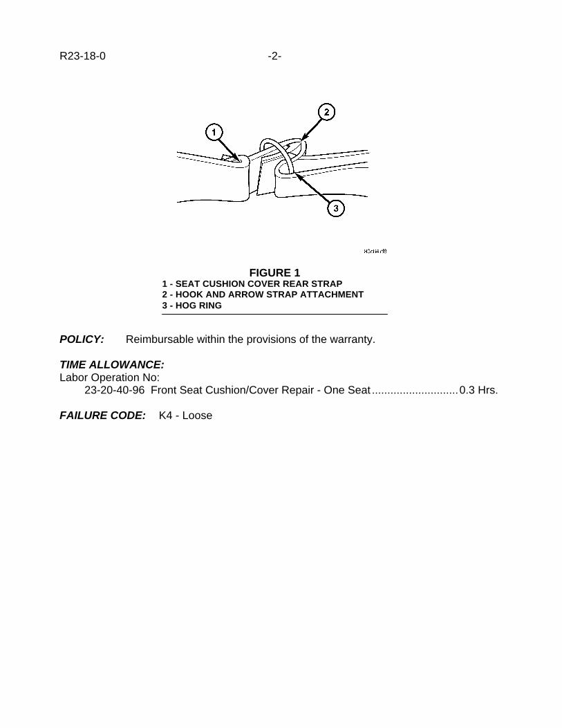
R23-18-0 -2-
POLICY: Reimbursable within the provisions of the warranty.
TIME ALLOWANCE:Labor Operation No:
23-20-40-96 Front Seat Cushion/Cover Repair - One Seat ............................0.3 Hrs.
FAILURE CODE: K4 - Loose
FIGURE 11 - SEAT CUSHION COVER REAR STRAP2 - HOOK AND ARROW STRAP ATTACHMENT3 - HOG RING
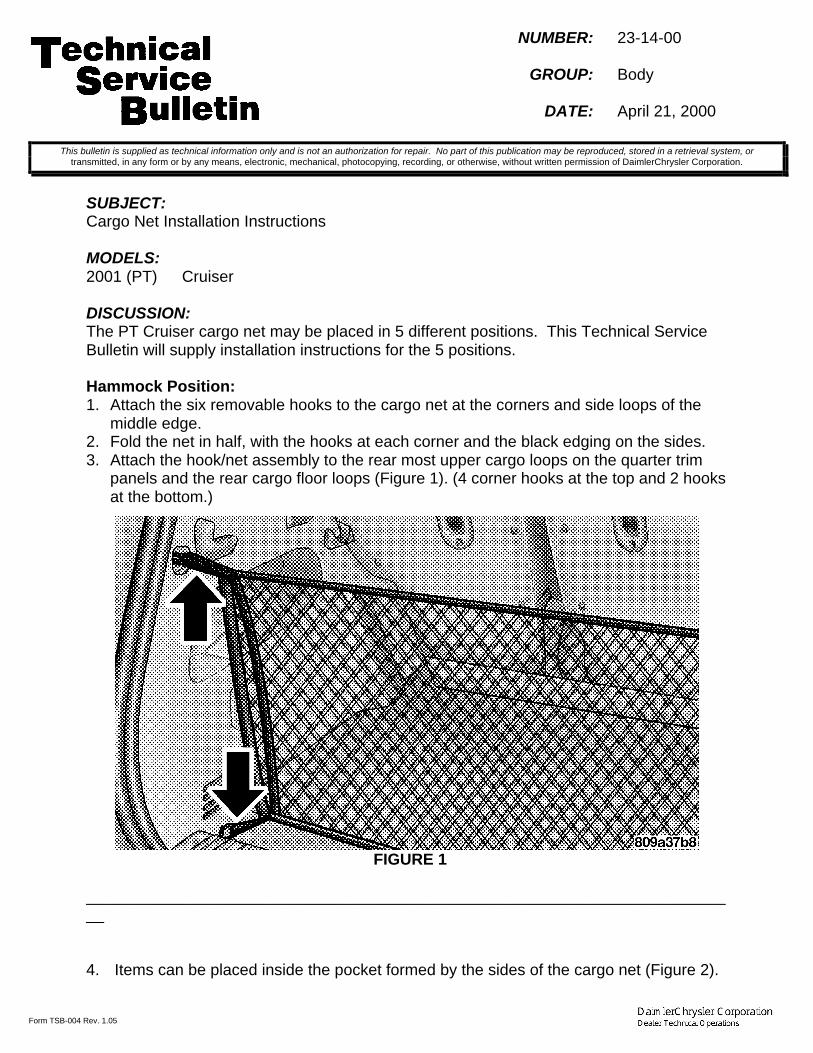
Form TSB-004 Rev. 1.05
NUMBER: 23-14-00
GROUP: Body
DATE: April 21, 2000
SUBJECT:Cargo Net Installation Instructions
MODELS:2001 (PT) Cruiser
DISCUSSION:The PT Cruiser cargo net may be placed in 5 different positions. This Technical ServiceBulletin will supply installation instructions for the 5 positions.
Hammock Position:1. Attach the six removable hooks to the cargo net at the corners and side loops of the
middle edge.2. Fold the net in half, with the hooks at each corner and the black edging on the sides.3. Attach the hook/net assembly to the rear most upper cargo loops on the quarter trim
panels and the rear cargo floor loops (Figure 1). (4 corner hooks at the top and 2 hooksat the bottom.)
FIGURE 1
__________________________________________________________________________
4. Items can be placed inside the pocket formed by the sides of the cargo net (Figure 2).
This bulletin is supplied as technical information only and is not an authorization for repair. No part of this publication may be reproduced, stored in a retrieval system, ortransmitted, in any form or by any means, electronic, mechanical, photocopying, recording, or otherwise, without written permission of DaimlerChrysler Corporation.

23-14-00 -2-
FIGURE 2
_________________________________________________________________________
Top Of Shelf In Middle and Floor Positions:1. Fold the net in half, with the hooks at each corner and the black edging on the sides.2. Place the cargo net corner loops over the corner hooks on underside of the rear shelf
panel (Figure 3).
FIGURE 3

_______________________________________________________________________-3- 23-14-00
3. Items can be placed on top of the rear shelf panel with the net holding them secure(Figure 4).
NOTE: IT MAY BE NECESSARY TO REMOVE THE HOOKS FROM THE CARGO NETIN THIS POSITION.
WARNING: DO NOT LOAD OBJECTS ON THE REAR SHELF PANEL IN POSITION 1(TOP). IN AN ACCIDENT OBJECTS COULD STRIKE THE OCCUPANTSCAUSING SERIOUS OR FATAL INJURY.
FIGURE 4
_________________________________________________________________________
Floor and Upper Rear Cargo Loops:1. Attach the six removable hooks to the cargo net at the corners and the middle edge.2. Attach the 4 hooks on the corner of the cargo net to the cargo floor loops and the
remaining 2 hooks to the upper rear loops on the quarter trim panel (Figure 5).
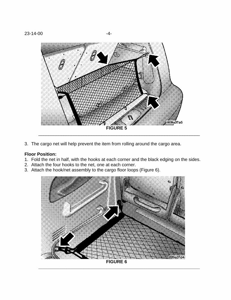
23-14-00 -4-
FIGURE 5 ________________________________________________________________
3. The cargo net will help prevent the item from rolling around the cargo area.
Floor Position:1. Fold the net in half, with the hooks at each corner and the black edging on the sides.2. Attach the four hooks to the net, one at each corner.3. Attach the hook/net assembly to the cargo floor loops (Figure 6).
FIGURE 6 ________________________________________________________________
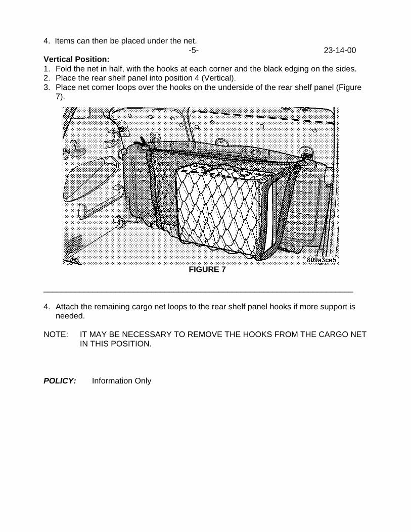
4. Items can then be placed under the net.-5- 23-14-00
Vertical Position:1. Fold the net in half, with the hooks at each corner and the black edging on the sides.2. Place the rear shelf panel into position 4 (Vertical).3. Place net corner loops over the hooks on the underside of the rear shelf panel (Figure
7).
FIGURE 7
_____________________________________________________________________
4. Attach the remaining cargo net loops to the rear shelf panel hooks if more support isneeded.
NOTE: IT MAY BE NECESSARY TO REMOVE THE HOOKS FROM THE CARGO NETIN THIS POSITION.
POLICY: Information Only


Form TSB-003 Rev. 1.07
NUMBER: 23-15-00
GROUP: Body
DATE: April 21, 2000
SUBJECT:Sliding Door Will Not Open And/Or Close/Latch
OVERVIEW:This bulletin involves installing revised sliding door rear latch assembly and latch rods andmodifying the rear latch opening.
MODELS:1998 - 2000 (AB) Ram Van/Wagon
NOTE: THIS BULLETIN APPLIES TO VEHICLES EQUIPPED WITH THE SLIDINGSIDE DOOR (SALES CODE GKF) BUILT BEFORE FEBRUARY 26, 2000(MDH 0226XX).
SYMPTOM/CONDITION:The sliding door will not open and/or will not close/latch.
DIAGNOSIS:DOOR WILL NOT OPEN
1. Remove the sliding door trim panel attaching screws.2. Remove the door pull handle (Figure 1).
This bulletin is supplied as technical information only and is not an authorization for repair. No part of this publication may be reproduced, stored in a retrieval system, ortransmitted, in any form or by any means, electronic, mechanical, photocopying, recording, or otherwise, without written permission of DaimlerChrysler Corporation.
FIGURE 11 - CLIP RETAINER 2 - TRIM PANEL3 - SLIDING CARGO DOOR 4 - NYLON NUT5 - DOOR PULL HANDLE 6 - SCREW7 - TRIM PANEL 8 - CLIP RETAINER

23-15-00 -2-
3. Using a trim removal tool, carefully pry the trim panel away from the door inner panel.4. Separate the trim panel from the sliding door.5. Remove the sliding door inside handle attaching screw (Figure 2).
6. Remove the inside sliding door handle and spacers.7. Remove the lock knob from the knob latch rod.8. Remove the latch cover screws from the door panel.9. Remove the cover from the door panel.10. Inspect the front latch-to-rear latch control rod. If the rod is positioned as shown in
Figure 3, the rear latch has over-traveled and jammed. Use a screwdriver to pry thelatch rod rearward to dislodge the latch rod. A dislodged rod can be identified by therod being free to move fore and aft by grasping the rod with your hand. If the rod isnot positioned as shown in Figure 3, this bulletin will not correct a door that will notopen complaint. Further diagnosis is required.
FIGURE 21 - KNOB2 - COVER3 - HANDLE4 - SCREW5 - SPACER6 - NUT

-3- 23-15-00
11. Remove the rear door latch attaching screws (Figure 4).
12. With the rear latch loose, push open the rear of the door enough to disconnect therear latch rods (Figure 5).
FIGURE 31 - LATCH ROD
FIGURE 4

23-15-00 -4-
13. Remove the rear latch.14. Inspect the rear latch reinforcement on the rear latch opening of the inner door panel
for a high trim condition as shown in Figure 6. If the reinforcement sticks up higherthan the opening, perform the Repair Procedure. If the rod is not positioned as shownin Figure 3 and/or the latch reinforcement does not stick up higher than the opening,this bulletin will not correct a door that will not open complaint. Further diagnosis isrequired.
FIGURE 51 - OUTER SLIDING DOOR PANEL2 - LATCH ROD3 - INNER SLIDING DOOR PANEL

-5- 23-15-00
DOOR WILL NOT CLOSE/LATCH
1. Remove the sliding door trim panel attaching screws.2. Remove the door pull handle (Figure 1).3. Using a trim removal tool, carefully pry the trim panel away from the door inner panel.4. Separate the trim panel from the sliding door.5. Inspect the front latch-to-rear latch control rod to ensure that the rod clips are
attached. Perform the Repair Procedure if the rod clips are not attached.6. Disconnect both front latch-to-rear latch control rods.7. Remove the rear latch attaching screws.8. Separate the rear latch from the inner door panel.9. Inspect the rear latch torsional spring to ensure that it is properly positioned. If the
rear latch torsional spring is NOT positioned as shown in Figure 7, perform the RepairProcedure. If the spring is properly positioned and the latch rod clips were attached(Step 5), this bulletin will not correct a door that will not close/latch complaint. Furtherdiagnosis is required.
FIGURE 61 - REAR LATCH REINFORCEMENT2 - REAR LATCH OPENING

23-15-00 -6-
PARTS REQUIRED:1 55076381AB Rod, Front Latch-To-Rear Latch1 55346503AB Rod, Front Latch-To-Rear Latch1 55347099AC Assembly, Rear LatchAR (1) NPN Primer, Brushable
REPAIR PROCEDURE:
1. Remove the rear latch assembly (if not already performed). Refer to the 2000 RamVan/Wagon Service Manual (Publication No. 81-370-0007), page 23-42 “SlidingCargo Door Rear latch Removal.”
2. Remove the sliding door inside handle attaching screw (Figure 2) (if not alreadyperformed).
3. Remove the inside sliding door handle and spacers (if not already performed).4. Remove the lock knob from the knob latch rod (if not already performed).5. Remove the latch cover screws from the door panel (if not already performed).6. Remove the cover from the door panel (if not already performed).7. Remove the front latch-to-rear latch control rods from the front latch assembly.8. Remove the latch rods from the inner door panel.9. Using a grinder, grind down the rear latch reinforcement trim edge so that the
reinforcement is flush with the inner door panel rear latch opening.10. To prevent corrosion, apply a brushable primer to the exposed bare metal.11. Connect the latch rods p/n 55076381AB and p/n 55346503AB to the front latch.
THIS REPAIR IS COMPATIBLE WITH DAIMLERCHRYSLER'S MOBILE SERVICE PROGRAM ANDDOES NOT REQUIRE HOISTS OR OTHER FULL SERVICE FACILITY SPECIAL EQUIPMENT.
FIGURE 71 - REAR LATCH TORSIONAL SPRING2 - REAR LATCH ASSEMBLY

-7- 23-15-00
12. Position the rear latch p/n 55347099AC near the rear latch opening.13. Attach the latch rods to the rear latch.14. Install the latch screws in the door inner panel. Tighten the screws to 11 N•m (95 in.
lbs).15. Position the front latch cover onto the inner door panel with the knob latch rod and the
outside handle shaft inserted in the cover holes.16. Install the cover screws in the door panel.17. Position the inside door handle spacers and the inside handle onto the outside handle
shaft. Verify both spacers are installed.18. Attach the inside handle with the screw.19. Install lock knob.20. Position the door trim panel on the door inner panel and press inward around the
edge of the panel.21. Position the door pull handle onto the trim panel with the screw holes aligned.22. Install the pull handle screws.
POLICY: Reimbursable within the provisions of the warranty.
TIME ALLOWANCE:Labor Operation No: 23-41-22-90 ................................................................0.7 Hrs.
FAILURE CODE: P8 - New Part

Form TSB-003 Rev. 1.07
NUMBER: 23-16-00
GROUP: Body
DATE: Apr. 28, 2000
SUBJECT:Buzz/ Hum From Left/Right Front Door Speaker
OVERVIEW:This bulletin involves replacing the front door water dam with a revised water dam.
MODELS:2001 (PT) PT Cruiser
NOTE: THIS TECHNICAL SERVICE BULLETIN APPLIES TO VEHICLES BUILTPRIOR TO APRIL 7, 2000 (MDH 0407XX).
SYMPTOM/CONDITION:The front door water dam may contact the speaker and create a buzz/hum type sound.
DIAGNOSIS:Turn the radio up to mid range and listen for a buzzing/humming type sound. It may benecessary to switch from full left to full right to duplicate the condition. If the noise is heardor the customer has reported a buzz/hum sound from the speaker area with the radio on,perform the Repair Procedure.
PARTS:1 05027192AB Dam, Front Door Water - Right1 05027193AB Dam, Front Door Water - Left
REPAIR PROCEDURE:
1. Remove the door trim panel following the procedure in the 2001 PT Cruiser ServiceManual (Publication No. 81-370-1111) on page 23-39.
2. Remove the speaker following the procedure in the 2001 PT Cruiser Service Manual(Publication No. 81-370-1111) on page 8F-9.
3. Remove the front door water dam following the procedure in the 2001 PT CruiserService Manual (Publication No. 81-370-1111) beginning on page 23-39.
4. Install the new front door water dam.5. Install the speaker.6. Install the door trim panel.7. Repeat steps 1 trough 6 for the other door.8. With the radio on verify that the buzz/hum has been eliminated.
This bulletin is supplied as technical information only and is not an authorization for repair. No part of this publication may be reproduced, stored in a retrieval system, ortransmitted, in any form or by any means, electronic, mechanical, photocopying, recording, or otherwise, without written permission of DaimlerChrysler Corporation.
THIS REPAIR IS COMPATIBLE WITH DAIMLERCHRYSLER'S MOBILE SERVICE PROGRAM ANDDOES NOT REQUIRE HOISTS OR OTHER FULL SERVICE FACILITY SPECIAL EQUIPMENT.

23-16-00 -2-
POLICY: Reimbursable within the provisions of the warranty.
TIME ALLOWANCE:Labor Operation No: 23-51-07-90 ...............................................................0.8 Hrs.
FAILURE CODE: P8 - New Part

Form TSB-003 Rev. 1.07
NUMBER: 23-17-00
GROUP: Body
DATE: May 5, 2000
SUBJECT:Cargo Cover Shade Bracket Breaks
OVERVIEW:This bulletin involves installing a cargo cover shade bracket repair kit.
MODELS:1999 - 2000 (WJ) Grand Cherokee
SYMPTOM/CONDITION:The cargo cover shade bracket may break, rendering the cover inoperable. A repair kithas been developed to eliminate the need to replace the cover assembly.
DIAGNOSIS:If the cargo cover bracket on the end of the shade is broke, perform the Repair Procedure.
PARTS REQUIRED:AR 05017679AA Cargo Cover Repair Kit - Agate (AZ trim)AR 05017680AA Cargo Cover Repair Kit - Camel (K5 trim)AR 05017681AA Cargo Cover Repair Kit - Taupe (L5 trim)
EQUIPMENT REQUIRED:Rivet GunDrill - 1/8 " bit
REPAIR PROCEDURE:
1. Remove the cargo cover.2. Using a drill and 1/8 in. drill bit, drill out the existing rivets from the bracket (See
Figure 1).
This bulletin is supplied as technical information only and is not an authorization for repair. No part of this publication may be reproduced, stored in a retrieval system, ortransmitted, in any form or by any means, electronic, mechanical, photocopying, recording, or otherwise, without written permission of DaimlerChrysler Corporation.
THIS REPAIR IS COMPATIBLE WITH DAIMLERCHRYSLER'S MOBILE SERVICE PROGRAM ANDDOES NOT REQUIRE HOISTS OR OTHER FULL SERVICE FACILITY SPECIAL EQUIPMENT.

23-17-00 -2-
1. Bracket2. Rivets_________________________________
FIGURE 1
3. Remove the bracket.4. Position the new bracket from the repair kit and align the bracket with the original
holes.5. Install the new rivets using the rivet tool.6. Repeat this procedure for the other side of the shade.7. Install the cargo cover
POLICY: Reimbursable within the provisions of the warranty.
TIME ALLOWANCE:Labor Operation No: 23-21-45-93 ................................................................0.2 Hrs.
FAILURE CODE: P8 - New Part

Form TSB-003 Rev. 1.07
NUMBER: 23-18-00
GROUP: Body
DATE: May 5, 2000
SUBJECT:Hardtop Roof Sag
OVERVIEW:This bulletin involves installing foam spacers on the hardtop.
MODELS:1999 - 2000 (TJ) Wrangler
SYMPTOM/CONDITION:The hardtop roof may sag in the middle. This can cause accumulation of water in themiddle of the roof after a rain.
DIAGNOSIS:Inspect the roof for the presence of sag, or if customers complain of water accumulating onthe roof. Perform the Repair Procedure.
PARTS REQUIRED:2 55177489AA Foam Block
REPAIR PROCEDURE:
1. Remove the hardtop attaching screws from the sides at the quarter panels.2. Loosen the windshield header attaching clamps to allow for a raising of the top.3. Make two marks on the roof, 6 cm (2.5 in.) on both sides of the center roof rib, directly
above the sport bar as shown in Figure 1.4. Raise the top enough to allow for installing the foam blocks. Clean the roof area with
isopropyl alcohol. Install the blocks as shown in Figure 1, by removing the protectivetape from the adhesive. The foam blocks must be centered directly above the sportbar, sitting on the sport bar pad.
5. Make sure that the top is centered at the windshield frame and quarter panel. Installand tighten the quarter panel screws.
6. Tighten the header clamps.
This bulletin is supplied as technical information only and is not an authorization for repair. No part of this publication may be reproduced, stored in a retrieval system, ortransmitted, in any form or by any means, electronic, mechanical, photocopying, recording, or otherwise, without written permission of DaimlerChrysler Corporation.
THIS REPAIR IS COMPATIBLE WITH DAIMLERCHRYSLER'S MOBILE SERVICE PROGRAM ANDDOES NOT REQUIRE HOISTS OR OTHER FULL SERVICE FACILITY SPECIAL EQUIPMENT.

23-18-00 -2-
1. Foam Block______________________________
FIGURE 1
POLICY: Reimbursable within the provisions of the warranty.
TIME ALLOWANCE:Labor Operation No: 23-85-41-94 ................................................................0.3 Hrs.
FAILURE CODE: P8 - New Part
Form TSB-003 Rev. 1.08 February 3, 2000
NUMBER: 23-19-00
GROUP: Body
DATE: May 5, 2000
THIS BULLETIN SUPERSEDES TECHNICAL SERVICE BULLETIN 23-08-99, DATEDMAR. 5, 1999, WHICH SHOULD BE REMOVED FROM YOUR FILES AND NOTED INTHE 1999 TECHNICAL SERVICE BULLETIN MANUAL (PUBLICATION NO. 81-699-00004). THE REVISION ADDS ADDITIONAL MODEL YEARS AND ARE HIGHLIGHTEDWITH **ASTERISKS.**
SUBJECT:Instrument Panel Creak
OVERVIEW:This bulletin involves loosening the instrument panel and providing additional clearancebetween the A-pillar inner panel and dash panel.
MODELS:1994 - **2001** (BR/BE) Ram Trucks
SYMPTOM/CONDITION:A creak or squeak may be present near the left and/or right side(s) of the instrument panel.The noise is caused by the sheet metal joint between the A-pillar and the dash panelplenum lower rubbing together.
DIAGNOSIS:Drive the vehicle slowly over a bump that will allow the body to twist, such as a drivewayapproach, to verify the condition.
NOTE: IN SOME CASES, THIS CREAK CAN BE PRODUCED BY HAVING ANASSISTANT STAND ON THE FRONT BUMPER ON THE SAME SIDE AS THESQUEAK/CREAK AND BOUNCING THE VEHICLE UP AND DOWN WHILEYOU ARE LISTENING FOR THE CREAK INSIDE THE CAB.
If an instrument panel squeak/creak can be heard coming from the A-pillar area, open thehood of the vehicle and inspect the 3-T welds (cowl panel welds) (Figure 1) located aft ofthe hood hinge and inside of the fender. If the 3-T welds appear cracked or rusted, refer tothe appropriate Ram Truck Service Manual Group 23 for sheet metal weld information.
This bulletin is supplied as technical information only and is not an authorization for repair. No part of this publication may be reproduced, stored in a retrieval system, ortransmitted, in any form or by any means, electronic, mechanical, photocopying, recording, or otherwise, without written permission of DaimlerChrysler Corporation.

23-19-00 -2-
NOTE: IT MAY BE NECESSARY TO HAVE AN ASSISTANT STAND ON THE FRONTBUMPER ON THE SAME SIDE AS THE SQUEAK/CREAK AND BOUNCETHE VEHICLE UP AND DOWN WHILE YOU ARE LISTENING FOR THECREAK. IF THE SQUEAK/CREAK CAN BE HEARD, SPRAY PENETRATINGLUBRICANT ON THE 3-T WELDS. IF THE SQUEAK/CREAK ISELIMINATED, REFER TO THE APPROPRIATE RAM TRUCK SERVICEMANUAL GROUP 23 FOR SHEET METAL WELD INFORMATION.
If the condition is present and the 3-T welds are not causing the squeak/creak, perform theRepair Procedure.
PARTS REQUIRED:AR (1) NPN Body Seam Sealant, 3M - 08302 (or equivalent)
REPAIR PROCEDURE:1. Record the radio station presets.2. Disconnect and isolate the battery negative cable.3. Remove the left and right cowl side trim.4. Remove the knee blocker beneath the steering column.5. Disconnect the shift indicator cable.6. Loosen the lower instrument panel attaching bolts.
FIGURE 11 - HOOD2 - COWL3 - 3-T WELDS4 - FENDER
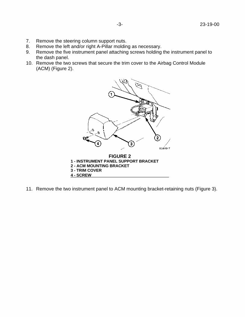
-3- 23-19-00
7. Remove the steering column support nuts.8. Remove the left and/or right A-Pillar molding as necessary.9. Remove the five instrument panel attaching screws holding the instrument panel to
the dash panel.10. Remove the two screws that secure the trim cover to the Airbag Control Module
(ACM) (Figure 2).
11. Remove the two instrument panel to ACM mounting bracket-retaining nuts (Figure 3).
FIGURE 21 - INSTRUMENT PANEL SUPPORT BRACKET2 - ACM MOUNTING BRACKET3 - TRIM COVER4 - SCREW
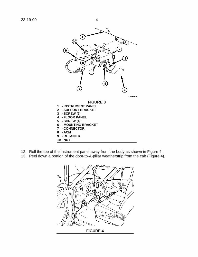
23-19-00 -4-
12. Roll the top of the instrument panel away from the body as shown in Figure 4.13. Peel down a portion of the door-to-A-pillar weatherstrip from the cab (Figure 4).
FIGURE 31 - INSTRUMENT PANEL2 - SUPPORT BRACKET3 - SCREW (2)4 - FLOOR PANEL5 - SCREW (4)6 - MOUNTING BRACKET7 - CONNECTOR8 - ACM9 - RETAINER10 - NUT
FIGURE 4
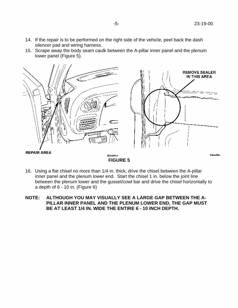
-5- 23-19-00
14. If the repair is to be performed on the right side of the vehicle, peel back the dashsilencer pad and wiring harness.
15. Scrape away the body seam caulk between the A-pillar inner panel and the plenumlower panel (Figure 5).
FIGURE 5
16. Using a flat chisel no more than 1/4 in. thick, drive the chisel between the A-pillarinner panel and the plenum lower end. Start the chisel 1 in. below the joint linebetween the plenum lower and the gusset/cowl bar and drive the chisel horizontally toa depth of 6 - 10 in. (Figure 6)
NOTE: ALTHOUGH YOU MAY VISUALLY SEE A LARGE GAP BETWEEN THE A-PILLAR INNER PANEL AND THE PLENUM LOWER END, THE GAP MUSTBE AT LEAST 1/4 IN. WIDE THE ENTIRE 6 - 10 INCH DEPTH.

23-19-00 -6-
17. Repeat Step 16 by starting the chisel in the same place but drive the chisel upward ata 30o angle.
18. If necessary, perform steps 14 through 17 to the other end of the cowl panel.19. Verify the repair by having an assistant stand on the front bumper on the same side
as the squeak/creak and bouncing the vehicle up and down while you are listening forthe creak inside the cab.
20. Perform Steps 16 and 17 until the squeak/creak has been repaired.21. Reseal the area with body seam caulk (3M 08302 or equivalent) to prevent water
leaks.22. Reattach the door-to-A-pillar weatherstrip seal(s).23. Re-assemble the instrument panel to the body.24. Install the two Instrument panel to ACM mounting bracket-retaining nuts. Tighten the
nuts to 14 N•m (125 in. lbs.).25. Install the two screws that secure the trim cover to the Airbag Control Module (ACM).
Tighten the screws to 2.2 N•m (20 in. lbs.).26. Install the steering column.27. Install the knee blocker.28. Install the left and right side cowl trim.29. Reconnect the battery negative cable.30. Reset the clock and reprogram the radio station presets identified in step 1.
FIGURE 61 - FRAME/WINDSHIELD OPENING2 - GUSSETT/COWL BAR3 - PLENUM LOWER

-7- 23-19-00
POLICY: Reimbursable within the provisions of the warranty.
TIME ALLOWANCE:Labor Operation No:
23-50-01-94 Provide Clearance Between Instrument PanelSupport Joint And Cowl Side Panel (One Side) .........................1.0 Hrs.
23-50-02-92 Provide Clearance Between Instrument PanelSupport Joint And Cowl Side Panel (Both Sides).......................1.2 Hrs.
FAILURE CODE: XX - Service Adjustment


Form TSB-003 Rev. 1.07
NUMBER: 23-20-00
GROUP: Body
DATE: May, 12, 2000
SUBJECT:Body Mounted Door Opening Weatherstrip Loose
OVERVIEW:This bulletin involves installing clips to secure weatherstrips to the pinch flange.
MODELS:1998 - 2000 (LH) Concorde/Intrepid/LHS/300M
SYMPTOM/CONDITION:Body mounted weatherstrip (primary weatherstrip) is loose or pulls away easily from thepinch flange.
DIAGNOSIS:Inspect weatherstrip where it has pulled away from the pinch flange for damage. Ifweatherstrip is damaged, replace it. If the weatherstrip is OK, perform the RepairProcedure.
PARTS REQUIRED:1 05019585AA Clip, Weatherstrip
REPAIR PROCEDURE:
1. Install clip, p/n 05019585AA, on the pinch flange in area where weatherstrip isloose. One clip in the center of the pulled away area should be enough (Figure 1).
2. Install the weatherstrip over the clips and pinch flange.
NOTE: WEATHERSTRIPS CAN BE INSTALLED WITHOUT REMOVING TRIMPANELS.
This bulletin is supplied as technical information only and is not an authorization for repair. No part of this publication may be reproduced, stored in a retrieval system, ortransmitted, in any form or by any means, electronic, mechanical, photocopying, recording, or otherwise, without written permission of DaimlerChrysler Corporation.
THIS REPAIR IS COMPATIBLE WITH DAIMLERCHRYSLER'S MOBILE SERVICE PROGRAM ANDDOES NOT REQUIRE HOISTS OR OTHER FULL SERVICE FACILITY SPECIAL EQUIPMENT.

23-20-00 - 2 -
3. Repeat procedure on all loose primary weatherstrips as necessary.
POLICY: Reimbursable within the provisions of the warranty.
TIME ALLOWANCE:Labor Operation No: 23-51-09-94 Clip, Install One Or Four......................... 0.2 Hrs.
FAILURE CODE: P8 - New Part
FIGURE 1 BODY MOUNTED WEATHERSTRIP1 - CLIP2 - PINCH FLANGE
Form TSB-003 Rev. 1.07
NUMBER: 23-21-00
GROUP: Body
DATE: May 19, 2000
SUBJECT:Front Seat Binds or Sticks when Adjusting the Seat Fore and Aft (Manual Seats).
OVERVIEW:This bulletin involves removing sealer/sound deadener from the floor pan.
MODELS:2000 (WJ) Grand Cherokee
NOTE: THIS BULLETIN APPLIES TO VEHICLES EQUIPPED WITH MANUAL SEATADJUSTERS.
SYMPTOM/CONDITION:The front seat adjuster may bind or stick when adjusting the seat fore and aft.
DIAGNOSIS:If the vehicle exhibits the condition, perform the Repair Procedure.
REPAIR PROCEDURE:
1. Remove the seat from the floor.2. Pull the carpeting back and inspect the floor pan in the all areas where the seat
attaches.3. If any sealer or sound deadener over-spray build up is present in the area where the
seat bolts to the floor, scrape away the material with an appropriate tool.4. Coat any bare metal with a corrosion preventing primer and allow the primer to dry.5. Repositions the carpet and install the seat.
POLICY: Reimbursable within the provisions of the warranty.
TIME ALLOWANCE:Labor Operation No: 23-50-40-90 ................................................................0.3 Hrs.
FAILURE CODE: 07 - Binds, Sticks or Seized
This bulletin is supplied as technical information only and is not an authorization for repair. No part of this publication may be reproduced, stored in a retrieval system, ortransmitted, in any form or by any means, electronic, mechanical, photocopying, recording, or otherwise, without written permission of DaimlerChrysler Corporation.
THIS REPAIR IS COMPATIBLE WITH DAIMLERCHRYSLER'S MOBILE SERVICE PROGRAM ANDDOES NOT REQUIRE HOISTS OR OTHER FULL SERVICE FACILITY SPECIAL EQUIPMENT.


Form TSB-003 Rev. 1.07
NUMBER: 23-22-00
GROUP: Body
DATE: May 26, 2000
SUBJECT:B-Pillar And C-Pillar Applique On Doors Have A Brown Haze or Appear Discolored
OVERVIEW:This bulletin involves using a cleaner to remove the discoloration.
MODELS:2001 (PT) PT Cruiser
SYMPTOM/CONDITION:The B-pillar appliques used on the exterior of the front doors and the B & C pillar appliqueson the rear doors may have a brown haze or appear discolored. This is caused by contactwith certain phosphates used in some types of car wash soap. The discoloration can alsobe described as having iridescent blue spots on the B-pillar and/or C-pillar applique.
DIAGNOSIS:Visually inspect the B-pillar appliques on all 4 doors and the C-pillar applique on the reardoors, if the discoloration, brown haze or blue spots are found, perform the RepairProcedure.
PARTS REQUIRED:1 05017020AA Mopar Swirl Free CleanerNPN 3M High Performance Wipe Cloth or Equivalent
REPAIR PROCEDURE:
1. The appliques must be cool and dry before beginning the repair procedure.2. Apply a small amount (dime size) of the Mopar Swirl Free Cleaner to a clean and
dry 3M High Performance Wipe Cloth or equivalent.3. Starting at the top of the B-pillar applique, rub the cleaner into a small section of the
B-pillar. Continue to rub until nearly dry. Clean the remainder of the B-pillar usingthe same process.
4. Allow the complete B-pillar applique to dry. Dry time is approximately 2 minutes.5. Use a clean, dry 100% cotton towel and wipe off any remaining cleaner residue.6. Repeat the procedure for the remaining B- pillar and C-pillar appliques as needed.
This bulletin is supplied as technical information only and is not an authorization for repair. No part of this publication may be reproduced, stored in a retrieval system, ortransmitted, in any form or by any means, electronic, mechanical, photocopying, recording, or otherwise, without written permission of DaimlerChrysler Corporation.
THIS REPAIR IS COMPATIBLE WITH DAIMLERCHRYSLER'S MOBILE SERVICE PROGRAM ANDDOES NOT REQUIRE HOISTS OR OTHER FULL SERVICE FACILITY SPECIAL EQUIPMENT.
23-22-00 -2-
POLICY: Reimbursable within the provisions of the warranty.
TIME ALLOWANCE:Labor Operation No: 23-05-11-94 ................................................................0.2 Hrs.
FAILURE CODE: 69 - Discolored

Form TSB-003 Rev. 1.08 February 3, 2000
NUMBER: 23-23-00
GROUP: Body
EFFECTIVE DATE: June 30, 2000
SUBJECT:Ignition Key Will Not Turn And/Or Cannot Be Removed
OVERVIEW:This bulletin involves performing one or any combination of the following procedures;cutting a new ignition key, and/or adjusting transmission shifter cable, and/or replacing theignition lock cylinder and/or replacing the ignition lock housing and switch assembly.
MODELS:1997 – 2000 (NS) Town & Country/Caravan/Voyager
SYMPTOM/CONDITION:1. Cannot turn the ignition key when attempting to start vehicle, this condition may be
intermittent.2. Unable to remove the ignition key from the lock cylinder.
PARTS REQUIRED:AR (1) 04778115 KeyAR (1) 05003843AB Cylinder, Ignition LockAR (1) 04690523 Assembly, Ignition Switch and Lock Housing
EQUIPMENT POSSIBLY REQUIRED:Key Cutter such as Pentastar Service Equipment (PSE) IL-MK1-P2627 or IL-ECM100T-27 Torx BitT-25 Torx BitT-10 Tamper Resistant Torx BitSR-706059 Lock Cylinder Build Kit, Pentastar Service Equipment (PSE)
DIAGNOSIS / REPAIR PROCEDURE:
SYMPTOM/CONDITION ONE
1. Ensure the steering wheel is centered and the vehicle is positioned on a level surface.2. Disconnect the negative battery cable.
This bulletin is supplied as technical information only and is not an authorization for repair. No part of this publication may be reproduced, stored in a retrieval system, ortransmitted, in any form or by any means, electronic, mechanical, photocopying, recording, or otherwise, without written permission of DaimlerChrysler Corporation.
THIS REPAIR IS COMPATIBLE WITH DAIMLERCHRYSLER'S MOBILE SERVICE PROGRAM ANDDOES NOT REQUIRE HOISTS OR OTHER FULL SERVICE FACILITY SPECIAL EQUIPMENT.

23-23-00 -2-
3. Insert ignition key into the ignition lock cylinder and attempt to rotate the key to thestart position and then the accessory position.
4. If the key does not turn, remove the key from the lock cylinder and rotate it 180o.Reinsert the key into the lock cylinder and attempt to rotate the key. If the key doesnot turn skip to step 14. If the key does turn make a new key.
NOTE: USE THE KEY CODE ON THE VEHICLE INVOICE TO CORRECTLY CUT THENEW KEY. KEY CODES ARE ALSO AVAILABLE USING THE D.I.A.L.SYSTEM, MAIN MENU OPTION 13.DO NOT USE A KEY DUPLICATOR TO MAKE THE NEW KEY.
5. Insert the new ignition key into the ignition lock cylinder and attempt to rotate the keyto the start position and then the accessory position.
6. If the key turns, remove the key from the lock cylinder and turn it over 180o andreinsert the key into the lock cylinder. Attempt to rotate the key.
7. If the key turns, repeat steps 5 and 6 ten times. If the key continues to rotate smoothlythe repair is complete. If the key fails to turn smoothly at each rotation attempt,continue to step 8.
8. Remove the ignition lock cylinder using the procedure outlined on page 8D-29 of the2000 Town & Country, Caravan and Voyager Service Manual (Publication No. 81-370-0005). DO NOT ATTEMPT TO DISASSEMBLE THE LOCK CYLINDER.
9. Build a new lock cylinder to the key code on the vehicle invoice, using the instructionsin the Pentastar Service Equipment SR-706059 Lock Cylinder Build Kit.
10. Install the new ignition lock cylinder using the procedure outlined on page 8D-29 of the2000 Town & Country, Caravan and Voyager Service Manual (Publication No. 81-370-0005).
11. Insert the new ignition key into the new ignition lock cylinder and attempt to rotate thekey to the start position and then the accessory position.
12. If the key turns, remove the key from the lock cylinder and turn it over 180o andreinsert the key into the lock cylinder. Attempt to rotate the key.
13. If the key turns, repeat steps 11 and 12 ten times. If the key continues to rotatesmoothly the repair is complete. If the key fails to turn smoothly at each rotationattempt, continue to step 14.
14. Remove the ignition lock housing and ignition switch as an assembly using theprocedure outlined beginning on page 19-47 of the 2000 Town & Country, Caravanand Voyager Service Manual (Publication No. 81-370-0005).
NOTE: SKIP STEPS 13 AND 14 OF THE SERVICE MANUAL REMOVALPROCEDURE SO THE IGNITION LOCK HOUSING AND IGNITION SWITCHARE REMOVED AS AN ASSEMBLY.
15. Install a new ignition lock housing and ignition switch assembly, p/n 04690523, usingthe procedure outlined beginning on page 19-49 of the 2000 Town & Country,Caravan and Voyager Service Manual (Publication No. 81-370-0005).

-3- 23-23-00
NOTE: PRIOR TO PERFORMING STEP 2 OF THE SERVICE MANUAL LOCKHOUSING INSTALLATION PROCEDURE, INSTALL THEN REMOVE THETWO LOCK CYLINDER HOUSING MOUNTING SCREWS INTO THE LOCKHOUSING MOUNTING HOLES TO CREATE THE THREADS IN THE HOLES.FAILURE TO CREATE THE MOUNTING HOLE THREADS PRIOR TOINSTALLATION TO THE STEERING COLUMN MAY CAUSE MISALIGNMENTOF THE LOCK HOUSING TO STEERING COLUMN AND DAMAGE/BINDINGOF STEERING COLUMN MAY RESULT.STEPS 5 AND 6 OF THE SERVICE MANUAL INSTALLATION PROCEDUREFOR THE LOCK HOUSING ARE NOT NECESSARY FOR THIS TSBPROCEDURE.WHEN PERFORMING STEP 9 OF THE SERVICE MANUAL PROCEDUREUSE THE NEW LOCK CYLINDER THAT WAS BUILT IN STEP 9 OF THESYMPTOM/CONDITION ONE DIAGNOSIS / REPAIR PROCEDURE OF THISBULLETIN.
16. Insert the new ignition key into the new ignition lock cylinder and attempt to rotate thekey to the start position and then the accessory position.
17. If the key turns, remove the key from the lock cylinder and turn it over 180o andreinsert the key into the lock cylinder. Attempt to rotate the key.
18. If the key turns, repeat steps 16 and 17 ten times. If the key continues to rotatesmoothly the repair is complete.
SYMPTOM/CONDITION TWO
1. Check the operation of the shift lever. The shift lever should fall freely away from thedriver when it is brought up into the Park position.
2. If the shift lever does not seat fully up and away from the driver the column will notallow the key to be removed.
3. If binding of the shift lever is discovered, adjust the transmission shift cable using theprocedure outlined on page 21-114 of the 2000 Town & Country, Caravan andVoyager Service Manual (Publication No. 81-370-0005).
POLICY: Reimbursable within the provisions of the warranty.
TIME ALLOWANCE:Labor Operation No:
23-41-05-91 Make a New Key ..........................................................0.3 Hrs.23-41-05-92 Build a Lock Cylinder ...................................................0.6 Hrs.19-20-75-90 Replace Lock Housing & Ignition Switch Assy. ............0.8 Hrs.21-95-06-92 Adjust Transmission Shift Cable ..................................0.2 Hrs.
FAILURE CODE: P8 - New Part XX - Service Adjustment


Form TSB-003 Rev. 1.08 February 3, 2000
NUMBER: 23-24-00
GROUP: Body
DATE: Jun. 16, 2000
SUBJECT:“B” Pillar Front Door Edge Seal Loose or Missing
OVERVIEW:This bulletin involves installing a “B” pillar front door edge seal.
MODELS:2000 (LH) LHS2000 (LH) 300M (International Market)
NOTE: THIS BULLETIN APPLIES TO 300M INTERNATIONAL MARKET VEHICLESAND ALL LHS VEHICLES.
SYMPTOM/CONDITION:The “B” pillar front door edge seal may be loose or missing.
DIAGNOSIS:If the “B” pillar front door edge seal is loose or missing, perform the Repair Procedure.
PARTS REQUIRED:AR(2) 05066129AA Seal, “B” PillarAR 04467709 Mopar, Bond-All Gel
REPAIR PROCEDURE:1. Remove existing “B” pillar door edge seal if necessary and clean surface with
isopropyl alcohol.2. Apply Mopar Bond-All Gel into the entire length of the new “B” pillar door edge seal
channel (use sparingly, as the glue will seep out).3. Locate the “B” pillar door edge seal at the top edge of the “B” pillar, just below the
plastic endcap.4. Using finger pressure, push seal onto flange and follow all the way down the pillar.5. Wipe any excess glue.
POLICY: Reimbursable within the provisions of the warranty.
TIME ALLOWANCE:Labor Operation No: 23-51-16-94 Seal Replace, One or Both..................0.2 Hrs.
FAILURE CODE: P8 - New Part
This bulletin is supplied as technical information only and is not an authorization for repair. No part of this publication may be reproduced, stored in a retrieval system, ortransmitted, in any form or by any means, electronic, mechanical, photocopying, recording, or otherwise, without written permission of DaimlerChrysler Corporation.


Form TSB-003 Rev. 1.08 February 3, 2000
NUMBER: 23-25-00
GROUP: Body
DATE: Jun. 30, 2000
THIS BULLETIN SUPERSEDES TECHNICAL SERVICE BULLETIN 23-05-98, DATEDJANUARY 30, 1998 WHICH SHOULD BE REMOVED FROM YOUR FILES. ALLREVISIONS ARE HIGHLIGHTED WITH **ASTERISKS** AND INCLUDE ADDITIONALMODELS AND MODEL YEARS.
SUBJECT:Paint Fogging/Whitening
OVERVIEW:This bulletin involves removal of a fogging or staining condition from any painted surfacewhere moisture may be trapped under the clear coat.
MODELS:1996 - **2000** (JX) Sebring Convertible1995 - **2000** (PL) Neon**2001 (PT) PT Cruiser**1997 - **2001** (BR) Ram Truck
SYMPTOM/CONDITION:Painted surfaces of the vehicle that are covered for extended periods of time with front endcovers (Bras), transit films or magnetic signs may appear to have a white "milky" spot ** ondark colors, or a fogging, coffee colored spot lighter colors**.
NOTE: WHEN USING A FRONT END COVER OR MAGNETIC SIGN, FOLLOW THEMANUFACTURER'S PRECAUTIONS.
DIAGNOSIS:**Wash the affected area(s) with mild soap and water. Spot clean any area(s) to removeany difficult dirt, tar, bugs, etc. If paint fogging/whitening exist, run your hand over thesurface, if no surface condition exists perform the following Repair Procedure**.
EQUIPMENT REQUIRED:**Heat Gun**
REPAIR PROCEDURE:1. **Place a heat gun approximately 100 to 150 mm (4 to 6 inches) from the effected
area. A target surface temperature of 80o to 95o C. (180o to 200oF.) is prefered.
NOTE: DO NOT APPLY HEAT ABOVE 95o C. (200oF.) TO ANY PLASTIC PARTS.
This bulletin is supplied as technical information only and is not an authorization for repair. No part of this publication may be reproduced, stored in a retrieval system, ortransmitted, in any form or by any means, electronic, mechanical, photocopying, recording, or otherwise, without written permission of DaimlerChrysler Corporation.

23-25-00 -2-
2. Heat the effected area for approximately 2 to 4 minutes. The amount of time isdependent upon the size and shape of the affected area and the severity of thecondition.
NOTE: CIRCULATE THE HEAT GUN AROUND THE EFFECTED AREA. DO NOTALLOW HEAT TO BE DIRECTED AT ONE AREA FOR TOO LONG, PAINTDAMAGE MAY OCCUR.
3. If this Repair Procedure does not correct the condition, color-coat paint repair will berequired.
NOTE: IF PAINT "FOGGING" DAMAGE WAS CAUSED BY A FRONT END COVEROR A MAGNETIC SIGN, THE OWNER SHOULD BE CAUTIONED AGAINSTUSING THAT PRODUCT, OR A SIMILAR PRODUCT THAT MAY CREATETHE PAINT "FOGGING".**
POLICY: Reimbursable within the provisions of the warranty.
TIME ALLOWANCE:Labor Operation No: 23-60-02-90 ................................................................0.3 Hrs.
FAILURE CODE: XX - Service Adjustment

Form TSB-003 Rev. 1.07
NUMBER: 23-26-00
GROUP: Body
EFFECTIVE DATE: July 7, 2000
SUBJECT:Unable To Release Rear Seat Floor Latch (Left and/or Right) To Dump Seat Forward.
OVERVIEW:This bulletin involves installing a new e-clip to rear seat side handle release mechanismand replacing the side handle release assembly as needed.
MODELS:2001 (PT) PT Cruiser
SYMPTOM/CONDITION:Unable to release the rear seat floor latch(s) to tumble the seat forward. The cable endfitting retention wall inside of the side handle housing may be distorted not allowingenough tension to release the latch. It is also possible that the cable end fitting may bepulled through the wall.
DIAGNOSIS:Slide the front seat to the forward most position and fold the rear seat up to gain access tothe handle. Remove the rear seat side handle housing from the seat cushion pan on bothrear seats and inspect the slot in the cable end fitting retention wall (Figure 1). If the slot inthe cable end fitting retention wall is not broken, proceed to Repair Procedure A. If the slotin the cable end fitting retention wall is broken or cracked, proceed to Repair Procedure B.
FIGURE 11 - Backside Of Rear Seat Side Handle Housing (Right/ 65 Split)2 - Retention Wall_____________________________________________
This bulletin is supplied as technical information only and is not an authorization for repair. No part of this publication may be reproduced, stored in a retrieval system, ortransmitted, in any form or by any means, electronic, mechanical, photocopying, recording, or otherwise, without written permission of DaimlerChrysler Corporation.

23-26-00 -2-
PARTS REQUIRED:3 05019905AA E-ClipAR 05016786AA Release, Side Handle Assembly (Right)AR 05016787AA Release, Side Handle Assembly (Left)
REPAIR PROCEDURE:
REPAIR PROCEDURE A:1. Place the e-clip in the slot and groove in the cable end fitting. Ensure the cable end
fitting is secured at the bottom of the slot (Figure 2).
NOTE: THE RIGHT SIDE (65 SPLIT) REQUIRES AN E-CLIP ON EACH OF THETWO CABLES.
FIGURE 21 - Rear Seat Side Handle Housing (Right/65 Split)2 - E-Clip Shown Installed On Front Cable3 - Retention Wall_______________________________________
2. Install the side handle release assembly to the seat cushion pan.3. Fold the seat back into the upright position and check the floor latch function by
actuating the side handle.
THIS REPAIR IS COMPATIBLE WITH DAIMLERCHRYSLER'S MOBILE SERVICE PROGRAM ANDDOES NOT REQUIRE HOISTS OR OTHER FULL SERVICE FACILITY SPECIAL EQUIPMENT.

-3- 23-26-00
REPAIR PROCEDURE B:1. Remove the cracked/broken side handle release assembly from the cable.2. Install the new side handle release assembly onto the cable.3. Place the e-clip in the slot and groove in the cable end fitting. Ensure the cable end
fitting is secured at the bottom of the slot (Figure 2).
NOTE: THE RIGHT SIDE (65 SPLIT) REQUIRES AN E-CLIP ON EACH OF THETWO CABLES.
4. Install the side handle release assembly to the seat cushion pan.5. Fold the seat back into the upright position and check the floor latch function by
actuating the side handle.
POLICY: Reimbursable within the provisions of the warranty.
TIME ALLOWANCE:Labor Operation No: 23-42-20-91 ...............................................................0.2 Hrs.
Install E-Clip(s) to Reclining Seat Back Release Handle -Both Sides
23-42-20-92 ...............................................................0.3 Hrs.Install New Reclining Seat Back Release Handle & E-Clip(s)Both Sides
FAILURE CODE: P8 - New Part


Form TSB-003 Rev. 1.08 February 3, 2000
NUMBER: 23-27-00
GROUP: Body
DATE: July 7, 2000
SUBJECT:Power Seat Track Creak
OVERVIEW:This bulletin involves repositioning and lubricating the power seat track-locating pin.
MODELS:2000 (AN) Dakota2000 (DN) Durango
NOTE: THIS BULLETIN APPLIES TO ALL DAKOTA QUAD CAB VEHICLES ANDDURANGO VEHICLES BUILT AFTER DECEMBER 11, 1999 (MDH 121110)EQUIPPED WITH EITHER THE 40/20/40 SPLIT BENCH (SALES CODE CBE)OR BUCKET FRONT SEAT (SALES CODE CAD) WITH THE DRIVER SIDEPOWER SEAT ADJUSTMENT OPTION (SALES CODE JPS).
SYMPTOM/CONDITION:Driver power seat creaks at front outboard attachment when shifting weight or driving overbumpy roads.
DIAGNOSIS:While sitting in the seat, firmly shift weight from side to side of the seat. If a creaking noiseis heard coming from the outboard front attachment area of the seat, perform the RepairProcedure.
PARTS REQUIRED:AR (1) 04318066 Lubricant, Spray White
REPAIR PROCEDURE:
1. Remove the outboard power seat track cover (Durango Only) by removing the twophillips head screws and unsnapping the cover.
2. Remove both front M8 attaching bolts.3. With the two rear bolts still attached, lift the outboard seat track foot slightly (no more
than one inch) to expose the locator pin.4. Spray lubricant p/n 04318066 around locating pin (Figure 1). Be careful to ensure
that white lubricant does not get on the carpet.5. Position the locating pin of the outboard foot of the power seat track in the center of
the locating hole (no metal-to-metal contact). It may be required to loosen the rearpower seat track attaching bolts in order to be able to position the locator pin into thecenter of the locator hole.
This bulletin is supplied as technical information only and is not an authorization for repair. No part of this publication may be reproduced, stored in a retrieval system, ortransmitted, in any form or by any means, electronic, mechanical, photocopying, recording, or otherwise, without written permission of DaimlerChrysler Corporation.
THIS REPAIR IS COMPATIBLE WITH DAIMLERCHRYSLER'S MOBILE SERVICE PROGRAM ANDDOES NOT REQUIRE HOISTS OR OTHER FULL SERVICE FACILITY SPECIAL EQUIPMENT.

23-27-00 -2-
6. Secure the power seat track by installing the front M8 attaching bolts and tighteningall fasteners (front and rear) to 27 N•m (20 ft. lb.).
7. Attach the power seat track covers (Durango only).8. Verify the repair by performing the diagnosis again. Repeat the process until repair is
successful.
POLICY: Reimbursable within the provisions of the warranty.
TIME ALLOWANCE:Labor Operation No: 23-13-60-94 ................................................................0.2 Hrs.
FAILURE CODE: 68 - Noisy
FIGURE 11 - POWER SEAT TRACK2 - LOCATING PIN

Form TSB-003 Rev. 1.07
NUMBER: 23-28-00
GROUP: Body
DATE: Jul. 7, 2000
SUBJECT:Passenger Compartment Floor/Carpet Wet
OVERVIEW:This bulletin involves adding additional sill drain plugs.
MODELS:1996 - 2000 (JX) Sebring Convertible
SYMPTOM/CONDITION:Moisture under the passenger compartment carpet or wet carpet.
DIAGNOSIS:If the passenger compartment floor or carpets are wet inspect the sill drain holes fordebris. The sill drain holes are the normal water path from the rear of the convertible top.If debris is present, clean drain holes, and perform the Repair Procedure.
PARTS REQUIRED:2 05019082AA Plug, Sill Drain
REPAIR PROCEDURE:
1. Remove existing sill plug from the rear of the sill (front of the rear wheel well).2. Install revised plug/drain, p/n 05019082AA.3. Repeat procedure on other side of vehicle.
POLICY: Reimbursable within the provisions of the warranty.
TIME ALLOWANCE:Labor Operation No: 23-50-00-94 Both Sides ..............................................0.2 Hrs.
FAILURE CODE: P8 - New Parts
This bulletin is supplied as technical information only and is not an authorization for repair. No part of this publication may be reproduced, stored in a retrieval system, ortransmitted, in any form or by any means, electronic, mechanical, photocopying, recording, or otherwise, without written permission of DaimlerChrysler Corporation.
THIS REPAIR IS COMPATIBLE WITH DAIMLERCHRYSLER'S MOBILE SERVICE PROGRAM ANDDOES NOT REQUIRE HOISTS OR OTHER FULL SERVICE FACILITY SPECIAL EQUIPMENT.


Form TSB-004 Rev. 1.06 February 3, 2000
NUMBER: 23-29-00
GROUP: Body
DATE: Jul. 7, 2000
THIS BULLETIN SUPERSEDES TECHNICAL SERVICE BULLETIN 23-05-99, DATEDFebruary 12, 1999 WHICH SHOULD BE REMOVED FROM YOUR FILES AND NOTEDIN THE 1999 TECHNICAL SERVICE BULLETIN MANUAL (PUBLICATION NO. 81-699-00004). ALL REVISIONS ARE HIGHLIGHTED WITH **ASTERISKS** AND INCLUDEADDITIONAL MODELS.
SUBJECT:Rear Door Trim Panel Loose At Upper Rear Corner
OVERVIEW:This bulletin involves installing a screw securing the door trim panel and adding flockingtape to the interface between the rear of the door panel and sheet metal on **some**Concorde/LHS/300M vehicles.
MODELS:1998 - **2001** (LH) Concorde/Intrepid/LHS/300M
SYMPTOM/CONDITION:Rear door trim panel may be loose (pulled away from inner sheet metal) at the top rearcorner. Condition may be aggravated by slamming the door shut.
DIAGNOSIS:If door trim panel is installed properly (all fasteners secure) but can be pulled loose at theupper rear corner or loosens when the door is slammed, perform the Repair Procedure.
PARTS REQUIRED:1 06032723 Screw, Door Panel Attaching2 06504014 Clip, Door Panel Attaching, White, **1998 -2000 Model Years**1 06503204 Clip, Door Panel Attaching, Green, **1998 - 2000 Model Years**1 04773968 Tape, Flocking
**NOTE: 2001 MODEL YEAR DOOR PANEL ATTACHING CLIPS ARE REUSABLE.**
REPAIR PROCEDURE:
1. Lower window all the way down on affected door.2. Remove C-pillar flag cover.3. Place a piece of duct tape over the rear section of the belt molding weatherstrip to
protect it (Figure 1).4. Hold door trim panel in position (push down along top edge) so the inner and outer
weatherstrips are aligned.
This bulletin is supplied as technical information only and is not an authorization for repair. No part of this publication may be reproduced, stored in a retrieval system, ortransmitted, in any form or by any means, electronic, mechanical, photocopying, recording, or otherwise, without written permission of DaimlerChrysler Corporation.
THIS REPAIR IS COMPATIBLE WITH DAIMLERCHRYSLER'S MOBILE SERVICE PROGRAM ANDDOES NOT REQUIRE HOISTS OR OTHER FULL SERVICE FACILITY SPECIAL EQUIPMENT.

23-29-00 - 2 -
5. With an awl puncture the inner belt weatherstrip or drill a 1/8" pilot hole to mark thelocation on the sheet metal inner panel (Figure 1). The mark/hole should beapproximately 35 mm (1 3/8 in.) from the rear of the panel to avoid the locating holealready in the sheet metal inner.
FIGURE 16. Cut away any portion of the black foam strip wrapped around the inner belt
weatherstrip interfering with the awl hole. This is to allow the screw to be visible forfuture repairs. **Install screw, p/n 06032723, on Dodge vehicles and other models ifthere is already anti-squeak tape on sheet metal. For vehicles without anti-squeaktape proceed to step 7.**
7. Mark the outline of the rear vinyl wrapped edge of trim panel on the sheet metal usinga grease pencil (Figure 2).
FIGURE 28. Remove door trim panel.

- 3 - 23-29-00
9. If not completed in Step 5, drill a 1/8" pilot hole through the sheet metal inner panel atthe location marked in Step 5 (Figure 3).
10. Replace the (2) white clips at the rear of the trim panel with p/n 06504014 **(‘98-‘00Model Years).**
11. Replace the (1) green clip at the front of the trim panel with p/n 06503204 **(‘98-’00Model Years).**
NOTE: LH VEHICLE DOOR TRIM PANEL CLIPS ARE NOT REUSABLE ON **“98-“00M.Y.** ANYTIME A DOOR PANEL IS REMOVED THE CLIPS MUST BEREPLACED.
FIGURE 312. Using the flocking tape, p/n 04773968, completely cover the grease pencil mark
made in Step 7 (Figure 4).
FIGURE 4

23-29-00 - 4 -
13. Install the door trim panel making sure all (3) clips are engaged, you should hear asnap as each engages.
14. Make sure the inner and outer belt weatherstrips are properly aligned. Install a doortrim panel screw, p/n 06032723, through the hole made in the inner beltweatherstrip into the pilot hole in the sheet metal.
15. Using a sharp utility knife cut the flocking tape along the edge of the door trim panel(Figure 5). Care must be used not to cut too deep into the metal and not cutting thevinyl on the panel.
FIGURE 516. Remove the excess flocking tape.17. Clean grease pencil mark off door.18. Install C-pillar flag trim.19. Remove the duct tape from the outer belt molding.20. Verify function of remote handle and door lock.21. Repeat procedure on other rear door if necessary.
POLICY: Reimbursable within the provisions of the warranty.
TIME ALLOWANCE:Labor Operation No: 23-20-22-96/97 Repair Door Trim Panel ....................0.4 Hrs.
Right or Left WithoutExisting Anti-Squeak Tape
23-20-22-98/99 Repair Door Trim Panel ....................0.2 Hrs.Right or Left WithExisting Anti-Squeak Tape
FAILURE CODE: XX - Service Adjustment
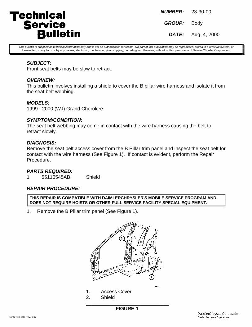
Form TSB-003 Rev. 1.07
NUMBER: 23-30-00
GROUP: Body
DATE: Aug. 4, 2000
SUBJECT:Front seat belts may be slow to retract.
OVERVIEW:This bulletin involves installing a shield to cover the B pillar wire harness and isolate it fromthe seat belt webbing.
MODELS:1999 - 2000 (WJ) Grand Cherokee
SYMPTOM/CONDITION:The seat belt webbing may come in contact with the wire harness causing the belt toretract slowly.
DIAGNOSIS:Remove the seat belt access cover from the B Pillar trim panel and inspect the seat belt forcontact with the wire harness (See Figure 1). If contact is evident, perform the RepairProcedure.
PARTS REQUIRED:1 55116545AB Shield
REPAIR PROCEDURE:
1. Remove the B Pillar trim panel (See Figure 1).
1. Access Cover2. Shield______________________________
FIGURE 1
This bulletin is supplied as technical information only and is not an authorization for repair. No part of this publication may be reproduced, stored in a retrieval system, ortransmitted, in any form or by any means, electronic, mechanical, photocopying, recording, or otherwise, without written permission of DaimlerChrysler Corporation.
THIS REPAIR IS COMPATIBLE WITH DAIMLERCHRYSLER'S MOBILE SERVICE PROGRAM ANDDOES NOT REQUIRE HOISTS OR OTHER FULL SERVICE FACILITY SPECIAL EQUIPMENT.
-2- 23-30-00
2. Install the shield, p/n 55116545AB, into the opening by inserting the tabs one at atime.
3. Install the trim panel
POLICY: Reimbursable within the provisions of the warranty.
TIME ALLOWANCE:Labor Operation No: 23-13-02-93 ................................................................0.4 Hrs.
FAILURE CODE: P8 - New Part

Form TSB-003 Rev. 1.08 February 3, 2000
NUMBER: 23-31-00
GROUP: Body
DATE: Aug. 18, 2000
SUBJECT:Rattle/Chuck In The Second Row Seat When Seat Is In Upright Position
OVERVIEW:This bulletin involves installing revised outboard seat back latches on both right side andleft side second row seats.
MODELS:1998 - 2000 (DN) Durango
NOTE: THIS BULLETIN APPLIES TO VEHICLES EQUIPPED WITH THE 40/20/40SECOND ROW SPLIT BENCH SEAT (SALES CODE CFM).
SYMPTOM/CONDITION:The 40/20/40 second row split bench seat back may chuck or rattle while in the upright andlocked position when going over bumps.
DIAGNOSIS:With the second row seat latched in the upright position, firmly grab the seat back on theupper outboard corner of either 40% portion of the second row seat and push in a fore-aftmotion. If the seat latch rattles when you push the seat back fore and aft, perform theRepair Procedure.
PARTS REQUIRED:1 05018998AB Latch, Second Row Outboard, Right Side1 05019001AB Latch, Second Row Outboard, Left Side
REPAIR PROCEDURE:
1. Tumble the seat forward.2. Remove the screw that secures the outboard latch release handle and remove the
handle.3. Remove the three screws that secure the outboard latch cover and remove the latch
cover.4. Disengage the seat cover hook-and-arrow on the outboard side of the seatback
(Figure 1).
This bulletin is supplied as technical information only and is not an authorization for repair. No part of this publication may be reproduced, stored in a retrieval system, ortransmitted, in any form or by any means, electronic, mechanical, photocopying, recording, or otherwise, without written permission of DaimlerChrysler Corporation.
THIS REPAIR IS COMPATIBLE WITH DAIMLERCHRYSLER'S MOBILE SERVICE PROGRAM ANDDOES NOT REQUIRE HOISTS OR OTHER FULL SERVICE FACILITY SPECIAL EQUIPMENT.

23-31-00 -2-
5. Remove bolts attaching the outboard latch to the seat cushion and seat back frame.6. Disconnect the cable to the outboard latch.7. Connect the cable to the new outboard latch (see Parts Required section).8. Install the new outboard latch onto the seat cushion and seat back frame. Tighten the
bolt located in the round hole first, than the bolts located in the slotted holes (Figure2). Tighten the bolts to 27 N•m (19 ft. lbs.).
FIGURE 11 - SEAT BACK COVER HOOK2 - OUTBOARD LATCH3 - SEAT BACK COVER ARROW
FIGURE 21 - OUTBOARD LATCH SEAT BACK SLOTTED BOLT HOLE2 - OUTBOARD LATCH3 - OUTBOARD LATCH CUSHION SLOTTED BOLT HOLE

-3- 23-31-00
NOTE: THE SEAT MUST BE IN THE FORWARD TUMBLED POSITION PRIOR TOTIGHTENING THE NEW OUTBOARD LATCH. FAILURE TO TIGHTEN THELATCH IN THIS POSITION COULD RESULT IN LOOSENESS BETWEENTHE LATCH AND THE SEAT CUSHION FRAME CAUSING ACHUCK/RATTLE IN THE OUTBOARD LATCH.
9. Engage the seat cover hook-and-arrow on the outboard side of the seatback.10. Install the outboard latch cover and secure it with the three screws.11. Install the outboard latch release handle and secure it with the screw.12. Remove and install the second row outboard latch on the other seat using the
procedure described in Steps 1 through 11.
POLICY: Reimbursable within the provisions of the warranty.
TIME ALLOWANCE:Labor Operation No: 23-41-61-90 ................................................................0.6 Hrs.
FAILURE CODE: P8 - New Part


Form TSB-003 Rev. 1.08 February 3, 2000
NUMBER: 23-32-00 Rev. A
GROUP: Body
DATE: Sept. 22, 2000
THIS BULLETIN SUPERSEDES TECHNICAL SERVICE BULLETIN 23-32-00, DATEDSEPT. 8, 2000, WHICH SHOULD BE REMOVED FROM YOUR FILES. ALLREVISIONS ARE HIGHLIGHTED WITH **ASTERISKS** AND INCLUDE CHANGES TOTHE REPAIR PROCEDURE.
SUBJECT:Quad Seat And 50/50 Rear Bench Seat Rattle Or Groan Sound And/Or Latch Effort
OVERVIEW:This bulletin involves applying MOPAR silicone spray lube to the quad seat and 50/50 rearbench seat latch strikers.
MODELS:2001 (RS) Town & Country/Caravan/Voyager2001 (RG) Chrysler Voyager (International Markets)
SYMPTOM/CONDITION:Some vehicles may exhibit a rattle sound from the quad seat(s) and/or 50/50 rear benchseat(s) and/or a groan sound when the seat(s) are tumbled forward and/or seat(s) may bedifficult to unlatch for tumble or easy entry.
DIAGNOSIS:If the vehicle operator describes any of the above conditions, perform the RepairProcedure.
PARTS REQUIRED:AR 04318070 Lube, MOPAR Silicone Spray
REPAIR PROCEDURE:
1. Move the seat headrest to full down position.2. Using recliner handle on quad seats, or lever #1 on 50/50 rear bench seats, fold seat
back forward until it latches.3. Tumble the seat forward, using easy entry handle on quad seats, or lever #2 on 50/50
rear bench seats.4. Pull the release strap #3 to unlatch the seat from the floor.5. **Smooth the bottom of the seat latch strikers in the floor with sandpaper.6. Spray bottom and top** of the seat latch strikers (4 for each seat) with MOPAR
silicone spray lube, p/n 04318070.7. Install the seat.8. Repeat steps 1 through 7 on all remaining quad and 50/50 seats.
This bulletin is supplied as technical information only and is not an authorization for repair. No part of this publication may be reproduced, stored in a retrieval system, ortransmitted, in any form or by any means, electronic, mechanical, photocopying, recording, or otherwise, without written permission of DaimlerChrysler Corporation.
THIS REPAIR IS COMPATIBLE WITH DAIMLERCHRYSLER'S MOBILE SERVICE PROGRAM ANDDOES NOT REQUIRE HOISTS OR OTHER FULL SERVICE FACILITY SPECIAL EQUIPMENT.
23-32-00 Rev. A -2-
POLICY: Reimbursable within the provisions of the warranty.
TIME ALLOWANCE:Labor Operation No: 23-13-38-90 ...............................................................0.2 Hrs.
FAILURE CODE: 68 - Noisy
Form TSB-003 Rev. 1.08 February 3, 2000
NUMBER: 23-33-00
GROUP: Body
DATE: Sep. 15, 2000
SUBJECT:Sounds Associated With Power Sliding Door Operation
OVERVIEW:This bulletin involves applying Door-Ease to areas of the power sliding door tracks.
MODELS:2001 (RS) Town & Country/Caravan/Voyager2001 (RG) Chrysler Voyager (International Markets)
SYMPTOM/CONDITION:Some vehicles may exhibit a growling sound when being slid and/or a ratcheting/creakingsound when the Power Sliding Door (PSD) is cinching closed.
DIAGNOSIS:Open and close the PSD manually. If a growl sound is heard coming from the lower trackarea, perform the Repair Procedure. Open and close the PSD using the power feature, ifa ratcheting/creaking sound is heard as the PSD cinches closed, perform the RepairProcedure.
PARTS REQUIRED:1 NPN Door-Ease
REPAIR PROCEDURE:
1. Wipe load-bearing flange (Figure1) clean over whole length of the lower hinge trackwith a clean damp cloth. Let dry.
This bulletin is supplied as technical information only and is not an authorization for repair. No part of this publication may be reproduced, stored in a retrieval system, ortransmitted, in any form or by any means, electronic, mechanical, photocopying, recording, or otherwise, without written permission of DaimlerChrysler Corporation.
THIS REPAIR IS COMPATIBLE WITH DAIMLERCHRYSLER'S MOBILE SERVICE PROGRAM ANDDOES NOT REQUIRE HOISTS OR OTHER FULL SERVICE FACILITY SPECIAL EQUIPMENT.

Form TSB-003 Rev. 1.08 February 3, 2000
23-33-00 -2-
2. Apply a generous amount of Door-Ease stick lubricant on the load-bearing flange ofthe lower hinge track and rub over whole length. Presence of Door-Ease on sidewallof track and/or small down-turned flange is ok.
3. Using thumb and/or finger(s), work the just applied Door-Ease around on the load-bearing flange to ensure even, consistent coverage.
4. Inspect to verify there is 100% coverage of load bearing flange with Door-Ease. Ifnot, apply more Door-Ease and repeat step 3.
5. Wipe clean the area of the center track that is cross-hatched and shaded in Figure 2with a clean damp cloth. Let dry.
FIGURE 1
1. 100% COVERAGE WITH DOOR-EASE ON THE LOAD BEARINGSURFACE IS REQUIRED
2. DOOR-EASE ON SIDEWALL IS OK BUT NOT REQUIRED3. DOOR-EASE ON SMALL DOWN TURNED FLANGE IS OK BUT NOT
REQUIRED
FIGURE 2
1. 100% COVERAGE WITH DOOR-EASE REQUIRED2. DOOR-EASE IS PERMISSIBLE IN THIS AREA
NOTE: PRESENCE OF DOOR EASE IS UNACCEPTABLE OUTSIDE OFAREAS 1 AND 2.

-3- 23-33-00
6. Apply Door-Ease stick lubricant to the center hinge track area shown as shaded inFigure 2.
7. Using thumb and/or finger(s), work the just applied Door-Ease around on the load-bearing flange to ensure even, consistent coverage in the shaded area
8. Inspect to verify there is 100% coverage of load bearing flange with Door-Ease. Ifnot, apply more Door-Ease and repeat step 6
9. Open and close the PSD manually and with the power feature to verify repair.
POLICY: Reimbursable within the provisions of the warranty.
TIME ALLOWANCE:Labor Operation No: 23-40-25-90 ................................................................0.2 Hrs.
FAILURE CODE: 68 - Noisy


NUMBER: 23-035-00 Rev. B
GROUP: Body
DATE: Dec. 29, 2000
This bulletin is supplied as technical information only and is not an authorization for repair. No part of this publication may be reproduced, stored in a retreival system,or transmitted, in any form or by any means, electronic, mechanical, photocopying, or otherwise, without written permission of DaimlerChrysler Corporation.
THIS BULLETIN SUPERSEDES TECHNICAL SERVICE BULLETIN 23-035-00REV. A, DATED OCT. 27, 2000, WHICH SHOULD BE REMOVED FROMYOUR FILES. THIS IS A COMPLETE REVISION AND NO **ASTERISKS**HAVE BEEN USED TO HIGHLIGHT CHANGES.
SUBJECT:Power Mode Closes Lift Gate But Does Not Open The Lift Gate
NOTE: THIS BULLETIN SHOULD BE PERFORMED ON ALL IN STOCK VEHICLESBUILT BEFORE NOVEMBER 13, 2000 (MDH1113XX).
OVERVIEW:This bulletin involves flashing the Power Lift Gate (PLG) module and resettingobstacle detection values. Adjusting the lift gate striker and/or installing liftgate overslam bumper shims may also be required.
MODELS:
2001 (RS) Town & Country/Caravan/Voyager
2001 (RG) Chrysler Voyager (International Markets)
SYMPTOM/CONDITION:The PLG functions in the power closing mode but not the opening mode. The lift gateis not flush with the tail lights. Low seal load prevents the lift gate from "popping off"and moving the lift gate latch out of the primary latching position.
DIAGNOSIS:DIAGNOSIS 1:Power operate the lift gate to open with the Remote Keyless Entry (RKE) Fobor button in the overhead console. If the lift gate does not move out of theprimary latching position, perform Repair Procedure 1.DIAGNOSIS 2:Inspect the lift gate for flushness to the body above and below the tail lamps. If the lift gate isunderflush to the body above the tail lamp and underflush or flush below the tail lamp, go toProcedure 2A. If the lift gate is flush or overflush to the body above and below the tail lamp,go to Procedure 2B. If the lift gate is flush or underflush to the body above the tail lamps andover flush below the tail lamp AND the difference is more than 5mm, go to Procedure 2C.

23-035-00 Rev. B -2-
PARTS REQUIRED:
Qty. Part No. Description
AR (6) 05020315AA Shims, Lift Gate Overslam Bumper
EQUIPMENT REQUIRED:
CH6000 Scan Tool, DRBIII® operating at CIS CD2073 or higherCH7035 General Purpose Interface Bus Cable (GPIB)
CH700/7001 J1962 Cable
MDS2
NOTE: THE MDS2 AND DRB III ® ARE REQUIRED TO PERFORM PART OF THISREPAIR. THE MDS2 SYSTEM MUST BE OPERATING WITH CIS CD2073 OR HIGHER.
REPAIR PROCEDURE:PROCEDURE 1:1. Log onto the MDS2 System.2. Connect the MDS2 (Mopar Diagnostic System) and DRB III® (Scan Tool)
to the vehicle and switch the ignition to “ON”.
NOTE: AUTO CONNECTION WILL OCCUR ONCE THE DRB III ®, MDS2 AND VEHICLEESTABLISH COMMUNICATION. THE "CANNOT READ VIN FROM DRB III ®" MESSAGE(ON THE MDS2) WILL BE REPLACED BY THE VEHICLE VIN. PRESS THE "OK"BUTTON ON THE MDS2 TO REQUEST A MDS2 SESSION FOR THE VEHICLE VININDICATED. PRESS THE "OK" BUTTON WHEN ASKED TO BEGIN SESSION.
3. Push the FLASH tab on the MDS2.4. Select READ PART NUMBERS FROM VEHICLE and click SHOW
UPDATES on the MDS2.
NOTE: A MESSAGE MAY APPEAR (AFTER STEP 3 OR 4) THAT INDICATES NOUPDATES ARE AVAILABLE. IF THIS OCCURS, MAKE SURE YOUR DIAGNOSTICEQUIPMENT IS OPERATING AT THE LATEST SOFTWARE LEVEL AS LISTEDEARLIER IN THIS BULLETIN. IF THE LATEST SOFTWARE IS INSTALLED, ANDNO UPDATES ARE AVAILABLE, ANOTHER VEHICLE CONDITION EXISTSTHAT WILL REQUIRE FURTHER INVESTIGATION.
5. Select the new software part number with the light pen and clickUPDATE CONTROLLER SOFTWARE.
6. The MDS2 and DRB III® will prompt for any operator action needed duringthe remainder of the reprogramming process.
NOTE: NOTE: INSTRUCTIONS ON THE DRB III ® SCREEN WILL ASK FOR THEIGNITION KEY TO BE TURNED TO THE “LOCK” POSITION, THIS MUST BEDONE WITHIN 15 SECONDS. SHORTLY AFTER THE IGNITION KEY IS PLACEDIN THE “LOCK” POSITION, REPROGRAMING WILL BEGIN. THE IGNITION KEYMUST REMAIN IN THE “LOCK” POSITION UNTIL THE DRB III ® SCREEN ASKSFOR THE KEY TO BE TURNED TO THE “ON” POSITION.
-3- 23-035-00 Rev. B
7. Cycle the PLG open/close three times.8. If the flash procedure fails to correct the lift gate failure to move out of the
primary latching position, go to DIAGNOSIS 2.
PROCEDURE 2A:1. Add three lift gate bumper shims, p/n 05020315AA, behind the rubber
bumper on each side of the lift gate opening.2. Add or subtract lift gate bumper shims as required to achieve a consistent fit side to side.3. Power operate the PLG to open and then close with the RKE Fob or button
in the overhead console to verify proper operation.4. Reset the PLG module obstacle detection values by cycling the PLG three
times or by connecting the DRBIII® and selecting Standalone/1998–2001Diagnostics/Body/Power Lift Gate/Misc/Reset Module.
PROCEDURE 2B:1. Adjust the lift gate striker forward (in car) in 2mm increments until "pop off" is achieved. Do
not let the lift gate become more then 3mm underflush to the body above the tail lamps.2. Power operate the PLG to open and then close with the RKE Fob or button in the overhead
console. Perform Procedure A if the lift gate has moved to 3mm or more underflush tothe body above the tail lamps without the lift gate opening in the power mode.
3. Reset the PLG module obstacle detection values by cycling the PLG threetimes or by connecting the DRBIII® and selecting Standalone/1998–2001Diagnostics/Body/Power Lift Gate/Misc/Reset Module.
PROCEDURE 2C:1. Move the striker rearward 2mm and remeasure flushness above and below the tail lamps.
Flushness should improve above the tail lamps with no change below the tail lamps.2. Power operate the PLG to open and then close with the RKE Fob or
button in the overhead console.3. Add three lift gate bumper shims, p/n 05020315AA, behind the rubber
bumper on each side of the lift gate opening.4. Add or subtract lift gate bumper shims as required to achieve a consistent fit side
to side. The lift gate will remain overflush below the tail lamps.5. Reset the PLG module obstacle detection values by cycling the PLG three
times or by connecting the DRBIII® and selecting Standalone/1998–2001Diagnostics/Body/Power Lift Gate/Misc/Reset Module.
POLICY:Reimbursable within the provisions of the warranty.
TIME ALLOWANCE:
Labor Operation No:
08-19-31-90 Flash PLG Module 0.3 Hrs
23-41-43-99 Adjust Lift Gate, 0.3 Hrs.
FAILURE CODE:
FM Flash Module
XX Service Adjustment

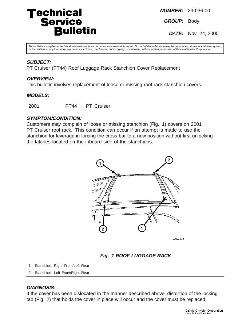
NUMBER: 23-036-00
GROUP: Body
DATE: Nov. 24, 2000
This bulletin is supplied as technical information only and is not an authorization for repair. No part of this publication may be reproduced, stored in a retreival system,or transmitted, in any form or by any means, electronic, mechanical, photocopying, or otherwise, without written permission of DaimlerChrysler Corporation.
SUBJECT:PT Cruiser (PT44) Roof Luggage Rack Stanchion Cover Replacement
OVERVIEW:This bulletin involves replacement of loose or missing roof rack stanchion covers.
MODELS:
2001 PT44 PT Cruiser
SYMPTOM/CONDITION:Customers may complain of loose or missing stanchion (Fig. 1) covers on 2001PT Cruiser roof rack. This condition can occur if an attempt is made to use thestanchion for leverage in forcing the cross bar to a new position without first unlockingthe latches located on the inboard side of the stanchions.
Fig. 1 ROOF LUGGAGE RACK
1 - Stanchion, Right Front/Left Rear
2 - Stanchion, Left Front/Right Rear
DIAGNOSIS:If the cover has been dislocated in the manner described above, distortion of the lockingtab (Fig. 2) that holds the cover in place will occur and the cover must be replaced.

23-036-00 -2-
Fig. 2 STANCHION COVER LOCKING TAB
1 - Locking Tab
Replacing the cover will involve the use of a kit (either left or right) that contains anew cover and special high-strength-adhesive strips (Fig. 3).
Fig. 3 STANCHION COVER KITS
1 - Cover, Left Front/Right Rear
2 - Adhesive Strips (two each)
3 - Cover, Right Front/Left Rear

-3- 23-036-00
PARTS REQUIRED:
Qty. Part No. Description
AR (1) 05072124AA Stanchion Cover Kit, Right Front/Left Rear
AR (1) 05072125AA Stanchion Cover Kit, Left Front/Right Rear
REPAIR PROCEDURE:
THIS REPAIR IS COMPATIBLE WITH DAIMLERCHRYSLER’S MOBILESERVICE PROGRAM AND DOES NOT REQUIRE HOISTS OR OTHERFULL SERVICE FACILITY SPECIAL EQUIPMENT.
1. Remove the old stanchion cover and clean the contact surfaces on the stanchionand new stanchion cover with isopropyl alcohol (Fig. 4).
Fig. 4 CLEAN SURFACES
1 - Clean Contact Surfaces
2. Remove one of the liners with adhesive from the backing strip (Fig. 5). Make sureto hold the liner by the edge that has no adhesive on it (Fig. 6).
NOTE: TWO ADHESIVE STRIPS ARE SUPPLIED WITH EACH KIT, BUT ONLY ONEIS REQUIRED TO COMPLETE THE REPAIR. THE SECOND ADHESIVE STRIP ISPROVIDED IN CASE THERE IS A PROBLEM WITH THE FIRST ATTEMPT.

23-036-00 -4-
Fig. 5 ADHESIVE
1 - Adhesive Location
Fig. 6 REMOVE LINER
1 - Edge With No Adhesive
3. Place the tape onto the contact surface of the stanchion and pullthe liner off the adhesive (Fig. 7).

-5- 23-036-00
Fig. 7 APPLY ADHESIVE
1 - Apply Adhesive Here
4. Slide the stanchion cover onto the stanchion, being careful to keep the topcorner lifted enough to prevent adhesive from prematurely sticking to thecover before it is in the correct position (Fig. 8).
NOTE: WHEN THE COVER IS IN THE PROPER POSITION, YOU CAN HEARTHE LOCKING TAB SNAP INTO PLACE.
Fig. 8 REPLACE COVER
5. Once the cover is in the proper position, apply thumb pressure to the cover in the regionabove the adhesive contact point for approximately 30 seconds (Fig. 9).

23-036-00 -6-
Fig. 9 APPLY THUMB PRESSURE
POLICY:Reimbursable within the provisions of the warranty.
TIME ALLOWANCE:
Labor Operation No: Description Amount
23-06-10-92 Cover, Luggage Rack Stanchion – ReplaceUp To Three Covers
0.2 Hrs.
23-06-10-93 Cover, Luggage Rack Stanchion –Replace All Covers
0.3 Hrs.
FAILURE CODE:
P8 New Part

NUMBER: 23-37-00
GROUP: Body
DATE: Sept. 29, 2000
This bulletin is supplied as technical information only and is not an authorization for repair. No part of this publication may be reproduced, stored in a retreival system,or transmitted, in any form or by any means, electronic, mechanical, photocopying, or otherwise, without written permission of DaimlerChrysler Corporation.
SUBJECT:Quad Seat Cupholder to Floormat Interference
MODELS:
2001 (RS) Town & Country/ Caravan/Voyager
2001 (RG) Chrysler Voyager (International Markets)
DISCUSSION:The RS Quad Seat Cupholder has two modes of operation. When closed, thecupholder travels with the quad seat assembly as the seat is tumbled forward foraccess to the third-row seat or for removal from the vehicle. When opened and inuse, the cupholder does not travel with the seat as the seat is tumbled forward,but remains level to minimize spillage of any contents.
Because of the innovative function of the cupholder, the user should beaware of the following important points:• Proper operation of the cupholder is sensitive to the thickness of the floor mat. If the floormat is removed or a thicker mat is used, some cupholder function may be reduced.
• Operating the vehicle without the floor mats in place may increase the likelihoodof Buzz, Squeak and Rattles (BSR’s) in the cupholder area.
• Because the cupholder rests on the floor mat, the cupholders should be closedand the quad seats should be tumbled forward (to the easy entry position)before the floor mat is adjusted, removed or replaced.
POLICY:Information Only


NUMBER: 23–038–00
GROUP: Body
DATE: Oct. 13, 2000
This bulletin is supplied as technical information only and is not an authorization for repair. No part of this publication may be reproduced, stored in a retreival system,or transmitted, in any form or by any means, electronic, mechanical, photocopying, or otherwise, without written permission of DaimlerChrysler Corporation.
SUBJECT:Seat Belt Turning Loop Cover Repair
OVERVIEW:This bulletin involves repairing the seat belt turning loop cover instead of replacing the seatbelt assembly when the cover hinge has broken.
MODELS:
1999 - 2000 WJ Grand Cherokee
1999 - 2000 LH Concorde, Intrepid, LHS, 300M
SYMPTOM/CONDITION:The cover on the seat belt turning loop may break at the plastic hinge. A Repair Procedurehas been developed to replace the cover rather that replacing the seat belt assembly.
DIAGNOSIS/REPAIR PROCEDURES:If the seat belt turning loop cover has broken and separated from the base, perform the RepairProcedure.
PARTS REQUIRED:
AR 5HK91LAZaa Cover - WJ/LH Agate
AR 5HK91RK5aa Cover - WJ/LH Camel
AR 5HK91WL5aa Cover - WJ/LH Taupe
AR 5HK91XT5aa Cover - WJ/LH Sandstone
AR 5HK91XDVaa Cover - LH Dark Slate
AR 5HK91TL2aa Cover - LH Light Taupe
AR 5HK91MF1aa Cover - LH Light Neutral
AR 55116563aa Cover - Export -Black
REPAIR PROCEDURE:
THIS REPAIR IS COMPATIBLE WITH DAIMLERCHRYSLER’S MOBILESERVICE PROGRAM AND DOES NOT REQUIRE HOISTS OR OTHERFULL SERVICE FACILITY SPECIAL EQUIPMENT.
1. Remove the cover from the base of the appropriate part listed above and file the hingeflush with the cover(Fig. 1).

23–038–00 -2-
2. Apply a coating of adhesive promoter such as 3M p/n 06396 or equivalent, to the inside ofthe cover in the two areas where the foam tape will be applied, and to the turning loop(Fig.1).
NOTE: Adhesion promoter must be used to assure proper adhesion between the foamtape and the plastic parts.
Fig. 1 TURNING LOOP
1 - Hinge
2 - Foam Tape
3. Cut four 3/4 inch pieces of double side adhesive foam emblem tape, such as 3M p/n06382 or equivalent. Remove the protective film and apply two pieces of tape to eachside of the cover as shown(Fig. 1).
4. Install the cover on to the turning loop by rolling it on from the top and snapping the re-tainer into the slot.
POLICY:Reimbursable within the provisions of the warranty.
TIME ALLOWANCE:
Labor Operation No: 23-13-10-90 0.2 Hrs.
FAILURE CODE: Could be one or more
P8 New Part

NUMBER: 23-039-00
GROUP: Body
DATE: Oct. 20, 2000
This bulletin is supplied as technical information only and is not an authorization for repair. No part of this publication may be reproduced, stored in a retreival system,or transmitted, in any form or by any means, electronic, mechanical, photocopying, or otherwise, without written permission of DaimlerChrysler Corporation.
THIS BULLETIN SUPERCEDES TECHNICAL SERVICE BULLETIN 23-11-95, DATEDMARCH 10, 1995, WHICH SHOULD BE REMOVED FROM YOUR FILES AND NOTEDIN THE 1995 TECHNICAL SERVICE BULLETIN MANUAL (PUBLICATION NO.81-699-96084). ALL REVISIONS ARE HIGHLIGHTED WITH **ASTERISKS** ANDINCLUDE ADDITIONAL MODEL YEARS AND PART NUMBER CHANGE.
SUBJECT:Door Glass Lift Plate Service
OVERVIEW:This bulletin involves replacing door glass lift plates.
MODELS:
1993 - **2001** (LH) Concorde/Intrepid/LHS/New Yorker/Vision/300M
DISCUSSION:Door glass lift plates are now serviced separately from the glass. Anytime the door glass isintact and the lift plate(s) is worn or damaged, perform the repair procedure.
PARTS REQUIRED:
AR(2) **04878907AA** Lift Plate, Door Glass
AR NPN Urethane Windshield Sealer (3M p/n08609 or Equivalent)
REPAIR PROCEDURE:
THIS REPAIR IS COMPATIBLE WITH DAIMLERCHRYSLER’S MOBILESERVICE PROGRAM AND DOES NOT REQUIRE HOISTS OR OTHERFULL SERVICE FACILITY SPECIAL EQUIPMENT.
1. Remove door trim panel and upper trim retainer channel.2. Connect power window switch and lower window to 50 mm (2 in.)3. Loosen screws holding regulator roller channel to glass.4. Slide roller channel rearward to allow screw heads to pass through key slots in channel.5. Separate glass from roller channel.6. Raise glass upward and out of opening at top of door.7. Mark location of liftplate(s) on glass.8. Heat lift plate with propane torch or heat gun to soften urethane and pry lift plate from
glass by inserting flat screw driver between edge of glass and plate.

23-039-00 -2-
9. Clean any remaining urethane from glass surface.10. Apply urethane windshield sealer to channel in new lift plate.11. Push and/or tap plate onto glass in the previously marked position.12. Allow urethane to harden for at least 12 hours before operating window (longer times are
required if temperature is below 50 degrees F.).
NOTE: URETHANE SHOULD SET FOR 1 HOUR BEFORE HANDLING/INSTALLINGTHE GLASS. THE REMAINING CURE TIME CAN BE ACHIEVED IF THE WINDOW ISINSTALLED AND LOCKED IN THE UP POSITION FOR THE SPECIFIED TIME. THISWILL ALLOW THE VEHICLE TO BE RETURNED TO THE CUSTOMER WITH THEWINDOW HANDLE OR SWITCH TAPED TO PREVENT USE.
13. Reverse removal instructions to install glass in door.
POLICY:Reimbursible within the provisions of the warranty.
TIME ALLOWANCE:
Labor Operation No:
23-30-10-92 Right Front Glass 1.0 Hrs.
23-30-10-93 Left Front Glass 1.0 Hrs.
23-30-10-94 Right Rear Glass 1.0 Hrs.
23-30-10-95 Left Rear Glass 1.0 Hrs.
FAILURE CODE:
P8 New Part

NUMBER: 23-040-00
GROUP: Body
DATE: Oct. 27, 2000
This bulletin is supplied as technical information only and is not an authorization for repair. No part of this publication may be reproduced, stored in a retreival system,or transmitted, in any form or by any means, electronic, mechanical, photocopying, or otherwise, without written permission of DaimlerChrysler Corporation.
SUBJECT:Rear Door Lock(s) Do not Operate Properly
OVERVIEW:This bulletin involves removing the rear door lock knob rod foam anti-rattle pad and installingan anti-rattle silencer disk.
MODELS:
1998 - 2000 (DN) Durango
SYMPTOM/CONDITION:Rear door lock knob linkage sticks/binds causing the rear door latch lock mechanism to notfunction properly. Customers may indicate that they are not able to lock or unlock their reardoor(s).
DIAGNOSIS:Attempt to operate the affected rear door lock mechanism by manually pulling up/pushingdown on the lock knob. If the lock mechanism fails to operate or binds when the knob ispulled up/pushed down, perform the Repair Procedure.
PARTS REQUIRED:
Qty. Part No. Description
AR (2) 55034246 Disc, Anti-Rattle Silencer
REPAIR PROCEDURE:
THIS REPAIR IS COMPATIBLE WITH DAIMLERCHRYSLER’S MOBILESERVICE PROGRAM AND DOES NOT REQUIRE HOISTS OR OTHERFULL SERVICE FACILITY SPECIAL EQUIPMENT.
1. Release door latch and open door.2. Roll window down.3. Pull upper trim extension outward to disengage from rear door (Fig. 1).
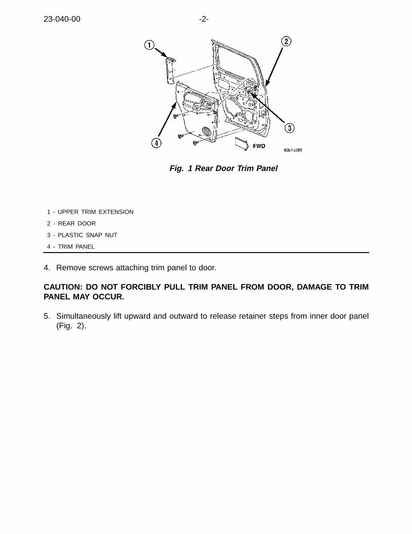
23-040-00 -2-
Fig. 1 Rear Door Trim Panel
1 - UPPER TRIM EXTENSION
2 - REAR DOOR
3 - PLASTIC SNAP NUT
4 - TRIM PANEL
4. Remove screws attaching trim panel to door.
CAUTION: DO NOT FORCIBLY PULL TRIM PANEL FROM DOOR, DAMAGE TO TRIMPANEL MAY OCCUR.
5. Simultaneously lift upward and outward to release retainer steps from inner door panel(Fig. 2).

-3- 23-040-00
Fig. 2 Trim Panel Retainer
1 - TRIM PANEL
2 - RETAINER STEP
3 - INNER DOOR PANEL
6. Disengage inside handle linkage rod from inside handle.7. Disconnect power window/lock harness connector (Fig. 3).
Fig. 3 Power Window Lock Connector
1 - TRIM PANEL
2 - INSIDE HANDLE LATCH ROD
3 - POWER WINDOW/LOCK CONNECTOR
8. Separate door trim panel from vehicle.9. Disassemble the lock knob/rod assembly from the clip at its lower end (Fig. 4).

23-040-00 -4-
Fig. 4 LOCK KNOB REMOVAL
1 - LOCK KNOB ATTACHING CLIP
2 - LOCK KNOB ROD
NOTE: BEFORE PROCEEDING, VERIFY THE OPERATION OF THE LOCK MECHANISMOF THE LATCH. IF THE LOCK MECHANISM OF THE LATCH STILL BINDS/STICKS,LATCH REPLACEMENT MAY BE REQUIRED.
10. Remove the foam anti-rattle pad from the door inner panel (Fig. 5).
NOTE: MAKE SURE THAT ALL OF THE FOAM IS REMOVED FROM THE DOOR INNERPANEL. IN ADDITION, A COMPLETE INSPECTION OF THE LOCK ROD ASSEMBLY,LATCH ASSEMBLY, AND THE DOOR INNER PANEL SHOULD BE PERFORMED TO EN-SURE THAT ANY LOOSE FOAM IS REMOVED FROM THE DOOR PANEL.

-5- 23-040-00
Fig. 5 FOAM REMOVAL
1 - FOAM ANTI-RATTLE PAD
2 - INNER DOOR WATERSHIELD
11. Using a sharp knife or scissors, enlarge the opening which the lock knob rod extendsthrough the door watershield, an additional 13 mm (1/2 in.) closer to the lock knob at-taching clip. This will make the bottom edge of the opening even with the top verticaledge of the lock knob rod attaching clip (Fig. 6).
Fig. 6 WATER SHIELD CUTOUT
1 - CUT WATERSHIELD AS SHOWN
2 - INNER DOOR WATERSHIELD

23-040-00 -6-
12. With the protrusion of the anti-rattle silencer disc p/n 55034246 facing downward, slidethe anti-rattle silencer disc over the lower end of the lock knob rod. Position the anti-rattledisc approximately 5 mm (0.2 in.) past the second bend of the lock knob rod (Fig. 7).
Fig. 7 ANTI-RATTLE SILENCER DISC POSITIONING
1 - LOCK KNOB ROD
2 - ANTI-RATTLE SILENCER DISC
3 - LOCK KNOB ROD FIRST BEND
4 - LOCK KNOB ROD SECOND BEND
13. Attach the lock knob rod to its attaching clip.
NOTE: MAKE SURE THE ANTI-RATTLE SILENCER DISC BENDS UPWARD AGAINSTTHE SHEET METAL OF THE INNER DOOR PANEL (Fig. 8).

-7- 23-040-00
Fig. 8 ANTI-RATTLE SILENCER DISC INSTALLATION
1 - LOCK KNOB
2 - ANTI-RATTLE DISC POSITION
3 - LOCK KNOB ROD
14. Install upper trim extension on rear door.15. Position trim panel at door.16. Engage harness connector for power window/lock.17. Engage inside handle linkage rod to inside handle.18. Align trim panel retainer steps with inner door panel and slide trim panel into place.19. Install screws attaching trim panel to door.20. Attach the upper trim extension onto the rear door.
POLICY:Reimbursable within the provisions of the warranty.
TIME ALLOWANCE:
Labor Operation No:
23-41-19-90 Install Anti-Rattle Silencer Disk, One Side 0.3 Hrs.
FAILURE CODE:
P8 New Part

NUMBER: 23-042-00
GROUP: Body
DATE: Nov. 3, 2000
This bulletin is supplied as technical information only and is not an authorization for repair. No part of this publication may be reproduced, stored in a retreival system,or transmitted, in any form or by any means, electronic, mechanical, photocopying, or otherwise, without written permission of DaimlerChrysler Corporation.
SUBJECT:Sliding Door Power Lock Actuator Chatter Sound
OVERVIEW:This bulletin involves installing a rubber O-ring on the sliding door lock lever tab toeliminate the plunger lifting away from the lock lever when in the lock position.
MODELS:
1996 - 2000 (NS) Town & Country/Caravan/Voyager
1996 - 2000 (GS) Chrysler Voyager (International Markets)
SYMPTOM/CONDITION:A chatter sound may be heard coming from the sliding door power lock actuator(s)when the power lock feature is repeatedly activated.
DIAGNOSIS:Use the power door lock switch to perform an unlock - lock - lock cycle, repeatthe cycle three times, if a chatter sound is heard at one or both of the slidingdoor actuators, perform the Repair Procedure.
NOTE: REPEATING THE TEST MORE THAN 3 TIMES MAY TRIP THE POSITIVETEMPERATURE COEFFICIENT (PTC) CIRCUIT AND CAUSE THE CHATTER SOUND;CHATTER DUE TO TRIPPING OF THE PTC IS NOT CONSIDERED A FAILURE. IF THEPTC CIRCUIT HAS TRIPPED, WAIT ONE HOUR BEFORE RETRYING THE DIAGNOSIS.
PARTS REQUIRED:
Qty. Part No. Description
AR (2) 05072507AA Silencer Kit, Power Door Lock Actuator Includes:O-ring and Grommet
REPAIR PROCEDURE:
THIS REPAIR IS COMPATIBLE WITH DAIMLERCHRYSLER’S MOBILESERVICE PROGRAM AND DOES NOT REQUIRE HOISTS OR OTHERFULL SERVICE FACILITY SPECIAL EQUIPMENT.
1. Remove the sliding door interior trim panel using the procedure outlined onpage 23-52 of the 2000 Town & Country/Caravan/Voyager Service Manual(Publication No. 81-370-0005 and available on MDS2).
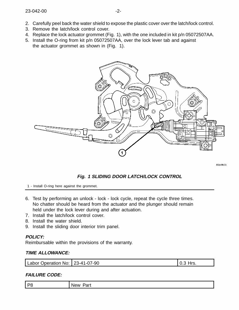
23-042-00 -2-
2. Carefully peel back the water shield to expose the plastic cover over the latch/lock control.3. Remove the latch/lock control cover.4. Replace the lock actuator grommet (Fig. 1), with the one included in kit p/n 05072507AA.5. Install the O-ring from kit p/n 05072507AA, over the lock lever tab and against
the actuator grommet as shown in (Fig. 1).
Fig. 1 SLIDING DOOR LATCH/LOCK CONTROL
1 - Install O-ring here against the grommet.
6. Test by performing an unlock - lock - lock cycle, repeat the cycle three times.No chatter should be heard from the actuator and the plunger should remainheld under the lock lever during and after actuation.
7. Install the latch/lock control cover.8. Install the water shield.9. Install the sliding door interior trim panel.
POLICY:Reimbursable within the provisions of the warranty.
TIME ALLOWANCE:
Labor Operation No: 23-41-07-90 0.3 Hrs.
FAILURE CODE:
P8 New Part
NUMBER: 23–043–00
GROUP: Body
DATE: Dec. 15, 2000
This bulletin is supplied as technical information only and is not an authorization for repair. No part of this publication may be reproduced, stored in a retreival system,or transmitted, in any form or by any means, electronic, mechanical, photocopying, or otherwise, without written permission of DaimlerChrysler Corporation.
SUBJECT:Sunroof Itching/Squeak Sound
OVERVIEW:This bulletin involves cleaning the sunroof seal and sealing area andapplying weatherstrip lubricant to the seal.
MODELS:
2001 (ST) Sebring/Stratus Coupe
SYMPTOM/CONDITION:Some vehicles may exhibit an itching type sound or light squeak that originatesfrom the sunroof seal. Sometimes this sound may seem like it is comingfrom the instrument panel or “A” pillar.
DIAGNOSIS/REPAIR PROCEDURES:Verify the sound by driving the vehicle over a moderately rough road surface. When thesound is heard, open the sunroof to determine if the sound disappears. If the sounddisappears when the sunroof is opened, perform the Repair Procedure.
PARTS REQUIRED:
Qty. Part No. Description
AR(1) 04773427 Lubricant, Weatherstrip
REPAIR PROCEDURE:
THIS REPAIR IS COMPATIBLE WITH DAIMLERCHRYSLER’S MOBILESERVICE PROGRAM AND DOES NOT REQUIRE HOISTS OR OTHERFULL SERVICE FACILITY SPECIAL EQUIPMENT.
1. Open the sunroof to approximately the 1/3 open position.2. Using a damp cloth, wipe all accessible areas of the sunroof glass seal to remove any dirt.3. Wipe the entire perimeter of the sunroof body opening (seal contact area)
with a damp cloth to remove any dirt.4. Apply a light coat of Weatherstrip Lubricant p/n 04773427 to the glass seal.5. Open the sunroof fully and repeat steps 2 through 4 for any areas that
were not accessible from step 1.
23–043–00 -2-
POLICY:Reimbursable within the provisions of the warranty.
TIME ALLOWANCE:
Labor Operation No: 23-51-72-91 0.2
FAILURE CODE:
XX Service Adjustment

NUMBER: 23-044-00
GROUP: Body
DATE: December 15, 2000
This bulletin is supplied as technical information only and is not an authorization for repair. No part of this publication may be reproduced, stored in a retreival system,or transmitted, in any form or by any means, electronic, mechanical, photocopying, or otherwise, without written permission of DaimlerChrysler Corporation.
SUBJECT:Seat Back Rattle
OVERVIEW:This bulletin involves replacement of both front seat back pivot bolts and bushingson vehicles built prior to 07-14-00 (MDH 0714XX).
MODELS:
2001 (PL) Neon
SYMPTOM/CONDITION:The front seat back may rattle due to extra shoulder length on the seat back pivot bolt.
PARTS REQUIRED:
Qty. Part No. Description
2 05017780AA Bolt
2 04680045 Bushing
REPAIR PROCEDURE:
THIS REPAIR IS COMPATIBLE WITH DAIMLERCHRYSLER’S MOBILESERVICE PROGRAM AND DOES NOT REQUIRE HOISTS OR OTHERFULL SERVICE FACILITY SPECIAL EQUIPMENT.
1. Using the procedures provided under the Service Information tab of MDS2, orthe information on page 23 – 107 of the 2001 Neon Service Manual (PublicationNo. 81–270–1025), remove either of the front seats.
2. Remove the seat back pivot bolt (using a 10 mm socket/wrench) (Fig. 1).

23-044-00 -2-
Fig. 1 SEAT BACK PIVOT BOLT
1 - Pivot Bolt
NOTE: IF NECESSARY, MOVE THE SEAT BACK SIDE FACING TRIM AWAY FROMTHE BOLT AREA ENOUGH TO ALLOW ACCESS TO THE BOLT HEAD.
3. Remove the rubber bushing that surrounded the bolt (Fig. 2).
Fig. 2 PIVOT BOLT BUSHING
1 - Bushing
4. Install the new bushing (p/n 04680045). Be sure to orient the bushing withthe smaller diameter lip toward the center of the seat, and the larger diameterlip toward the pivot bolt head/washer (Fig. 3).

-3- 23-044-00
Fig. 3 BUSHING ORIENTATION
1 - Large Diameter Lip
2 - Small Diameter Lip
5. Install the new pivot bolt (p/n 05017780AA) and tighten to 28 Nm (21 ft. lbs.) torque.6. Install the seat per the procedures provided under the Service Information
tab of MDS2, or the information on page 23 – 107 of the 2001 Neon ServiceManual (Publication No. 81–270–1025).
NOTE: THIS PROCEDURE MUST BE COMPLETED ON BOTH FRONT SEATS.
POLICY:Reimbursable within the provisions of the warranty.
TIME ALLOWANCE:
Labor Operation No: 23-13-55-94 0.4
FAILURE CODE:
P8 New Part

NUMBER: 23-045-00
GROUP: Body
DATE: Dec. 29, 2000
This bulletin is supplied as technical information only and is not an authorization for repair. No part of this publication may be reproduced, stored in a retreival system,or transmitted, in any form or by any means, electronic, mechanical, photocopying, or otherwise, without written permission of DaimlerChrysler Corporation.
SUBJECT:Two Passenger Bench Seat Child Seat Anchor And Tether Wires Surface Rusted
OVERVIEW:This bulletin involves removing the two passenger bench seat from the vehicle, separatingthe seat back from the seat bottom and painting the child seat anchor and tether wires
MODELS:
2001 (RS) Town & Country/Voyager/Caravan
NOTE: THIS BULLETIN APPLIES TO VEHICLES BUILT AT WINDSORPRIOR TO OCTOBER 12, 2000 AND VEHICLES BUILT AT ST. LOUISPRIOR TO NOVEMBER 2, 2000.
SYMPTOM/CONDITION:The child seat anchor and tether wires have surface rust on them.
DIAGNOSIS/REPAIR PROCEDURES:Visually inspect the child seat anchor and tether wires, if surface rust ispresent perform the Repair Procedure.
PARTS REQUIRED:
Qty. Part No. Description
1 04443609 Paint
EQUIPMENT REQUIRED:
#2 Phillips Screwdriver
15mm Hex Socket
150 Grit Sandpaper
Torque Wrench
REPAIR PROCEDURE:
THIS REPAIR IS COMPATIBLE WITH DAIMLERCHRYSLER’S MOBILESERVICE PROGRAM AND DOES NOT REQUIRE HOISTS OR OTHERFULL SERVICE FACILITY SPECIAL EQUIPMENT.

23-045-00 -2-
1. Using the procedure outlined on page 23-239 of the 2001 Town & Country, Caravan andVoyager Service Manual (Publication No. 81–370–1005) and available on MDS2, removethe two passenger bench seat back. Armrests and headrests can be left in position.
2. Remove the seat belt buckle anchor bolts.3. Remove the ’J’ strips attaching the seat cushion upholstery the from rear and sides
of the cushion frame. Flip the cushion and upholstery over to expose the child seatanchor and tether wires (rear of cushion). Keep the front ’J’ strips attached.
4. Reposition the synchronizing cable away from the child seat anchor and tether wires.5. Put a plastic bag over the seat belt buckles and riser handles to
shield them from paint spray.6. Use 150 grit sandpaper to remove rust from the child seat anchor and tether wires.7. Spray the child seat anchor and tether wires with paint, p/n 04443609.
Protect trim from paint during this process.8. Allow the paint to dry a minimum of 15 minutes.9. Reposition the synchronizing cable over the tether wires (original installed position).10. Assemble the cushion and upholstery to the frame (clip on the 6 ’J’
strips: 4 rear and 2 side).11. Install the seat belt buckle anchors. Torque the bolts to 39 Nm (29 ft. lbs.).12. Using the procedure outlined on page 23-240 of the 2001 Town & Country, Caravan
and Voyager Service Manual (Publication No. 81–370–1005) and availableon MDS2, install the two passenger bench seat back.
POLICY:Reimbursable within the provisions of the warranty.
TIME ALLOWANCE:
Labor Operation No: 23-13-12-96 0.7 Hrs.
FAILURE CODE:
87 Rusted

NUMBER: 23-046-00
GROUP: Body
DATE: Dec. 29, 2000
This bulletin is supplied as technical information only and is not an authorization for repair. No part of this publication may be reproduced, stored in a retreival system,or transmitted, in any form or by any means, electronic, mechanical, photocopying, or otherwise, without written permission of DaimlerChrysler Corporation.
SUBJECT:Front Seat Cushion Pan Replacement
OVERVIEW:This bulletin involves replacing the front seat cushion pan.
MODELS:
1993 - 1997 (LH) Concorde/Intrepid/LHS/New Yorker/Vision
SYMPTOM/CONDITION:Front seat cushion pan cracked or the mounting weld nuts broken loose.
DIAGNOSIS/REPAIR PROCEDURES:If the seat cushion pan is cracked or weld nuts are loose, perform the RepairProcedure. This may only be apparent while performing other related repairs suchas seat cushion cover or seat track repair/replacement.
PARTS REQUIRED:
Qty. Part No. Description
AR(1) 05072132AA Pan, Seat Cushion Bucket, Right
AR(1) 05072133AA Pan,Seat Cushion Bucket, Left
AR(1) 05072134AA Pan, Seat Cushion 50/50, Right
AR(1) 05072135AA Pan, Seat Cushion 50/50, Left
REPAIR PROCEDURE:
THIS REPAIR IS COMPATIBLE WITH DAIMLERCHRYSLER’S MOBILESERVICE PROGRAM AND DOES NOT REQUIRE HOISTS OR OTHERFULL SERVICE FACILITY SPECIAL EQUIPMENT.
NOTE: IF THE SEAT HAS ALREADY BEEN REMOVED FROM THE VEHICLEAND THE SEAT BACK AND TRACK REMOVED TO PERFORM OTHER SEATRELATED REPAIRS, PROCEED TO STEP NUMBER 17.
1. Position the driver’s seat far enough forward to gain access to therear mounting bolts on the floor.
2. Remove the four bolts that attach the seat to the floor.3. Adjust the seat to the full up and full forward position.

23-046-00 -2-
4. Disconnect the driver seat wiring harness from the body wiring harness. Secure theseat harness to the seat adjuster to prevent damage during removal.
5. Cover the door sill with a shop cloth or fender cover to preventscratching during seat removal.
6. Remove the seat assembly from the vehicle and place it on a clean work surface.7. Remove the seat belt buckle attaching bolt and then remove the seat
belt buckle assembly and set it aside.8. Remove the four side shield attaching screws.9. Disconnect the seat switch electrical connector and set the side
shield/switch assembly aside.10. Remove the two recliner to seat back attaching bolts.11. Remove the two seat back pivot bolts.12. Remove the seat back assembly and set it aside.13. Cover the seat cushion, then turn the cushion and adjuster assembly
over, cushion side down.14. Remove the push in wiring harness fasteners from the seat cushion.15. Remove the four seat adjuster to seat cushion bolts.16. Separate seat adjuster from seat cushion assembly.17. Release J-strap attaching seat cover from seat cushion pan.18. Remove seat cushion pan.19. Reverse removal instructions to install new seat cushion pan.
POLICY:Reimbursable within the provisions of the warranty.
TIME ALLOWANCE:
Labor Operation No:
23-20-41-90 Pan, Front Seat Cushion - ReplaceBucket Seat Each
0.8 Hrs.
23-20-41-91 Pan, Front Seat Cushion - Replace Bench Seat 1.1 Hrs.
23-20-41-92 Pan, Front Seat Cushion - Replace Bucket SeatEach with Seat Already Removed
0.1 Hrs.
FAILURE CODE:
P8 New Part

NUMBER: 23-047-00
GROUP: Body
DATE: Jan. 19, 2001
This bulletin is supplied as technical information only and is not an authorization for repair. No part of this publication may be reproduced, stored in a retreival system,or transmitted, in any form or by any means, electronic, mechanical, photocopying, or otherwise, without written permission of DaimlerChrysler Corporation.
SUBJECT:Intermittent Operation Of The Automatic One-Touch Window Down Feature
OVERVIEW:This bulletin involves installing a new window regulator.
MODELS:
2000 (AN) Dakota
2000 (DN) Durango
NOTE: THIS BULLETIN APPLIES TO VEHICLES EQUIPPED WITH POWERWINDOWS (SALES CODE JPD) BUILT ON OR AFTER MAY 22, 2000 (MDH0522XX). IN ADDITION, FOR DAKOTA MODELS, THIS BULLETIN APPLIESTO DAKOTA QUAD CAB (AN84) VEHICLES ONLY.
SYMPTOM/CONDITION:Intermittent operation of the driver’s power window automatic one-touchwindow down feature.
DIAGNOSIS/REPAIR PROCEDURES:Turn the ignition switch to the RUN position. Operate the driver side powerwindow automatic one-touch window down feature. Repeat several times.If the driver side power window automatic one-touch window down featureintermittently operates, perform the Repair Procedure.
NOTE: DUE TO THE NATURE OF THIS CONDITION, IT MAY BE DIFFICULT TODUPLICATE THE SYMPTOM. IF THE CUSTOMER INDICATES THAT THE DRIVERSIDE POWER WINDOW AUTOMATIC ONE-TOUCH WINDOW DOWN FEATUREINTERMITTENTLY OPERATES, PERFORM THE REPAIR PROCEDURE.
PARTS REQUIRED:
Qty. Part No. Description
1 05066431AB Regulator, Window
REPAIR PROCEDURE:
THIS REPAIR IS COMPATIBLE WITH DAIMLERCHRYSLER’S MOBILESERVICE PROGRAM AND DOES NOT REQUIRE HOISTS OR OTHERFULL SERVICE FACILITY SPECIAL EQUIPMENT.

23-047-00 -2-
1. Release door latch and open door.2. Roll window down.3. Remove screws attaching trim panel to door (Fig. 1).
Fig. 1 DOOR TRIM PANEL
1 - TRIM PANEL
2 - INNER DOOR PANEL
3 - INSIDE DOOR HANDLE BRACKET
4 - TRIM PANEL
5 - INSIDE DOOR HANDLE
CAUTION: DO NOT FORCIBLY PULL TRIM PANEL FROM DOOR,DAMAGE TO TRIM PANEL MAY OCCUR.
4. Simultaneously lift upward and outward to release retainer steps frominner door panel (Fig. 2).
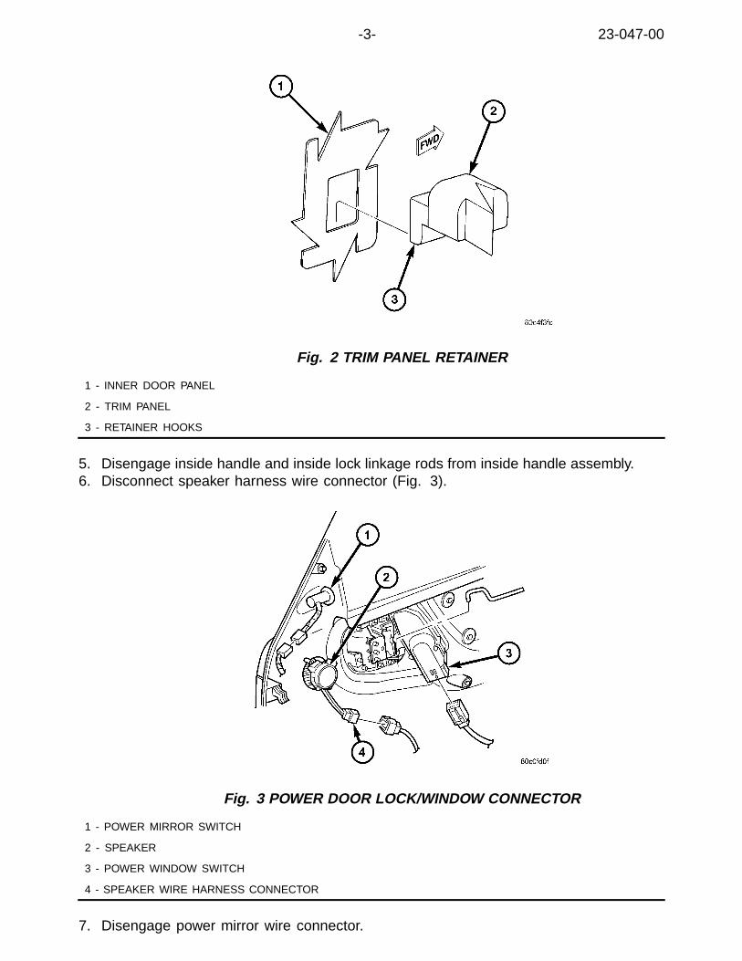
-3- 23-047-00
Fig. 2 TRIM PANEL RETAINER
1 - INNER DOOR PANEL
2 - TRIM PANEL
3 - RETAINER HOOKS
5. Disengage inside handle and inside lock linkage rods from inside handle assembly.6. Disconnect speaker harness wire connector (Fig. 3).
Fig. 3 POWER DOOR LOCK/WINDOW CONNECTOR
1 - POWER MIRROR SWITCH
2 - SPEAKER
3 - POWER WINDOW SWITCH
4 - SPEAKER WIRE HARNESS CONNECTOR
7. Disengage power mirror wire connector.

23-047-00 -4-
8. Disengage clips attaching power window/lock switch panel to door trim panel.Disengage wire connector from switch panel.
9. Separate door trim panel from vehicle.10. Partially remove waterdam.11. Position glass to access the liftplate fasteners. Remove the fasteners.12. Disengage glass from regulator lift channel.13. Position glass up into door frame (rest glass on a block of wood on door reinforcement).14. Disconnect regulator wire harness.15. Remove screws attaching window regulator to door inner panel (Fig. 4).
Fig. 4 WINDOW REGULATOR
1 - FRONT DOOR
2 - POWER WINDOW REGULATOR
3 - NUT
16. Remove window regulator from door.17. Position new window regulator p/n 05066431AB into door.18. Loosely install screws attaching window regulator to door inner panel.19. Position glass onto window regulator lift channel.20. Install glass to lift channel fasteners.21. Cycle the window glass to the full up position.22. Tighten bolts attaching lower front glass run channel to door inner panel.23. Tighten fasteners holding window regulator to door inner panel.24. Connect regulator wire harness.25. Install waterdam.26. Position trim panel at door.27. Engage wire connector for window/lock switch panel.28. Engage power mirror wire connector.29. Connect speaker harness wire connector.30. Engage inside handle and inside lock linkage rods to inside handle assembly.

-5- 23-047-00
31. Align trim panel retainer steps with inner door panel and slide trim panel into place.32. Install screws attaching trim panel to door.
POLICY:Reimbursable within the provisions of the warranty.
TIME ALLOWANCE:
Labor Operation No: 23-34-10-93 0.5 Hrs.
FAILURE CODE:
P8 New Part


2000 INDEX
GROUP 24HEATING & A/C
BULLETIN SUBJECT MODELS TSB NO.
GROUP 24 - HEATING & A/C
Improved Driver Side Floor Duct 1999 - 2000 WJ 24-01-00
A/C Heater Performance 1998 - 2000 LH/LHS/300M 24-02-00
Driver Side Heat Duct Extension Loose 2000 AN 24-03-00
Clunk Type Sound At Initial Engine Startup 2000 - 2001 PL 24-04-00
Poor Heat Distribution To Driver’s Feet 2000 AN 24-05-00
Rear A/C Blower Motor Fan Buzzing/ClickingSound
2000 - DN 24-06-00
Dual Zone Mode Control Operation 2001 - DN 24-07-00
A/C Hum or 9Fog Horn9 Sound 2001 JR 24-08-00

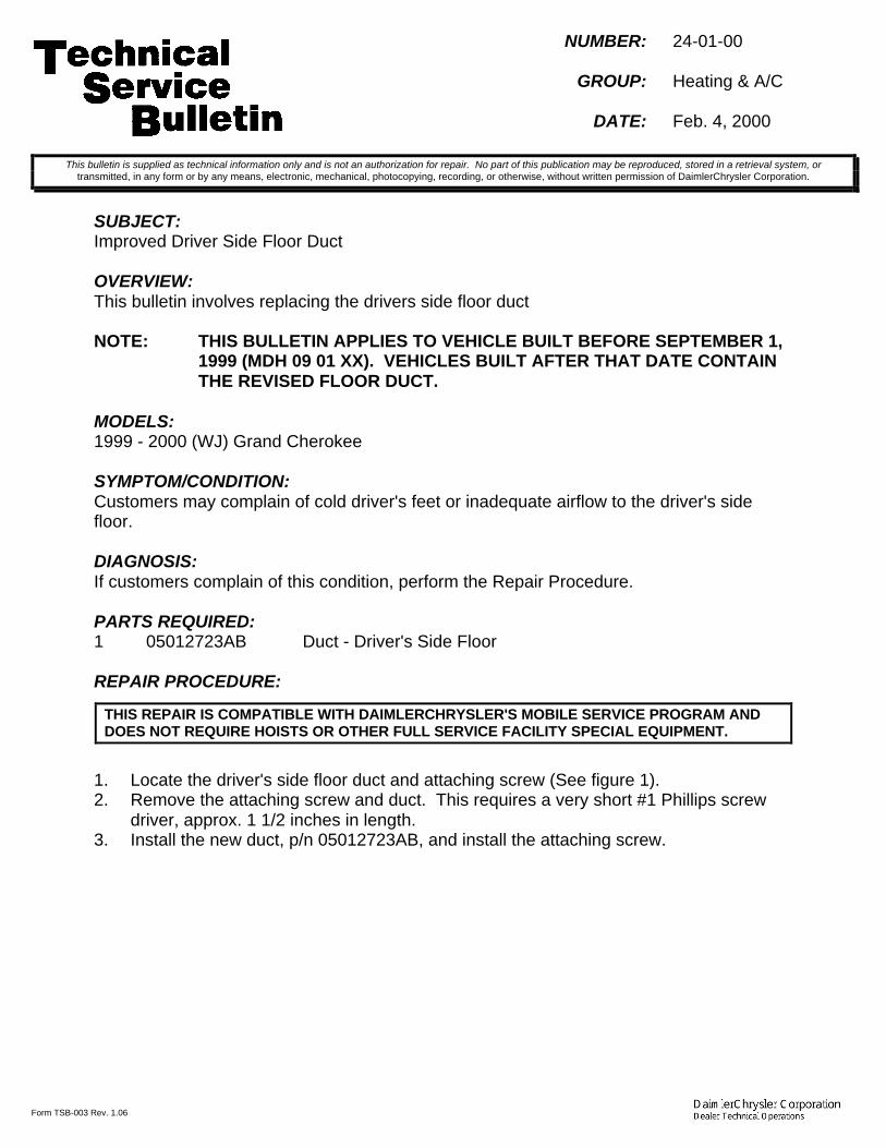
Form TSB-003 Rev. 1.06
NUMBER: 24-01-00
GROUP: Heating & A/C
DATE: Feb. 4, 2000
SUBJECT:Improved Driver Side Floor Duct
OVERVIEW:This bulletin involves replacing the drivers side floor duct
NOTE: THIS BULLETIN APPLIES TO VEHICLE BUILT BEFORE SEPTEMBER 1,1999 (MDH 09 01 XX). VEHICLES BUILT AFTER THAT DATE CONTAINTHE REVISED FLOOR DUCT.
MODELS:1999 - 2000 (WJ) Grand Cherokee
SYMPTOM/CONDITION:Customers may complain of cold driver's feet or inadequate airflow to the driver's sidefloor.
DIAGNOSIS:If customers complain of this condition, perform the Repair Procedure.
PARTS REQUIRED:1 05012723AB Duct - Driver's Side Floor
REPAIR PROCEDURE:
1. Locate the driver's side floor duct and attaching screw (See figure 1).2. Remove the attaching screw and duct. This requires a very short #1 Phillips screw
driver, approx. 1 1/2 inches in length.3. Install the new duct, p/n 05012723AB, and install the attaching screw.
This bulletin is supplied as technical information only and is not an authorization for repair. No part of this publication may be reproduced, stored in a retrieval system, ortransmitted, in any form or by any means, electronic, mechanical, photocopying, recording, or otherwise, without written permission of DaimlerChrysler Corporation.
THIS REPAIR IS COMPATIBLE WITH DAIMLERCHRYSLER'S MOBILE SERVICE PROGRAM ANDDOES NOT REQUIRE HOISTS OR OTHER FULL SERVICE FACILITY SPECIAL EQUIPMENT.

24-01-00 -2-
1. DUCT2. SCREW__________________________________
FIGURE 1
POLICY: Reimbursable within the provisions of the warranty.
TIME ALLOWANCE:Labor Operation No: 24-65-49-91 ...............................................................0.2 Hrs.
FAILURE CODE: P8 - New Part

Form TSB-003 Rev. 1.07
NUMBER: 24-02-00
GROUP: Heating & A/C
DATE: Mar. 24, 2000
SUBJECT:A/C Heater Performance
OVERVIEW:This bulletin provides diagnostic information for A/C and heater performance complaints.
MODELS:1998 - 2000 (LH) Concorde/Intrepid/LHS/300M
NOTE: PERFORM CUSTOMER SATISFACTION RECALL NO. 857, REPROGRAMPCM, FOR 2000 MODEL YEAR VEHICLES BUILT PRIOR TO AUGUST 30,1999 (MDH 0830XX).
SYMPTOM/CONDITION:Erratic operation of the A/C and heater systems including: lack of cold air, lack of hot air,unrequested mode change (ATC only), no control of mode or temperature control ordithering/tapping blend door noise. These symptoms may be accompanied by thefollowing Diagnostic Fault Codes (DTCs): Blend Door Feedback, Blend Door Stall, A/CControl Mode Door Input Shorted To Battery, In-Car Temp Sensor Failure, ATC MessagesNot Received, or Mode Door Stall.
DIAGNOSIS:Verify customer reported symptom(s) if possible. Check for the presence of DTCs with theDRB III and record on the repair order. If other than the symptoms and/or DTCs listedabove are present, repair as necessary. If the symptoms and/or DTCs listed above arepresent, perform the Repair Procedure.
REPAIR PROCEDURE:1. With vehicle at room temperature (50° to 80° F.), pull the M-1 fuse for two minutes to
erase DTCs. Replace fuse and start vehicle to recalibrate HVAC system. Operatevehicle and A/C heater system to verify that symptoms and/or DTCs are gone. Ifdithering/tapping noise or Blend Stall/Feedback DTCs re-occur, additional diagnosiswill be required.
POLICY: Reimbursable within the provisions of the warranty.
TIME ALLOWANCE:Labor Operation No: 24-50-09-90 ................................................................0.3 Hrs.
FAILURE CODE: XX - Service Adjustment
This bulletin is supplied as technical information only and is not an authorization for repair. No part of this publication may be reproduced, stored in a retrieval system, ortransmitted, in any form or by any means, electronic, mechanical, photocopying, recording, or otherwise, without written permission of DaimlerChrysler Corporation.


Form TSB-003 Rev. 1.07
NUMBER: 24-03-00
GROUP: Heating & A/C
DATE: May 5, 2000
SUBJECT:Driver Side Heat Duct Extension Loose
OVERVIEW:This bulletin involves securing the heat duct extension with a pushpin.
MODELS:2000 (AN) Dakota
NOTE: THIS BULLETIN APPLIES TO VEHICLES BUILT BETWEEN SEPTEMBER 27,1999 (MDH 0927XX) AND JANUARY 18, 2000 (0118XX).
SYMPTOM/CONDITION:The driver side heat duct extension is loose and may eventually fall off.
DIAGNOSIS:The heat duct is retained by three tabs, one located on the top of the duct and two on thebottom. Using your hand, pull on the heat duct extension. If the heat duct extension easilypulls off or the customer indicates that the heat duct extension has fallen off, perform theRepair Procedure.
PARTS REQUIRED:1 05019472AA Pushpin
EQUIPMENT REQUIRED:Drill Motor5mm or 3/16 in. Drill Bit
REPAIR PROCEDURE:
1. If the driver side heat duct extension is off, re-attach the extension onto the heatingduct.
2. Drill a 5mm (3/16 in.) hole through both the extension and the heating duct as shownin Figure 1.
3. Insert pushpin p/n 05019472AA into the drilled hole (Figure 2).
This bulletin is supplied as technical information only and is not an authorization for repair. No part of this publication may be reproduced, stored in a retrieval system, ortransmitted, in any form or by any means, electronic, mechanical, photocopying, recording, or otherwise, without written permission of DaimlerChrysler Corporation.
THIS REPAIR IS COMPATIBLE WITH DAIMLERCHRYSLER'S MOBILE SERVICE PROGRAM ANDDOES NOT REQUIRE HOISTS OR OTHER FULL SERVICE FACILITY SPECIAL EQUIPMENT.
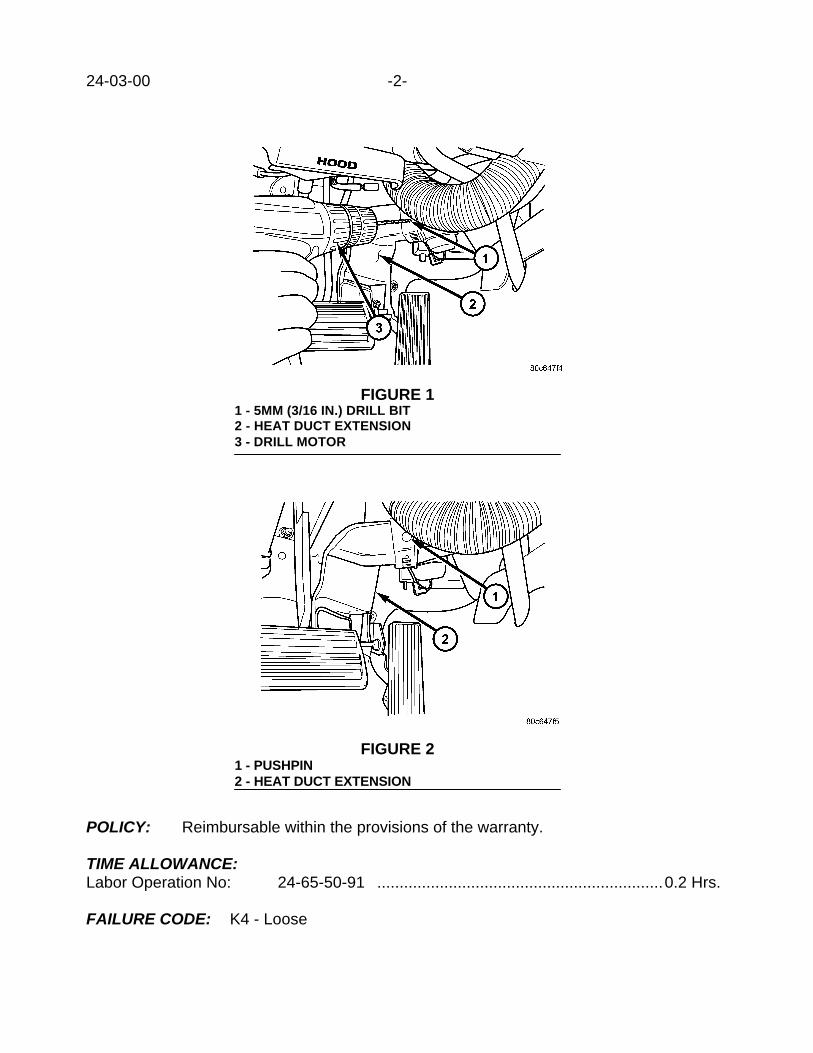
24-03-00 -2-
POLICY: Reimbursable within the provisions of the warranty.
TIME ALLOWANCE:Labor Operation No: 24-65-50-91 ................................................................0.2 Hrs.
FAILURE CODE: K4 - Loose
FIGURE 11 - 5MM (3/16 IN.) DRILL BIT2 - HEAT DUCT EXTENSION3 - DRILL MOTOR
FIGURE 21 - PUSHPIN2 - HEAT DUCT EXTENSION

Form TSB-004 Rev. 1.05
NUMBER: 24-04-00
GROUP: Air Conditioning
DATE: June 9, 2000
SUBJECT:Clunk Type Sound At Initial Engine Startup
MODELS:2000 - 2001 (PL) Neon
DISCUSSION:If the vehicle is shut off with the air conditioning compressor engaged and allowed to sitovernight, an audible clunk type sound may be heard from the engine compartment at theinitial engine startup. This sound has been traced to the A/C compressor. The sound (A/Cclunk) is generated when the compressor ingests the first liquid refrigerant after sittingovernight or for extended periods of time. This condition is most noticeable in moderate towarm ambient temperatures and is not detrimental to the operation and performance of thecompressor.
The A/C clunk issue is being addressed and a permanent solution is forthcoming. In themean time do not attempt repairs for a clunk type sound at initial engine startup. If thecustomer reports the condition, recommend that the A/C system be shut off prior toshutting off the engine and engaged at speeds over 25 MPH.
The sound has in some cases been mistaken as coming from the starter. Do not replacethe starter for this condition.
POLICY: Information Only
This bulletin is supplied as technical information only and is not an authorization for repair. No part of this publication may be reproduced, stored in a retrieval system, ortransmitted, in any form or by any means, electronic, mechanical, photocopying, recording, or otherwise, without written permission of DaimlerChrysler Corporation.


Form TSB-003 Rev. 1.08 February 3, 2000
NUMBER: 24-05-00
GROUP: Heating & A/C
DATE: June 23, 2000
SUBJECT:Poor Heat Distribution To Driver’s Feet
OVERVIEW:This bulletin involves drilling a 19 mm (3/4 in.) hole into the side of the driver side heat ductextension to improve air distribution.
MODELS:2000 (AN) Dakota
NOTE: THIS BULLETIN APPLIES TO VEHICLES BUILT BEFORE MAY 8, 2000 (MDH0508XX)
SYMPTOM/CONDITION:Driver’s right foot may feel warmer than the left foot when heat mode is selected from thetemperature control panel.
DIAGNOSIS:If the customer indicates that their right foot feels warmer than their left foot when heatmode is selected from the temperature control panel, perform the Repair Procedure.
PARTS REQUIRED:AR (2) 05019472AA Pushpin
EQUIPMENT REQUIRED:Drill Motor19 mm (3/4 in.) hole saw
REPAIR PROCEDURE:
1. Remove the driver side heat duct extension.
NOTE: SOME VEHICLES MAY HAVE THEIR DRIVER SIDE HEAT DUCTEXTENSION SECURED WITH ONE OR TWO PUSHPINS (FIGURE 1).REMOVE THE PUSHPIN(S) PRIOR TO REMOVING THE DUCT BY CUTTINGTHE HEAD OF THE PUSHPIN OFF WITH SIDE CUTTERS.
This bulletin is supplied as technical information only and is not an authorization for repair. No part of this publication may be reproduced, stored in a retrieval system, ortransmitted, in any form or by any means, electronic, mechanical, photocopying, recording, or otherwise, without written permission of DaimlerChrysler Corporation.
THIS REPAIR IS COMPATIBLE WITH DAIMLERCHRYSLER'S MOBILE SERVICE PROGRAM ANDDOES NOT REQUIRE HOISTS OR OTHER FULL SERVICE FACILITY SPECIAL EQUIPMENT.

24-05-00 -2-
2. Drill a 19 mm (3/4 in.) hole into the end of the heat duct extension as shown in Figure2.
3. Install the driver side heat duct extension.
FIGURE 11 - PUSHPIN2 - HEAT DUCT EXTENSION
FIGURE 21 - 19MM (3/4 IN.) HOLE SAW2 - DRIVER SIDE HEAT DUCT EXTENSION

-3- 24-05-00
4. Secure the driver side heat duct extension with new pushpin(s) p/n 05019472AA if theextension was secured by pushpins when it was removed.
POLICY: Reimbursable within the provisions of the warranty.
TIME ALLOWANCE:Labor Operation No: 24-65-49-92 ................................................................0.2 Hrs.
FAILURE CODE: AM - Authorized Modification


Form TSB-003 Rev. 1.08 February 3, 2000
NUMBER: 24-06-00
GROUP: Heating & A/C
DATE: Aug. 25, 2000
SUBJECT:Rear A/C Blower Motor Fan Buzzing/Clicking Sound
OVERVIEW:This bulletin involves repositioning the rear A/C assembly foam seal.
MODELS:2000 (DN) Durango
NOTE: THIS BULLETIN APPLIES TO VEHICLES EQUIPPED WITH REAR A/C(SALES CODE HBA).
SYMPTOM/CONDITION:The rear A/C blower motor fan contacts a thin plastic rib inside the rear overhead A/C unitwhen ambient temperatures exceeds 38o C. (100o F.) resulting in a buzzing/clicking sound.
DIAGNOSIS/REPAIR PROCEDURE:
1. Remove the rear A/C outlet bezel by gently separating the bezel from the headliner.2. Gently, pull the headliner down.3. Inspect the rear A/C assembly foam seal that seals the bottom of the A/C assembly to
the headliner. Carefully, unfold any section of the foam seal that may be folded overand re-secure the foam seal in its proper place. If the foam will not release from itself,the folded over portion of foam must be cut out and removed. If the foam shows nosigns of deformation, further diagnosis is required.
NOTE: IT IS IMPORTANT TO ENSURE THAT ONLY ONE LAYER OF FOAM EXISTSBETWEEN THE BOTTOM OF THE A/C ASSEMBLY AND THE HEADLINER.THE BUZZING/CLICKING SOUND CAN OCCUR WHEN MORE THAN ONELAYER OF FOAM IS PLACED BETWEEN THE BOTTOM OF THE A/CASSEMBLY AND THE HEADLINER.
4. Push the headliner back into place and re-install the rear A/C outlet bezel.
POLICY: Reimbursable within the provisions of the warranty.
TIME ALLOWANCE:Labor Operation No: 24-65-37-90 ................................................................0.2 Hrs.
FAILURE CODE: XX - Service Adjustment
This bulletin is supplied as technical information only and is not an authorization for repair. No part of this publication may be reproduced, stored in a retrieval system, ortransmitted, in any form or by any means, electronic, mechanical, photocopying, recording, or otherwise, without written permission of DaimlerChrysler Corporation.
THIS REPAIR IS COMPATIBLE WITH DAIMLERCHRYSLER'S MOBILE SERVICE PROGRAM ANDDOES NOT REQUIRE HOISTS OR OTHER FULL SERVICE FACILITY SPECIAL EQUIPMENT.


NUMBER: 24-007-00
GROUP: Heating and A/C
DATE: Nov. 10, 2000
This bulletin is supplied as technical information only and is not an authorization for repair. No part of this publication may be reproduced, stored in a retreival system,or transmitted, in any form or by any means, electronic, mechanical, photocopying, or otherwise, without written permission of DaimlerChrysler Corporation.
SUBJECT:Dual Zone Mode Control Operation
MODELS:
2001 (DN) Durango
DISCUSSION:The position of the driver side temperature control lever mandates the position of both driverand passenger blend air doors while the mode control knob is in any defrost position (Mix,between Mix and Defrost, and Defrost) (Fig. 1). When diagnosing temperature related con-cerns regarding the passenger side temperature control system, it is important to rememberthat the driver side temperature control overrides the passenger temperature control anytimethe mode control is in any defrost position.
NOTE: THE PASSENGER SIDE TEMPERATURE CONTROL IS DISABLED ANYTIME THEMODE CONTROL IS IN ANY DEFROST POSITION.
Fig. 1 MODE CONTROL
POLICY:Information Only


NUMBER: 24-008-00
GROUP: Heating & A/C
DATE: Nov. 10, 2000
This bulletin is supplied as technical information only and is not an authorization for repair. No part of this publication may be reproduced, stored in a retreival system,or transmitted, in any form or by any means, electronic, mechanical, photocopying, or otherwise, without written permission of DaimlerChrysler Corporation.
SUBJECT:A/C Hum or “Fog Horn” Sound
OVERVIEW:This bulletin involves replacing the A/C expansion valve.
MODELS:
2001 (JR) Sebring Sedan/Stratus Sedan
NOTE: THIS BULLETIN APPLIES TO VEHICLES BUILT BEFORE OCTOBER 23, 2000(MDH 1023XX).
SYMPTOM/CONDITION:Hum or "fog horn" sound coming from the A/C expansion valve within a few seconds of A/Cclutch engagement, or immediately after A/C clutch disengagement. This sound can lastanywhere from one to three seconds and can be confused with the sound a vehicle brakingsystem makes as the vehicle is allowed to creep forward while at curb idle. Vibration fromthis condition can be felt in the passenger compartment, especially in the steering wheel andseats.
DIAGNOSIS:Due to the random occurrence of this sound, it is not always possible to successfully testfor this condition. Therefore, the complaint must be carefully reviewed with the customer toavoid replacing an A/C expansion valve unnecessarily.
PARTS REQUIRED:
Qty. Part No. Description
1 04596318AA Valve, A/C Expansion
NOTE: THE MOPAR REPLACEMENT A/C EXPANSION VALVE MUST HAVE A DATE OFOCTOBER 2000 OR LATER PRINTED ON THE BOX TO BE USED FOR THIS REPAIR.
REPAIR PROCEDURE:1. Replace A/C expansion valve as described on page 24-38 of the 2001 Sebring/Stratus
Sedan Service Manual (Publication No. 81-270-1021).
NOTE: REPLENISH THE SYSTEM WITH SD15 PAG OIL MATCHING THE AMOUNT THATWAS REMOVED DURING REFRIGERANT RECOVERY, AND RECHARGE THE SYSTEMWITH R134A REFRIGERANT TO THE QUANTITY LISTED ON THE A/C SYSTEM UNDER-HOOD WARNING LABEL.

24-008-00 -2-
POLICY:Reimbursable within the provisions of the warranty.
TIME ALLOWANCE:
Labor Operation No:
24-35-20-92 Valve, Expansion (H-Valve) - Replace 0.2 Hrs.
24-01-02-01 Air Conditioning System - Test, Recoverand Recharge
0.6 Hrs.
FAILURE CODE:
P8 New Part