MASTER THESIS IN CIVIL...
114
UNIVERSITY OF PADUA DEPARTMENT OF CIVIL ENVIRONMENTAL AND ARCHITECTURAL ENGINEERING MASTER THESIS IN CIVIL ENGINEERING BEHAVIOUR OF OLD RC BEAM-COLUMN JOINTS STRENGTHENED WITH STRAIN HARDENING CEMENTITIOUS COMPOSITES AND NEAR-SURFACE MOUNTED CFRP LAMINATES UNDER CYCLIC LOADING Supervisors: Prof. José Sena Cruz, University of Minho Prof. Carlo Pellegrino, University of Padua Student: Fabio Raimondo Li Prizzi N°: 1013856 Academic year 2012-2013
Transcript of MASTER THESIS IN CIVIL...

UNIVERSITY OF PADUA DEPARTMENT OF CIVIL ENVIRONMENTAL AND
ARCHITECTURAL ENGINEERING
MASTER THESIS IN CIVIL ENGINEERING
BEHAVIOUR OF OLD RC BEAM-COLUMN JOINTS STRENGTHENED WITH STRAIN HARDENING CEMENTITIOUS COMPOSITES AND NEAR-SURFACE MOUNTED CFRP LAMINATES UNDER CYCLIC LOADING
Supervisors: Prof. José Sena Cruz, University of Minho Prof. Carlo Pellegrino, University of Padua
Student: Fabio Raimondo Li Prizzi N°: 1013856
Academic year 2012-2013

Key words
RC beam-column joints; Cyclic loading; Near Surface Mounted; SHCC; CFRP laminates;
Experimental research.
Abstract
Worldwide, it is well known the impact of earthquakes. The vulnerability of the existing reinforced
concrete (RC) buildings to the seismic action has an important role for these consequences.
Earthquakes have been also revealing the vulnerability of the beam-column RC joints of framed
structures to the seismic action. In particular, in the south of Europe until the eighties, the built RC
heritage may have significant deficiencies in the joint regions due to the lack of recommendations in
terms of the seismic action. So, the upgrading of these structural components to the seismic action is
mandatory. Two distinct ways can be used: rebuilding or retrofitting. The latter is usually followed
since it leads to less economic and ecological impacts. Several techniques to improve the performance
of deficient RC joints have been proposed.
In ambit of the present dissertation new retrofitting methods for seismic action are explorer. For
that purpose four beam-column RC joints without specific seismic design were initially damaged
under cyclic loading until the failure and then they were strengthened using NSM technique and Stain
Hardening Cementitious Composite (SHCC) materials. Moreover, two different retrofitting methods,
namely pre-cast and cast-in-place are studied and compared. In this work, these two approaches are
described, implemented and the several and interesting results are presented and discussed such as
ultimate capacity, initial stiffness, dissipated energy and mode of failure.

2

3
Acknowledgment
I would like to express my gratitude to my master thesis supervisors, Professor José Sena for giving
me the opportunity to have this research experience, for teaching me a lot in this field and for all the
time devoted. Special thanks are given to my supervisor (from University of Padua) Professor Carlo
Pellegrino for supporting me in this international experience.
A special thanks goes to Esmaeel Esmaeeli, PhD student at the University of Minho, which his
contribution has guaranteed a good job.
A very special thanks goes to Luca Fasan and Suzel Duarte, my friends and my colleagues, because
without his support I would not be able to overcome all the difficulties encountered.
Special thanks are given to José Melo, PhD student at the University of Aveiro, for his professional
contribution to this work and to Professor Joaquim Barros (fromUMinho) and Professor Humberto
Varum for their suggestions.
I would like to express many thanks to all the technicians from UMinho, in particular to Engr.
Marco Jorge and Mr. António Matos.
I must also acknowledge Hadi Baghi, PhD student at the University of Minho, for helping me in
many occasions.
Remarkable helps were given by the companies: S&P Clever Reinforcement Ibérica Lda., Hilti
Portugal-Produtos e Serviços, Lda., Sika Portugal - Produtos Construção e Indústria, S.A. that provide
fundamental materials.
I would like to express my deep to all my friends for all adventures lived.
Finally the most important I would like to thank my parents and my sister Lucia, for always
encouraging me and because thanks to their support I have been able to reach this goal. I also thank
the most important person in my life, I thank Lidia, for giving me the wonderful moments.

4

5
Index
Key words .............................................................................................................................. 1
Abstract .................................................................................................................................. 1
Acknowledgment ................................................................................................................... 3
Index ...................................................................................................................................... 5
Figures Index ......................................................................................................................... 9
Tables Index......................................................................................................................... 15
Nomenclature ....................................................................................................................... 17
Glossary ............................................................................................................................... 17
Chapter 1: Introduction ........................................................................................................ 19
Chapter 2: State of the Art ................................................................................................... 21
2.1 Fiber Reinforced Polymer (FRP) strengthening techniques: types, research and
standards. .............................................................................................................................. 21
2.1.1 FRP evolution in structural strengthening ...................................................... 21
2.1.2 FRP research about strengthening of RC elements ........................................ 25
2.1.3 Guides and standards regard NSM technique ................................................. 30
2.2 RC joints with plane rebars: typical damages, standards and different retrofitting31
2.2.1 Typical damages for beam-column joint under cyclic load............................ 31
2.2.2 Strengthening techniques for RC joints under cyclic load ............................. 33
2.3 Engineered Cementitious Composite (ECC): New material for reinforcement and repair
of existing concrete structures. ............................................................................................. 37
2.3.1 Fiber reinforced cement (FRC) ....................................................................... 37
2.3.2 Mechanical classification of FRC: strain softening, strain hardening and
micromechanical design .................................................................................................... 39
2.3.3 Engineered Cementitious Composites: main features and retrofitting applications
40

6
Chapter 3: Experimental Project .......................................................................................... 45
3.1 Project’s introduction ............................................................................................. 45
3.2 Original state of the specimens and the corresponding behavior ........................... 46
3.2.1 Geometry configurations ................................................................................ 46
3.2.2 Material Characterization ............................................................................... 49
3.2.3 Experimental test setup ................................................................................... 49
3.2.4 Failure Modes and Hysteresis Behaviors ....................................................... 51
3.3 Material characterization ........................................................................................ 57
3.3.1 Cementitious material ..................................................................................... 57
3.3.2 Carbon fiber reinforced elements ................................................................... 58
3.3.3 Epoxy adhesives ............................................................................................. 59
3.3.4 Chemical anchors ............................................................................................ 60
3.3.5 Strain gauges ................................................................................................... 61
3.4 Strengthening design .............................................................................................. 62
3.4.1 Pre-cast solution .............................................................................................. 62
3.4.2 Cast-in-place solution ..................................................................................... 67
3.4.3 General retrofitting details .............................................................................. 68
3.5 Specimens preparation ........................................................................................... 71
3.5.1 Joint JPA-1: precast solution .......................................................................... 71
3.5.2 Joint JPC: precast strengthening system ......................................................... 75
3.5.3 Joint JPB: cast-in-place strengthening system ................................................ 79
3.5.4 Joint JPA-3: cast-in-place strengthening system ............................................ 82
Chapter 4: Results ................................................................................................................ 85
4.1 Force versus Displacement .................................................................................... 85
4.2 Stiffness .................................................................................................................. 90
4.3 Dissipated energy ................................................................................................... 91
4.4 Specimens failure modes ....................................................................................... 92

7
Chapter 5: Conclusions ........................................................................................................ 99
Bibliography ...................................................................................................................... 101
ANNEXES ......................................................................................................................... 105

8

9
Figures Index
Figure 1.1 - Seismic landscape of southern Europe [1] ............................................................ 19
Figure 2.1 – External steel plate [7] ......................................................................................... 22
Figure 2.2 – Steel jackets [7] .................................................................................................... 22
Figure 2.3 - Externally bonded FRP concrete columns ............................................................. 23
Figure 2.4 – Externally bonded FRP on masonry ...................................................................... 23
Figure 2.5 - MF-EBR technique [8] ........................................................................................... 23
Figure 2.6 - NSM with circular bar ........................................................................................... 25
Figure 2.7 - NSM with rectangular bars ................................................................................... 25
Figure 2.8 – Failure mode of beam strengthened with steel fabric [13] .................................. 26
Figure 2.9 - brittle failure mode due to epoxy-concrete debonded [13] .................................. 26
Figure 2.10 - FRP strips failures in MF-FRP system [14] ........................................................... 27
Figure 2.11 – Curve Load-Displacement [14] ........................................................................... 27
Figure 2.12 – MF-EBR FRP system, bearing failure mode [15]................................................. 27
Figure 2.13 – EBR system, peeling failure mode [15] ............................................................... 27
Figure 2.14 – NSM system, detachment of concrete layer [16] ............................................... 28
Figure 2.15 - NSM versus EBR: typical failure modes [17] ....................................................... 29
Figure 2.16 – Detail of T joint, Italy 70s [22] ............................................................................ 31
Figure 2.17 – Detail of X joint, Italy 70s [22] ............................................................................ 31
Figure 2.18 – RC joint with plane rebars designed only for gravity loads................................ 32
Figure 2.19 – Scheme of internal stresses inside the RC joint [23]) ......................................... 32
Figure 2.20 – 3D corner RC joint, strengthening with steel cage and GFRP [25] ..................... 33
Figure 2.21 – RC joint retrofitted with MF-EBR FRP technique [27] ........................................ 35
Figure 2.22 – RC column base retrofitted with NSM technique [28] ....................................... 36
Figure 2.23 – strengthening direct method [29] ...................................................................... 36
Figure 2.24 – strengthening indirect method [29] ................................................................... 36
Figure 2.25 - FRC composite model considering two components: fiber and matrix [30] ...... 37
Figure 2.26 – Different uses of FRC [30] ................................................................................... 38
Figure 2.27 - Tensile failure modes observed in cementitious materials [31] ......................... 39

10
Figure 2.28 – (a) Strain-Softening behavior: single crack and immediate localization ........... 40
Figure 2.29 - The deformation behavior of cementitious composites [32] .............................. 41
Figure 2.30 - Different stress distribution between R/C and R/ECC before and after matrix cracking
[32] ........................................................................................................................................... 42
Figure 2.31 – Masonry beam strengthened with SHCC layer with variable thickness [34] ..... 43
Figure 2.32 – Typical cracks pattern and failure modes of the beams, CB=Concrete Beam, BF=Beam
with CFRP sheet, BS=Beam with SHCC, BH=Beam with HPC [36] ............................................ 43
Figure 3.1 – Geometry details in mm of specimens JPA-1 and JPA-3 ...................................... 47
Figure 3.2 – Geometry details in mm of specimen JPB ........................................................... 47
Figure 3.3 – Geometry details in mm of specimen JPC ............................................................ 48
Figure 3.4 – Test machine setup [38] ....................................................................................... 50
Figure 3.5 – First displacement law [38] .................................................................................. 51
Figure 3.6 – Second displacement law [38].............................................................................. 51
Figure 3.7 - JPA-1 steel reinforcement and relative crack pattern .......................................... 52
Figure 3.8 - JPA-3 steel reinforcement and relative crack pattern .......................................... 52
Figure 3.9 - JPB steel reinforcement and relative crack pattern .............................................. 54
Figure 3.10 - JPC steel reinforcement and relative crack pattern ............................................ 55
Figure 3.11 – Evolution of total energy dissipation, specimens at UA [38] ............................. 56
Figure 3.12 – CFRP strips .......................................................................................................... 58
Figure 3.13 – Carbon fibers sheet ............................................................................................ 58
Figure 3.14 – Anchors ............................................................................................................... 60
Figure 3.15 - HIT-HY 150 MAX .................................................................................................. 61
Figure 3.16 – Pre-cast panel system ........................................................................................ 63
Figure 3.17 - Casting SHCC for precast panels ......................................................................... 64
Figure 3.18 - Curing conditions of precast panels .................................................................... 64
Figure 3.19 – Cutting 10mm depth .......................................................................................... 64
Figure 3.20 – Cutting 20mm depth .......................................................................................... 64
Figure 3.22 – Filling grooves with epoxy glue .......................................................................... 65
Figure 3.23 – Cleaning of carbon FRP laminates ..................................................................... 65
Figure 3.24 – surface not completely roughened .................................................................... 65
Figure 3.25 – Roughned surface ready .................................................................................... 65

11
Figure 3.26 – Fresh selfcompact SHCC ..................................................................................... 66
Figure 3.27 – Rectangular panels casted and cover with plastic film ...................................... 66
Figure 3.28 – Cast-in-place system .......................................................................................... 67
Figure 3.29 – Strengthened area.............................................................................................. 68
Figure 3.30 – FRP laminates geometry for cross area is the same between precast and cast-in-place
system ...................................................................................................................................... 69
Figure 3.31 – intersection between carbon laminates ............................................................. 69
Figure 3.32 – Lateral NSM strengthening on JPB, column is the vertical blue element .......... 69
Figure 3.33 – fibers glued on laminate for a length of 5cm, red lines mark the borders ........ 70
Figure 3.34 – Laminates with extensions ready ....................................................................... 70
Figure 3.35 - 3D view of JPA-1 joint after the precast retrofitting ........................................... 71
Figure 3.36 – Casting corner .................................................................................................... 72
Figure 3.37 – Leveling of the surface ....................................................................................... 72
Figure 3.38 – New corner ......................................................................................................... 72
Figure 3.39 – Epoxy resin for injection ..................................................................................... 72
Figure 3.40 – Surface roughned ............................................................................................... 72
Figure 3.41 – Hilti’s hammer .................................................................................................... 72
Figure 3.42 – Drilling panel ...................................................................................................... 73
Figure 3.43 – Putting the anchors ............................................................................................ 73
Figure 3.44 – Spreading of the glue ......................................................................................... 73
Figure 3.45 – Joint strengthened.............................................................................................. 73
Figure 3.46 – Joint rotation ...................................................................................................... 74
Figure 3.47 - 3D view of JPC joint after the precast retrofitting .............................................. 75
Figure 3.48 – Concrete removal ............................................................................................... 76
Figure 3.49 – Application of the formwork .............................................................................. 76
Figure 3.50 – Application of the strain gauges ........................................................................ 76
Figure 3.51 – Casting of the new concrete ............................................................................... 76
Figure 3.52 – Top surface roughened ...................................................................................... 76
Figure 3.53 - Lateral surface roughened .................................................................................. 76
Figure 3.54 – Putting the anchors on top surface .................................................................... 77
Figure 3.55 – Drilling of hole in the panel ................................................................................ 77

12
Figure 3.56 – Putting of the strain gauges ............................................................................... 77
Figure 3.57 – Putting of the anchors in the lateral surface ..................................................... 77
Figure 3.58 – Spreading of glue in the panel ........................................................................... 78
Figure 3.59 – Installation of the panel ..................................................................................... 78
Figure 3.60 – Spreading of epoxy glue on the .......................................................................... 78
Figure 3.61 - Spreading of epoxy glue on the panel ................................................................. 78
Figure 3.62 – Strengthening completed ................................................................................... 78
Figure 3.63 – Lateral strengthening completed ....................................................................... 78
Figure 3.64 – 3D strengthened ........................................................................................... 79
Figure 3.65 – Preparation of the mix ....................................................................................... 80
Figure 3.66 – Casting SHCC material ........................................................................................ 80
Figure 3.67- Casting SHCC material ......................................................................................... 80
Figure 3.68 - Preservation ........................................................................................................ 80
Figure 3.69 – Cutting grooves on the top surface .................................................................... 80
Figure 3.70 – Cutting grooves on the lateral surface ............................................................... 80
Figure 3.71 – Preparation of CFRP laminate with carbon sheet .............................................. 81
Figure 3.72 – CFRP laminate with carbon sheet ...................................................................... 81
Figure 3.73 – Installation of CFRP bars into the groove. .......................................................... 81
Figure 3.74 – Putting of anchors in JPB .................................................................................... 81
Figure 3.75 - 3D view of JPA-3 joint after the precast retrofitting ........................................... 82
Figure 3.76 – Casting of normal concrete ................................................................................ 83
Figure 3.77 – Casting of SHCC .................................................................................................. 83
Figure 3.78 - Preservation ........................................................................................................ 83
Figure 3.79 – Cubic specimens ................................................................................................. 83
Figure 3.80 – Cutting grooves on JPA-3 ................................................................................... 83
Figure 3.81 – Grinders .............................................................................................................. 83
Figure 3.82 – View 1 of CFRP bars into the groove .................................................................. 84
Figure 3.83 - View 2 of CFRP bars into the groove ................................................................... 84
Figure 3.84 – Drilling the hole on the top surface .................................................................... 84
Figure 3.85 – Putting the anchors on JPA-3 ............................................................................. 84
Figure 4.1 – Force (Fc) versus displacement (δ) response for the specimens JPA-1R and JPA-386

13
Figure 4.2 - Force (Fc) versus displacement (δ) response for the specimens JPA-3R and JPA-386
Figure 4.3 – Force (Fc) versus displacement (δ) response for the specimens JPB-R and JPB ... 87
Figure 4.4 – Force (Fc) versus displacement (δ) response for the specimens JPC-R and JPC.... 87
Figure 4.5 – JPA-1R’s crack pattern .......................................................................................... 92
Figure 4.6 – Cracks on the beam .............................................................................................. 92
Figure 4.7 – Diagonal cracks in the joint region....................................................................... 92
Figure 4.8 - Detachment of the old concrete cover .................................................................. 93
Figure 4.9 – Micro-crack on the SHCC panel along longitudinal carbon laminate .................. 93
Figure 4.10 – JPC-R’s crack pattern .......................................................................................... 93
Figure 4.11 – JPC-R after test ................................................................................................... 94
Figure 4.12 – Bending failure in the beam ............................................................................... 94
Figure 4.13 – Bending failure in the beam and several micro-cracks in the joint area ........... 94
Figure 4.14 – Micro-cracks in SHCC panel along longitudinal carbon laminate location ........ 94
Figure 4.15 – JPA-3R’s crack pattern ........................................................................................ 95
Figure 4.16 – Crack on the top surface, JPA-3 .......................................................................... 95
Figure 4.17 – Failure of the joint region in JPA-3 ..................................................................... 95
Figure 4.18 – Crack on the lateral surface, JPA-3 .................................................................... 96
Figure 4.19 – Failure of the longitudinal bars, JPA-3 ............................................................... 96
Figure 4.20 – JPB-R’s crack pattern .......................................................................................... 96
Figure 4.21 – Crack on the top surface, JPB joint ..................................................................... 97
Figure 4.22 – Crack on the bottom surface, JPB joint .............................................................. 97

14

15
Tables Index
TABLE 1 – STEEL REINFORCEMENT DETAILS ......................................................................................... 48
TABLE 2 – MECHANICAL PROPERTIES OF THE LONGITUDINAL STEEL BARS [38] ..................... 49
TABLE 3 – JPA-3 UNRETROFITTED PERFORMANCES .............................................................. 53
TABLE 4 – JPB UNRETROFITTED PERFORMANCES ................................................................. 54
TABLE 5 - JPC UNRETROFITTED PERFORMANCES .................................................................. 55
TABLE 6 – RESUMING RESULTS ............................................................................................... 56
TABLE 7- CFRP LAMINATES PROPERTIES ........................................................................................ 58
TABLE 8 - CFRP SHEET PROPERTIES ................................................................................................... 58
TABLE 9 - CHARACTERISTIC OF S&P RESIN 220 .................................................................... 59
TABLE 10 - CHARACTERISTIC OF S&P RESIN EPOXY 50 ......................................................................... 59
TABLE 11 - CHARACTERISTIC OF SIKADUR®-52 INJECTION ..................................................................... 60
TABLE 12 – MECHANICAL PROPERTIES OF ANCHORS .............................................................................. 60
TABLE 13 - MATERIAL PROPERTIES FOR CURED ADHESIVE ...................................................................... 61
Table 14 – Main results obtained in the tested specimens ...................................................... 89
Table 15 – Strength degradation at the peak load for all the tests ......................................... 90
Table 16 – Initial Stiffness ........................................................................................................ 91
Table 17 – Dissipated energy ................................................................................................... 91

16

17
Nomenclature
JPA Joint reinforced with Plane bars, reinforcement details A
JPA-1 Joint reinforced with Plane bars, reinforcement details A, specimen 1
JPA -3 Joint reinforced with Plane bars, reinforcement details A, specimen 2
JPB Joint reinforced with Plane bars, reinforcement details B, specimen 3
JPC Joint reinforced with Plane bars, reinforcement details C, specimen 4
JPA-1R Retrofitted specimen JPA-1
JPA-3R Retrofitted specimen JPA-3
JPB-R Retrofitted specimen JPB
JPC-R Retrofitted specimen JPC
dc Displacement at the top of the column
Fc Force applied on the top of the column
Ei Initial Stiffness
Ed Dissipated Energy
Glossary
EBR Externally Bonded Reinforcement
FRP Fibre Reinforced Polymers
MDL-CFRP Multidirectional Laminate of Carbon Fibre Reinforced Polymer
MF-EBR Mechanically Fastened and Externally Bonded Reinforcement
MF-FRP Mechanically Fastened Fiber Reinforced Polymer
NSM Near-Surface Mounted
RC Reinforced Concrete
SHCC Strain Hardening Cementitious Composites
ECC Engineered Cementitious Composite

18

19
Chapter 1
Introduction
In recent years seismic events have demonstrated the high seismic vulnerability of existing
reinforced concrete buildings. As can be seen in the Figure 1.1 this problem assumes a relevant
importance in Europe, considering the great amount of seismic areas as Portugal, Spain, Italy,
Balkans, Greece and Turkey.
Figure 1.1 - Seismic landscape of southern Europe [1]
During the 19th century the economic developing and the increasing of world’s population led to
growth of cities and the development of buildings using reinforced concrete as one of the main
materials for the constructions. According to data published by ISTAT [2], just in Italy until 2000 the
percentage of residential buildings made with reinforced concrete is 68.5% and the percentage of
industry building made with this material is 25.1%. The majority of these buildings were built in a
period prior to the adoption of current guidelines regarding to the construction in seismic areas.
Therefore existing structures were designed only for gravity load presenting. Thus the corresponding
seismic behavior is characterized by brittle failure mechanisms such as shear failure on the beams
and columns or failure of concrete element due to reaching the limit of ultimate tensile and
compression strength. These weak behaviors are due to typical structural deficiencies such as poor

20
transverse reinforcement, inadequate confining in the potential plastic regions, insufficient amount of
column longitudinal reinforcement, lower quality of the materials like smooth steel bars for
longitudinal and transverse reinforcements and low-strength concrete or structures designed with
reference to seismic requirements of old design [3]. Hence the need of developing new strengthening
techniques and/or retrofitting in order to increase the seismic performance of existing structures is
mandatory. In the last two decades, the use of fiber reinforced polymer materials has significantly
increased for strengthening existing concrete structures. However the use of these materials in seismic
retrofitting has been roughly explored. For these reasons the objective of this thesis is to study new
strengthening systems for the seismic retrofitting RC joints. In particular four beam-column joints
previously tested under cyclic loading were subsequently strengthened using new strengthening
systems supported on the NSM technique and using Strain Hardening Cementitious Composite
(SHCC) materials. Two different realization processes, pre-cast and cast-in-place processes, are
proposed, studied and compared.
Objectives:
• Realize a strengthening solution for existing beam column joints by adopting two
procedures, pre-cast and cast-in-place;
• Validate the performance of the strengthening under cyclic load;
• Compare the results with the aim to highlight the potential of pre-cast on cast-in-place
solution.
The present thesis is divided in five main chapters. The outline of the thesis is briefly described in
the following paragraphs.
Chapter 1 gives an overview of the present work.
Chapter 2 discusses the studies of the existing strengthening techniques, highlighting the
advantages and disadvantages in their applications. Moreover a section is devoted to composite
materials description.
Chapter 3 explains the experimental program carried out in this work. It discusses the main steps
to be achieved in terms of implementing the strengthening techniques proposed.
Chapter 4 presents the obtained results. The several parameters were analyzed, mainly curve force
versus displacement; maximum forces in both directions; increment in terms of maximum forces;
initial stiffness; dissipate energy; strength degradation; failure mode analysis.
Finally, Chapter 5 is devoted to the main conclusions obtained.

21
Chapter 2
State of the Art
This chapter is divided in three paragraphs. The first one explains the evolution and the application
of FRP strengthening of concrete elements. The problem of beam column joint under cyclic loading
was discussed in paragraph two while the last paragraph refers to fiber reinforced cementitious.
2.1 Fiber Reinforced Polymer (FRP) strengthening te chniques: types,
research and standards.
2.1.1 FRP evolution in structural strengthening
The problem of strengthening or retrofitting existing concrete structures to resist higher loads, to
recover the loss of the strength due to deterioration, to overcome design or construction deficiencies,
to increase ductility or to satisfy the new standards on constructions has been resolved using
traditional materials with traditional construction techniques. Externally bonded steel plates (Figure
2.1), steel or concrete jackets (Figure 2.2) and external post-tensioning are just some of the many
traditional techniques available [4] [5] [6] . However, the last twenty years, extensive research has
been conducted on the strengthening or retrofitting using composite materials made of fibers
embedded inside a polymeric resin, also known as fiber-reinforced polymers (FRP) [4].
The growing interest of using FRP materials are due to several advantages compared to traditional
ones such as their lightweight, noncorrosive character and high tensile strength; moreover these
materials are readily available in several forms: unidirectional strips made by pultrusion process,
sheets or fabrics made by fibers in one or two directions and in the form of bars. This last aspect
becomes important where the aesthetics or the access is a concern; in fact FRP systems can also be
used in areas with limited access where traditional techniques would be difficult to be implemented.
The cost of fibers and resins composing the FRP systems are relatively expensive compared with
traditional strengthening materials such as concrete and steel but labor and equipment costs to install
FRP systems are often lower;

22
In addition of that when the life cycle analysis is accounted, FRP systems are more competitive.
Externally bonded FRP systems for the retrofit of concrete structures (Figure 2.3) was developed in
the 1980s in both Europe and Japan [4] as alternates to steel plate bonding.
The externally bonded technique was firstly used in many bridges and buildings with steel plates
in the tension zones of concrete members. The plates were fixed to concrete with adhesive resins.
This technique is viable for increasing the flexural strength but the problem of deterioration of the
bond between the steel and concrete due to corrosion led to the substitution of the steel by FRP
materials. Externally bonded FRP is a well-established technique used for the strengthening of
concrete structures and consists of bonding polymeric fabrics or prefabricated laminates to the
exterior surface of the element to be strengthened by the use of an adhesive. This technique is also
called Externally Bonded Reinforcement EBR-FRP. Different types of matrix (inorganic cement or
organic epoxy resin), fibers (basalt, steel fiber in lieu of glass and carbon) and adhesives are available
in the market for the present purpose. Experimental work using FRP materials for retrofitting concrete
structures was reported as early as 1978 in Germany [4]. Currently there are a lot of projects using
FRP systems. EBR-FRP system, as well known, is often used in structural concrete elements but
some application in other field is possible to find although for these structures exist cheaper solutions
(Figure 2.4). While reduction of the workspace, feasibility of the applying the pre-stressing force to
the FRP bars as well as the achievement of a high ratio of strength to the added weight are the most
highlighted advantages of this technique, the low resistance of the binder (typically epoxy) compared
with the high tensile strength of the fibers is known as the major disadvantage.
Moreover the installation of an EBR-FRP system often requires time-consuming and specialized
surface preparation of the concrete to provide a rough surface needed to develop adequate bond
Figure 2.1 – External steel plate [7]
Figure 2.2 – Steel jackets [7]

23
strength between the FRP and the concrete substrate. The concrete typically needs to be sandblasted,
cleaned and taking irregularities off prior to the application of the strips. An alternative of EBR-FRP
is a method nominated Mechanically Fastened FRP (MF-FRP) where the epoxy bond is substituted
by mechanical anchoring metal. The MF-FRP method is rapid, uses conventional typical available
hand-tools, lightweight materials and unqualified labor (
Figure 2.5). Another alternative and interesting technique consists in the combining of the two
methods above described, where the bond between multi-directional laminates and concrete cover is
provided by mechanical anchoring and binder. This strategy is called Mechanically Fastened and
Externally Bonded Reinforcement (MF-EBR).
Figure 2.5 - MF-EBR technique [8]
One of the biggest weaknesses of the FRP is the vulnerability of these materials to mechanical
impacts and high temperatures as it highlights several times inside standards from ACI, CNR and
Euro Codes [4] [6] [9].
Figure 2.3 - Externally bonded FRP concrete columns
Figure 2.4 – Externally bonded FRP on masonry

24
These problems have led to the development of alternative strengthening system such as the Near
Surfaced Mounted (NSM) technique. While it does not completely solve the problem of heat surely
the problem of mechanical impacts is resolved.
NSM system consists on cutting grooves into the concrete cover of the RC element to be
strengthened and introduce prefabricates FRP systems inside the grooves and filled them with epoxy
or grout adhesive (Figure 2.6 & Figure 2.7). Depending on the type of the structure to be strengthened,
the selection of fiber materials may differ, carbon fibers are mostly used in concrete structures
whereas glass bars are applied to RC structures also and the masonry or timber ones. FRP bars can
be manufactured in a different variety of shapes and with a different variety of external surface
texture. Hence the section may be round, square, rectangular and oval bars, as well as strips while the
external surface can be smooth, sand blasted, sand coated, or roughened. The choice depends on the
different advantages obtained but is strongly constrained to the specific situation: such as the depth
of the cover, the availability as well as the cost. For example, square bars maximize the bar sectional
area to groove section area ratio while using strips bars the surface area to sectional area ratio are
maximized but round bars are more readily available and can be more easily anchored in pre-stressing
operation [10].
The most common and the best performing groove filler is epoxy paste. The epoxy can have low
or high viscosity. Low-viscosity epoxy can be poured easily while high viscosity are used to avoid
dripping. Although the mechanical characteristics are lower than epoxy, cement paste or mortar has
been explored in place of epoxy with the purpose to lower the material cost, reduce the hazard to
workers, minimize the environmental impact, allow effective bonding to wet substrates, and achieve
better resistance to high temperature [11]. As Bisby [11] The epoxy resins have good mechanical
proprieties but as soon as the temperature reaches the Tg (glass transition temperature) which ranges
in 60-82 Celsius degrees the mechanical proprieties start to dramatically decrease thus bringing to
sudden failure [4].
Bisby et al. have found [11] that: the epoxy adhesive NSM FRP strengthening system may be
capable of withstanding up to 44 minutes of fire while the performance at high temperature of NSM
FRP strengthening using a cementitious grout adhesive was more than 4 hours of fire. The bond
between FRP bar and concrete is a key point for performance of this technique. Studies [10] carried
out have showed that bond depends strongly on several parameters as mechanical properties of the
materials, surface properties of FRP reinforcement and the groove, geometry of the strengthening
system (bars or strips), dimensions of the groove and depth of the FRP reinforcement into the slit.

25
The results obtained by Sharaky et al. [12] indicated that the main failure mode for several
specimens was pull-out of the FRP bar. This mode of failure depends mainly on the bond between
bar and epoxy.
Figure 2.6 - NSM with circular bar
Figure 2.7 - NSM with rectangular bars
Comparing with the techniques listed above (EBR, MF-FRP and MF-EBR), the NSM system
presents several advantages. The main are: reduction of installation work, to prepare the surface it is
only necessary to cut the grooves, irregularities of the concrete surface does not create obstacles in
the execution, the NSM bars is less subject to debonding moreover the bars can be more easily
anchored into adjacent members. This last technique is used in the flexural strengthening of beam-
column joint, where the maximum moment typically occurs at the ends of the member.
2.1.2 FRP research about strengthening of RC elements
The considerable interest on the strengthening of RC elements using the techniques previously
mentioned is due to the good results obtained by various researchers. Comparative studies on flexural
strengthening of concrete beams with EBR technique were conducted by Balsamo et al. [13]. In
particular they compared EBR technique using different materials: CFRP laminates with traditional
epoxy-adhesive, steel fabric glued with epoxy-adhesive and cement-based. The beams were tested as
simply supported members over a clear span of 2.1 m according to a four-points bending scheme,
Figure 2.8. The cross section was rectangular with a height of 0.14 m and 0.12 m of width. The results
showed that the better values were obtained using the carbon sheet with epoxy as the percentage ratio
increment of the maximum load compared to the unstrengthen beam was 140%.

26
Figure 2.8 – Failure mode of beam strengthened with steel fabric [13]
Figure 2.9 - brittle failure mode due to epoxy-concrete debonded [13]
Interesting results were also obtained using steel strip glued with epoxy and cement where the
corresponding load increase was approximately 100%. It is also important notice the different failure
modes observed. Figure 2.9 shows the failure using CFRP laminate with epoxy; it was characterized
by critical diagonal cracking and concrete crushing, FRP debonding propagates along its longitudinal
axis with the complete detachment of the concrete cover. This failure mode is due to low resistance
of subtract compared with the high tensile strength of the fibers leading to a brittle failure of the
retrofitting. On the other side, the debonding did not occur when the steel was used as the external
reinforcing system.
As it was already mentioned the MF-FRP technique may overcome some of these challenges.
Lawrence et al. [14] studied the increase of resistance of several RC beams strengthening with MF-
FRP strips. Results demonstrated that with MF-FRP technique retrofitted beams can reach an increase
about 20% in the yield and 30% in the ultimate capacity, percentage increases reinforcement
comparable to those of EBR-FRP systems. Moreover the MF-FRP technique, according to the
authors, can result in such way as a ductile response for the strengthened beams with concrete
compression failure since (Figure 2.10 and Figure 2.11) the attachment of the FRP strip was not failed
even through very large displacements. The great problem of this failure way is the brittle crash of
concrete and this is a behavior to avoid.
By the combination of the EBR and MF-FRP another interesting technique was developed, where
the bond between multi-directional laminates and concrete cover is provided by mechanical
anchoring and adhesives. This strategy, named MF-EBR (Mechanically Fastened and Externally
bonded Reinforcement), has been developed to minimize issues of the brittle fracture of EBR and
bearing failure of fastener in MF-FRP. Studies conducted by Sena-Cruz et al. [15] evidenced that
comparing both techniques for the flexural strengthening, EBR and MF-EBR, an increase of about
37% in the load carrying capacity can be obtained by the second one.

27
Figure 2.10 - FRP strips failures in MF-FRP system [14]
Figure 2.11 – Curve Load-Displacement [14]
This better result was affected by the presence of the pre-stressed anchors. A good result was
obtained not only in the maximum load reached but also in terms of deflection In fact the deflection
at failure was increased of 87% in the beam reinforced with MF-EBR and 37% in the beam reinforced
with EBR technique. Also the ductility was better in the MF-EBR system. While peeling was the
dominant failure mode in the EBR system (Figure 2.13), the MF-EBR FRP laminates failed by
bearing (Figure 2.12).
Figure 2.12 – MF-EBR FRP system, bearing failure mode [15]
Figure 2.13 – EBR system, peeling failure mode [15]
The earlier experiments in terms of NSM technique were focused on the bending strengthening of
beams. E.g. Barros and Fortes [16] performed bending tests to assess the effectiveness of flexural
strengthening of concrete beams with NSM-CFRP. Four series of concrete beams with different
amount of longitudinal steel bars were tested. The cross sectional area of CFRP laminates applied in
the beam of each series was evaluated for doubling the ultimate load of the corresponding reference

28
beam. The results showed that the NSM strengthening was very effective not only in terms of the
beams load carrying capacity, but also in terms of deformation capacity at beam failure.
In particular, the increase on the load at the onset of yielding of the conventional reinforcement
was from 32% to 47%. The service load (the load for a deflection of L/400) was increased 45% while
the ultimate load respecting to the corresponding reference beam was doubled. The deflection of the
strengthened beam was reduced registering due to an increase in terms of stiffness of 28% (average
value) for the service load and 32%. It is important to highlight that the beams have failed in a
“ductile” flexural mode characterized by the yielding of the longitudinal reinforcement followed by
the detachment of a layer of concrete at the bottom of the beam (Figure 2.14).
Figure 2.14 – NSM system, detachment of concrete layer [16]
Barros et al. [17] have also carried out tests on flexural and shear strengthening of concrete beams
to compare the NSM with EBR technique using carbon fiber reinforced polymer (CFRP). In the test
on flexural strengthening the cross sectional area of the CFRP in the NSM and EBR systems was
evaluated in order to impose the same longitudinal equivalent reinforcement ratio. The result that the
authors obtained showed that in terms of beam load carrying capacity the NSM technique was the
most effective, but the difference between the efficacy of NSM and EBR technique decrease with
increase of the longitudinal equivalent ratio, as expected. When the NSM technique was used, in the
beam with lower bending reinforcement the increase on the ultimate load of the corresponding
reference beam was doubled. The typical observed failure modes are shown in Figure 2.15.

29
(a)
(b)
(c)
Figure 2.15 - NSM versus EBR: typical failure modes [17]
The same authors investigated the use of the NSM-FRP technique for shear strengthening of concrete
beams. Some of these beams were strengthened with NSM strips of different inclinations (45 and 90
degrees), while the equivalent amount of externally bonded FRP shear reinforcement were applied to
the rest of the beams. From the result obtained, it may sad that the CFRP shear strengthening system
increased significantly the shear resistance, and the NSM technique was the most effective. The type
of failure was fragile in the beams strengthened with the EBR technique and ductile for those
strengthened by NSM one.
Rizzo and De Lorenzis [18] investigated the shear strengthening of seven RC beams with NSM
technique. The analyzed parameters were the type of FRP round and strips bars, type of groove-filler
epoxy, different inclination (45 and 90 degrees) and different spacing. The increase in the shear
capacity was between 22% and 44% over the control beam.
Tanarslan [19] tested several beams strengthened with NSM CFRP reinforcement to enhance the
shear capacity. The beams were designed without any internal shear steel reinforcement in order to
evaluate the pure contributes of the shear retrofitting composed with CFRP bars with different
diameter and different spacing. All specimens were tested under cyclic loading. Comparing with the

30
reference beam, the result showed that this technique increases the shear capacity of a minimum 57%
and a maximum 112%.
The type of failure observed was a typical shear failure, the shear failure due to concrete cover
separation and where the spacing was minimum, a flexural failure followed by shear failure.
2.1.3 Guides and standards regard NSM technique
Particular standards for NSM technique don’t exist although ACI 440.2R-08 [4] shows how to
evaluate and design NSM system under service loads and the ultimate strength of the cross section.
However regarding NSM used under cyclic loads there is any reference as indicated in section 10 of
ACI 440.2R-08 [4]:
“CHAPTER 10—FLEXURAL STRENGTHENING […] this chapter does not apply to FRP
systems used to enhance the flexural strength of members in the expected plastic hinge regions of
ductile moment frames resisting seismic loads. The design of such applications, if used, should
examine the behavior of the strengthened frame, considering that the strengthened sections have
much reduced rotation and curvature capacities. In this case, the effect of cyclic load reversal on the
FRP reinforcement should be investigated. […]”

31
2.2 RC joints with plane rebars: typical damages, s tandards and
different retrofitting
2.2.1 Typical damages for beam-column joint under cyclic load
The beam-column joints are critical components of RC buildings. They ensure the continuity of
framed structures and allow the transfer of forces between the distinct structural elements. This
function may be compromised if the joint undergoes a high degradation typically due to shear
resistance deficiency under cyclic loading. This is a typical problem of RC buildings prior to the 80s,
characterized by the lack of seismic details and the presence of smooth bars. The RC frames were
designed only for gravity loads and in seismic conditions all the lacks of these structures are evidenced
as shear failures in the joint area, columns and beams due to lack of reinforcement to ensure the
concrete confinement; formation of bending failure in the column due absence of a previously “weak-
beam strong-column” approach. [20].
As studied by Verderame et al. [21] RC elements reinforced with plane bars do not present bending
hinge as RC elements reinforced with ribbed bars. In fact, while the second usually present several
cracks in the hinge area, the first present only one or a few cracks.
Figure 2.16 and Figure 2.17 show details of RC beam-column joint representative of a building in
north Italy built before the 70s.
Figure 2.16 – Detail of T joint, Italy 70s [22]
Figure 2.17 – Detail of X joint, Italy 70s [22]
In addition to the smooth steel bars they are characterized by a concrete characteristic compressive
strength of 20 to 25 MPa; a diameter of the longitudinal bars between 12 and 16 mm in beams and
between 12 and 14 mm in columns;

32
the thickness of the concrete cover is very small at about 15 mm, while in the vicinity of the joint
following problems are detected: (i) high steps of the stirrups (150 to 200 mm), arranged at a constant
step throughout the beam or column; lack of stirrups inside the joint region; first stirrup of the beam
far from the node; anchorage length of reinforcing bar within the node equal to the depth of the node,
with sometime a small hook at the end.
Several experimental studies show that the seismic loads can produce, on the joint with the
characteristics listed previously, a typical damage characterized by diffuse diagonals cracks in the
two directions, like in the Figure 2.18, which causes degradation of the stiffness of the joint and
deterioration of the bond between the reinforcing bars, anchored in the joint, and the surrounding
concrete.
Figure 2.18 – RC joint with plane rebars designed only for gravity loads
Figure 2.19 – Scheme of internal stresses inside the RC joint [23]

33
The joint area is subjected to internal forces Ci, regarding the stress inside steel reinforcement.
Furthermore external shear forces acting on the column Vcol and on the beam Vbi increase the stress
inside the joint as showed in Figure 2.19. Thus the joint area is subjected to horizontal force and one
vertical force por each corner and all these forces are equal to two diagonal forces forming the
mechanism of strut and tie-rod is formed. In correspondence of the high forces and the absence of
confinement of the place area, the joint breaks in traction with crack inclined around 45° (Figure
2.19).
2.2.2 Strengthening techniques for RC joints under cyclic load
The rehabilitation of RC joints has received much attention during the past two decades especially
the retrofitting systems made by a steel cage around the RC joint. The main idea of this method as
studied by Alcocer and Jirsa [24] confinement the concrete using steel L profile obtaining good
results. This method is still used.
An interesting evolution of the strengthening technique showed above was studied by E. Esmaeeli
& F. Danesh [25]. This study was focused on the strengthening of shear deficient joint of 3D
reinforced beam-column connection, using GFRP layers, mechanical anchors and L shape steel bars
to fix the retrofitting in the corners of columns without any kind of drilling in the existing concrete
(Figure 2.20). This technique was adopted to ensure the development of the maximum confinement
level could be provided by GFRP wrap in the joint region without premature debonding.
Figure 2.20 – 3D corner RC joint, strengthening with steel cage and GFRP [25]
Welded 14mm dia.
bar Steel plate 300×8×x8
CFRP placed on the
steel angle 12mm
dia. bolt

34
Two specimens were studied, one of these specimens was tested as a control specimen and the
other one was retrofitted with a proposed technique, by the combination of GFRP layers and a
configuration of steel angles. Several and important results were obtained by the authors: in the
control specimen the shear failure was formed in the joint region but in the second one the hinges
were formed in the beams with an increase of several factors like the average increase (for both the
push and pull cycles) about 50% in the load-carrying capacity compared with the control one.
Moreover visual inspection of the concrete in the joint by removing the GFRP layers after the test
confirmed integrity of the concrete in this region.
The authors Costa et al [26] performed test on several reinforced concrete joints constructed in
order to represent a poorly detailed exterior T joint of a RC frame. The different strengthening
techniques studied were based on the use of carbon strips and carbon sheets. The specimens were
designed such that the effect of a series of factors on the shear capacity of joint could be investigated.
These factors are: number of strips or number of sheet layers, mechanical anchorages, type of fiber
(carbon or glass). The results were generally interesting as increment in term of pick load for carbon
and glass fiber solutions without relevant difference between these two materials. Author highlights
that increments were not proportional to the number of fiber layers used, a specimen retrofitted with
two layers had not achieve the double strength of the specimen retrofitted with one layer. Moreover
the joints strengthened with carbon strips and carbon sheet showed an increase respect to the reference
but the second one presented a better behavior in term of pick load and dissipate energy.
Some experimental tests have also performed by Coelho et al. [27] on RC beam-column joints
strengthened with multi-directional CFRP laminates under cyclic load, Figure 2.21. The specimens
were designed with a detail in term of steel reinforcement that represent a beam-column joint of RC
buildings existent in Portugal built before the 1970. For this reason the specimens was reinforced
with plain longitudinal bars and less amount of transverse reinforcement. The experimental program
included an initial step where RC joints were tested until failure under cyclic loading and then repaired
and strengthened. Results showed that the initial properties of the joint were almost recovered. In
particular a light improvement was achieved in terms of carrying capacity with values of about 35%,
but with a reduction of ductility of 7%. In terms of dissipated energy, the reinforced joint present
higher values than the unreinforced one with a peak of about 60%.

35
Figure 2.21 – RC joint retrofitted with MF-EBR FRP technique [27]
Only few studies are available regarding the use of NSM technique for retrofitting of the RC joints.
Indeed, the literature does not have enough research in this field but however, even the few available
studies, where a variety of techniques have been applied, showed real benefits. To this end, around
the beginning of 2000 a research project, involving the application of carbon fibers laminates in the
strengthening of RC columns, has been initiated at the Department of Civil Engineering of the
University of Minho. In the first phase of this project, the main topic was the development in the
Master Thesis of Debora Rodrigues [28] of one technique for strengthening of columns with flexural
collapse and in the analysis and interpretation of the experimental behavior of pre- and post-
strengthened columns. The strengthening was made with carbon fiber laminates embedded in the
concrete cover of the columns with epoxy glue Figure 2.22.
Satisfactory results were obtained regarding the significant increase in terms of bending moment
resistance in the pre-strengthened columns with an average amount of 92%, when compared with the
reference specimens. Another meaningful result was obtained regarding the post-strengthened
columns: the bending moment resistance was approximately the same of the pre-strengthened
columns only if the existing cracks in the columns were previously sealed with epoxy.

36
Figure 2.22 – RC column base retrofitted with NSM technique [28]
Regarding the use of the NSM technique for the strengthening of RC joints Coelho at el. [29] have
carried out tests on beam-column joints to compare different methods of strengthening. In this case
the several T shape RC joints reinforced with NSM, MF-EBR and MF-FRP method were tested.
Moreover for each method two different configurations, direct (Figure 2.23) and indirect (Figure
2.24), were considered. The difference between them is the areas that are retrofitted. According to
the obtained results, in terms of initial stiffness all solutions have showed a similar behavior while
for the load carrying capacity the specimens had an increase with maximum values of 37% for MF-
EBR direct, 35% for MF-FRP direct and 70% for NSM indirect method. Conversely lower values of
ductility with a reduction of 45% for NSM direct, 8.5% for NSM indirect, 23% MF-EBR direct and
-36% MF-FRP direct was obtained. The amount of the dissipated energy was almost the same in all
the cases. These outcomes indicate the interesting performance of NSM technique.
Figure 2.23 – strengthening direct method [29]
Figure 2.24 – strengthening indirect method [29]

37
2.3 Engineered Cementitious Composite (ECC): New ma terial for
reinforcement and repair of existing concrete struc tures.
2.3.1 Fiber reinforced cement (FRC)
Fiber reinforced cement or concrete (FRC) is a composite material formed with two main
components: cementitious matrix and short discrete fibers (Error! Reference source not found.).
The cementitious matrix can be cement paste, mortar, concrete while the fibers can be of different
materials like: natural organic such as cellulose, sisal, jute, bamboo; natural mineral such as rock-
wool; and man-made such as steel, titanium, glass, carbon, polymers or synthetic, etc.
Figure 2.25 - FRC composite model considering two components: fiber and matrix [30]
The concept of using fibers as reinforcement is not new. To compensate the weak tensile strength
of traditional cementitious materials, fibers such as horse hair and straw were commonly used in
ancient times, while the first modern alternative is the use of asbestos fibers in the early 1900's.
Asbestos presented health risks and for this reason it was replaced with steel fibers. In 1970’s steel
fibers reinforced concrete (SFRC) was introduced commercially into the European market. Initially
no standards or recommendations were available and this technology was used as a substitute for
secondary reinforcement or for crack control in less critical parts of the construction. Over the past 4
decades the development and use of new product allowed several improvements. For example new
additives such as super plasticizers and viscous agents or shrinkage and corrosion reducing agents,
accelerators and retarders act on the strength but also on the workability improving the production
process [30]. The use of micro-fillers such as silica fumes and flies ash that modifies the porosity of
the matrix. The greater availability of fiber with different type end properties that allowed an
improvement to the strength, ductility, and toughness of the composite [30].

38
Up to this time, FRC have been used in numerous applications for the repair and rehabilitation of
the structures, in combination with RC or steel structures or stand-alone in light structural element
[30]. In Figure 2.26 the typical applications of FRC are illustrated.
Figure 2.26 – Different uses of FRC [30]
For those applications the FRC are applied in two different methods: thin sheet products or bulk
structures. The first one are used to produce elements such as pipes, electrical poles, slab grades and
pavement or in the rehabilitation through cladding wall, jacketing around columns, tunneling or also
fire protection [30]. The second technique is used to make structural elements with high performances
like blast resistant structures and bank vaults [30]. These two types of products have different
processing method or characteristic and both present different properties. Sheet product is made with
particular processing systems as spray up, layup, extrusion and pultrusion processes. The fiber
volume fraction is in the range of 3% to 10%. The fibers are generally aligned and set along the
direction of greater advantage with the aim of optimizing the reinforcement. In this way, it is possible
to obtain the mechanical performance in both tension and bending so that the primary steel
reinforcement could be eliminated [31]. Despite this excellent performance, application of this type
of FRC is limited by the simple geometric shape requirement while the precast nature needs a special
processing with a relative increase of costs [31].
Bulk structures are made with different percentage of fibers depending on which characteristic
needs to be improved. For example, low fiber volume fraction (<1%) are generally used for plastic
shrinkage crack control while moderate fiber volume fraction (between 1% and 2%) and large amount

39
of fibers (between 5% and 20% by volume) are used to improve characteristics such as modulus of
rupture, fracture toughness, fatigue resistance and impact load resistance. Although in this case the
major obstacles are due to the production process, and then the cost, but also the weight, since often
the steel fibers are used.
2.3.2 Mechanical classification of FRC: strain softening, strain hardening
and micromechanical design
Under tensile stresses the cementitious materials show three different behaviors (Figure 2.27):
brittle, strain-softening, and strain-hardening response. As it is shown by curve A, brittle behavior is
characterized by a linear stress-strain curve followed by an abrupt drop in tensile strength after the
first cracking. This behavior is typical in the hardened cement. Curve B represents the strain-softening
behavior typical in the most FRC materials. The rupture is characterized by a single crack. The stress
after first cracking is smaller than that at first cracking and it can be related directly to the extension
of the crack [30] .
Figure 2.27 - Tensile failure modes observed in cementitious materials [31]
Strain-hardening is represented by curve C. This behavior is characterized by two linear stress-
strain curves. In the second multi cracking occurs up to the maximum post-cracking stress and the
strain increase with strain. At that point, localization occurs, and the stress decreases with increasing
elongation. Figure 2.28 shows the failure in the strain softening and strain hardening. These particular
FRC materials are also called Strain Hardening Cementitious Composite (SHCC)

40
Figure 2.28 – (a) Strain-Softening behavior: single crack and immediate localization
(b) Strain-hardening behavior: multiple cracking ending in localization at critical crack [30]
2.3.3 Engineered Cementitious Composites: main features and
retrofitting applications
Engineered Cementitious Composites (ECC) is one of the earliest types of SHCC where using the
concept of micromechanical-base-design an ultra-ductile composite with low content of fibers was
produced (Figure 2.29). This means that the mechanical interactions between ECC's fiber and matrix
are described by a micromechanical model, which takes into account material properties to design a
ductile cement base composite for desired mechanical characteristics. Comparing with conventional
FRP where the deformation is localized, the ECC present inelastic behavior with linear and uniform
deformation on a macro scale (Figure 2.29). However these characteristics depend strongly from the
materials that are used to compose ECC. Generally the ECC is obtained mixing adding to common
ingredients of FRP (cement, sand, fly ash, water and additives) short polymeric fibers such as
Polyethylene, Polyvinyl Alcohol at moderate fiber volume fractions (Vf = 1.5%-2%) [32]. ECC has
typically an ultimate tensile strength of 5-8MPa and a strain capacity ranging from 3% to 5% [32].
The spacing between multiple cracks in a typical ECC is on the order of several millimeters, while
the crack widths are limited to the order of 100 µm [32]. The manufacture of ECC requires
conventional mixing equipment, such as a drum mixer.

41
Figure 2.29 - The deformation behavior of cementitious composites [32]
The use of ECC material in structural application is justified by the several advantages. As studied
by Li and Fischer [32] the combination of ECC with structural reinforcement leads to significant
improvements of their structural performance as compared to conventional reinforced concrete
members. In the case of Reinforced-ECC (R/ECC) structures the steel bar elongation is accompanied
by ECC elongation through the formation of several micro cracks (Figure 2.30).
The contribution of the ECC in the R/ECC structures is undoubtedly in its high tensile strength
and in its particular behavior. However the limited crack width, around a few tenths of millimeter,
prevents the penetration of corrosive agents. This characteristic makes the ECC an interesting
material also for increase the durability of the structure.
Tension strain hardening ECC has been shown to have high damage tolerance under at least three
types of severe loading: cyclic loading, fatigue loading and impact loading. The damage tolerance of
a material refers to its capability to carry additional load even when loaded to beyond the elastic limit.
This behavior is valuable to the performance of a structure in terms of collapse resistance, extension
of service life, and minimization of repair after an extreme event.
Due to these extraordinary characteristics, several authors are studying this material for different
applications as new structure or retrofitting function. Kim et al. [33] studied the mechanical
performance of sprayed ECC for repair applications. They casted several ECC panels in wood
formworks located in vertical position where ECC was sprayed inside them and other panels were
casted normally in horizontal position. In addition to that they casted some reference panels with
prepackaged mortars (PM).

42
Figure 2.30 - Different stress distribution between R/C and R/ECC before and after matrix cracking [32]
The mechanical proprieties of both ECC panels were almost the same between and compared with
the mortars the increase in terms of ultimate strain capacity was 100 times. Each ECC panel was
paired with another normal concrete panel to simulate cross section of a repaired culvert with ECC
sprayed over that. Bending tests have shown remarkable qualities of the ECC/concrete composite
beams compared with PM/concrete beams even when the beams have artificially introduced
interfacial defects above the concrete crack. The improved was twice in term of flexural stress.
The use of ECC is not limited to concrete structures but as Esameeli et al. [34] studied, this material
is applicable to masonry strengthening. Authors used strain hardening cementitious composites
(SHCC), which was designated as ECC by Li and co-workers [35], in the bottom face of the masonry
beams with a variable thickness as showed in the picture below (Figure 2.31). Different types of
beams were studied; strengthening of masonry beam with SHCC layer was compared with steel fiber
reinforced self-compacting concrete (SFRSCC). This important result meant not only an increase of
maximum load compared with normal masonry beam but even a well ductility performance for the
strengthened beams that presented a previously brittle failure after the pick load.

43
Figure 2.31 – Masonry beam strengthened with SHCC layer with variable thickness [34]
Esmaeeli et al. [36] studied the potential of a hybrid composite plate (HPC) for strengthening RC
beams. HCP are composed of a CFRP sheet that is glued to the external surface of a thin plate made
by strain hardening cementitious composite (SHCC). These panels were glued over the lateral faces
of each RC beams without any steel stirrups in their loading span. As the control specimens, other
beams had been strengthened with only SHCC plates, classical EBR-CFRP technique and also a
group of beams containing conventional steel stirrups as the shear reinforcement (group CB).
Through one static force introduced to the mid-span of these beams (Figure 2.32) following results
were obtained: In terms of maximum load carrying capacity, beams strengthened with HCP showed
19% increment when compared to the beams in groups CB. This improvement can be attributed to
the contribution of the SHCC to the resistance of the compressive strut and the fiber reinforcement
mechanisms that offer resistance to the crack opening. The main aspect of this work is the idea of a
prefabricated panel made with SHCC for the strengthening of existing RC structures. The practical
problems of spraying cement with fibers and the high costs of this new material could be avoided
with prefabricated solution.
Figure 2.32 – Typical cracks pattern and failure modes of the beams, CB=Concrete Beam, BF=Beam with CFRP sheet, BS=Beam with SHCC, BH=Beam with HPC [36]

44

45
Chapter 3
Experimental Project
Chapter 3 explains the experimental program carried out in this work. It discusses the main steps
to be achieved in terms of implementing the strengthening techniques proposed.
3.1 Project’s introduction
The experimental program of this dissertation is based on the repair of four full-scale damaged
beam-column joints which has been originally designed, manufactured and tested at Department of
Civil Engineering of University of Aveiro (UA),
Later, these specimens were transported to the Department of Civil Engineering of University of
Minho (UMinho), for the repairing/strengthening process with a novel technique which was recently
developed there.
These joints were representing interior connections of those typical RC structures that were
constructed before 70s according to Portuguese code provisions. Therefore, only gravity loads were
considered as the design actions and the plain steel rebars were used as the internal reinforcing
material for these specimens.
Shortly, this project is developed in following steps:
1) The design and implementation process of the repair and the strengthening technique which
was developed at UMinho;
2) Test of the joints by UA;
3) Analysis of the results by UMinho.

46
3.2 Original state of the specimens and the corresp onding behavior
3.2.1 Geometry configurations
The specimens studied in this dissertation are four RC beam-column joints reinforced with steel
plain rebars. These specimens were designed, manufactured and tested under cyclic loads by
University of Aveiro. The geometry of the joints was designed in order to represent an interior beam-
column connection where each column element represents a half-storey column in a building, and
each beam element represents a half-span beam as showed in Figure 3.1 to Figure 3.3. Due to the
restrictions imposed by the test setup, one column of each specimen was designed slightly shorter
than the height of the half-story. The joints were made with the goal to recreate a typical 70s RC
beam-column connection using similar material characteristics, reinforcement details and geometry
dimensions.
As showed in the Figure 3.1 up to Figure 3.3, all RC joints have similar geometry but with different
configuration of steel reinforcement. The denomination is structured in the following way: first letter
is “J” represents the Joint; second letter is “P” which means plain bars and the third one could be “A”,
“B” or “C” that indicates the increase of the steel reinforcement level. According to this nomination,
specimens were designates as JPA-1, JPA-3, JPB and JPC. UA studied more three joints in this series
that they were not included in the study conducted by UMinho on this project. Namely these beams
were JPA-2, JPA-4 and JD with the last one that deformed steel rebars were used as the internal
reinforcements. In all JP specimens, beams and columns longitudinal reinforcements as well as
stirrups were plain continuous steel rebars. There was no transverse reinforcement in the joint region
and stirrups in the beam and column had a 90° hooked end configuration. The concrete cover for all
specimens was around 20 mm thick. Figure 3.1 presents the global geometry and the cross section of
the joints JPA-1 and JPA-3; these two specimens have the same letter “A” due to the same
reinforcement configuration as it showed in drawings A1 and A2 attached at the end of thesis. The
longitudinal reinforcement of the beam was composed of 2 steel bars of 12 mm of diameter (2Φ12)
at the top and 4Φ12 at the bottom. Stirrups of 8 mm in diameter with a space of 200 mm were
considered as the transverse reinforcement of the beams. In the column, the longitudinal
reinforcements were composed of 4 steel rebars of 12 mm of diameter (one on each corner) and the
transverse reinforcement was composed of 8 mm stirrups at the steps of 250 mm. Similar to the
longitudinal reinforcements, the anchorage of the transverse reinforcements was a 90 degree hooped
shape.

47
Figure 3.1 – Geometry details in mm of specimens JPA-1 and JPA-3
The specimen denominated as JPB, presented the same reinforcement of JPA with an increment
of longitudinal reinforcements of the column as it shows in Figure 3.2.
Figure 3.2 – Geometry details in mm of specimen JPB
As it is shown in Figure 3.3, the longitudinal reinforcements used in the beams and columns of the
JPC have the same details and configurations as JPB. However, higher transverse reinforcement ratios
composed by 8 mm stirrups placed at the steps of 100 mm in both columns and beams are utilized.

48
Figure 3.3 – Geometry details in mm of specimen JPC
Longitudinal and transverse reinforcement ratios computed according to Eurocode 2 [37] are
summarized in Table 1.
TABLE 1 – STEEL REINFORCEMENT DETAILS
Beam Column
Specimens
Longitudinal
reinforcement
Transverse
reinforcement
Longitudinal
reinforcement
Transverse
reinforcement
Diameter
(mm)
ρl,beam
(%)
Diameter
(mm)
ρw,beam
(%)
Diameter
(mm)
ρl,column
(%)
Diameter
(mm)
ρw,column
(%)
JPA – 1
12
0.6
8
0.17
12
0.5
8
0.13
JPA – 3 0.6 0.17 0.5 0.13
JPB 0.6 0.17 1.0 0.13
JPC 0.6 0.34 1.0 0.34
where:
ρl,beam = the total longitudinal reinforcement ratio in the beam;
ρl,column = the total longitudinal reinforcement ratio in the column;
ρw,beam = the ratio of transverse reinforcement in the beam;
ρw,column = the ratio of transverse reinforcement in the beam.
Additional information about these joint can be found elsewhere, C. Fernandes et al. [38].

49
3.2.2 Material Characterization
3.2.2.1 Concrete
All specimens were cast on the same day and with the same concrete mixture. The concrete was
characterized by means of compression tests performed on cubic specimens of 150x150x150 mm3
which were casted together with the specimens. As results of these tests, a mean compressive strength
of 23.8 MPa was obtained. Since the estimated characteristic compressive strength was equal to 19.8
MPa, according to the Eurocode 2 [37] this concrete is categorized as C16/20.
3.2.2.2 Steel rebars
The plain rebars properties were determined by means of tensile tests. Table 2 indicates the average
mechanical properties of the steel bars used as the longitudinal reinforcements. The strength of the
plain reinforcing bars was higher than the typical values for this type of steel reinforcement in existing
buildings. However, considering that the cyclic behavior of the elements is strongly influenced by the
bond properties at the concrete-steel interface zone, the steel strength is not expected to influence the
response of the specimens, significantly.
TABLE 2 – MECHANICAL PROPERTIES OF THE LONGITUDINAL STEEL BARS [38]
Characteristic Plain bars
Tensile yield strength [MPa] 590
Ultimate tensile strength [MPa] 640
Modulus of Elasticity [GPa] 198
3.2.3 Experimental test setup
The test setup used at UA to characterize the behavior of the specimens in their original state is
illustrated in Figure 3.4. The test setup was designed to achieve an idealized supporting and loading
condition as much as possible. In this Figure 3.4, C1 and C2 represent the hydraulic actuators used to
apply the lateral load and the axial force at the top of the column, respectively. C3 and C4 represent
the load-cells that were placed between the other end of the column and its supports to register the
both lateral and axial reactions during the test, respectively. N is the axial force induced in the column
through C2 whereas dc and Fc are the lateral displacement and force on top of the column,
respectively.

50
Figure 3.4 – Test machine setup [38]
The top right of Figure 3.4 shows the schematics adopted for the arrangement of the linear variable
displacement transducers (LVDTs) to measure the local relative displacements at the interfaces of
beam-joint and column-joint (slice 1) and also the vicinities of the joint (slice 2). The test was
conducted under controlled lateral displacement condition. Two different displacement laws were
used. The first one (Figure 3.5) consists on imposing complete cycles with signal inversion
throughout eighteen displacement levels with growing amplitude. The chosen levels of the lateral
displacement imposed to the top of the column were ±1 mm, ±2 mm, ±4 mm, ±6 mm, ±10 mm, ±15
mm, 20 mm, 25mm, ±30 mm, ±40 mm, ±50 mm, ±60 mm, ±70 mm, 80 mm, ±90 mm, ±100 mm,
±110 mm and 120mm. From lateral displacement level of 6 mm to the end of the test three complete
cycles per level were performed. The second load pattern (Figure 3.6) composed of imposing
complete cycles with signal inversion throughout seven displacement levels with growing amplitude.
These levels were ±4 mm, ±10 mm, ±15 mm, ±30 mm, ±60 mm, ±90 mm, and ±120 mm. While only
the cycle with amplitude of 4 mm was repeated twice, all the other amplitudes had just one complete
cycle. Before introducing the cyclic load, the specimens were subjected to an axial load and it was
kept constant during the entire of the test. This amount of this axial load was 200 kN for JPA-1and
450 kN for the specimens JPA-3, JPB, JPC.

51
Figure 3.5 – First displacement law [38]
Figure 3.6 – Second displacement law [38]
3.2.4 Failure Modes and Hysteresis Behaviors
3.2.4.1 JPA-1 and JPA-3
The specimen JPA-1 was tested under cyclic loads that followed the second displacement law (as
showed in Figure 3.6). The imposed axial load to this specimen was 200 kN while for all other
specimens an axial load of 450 kN was applied.
The crack pattern, as indicated in Figure 3.7, clearly underlines bending failures at the end of
columns and beams close to the joint region. As explained by Verderame et al. [21], this mode of
failure is typical for RC structures where smooth bars are used as the internal reinforcement.
According Verderame et al. [21] the failure mode in this type of the structures is dominant by the
sliding of the smooth steel reinforcements before yielding and therefore, the concept of plastic hinge
is not applicable to this case.
It should be also noted that debonding of the concrete in each corner of the joint resulted in a loss
of stiffness in global response of the beam.

52
Figure 3.7 - JPA-1 steel reinforcement and relative crack
pattern
The specimen called JPA-3 presents the same steel reinforcement as JPA-1and it was tested under
cyclic loads according to the first displacement law (as showed in Figure 3.5) while a constant axial
load of 450 kN was imposed to the top of the column
The crack pattern, as showed in Figure 3.8, clearly indicates that four bending cracks are formed
in columns and beams close to the join region accompanied with a shear failure in the joint region.
Figure 3.8 - JPA-3 steel reinforcement and relative crack
pattern
Remarkable is also the debonding concrete in each corner of the joint and an important loss of
material in the place.
In this previous test performed in UA (University of Aveiro) there were more than four RC joints
(reference of the paper). There was one joint reinforced with ribbed bars and two more joints with the
same reinforcement configuration as for other JPAs: JPA-2, JPA-4. JPA-1 was tested according to
second displacement law (Figure 3.6), that is not used in the present work, for this reason the reference

53
for this specimen it is JPA-3. As it is showed in Table 3, JPA-3 had a pick lateral load of 43.3, in the
positive direction.
TABLE 3 – JPA-3 UNRETROFITTED PERFORMANCES
Maximum forces in the column Total dissipated
energy
Initial stiffness
units [kN] [kN] [kN m] [kN/mm]
JPA-3 +43.3 -41.8 42.4 4.33
JPA-3 curve
Force-Drift [38]
3.2.4.2 JPB
The specimen called JPB had higher steel reinforcement ratio than the other previous one. As
explained in the section 3.2.1 and Figure 3.2, JPB has the same steel strengthening configuration as
JPA in the beams and 4 more longitudinal bars (in total 8Φ12) in the columns. These additional bars
are in the middle of each column side. The total shear reinforcement is the same of JPA configuration.
JPB was tested under cyclic loads according to the first displacement law (as showed in Figure 3.5).
The axial load of the columns was 450 kN.
The crack pattern, as shown in Figure 3.9, clearly underlines bending failures at the end of both
beams and partial banding failures in the columns. Compared to JPA-1 and JPA-3, the higher ratio of
flexural steel reinforcement in placed inside the column of JPC justifies this failure mode. The loss
of concrete cover in one beam with high the pinching effect due to the sliding of the rebars are the
notable other results. As it is indicated in Table 4, JPB had a pick lateral load of +39.5 kN, in the
positive direction.
-1 2 0 -9 0 -6 0 -3 0 0 3 0 6 0 9 0 1 2 0-4 5
-3 0
-1 5
0
1 5
3 0
4 5
For
ce, F
c (kN
)
D isp lacem en t, dc (m m )
-4 -3 -2 -1 0 1 2 3 4
D r ift (% )

54
Figure 3.9 - JPB steel reinforcement and relative crack pattern
TABLE 4 – JPB UNRETROFITTED PERFORMANCES
Maximum forces in the column Total dissipate
energy
Initial stiffness
units [kN] [kN] [kN m] [kN/mm]
JPB +39.5 -35.4 27.4 5.05
JPB curve
Force-Drift [38]
3.2.4.3 JPC
The specimen called JPC has highest ratio of the steel reinforcement, as explained in section
“3.2.1” and Figure 3.3. JPC has the same longitudinal steel rebars as in the beam and column of JPB
but greater shear reinforcement in both elements: 10 cm between each stirrup in column and beam.
JPC was tested under cyclic loads according to the first displacement law (as showed in Figure 3.5).
The load in the columns was 450 kN.
-1 2 0 -9 0 -6 0 -3 0 0 3 0 6 0 9 0 1 2 0-4 0
-3 0
-2 0
-1 0
0
1 0
2 0
3 0
4 0
For
ce, F
c (kN
)
D isp lacem en t, dc (m m )
-4 -3 -2 -1 0 1 2 3 4
D ri ft (% )
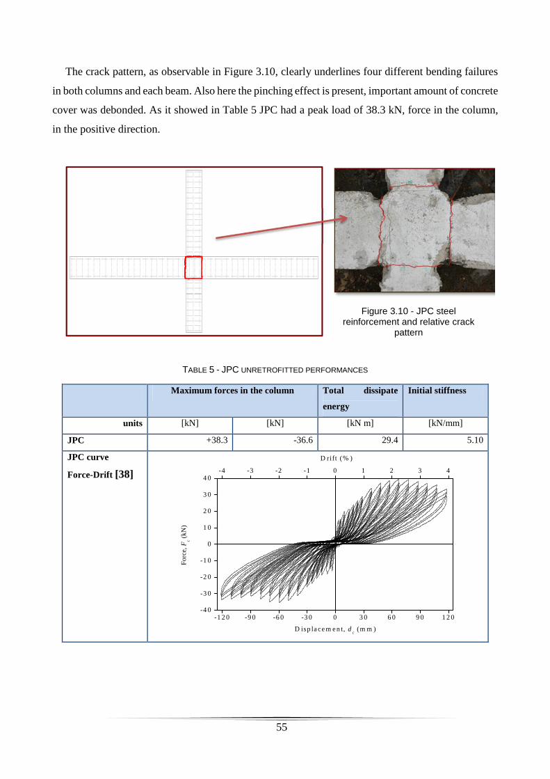
55
The crack pattern, as observable in Figure 3.10, clearly underlines four different bending failures
in both columns and each beam. Also here the pinching effect is present, important amount of concrete
cover was debonded. As it showed in Table 5 JPC had a peak load of 38.3 kN, force in the column,
in the positive direction.
Figure 3.10 - JPC steel reinforcement and relative crack
pattern
TABLE 5 - JPC UNRETROFITTED PERFORMANCES
Maximum forces in the column Total dissipate
energy
Initial stiffness
units [kN] [kN] [kN m] [kN/mm]
JPC +38.3 -36.6 29.4 5.10
JPC curve
Force-Drift [38]
-1 2 0 -9 0 -6 0 -3 0 0 3 0 6 0 9 0 1 2 0-4 0
-3 0
-2 0
-1 0
0
1 0
2 0
3 0
4 0
For
ce, F
c (kN
)
D isp lacem en t, dc (m m )
-4 -3 -2 -1 0 1 2 3 4
D ri ft (% )

56
Table 6 resumes the performance of each specimen. At maximum drift, the total energy dissipated
by JPA-3 is about 56% and 41% higher than that for JPB and JPC, respectively. Figure 3.11 shows
the dissipated energy of each specimen related to the drift.
TABLE 6 – RESUMING RESULTS
Specimen Maximum forces in the column Total dissipate
energy
Initial stiffness
units [kN] [kN] [kN m] [kN/mm]
JPA-3 +43.3 -41.8 42.4 4.33
JPB +39.5 -35.4 27.4 5.05
JPC +38.3 -36.6 29.4 5.10
Figure 3.11 – Evolution of total energy dissipation, specimens at UA [38]

57
3.3 Material characterization
3.3.1 Cementitious material
Globally three different types of cementitious materials were used. The SHCC material, low
strength mortar and shrinkage compensated self-leveling mortar.
The SHCC used in this project were developed by Esmaeeli et al [34] [36] [39] [40] at UMinho
using local material from Portugal. The SHCC characteristics are still under analysis and they will be
presented in future publication of UMinho.
In some specimens low strength mortar was used to recover the lost concrete cover. It was
characterized by means of compression test in a cubic concrete specimen of dimension 10x10x10cm3.
After 28 days a compressive strength of 30.3 MPa was obtained.
The mortar used has the commercial name SikaGrout®-213. It is shrinkage compensated self-
leveling, premixed cementitious grout with extended working time to suit local ambient temperature.
Compressive strength declared by the manufacturer is ~40 N/mm2 (at +25°C / 28 days). The reduction
of strength was obtained by adding sand to this material.

58
3.3.2 Carbon fiber reinforced elements
In this project two kinds of carbon reinforced fibers (CFRP) are used: CFRP laminates and CFRP
sheet. Those are made by S&P ® Company, have commercial name S&P ® Laminates CFK and S&P
® C-Sheet 240, respectively. The CFRP strips used have a rectangular cross section with dimension
of 1.2 mm of thickness and 10 mm of height (Figure 3.12) available in rolls of 100 m or 150 m. The
carbon fibers sheet (Figure 3.13) is available in a roll of 0.117 mm of thickness; the density is 1.7
g/cm3; Table 7 and Table 8 show their main properties.
Figure 3.12 – CFRP strips
Figure 3.13 – Carbon fibers sheet
TABLE 7- CFRP LAMINATES PROPERTIES
Property
Tensile strength at elongation 0.6%
Tensile strength at elongation 0.8%
Elastic modulus
1000 MPa
1300 MPa
165 GPa
TABLE 8 - CFRP SHEET PROPERTIES
Property
Tensile strength
Elastic modulus
Elongation at rupture
3800 MPa
240 GPa
1.55%

59
3.3.3 Epoxy adhesives
Three types of epoxy glues were used in this work. For the CFRP strips and CFRP sheet the S&P
Resin 220 and S&P Resin Epoxy 50 were used, respectively. Moreover, Sikadur®-52 Injection from
Sika® Company was used for filling the cracks.
S&P Resin 220 epoxy was used as binder in the NSM system. It is an adhesive solvent-free,
thixotropic, grey two-component specially developed from the company for bonding carbon fiber
laminates (S&P laminates CFK). The main characteristics are listed in Table 9
TABLE 9 - CHARACTERISTIC OF S&P RESIN 220
Characteristic
Density
Bending tensile strength
Compression strength
Adhesive strength (on concrete)
Adhesive strength (on S&P laminates CFK)
1.75 g/cm3
> 30 N/mm2
> 90 N/mm2
> 3 N/mm2
> 3 N/mm2
The S&P Resin Epoxy 50 is a solvent-free, transparent 2-component epoxy resin with a formulated
amine hardener. Table 10 shows the main properties.
TABLE 10 - CHARACTERISTIC OF S&P RESIN EPOXY 50
Characteristic
Density
Tensile strength (after 14 days)
Elongation at break
Pull off strength on concrete
1.11 Kg/dm3
35.8 N/mm2
2.3 %
Failure of concrete
Sikadur®-52 Injection Type N is a two part, solvent-free, low viscosity injection liquid, based on
high strength epoxy resin. It is used to fill and seal voids and cracks in structures such as bridges and
other civil engineering buildings, industrial and residential buildings, e.g. columns, beams,
foundations, walls, floors and water retaining structures. The main characteristics listed in Table 11.

60
TABLE 11 - CHARACTERISTIC OF SIKADUR®-52 INJECTION
Characteristic unit
Density
Compressive strength (According to ASTM D695-96)
Flexural strength (According to DIN 53452)
Tensile strength (According to ISO 527)
1.1 kg/dm3
52 N/mm2
61 N/mm2
37 N/mm2
3.3.4 Chemical anchors
The anchors used in the present work are produced by the HILTI® Company (Figure 3.14). Each
anchor has a diameter of 10 mm and a length of 190 mm. The material was steel 8.8. Table 12 shows
the main properties. The anchors are chemically anchored to the concrete. The company provided
washers and nuts that were used in the whole project except the washers on precast panels. Those
ones were bought bigger than HILTI’s washers in order to increase the level of priestess applied to
the anchors without damaging the SHCC. This procedure was only used in precast solution; it is due
to the irregularities in the surface of RC joint and SHCC panels. This gap between surfaces can be
drastically reduced by pressing the SHCC panels against the exiting structural elements. The
flexibility of these panels is an important benefit of SHCC.
Figure 3.14 – Anchors
TABLE 12 – MECHANICAL PROPERTIES OF ANCHORS
Properties Unit
Tensile strength
Yield stress
800 MPa
640 MPa
The Hilti ® HIT-HY 150 MAX glue is used to bond the metal anchors to concrete. It is a hybrid
adhesive mortar combining urethane methacrylate resin, hardener, cement and water (Figure 3.15).
The components are kept separate from the hardener and water by means of a dual-cylinder foil
cartridge attached to a manifold. The material properties for cured adhesive are listed in Table 13.

61
Figure 3.15 - HIT-HY 150 MAX
TABLE 13 - MATERIAL PROPERTIES FOR CURED ADHESIVE
Properties Unit
Compressive strength (ASTM C 579)
Flexural strength (ASTM C 580)
Modulus of Elasticity (ASTM C 307)
> 50 MPa
>20 MPa
> 3500 MPa
3.3.5 Strain gauges
All the strain gauges used in this work are supplied from by Tokyo Sokki Kenkyujo Co., ltd.
Two types of strain gauges were used: one of 2 mm on carbon laminates and another one of 5 mm
on old steel reinforcement and on FRP sheet.
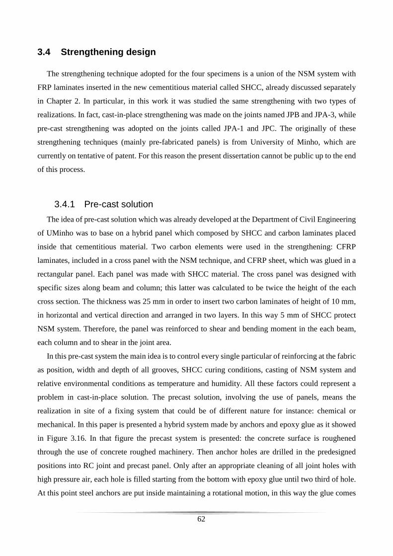
62
3.4 Strengthening design
The strengthening technique adopted for the four specimens is a union of the NSM system with
FRP laminates inserted in the new cementitious material called SHCC, already discussed separately
in Chapter 2. In particular, in this work it was studied the same strengthening with two types of
realizations. In fact, cast-in-place strengthening was made on the joints named JPB and JPA-3, while
pre-cast strengthening was adopted on the joints called JPA-1 and JPC. The originally of these
strengthening techniques (mainly pre-fabricated panels) is from University of Minho, which are
currently on tentative of patent. For this reason the present dissertation cannot be public up to the end
of this process.
3.4.1 Pre-cast solution
The idea of pre-cast solution which was already developed at the Department of Civil Engineering
of UMinho was to base on a hybrid panel which composed by SHCC and carbon laminates placed
inside that cementitious material. Two carbon elements were used in the strengthening: CFRP
laminates, included in a cross panel with the NSM technique, and CFRP sheet, which was glued in a
rectangular panel. Each panel was made with SHCC material. The cross panel was designed with
specific sizes along beam and column; this latter was calculated to be twice the height of the each
cross section. The thickness was 25 mm in order to insert two carbon laminates of height of 10 mm,
in horizontal and vertical direction and arranged in two layers. In this way 5 mm of SHCC protect
NSM system. Therefore, the panel was reinforced to shear and bending moment in the each beam,
each column and to shear in the joint area.
In this pre-cast system the main idea is to control every single particular of reinforcing at the fabric
as position, width and depth of all grooves, SHCC curing conditions, casting of NSM system and
relative environmental conditions as temperature and humidity. All these factors could represent a
problem in cast-in-place solution. The precast solution, involving the use of panels, means the
realization in site of a fixing system that could be of different nature for instance: chemical or
mechanical. In this paper is presented a hybrid system made by anchors and epoxy glue as it showed
in Figure 3.16. In that figure the precast system is presented: the concrete surface is roughened
through the use of concrete roughed machinery. Then anchor holes are drilled in the predesigned
positions into RC joint and precast panel. Only after an appropriate cleaning of all joint holes with
high pressure air, each hole is filled starting from the bottom with epoxy glue until two third of hole.
At this point steel anchors are put inside maintaining a rotational motion, in this way the glue comes

63
out and no air enters. When the epoxy is hard and the anchors are ready to develop enough strength
to fix the SHCC panel, everything is ready for the next step. At this moment new epoxy glue is used
between old concrete and precast panel. One layer is spread on the concrete surface, previously
roughed, and another layer is spread on the precast panel. Finally, until the epoxy is still workable,
the panel is put on the joint and screwed through the closure of all nuts. Through this system of
assembly it is ensured that the glue fills the empty spaces in all anchor holes of the panel and the
excess epoxy comes out from the panel sides.
Precast strengthening strategy was adopted for joints JPA-1 and JPC.
Figure 3.16 – Pre-cast panel system
3.4.1.1 CROSS PANELS
The construction of the cross panels was performed with the following tasks:
• Casting panel: the fresh SHCC was applied from the top and at the center of the formwork (Figure
3.17). In this strategy it was obtained an arrangement of the fibers in the direction parallel to the
long sides. The SHCC was covered with a plastic film (Figure 3.18), de-molded 24 hours later
and kept wet during the first 7 days in the same environmental of the RC joints.
SHCC with NSM
Nuts&Washers
Epoxy glue
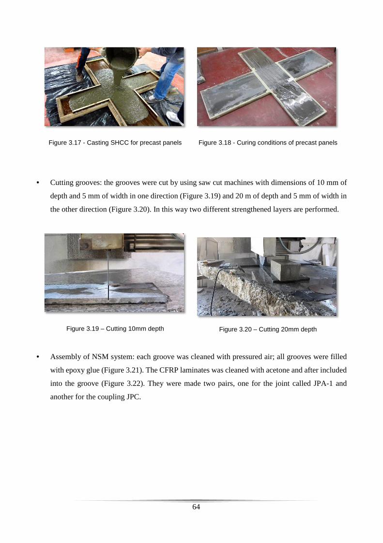
64
Figure 3.17 - Casting SHCC for precast panels
Figure 3.18 - Curing conditions of precast panels
• Cutting grooves: the grooves were cut by using saw cut machines with dimensions of 10 mm of
depth and 5 mm of width in one direction (Figure 3.19) and 20 m of depth and 5 mm of width in
the other direction (Figure 3.20). In this way two different strengthened layers are performed.
Figure 3.19 – Cutting 10mm depth
Figure 3.20 – Cutting 20mm depth
• Assembly of NSM system: each groove was cleaned with pressured air; all grooves were filled
with epoxy glue (Figure 3.21). The CFRP laminates was cleaned with acetone and after included
into the groove (Figure 3.22). They were made two pairs, one for the joint called JPA-1 and
another for the coupling JPC.

65
Figure 3.21 – Filling grooves with epoxy glue
Figure 3.22 – Cleaning of carbon FRP laminates
• Moreover the surface, the surface of the panel in contact with the existing RC joint was roughened
in order to improve the bond properties (Figure 3.23 & Figure 3.24).
Figure 3.23 – surface not completely roughened
Figure 3.24 – Roughned surface ready

66
3.4.1.2 RECTANGULAR PANELS
The second kind of panel was a HPC with rectangular shape. Eight panels were made, four longer
panels for the beams and four shorter panels for the columns. The panels were designed with
dimension such as to cover the column and the beam for a length of the plastic hinge. The thickness
was 2.5 cm. The construction procedure is the same of the cross panels previously explained however
Figure 3.25 and Figure 3.26 below show the main steps.
Figure 3.25 – Fresh selfcompact SHCC
Figure 3.26 – Rectangular panels casted and cover with plastic film

67
3.4.2 Cast-in-place solution
The cast-in-place solution is based on the idea that the same strengthening solution of precast
strategy should be made inside the concrete cover of the RC joints. For this solution it was necessary
to remove the existing concrete cover in order to be replaced by the SHCC material strengthened with
two layers of C-FRP laminates. Since each laminate has a width of 10 mm, 20 mm of concrete cover
must be assured in order to have two different layers. The existing cover ranged between 16 to 20
mm due to the irregular position of stirrups. For this reason the new cover was increased by 5 mm
(total of 25 mm) in order to safety allow the placement of the two layers of carbon FRP laminates.
In cast-in-place strategy (Figure 3.27) no primer is adopted to improve bond between old concrete
and SHCC. To increase the bond between this new material and old one chemical anchors were used.
Additionally, using the same fixing solution between precast and cast-in-place techniques allows a
better comparison in terms of results.
Cast-in-place strengthening strategy was adopted for joints JPA-3 and JPB.
Figure 3.27 – Cast-in-place system
Anchors
NSM C-bars
ECC material

68
3.4.3 General retrofitting details
Information regarding to this strengthening technique does not exist. For this reason reasonable
dimensions for the areas to be improved were adopted, twice of the cross-section width (Figure 3.28).
Figure 3.28 – Strengthened area
For the reason explained above, the same strengthening configuration was adopt for all the
specimens in the cross area (Figure 3.29). Only one difference is presents on shear strengthening of
JPC’s beams, step used about 20cm instead of 10 cm as in the others one according to J. Barros et al.
[17]. Basically, two different levels of carbon laminates are used: horizontal and vertical (Figure
3.30). In order to have a safe SHCC thickness in cast-in-place solutions, the concrete cover was
increased about 5mm.

69
Figure 3.29 – FRP laminates geometry for cross area is the same between precast and cast-in-place system
Figure 3.30 – intersection between carbon laminates
The cross faces are strengthened in this way on JPA-1, trough precast system, and on JPA-3,
through cast-in-place system. Lateral faces are not strengthened with any system.
The others joints are also strengthened in lateral faces, JPB with cast-in-place system and JPC with
precast system. On JPB concrete cover was rebuilt with SHCC and strengthened with NSM technique,
using two carbon-laminates por each face with same characteristics mentioned above (Figure 3.31).
Each laminate has a length inside the concrete between 7,5cm and 10cm.
Figure 3.31 – Lateral NSM strengthening on JPB, column is the vertical blue element

70
During the execution of holes for two of them the stirrup was met. To solve this problem a flexible
extension for the laminate was designed using carbon fiber sheet and epoxy glue S&P-50 as Figure
3.32 and Figure 3.33 show.
Figure 3.32 – fibers glued on laminate for a length of 5cm, red lines mark the borders
Figure 3.33 – Laminates with extensions ready
In order to have a different solution to compare with this one, a precast lateral strengthening was
adopted on specimen JPC. 8 SHCC rectangular panels were fabricated. The carbon strengthening
adopted in this case isn’t NSM but FRP sheet glued between concrete and SHCC as previously
performed by Esmaeeli et al. [36].
In both strengthening systems chemical anchors are designed to increase the bond between precast
panel or SHCC and old concrete. The depth was chosen in order to transfer the tensions to the core
of the concrete element and to guarantee a pre-stress of 60 Nm.
For all details regarding geometry of the entire strengthening consult the drawings attached in
annex B1, B2, B3 and B4.

71
3.5 Specimens preparation
3.5.1 Joint JPA-1: precast solution
The preparation of the joint can be divided into two main parts: the reconstruction of the joint and
the application of the strengthening. Figure 3.34 show a 3D drawing of the joint reinforced.
Figure 3.34 - 3D view of JPA-1 joint after the precast retrofitting
Joint’s reconstruction
a) Reconstruction of the corner: this work was performed using mortar SikaGrout-213 which
was prepared according to the manufacturer's instructions. This task included the following steps:
removal of damaged old concrete in the corner area and cleaning with compressed air; application of
the formwork; wet the surface; preparation of the grout; filling the formwork with grout (Figure 3.35);
and, leveling of the surface (Figure 3.36). The mortar was de-molded after one day and kept wet the
surface for next 7 days (Figure 3.37).

72
Figure 3.35 – Casting corner
Figure 3.36 – Leveling of the surface
Figure 3.37 – New corner
Figure 3.38 – Epoxy resin for injection
b) Crack selling: this step consists on filling the cracks with resin for injection in order to restore
the bond between the concrete and steel bars in the vicinity of the cracks. It was used a low-viscosity
epoxy resin SikaDur 52 Injection (Figure 3.38). The procedure adopted was not able to close the
micro cracks with thickness under 0.2-0.3mm. To seal the cracks the following main steps were
adopted: drilling of boreholes in the area of the crack (crossing them); cleaning of the holes; insertion
of small transparent hoses inside the holes; sealing the areas of the crack and around the hoses with
iron mass to prevent the resin to escape and the end injection of the resin.
Joint’s strengthening
The application of the strengthening was made by using the following steps:
a) Preparation of the concrete surface: the surface was roughened (Figure 3.39) by removing a
layer of 2-3mm of concrete with a specific hammer (Figure 3.40).
Figure 3.39 – Surface roughned
Figure 3.40 – Hilti’s hammer

73
b) Application of anchors: it was used 18 anchors chemically bonded to concrete. To
perform this step the following procedures were done: drilling the old concrete and the panel
with a hole of 12 mm of diameter; cleaning these areas with pressured air; fill the hole with the
adhesive; introduce the anchor in the hole.
Figure 3.41 – Drilling panel
Figure 3.42 – Putting the anchors
c) Application of the panel: firstly the epoxy adhesive S&P 220 was spread on the joint surface
and on the panel surface (Figure 3.43). The anchors allowed positioning the panel correctly. Then the
anchors were closed with their bolts so as to adhere the panel. In this way it was assured no air bubbles
were present (Figure 3.44). A torque of 40 N⋅m in all the anchors were applied.
Figure 3.43 – Spreading of the glue
Figure 3.44 – Joint strengthened

74
d) Rotation of the joint: after the joint recostruction of the one surface of the specimen, it was
turned and then the another surface was reconstracted with the procedures previoulsy referred. The
rotation was performed with the aid of steel chains and steel bars in order to minimize the introduction
of stresses during this phase (see Figure 3.45).
Figure 3.45 – Joint rotation

75
3.5.2 Joint JPC: precast strengthening system
The strengthening adopted for the JPC specimen was composed by “cross” hybrid panels with
CFRP strips and the rectangular hybrid panels with carbon sheet. Figure 3.46 shows the pre-cast
“cross” panels with blue color and rectangular hybrid panels in the in the corners (represented in
green color).
Figure 3.46 - 3D view of JPC joint after the precast retrofitting
The preparation of the joint can be divided into two main parts: the reconstruction of the joint and
the application of the new reinforcement. These two operations were performed in one faces, then the
specimen was turned, and the remaining surface was prepared. The joint reconstruction was made
using the following the main tasks:
a) Reconstruction of the surface: the old cover was removed and replaced with a new concrete
with the similar compressive strength. Hence it was removed a layer of 2 cm with a jackhammer
(Figure 3.47), cleaning with compressed air, filling of the crack with epoxy for injection, application
of the formwork (Figure 3.48), application of the strain gauges (Figure 3.49), wet the surface,

76
preparation of the grout, casting the new cover, leveling of the surface (Figure 3.50). The mortar was
de-molded after one day and kept wet for next 7 days.
b)
Figure 3.47 – Concrete removal
Figure 3.48 – Application of the formwork
Figure 3.49 – Application of the strain gauges
Figure 3.50 – Casting of the new concrete
The application of the new reinforcement was made with the following steps:
a) Preparation of the concrete surface: the surface was roughened removing a layer of 2-3mm of
concrete with a specific hammer in order to improve the adherence with epoxy (Figure 3.51 and
Figure 3.52).
Figure 3.51 – Top surface roughened
Figure 3.52 - Lateral surface roughened
b) Application of anchors: 18 anchors it was used to improve the bond between old and new
cementations materials (Figure 3.53). This task involve the following steps: drilling the old concrete

77
and the panel (Figure 3.54) with holes of 12 mm of diameter; cleaning with pressured air; fill the hole
with chemically glue; introduce the anchor inside the hole.
c) Application of the CFRP sheet: a carbon sheet was attached on the lateral face with epoxy
S&P 50; then the anchors were put in the same side (Figure 3.56). Two strain gauges were glued in
the same position of the longitudinal steel reinforcement (Figure 3.55).
Figure 3.53 – Putting the anchors on top surface
Figure 3.54 – Drilling of hole in the panel
Figure 3.55 – Putting of the strain gauges
Figure 3.56 – Putting of the anchors in the lateral surface
d) Application of the cross panel: firstly the epoxy S&P 220 was spread on the top surface and
lateral surfaces of the joint (Figure 3.57); then the top panel was installed (Figure 3.58). The anchors
allowed positioning the panel correctly. By applying the bolts in the anchors, the panel was properly
applied. A torque of 40 N⋅m was used to prestress the anchors.
e) Application of rectangular panels: the epoxy S&P 50 was spread on the panel surface (Figure
3.59) and on carbon sheet (Figure 3.60). In these panels similar procedure was adopted for the anchors
like in the “cross” panel (see previous step).

78
Figure 3.57 – Spreading of glue in the panel
Figure 3.58 – Installation of the panel
f) Rotation of the joint: after the joint recostruction of the one surface the specimen it was turned
and then the other one was reconstracted. The same procedure to the one described for the previous
joint, was used in the present one.
Figure 3.61 and Figure 3.62 show the final state of the joints after applying the lateral panels.
Figure 3.59 – Spreading of epoxy glue on the
carbon sheet
Figure 3.60 - Spreading of epoxy glue on the panel
Figure 3.61 – Strengthening completed
Figure 3.62 – Lateral strengthening completed

79
3.5.3 Joint JPB: cast-in-place strengthening system
A cast-in-place solution was adopted for the JPB specimen. Figure 3.63 shows the final aspect of
strengthened joint with SHCC material (grey color) and CFRP bars (white color). The anchors applied
are visible too.
Figure 3.63 – 3D strengthened
The preparation of the joint can be divided into two main parts: the reconstruction of the joint and
the application of the strengthening. These two operations were performed in one of its faces, then
the specimen was turned, and the other face was prepared. The joint reconstruction was made with
the following main tasks:
a) Reconstruction of the surface: this task requires the following steps: removal of the old
concrete cover with a jackhammer; filling of the crack with epoxy injection; application of the
formwork; application of the strain gauges; wet the surface; preparation of the SHCC (Figure 3.64),
casting the new cover (Figure 3.65 and Figure 3.66); and, leveling of the surface. The SHCC was

80
very fluid and it did not need the vibration. The SHCC was de-molded one day after casting and kept
wet for next 7 days (Figure 3.67).
b)
Figure 3.64 – Preparation of the mix
Figure 3.65 – Casting SHCC material
Figure 3.66- Casting SHCC material
Figure 3.67 - Preservation
The application of the CFRP materials was made with the following steps:
c) Cutting of the grooves: grooves were cut with 5 mm of width and 10 mm of depth in one
direction while in the other one groove of 5 mm of width and 20 mm of depth were cut. Figure 3.68
and Figure 3.69 show the final aspect of the grooves in the top and lateral faces.
Figure 3.68 – Cutting grooves on the top surface
Figure 3.69 – Cutting grooves on the lateral surface

81
d) Preparation of the CFRP material: the CFRP strips were cut with the desired dimensions, and
then they were cleaned with acetone. Special CFRP laminate bars were prepared for the grooves of
the lateral faces of the joint with carbon sheet ends (see Figure 3.70 and Figure 3.71).
e) Installation of CFRP bars: the groove was cleaned with pressured air; then, filled with epoxy
adhesive S&P 220; and, finally the CFRP bars were included into the grooves (Figure 3.72).
f) Application of the anchors: the application of the anchors followed the same procedures of
the ones described in the previous joints (see Figure 3.73).
g) Rotation of the joint: similarly to the prevoues joints, the current one was turned to conclude
the strengthening.
Figure 3.70 – Preparation of CFRP laminate with carbon sheet
Figure 3.71 – CFRP laminate with carbon sheet
Figure 3.72 – Installation of CFRP bars into the groove.
Figure 3.73 – Putting of anchors in JPB

82
3.5.4 Joint JPA-3: cast-in-place strengthening system
A cast-in-place solution was also adopted for the JPA-3 specimen. Figure 3.74 show the overall
aspect of the joint.
Figure 3.74 - 3D view of JPA-3 joint after the precast retrofitting
The preparation of the joint can be divided into two main parts: the reconstruction of the joint and
the application of the strengthening. These two operations were performed in one of faces of the joint,
then the specimen was turned, and the face was prepared. The following steps were adopted for
strengthening JPA-3 joint:
a) Reconstruction of the surface: this task requires the following steps: removal of the old
concrete cover with a jackhammer; filling of the crack with epoxy injection; application of
the formwork; application of the strain gauges; wet the surface; preparation of the mortar;
casting lateral concrete cover with mortar (Figure 3.75) and cube specimens (Figure 3.78);
casting the cross face with SHCC (Figure 3.76); and, leveling of the surface. The SHCC
was very fluid and it did not need the vibration. The SHCC and mortar were de-molded

83
one day after casting and kept wet for next 7 days (Figure 3.77). In the present one SHCC
material was used as new concrete cover of the top and bottom faces.
Figure 3.75 – Casting of normal concrete
Figure 3.76 – Casting of SHCC
Figure 3.77 - Preservation
Figure 3.78 – Cubic specimens
The application of the CFRP materials was made with the following steps:
b) Cutting of the grooves: grooves were cut with 5 mm of width and 10 mm of depth in one
direction while in the other one groove of 5 mm of width and 20 mm of depth were cut.
Figure 3.79 and Figure 3.80 and Figure 3.69 show the technique.
Figure 3.79 – Cutting grooves on JPA-3
Figure 3.80 – Grinders

84
c) Preparation of the CFRP material: the CFRP strips were cut with the desired dimensions,
and then they were cleaned with acetone.
d) Installation of CFRP bars: the groove was cleaned with pressured air; then, filled with
epoxy adhesive S&P 220; and, finally the CFRP bars were included into the grooves
(Figure 3.81 and Figure 3.82).
Figure 3.81 – View 1 of CFRP bars into the groove
Figure 3.82 - View 2 of CFRP bars into the groove
a) Application of the anchors: the application of the anchors followed the same procedures of
the ones described in the previous joints (Figure 3.83 and Figure 3.84).
b) Rotation of the joint: similarly to the prevoues joints, the current one was turned to
conclude the strengthening.
Figure 3.83 – Drilling the hole on the top surface
Figure 3.84 – Putting the anchors on JPA-3

85
Chapter 4
Results
This chapter presents and analyses the results of the RC joints after being strengthened and tested.
The specimens were tested with the same test setup, previously described in the Chapter 3. Curve
force versus displacement, maximum forces in both directions, increment in term of maximum forces,
initial stiffness, dissipate energies, degradation of maximum force during 3 cycles and failure modes
are presented and discussed.
4.1 Force versus Displacement
The following four figures present the relationships between the horizontal displacements at the
top of the column (δc [mm]) and the applied lateral forces (Fc [kN]) for all the tested performed with
the RC joints after being strengthened. These figures also include the test results of the corresponding
specimen before the strengthening (original specimens).
As it can be seen, for the joints JPA-1R (Figure 4.1), JPB-R (Figure 4.3) and JPC-R (Figure 4.4)
the repairing and strengthening strategies adopted led to relevant increment in term of load carrying
capacity, when compare to the relative reference. The increment, as Table 14 shows, was about 22%
and 61% for the case of JPA-1R and JPB-R, respectively. In the JPA-3R the strengthening was almost
the same of JPA-1R; however the behavior after test was lower in terms of maximum load carrying
capacity, when compared with reference specimen (Figure 4.2).
JPA-1R (Figure 4.1) was repaired and later strengthened using the precast solution with two
“cross” panels. When compared with the reference, JPA-1R registered an increment in terms of load
carrying capacity of about 22% in both directions, as shown in Table 14. After the peak load the load
carrying capacity did not significantly drop remaining in levels lower but close to maximum force.
For this reason the test was continued with two more displacement levels of ±150 mm and ±190 mm.
During these cycles the axial load in the column was increased a little for safe conditions. Only JPC-
R was not subjected to these two displacements.

86
Figure 4.1 – Force (Fc) versus displacement (δ) response for the specimens JPA-1R and JPA-3
Figure 4.2 - Force (Fc) versus displacement (δ) response for the specimens JPA-3R and JPA-3
-60
-40
-20
0
20
40
60
-200 -150 -100 -50 0 50 100 150 200
Fc
[kN
]
δc [mm]
JPA-1R
JPA-3
-60
-40
-20
0
20
40
60
-200 -150 -100 -50 0 50 100 150 200
Fc
[kN
]
δc [mm]
JPA-3R
JPA-3

87
Figure 4.3 – Force (Fc) versus displacement (δ) response for the specimens JPB-R and JPB
Figure 4.4 – Force (Fc) versus displacement (δ) response for the specimens JPC-R and JPC
-60
-40
-20
0
20
40
60
-200 -150 -100 -50 0 50 100 150 200
Fc
[kN
]
δc [mm]
JPB-R
JPB
-60
-40
-20
0
20
40
60
-200 -150 -100 -50 0 50 100 150 200
Fc
[kN
]
δc [mm]
JPC-R
JPC

88
An interesting behavior of JPA-3R strengthened specimen (see Figure 4.2) is observed only in
elastic phase, after the specimen did not reached the peak load observed in the reference specimen
(no strengthened), being the decrement of the lateral force equals to at about 5% and 9%, respectively,
for the positive and negative directions. The reason for this behavior could be related with the strategy
adopted during the repairing phase. This specimen before the strengthening presented a significant
damage level in the interior part of the joint. During the repairing phase several cracks with non-
negligible width were tried to be sealed with the previously refereed epoxy adhesive. This epoxy was
injected with a low pressure. So this procedure may not adequately repair the joint. Even if the
strengthening amount of the retrofitting adopted on this specimen is comparable with that used on
JPA-1R, the final behavior of JPA-3R reveals the critical importance of the repairing step, sealing
cracks in particular.
As previously referred, Figure 4.3 presents the response JPB-R and its reference specimen (JPB)
in terms of lateral horizontal forces and corresponding. The strengthened specimen presented really
interesting results, increasing the load carrying capacity without a sudden fall of the resistance level
after the peak. In fact the RC joint reached the maximum forces of 52.7 kN in positive and -57.1 kN
and negative directions, with an increment respect to the reference one at about 33% and 61%,
respectively. The strengthening system used for this specimen was cast-in-place in all faces. This can
explain the high reached values during the test.
Finally, Figure 4.4 presents the relationship between horizontal lateral forces and corresponding
displacements for the JPC-R and its reference, JPC. An increment for the load carrying capacity of
retrofitted specimen was registered; in fact the joint reached maximum forces of 57.2 kN in positive
and -56.8 kN in negative direction, with an increment respect to the reference at about 50% and 55%,
respectively. After the pick load the strength dropped a little for some cycle levels and it descended
definitely to the same values of the reference. Although this joint presented the best old steel
reinforcement, the strengthening strategy adopted was not able to keep higher load than the reference
values. The brittle failure can explain this suddenly load drop.
Table 14 presents the main results in terms of maximum force reached in both directions for
retrofitted specimens (JPA-1R, JPA-3R, JPB-R and JPC-R) and also for the references specimens
(JPA-3, JPB and JPC). In the same table is also showed the force increment for the peak load, when
compared with the reference specimen.

89
Table 14 – Main results obtained in the tested specimens
Fc,max+ Increment δFc,max
+ Fc,max- Increment δFc,max
-
specimen [kN] % [mm] [kN] % [mm]
JPA-3 43,2 43,2 -41,8 -69,5
JPA-1R 52,6 22% 79,6 -51,2 22% -69,2
JPA-3 43,2 43,2 -41,8 -69,5
JPA-3R 40,8 -5% 50,3 -38,0 -9% -50,1
JPB 39,5 67,2 -35,4 -59,6
JPB-R 52,7 33% 50,1 -57,1 61% -70,3
JPC 38,2 97,2 -36,6 -87,7
JPC-R 57,2 50% 49,4 -56,8 55% -79,1
Table 15 shows the strength degradation for the cycles corresponding to the peak load. As it can
be seen, JPA-1R reached higher value in terms of peak load when compared with JPA-3; moreover
the strength degradation in the two consecutive cycles was lesser than the reference degradation. Only
4% after the second cycle and 7% after the third cycle for JPA-1R, while for the reference the
degradation was about 9% and 11%, respectively. A similar behavior was observed for the case of
the negative direction.
JPA-3R showed comparable degradations with the relative references in both direction. JPB-R
presented a better behavior of this parameter in the negative direction, reaching in the third cycle only
9% instead of 13% of the reference while comparable degradation in the positive direction.
Despite of the JPC-R specimen has reached the maximum absolute force between all the tested
specimens, significant strength degradation was observed for the peak load cycles. In fact the
degradation for the next two cycles was about 20% in positive direction and 29% in negative
direction, whereas the reference reached a maximum absolute value of 12%.

90
Table 15 – Strength degradation at the peak load for all the tests
cycle Force Degradation cycle Force Degradation
Specimen [n°] [kN] % [n°] [kN] %
JPA-3
34 43,2 31 -41,8
35 39,3 9% 32 -39,1 7%
36 38,4 11% 33 -37,9 9%
JPA-1R
34 52,6 31 -51,2
35 50,3 4% 32 -49,4 3%
36 48,9 7% 33 -48,2 6%
JPA-3
34 43,2 31 -41,8
35 39,3 9% 32 -39,1 7%
36 38,4 11% 33 -37,9 9%
JPA-3R
25 40,8 25 -38,0
26 38,1 7% 26 -35,2 7%
27 36,5 11% 27 -33,5 12%
JPB
31 39,5 28 -35,4
32 37,0 6% 29 -32,1 9%
33 35,8 9% 30 -30,6 13%
JPB-R
25 52,7 31 -57,1
26 50,4 4% 32 -54,3 5%
27 47,8 9% 33 -52,2 9%
JPC
40 38,2 37 -36,6
41 36,7 4% 38 -34,2 7%
42 33,8 12% 39 -32,8 10%
JPC-R
25 57,2 34 -56,8
26 48,5 15% 35 -44,6 22%
27 45,7 20% 36 -40,2 29%
4.2 Stiffness
An important parameter for evaluating a repairing technique is initial stiffness observed in the
repaired specimens. Table 16 shows the initial stiffness of each repaired specimen and the
corresponding reference specimen. For specimens JPA-1R and JPC-R the increment of initial
stiffness is about 22% and 23% respectively. On the other hand JPA-3R and JPB-R, the initial
stiffness decreased at about 20% and 24%, respectively, when compared with the reference
specimens.
The procedure for restoring was the same for all the specimens, however due to the impossibility
to use high pressure systems for injecting the resin to seal the existing micro cracks in the JPB-R and
JPA-3R specimens may contributed for this lower behavior. Another reason could be related to the
strengthening system adopted for the specimens. In fact both specimens that presented higher stiffness
were retrofitted with precast solutions. The use of “industrial” preparation of panels increased the

91
effective cross-section areas of the beams and columns composing the joint. In addition to that, the
higher quality control of this system associate to the use of epoxy to fix the panels to concrete could
also provide a higher initial stiffness for precast system.
Table 16 – Initial Stiffness
Ei Increment
Specimen [kN/mm] %
JPA-3 4,33
JPA-1R 5,27 22%
JPA-3 4,33
JPA-3R 3,48 -20%
JPB 5,05
JPB-R 3,82 -24%
JPC 5,10
JPC-R 6,28 23%
4.3 Dissipated energy
Table 17 shows the results in term of dissipated energy. The values were calculated using the
trapezium rule to estimate the area under the force versus displacement curves shown in Figure 4.1,
Figure 4.2, Figure 4.3 and Figure 4.4. An increase in terms of dissipated energy was observed for all
the strengthened specimens when compared with the reference ones. The highest increases were about
84% up to 94% for the case of JPC-R and JPB-R, respectively. JPA-3 presented a slight increase of
about 5%.
In terms of dissipated energy, all the reinforced joints presented higher values of average 51 kNm
Table 17 – Dissipated energy
Ed Increment
specimen [kNm] %
JPA-3 42,4
JPA-1R 52,3 23%
JPA-3 42,4
JPA-3R 44,5 5%
JPB 27,4
JPB-R 53,3 94%
JPC 29,4
JPC-R 54,0 84%

92
4.4 Specimens failure modes
Figure 4.5 shows the damages observed in the JPA-1R strengthened joint at end of the test. In the
drawing the red lines represent the cracks on the specimen while the blue lines represent the micro-
cracks observed on the SHCC panels. In order to see the micro-cracks on SHCC surface, synthetic
oil was sprayed at the beginning of the test. For the JPA-1R joint the following damages can be
summarized: on the beam one crack arose in the same position of existing one crack at level 50 mm
(Figure 4.6) while two new cracks arose at ends of the panel at level 60 mm.
Figure 4.5 – JPA-1R’s crack pattern
Figure 4.7Diagonals cracks appeared in the middle of panel for a displacement of 60 mm. Figure
4.7 shows the “cross” important cracks and several micro-cracks in the joint region. The cracks were
well visible on the precast panel (Figure 4.6) and on the concrete surface.
Figure 4.6 – Cracks on the beam
Figure 4.7 – Diagonal cracks in the joint region

93
No cracks were observed in the column. The corners presented the detachment of the old concrete
cover at level 150 mm (Figure 4.8). The damage on the SHCC panel was characterized by several
micro-cracks. Figure 4.9 shows the micro-cracks in the vicinity of the longitudinal carbon laminates.
The multi-cracks demonstrate the good collaboration between the two different materials used in this
system.
Figure 4.8 - Detachment of the old concrete cover
Figure 4.9 – Micro-crack on the SHCC panel along longitudinal carbon laminate
Figure 4.10 shows the damage observed in the JPC-R after being tested. Four major cracks on the
beam two cracks close to joint region (Figure 4.11 and Figure 4.12) and two cracks at the end of the
panel were perfectly identified. Figure 4.13 also shows the “diagonal” cracks on the joint region,
composed by micro-cracks in the prefabricated panel. No cracks were observed in the column.
Figure 4.10 – JPC-R’s crack pattern

94
Several micro-cracks were spread on the panel surface. Figure 4.14 shows the micro-cracks in the
SHCC panel along the longitudinal carbon laminate location.
Figure 4.11 – JPC-R after test
Figure 4.12 – Bending failure in the beam
Figure 4.13 – Bending failure in the beam and several micro-cracks in the joint area
Figure 4.14 – Micro-cracks in SHCC panel along longitudinal carbon laminate location

95
The Figure 4.15 shows the main damages observed for the JPA-3R prototype at end of the test. This
specimen presented a main damage characterized by cracks in the joint region and a large amount of
micro-cracks along the longitudinal laminates location and at the middle of joint. No significant
cracks formed along the column and beam.
Figure 4.15 – JPA-3R’s crack pattern
Figure 4.17 shows details about the failure at the joint region. As can be seen in Figure 4.18 several
cracks occurred on the lateral faces. Comparing the Figure 4.16 with the Figure 4.18 it is possible to
note the different configuration of the crack on the SHCC material and on normal concrete. Figure
4.19 show the failure of the longitudinal CFRP laminate due to the detachment of the concrete.
Figure 4.16 – Crack on the top surface, JPA-3
Figure 4.17 – Failure of the joint region in JPA-3

96
Figure 4.18 – Crack on the lateral surface, JPA-3
Figure 4.19 – Failure of the longitudinal bars, JPA-3
The Figure 4.20 shows the final state of JPB-R specimen after being tested. The specimen
presented a damage characterized by cracks in the joint region and a large amount of micro-cracks
along the longitudinal laminates location and in the middle of joint, as it can be seen in Figure 4.21
and Figure 4.22. The crack pattern observed in the original specimen (non-strengthened)
characterized by bending failure at the columns, moved to the joint area for the case of the
strengthening prototype.
Figure 4.20 – JPB-R’s crack pattern
The diagonal cracks occurred in the same position of the diagonal laminates location. The bottom
surface presented the same damage of the top surface (Figure 4.22).

97
Figure 4.21 – Crack on the top surface, JPB joint
Figure 4.22 – Crack on the bottom surface, JPB joint

98

99
Chapter 5
Conclusions
In the present work four beam-column joints reinforced with plane rebars previously tested under
cyclic loading up to the failure, were repaired and strengthened according to NSM technique and
using SHCC material as part of retrofitting. Two different approaches were adopted: precast and cast-
in-place systems. Two specimens were strengthened using the first approach: in one joint only bottom
and top faces were strengthened (JPA-1R) whereas in the other one joint in all faces were strengthened
(JPC-R). The others two specimens were strengthened using the cast-in-place approach, and similar
strengthening strategy, i.e. in one prototype only bottom and top faces were strengthened (JPA-3R)
while in the other one specimen all faces were strengthened (JPB-R).
In terms of force versus displacement relationships, JPC-R, JPB-R and JPA-1R presented higher
values of for the peak load when compared with the reference specimens. On the other side, JPA-3R
presented a lower peak load when compared with the reference one. The explanation for this weak
behavior could be associated to the use of a non-proper repairing procedure for sealing the cracks of
the original joints. In spite of that, good results were obtained in terms of dissipated energy and in
terms of failure mode. In fact the failure did not occurred in columns. All the others joints presented
increasing in terms of peak load in both directions. JPC-R showed a relevant decreasing in term of
strength degradation in both directions for the peak load cycles in spite of this specimen presented
the greatest peak load value.
JPB-R and JPC-R presented higher dissipated energy than the reference specimens. In terms of
failure modes important results were also observed. In fact in all the non-strengthened joints, bending
failure modes were observed in all the columns; in the retrofitted joints failure was not observed in
all the columns. However for specimen JPA-1, JPA-3 and JPB the crack pattern observed in the
columns of the original specimens, after the tests of strengthening specimens the type of failure
moved to the joint area. The explanation to this fact could be associated to the insufficient shear
strengthening and poor confinement of joint. Before strengthening, specimen JPC presented failures
in columns and beams, after that the failures in columns moved to the beams. The reason could be
related to the better confinement of the joint area due to presence in the joint area of stirrups, detail
not present for the other samples.

100
JPB-R and JPC-R were strengthened in all faces using cast-in-place and precast system,
respectively. JPA-1R was strengthened only in bottom and top faces using precast system and also it
presented the lower old steel reinforcement between those. However JPA-1R almost reached the
maximum peak load of the other two, obtained the higher initial stiffness with JPC-R and improved
the failure mode.
In general the results showed that if the existing cracks are properly sealed, both precast and cast-
in-place strategies can bring very interesting performances. However more work needs to be done in
this field with more specimens in order to validate this strategies. Also, the introduction of non-
damaged specimens and joints reinforced with ribbed bars in future researches can be very useful in
order to see the actual benefits that retrofitting can give.

101
Bibliography
[1] INGV, 2013. [Online]. Available: www.ingv.it. [Accessed 07 2013].
[2] ISTAT, 2013. [Online]. Available: www.istat.it. [Accessed 2013].
[3] S. Pampanin, G. Calvi and M. Moratti, "SEISMIC BEHAVIOUR OF R.C. BEAM-
COLUMN JOINTS," 2002.
[4] A. C. 440, "Guide for the Design and Construction of Externally Bonded FRP Systems
for Strengthening Concrete Structures," 2008.
[5] "Norme Tecniche per le Costruzioni," 2008.
[6] C. –. C. d. S. p. l. P. e. l. d. N. T. r. a. costruzioni, "Istruzioni per la Progettazione,
l'Esecuzione ed il Controllo di Interventi di Consolidamento Statico mediante l'utilizzo di
Compositi Fibrorinforzati - Materiali, strutture di c.a. e di c.a.p., struttire murarie," 2012.
[7] Progettaregroup. [Online].
[8] D. A. Lawrence C. Bank, "Analysis of RC beams strengthened with mechanically
fastened," 2006.
[9] E. c. 8, "Progettazione delle strutture per la resistenza sismica".
[10] L. D. Lorenzis and J. Teng, "Near-surface mounted FRP reinforcement: an emerging
technique for strengthening structures," 2006.
[11] M. P. Burke and D. L. B. &. M. Green, "Structural performance of near surface
mounted FRP strengthened concrete slabs at elevated temperatures," 2008.
[12] L. T. M. B. I. V. I.A. Sharaky, "Effect of different material and construction details on
the bond behaviour of NSM FRP bars in concrete," 2012.
[13] A. Balsamo, F. Nardone, I. Iovinella, F. Ceroni and M. Pecce, "Flexural strengthening
of concrete beams with EB-FRP," 2012.
[14] D. A. C. Lawrence, "Analysis of RC beams strengthened with mechanically fastened
FRP (MF-FRP) strips," 2006.
[15] J. Sena-Cruz, J. Barros, M. Coelho and L. Silva, "Experimental and numerical study
of distinct techniques to strengthen beams failing in bending under monotonic loading".

102
[16] A. F. J.A.O.Barros, "Flexural strengthening of concrete beams with CFRP laminates
bonded into slits," 2004.
[17] B. S. D. J. L. J.A.O, "Efficacy of CFRP-based techniques for the flexural and shear
strengthening of concrete beams," 2006.
[18] L. D. L. A. Rizzo, "Behavior and capacity of RC beams strengthened in shear with
NSM FRP reinforcement," 2007.
[19] H. Tanarslan, "The effects of NSM CFRP reinforcements for improving the shear
capacity of RC beams," 2010.
[20] T. Telford, "Comite Euro-International du Beton, RC frames under earthquake loading
: state of the art report / Comité Euro-International du Béton," 1996.
[21] C. M. G. M. &. G. F. G.M. Verderame, "I meccanismi deformativi di colonne in c.a.
con barre lisce," 2005 - 2008.
[22] M. P. E. N. Gaetano Russo, "Indagine Sperimentale su Nodi Esterni Trave-Pilastro
Armati con Barre".
[23] "http://www.slideshare.net/amerald24/rpair-and-retrofit-on-beam-and-column-
joints#btnNext," [Online].
[24] A. SM and J. JO, "Strength of Reinforced Concrete Frame Connections Rehabilitated
by Jacketing," 1993.
[25] E. E. &. F. Danesh, "The Behavior of 3D RC Beam-Column Joint Strengthened by the
GFRP Layers and Steel Cage Under Bi-directional Cyclic Loading," 2007.
[26] M. Costas P. Antonopoulos and Thanasis C. Triantafillou, "Experimental investigation
of FRP-Strengthened RC Beam-Column Joints," 2003.
[27] P. F. J. M. J. S. C. H. V. J. B. A. C. Mário Coelho, "Seismic strengthening of beam-
column joints with multi-directional CFRP laminates," 2011.
[28] [. R. d. S. M. Ferreira, "Pilares de Betao armado renforcados com laminados de fibras
de carbonio," 2000.
[29] P. F. J. S. C. J. B. Mário Coelho, "Reforço sísmico de nós de pórtico em betão armado
com laminados multidirecionais de CFRP," 2011.
[30] A. E. Naaman, "High performance fiber reinfroced cement composites: classification
and applications".

103
[31] V. Li, "Engineered cementitious composites (ECC) - Tailored composites through
micromechanical modeling".
[32] V. c. Li and G. Fischer, "Reinforced ECC - An evolution from materials to structures".
[33] K. Yun Yong, F. Gregor, L. Yun Mook and L. Victor, "Mechanical performance of
sprayed engineered cementitious composite using wet-mix shotcreating precess for repair
applications," 2004.
[34] E. Esameel, M. Elizabeth and B. Joaquim, "Strain hardening fibre reinforced cement
composite for the flexural strengthening of masonry elements of ancient structures," 2012.
[35] L. Victor, M. DK and W. HC, "Matrix design for pseudo strain-hardening fiber
reinforced cementitious composites," 1995.
[36] E. Esmaeeli, J. Barros and H. Baghi, "Hybrid Composite Plates (HCP) for shear
strengthening of RC beams," 2013.
[37] EuroCode2, "EN 1992-1-1:2004," 2004.
[38] C. Fernandes, J. Melo, H. Varum and A. Costa, "Cyclic behavior of substandard RC
beam-column joints with plain bars," Aveiro, 2013.
[39] E. E, B. J and G. D, "Preliminary assessment on the development of cost-competitive
PVA-fiber reinforcement mortar," ISISE, Guimaraes, 2011.
[40] B. J, E. E, M. E and H. D, "Flexural strengthening of masonry members using advanced
cementitious materials.," in 2nd international RILEM conference on strain hardening
cementitious composites (SHCC2-Rio), Rio de Janeiro, 2011.
[41] J. B. M. C. a. L. S. J. Sena-Cruz1, "Experimental and numerical study of distinct
techniques to strengthen beams failing in bending under monotonic loading".
[42] K. Y. S. S. H. K. Teroaka M, "An estimation of ductility in interior beam-column sub-
assemblages of reinforced concrete frames. J Soc Mater Sci," 1996.
[43] "Circolare 2 febbraio, 2009 n°617, istruzione per l’applicazione delle NTC-2008".
[44] H. Stang and V. Li, "Classification of fiber reinforced cementitious materials for
structural applications," 2004.
[45] M. Lepech and V. Li, " Large scale processing of Engineered Cementitious
Composite," ACI Materials Journal, 2008.
[46] I. STRUTTURALE, "Eurocode 8 - Design of structures for earthquake resistance - Part
3: Assessment and retrofitting of buildings," 2005.

104
[47] "Circolare 2 febbraio, 2009 n°617, istruzione per l’applicazione delle NTC-2008,"
2009.
[48] A. E. H. R. A. Dalalbashi, "Plastic hinge relocation in RC joints as an alternative
method of retrofitting," 2012.

105
ANNEXES

CR
EATO
CO
N L
A V
ERSI
ON
E D
IDA
TTIC
A D
I UN
PR
OD
OTT
O A
UTO
DES
KCREATO CON LA VERSIONE DIDATTICA DI UN PRODOTTO AUTODESK
CR
EATO
CO
N LA
VERSIO
NE D
IDA
TTICA
DI U
N PR
OD
OTTO
AU
TOD
ESKCREATO CON LA VERSIONE DIDATTICA DI UN PRODOTTO AUTODESK

CR
EATO
CO
N L
A V
ERSI
ON
E D
IDA
TTIC
A D
I UN
PR
OD
OTT
O A
UTO
DES
KCREATO CON LA VERSIONE DIDATTICA DI UN PRODOTTO AUTODESK
CR
EATO
CO
N LA
VERSIO
NE D
IDA
TTICA
DI U
N PR
OD
OTTO
AU
TOD
ESKCREATO CON LA VERSIONE DIDATTICA DI UN PRODOTTO AUTODESK

CR
EATO
CO
N L
A V
ERSI
ON
E D
IDA
TTIC
A D
I UN
PR
OD
OTT
O A
UTO
DES
KCREATO CON LA VERSIONE DIDATTICA DI UN PRODOTTO AUTODESK
CR
EATO
CO
N LA
VERSIO
NE D
IDA
TTICA
DI U
N PR
OD
OTTO
AU
TOD
ESKCREATO CON LA VERSIONE DIDATTICA DI UN PRODOTTO AUTODESK

CR
EATO
CO
N L
A V
ERSI
ON
E D
IDA
TTIC
A D
I UN
PR
OD
OTT
O A
UTO
DES
KCREATO CON LA VERSIONE DIDATTICA DI UN PRODOTTO AUTODESK
CR
EATO
CO
N LA
VERSIO
NE D
IDA
TTICA
DI U
N PR
OD
OTTO
AU
TOD
ESKCREATO CON LA VERSIONE DIDATTICA DI UN PRODOTTO AUTODESK

CR
EATO
CO
N L
A V
ERSI
ON
E D
IDA
TTIC
A D
I UN
PR
OD
OTT
O A
UTO
DES
KCREATO CON LA VERSIONE DIDATTICA DI UN PRODOTTO AUTODESK
CR
EATO
CO
N LA
VERSIO
NE D
IDA
TTICA
DI U
N PR
OD
OTTO
AU
TOD
ESKCREATO CON LA VERSIONE DIDATTICA DI UN PRODOTTO AUTODESK

CR
EATO
CO
N L
A V
ERSI
ON
E D
IDA
TTIC
A D
I UN
PR
OD
OTT
O A
UTO
DES
KCREATO CON LA VERSIONE DIDATTICA DI UN PRODOTTO AUTODESK
CR
EATO
CO
N LA
VERSIO
NE D
IDA
TTICA
DI U
N PR
OD
OTTO
AU
TOD
ESKCREATO CON LA VERSIONE DIDATTICA DI UN PRODOTTO AUTODESK

CR
EATO
CO
N L
A V
ERSI
ON
E D
IDA
TTIC
A D
I UN
PR
OD
OTT
O A
UTO
DES
KCREATO CON LA VERSIONE DIDATTICA DI UN PRODOTTO AUTODESK
CR
EATO
CO
N LA
VERSIO
NE D
IDA
TTICA
DI U
N PR
OD
OTTO
AU
TOD
ESKCREATO CON LA VERSIONE DIDATTICA DI UN PRODOTTO AUTODESK

CR
EATO
CO
N L
A V
ERSI
ON
E D
IDA
TTIC
A D
I UN
PR
OD
OTT
O A
UTO
DES
KCREATO CON LA VERSIONE DIDATTICA DI UN PRODOTTO AUTODESK
CR
EATO
CO
N LA
VERSIO
NE D
IDA
TTICA
DI U
N PR
OD
OTTO
AU
TOD
ESKCREATO CON LA VERSIONE DIDATTICA DI UN PRODOTTO AUTODESK