
MASTER THESIS 2011 - uia.brage.unit.no
107
1 This Master’s Thesis is carried out as a part of the education at the University of Agder and is therefore approved as a part of this education. However, this does not imply that the University answers for the methods that are used or the conclusions that are drawn. University of Agder, 2012 Faculty of Technology Department of Engineering Title Rotating tools for quick connection of drill pipe (Spinner) By Lawk Fryad Farji Supervisor Kjell G. Robbersmyr Henning Grosaas Kjetil Nyvold Subject area Mechatronics
Transcript of MASTER THESIS 2011 - uia.brage.unit.no

1
This Master’s Thesis is carried out as a part of the education at the
University of Agder and is therefore approved as a part of this
education. However, this does not imply that the University answers
for the methods that are used or the conclusions that are drawn.
University of Agder, 2012
Faculty of Technology
Department of Engineering
Title
Rotating tools for quick connection of drill pipe (Spinner)
By
Lawk Fryad Farji
Supervisor
Kjell G. Robbersmyr
Henning Grosaas
Kjetil Nyvold
Subject area
Mechatronics

2
Abstract
In this project a rotating tool for quick connection of drill pipe has been designed. It satisfies
the following three operation cases:
First, is to grip the different sizes of drill pipe.
Second, is to spin of the upper joint of drill pipe.
Third, is to make up and break out a torque.
In addition the connecting system of drill pipe is dimensioned and set up as a simulation
model.
The following have been accomplished:
Product specification and generation of concepts.
Dimension of the hydraulic system.
Selection of hydrauilc component.
Selection of mechanical component .
Synchronization of two hydraulic motors.
Synchronization of two hydraulic cylinders.
Design and FEM analysis of the spinner.
Building a prototype of the spinner.
The spinner is designed to handle all normal ranges of drill pipe from motor
with gearing system ensures that the spinner is
and a torque of 2309N.m
This high torque is higher than that which can be found at the
present, and this may eliminate the need for the torque wrench as the gap between the drill
pipes will be reduced or possibly eliminated. The main purpose is to reduce operating time
and compact the tool.
The spinner includes the four hydraulically synchronized driven rollers to give a better grip on
the drill pipe. The machine made to provide optimal grip and permit limited rotation along the
vertical connection axis. This rotation allows the rollers to adjust onto the drill pipe as they
clamp onto it providing optimal grip.
Responsible and supervisor at UiA: Prof. Kjell G. Robbersmyr
Supervisor at NOV: Henning Grosaas and Kjetil Nyvold
Carried out at: NOV, Kristiansand

3
Nomenclature
F = Force
Fthp = Theoretical periphery force, Pinion
Fthw = Theoretical periphery force, Gear
Fcl = Clamping force
Pb = Equivalent dynamic bearing load
Ϭbp = Bending stress, Pinion
Ϭbg = Bending stress, Gear
Ϭop = Contact stress, Pinion
Ϭog = Contact stress, Gear
Ts = Spinning torque
Tm = Motor moment
Nsp = Spinning speed
nm = Motor speed
Cr = Chrome
Ni = Nickel
Mo = Molybdenum
MF = Main Function
SF = Sub Feature
DS = Different Solutions
LVDT = Linear Variable Differential Transformer
CVG = Control Valve Group
DCV = Directional Control Valve
CNC = Computer Numerical Control

4
List of Contents
Abstract ...................................................................................................................................... 2 1. Introduction ........................................................................................................................ 6 2. Spinner wrench ................................................................................................................... 7
2.1 Product specification ................................................................................................... 7 2.2 Function alternatives .................................................................................................... 9
2.2.1 Objectives ............................................................................................................. 9
2.2.2 Approach .............................................................................................................. 9
2.3 Partial Solution description and grading ................................................................... 10 2.3.1 Objectives ........................................................................................................... 10
2.3.2 Approach ............................................................................................................ 16
2.4 Concepts .................................................................................................................... 17 2.5 Evaluation of concepts ............................................................................................... 19
2.6 From concept to final design ..................................................................................... 20 2.7 Choice of components ............................................................................................... 21
3. Hydraulic System ............................................................................................................. 22 3.1 Hydraulic System Components ................................................................................. 22
3.2 Static Analysis ........................................................................................................... 23
3.2.1 Calculation and dimension of spur gear ............................................................. 24
3.2.2 Calculation of spinning torque and speed .......................................................... 27
3.2.3 Calculation of clamping force ............................................................................ 27
3.2.4 Calculation and dimension of cylinder ............................................................... 27
3.2.5 Calculation of bearing ........................................................................................ 29
3.3 Dynamic Analysis ...................................................................................................... 30
3.3.1 Simulation model .............................................................................................. 30
3.3.2 Simulation Results .............................................................................................. 34
4. Control System ................................................................................................................. 35 4.1 Utility Control ............................................................................................................ 35
4.2 Control of CVG Proportional Valve .......................................................................... 35 4.3 Control of Hydraulic Motor ....................................................................................... 35 4.4 Control of hydraulic cylinder .................................................................................... 36 4.5 Control of Torque ...................................................................................................... 37
4.6 Control of vertical movement and bump ................................................................... 37 5. Solid Works simulation FEM analysis ............................................................................. 38 6. Prototype .......................................................................................................................... 40 7. Conclusion ........................................................................................................................ 41
Acknowledgements .................................................................................................................. 42 Bibliography ............................................................................................................................. 43 List of Figures .......................................................................................................................... 44
List of Tables ............................................................................................................................ 45 Appendix .................................................................................................................................. 46
Appendix A - Project Description ........................................................................................ 47 Appendix B - Motor Catalogue Sauer – Danfoss ................................................................. 49 Appendix C - Flow divider sun hydraulic ............................................................................ 51 Appendix D - Pmc servi cylinder servic .............................................................................. 54 Appendix E - CVG Control Valve Group ............................................................................ 57

5
Appendix F - Tannhjul Kapittel 9 ........................................................................................ 66
Appendix G - MASKINKONSTRUKTION II, Beregning av sylindriske tannhjul med rette
tenner .................................................................................................................................... 76 Appendix H - Rullingslager Kapittel 7 ................................................................................ 90
Appendix I – Sfåfiska rullager ............................................................................................. 97 Appendix J – Gantt Chart ................................................................................................... 104 Appendix K – DRAWING ................................................................................................. 106

6
Chapter 1
1. Introduction
Connecting pipe down the well bore on a drilling rig is a tough, hazardous job and typically
done in a dangerous working environment best done by unmanned tools to avoid casualties.
The traditional way of connecting pipe on drilling floor was by manual labourer called
Floorhands [9]. Of the 2 Floorhands, the lead tong hand “ ” s the break out
tongs used to break apart the threaded connections of the drill pipe. The chainhand, who is
one of the floorhands, “ - g ” c g
the connection. These activities are the reason for many human accidents and casualties. The
solution to avoid these problems is to remove the traditional human roughnecks, and replace
them with machines operated from a safe location.
The automated connection and disconnection of a wide variety of drill pipe can be as efficient
as if done by human labor. This machine will be safe and reliable.
Furthermore a machine failing or not being able to operate up to the specified requirements
can cause the rig to come to a halt. A small breakdown will have a large economic impact.
More important than economic aspect is that by replacing manual labour with machines the
safety of the rig workers will be maintained.
NOV (National Oilwell Varco) is one of the leading worldwide providers of drilling
equipment to the oil and gas industry producing equipment to drill ships, semi submersibles
and fixed installations. One such equipment is the roughneck. A NOV Roughneck consists of
two parts, the upper part is called spinner and the lower part is called the torque wrench. The
spinner spins the upper joint in/out of the drill pipe and then the torque wrench makes up
torque to give a better connection of the drill pipe. The upper part (spinner) cannot give
enough torque to spin the drill pipe.
To spin the drill pipe in/out, the spinner must have a high grip force and a high torque to be
able to spin the drill pipe. This is solved by using two motors with gearing system.
A spinning wrench engages the stem of the upper joint of the drill pipe and spins the upper
joint of the drill pipe until it is connected/ disconnected from the lower joint.
This tool allows the drill pipe to be spun up to get the smallest possible gap between the pipes.
The spinner is hydraulically operated and it incorporates a roller drive.
This work has the following primary objectives:
- Calculation of the hydraulic and the mechanical system.
- The design part includes the dimensioning of the mechanical and the hydraulic circuit
of the griper and the spinner design system.
- The virtual design and simulation of a spinning wrench.
- Design of the spinner wrench and verification of the structural calculation by using
Solid Works Simulation.
- To develop and produce the prototype of the spinner machine.
7
Chapter 2
2. Spinner wrench
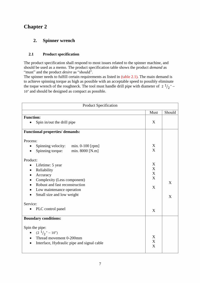
2.1 Product specification
The product specification shall respond to most issues related to the spinner machine, and
should be used as a memo. The product specification table shows the product demand as
“must” and the product desire “ ”.
The spinner needs to fulfill certain requirements as listed in (table 2.1). The main demand is
to achieve spinning torque as high as possible with an acceptable speed to possibly eliminate
the toque wrench of the roughneck. The tool must handle drill pipe with diameter of ⁄
and should be designed as compact as possible.
Product Specification
Must Should
Function:
Spin in/out the drill pipe
X
Functional properties/ demands:
Process:
Spinning velocity: min. 0-100 [rpm]
Spinning torque: min. 8000 [N.m]
Product:
Lifetime: 5 year
Reliability
Accuracy
Complexity (Less component)
Robust and fast reconstruction
Low maintenance operation
Small size and low weight
Service:
PLC control panel
X
X
X
X
X
X
X
X
X
X
Boundary conditions:
Spin the pipe:
⁄
Thread movement 0-200mm
Interface, Hydraulic pipe and signal cable
X
X
X

8
Product Specification
Must Should
Project plan:
Project start: 13.01.2011
Design: 4 weeks
Simulation and calculation 6 weeks
Prototyping: 4 weeks
Hand over report : 31.05.2012
X
X
X
X
X
Cost:
Development cost: Not specified
(Dis)Assembly/ Manipulation:
Change of roller
X
Standard:
NS-EN 1993-1-1 Design of steel structures- General rules
NS-EN 1993-1-8 Beregning av knutepunkter og forbindelser
X
X
Safety:
Safe to avoid human and material damage
X
Environment:
Withstand harsh environment (outdoor)
X
Table 2.1 – Product specification

9
2.2 Function alternatives
2.2.1 Objectives
To generate dozens of concepts, and find a unique solution to this challenge, a concept tree
has been made. This section describes function alternatives with the selected option that has
been used for the spinner wrench. By defining the design problem in terms of a Main
Function (MF) the construction work will start. The complex design problem will be split into
manageable pieces in terms of Sub Function (SF).
2.2.2 Approach
The main function (MF) of the spinner wrench is to make up and break out drill pipe. The
necessary functions to be able to spin the different size of pipes are divided into Sub Features
(SF). Different Solutions (DS) to each Sub Feature is presented in (Figure 2.1)
The main function table needs to be made to generate the different concept.
Figure 2.1 – Function alternatives
MF
Spinner wrench
SF.1
Clamp Pipe
DS.1.1
Cylinder
DS.1.2
El. powered liear actuator
DS.1.3
Gear
DS.1.4
Cam shaft
SF.2
Generate Clamp Force
DS.2.1
Hydraulic
DS.2.3
Electronic
DS.2.4
Air
SF.3
Measure Clamp Force
DS.3.1
Load cell
DS.3.2
Pressure transducer
DS.3.3
Pressure transmiter
SF .4
Rotate Pipe
DS.4.1
Roller
DS.4.2
Conveyor chain
DS.4.3
Conveyor belt
SF.5
Generate Rotation
DS.5.1
Hydraulic Motor
DS.5.2
Electro Motor
DS.5.3
Wheel
SF.6
Measure Velocity
DS.6.1
Rotary Encoder
SF.7
Measure Bump
DS.7.1
Active Thread compensation
DS.7.1
Passive Thread compensation
10
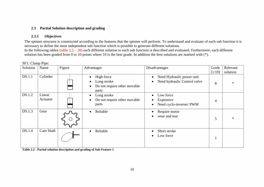
2.3 Partial Solution description and grading
2.3.1 Objectives
The spinner structure is constructed according to the features that the spinner will perform. To understand and evaluate of each sub function it is
necessary to define the most independent sub function which is possible to generate different solutions.
In the following tables (table 2.2 – 28) each different solution to each sub function is described and evaluated. Furthermore, each different
solution has been graded from 0 to 10 points where 10 is the best grade. In addition the best solutions are marked with (*).
SF1: Clamp Pipe:
Solution Name Figure Advantages Disadvantages Grade
[1/10]
Relevant
solution
DS.1.1 Cylinder
High force
Long stroke
Do not require other movable
parts
Need Hydraulic power unit
Need hydraulic Control valve 8 *
DS.1.2 Linear
Actuator
Long stroke
Do not require other movable
parts
Low force
Expensive
Need cyclo-inverter/ PWM 4
DS.1.3 Gear
Reliable Require motor
wear and tear 5
*
DS.1.4 Cam Shaft
Reliable Short stroke
Low force 1
Table 2.2 - Partial solution description and grading of Sub Feature 1

11
SF2: Generate Clamp Force:
Solution Name Figure Advantages Disadvantages Grade
[1/10]
Relevant
solution
DS.2.2 Hydraulic
No manual labour
Accurate force
Requires power
Requires help of mechanic
9 *
DS.2.3 Electric
No manual labour
Can be used in high power
application
Require power
Complex (electronic device)
8 *
DS.2.4 Air
No manual labour Requires power for compressor
Requires help of mechanic
Not accurate force 5
Table 2.3 - Partial solution description and grading of Sub Feature 2

12
SF3: Measure Clamp Force:
Solution Name Figure Advantages Disadvantages Grade
[1/10]
Relevant
solution
DS.3.3 Force and
Load cell
Integrated signal conditioning
circuitry.
Standard output signal 4-20
mA
Requires mechanical
accommodation to place the load
cell in the structure 5
DS.3.2 Pressure
transmitter
Feature additional reset and
calibration options
Calibrate the dumping of the
output signal
Integrated signal conditioning
circuitry.
Standard output signal 4-20
mA
Not interchangeable between
different manufacturers
8 *
DS.3.1 Pressure
transducer
Changes the physical variable
pressure into a quantity that
can be processed electrically
Interchangeable between
different manufacturers
Gives an unamplified signal
requiring signal conditioning
circuitry
7 *
Table 2.4 - Partial solution description and grading of Sub Feature 3

13
SF4: Rotate Pipe:
Solution Name Figure Advantages Disadvantages Grade
[1/10]
Relevant
solution
DS.4.1 Roller
Reliable
Flexible rotation
Easy to change
Better grip
Do not require other movable
parts
wear and tear
7 *
DS.4.2 Conveyor
chain
Reliable
Makes noise
Require other movable parts
wear and tear
4 *
DS.4.3 Conveyor
belt
Easy to use
Reliable
Require other movable parts
Not safe
wear and tear 3
Table 2.5 - Partial solution description and grading of Sub Feature 4

14
SF5: Generate Rotation:
Solution Name Figure Advantages Disadvantages Grade
[1/10]
Relevant
solution
DS. 5.1 Hydraulic
motor
No manual labour
Reliable
Requires power
8 *
DS.5.2 Electric
motor
Reliable
Full torque at 0 RPM
No transmission is required
Power configurations can be
done in software
Heavy
Requires power
Inability to operate at low speed
7 *
DS.5.3 Wheel
Reliable
Manual labour 0
Table 2.6 - Partial solution description and grading of Sub Feature 5

15
SF6: Measure Velocity:
Solution Name Figure Advantages Disadvantages Grade
[1/10]
Relevant
solution
DS. 6.1 Rotary
Encoder
Reliable
Output is a binary value
proportional to the angle of the
shaft
Supplies a certain number of
pulses for each shaft
revolution.
8 *
Table 2.7 - Partial solution description and grading of Sub Feature 6
SF7: Measure Bump:
Solution Name Figure Advantages Disadvantages Grade
[1/10]
Relevant
solution
DS. 7.1 Active thread
compensation
Safety and performance
Cost saved due to not
needing a physical
prototype
Complex
Needs Hardware-in-the-loop 8 *
DS.7.2 Passive thread
compensation
Safety and performance
Simple
Needs hydraulic accumulator
8 *
Table 2.8 - Partial solution description and grading of Sub Feature 7

16
2.3.2 Approach
To generate a different idea it is necessary to generate several concepts which there are also
used different solutions for the various partial functions.
The best graded alternative solution for each sub feature in the previous tables, has been
chosen and evaluated as an acceptable basis to generate the different concept.
SF1: Clamp Pipe
o DS.1.2 - Hydraulic cylinder
o DS.1.4 - Gear
SF2: Generate Clamp Force
o DS.2.2 - Hydraulic
o DS.2.5 - Electronic
SF3: Measure Clamp Force
o DS.3.1 - Pressure transducer
o DS.3.2 - Pressure transmitter
SF4: Rotate Pipe
o DS.4.1 – Roller
o DS.4.1 – Conveyor chain
SF5: Generate Rotation
o DS.5.1 – Hydraulic motor
o DS.5.1 – Electro motor
SF6: Measure Velocity
o DS.6.1 – Rotary Encoder
SF7: Measure Bump
o DS.7.1 – Active thread compensation

17
2.4 Concepts
A design concept is more specific than an idea, but less specific than a layout or drawing of a
product. Usually, concepts are best described by an annotated sketch.
A full concept for a product defines all the key features, functions and characteristics of a
design. The concept of the spinner captures the essential purpose of the product, with enough
detail that all other engineers can work out the product.
To generate the spinner wrench concepts the solutions found suitable in the evaluation of the
partial solution (ref. Table 3.1 to 3.10) has been used. Below there are three concepts
generated to make spinner equipment:
For concept 1, the spinner wrench machine consists of two hydraulic cylinders equipped with
rollers in the rod end. These cylinders are mounted to a U-formed frame (Fig. 2.2). The object
of using a hydraulic cylinder on each side is to provide a firm clamp in order to keep the drill
pipe in the well center. The holder of the rollers is formed to adapt to a variety of drill pipe
dimensions.
The cylinders are actuated by means of a HPU and control valve, while the motor can either
be actuated by a HPU and a control valve, or electrically. The force and velocity are measured
by a pressure transmitter and rotary position sensor respectively.
Figure 2.2 – Schematic connection of concept one
For concept 2, the spinner wrench machine consists of two gears equipped with rollers on the
end of retention brackets that are mounted on the sprocket side, (Fig. 2.3). Both gears and
rollers are driven by a hydraulically or electrically actuated motor. The force and velocity are
measured by a pressure transmitter and a rotary position sensor respectively.
Figure 2.3 - Schematic connection of concept Two
For concept 3, the spinner machine utilizes a hydraulic cylinder to grab onto the drill pipe,
and a chain drive system to rotate it. The hydraulic cylinder is connected at the far end of two
interconnected frames (Fig. 2.4). These frames can be described as elongated and

18
asymmetrical with a rectangular shape on one side and a bulge in the middle of the other side.
The bulged part of the two frames is connected to each other using a bolt allowing rotation of
both frames around the longitudinal axis of the bolt.
On the opposite side of where the cylinder is mounted, one roller is placed on each frame.
While gripping onto the drill pipe, these rollers will be in contact with it. A third roller is
mounted on the motor axle and a fourth smaller roller is mounted on the right hand side above
the motor for the purpose of tightening the chain.
During operation the spinner machine is moved into position (Fig. 2.4) and the cylinder
extrudes pushing the far end sides of the frames resulting in a motion which clamps the drill
pipe between the two rollers. This clamping mechanism is reminiscent of how scissors work.
With the drill pipe firmly in contact with the chain, the motor will run the chain drive and thus
rotate the drill pipe. The force and velocity are measured by a pressure transmitter and rotary
position sensor respectively.
Figure 2.4 - Schematic connection of concept three

19
2.5 Evaluation of concepts
The different concepts were evaluated with regard to function and construction.
The concepts were given points from 1 to 5 z c ’ “
cc ” 5 “very g ”
Evaluation of Function:
Criteria evaluation Concept 1 Concept 2 Concept 3 Ideal
Reliability 4 3 3 5
Complexity 4 3 2 5
Frame rigidity 4 3 4 5
Adaptivity 4 2 4 5
Sum: 16 11 13 20
Relative value: 0.80 0.55 0.65 1 Table 2.9 – Function evaluation
Concept 1 scored best in the function evaluation.
Evaluation of Construction:
Criteria evaluation Concept 1 Concept 2 Concept 3 Ideal
Size 4 4 2 5
Stiffness 4 3 3 5
Assembly 4 3 3 5
Sum: 8 7 5 10
Relative value: 0.80 0.70 0.5 1 Table 2.10 – Construction evaluation
Concept 1 scored best in the construction evaluation.
Concept one scored best in each case, so the “Concept One” will be chosen.
After the evaluation is finished and the concept is selected, the construction work will
continue by varying the structure and shape to achieve the most optimal solution and design.
The change of structure and design will be described in the next section.

20
2.6 From concept to final design
Overall this design was chosen due to its compactness while in storage and its ability to
provide optimum grip whilst providing all the necessary functionalities for connecting drill
pipes.
The final design incorporates the best features of the previously proposed concepts into one
compact and functional design. This design include the 4 hydraulically driven rollers from
concepts 1 and 2, as this setup was deemed to give better grip on the drill pipe. Like the other
two concepts the motor is placed on top of two rollers driving two gears attached to the rollers
themselves.
In both ends of the rollers two heart-shaped plates are attached. The plates are then mounted
on retention brackets with bearings to permit limited rotation along the vertical connection
axis. This rotation allows the rollers to adjust onto the drill pipe as they clamp onto it
providing optimal grip.
The retention brackets in this design are movable by two hydraulic cylinders. This saves
space compared with concept 1 due to it being able to retract and thus decrease its overall
width. The brackets are mounted on rods which function as tracks allowing the brackets to
v y cy ’ g c
the whole machine and are stationary.
During operation, the main structure, as seen in Figure 3.5 and as described above, moves into
position with the retention brackets in the wide open position. Then the clamping procedure
starts whereby the hydraulic cylinders retract to grip onto the drill pipe. Sensors will feedback
the force to a controller in order to determine when the rollers are firmly in contact with the
drill pipe. The rollers will now start spinning and sensors will again feedback torque data to a
controller for the motor. When a certain level a torque is reached, the motor stops, and the
retention brackets are brought out again into the wide open position.
Figure 2.5 - Final design

21
2.7 Choice of components
After choosing the final concept the following components were chosen.
Name Description: Image: Qty.
Roller
Stainless Steel
4
Pressure transmitter [1]
Pressure transmitter
2
Roller Bearing [6]
Bearing series number 22313 CC
8
SKF dry sliding bearing
[13]
M material 2mm wall thickness,
220mm length
4
Gear
15 CrNi 6
4
Hydraulic Motor with
Pinion [12]
OMT 315 cm3 from Sauer
Danfoss
2
Hydraulic Cylinder [11]
Cylinder LHA25 B/G 110mm
from pmc servi
2
Table 2.11 – Choice of Components

22
Chapter 3
3. Hydraulic System
Hydraulic systems can be found today in a wide variety of applications, from small assembly
processes to integrated steel and most aircraft use hydraulics in the braking systems and
landing gear. Hydraulic systems use an incompressible fluid, such as oil or water, to transmit
forces from one location to another within the fluid. Hydraulics enable the operator to
accomplish significant work (lifting heavy loads, turning a shaft, drilling precision holes, etc.)
with a minimum investment in mechanical linkage through the application of P c ’ ,
which states:
"Pressure in a confined fluid is transmitted undiminished in every direction, and acts with
equal force on equal areas, and at right angles to the container walls". [2]
Static analyses are first conducted for the configuration of the hydraulic system. This gives a
quick overview of system performance and component dimensions. The calculations will also
serve as references during the dynamic analysis in which simulation software is used. The aim
of the dynamic analysis is to validate the dimensions calculated in the static analysis.
3.1 Hydraulic System Components
The hydraulic system consists of two hydraulic cylinders, servo valve, flow divider and two
hydraulic motor which is driven by hydraulic supplier existing on the rig.
A hydraulic cylinder is a mechanical actuator that is used to give a unidirectional force
through a unidirectional stroke. The hydraulic cylinder consists of a cylinder barrel, in which
a piston connected to a piston rod moves back and forth.
A hydraulic motor is a mechanical actuator that converts hydraulic pressure and flow into
torque and angular displacement (rotation). The hydraulic motor uses pressurized fluid to
rotate the active drum in this project to compensate heave motion and hoisting the payload to
the seabed.
To assure the same speed of two hydraulic systems (actuators or motors) independently of
their loads, the flow dividers [7] must be used. Flow dividers split flow in one direction
according to some ratio, into two flow paths independent of pressure in each path and
combine flow in the opposite direction.
An electro-hydraulic servo valve is an electrically operated valve that controls how hydraulic
fluid is ported to the hydraulic motor. Hydraulic valves are used in a system to start, stop and
direct fluid flow to compensate for the load disturbance and keep the regulated process
variable as close as possible to the desired velocity and torque.
A gear is a rotating machine part having cut teeth, which mesh with another toothed part in
order to transmit torque. To achieve a desired torque to spin the drill pipe, the spur gear has
been used.
A bearing is a machine element designed to fix, guide or hold moving parts and to reduce
friction. Bearing allow constrained relative motion between two or more parts, typically

23
rotation or linear movement. The spinning and clamping drill pipe, gives both radial and axial
load applied on bearing.
3.2 Static Analysis
The static analysis begins with the hydraulic system configuration fitted for the mechanical
system. Since the variable in the mechanical system is determining the required force to
clamp the pipe, the hydraulic performance configuration is found according to these. This
chapter is about the dimensioning and modeling of these elements.
The method of analysis is using the required torque which is given in the spinner
specification, to calculate and determine components fitted for this configuration in following
order gear, bearing, hydraulic cylinder(s), hydraulic motor(s) and servo valve(s). Calculation
equations are used from a hydraulic compendium [2]. This section will briefly describe the
calculation of these components.
To determine the size of the hydraulic motor DM, calculation of the motor displacement
DM,min (cm3/rev) is needed. The equation below is used to determine this component:
MDM
2min, 3.1
To determine the diameter of the hydraulic cylinder, calculation of the cylinder piston area
A(m2) is needed. The equation bellow is used to determine this component:
The necessary cylinder piston area:
F
3.2
The necessary cylinder diameter:
4d 3.3
The size of the servo valve is determined by calculating the needed motor flow, QM (l/min).
The motor flow is calculated by the following calculation:
vM
MM
M
nDQ
3.4
Where: Mn : The motor speed
vM : Volumetric efficiency of the motor
The servo valve is chosen according to motor flow. The choice is CVG30 (300 l/min). The
valve will operate with a valve pressure (P, A, B, LS) 350 bar. The valve has spool position
control (LVDT).

24
3.2.1 Calculation and dimension of spur gear
To achieve a desire torque of 8000N.m and spin the different size of drill pipes, it is necessary
to use gear to transfer the torque. The roller which has been used to spin the different size of
drill pipes has a diameter of 164mm, so the outside diameter of gear should not exceed this
diameter. To design a suitable gear which adapts a roller, the gear module has assumed to
4mm.
3.2.1.1 Geometrical conditions of spur gear
The gear module, number of tooth of the pinion and number of tooth of gear wheel has been
assumed to (4mm, 13 and 34) respectively, and according to gear compendium capital 9. [3],
the dimension of pinion and gear was found.
Modul mmm 4
Width factor 18
Tooth width mb mmb 72
Number of tooth of pinion 131 Z
Number of tooth of wheel 342 Z
Circular Pitch mp mmp 57.1
Addendum mha 0.1 mmha 4
Dedendum mhb 0.1 mmhb 4
Tooth high mh 2 mmh 8
Circular pitch mSn 05.02
mmSn 083.6
Pitch diameter of the pinion 11 ZmdP mmdP 521
Outside diameter of the pinion bO hZmd 211 mmdO 601
Root diameter of the pinion bR hZmd 211 mmdR 411
Pitch diameter of the wheel 22 ZmdP mmdP 1362
Outside diameter of the wheel bO hZmd 222 mmdO 1442
Root diameter of the wheel bR hZmd 222 mmdR 1282

25
3.2.1.2 Spur gear tooth bending stress
There are two types of high stress on the teeth, the tensile and compressive stresses due to
bending of the tooth. The compressive stress has a greater magnitude due to the radially
inward component of the tooth force Ft . The bending stress is cyclic as it occurs once per
revolution of the gear and will, thus, lead to a potential fatigue failure.
The Lewis formula has been used to calculate the bending stress.
According to table 4.6 from compendium (MASKINKONSTRUKSJON II) [4], the overload
factor is:
Over load factor 1ak
According to table 4.8 from compendium (MASKINKONSTRUKSJON II) [4], the tooth
factor is:
Tooth factor pinion 9.2p
Tooth factor wheel 6.2g
When a gear wheel is rotating the gear teeth come into contact with some degree of impact.
To allow for this a velocity factor (kv) is to be find.
Pitch line velocity s
m52.2
According to table 4.6 from compendium (MASKINKONSTRUKSJON II) [4], the drive
factor is:
Drive factor s
m10
Dynamic factor
vk 25.1vk
The motor type OMT 315 cm3 from Sauer Danfoss [5] see page 36, has been chosen. This
motor has a max. output torque of 950 Nm and 1140 Nm intermittent operation.
Motor moment mNTm 950
Motor speed rpmnm 380
Radius of drill pipe mmRpipe 127
Radius of the wheel 2
2P
g
dR mmRg 68
Radius of the pinion 2
1P
P
dR mmRg 26
26
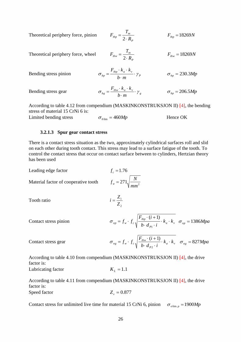
Theoretical periphery force, pinion P
m
thpR
TF
2 NFthp 18269
Theoretical periphery force, wheel P
m
thwR
TF
2 NFthw 18269
Bending stress pinion P
vathp
bpmb
kkF
Mpbp 3.230
Bending stress gear g
vathw
bgmb
kkF
Mpbp 5.206
According to table 4.12 from compendium (MASKINKONSTRUKSJON II) [4], the bending
stress of material 15 CrNi 6 is:
Limited bending stress Mpb 460lim Hence OK
3.2.1.3 Spur gear contact stress
There is a contact stress situation as the two, approximately cylindrical surfaces roll and slid
on each other during tooth contact. This stress may lead to a surface fatigue of the tooth. To
control the contact stress that occur on contact surface between to cylinders, Hertzian theory
has been used
Leading edge factor 76.1cf
Material factor of cooperative tooth 2
271mm
Nf w
Tooth ratio 2
1
Z
Zi
Contact stress pinion va
P
thp
cwop kkidb
iFff
1
)1( Mpaop 1386
Contact stress gear va
P
thw
cwog kkidb
iFff
2
)1( Mpaog 827
According to table 4.10 from compendium (MASKINKONSTRUKSJON II) [4], the drive
factor is:
Lubricating factor 1.1LK
According to table 4.11 from compendium (MASKINKONSTRUKSJON II) [4], the drive
factor is:
Speed factor 877.0vZ
Contact stress for unlimited live time for material 15 CrNi 6, pinion Mppo 1900.lim

27
Contact stress for unlimited live time for material 15 CrNi 6, pinion Mpgo 1900.lim
Safety factor 25.1oV
Allowable contact stress pinion, gear vL
o
thw
gap ZkV
, Mpagap 4.1466,
The contact stress for both pinion and gear is lower than the allowable stress Hence OK
3.2.2 Calculation of spinning torque and speed
The required torque to spinn the drill pipe is 8000N.m,
Spinning Torque rolle
pipe
p
g
msR
R
R
RTT
24 mNTs 3.7696
Spinning Speed pipe
rolle
g
p
mspR
R
R
Rnn
2 mNnsp 81.93
3.2.3 Calculation of clamping force
From the maximum torque for the largest pipe dimension, the necessary force to clamp the
drill pipe could be found.
Friction coefficient, lubricated surfaces 16.0
Clamp force
pipe
s
clR
TF kNFcl 75.348
3.2.4 Calculation and dimension of cylinder
To determine the cylinder diameter equation 3.2 – 3.3 respectively has been used. We assume
the pressure to be 250bar.
Pressure bar250
Areal of cylinder
cl
c
F 2015.0 mc
Cylinder diameter
c
cd
4
mmdc 139
From standard cylinder data blade pmc servi [10]
Piston length mmx 243
Cylinder Threaded head mmU 75
28
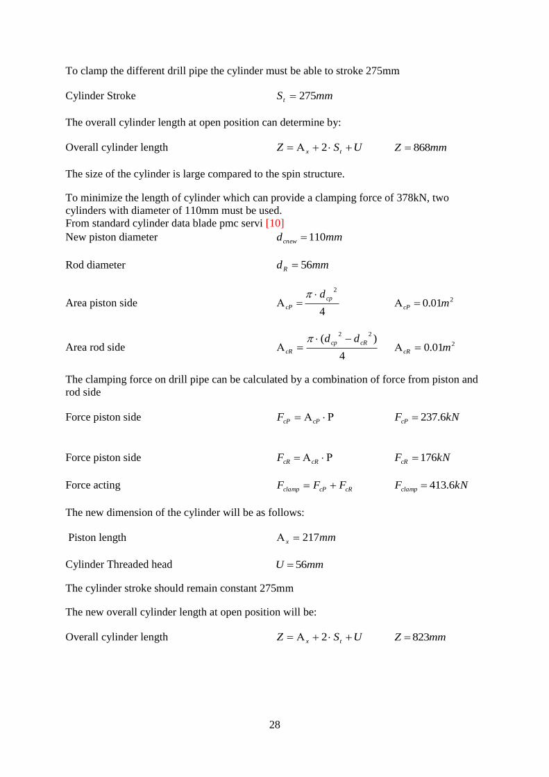
To clamp the different drill pipe the cylinder must be able to stroke 275mm
Cylinder Stroke mmSt 275
The overall cylinder length at open position can determine by:
Overall cylinder length USZ tx 2 mmZ 868
The size of the cylinder is large compared to the spin structure.
To minimize the length of cylinder which can provide a clamping force of 378kN, two
cylinders with diameter of 110mm must be used.
From standard cylinder data blade pmc servi [10]
New piston diameter mmdcnew 110
Rod diameter mmdR 56
Area piston side 4
2
cp
cP
d
201.0 mcP
Area rod side 4
)(22
cRcp
cR
dd
201.0 mcR
The clamping force on drill pipe can be calculated by a combination of force from piston and
rod side
Force piston side cPcPF kNFcP 6.237
Force piston side cRcRF kNFcR 176
Force acting cRcPclamp FFF kNFclamp 6.413
The new dimension of the cylinder will be as follows:
Piston length mmx 217
Cylinder Threaded head mmU 56
The cylinder stroke should remain constant 275mm
The new overall cylinder length at open position will be:
Overall cylinder length USZ tx 2 mmZ 823

29
3.2.5 Calculation of bearing
There are two types of loads acting on roller during the spinning operation Radial and Axial
load. A radial load: is a load producing by clamping force and applied perpendicular to the
shaft axis. An axial (thrust) load: is a load producing by the weight of the spinner and applied
parallel to the shaft axis. The bearing must resist these loads.
From rolling lager compendium (RULLELAGER) Kapittel 7 [5]
Theoretical life time 120010 hL drive hour
Shaft speed min
94
sn
Life time (mill.rev) 6
10
1010
60 sh nLL
68.6710 L
Number of bearing 8bN
Number of carry bearing 4baN
Weight of Spinner assumed to 1000kg kgWs 1000
Design load 81.9 ss WF kNFs 10
Radial load component b
cl
rN
FF kNFr 34.47
Axial load component ba
s
aN
FF kNFa 5.2
Relation between Axial and radial load r
a
raF
FR , 053.0, raR
According to table spherical roller bearing [6] for bearing with 65mm inner diameter:
Relation between Axial and radial load 35.0e
Bearing radial factor 1X
Bearing axial factor 9.11 Y
From equation of equivalent dynamic bearing load for spherical roller bearing [6]
Equivalent dynamic bearing load ar FYFP 1 If eF
F
r
a
ar FYFP 267.0 If eF
F
r
a

30
In this case eF
F
r
a kNP 1.52
Dynamic carry number 310LPC kNC 3.212
To choose the bearing which can resist this dynamic load and not have a larger diameter than
the roller, Double row spherical roller bearing should be used. From SKF bearing data sheet
we choose bearing series number 22313 CC which has the outer diameter of 140mm, inner
diameter of 65 and C = 253kN. The term consisting of five layers numbers describing the
series, where the two last indicates the inner diameter x5 and after codes indicate the bearing
characteristics.
3.3 Dynamic Analysis
The aim of the dynamic analysis is to be able to analyze the system under dynamic
conditions. This allows the validation of the initial component dimensions from the static
analysis. Wherever important discrepancies occur, the design must be adjusted for by
increasing or decreasing component dimensions.
Specific objectives in this section include:
To use the desired torque to spin the drill pipe
Set up a simulation model to test the hydraulic system
Validate the initial dimensions found in the static analysis
The approach to analyzing the system is using simulation software called SimulationX. A
Simulation X model is set up based on the dimensions calculated by hand. Having done this,
simulations of model are performed to see if the components calculated in the static analysis
hold up.
3.3.1 Simulation model
This section is about creating the Simulation X model of the hydraulic motor which is
controlled by a proportional directional control valve(s). The purpose of the hydraulic circuit
is to choose the suitable servo valve to operate the motor, which gives the required torque to
spin the upper joint of drill pipe. To do so the motor(s) and cylinder(s) must operate according
to the command signal of the proportional directional control valve CVG. Figure 3.1-a
illustrates these circuits.
In the simulation model of the motor, the model has been simplified by using a flow source
and a variable throttle valve instead of the CVG valve as shown in Figure 3.1. The highest
and lowest required torque of 7696N.m and 2309N.m respectively to spin the drill pipe is
modeled by a source component. The gar ratio is also modeled for the largest and smallest
diameter of drill pipe. The control signal block control the flow in to the flow source and
throttle valve respectively
The flow through the valve can be calculated by equation 3.1
puACQ ddA
2)(
3.1
Where

31
dC : Discharge coefficient
: Density
: Pressure drop across the valve (54, compensator spool) [8]
dA : Discharge area
)(u : Control signal
In the simulation model of the cylinder seen in Fig. 3.1-b, the CVG has been modeled in an
alternative way by using a 4/3-way directional control valve (DCV) and making sure the
pressure drop over it is constant which also ensures a constant flow through it. This is done by
g c c (“ c ”) y 3 bar above the
cylinder piston side pressure. This command is w “ c ” c
g “ ” c c c 2 c
x v y c I c ’ v
return orifice separately since it is modeled within the 4/3-way directional control valve.
The elements required for these circuits are shown in table 3.1-3.2
a) b) Figure 3.1 – Hydraulic circuit of motor in Simulation X using a) a flow source, and b) 4/3-way DCV.
32
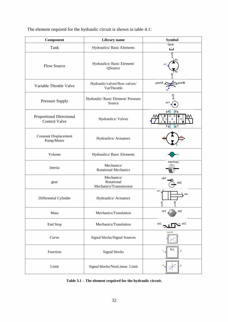
The element required for the hydraulic circuit is shown in table 4.1:
Component Library name Symbol
Tank Hydraulics/ Basic Elements
Flow Source Hydraulics/ Basic Element/
QSource
Variable Throttle Valve Hydraulic/valves/flow valves/
VarThrottle
Pressure Supply Hydraulic/ Basic Element/ Pressure
Source
Proportional Directional
Control Valve Hydraulics/ Valves
Constant Displacement
Pump/Motor Hydraulics/ Actuators
Volume Hydraulics/ Basic Elements
Inertia Mechanics/
Rotational Mechanics
gear
Mechanics/
Rotational
Mechanics/Transmission
Differential Cylinder Hydraulics/ Actuators
Mass Mechanics/Translation
End Stop Mechanics/Translation
Curve Signal blocks/Signal Sources
Function Signal blocks
Limit Signal blocks/NonLinear. Limit
Table 3.1 – The element required for the hydraulic circuit.
33
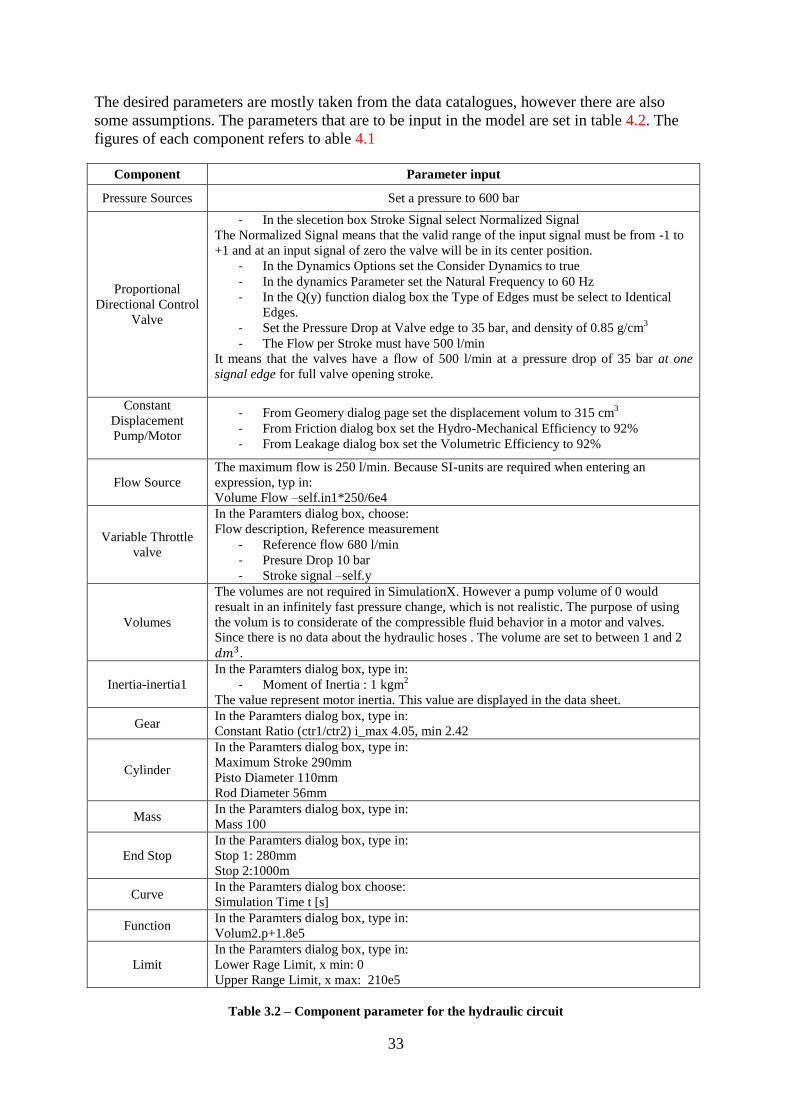
The desired parameters are mostly taken from the data catalogues, however there are also
some assumptions. The parameters that are to be input in the model are set in table 4.2. The
figures of each component refers to able 4.1
Component Parameter input
Pressure Sources Set a pressure to 600 bar
Proportional
Directional Control
Valve
- In the slecetion box Stroke Signal select Normalized Signal
The Normalized Signal means that the valid range of the input signal must be from -1 to
+1 and at an input signal of zero the valve will be in its center position.
- In the Dynamics Options set the Consider Dynamics to true
- In the dynamics Parameter set the Natural Frequency to 60 Hz
- In the Q(y) function dialog box the Type of Edges must be select to Identical
Edges.
- Set the Pressure Drop at Valve edge to 35 bar, and density of 0.85 g/cm3
- The Flow per Stroke must have 500 l/min
It means that the valves have a flow of 500 l/min at a pressure drop of 35 bar at one
signal edge for full valve opening stroke.
Constant
Displacement
Pump/Motor
- From Geomery dialog page set the displacement volum to 315 cm3
- From Friction dialog box set the Hydro-Mechanical Efficiency to 92%
- From Leakage dialog box set the Volumetric Efficiency to 92%
Flow Source
The maximum flow is 250 l/min. Because SI-units are required when entering an
expression, typ in:
Volume Flow –self.in1*250/6e4
Variable Throttle
valve
In the Paramters dialog box, choose:
Flow description, Reference measurement
- Reference flow 680 l/min
- Presure Drop 10 bar
- Stroke signal –self.y
Volumes
The volumes are not required in SimulationX. However a pump volume of 0 would
resualt in an infinitely fast pressure change, which is not realistic. The purpose of using
the volum is to considerate of the compressible fluid behavior in a motor and valves.
Since there is no data about the hydraulic hoses . The volume are set to between 1 and 2
.
Inertia-inertia1
In the Paramters dialog box, type in:
- Moment of Inertia : 1 kgm2
The value represent motor inertia. This value are displayed in the data sheet.
Gear In the Paramters dialog box, type in:
Constant Ratio (ctr1/ctr2) i_max 4.05, min 2.42
Cylinder
In the Paramters dialog box, type in:
Maximum Stroke 290mm
Pisto Diameter 110mm
Rod Diameter 56mm
Mass In the Paramters dialog box, type in:
Mass 100
End Stop
In the Paramters dialog box, type in:
Stop 1: 280mm
Stop 2:1000m
Curve In the Paramters dialog box choose:
Simulation Time t [s]
Function In the Paramters dialog box, type in:
Volum2.p+1.8e5
Limit
In the Paramters dialog box, type in:
Lower Rage Limit, x min: 0
Upper Range Limit, x max: 210e5
Table 3.2 – Component parameter for the hydraulic circuit

34
3.3.2 Simulation Results
The result in fig 3.2 shows that at the maximum torque to spin the largest drill pipe, the CVG
valve must adjust to 36% to give enough oil flow to the motor. At the minimum torque the
valve must adjust to 100% to give enough oil flow to the motor.
Figure 3.2 – Flow source and variable throttle valve
The result in fig 3.3 shows that to achieve the maximum clamping force it is necessary to use
a servo valve which has a flow rate of 300l/min. The velocity will be 0.45m/s
Figure 3.3 – 4/3 Directional control valve

35
Chapter 4
4. Control System
The control system is responsible for the clamping and spinning of the drill pipe. To do this, it
must control the servo valve in the hydraulic circuit. This chapter will briefly describe the
control of the main function of the spinner.
4.1 Utility Control
The oil supply to the spinner is available on the rig and it is enabled by powering the shutoff
valve. The principle is that when the valve is tripped, the flow is quickly stopped and an
indicator tells the operator that the electrical circuit has been opened by a failure somewhere
in the system. To de-energize the shutoff valve, the emergency stop relay is needed.
4.2 Control of CVG Proportional Valve
The philosophy of electro hydraulic actuation is integration of electronics, hydraulics, sensors
and actuators into a single unit that interfaced to the spool of the proportional valve.
The valve has a closed loop control system [8] as shown in figure 5.1. To ensure the system
behaves as desired. A sensor captures the actual system output and this value is subtracted
from the desired reference value to create the error signal that is used in the controller to
adjust system input.
The proportional actuators feature an integrated feedback transducer that measures spool
movement in relation to the input signal, and by means of a solenoid valve bridge, controls
the force, position, speed and direction of the main spool of the valve.
Figure 4.1 – Closed loop architecture
In closed loop valve position of main spool is measured by LVDT. Position signal is send to
amplifier card that compares position signal to command signal and corrects the control signal
to solenoids accordingly.
4.3 Control of Hydraulic Motor
To spin the drill pipe clockwise and counter clockwise, two hydraulic motors have been used.
The spinner should run at a constant speed regardless of pipe type in automatic mode for the

36
defined number of seconds for spin in/out. To assure the same speed of two motors
independently of their loads, the flow dividers must be used.
To follow the drill pipe being rotated in or out, a gas accumulator must be used. The motor
should be engaged once both clamps are on, and spinner rotate clockwise or counter
clockwise.
For two hydraulic motors rotating at the same speed and directions a flow divider is needed.
The circuit in Figure 4.2 shows a flow divider synchronizing two hydraulic motors. As the
motors turn in right-hand rotation, they stay almost perfectly synchronized. Pressure to each
motor may vary but flow from each flow-divider outlet remains near constant. If the
directional control valve shifts to turn the motors in left-hand rotation, the flow divider may
get equal flow and the hydraulic motors may stay synchronized. However, if one hydraulic
motor meets more resistance than it can overcome and stalls all pump flow goes to the
running hydraulic motor. The second motor then turns twice as fast. During this scenario, one
flow-divider motor overspeeds while the opposite one cavitate. The only way to make sure
both hydraulic motors stay synchronized in both directions of rotation is to install flow
dividers at both valve ports. However, if the application allows the motors to become
mechanically linked during operation, it is necessary that relief valves, anti-cavitation check
valves, or slip orifices be added to the circuit.
Figure 4.2 – Hydraulic System of motor
4.4 Control of hydraulic cylinder
The two cylinders have been used to provide a necessary force to clamp the drill pipe, and
they mechanically connected to the spinner arm. There is no need to synchronizing tow

37
cylinder which have a rigid mechanism ties them together and sliding on a rigid body via
bushing.
4.5 Control of Torque
Torque control is achieved by adjusting the pressure in the CVG valve to correspond with the
desired toque. The pressure over pressure transmitters will correspond to the actual torque.
The output torque and speed varies with regard of pipe type. These calculated to spin the drill
pipe in section 3.2.3 by using the equation below.
Spinning Torque rolle
pipe
p
g
msR
R
R
RTT
24
The output torque and speed during spinning the different drill pipe are shown in table 5.1.
Nom.
Bore
inch
O.D.
mm
Torque
Nm
Speed
rpm
3 76.2 2309 313
3 ½ 88.9 2693 268
4 101.6 3078.5 234.5
5 127 3848 187.5
5 ½ 139.7 4233 170.5
6 152.4 4618 156
8 203,2 6158 117
9 228.6 6927 104
9 ½ 241.3 7311.5 99
10 254 7696.5 94
Table 4.1 – Torque and speed table
4.6 Control of vertical movement and bump
The spinner will be mounted to the Roughneck which is includes the elevator. The elevator
should be controlled by testing the spinner for different pipe and determining a parameter for
function speed in mm/sec for both clock/counter clockwise directions and stored in the
controller table. These calculated seconds representing the vertical movement of the elevator.
The bump can be controlled by either active thread compensation or passive compensation
system. Active thread compensation will be achieved by controlling of the elevator which is
including speed and friction of the elevator. The passive thread compensation can be
controlled by using an accumulator to composite the pressure.

38
Chapter 5
5. Solid Works simulation FEM analysis
This chapter will briefly describe the structural analyses which have been carried out for the
spinner support and appurtenant components for the clamping force during operation.
The objective of the structural analysis have been
To provide sufficient and accurate information about the stress distribution within the
structural components due to the clamping force applied on the structure.
To achieve an optimal construction with respect to weight, global strength and
deflection.
To achieve an economic structural solution with respect to fabrication, installation and
service.
To present that the steel design of the spinner structure is adequate with respect to strength
and functionality for the given loading conditions and that the design complies with the
statuary regulations and required standard as stated.
Solid Works-Simulation Program verifies the structural strength for the considered loading
conditions constituent clamping and In-place analysis when clamping the drill pipe.
The criterion for adequate structural strength is that the stress level/Interaction ratio in the
spinner structure is below the design yield strength of the material.
Figure 5.1 – Von Mises Stress Retraction bracket
Figure 6.1 is presenting Von Mises stresses for the spinner arm assembly including clamping
force of 190kN. The result shows that the maximum yield stress is 235MP. As the yield
stress for the material is 355MPa the material capacity is adequate.

39
The previous left hand figure show the Von Mises Stress for the arm assembly and the right
hand show a detail of the maximum stress level detail in the crosection of plates. A load of
190kN is applied to the surface plate of spinner arm in horizontal direction. The spinner arm
has been considered fixed with the interface of bushing.
A static linear analysis is carried out applying 2. order isotropic tetrahedral elements. All parts
are modeled as one part, the bush hole is restricted to translate in X,Y and Z direction.
Uniformly distributed pressure is applied at a cylinder bracket and hanger of rollers. The
maximum stress level located in the crosection of the plates 20mm as shown in the detail
below. This is expected as the detail has a sharp corner combined with high load.
Figure 6.2 is presenting Von Mises stresses for the motor bracket assembly including spinner
moment of 8000N.m. The result shows that the maximum yield stress is 79MP. As the yield
stress for the material is 355MPa the material capacity is adequate. The bottom of plate is
restricted to translate in X,Y and Z direction.
Figure 5.2 – Von Mises Stress Heart-shaped cover
The following general material properties are used in the analyses:
Steel density ρ 7850 kg/m3
Modulus of elasticity E 210000 N/mm2
Shear modulus G 0.8105 N/mm
2
Poisson ratio µ 0.3 [-]
Yield strength structural steel fy 355 N/mm2

40
Chapter 6
6. Prototype
This chapter will briefly describe the prototyping of the spinner model. The spinner has been
fabricated by quickly fabricating a scaled model of the physical assembly, using
MicroStationV8i to design the model. MicroStation is a CAD software product for 2 and 3
dimensional design, its native format is the DGN format. The DGN file has been converted to
STL file which is used for rapid prototyping.
The prototype model has been scaled1:2 and in the someplace the model scaled more than this
scale to adapt to 3D printer board and to avoid welding of the parts. CNC machine has been
used to print the prototype. The material which was used is the ABS plastic in a quantity of
3380ccm. The purpose of this prototyping is to visualize and test the mechanical function of
the model.
Figure 6.1 – prototype of spinner wrench

41
Chapter 7
7. Conclusion
The new spinner wrench system of this thesis has using to motors was developed to spin
inn/out the drill pipe. Important component and calculation of these components have been
dimensioned, modeled, and set up in simulation X. the Solid works simulation has been used
to verify a structural strength of the material.
To achieve a required torque of 8000Nm the gearing system has been developed and the gear
wheel has been dimensioned. The spinner wrench has an output torque 7700Nm with a speed
of 93rpm for the largest drill pipe The tool can handle drill pipe with diameter of ,
its compact design and ability to provide optimal grip of drill pipe compared to previous tool
make it unique .
Furthermore, the hydraulic component was chosen and two hydraulic motors were
synchronized by using the flow divider.

42
Acknowledgements
This work has been completed by the support of NOV, and the author thanks for this support.
The authors thank Professor Kjell G. Robbersmyr for constructive technical advices, follow-
up and providing the experimental data of a product development. Acknowledgement and
thanks is also given to Professor Michael R. Hansen who was instrumental in starting the
author on the road to success in the project. The author thanks Professor Anne Mueller at UiA
for advice on academic writing, design and structure of thesis. I also appreciate the proof
reading of this thesis by my colleague Thomas Liland at Nymo AS. I wish to thank my wife
for essential encouragement and support.

43
Bibliography
[1] http://www.sensorland.com
[2] Michael R. Hansen and Torben O. Andersen. Hydraulic Components and Systems.
[3] Tannhjul Kapittel 9
[4] MASKINKONSTRUCTION II, Beregning av sylindriske tannhjul med rette tenner
[5] Rullingslager Kapittel 7
[6] http://www.rotek.no/sv/lager-og-tilbehor/sfsk-rullelager.html
[7] http://www.sunhydraulics.com/cmsnet/sun_homepage.aspx?lang_id=1
[8] Christian Schmid. Open loop vs closed loop @ONLINE, May 2005.
[9] http://www.drillingahead.com/page/floorhandslead-tong-chainhand
[10] http://www.solidcomponents.com/company/default.asp?SCCC=SCCDC37OR&Lang=44
[11] http://www.pmcservi.no/side/nb-NO/9/Hydraulikk/
[12] http://www.sauer-danfoss.com/
[13]http://www.skf.com/portal/skf/home/products?lang=en&maincatalogue=1&newlink=3_4
_32
[14] http://calc.homepage.dk/pasningere.htm

44
List of Figures
Figure 2.1 – Function alternatives
Figure 2.2 – Schematic connection of concept one
Figure 2.3 – Schematic connection of concept two
Figure 2.4 – Schematic connection of concept three
Figure 2.5 – Final Design Figure 3.1 – Hydraulic circuit of motor in Simulation X using a) a flow source, and b) 4/3-
way DCV.
Figure 3.2 – Flow source and variable throttle valve
Figure 3.3 – 4/3 Directional control valve
Figure 4.1 – Closed loop architecture
Figure 4.2 – Hydraulic System of motor
Figure 5.1 – Von Mises Stress Retraction bracket
Figure 5.2 – Von Mises Stress Heart-shaped cover
Figure 6.1 – prototype of spinner wrench

45
List of Tables
Table 2.1 – Product specification
Table 2.2 - Partial solution description and grading of Sub Feature 1
Table 2.3 - Partial solution description and grading of Sub Feature 2
Table 2.4 - Partial solution description and grading of Sub Feature 3
Table 2.5 - Partial solution description and grading of Sub Feature 4
Table 2.6 - Partial solution description and grading of Sub Feature 5
Table 2.7 - Partial solution description and grading of Sub Feature 6
Table 2.9 – Function evaluation
Table 2.10 – Construction evaluation
Table 2.11 – Choice of Components
Table 3.1 – The element required for the hydraulic circuit.
Table 3.2 – Component parameter for the hydraulic circuit
Table 4.1 – Torque and speed table

46
Appendix

47
Appendix A
Appendix A - Project Description

The University of Agder
Faculty of Engineering and Science
Master education in Mechatronics
Master-thesis spring 2012
Student: Lawk Fryad Farji
The Spinner – the rotating machinery.
National Oilwell Varco Inc. (NOV) is a worldwide leader (more than 50 000 employees in
more than 60 countries), in design and manufacturing of equipment, systems and components
used in oil and gas drilling and production. The head quarter is in Houston, Texas, but they
have also a cocompany in Norway, National Oilwell Varco Norway AS (100% owned of
NOV), with head quarter in Kristiansand and with branch offices in Stavanger, Molde, Asker
and Arendal, totally 3000 employees in Norway.
The project is expected to consist of:
1. Introduction / Literature study.
2. Product specification and generation of konsepts
3. Develope the spinner.
4. Develop the control system / oil hydraulic
5. Design and FEM analysis.
6. Building a prototype
Expenses related to the project must approved by the supervisors to be covered.
Delivering of the project is to be done in accordance with the guidelines published in the
Fronter room for MAS500.
The project is carried out for: National Oilwell Varco Norway AS, Kristiansand
Supervisors:
Kjell G. Robbersmyr phone +47 3725 3207, email [email protected]
Henning Grosaas, phone +47 9948 7811, email [email protected]
Kjetil Nyvold, phone + 47 3819 4272, email [email protected]
NOVN is a leading global provider of drilling equipment to the oil and gas industry producing
equipment to drill ships, semi submersibles and fixed installations. One such equipment is the
spinner, the machine for rapid “spinning” in or out the thread of the drill pipe before the
torque wrench making up the torque.
NOVN has already such equipment for sale, but they have asked for an alternative solution to
the existing equipment which can spin drill pipes and drill collars from 2,5” to 10” OD, and
which can make up and break out a torque of 8000 Nm without damage to the drill pipe. The
spinner will be installed into a commercial torque wrench today, so this equipment should be
small in size. The equipment should give an indication of the torque, the speed, the bump and
so on when the operation is ended.

49
Appendix B
Appendix B - Motor Catalogue Sauer – Danfoss

36 520L0407 • Rev ED • Nov 2009
OMTTechnical Information
Technical datafor OMT, OMTW, OMTS, OMT FX OMT FL and OMT FH
Type
OMTOMTWOMTS
OMT FXOMT FLOMT FH
OMTOMTWOMTS
OMT FXOMT FLOMT FH
OMTOMTWOMTS
OMT FXOMT FLOMT FH
OMTOMTWOMTS
OMT FXOMT FLOMT FH
OMTOMTWOMTS
OMT FXOMT FLOMT FH
OMTOMTWOMTS
OMT FXOMT FLOMT FH
Motor size 160 200 250 315 400 500
Geometric displacementcm3
[in3]161.1 [9.83]
201.4[12.29]
251.8 [15.37]
326.3 [19.91]
410.9 [25.07]
523.6 [31.95]
Max. speedmin-1[rpm]
cont. 625 625 500 380 305 240int1) 780 750 600 460 365 285
Max. torqueNm[lbf·in]
cont.470
[4160]590
[5220]730
[6460]950
[8410]1080
[9560]1220
[10800]
int.1) 560 [4960]
710 [6280]
880[7790]
1140 [10090]
1260[11150]
1370[12130]
Max. outputkW[hp]
cont.26.5
[35.5]33.5
[44.9]33.5
[44.9]33.5
[44.9]30.0
[40.2]26.5
[35.5]
int.1) 32.0 [42.9]
40.0 [53.6]
40.0 [53.6]
40.0 [53.6]
35.0 [46.9]
30.0[40.2]
Max. pressure dropbar[psi]
cont.200
[2900]200
[2900]200
[2900]200
[2900]180
[2610]160
[2320]
int.1) 240[3480]
240[3480]
240[3480]
240[3480]
210[3050]
180[2610]
peak2) 280[4060]
280[4060]
280[4060]
280[4060]
240[3480]
210[3050]
Max. oil flowl/min[USgal/min]
cont.100
[26.4]125
[33.0]125
[33.0]125
[33.0]125
[33.0]125
[33.0]
int.1) 125[33.0]
150[39.6]
150[39.6]
150[39.6]
150[39.6]
150[39.6]
Max. starting pressure with unloaded shaft
bar[psi]
10 [145]
10 [145]
10 [145]
10 [145]
10 [145]
10[145]
Min. starting torque
at max. press. drop cont. Nm [lbf·in]
340 [3010]
430 [3810]
530 [4690]
740 [6550]
840[7430]
950[8410]
at max. press. drop int.1)
Nm [lbf·in]410
[3630]520
[4600]630
[5580]890
[7880] 970
[8590] 1060
[9380]
1) Intermittent operation: the permissible values may occur for max. 10% of every minute.2) Peak load: the permissible values may occur for max. 1% of every minute.
For max. permissible combination of flow and pressure, see function diagram for actual motor.
Technical Data

51
Appendix C
Appendix C - Flow divider sun hydraulic


54
Appendix D
Appendix D - Pmc servi cylinder servic

Cylinder LHA25 B/G
Threaded Rod
Order No.
LHA25-110/56x0275-BG-HC-SSN-NNN-0Type
Cylinder LHA25
Created: 2012-03-26 11:57:14
Address: PMC Servi Cylinderservice ASKvithyll7100 RissaNorway
Phone:Fax:Web:Email:
47 73 85 05 0047 73 85 05 [email protected]

Fixing cylinder Flange bottom sideFixing rod ThreadsBore diameter D (mm) 110Rod diameter D1 (mm) 56Pressure (bar) 250Rod surface 20-30my chromiumRod material Carbon SteelSeals StandardBearing StandardDamping NoneSensor/switch NoneAtex/EX NoIce scraper NoStroke (mm) 275Piston rod extension G (mm) 0Surface treatment StandardThird party certification DNVA (mm) 217Ax (mm) 217D2 (mm) 130X (mm) 200Y (mm) 240B (mm) 35J Ø22x6G (mm) 30L G 3/4M (mm) 17.5N (mm) 85T M42x2U (mm) 56NV (mm) 42
Created: 2012-03-26 11:57:14
Address: PMC Servi Cylinderservice ASKvithyll7100 RissaNorway
Phone:Fax:Web:Email:
47 73 85 05 0047 73 85 05 [email protected]

57
Appendix E
Appendix E - CVG Control Valve Group

CVGControl Valve Group
Catalog FI-EN104-CNovember 2007

� Parker Hannifin OyLokomecTampere, Finland
Catalogue FI-EN104-A
CVGControl Valve Group
FEATURES Proportional control valve group CVG with sandwich plate design. Accurate control of high flows up to 1200 l/min. Two nominal sizes available: CVG�0 and CVG50. CVG�0 and CVG50 sections can be joint in one block. Very compact design. Load sensing. Load pressure compensated. Closed loop version with spool position control LVDT available. Separately adjustable pressures in A and B ports. Main pressure relief valve available. Hydraulic and electro-hydraulic controls. Excellent linearity and repeatability, low hysteresis. Every valve group factory tested and adjusted. World wide Parker service.
DESCRIPTION CVG valve group can be used to control wide range of different machines like cranes, large mobile vehicles, lifting equipment, drilling equipment and stationary applications. High flows can be accurately controlled with low pressure drop and low hysteresis. CVG is a proportional load sensing valve group with sandwich plate design. Control sections are available in two nominal sizes: CVG�0 and CVG50, and with different spools. CVG�0 and CVG50 sections can be joined in one block. Each main spool is load pressure compensated to keep speed con-stant independent on load. Maximum flow can be adjusted separately for each section. Electrically open and closed loop versions are available. Closed loop version has improved linearity and repeatability and extremely low hysteresis. Maximum pressures in ports A and B are separately adjustable in each section. Inlet sections are available with or without main pressure relief valve. Control signal can be either hydraulic or electric or both signals can be used parallel.
OPERATION Speed and direction of movements are proportionally controlled by spring cen-tered main spools. Pilot pressure moves the main spool against spring force. In electric version pilot pressure is adjusted by electro-proportional �-way pressure reduction valves. In hydraulic version pilot pressure is adjusted by external control valve. Pilot oil flow to electro-proportional pilot valves is arranged either inter-nally or externally. Internal signal is taken from port P through pressure reduction valve in the inlet section. External pilot pressure source is connected to port PP. Pressure difference over each main spool is kept constant by 2-way pressure compensators. Flow (and speed of actuator) with certain opening of the main spool is constant independent on load variations. Pressure compensators are equipped with adjustable springs (version P2). In the version P2 the spring force is steplessly adjustable. Spring force of the pressure compensator sets also a limit for maximum speed of each actuator. Maximum pressures in ports A and B are adjusted separately by pilot valves (6). These valves are piloting the pres-sure compensator cartridge. When pressure in port A or B exceeds setting of the pilot valve the pressure compensator starts to operate like pressure reduc-tion valve. CVG is a load sensing valve group. Every main spool is equipped with LS signal channels. The highest load pressure in system is always connected to LS port. This signal can be used to control variable load sensing pump. In open loop valve version (F0) position of the main spool follows electric control signal coming from amplifier card. In closed loop valve version (F1) position of main spool is measured by LVDT. Position signal is sent to amplifier card that compares position signal to command signal and corrects the control signal to solenoids accordingly. Spool position (and flow) is accurately controlled. Influences of fric-tion and flow forces are compensated and linearity, repeatability and hysteresis of the valve are improved.
Technical information

4 Parker Hanni?n OyLokomecTampere, Finland
Catalogue FI-EN104-ACVGControl Valve Group
CHARACTERISTICS Design hciwdnashtiwpuorgevlavlortnoCngisedetalp
Mounting positions Optional
Ambient temperature range - 30 °C … + 50 °C
Operating pressure (P, A, B, LS) 350 bar
External pilot pressure(PP) (optional) 45 bar
Permissible tank line (T) pressure 30 bar
Permissible drain line (DR) pressure 10 bar
Nominal ?ow(with 5 bar pressure drop over CVG30: 500 l/min / sectionone control edge of the spool) CVG50: 800 l/min / section
Maximum ?ow/control section CVG30: 750 l/min / sectionCVG50: 1200 l/min / section
Maximum ?ow/mainpressure relief valve NS30 inlet section: 800 l/min
nim/l0021:noitcestelni05SN
Solenoids 56PI,DE%001,Am057–0,V42
Spool position control (optional) LVDT
Ampli?er card Parker amplifier programs.(ask for separate data sheets) Consult your contact in Parker Hannifin
Hydraulic remote control signal 0 - 35 bar
Step response time
Fluid Mineral oil according to52515NIDdna42515NID
Fluid temperature range - 20 °C … + 70 °C
Contamination level Max. permissible contamination levelaccording to NAS 1638 Class 8(Class 9 for 15 Micron and smaller)or ISO 19/17/14
Weight CVG30- inlet section P30-1 22 kg- inlet section P30-2 22 kg- control section 40 kg- outlet section T30 22 kg- outlet section T31 16 kg
CVG50- inlet section P50-1 60 kg- inlet section P50-2 60 kg- control section 84 kg- outlet section T50 55 kg- outlet section T51 33 kg
Adapter plate (to connectCVG30 and CVG50) 39 kg
Surface treatment 2-component epoxy primer
Technical information
CVG30: 300msCVG30 high responce: 110msCVG50: 800msCVG50 high responce: 280ms

5 Parker Hannifin OyLokomecTampere, Finland
Catalogue FI-EN104-A
CVGControl Valve Group
Code of valve group CVG 51 ��Code of inlet section P50 11 A N 1Code of control section 1 S50 81 8 C1 P2 F1 A N 1 720 A�50 B�00Code of adapter A5� 0 A NCode of control section 3 S�0 81 5 C2 P2 F1 A N 1 400 A�50 B200Code of control section 4 S�0 81 � C2 P2 F1 A N 2 �00 A�00 B�00Code of control section 5 S�0 81 1 C� P2 F1 A N 2 80 A250 B100Code of outlet section T�0 A N
ORDERING FORM OF COMPLETE VALVE GROUP
Example:
ORDERING CODE OF COMPLETE VALVE GROUP
Code of the complete valve group: C V G - 5 1 - 3 3
Control valve group
Number of nominal size 50 sections 5X = X pcs size 50 sections (omit if no size 50 sections)
Number of nominal size 30 sections �X = X pcs size �0 sections (omit if no size �0 sections)
Note, that the maximum number of spool sections is 5 pcs/size. If more sections required, please contact supplier.
P50 INLET SECTION
S50 CONTROL SECTION
A53 ADAPTER
S30 CONTROL SECTIONS
T30 OUTLET SECTION
EXAMPLE
Ordering code

6 Parker Hanni?n OyLokomecTampere, Finland
Catalogue FI-EN104-ACVGControl Valve Group
5S:snoitceslortnocfoedo 003B053A–027/1NA–1F–2P–1C–8–18–0CValve selection
S 30 = size 30 control sectionS 50 = size 50 control section
Spool symbol
32 = spool 03, meter-out *
82 = spool 08, meter-out **
Spool size (dp = 5 bar / edge)1 = 100 l/min (for size 30 only)3 = 300 l/min (for size 30 only)5 = 500 l/min (for sizes 30 and 50)8 = 800 l/min (for size 50 only)
ControlsC1 = electro-proportional *C2 = electro-proportional and hydraulic *C3 = hydraulicC4 = electro-proportional high response (more information contact Parker) **
Pressure compensator adjustmentP2 = adjustable spring force
Feed back of the main spool positionF0 = no feedbackF1 = feedback with LVDT
Design letter
Seal classN = N.B.R. (Buna N)
Pressure measuring connectors1 = no connectors2 = carbon steel connectors3 = stainless steel connectors
Flow setting (standard setting maximum ?ow)720 = 720 l/min (see ?ow table on page 10)
A250B300 = 250 bar in port A, 300 bar in port B
Ordering code
TP
BA
TP
BA31 = spool 03, symmetric
81 = spool 08, symmetric
* Suitable connectors AMP Junior-Timer type C** Plug-in connectors according to ISO 4400
* Available spool sizes 300 l/min and 500 l/min.** Available spool sizes 500 l/min and 800 l/min.
Other sizesconsult Lokomec.
Pressure settings (standard setting 250 bar)

7 Parker Hannifin OyLokomecTampere, Finland
Catalogue FI-EN104-A
CVGControl Valve Group
Code of outlet sections: T 5 0 - A N
Valve sectionT 30 = Size 30 outlet sectionT 31 = Size 30 blind cover without connectionsT 50 = Size 50 outlet sectionT 51 = Size 50 blind cover without connections
Design letter
Seal classN = N.B.R. (Buna N)
Code of inlet sections: P 5 0 - 1 1 - A N 1 - 3 6 5
Valve selectionP30 = size 30 inlet sectionP50 = size 50 inlet section
Main flow valves in the inlet section1 = no main pressure relief valve2 = with main pressure relief valve
Pilot pressure supply1 = internal supply through pressure reducing valve (4)
2 = external supply through port PP
Design letter
Seal classN = N.B.R. (Buna N)
Pressure measuring connectors1 = no connectors2 = carbon steel connectors3 = stainless steel connectors
Pressure setting (standard setting 300 bar)setting of the main pressure relief valve
Code of adapter: A 5 3 0 - A N
Adapter between CVG 50 and CVG 30 sections
Design letter
Seal classN = N.B.R. (Buna N)
Ordering code

8 Parker Hannifi n OyLokomecTampere, Finland
Catalogue FI-EN104-A
CVGControl Valve Group
CVG30 / CVG50 CONTROL SECTION (C1 = electro-proportional )
CVG30 / CVG50 CONTROL SECTION (C2 = electro-proportional and hydraulic)
M1
MLA
b a
MLB
P
TDRPP
LS
A B MPA
MC
MBMAMPB
ba
TP
BA
6
50
55
54
53
8
6
79
4 52
50
M1
ab
MC
LS
PPDRT
P
PB MLA MLB MA MB PABAMPB MPA
A B
P T
7
52
53
4
54
6
6
7
55
97
50
50
8
Hydraulic diagram

9 Parker Hannifin OyLokomecTampere, Finland
Catalogue FI-EN104-A
CVGControl Valve Group
CVG30 / CVG50 CONTROL SECTION (C3 = hydraulic)
CVG30 / CVG50 INLET SECTION / OUTLET SECTION
PP
MDR
MPP
DR
MT
MP
MLS
LS
T
P P
TDR
PP
LS
45bar
4
2 3
10
T T
P P
M1MC
LS
PP
DR
T
P
PB MLA MLB MA MB PABA APMBPM
A B
P T
53
4
54
558
6
6
97
Inlet section (P** - 21) with mainpressure relief valve (2 and 3) andpilot pressure reducing valve (4).
Inlet section (P** - 12) without main Outlet section T30/T50.
Hydraulic diagram
pressure relief valve (2 and 3) andpilot pressure reducing valve (4).
PP
MDR
MPP
DR
MT
MP
MLS
LS
T
P P
TDR
PP
LS
10

66
Appendix F
Appendix F - Tannhjul Kapittel 9
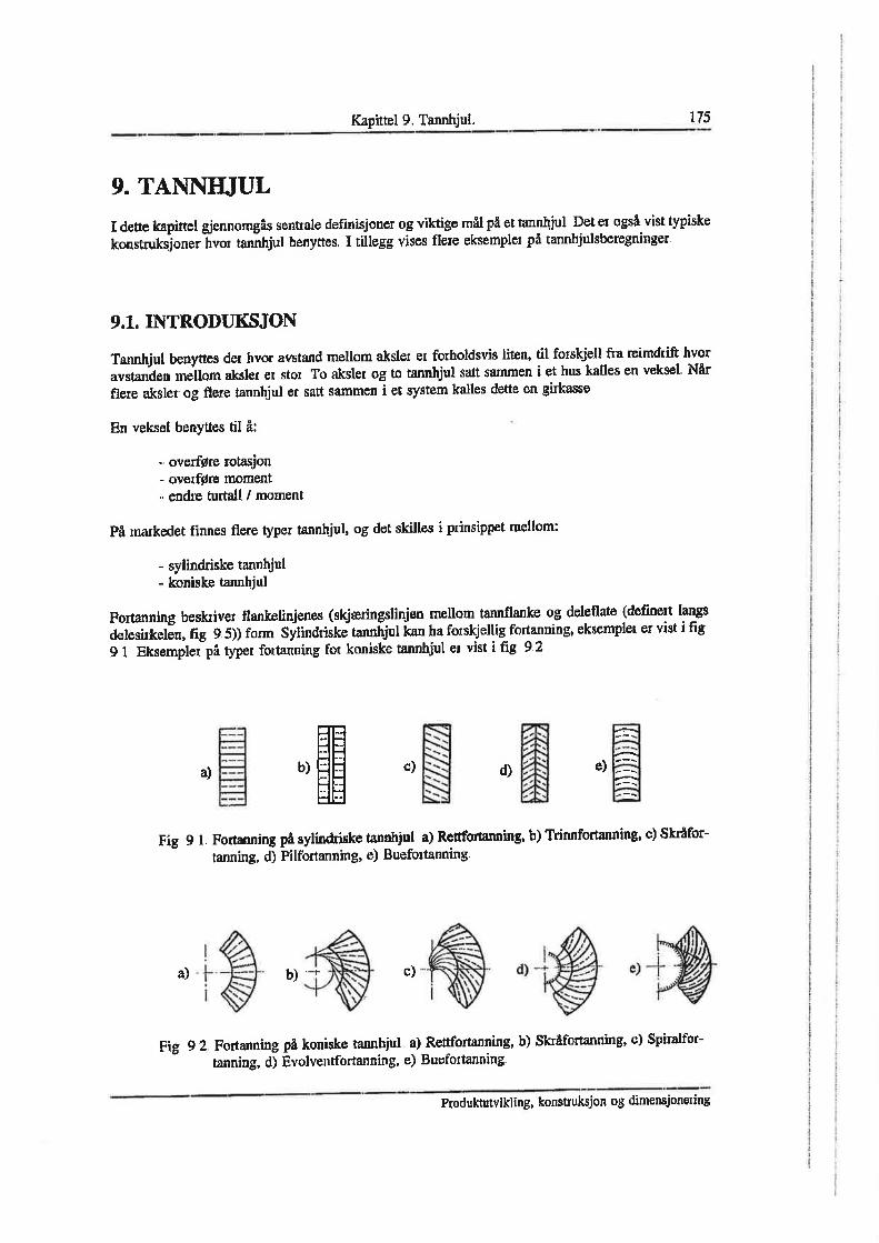


76
Appendix G
Appendix G - MASKINKONSTRUKTION II, Beregning av sylindriske
tannhjul med rette tenner


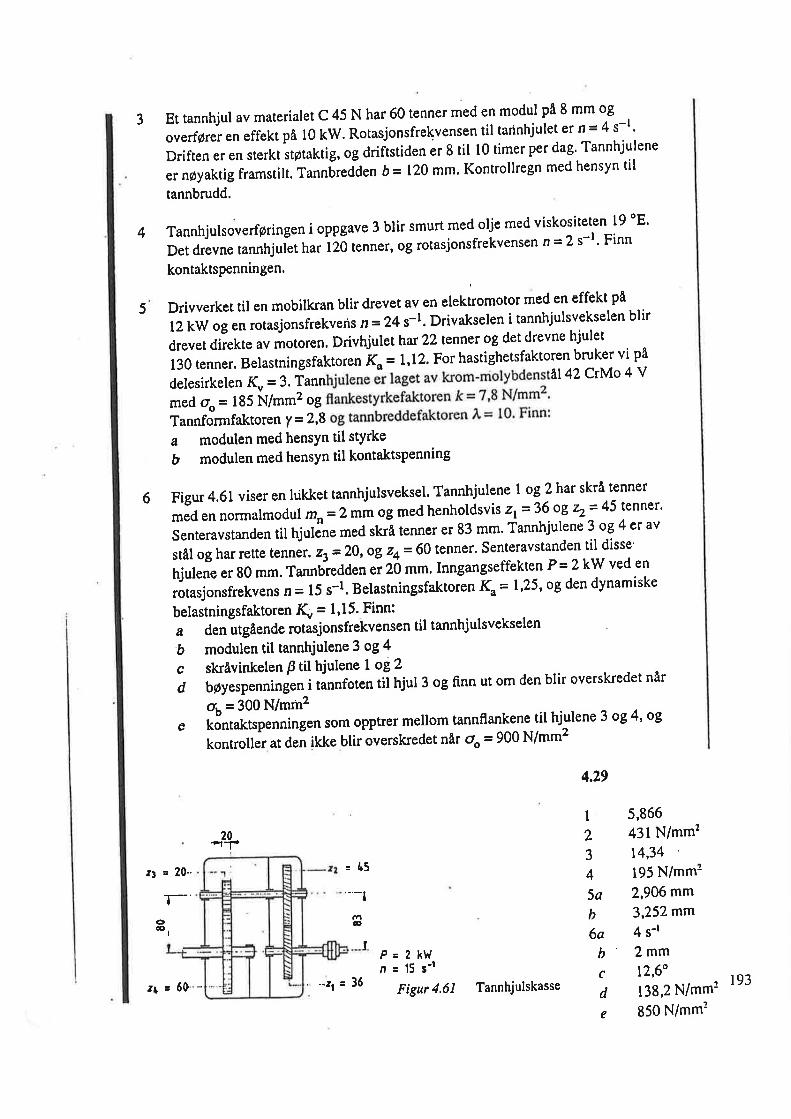


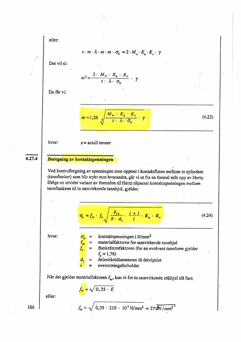

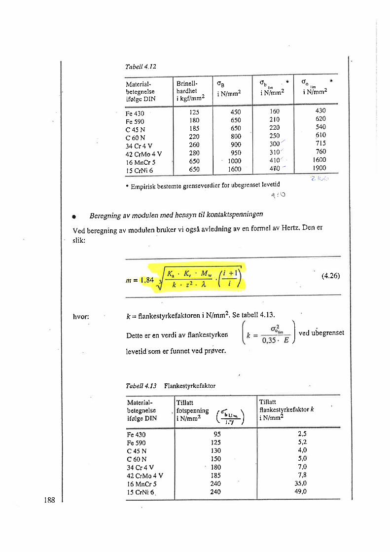

90
Appendix H
Appendix H - Rullingslager Kapittel 7


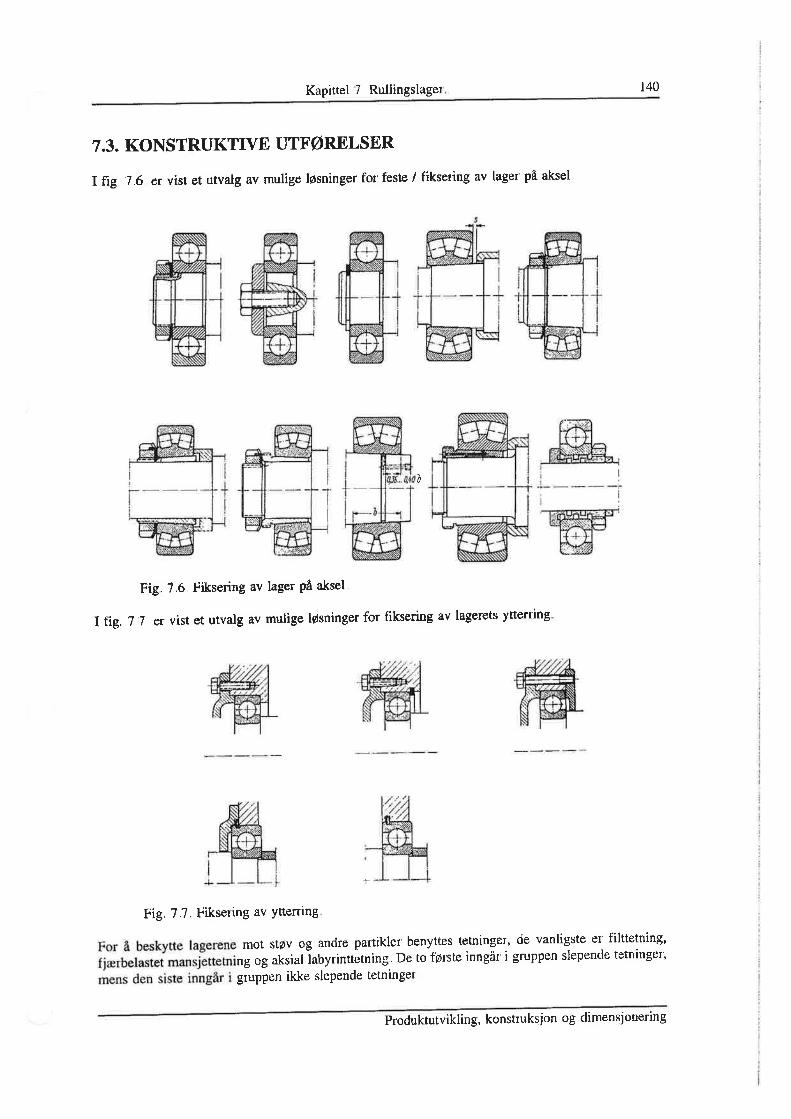


97
Appendix I
Appendix I – Sfåfiska rullager


104
Appendix J
Appendix J – Gantt Chart
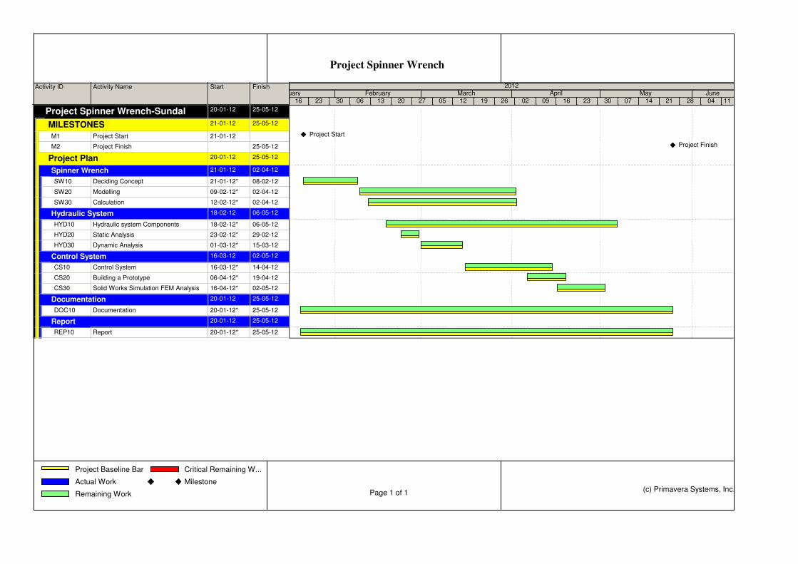
Activity ID Activity Name Start Finish
Project Spinner Wrench-SundalProject Spinner Wrench-Sundal 20-01-12 25-05-12
MILESTONESMILESTONES 21-01-12 25-05-12
M1 Project Start 21-01-12
M2 Project Finish 25-05-12
Project PlanProject Plan 20-01-12 25-05-12
Spinner WrenchSpinner Wrench 21-01-12 02-04-12
SW10 Deciding Concept 21-01-12* 08-02-12
SW20 Modelling 09-02-12* 02-04-12
SW30 Calculation 12-02-12* 02-04-12
Hydraulic SystemHydraulic System 18-02-12 06-05-12
HYD10 Hydraulic system Components 18-02-12* 06-05-12
HYD20 Static Analysis 23-02-12* 29-02-12
HYD30 Dynamic Analysis 01-03-12* 15-03-12
Control SystemControl System 16-03-12 02-05-12
CS10 Control System 16-03-12* 14-04-12
CS20 Building a Prototype 06-04-12* 19-04-12
CS30 Solid Works Simulation FEM Analysis 16-04-12* 02-05-12
DocumentationDocumentation 20-01-12 25-05-12
DOC10 Documentation 20-01-12* 25-05-12
ReportReport 20-01-12 25-05-12
REP10 Report 20-01-12* 25-05-12
16 23 30 06 13 20 27 05 12 19 26 02 09 16 23 30 07 14 21 28 04 11January February March April May June
2012
Project Start
Project Finish
Project Spinner Wrench
Project Baseline Bar
Actual Work
Remaining Work
Critical Remaining W...
Milestone
Page 1 of 1
(c) Primavera Systems, Inc.

106
Appendix K
Appendix K – DRAWING