Master Software Architecture Document · Master Software Architecture Document – Page 4 / 29...
29
Commission européenne, B-1049 Bruxelles / Europese Commissie, B-1049 Brussel - Belgium. Telephone: (32-2) 299 11 11. Commission européenne, L-2920 Luxembourg. Telephone: (352) 43 01-1. EUROPEAN COMMISSION DIRECTORATE-GENERAL INFORMATICS Information systems Directorate European Commission E-TrustEx Software Architecture Document Date: 28/03/2012 Version: 0.1 Authors: Olivier Derveau, George Vaicar Revised by: Approved by: Public: Reference Number:
Transcript of Master Software Architecture Document · Master Software Architecture Document – Page 4 / 29...

Commission européenne, B-1049 Bruxelles / Europese Commissie, B-1049 Brussel - Belgium. Telephone: (32-2) 299 11 11.
Commission européenne, L-2920 Luxembourg. Telephone: (352) 43 01-1.
EUROPEAN COMMISSION DIRECTORATE-GENERAL INFORMATICS Information systems Directorate
European Commission
E-TrustEx
Software Architecture Document
Date: 28/03/2012
Version: 0.1
Authors: Olivier Derveau, George Vaicar
Revised by:
Approved by:
Public:
Reference Number:

e-TrustEx Software Architecture Document Page i
TABLE OF CONTENTS
1. INTRODUCTION .................................................................................................................................... 4
1.1. Purpose .................................................................................................................................................... 4
1.2. Scope ....................................................................................................................................................... 4
1.3. References ............................................................................................................................................... 4
1.4. Overview.................................................................................................................................................. 4
2. ARCHITECTURAL REPRESENTATION ........................................................................................... 4
3. ARCHITECTURAL GOALS AND CONSTRAINTS ........................................................................... 5
4. SECURITY ................................................................................................................................................ 5
4.1. Security Overview ................................................................................................................................... 5
4.1.1. Introduction .......................................................................................................................................... 5
4.1.2. Transport Layer Security ...................................................................................................................... 6
4.1.3. Message Level Security ........................................................................................................................ 7
4.1.4. Application Level Security ................................................................................................................... 7
4.1.5. Logging and Auditing ........................................................................................................................... 8
4.1.6. Other ..................................................................................................................................................... 8
4.2. Philosophy ............................................................................................................................................... 8
4.3. Mapping of Features to Requirements ..................................................................................................... 8
4.3.1. Mapping ................................................................................................................................................ 8
4.3.2. Database Security ................................................................................................................................. 9
5. USE-CASE VIEW................................................................................................................................... 10
5.1.1. Selection Rationale ............................................................................................................................. 10
5.1.2. Diagram .............................................................................................................................................. 11
6. LOGICAL VIEW ................................................................................................................................... 13
6.1.1. Overview............................................................................................................................................. 13
6.1.2. Architecturally Significant Design Packages ...................................................................................... 13
6.1.3. Use-Case Realizations ........................................................................................................................ 15
6.1.3.1. A sender system stores a document wrapper ............................................................................... 15
6.1.3.2. A sender system submits a document bundle ................................................................................... 17
6.1.3.3. A receiver system retrieves a document bundle ............................................................................... 19
6.1.3.4. A receiver system retrieves a document wrapper ............................................................................. 19
7. DEPLOYMENT VIEW .......................................................................................................................... 20
8. IMPLEMENTATION VIEW ................................................................................................................ 21
8.1. Overview................................................................................................................................................ 21
8.2. Layers .................................................................................................................................................... 22
8.2.1. Service Bus Layer ............................................................................................................................... 22
8.2.2. Asynchronous Business Layer ............................................................................................................ 23

e-TrustEx Software Architecture Document Page 2
8.2.3. Data Access Layer .............................................................................................................................. 23
9. DATA VIEW ........................................................................................................................................... 23
9.1. Data Model ............................................................................................................................................ 23
9.2. State Machines ....................................................................................................................................... 25
9.2.1. Introduction ........................................................................................................................................ 25
9.2.2. Legend ................................................................................................................................................ 26
9.2.3. Generic State Machines ...................................................................................................................... 26
9.2.3.1. Generic State Machine for an Incoming Object ............................................................................... 26
9.2.3.2. Generic State Machine for an Outgoing Object ............................................................................... 26
9.2.3.3. Specific State Machines for Bundle ................................................................................................. 27
10. SIZE AND PERFORMANCE ............................................................................................................. 27
11. QUALITY .............................................................................................................................................. 27
11.1. Extensibility ......................................................................................................................................... 27
11.2. Reliability ............................................................................................................................................ 27
11.3. Portability ............................................................................................................................................ 28
e-TrustEx Software Architecture Document Page iii
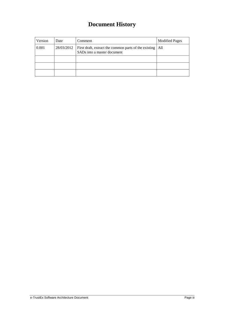
Document History
Version Date Comment Modified Pages
0.001 28/03/2012 First draft, extract the common parts of the existing
SADs into a master document
All
Master Software Architecture Document – Page 4 / 29 Document Version 0.4 dated 20/04/2012
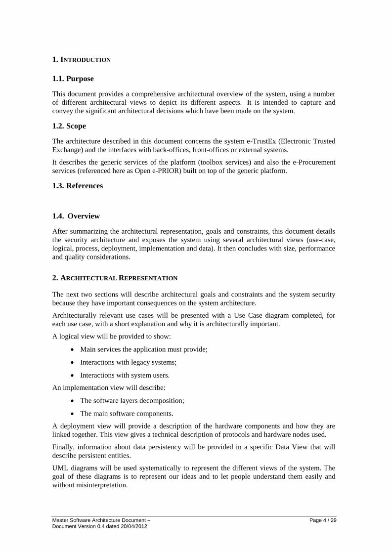
1. INTRODUCTION
1.1. Purpose
This document provides a comprehensive architectural overview of the system, using a number
of different architectural views to depict its different aspects. It is intended to capture and
convey the significant architectural decisions which have been made on the system.
1.2. Scope
The architecture described in this document concerns the system e-TrustEx (Electronic Trusted
Exchange) and the interfaces with back-offices, front-offices or external systems.
It describes the generic services of the platform (toolbox services) and also the e-Procurement
services (referenced here as Open e-PRIOR) built on top of the generic platform.
1.3. References
1.4. Overview
After summarizing the architectural representation, goals and constraints, this document details
the security architecture and exposes the system using several architectural views (use-case,
logical, process, deployment, implementation and data). It then concludes with size, performance
and quality considerations.
2. ARCHITECTURAL REPRESENTATION
The next two sections will describe architectural goals and constraints and the system security
because they have important consequences on the system architecture.
Architecturally relevant use cases will be presented with a Use Case diagram completed, for
each use case, with a short explanation and why it is architecturally important.
A logical view will be provided to show:
Main services the application must provide;
Interactions with legacy systems;
Interactions with system users.
An implementation view will describe:
The software layers decomposition;
The main software components.
A deployment view will provide a description of the hardware components and how they are
linked together. This view gives a technical description of protocols and hardware nodes used.
Finally, information about data persistency will be provided in a specific Data View that will
describe persistent entities.
UML diagrams will be used systematically to represent the different views of the system. The
goal of these diagrams is to represent our ideas and to let people understand them easily and
without misinterpretation.
Master Software Architecture Document – Page 5 / 29 Document Version 0.4 dated 20/04/2012
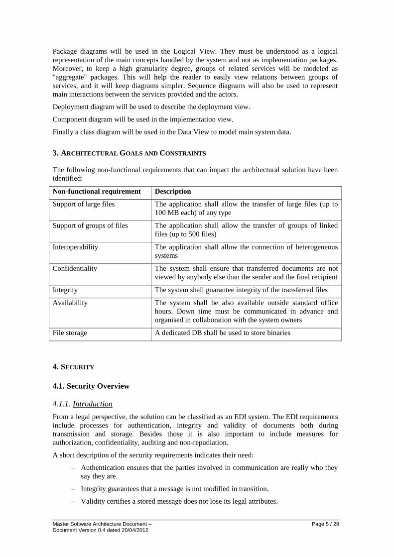
Package diagrams will be used in the Logical View. They must be understood as a logical
representation of the main concepts handled by the system and not as implementation packages.
Moreover, to keep a high granularity degree, groups of related services will be modeled as
"aggregate" packages. This will help the reader to easily view relations between groups of
services, and it will keep diagrams simpler. Sequence diagrams will also be used to represent
main interactions between the services provided and the actors.
Deployment diagram will be used to describe the deployment view.
Component diagram will be used in the implementation view.
Finally a class diagram will be used in the Data View to model main system data.
3. ARCHITECTURAL GOALS AND CONSTRAINTS
The following non-functional requirements that can impact the architectural solution have been
identified:
Non-functional requirement Description
Support of large files The application shall allow the transfer of large files (up to
100 MB each) of any type
Support of groups of files The application shall allow the transfer of groups of linked
files (up to 500 files)
Interoperability The application shall allow the connection of heterogeneous
systems
Confidentiality The system shall ensure that transferred documents are not
viewed by anybody else than the sender and the final recipient
Integrity The system shall guarantee integrity of the transferred files
Availability The system shall be also available outside standard office
hours. Down time must be communicated in advance and
organised in collaboration with the system owners
File storage A dedicated DB shall be used to store binaries
4. SECURITY
4.1. Security Overview
4.1.1. Introduction
From a legal perspective, the solution can be classified as an EDI system. The EDI requirements
include processes for authentication, integrity and validity of documents both during
transmission and storage. Besides those it is also important to include measures for
authorization, confidentiality, auditing and non-repudiation.
A short description of the security requirements indicates their need:
– Authentication ensures that the parties involved in communication are really who they
say they are.
– Integrity guarantees that a message is not modified in transition.
– Validity certifies a stored message does not lose its legal attributes.
Master Software Architecture Document – Page 6 / 29 Document Version 0.4 dated 20/04/2012
– Authorization ensures that users only have access to the resources they are granted to.
– Confidentiality is needed to prevent third parties from eavesdropping on information
that is being transmitted.
– Auditing controls enable relevant parties like authorized bodies to inspect transactions
afterwards.
– Non-repudiation measures prevent users from denying actions they have undertaken.
Besides technical security measures, there will also be a focus on other aspects that have a
positive impact on security. These other aspects comprise procedures and logging. The use of
adequate business procedures can guarantee a high level of security without having technical
measures that are too strict to be workable in a day to day environment. An appropriate level of
logging and audit trails will provide involved parties a timely indication of possible issues and a
starting point for debugging or investigations.
Finally, in addition to operational needs for security, care will also be taken to extend security
measures from the system to the archiving of business documents. Legal constraints impose extra
requirements to guarantee that archived documents remain unmodified and readable throughout
their storage period which can last more than ten years.
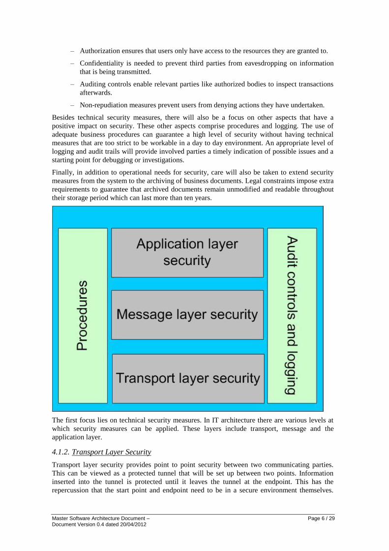
The first focus lies on technical security measures. In IT architecture there are various levels at
which security measures can be applied. These layers include transport, message and the
application layer.
4.1.2. Transport Layer Security
Transport layer security provides point to point security between two communicating parties.
This can be viewed as a protected tunnel that will be set up between two points. Information
inserted into the tunnel is protected until it leaves the tunnel at the endpoint. This has the
repercussion that the start point and endpoint need to be in a secure environment themselves.

Master Software Architecture Document – Page 7 / 29 Document Version 0.4 dated 20/04/2012
Otherwise your data could be compromised when it leaves the tunnel. At the transport level we
foresee to be using HTTPS.
HTTPS is a secure version of the HTTP protocol and is being used to protect data transactions
for commercial and financial purposes. It uses a Secure Socket Layer (SSL) and digital
certificates to encrypt a data transfer session over an otherwise insecure HTTP connection. SSL
transactions are negotiated by means of a key-based encryption algorithm between the client and
the server. A digital certificate is being sent by the server to the client to prove its identity. To
verify the certificate, the client must possess the root certificate for the key that was used to sign
the server's certificate. This can be enabled by either exchanging and installing the root
certificate in front or using a root authority that is trusted between both parties. Note that
normally HTTPS only guarantees the identity of the server and that the client does not need to
identify itself to setup a communication channel. To overcome this problem and to meet the
requirement of non-repudiation, mutual authentication is needed by using either client
certificates or a security token. We will discuss both client certificates and tokens and list the
impacts of using either one of them. Firstly there are client certificates which, just like server
certificates can verify the identity of the client and which can be used to set up a secure
communication channel or to digitally sign messages. The drawback however is that the use of
client certificates is rather complex and requires every supplier to obtain and manage its own
certificates and the setup of a PKI (Public Key Infrastructure) to provide a repository of digital
identities. Secondly there are security tokens which can be used to alleviate the complexity of
client certificates. Security tokens can exist in many forms from one time passwords (OTP's)
generated by a hardware device to normal passwords which we are used to enter on websites
every day. Our assumption is that normal passwords are the best balance between security and
simplicity. Given the fact that we are already applying HTTPS to set up the initial secure
connection, using HTTP basic authentication with normal passwords over this secure connection
gives us enough confidentiality that passwords are not stolen. Our assumption however does not
hold if cautious care has to be taken to prevent password stealing by keylogging or phishing
techniques.
The transport level measures on itself will provide restricted access to the system, confidentiality
and integrity of message exchange. Authenticity of origin and integrity of received and stored
content can be assured in combination with auditing and logging features that will be described
below.
4.1.3. Message Level Security
The next level of security protects the message exchange and the data itself instead of the
transportation channel. In fact, message level security could completely replace transport level
security, but this is not really practical for the intended architecture and its inherent limitations.
To cater for the need for non-repudiation, we will rely on a SOAP interceptor in combination
with the secure transport channel discussed above. The SOAP interceptor has the ability to
digest, monitor and log the messages that are exchanged between the users and the system. In
more detail, this means that before entering the system and while still being in a secure channel
the exchanged messages will be logged to a secure storage. As a result, the system is able to
prove or disprove having previously sent or received data for a particular user.
4.1.4. Application Level Security
The highest level in the protocol stack is the application level. Application level security
manages access to the services the system provides. To achieve a controllable method of
handling access, user profiles will be used. A user profile is a set of user attributes that can be
combined with access rights to facilitate management of system resource utilisation. Data-
ownership is managed by only giving users access to the data they have created or to the data
they have sufficient rights to.
Master Software Architecture Document – Page 8 / 29 Document Version 0.4 dated 20/04/2012
4.1.5. Logging and Auditing
Logging and auditing will be used as a complementary feature besides the technical security
measures described above. It is foreseen that logging and auditing will occur at various levels in
the system.
Firstly, all exchanged information, incoming as well as outgoing messages, between the system
and the users of the system will be intercepted and logged to a database. This will be done by a
SOAP interceptor. Besides the exchanged information all logons, transactions, checks and other
actions as well as all actions performed by system administrators will be logged by either the
process manager or an add-on to the ESB. The level of logging will not only provide guarantees
to the sending and reception of messages to support the feature of non-repudiation, but will also
help technicians and architects resolve technical errors in case of system malfunction.
Secondly, all actions that result in accessing the system or modifying the state or functionality of
the system are logged. This not only includes authentication and authorization of users, but also
the actions that administrators undertake to maintain or update the system. It should never be
possible that one person, no matter what level of access he has, can modify parts of the system
without leaving an audit trail.
All gathered logs will be maintained in a database that has restricted access and will be backed
up regularly. It is assumed that the logs cannot be tampered with in order to support their non-
repudiation characteristics.
4.1.6. Other
It is assumed that the employed security measures guarantee a maximum and agreed level of
security while incurring minimal effort for the users of the system. The solution should be well
protected but workable.
In order to provide a flexible and reliable solution that can be used across borders and without
restrictions, the goal is to have a 24/7 uptime of the system. Only small and limited downtimes
for updating the system are allowed and should be kept to a minimum.
An important security related aspect of the system is legal data protection and privacy. The
system must ensure that all data exchanged between the system and its users are protected from
disclosure to any unauthorized party. Additionally, it is mandatory that all gathered information
about the users of the system is treated in harmony with existing European privacy protection
regulations.
4.2. Philosophy
The overall philosophy of protection that will be used in the platform is to provide a manageable
and working solution that will be used in a day to day environment while keeping an adequate
level of security. This level of security will cover all legal and regulatory aspects imposed by
various stakeholders and will be thorough enough to prevent abuse of the system. Care will be
taken however that the solution will not turn into an unworkable system filled with extensive
security measures just for the purpose of adding technical specifications. It is assumed that a
good level of technical security, together with well-designed procedures, audit controls and
logging provide the best balance between cost and benefits.
4.3. Mapping of Features to Requirements
4.3.1. Mapping
The following table lists the security requirements together with the features which implement
them.

Master Software Architecture Document – Page 9 / 29 Document Version 0.4 dated 20/04/2012
Requirement Feature
Access to the system HTTPS with basic HTTP username and password authentication
will be used.
Confidentiality of message
exchange
HTTPS provides a secure transport channel and prevents
untrusted third parties from reading exchanged messages.
Exchanged data integrity HTTPS provides a secure transport channel and prevents
untrusted third parties from tampering with exchanged data
during transport.
Authenticity of origin and
integrity of content
Authentication with username and password, together with a
secure transport channel, logging of exchanged data and secure
database storage provides security about the origin and integrity
of the content.
Non-repudiation Non-repudiation is guaranteed by the SOAP interceptor which
monitors and logs all exchanged traffic in cooperation with a
secure transport channel where users are authenticated over
HTTPS.
Access to services and user
profiles
User profiles will be used that can be combined with access
rights to facilitate management of system resource utilisation.
Data ownership Data ownership is assured by only giving users access to the
data they have created or have sufficient rights to read or
modify.
Archiving security A secured database with restricted access and regular protected
backups will provide archiving security.
Logging actions and
messages
This requirement will be covered by a SOAP interceptor to
intercept all exchanged messages in the system.
Access to logs and logging
modification
Logs will be stored in a secure database with restricted access
and regular protected backups.
Max level of transparency,
minimum effort and agreed
level of security
The architectural design covers a balance between usability and
protection of the system without compromising any security
aspects.
Legal data protection and
privacy
All exchanged data between the system and its users are
protected and personal data about users of the system is stored
securely where unauthorized users or untrusted parties do not
have access to.
All database connections and disconnections are audited (real
username, terminal, logon time, logoff time.
4.3.2. Database Security
The databases that will contain business data, logging information and audit trails will be kept in
a secure environment where only authorized users have access to. Audit trails are kept to ensure
that the data is not tampered with. Additionally, it is assumed that regular backups of the
databases are generated and securely archived.
The exact database security measures depend on the specific infrastructure where the system is
deployed.

Master Software Architecture Document – Page 10 / 29 Document Version 0.4 dated 20/04/2012
The security features that should be considered are listed below: strong user authentication, data
integrity, data encryption, auditing, data source protection (security policy on Application
Server), backup and restore.
5. USE-CASE VIEW
This section provides a representation of the architecturally significant use cases.
5.1.1. Selection Rationale
The architecturally significant use cases have been selected based on the following criteria:
– Use cases affecting multiple components of the system, thereby providing a cross-cutting
view of the system architecture;
– Use cases representing critical parts of the architecture, thereby addressing the technical
risks of the project at an earlier stage.
The following use cases have been selected.
Use case addressing the submission of documents by external applications (UC Submit
Document Bundle)
Use case addressing the submission of ( potentially large) binary files (UC Store
Document Wrapper)
Use case addressing the retrieval of ( potentially large) binary files (UC Retrieve
Document Wrapper Request)
A use case addressing the retrieval of documents by external applications (UC Submit
Retrieve Request)

Master Software Architecture Document – Page 11 / 29 Document Version 0.4 dated 20/04/2012
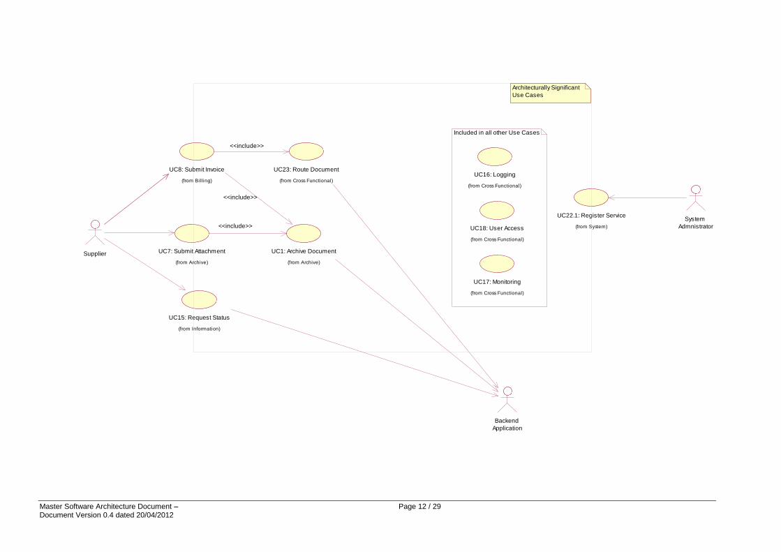
5.1.2. Diagram
The following Use Cases diagram displays the e-TrustEx use cases chosen as architecturally relevant and their links with external applications (here the Sender and
Receiver Systems).
For the eProcurement module, the Supplier in the below use case diagram can play the role of both Sender and Receiver depending on the use case.
Master Software Architecture Document – Page 12 / 29 Document Version 0.4 dated 20/04/2012
UC18: User Access
(from Cross Functional)
UC22.1: Register Service
(from System)
System
Admnistrator
UC23: Route Document
(from Cross Functional)
UC1: Archive Document
(from Archive)
Backend
Application
UC8: Submit Invoice
(from Bi lling)
<<include>>
<<include>>
UC15: Request Status
(from Information)
Supplier UC7: Submit Attachment
(from Archive)
<<include>>
UC17: Monitoring
(from Cross Functional)
UC16: Logging
(from Cross Functional)
Included in all other Use Cases
Architecturally Significant
Use Cases

Master Software Architecture Document – Page 13 / 29 Document Version 0.4 dated 20/04/2012
6. LOGICAL VIEW
6.1.1. Overview
In this chapter we describe the main application packages, how they interact and how they
implement system use cases.
In the subsection 6.1.2 we describe the main packages of the system and how they are called
by the external applications.
In the subsection 6.1.3 we explain how these packages participate to the implementation of
the architecturally relevant use cases. Sequence diagrams are provided to illustrate packages
interactions.
6.1.2. Architecturally Significant Design Packages
The following diagram provides a high level view of the main packages composing the
system. This diagram also shows the external systems (represented as blue packages).
It is important to understand that even if just two external systems are shown on the diagram
there could be several external systems. The interfaces provided by e-TrustEx will remain
identical and the fact that other systems use them have no impact on the software (low
coupling is implemented) but only on the infrastructure capacity to support the load.
Sender and Receiver systems access to e-TrustEx via a Service Bus that publishes the
available services. It calls different generic packages responsible for SLA management,
monitoring, user access and logging.
The Binary File Service is a Web Service deployed outside the Service Bus because this one
does not allow enforcing maximum file size limitation and various SLA rules. It uses the
Binary File Management services.
Moreover the services are implemented by the packages Inbox, Retrieve, Bundle
Management, and Binary File Management.
These services use lower level packages to route and validate messages, to store or search
messages in the e-TrustEx database.

Master Software Architecture Document – Page 14 / 29 Document Version 0.4 dated 20/04/2012
The following diagram depicts another view on the system in the context of the eProcurement module.
Master Software Architecture Document – Page 15 / 29 Document Version 0.4 dated 20/04/2012
6.1.3. Use-Case Realizations
The following use cases have been chosen to describe how software packages behave:
A sender system stores a document wrapper (binary file)
A sender system submits a document bundle
A receiver system retrieves a document bundle
A receiver system retrieves a document wrapper(binary file)
Indeed these use cases use all the main packages of the architecture.
6.1.3.1. A sender system stores a document wrapper
The following diagram shows the different interactions occurring during the “Store
Document Wrapper” use case.
The Sender System submits a binary file (and its descriptor as an XML file) via a web service
published outside the Service Bus and named Binary File Service. This one logs the access,
authenticates and authorizes the system user, verify SLA rules and update the monitoring
information.
The Binary File Service delegates the call to the BinaryFileManagement package that stores
the binary file in the e-TrustEx database. HTTP chunking is used for the file transfer and the
binary file is stored chunk by chunk. That avoids loading the full file in the Application
Server memory. A check on the file size is also done by that package in order to close the
HTTP connection whenever the maximum file size is reached. That prevents the system from
Deny Of Services attacks where the sender would send huge files, blocking the HTTP threads
for a very long period. The file size check also prevents such attacks that would fulfil the File
System (table space) and so lead to a server crash.
The BinaryFileManagement package processes synchronously the file descriptor. It validates
and persists it in the e-TrustEx database (in the schema dedicated to the storage of large
binary files).

Master Software Architecture Document – Page 16 / 29 Document Version 0.4 dated 20/04/2012
Master Software Architecture Document – Page 17 / 29 Document Version 0.4 dated 20/04/2012
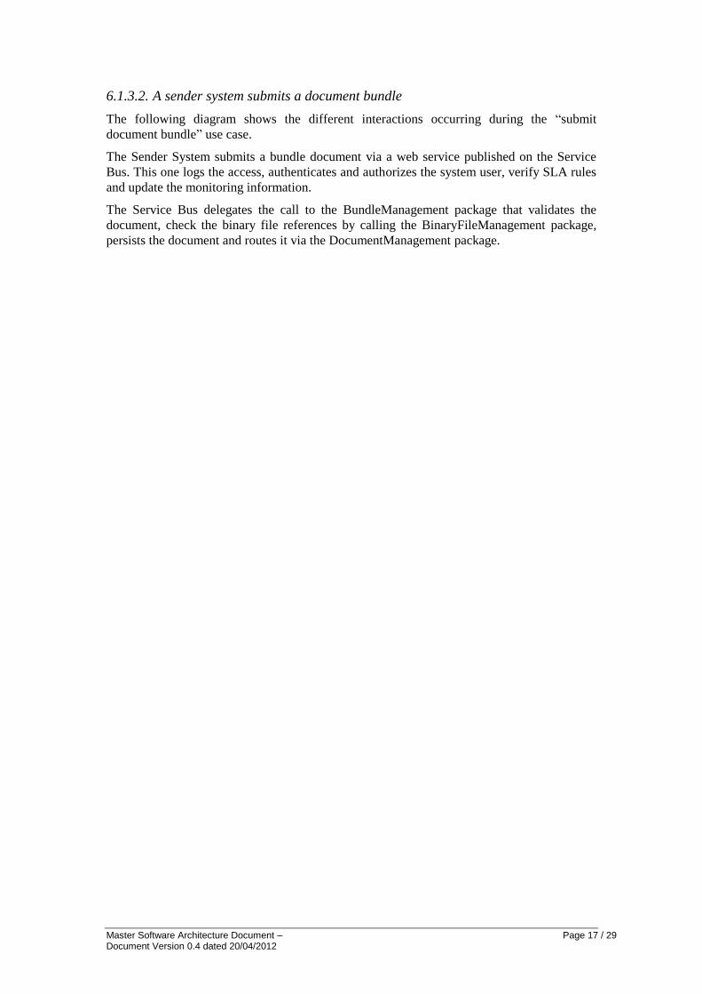
6.1.3.2. A sender system submits a document bundle
The following diagram shows the different interactions occurring during the “submit
document bundle” use case.
The Sender System submits a bundle document via a web service published on the Service
Bus. This one logs the access, authenticates and authorizes the system user, verify SLA rules
and update the monitoring information.
The Service Bus delegates the call to the BundleManagement package that validates the
document, check the binary file references by calling the BinaryFileManagement package,
persists the document and routes it via the DocumentManagement package.
Master Software Architecture Document – Page 18 / 29 Document Version 0.4 dated 20/04/2012

Master Software Architecture Document – Page 19 / 29 Document Version 0.4 dated 20/04/2012
6.1.3.3. A receiver system retrieves a document bundle
The following diagram shows the different interactions occurring during the “retrieve
document bundle” use case.
The Receiver System retrieves a document bundle via a web service published on the Service
Bus. This one logs the access, authenticates and authorizes the system user, verify SLA rules
and update the monitoring information.
The Service Bus delegates the call to the Retrieve package that uses the
DocumentManagement package that is responsible of the validation of the retrieve request
and the retrieval of the document.
The retrieve document service is generic and so can be used for different kinds of documents.
The retrieval of a document bundle is possible by specifying its identifier and its type.
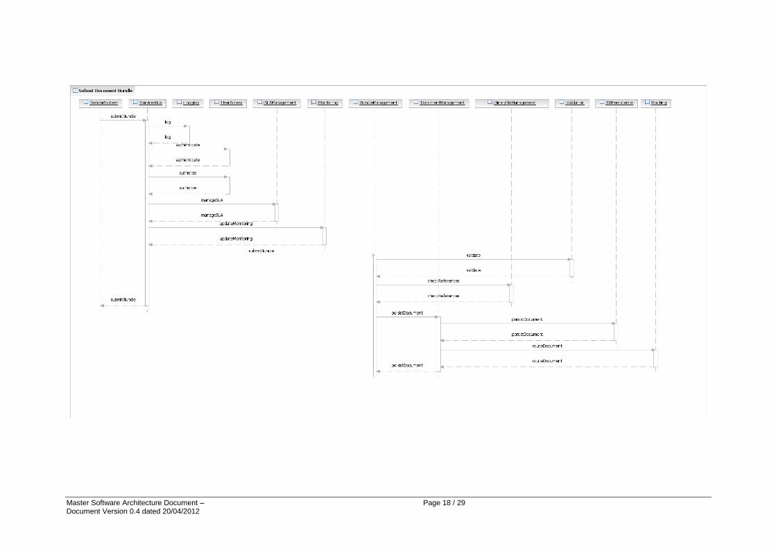
6.1.3.4. A receiver system retrieves a document wrapper
The following diagram shows the different interactions occurring during the retrieve
document wrapper use case.
Master Software Architecture Document – Page 20 / 29 Document Version 0.4 dated 20/04/2012
The Receiver System retrieves a binary file (and its descriptor as an XML Document
Wrapper) via a web service published outside the Service Bus. This one logs the access,
authenticates and authorizes the system user, verify SLA rules and update the monitoring
information.
The Service Bus delegates the call to the BinaryFileManagement package that validates the
request, retrieves the file descriptor and the binary file itself in the e-TrustEx database (in the
schema dedicated to the storage of large binary files). That package also checks if the
receiver has access to the file (meaning that it is linked to a bundle document that it has
received).
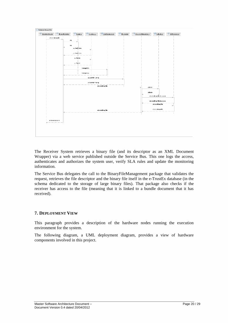
7. DEPLOYMENT VIEW
This paragraph provides a description of the hardware nodes running the execution
environment for the system.
The following diagram, a UML deployment diagram, provides a view of hardware
components involved in this project.
Master Software Architecture Document – Page 21 / 29 Document Version 0.4 dated 20/04/2012
Figure 1: System Hardware Components
It is important to note that not all physical nodes are represented on this diagram. Indeed
Database Servers and Application Servers could be duplicated for scalability and availability
reasons. Moreover, security equipment like firewalls is not shown.
The following are the identified hardware nodes.
Front-end side:
Supplier Client Application: Supplier client application of Open e-PRIOR;
Supplier Access point: the PEPPOL network access point used by the Supplier to
submit documents. (for more information on PEPPOL please check the website:
http://www.peppol.eu)
Business side:
System Application Server: The whole e-PRIOR System can run on a JBoss
Application Server but clustering is possible.
System Database Servers: the system's persistent data will be recorded in relational
databases. The current version of Open e-PRIOR uses HSQL DB embedded in JBoss.
Back-Office side:
Back-Office Servers: These are the Customer's Back Office Application Servers.
8. IMPLEMENTATION VIEW
8.1. Overview
The following schema describes software layers of the system and their components. The
next paragraphs will describe each element.
The Sender and Receiver systems access the system via Web Services published on the
Service Bus and BinaryFile Service components.
They delegate the calls to Synchronous Services. If the requested service is “submit
document bundle”, a limited validation is realized via the validation component and the
Asynchronous Services component is called (asynchronously). This one does the validation
(validation component), the routing (routing component) and persists the document in the
application’s database (DB Persistence component).
The other services are synchronous and so are directly implemented by the Synchronous
Services component that does some validation and performs the business logic. It also uses
the DB Persistence component to access the database.

Master Software Architecture Document – Page 22 / 29 Document Version 0.4 dated 20/04/2012
8.2. Layers
8.2.1. Service Bus Layer
This component represents the Web Services published on the Enterprise Service
Bus. They interact with the Synchronous services for read services and
asynchronous services for write services;
BinaryFile Service component: this component represents the Web Service
responsible for storing and retrieving Document Wrapper (binary files). It interacts
with the Synchronous Services component.
Synchronous services component: this component represents the business logic for
the synchronous services. It uses Validation component to validate the different
incoming requests and it uses the DB persistence component to access the
database. It also performs limited validation and delegate the “submit document
bundle” calls to the asynchronous services component;
Validation component: this component is responsible for the incoming request
validation.
Master Software Architecture Document – Page 23 / 29 Document Version 0.4 dated 20/04/2012
8.2.2. Asynchronous Business Layer
Asynchronous services component: this component represents the write services
business logic. It uses the validation, routing and DB persistence components to
validate, route and store the documents;
Validation component: this component is responsible for the incoming document
validation;
Routing component: this component is responsible for the routing of messages to
the right receiver. It also uses the DB persistence component to retrieve routing
information.
8.2.3. Data Access Layer
This layer is running on both Service Bus Layer and the Asynchronous Business Layer for
the DB persistence component. It is in fact a logical layer deployed on two separated servers.
DB Persistence component: this component is responsible for database information
retrieval or storage. It is used to retrieve document bundle, store them, to find
routing information, to store and retrieve document wrapper (binary files). That
component uses two distinct schemas: one to store the business documents (please
see the diagram in chapter 9.1) and the second is only used to store large binaries;
9. DATA VIEW
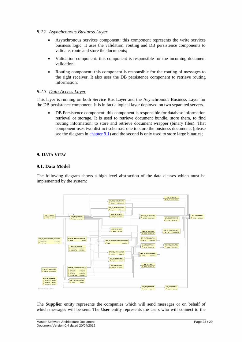
9.1. Data Model
The following diagram shows a high level abstraction of the data classes which must be
implemented by the system:
The Supplier entity represents the companies which will send messages or on behalf of
which messages will be sent. The User entity represents the users who will connect to the

Master Software Architecture Document – Page 24 / 29 Document Version 0.4 dated 20/04/2012
system to send the messages. If a Supplier works directly with the system, a User entry will
also be needed for it. If a Supplier uses a third-party to send documents (a factoring company
for the invoices, for example), then it will be linked to the User entry which identifies the
third-party. The third-party itself will not need a Supplier entry. The link between a Supplier
and a User is implemented by the SupplierAgreement entity. A Supplier can be linked to
more than one User, for example a factoring company for its invoices and its own User for
other documents.
The BackEnd entity represents an application implementing a Functionality for an Internal
Department. Its userName is the system user name which the back-end will use to call the
services.
The Functionality entity represents the possible functionalities of a BackEnd: invoicing,
ordering, archiving, requesting… An InternalDepartment should have one BackEnd per
Functionality. A SupplierAgreement and an InternalDepartment sign an
InterchangeAgreement, whereby they agree to exchange documents according to a given
Profile.
The Profile entity is inspired by the NES profiles (e.g.: Basic Invoice, Invoice with Dispute,
Procurement Cycle). A Profile is linked to an InterchangeAgreement.
The ObjectType entity represents all the types of objects supported by the system (Initial
Request, Offer or Extension Request, Order, Invoice, Dispute, Credit Note, Attachment,
Error, etc). The Object entity represents a specific object of a given type, which will be
handled via the sending of Messages. Optionally, it can reference a message from another
object (eg. an Initial Request object can reference another Initial Request object in the case of
a cascade, an Invoice object can reference an Signed Order message from an Order object, a
Credit Note object can reference an Invoice message from an Invoice object…) or even a
specific message in another object (eg. an Attachment can reference any message of any
object…).
An ObjectType also relates to one and only one Functionality (for ex. the object types
"Invoice", "Dispute" and "Credit Note" belong to the "invoicing" functionality, the object
types "Initial Request" and "Extension Request" belong to the "request" functionality…).
The Support entity indicates which ObjectTypes are supported by a given Profile. For
example, the 'Invoice with Dispute' Profile supports the Invoice, Dispute, Credit Note and
Attachment object types.
The Message entity represents the messages which will transit through e-PRIOR. The
inOutFl indicates whether it is an inbound message (from a Supplier system) or an outbound
message (from a back-end). If it is an inbound message, then the sender is identified by a
SupplierAgreement id. For an outbound message, the destination is identified by the Supplier
id. In other words, a message can be sent by a User on behalf of the Supplier, but a reply will
always be sent to the Supplier. The Message entity makes up the storage of the messages
which will be subject to registration, filing and archiving. It contains a rawContents attribute
which will receive the payload of the XML, and a canonicalContents attribute which will
receive, when applicable, the canonical version of the XML. It also contains a
humanReadableContents attribute, which will contain the result of the transfomartion of the
XML to a format readable by a user.
A Message can reference another Message (via the messageId), even a Message from another
Object.
Its phraseId will point to a phrase which will serve as title for the message. Its binaryId will
point, if applicable, to binary which was removed from the message for size reason. Its
documentId will be the id found inside the payload.
Master Software Architecture Document – Page 25 / 29 Document Version 0.4 dated 20/04/2012
The Binary entity will receive the binary data which can be inside a message. To avoid size
problems, the binary data is removed from the message and placed here. The message then
just contains a pointer to the Binary element.
A Message will have a type, implemented by the MessageType entity. Examples of message
types are Invoice, Dispute, Credit Note, Signed Order, Offer…A MessageType is linked to an
ObjectType. For example, the Dispute and Credit Note message types belong to the Dispute
object type; the Order, Order Confirmation and Signed Order message types belong to the
Order object type. A MessageType will also have a state, which corresponds to the state in
which the related object will be when such a message is sent for the object. The states are
implemented by the State entity. For example, the state of the MessageType "Credit Note"
will be "Credit Note Received". This means that when a Credit Note is received for a specific
Dispute object, the Dispute object will receive the state "Credit Note Received". The State
Machines below illustrate the different states of the different objects (as well as the links
between objects and attachments).
The Event entity records every event occurring in the system. When the event concerns a
Message, it holds a pointer to the Message. It implements the log file. The Event Level
provides a list of levels for the events: debug, info, warning, error. The developers will
associate an event level to each action performed by the system. If the level is at least the
current level of the system, then the action will be recorded as an event. The current level is
determined by the LogLevel entity, which associates an event level to a specific context: a
specific InterchangeAgreeement using a specific EndPoint.
The Service entity implements the services of the system. An EndPoint is a specific version
of a service. It corresponds to a WSDL.
The Statement entity contains sentences, error messages or any string used for the
communication between the system and a Supplier.
The Phrase and Translation entities are linked to all entities containing an attribute whose
value can be displayed on screen, and so contributes to the multilingual functionality,
together with the Language entity.
9.2. State Machines
9.2.1. Introduction
Each object of the system (including the Bundles) will have its own state machine. A state
machine is always initiated by a Sender. It starts with a specific message (e.g. "The Sender
sends a Bundle").
Only a message will be capable of passing an object from a state to the next one. A state
machine will never represent the workflow of the object in the receiver back-office. While
the object is in the receiver application, the state of the object remains the same in e-TrustEx,
until the back-office notifies (via an outbound message) that the workflow is complete.
The following sections illustrate the state machines which have to be supported by e-TrustEx.
Note:
Once a state machine instance is started, each state transition is performed by the
transmission of a message. Each message is subject to logging and monitoring.
Master Software Architecture Document – Page 26 / 29 Document Version 0.4 dated 20/04/2012
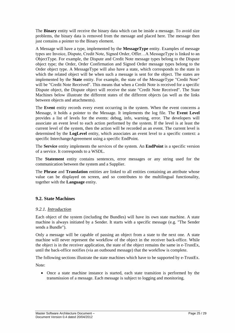
9.2.2. Legend
Intermediary State
Entry
point
Outgoing Message
Incoming Message
Final State
9.2.3. Generic State Machines
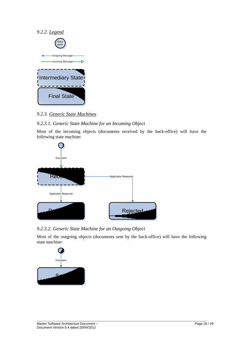
9.2.3.1. Generic State Machine for an Incoming Object
Most of the incoming objects (documents received by the back-office) will have the
following state machine:
Received
Processed Rejected
Application Response
Application Response
Document
9.2.3.2. Generic State Machine for an Outgoing Object
Most of the outgoing objects (documents sent by the back-office) will have the following
state machine:
Sent
Document
Master Software Architecture Document – Page 27 / 29 Document Version 0.4 dated 20/04/2012
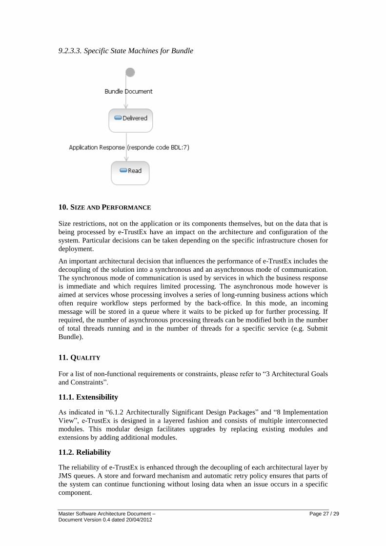
9.2.3.3. Specific State Machines for Bundle
10. SIZE AND PERFORMANCE
Size restrictions, not on the application or its components themselves, but on the data that is
being processed by e-TrustEx have an impact on the architecture and configuration of the
system. Particular decisions can be taken depending on the specific infrastructure chosen for
deployment.
An important architectural decision that influences the performance of e-TrustEx includes the
decoupling of the solution into a synchronous and an asynchronous mode of communication.
The synchronous mode of communication is used by services in which the business response
is immediate and which requires limited processing. The asynchronous mode however is
aimed at services whose processing involves a series of long-running business actions which
often require workflow steps performed by the back-office. In this mode, an incoming
message will be stored in a queue where it waits to be picked up for further processing. If
required, the number of asynchronous processing threads can be modified both in the number
of total threads running and in the number of threads for a specific service (e.g. Submit
Bundle).
11. QUALITY
For a list of non-functional requirements or constraints, please refer to “3 Architectural Goals
and Constraints”.
11.1. Extensibility
As indicated in “6.1.2 Architecturally Significant Design Packages” and “8 Implementation
View”, e-TrustEx is designed in a layered fashion and consists of multiple interconnected
modules. This modular design facilitates upgrades by replacing existing modules and
extensions by adding additional modules.
11.2. Reliability
The reliability of e-TrustEx is enhanced through the decoupling of each architectural layer by
JMS queues. A store and forward mechanism and automatic retry policy ensures that parts of
the system can continue functioning without losing data when an issue occurs in a specific
component.

Master Software Architecture Document – Page 28 / 29 Document Version 0.4 dated 20/04/2012
11.3. Portability
As well as being extensible, e-TrustEx is carefully designed in such a way that it is
independent of the specific external system that it is serving. The use of generic HTTP SOAP
web services leaves the different layers unaffected when an additional external system needs
to be supported by e-TrustEx.