Master Plan Report 2010 V1 - Alpine Shire · PDF file7 AERODROME MASTER PLAN ... of land...
31
prepared for ALPINE SHIRE COUNCIL by AIRPORTS PLUS PTY LTD in association with AIRPORT SURVEY CONSULTANTS PTY LTD ALPINE SHIRE MOUNT BEAUTY AERODROME MASTER PLAN APRIL 2010 ORDINARY COUNCIL MEETING - M6 1 JUNE 2010 7.4.2 - MOUNT BEAUTY AERODROME DRAFT MASTER PLAN
Transcript of Master Plan Report 2010 V1 - Alpine Shire · PDF file7 AERODROME MASTER PLAN ... of land...
prepared for
ALPINE SHIRE COUNCIL
by
AIRPORTS PLUS PTY LTD in association with
AIRPORT SURVEY CONSULTANTS PTY LTD
ALPINE SHIRE
MOUNT BEAUTY AERODROME
MASTER PLAN
APRIL 2010
ORDINARY COUNCIL MEETING - M6 1 JUNE 2010 7.4.2 - MOUNT BEAUTY AERODROME DRAFT MASTER PLAN
Mount Beauty Aerodrome
Airports Plus Pty Ltd Master Plan April 2010 Page 1
C o n t e n t s 1 INTRODUCTION............................................................................................... 2 1.1 Scope of Work ................................................................................................. 2 1.2 Methodology.................................................................................................... 2 1.3 Consultation .................................................................................................... 3 1.4 Reports and Documents Reviewed ............................................................... 3 1.5 Aviation Terminology Used in this Report.................................................... 3 2 BACKGROUND................................................................................................ 4 3 EXISTING AERODROME INFRASTRUCTURE............................................... 8 3.1 Aerodrome Characteristics ............................................................................ 8 3.2 Current Operations ......................................................................................... 9 3.3 Aviation Activity Forecast .............................................................................. 9 4 ASSESSMENT OF MOUNT BEAUTY AERODROME AGAINST CASA
STANDARDS.................................................................................................. 10 4.1 Transitional Surface...................................................................................... 10 4.2 Approach and Take-off Surfaces ................................................................. 11 4.3 Other Obstacle Limitation Surfaces ............................................................ 12 5 ISSUES REGARDING THE OPERATION OF MOUNT BEAUTY
AERODROME................................................................................................. 12 5.1 Runway Length.............................................................................................. 12 5.2 Runway Strip ................................................................................................. 13 5.3 Aircraft Noise................................................................................................. 13 5.4 Feasibility of Night Operations .................................................................... 13 5.5 Provision of an Instrument Approach Procedure ...................................... 14 5.6 Building Development .................................................................................. 14 6 MASTER PLAN DEVELOPMENT STRATEGY ............................................. 15 6.1 Criteria for Development .............................................................................. 15 6.2 Regulatory Framework for Mount Beauty Aerodrome............................... 15 6.3 Meeting Basic Code 1 Standards................................................................. 15 6.4 Runway Length and Width Development.................................................... 16 7 AERODROME MASTER PLAN...................................................................... 16 7.1 Overview ........................................................................................................ 16 7.2 Details of Aerodrome Development ............................................................ 17 8 SUMMARY...................................................................................................... 19 Annex 1 – Mount Beauty Aerodrome Illustrated Master Plan............................. 21 Annex 2 – OLS for Mount Beauty Aerodrome drawn to Code 1 Standards....... 23 Annex 3 – OLS Survey............................................................................................ 25 Annex 4 – Plan of affected vegetation northwest end......................................... 27
ORDINARY COUNCIL MEETING - M6 1 JUNE 2010 7.4.2 - MOUNT BEAUTY AERODROME DRAFT MASTER PLAN
Mount Beauty Aerodrome
Airports Plus Pty Ltd Master Plan April 2010 Page 2
1 INTRODUCTION Airports Plus Pty Ltd was commissioned by the Alpine Shire to prepare a Master Plan for Mount Beauty Aerodrome in 2005. The draft Mount Beauty Aerodrome Master Plan was exhibited for public comment in March 2006. The process for adopting the Master Plan was not completed at that time. In November 2009 the Alpine Shire Council commissioned Airports Plus Pty Ltd to review the draft Aerodrome Master Plan and to prepare a new Master Plan for Mount Beauty Aerodrome. The trigger for undertaking this review was the change in ownership of the land situated at the northeast end of the aerodrome. The new landowners have provided initial consent to discuss with the Alpine Shire Council the opportunity to acquire this land for a runway extension. 1.1 Scope of Work 1.1.1 The Alpine Shire Council was seeking to address what changes would
need to occur to the aerodrome site if the runway were to be extended in length and widened to allow larger emergency service aircraft to operate without restriction. The review of the 2005 draft Aerodrome Master Plan would include an assessment of the Obstacle Limitation Surfaces and assess any impact on land proposed for development on and off the airport associated with an upgraded runway.
1.1.2 This current review is not a business plan for the economic development of
the aerodrome but a focussed aerodrome operations assessment on the ultimate size and capacity of an upgraded runway and associated development of infrastructure.
1.2 Methodology 1.2.1 The methodology used for this review was to:
Undertake an inspection of the aerodrome. Undertake consultation with the Alpine Shire Council and stakeholders
to clearly define the desired outcomes of the review process. Assess the aerodrome site to establish the maximum runway length
available that would have obstacle free approach and take-off gradients over existing objects.
Assess the impact on the aerodrome site of any potential development of land located adjacent to and adjoining the aerodrome site.
Establish the operational criteria required to obtain the highest feasible aerodrome reference code for the site.
Consult directly with Ambulance Victoria and the Department of Sustainability and Environment (DSE) regarding their future requirements for utilising Mount Beauty Aerodrome.
Consult with the community if required as part of the Alpine Shire Council’s community relations strategy.
Prepare a draft Master Plan report for the aerodrome site and discuss with stakeholders.
Provide the final draft Master Plan for Council agreement. Preparation of final Master Plan after receiving input from the Council.
ORDINARY COUNCIL MEETING - M6 1 JUNE 2010 7.4.2 - MOUNT BEAUTY AERODROME DRAFT MASTER PLAN
Mount Beauty Aerodrome
Airports Plus Pty Ltd Master Plan April 2010 Page 3
1.3 Consultation 1.3.1 The following stakeholders and individuals were consulted during the
review process:
Ian Nicholls, Alpine Shire, Chief Executive Officer Andrew Taylor, Alpine Shire, Manager Engineering and Assets Lyn Blandford, Alpine Shire, Special Projects Manager Heather Green, Alpine Shire, Manager Planning Philip Hogan, Air Ambulance Victoria Shane Foster, Air Ambulance Victoria Mike Blackall, Department of Sustainability and Environment Ian Cohn, Mount Beauty Airport Committee of Management Ray Addinsall, Mount Beauty Airport Committee of Management Tony Edwards, Mount Beauty Airport Committee of Management Alan Pay, Mount Beauty Airport Committee of Management June Hoffman, Mount Beauty Airport Committee of Management John Arter, Mount Beauty Airport Committee of Management Mark Bland, Mount Beauty Airport Committee of Management Ian Douglas, Pilot and adjoining landowner
1.4 Reports and Documents Reviewed 1.4.1 As part of this review the following documents were examined:
Draft Mount Beauty Master Plan, October 2005 Submissions from the community regarding the Draft Mount Beauty
Master Plan, October 2005 1.5 Aviation Terminology Used in this Report 1.5.1 A number of terms and acronyms, used for the aviation industry, are
contained in this report:
General Aviation (GA) is defined as all aviation activity at civil airports other than Regular Public Transport (RPT) by international and domestic airlines. GA is divided into a number of sectors that includes air charter, private and corporate flying, local flying, pilot training and aerial work. Pilot training and aerial work dominate total GA hours flown in Australia. Helicopter operations are also normally classified as GA. General Aviation Aircraft includes a wide range of aircraft types but generally refers to single and twin engine aircraft up to a maximum take-off weight of 5,700 kg. All of these aircraft types require the pilot to obtain a flight crew licence recognised by CASA. Ultralight aircraft essentially fall into two categories. The weightshift or flexwing type of aircraft has a trike unit suspended under a wing evolved from the hang glider. Control is by using the control bar to shift the weight of the trike (ie. combined mass of the pod, engine and occupants) relative to the wing (these aircraft are also known as microlights). The 3-axis type of ultralight on the other hand looks like, and in some cases will outperform, a traditional light aircraft.
ORDINARY COUNCIL MEETING - M6 1 JUNE 2010 7.4.2 - MOUNT BEAUTY AERODROME DRAFT MASTER PLAN
Mount Beauty Aerodrome
Airports Plus Pty Ltd Master Plan April 2010 Page 4
Regular Public Transport (RPT) is a term used to define a scheduled airline service. Aerodrome is the recognised term used to define an area on land or water (including any buildings, installations and equipment) intended for use either wholly or in part for the arrival, departure and surface movement of aircraft. For the purpose of this report Mount Beauty Airfield/Airport will be referred to as Mount Beauty Aerodrome.
ALA Aeroplane Landing Area ARFL Aeroplane Reference Field Length CASA Civil Aviation Safety Authority CASR Civil Aviation Safety Regulations GA General Aviation GPS Global Positioning System MOS Manual of Standards Part 139 - Aerodromes MTOW Maximum Take-off Weight OLS Obstacle Limitation Surface
2 BACKGROUND 2.1 Mount Beauty Aerodrome commenced aircraft operations in the early
1970’s. The State Electricity Commission of Victoria (SEC) gave the aerodrome site to the community; the runway was located using standards in existence at the time. Mount Beauty Aerodrome has always been rated as an Aeroplane Landing Area (ALA), where it is the pilot’s responsibility to ensure that the ALA can be used safely for the type of operation envisaged.
2.2 This situation did not change with the introduction of the Civil Aviation
Safety Regulations (CASR) Part 139 and the Manual of Standards (MOS) Part 139 - Aerodromes but did place an onus on the aerodrome operator to provide a safe facility. To understand the current standards and how they apply to the three categories of aerodromes it is necessary to explain in general terms what these categories represent, the standards that apply and the size of aircraft that can use each category.
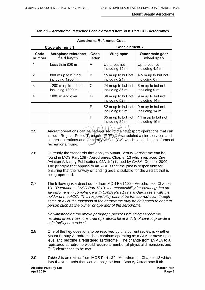
2.3 The Aerodrome Reference Code is the basis used for applying all physical
standards to runways, taxiways, aprons, runway strips and the Obstacle Limitation Surface (OLS). The Aerodrome Reference Code uses aeroplane characteristics to categorise aerodromes to ensure that the standards they are built to allow a particular aeroplane to operate. Table 1 below extracted from the CASA, MOS Part 139 - Aerodromes, Chapter 2 lists the components of the Aerodrome Reference Code.
2.4 There are now three types of aerodromes in Australia; certified, registered
and other (ALA) and the MOS Part 139 - Aerodromes specifies the standards for all three types if air transport operations are performed at the aerodrome. Mount Beauty Aerodrome is in the ‘other’ (ALA) category and is occasionally used for charter operations by flying organisations or the Air Ambulance, both of which are air transport operations.
ORDINARY COUNCIL MEETING - M6 1 JUNE 2010 7.4.2 - MOUNT BEAUTY AERODROME DRAFT MASTER PLAN
Mount Beauty Aerodrome
Airports Plus Pty Ltd Master Plan April 2010 Page 5
Table 1 – Aerodrome Reference Code extracted from MOS Part 139 - Aerodromes
2.5 Aircraft operations can be categorised into air transport operations that can
include Regular Public Transport (RPT), ie. scheduled airline services and charter operations and General Aviation (GA) which can include all forms of recreational flying.
2.6 Currently the standards that apply to Mount Beauty Aerodrome can be
found in MOS Part 139 - Aerodromes, Chapter 13 which replaced Civil Aviation Advisory Publications 92A-1(0) issued by CASA, October 2000. The principle that applies to an ALA is that the pilot is responsible for ensuring that the runway or landing area is suitable for the aircraft that is being operated.
2.7 The following is a direct quote from MOS Part 139 - Aerodromes, Chapter
13. “Pursuant to CASR Part 121B, the responsibility for ensuring that an aerodrome is in compliance with CASA Part 139 standards rests with the holder of the AOC. This responsibility cannot be transferred even though some or all of the functions of the aerodrome may be delegated to another person such as the owner or operator of the aerodrome.
Notwithstanding the above paragraph persons providing aerodrome facilities or services to aircraft operations have a duty of care to provide a safe facility or service.”
2.8 One of the key questions to be resolved by this current review is whether
Mount Beauty Aerodrome is to continue operating as a ALA or move up a level and become a registered aerodrome. The change from an ALA to a registered aerodrome would require a number of physical dimensions and OLS clearances to be met.
2.9 Table 2 is an extract from MOS Part 139 - Aerodromes, Chapter 13 which
lists the standards that would apply to Mount Beauty Aerodrome if air
ORDINARY COUNCIL MEETING - M6 1 JUNE 2010 7.4.2 - MOUNT BEAUTY AERODROME DRAFT MASTER PLAN
Mount Beauty Aerodrome
Airports Plus Pty Ltd Master Plan April 2010 Page 6
transport operations were to occur under CASR 121B. It should be noted that at this time this regulation has not come into effect. However MOS Part 139 - Aerodromes, Chapter 1 states “Aerodrome operators to whom CASR Part 121B will apply are expected to plan for and be ready to implement the Standards in Chapter 13 when the regulation comes into effect.”
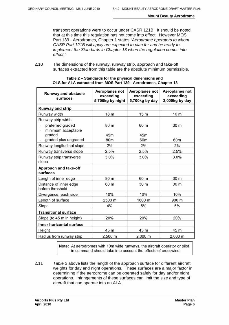
2.10 The dimensions of the runway, runway strip, approach and take-off
surfaces extracted from this table are the absolute minimum permissible.
Table 2 – Standards for the physical dimensions and OLS for ALA extracted from MOS Part 139 - Aerodromes, Chapter 13
2.11 Table 2 above lists the length of the approach surface for different aircraft
weights for day and night operations. These surfaces are a major factor in determining if the aerodrome can be operated safely for day and/or night operations. Infringements of these surfaces can limit the size and type of aircraft that can operate into an ALA.
ORDINARY COUNCIL MEETING - M6 1 JUNE 2010 7.4.2 - MOUNT BEAUTY AERODROME DRAFT MASTER PLAN

Mount Beauty Aerodrome
Airports Plus Pty Ltd Master Plan April 2010 Page 7
2.12 Additionally the dimensions of the take-off surface, although not as critical as the approach surface, can also have an influence on the ability of aircraft to be able to utilise a particular runway.
Table 3 – The physical dimensions of the OLS for take-off
from a runway extracted from MOS Part 139 - Aerodromes, Chapter 7
2.13 Figure 1 shows a typical cross section of the inner horizontal surface and
the transitional surface down to the runway strip edge.
Figure 1 – Cross section of OLS surfaces for ALA extracted from MOS Part 139 - Aerodromes, Chapter 13
2.14 The above information has been used to determine which physical
standards are applicable to Mount Beauty Aerodrome and which standards have not been met.
ORDINARY COUNCIL MEETING - M6 1 JUNE 2010 7.4.2 - MOUNT BEAUTY AERODROME DRAFT MASTER PLAN
Mount Beauty Aerodrome
Airports Plus Pty Ltd Master Plan April 2010 Page 8
3 EXISTING AERODROME INFRASTRUCTURE 3.1 Aerodrome Characteristics 3.1.1 Mount Beauty Aerodrome is owned and operated by the Alpine Shire
Council. A Committee of Management is appointed under the Local Government Act to oversee the day-to-day operations and consists of aerodrome users, the Alpine Shire and interested community representatives.
3.1.2 The aerodrome site is located approximately 1 km east of the Kiewa Valley
Highway and immediately north of the Southern Hydro regulating pondage. 3.1.3 The aerodrome site is approximately 10 ha and comprises a runway
approximately 905 m long x 22 m wide. The central portion of the runway is gravel constructed to a width of 7 m. The runway at the southeast end has a bitumen seal for approximately 300 m with an area of bitumen sprayed seal approximately 1500 m2 provided at the end of the runway for aircraft to turn. The runway is orientated on 151° grid bearing and has been designated as runway 14/32. The runway is marked with white cones evenly spaced for its entire length. The 60 m wide runway strip has been marked with white gable markers. The threshold of runway 32 is displaced approximately 200 m from the end of the bitumen sprayed seal.
3.1.4 The site falls in grade from the southeast end with a difference in levels at
the runway ends of approximately 6 metres. This gives a longitudinal grade of 0.6% overall with no dramatic change of grade for the entire length of the runway.
3.1.5 The total site is fenced with post and wire on all sides with a measured
distance between the fences running parallel to the runway of 75 m and from end to end approximately 980 m. Inside the fence on either side of the runway strip is an open unlined drain. The drain on the northeast side of the property also provides drainage for the adjoining sewerage treatment ponds.
3.1.6 The building area on the southwest side of the runway at the south end
comprises a small terminal building, a toilet block, DSE buildings and a water tank for mixing fire retardant. On the southeast side of the aerodrome there are two recently erected hangars approximately 64 m from the existing centreline of the runway and an older hangar in the corner of the aerodrome site. Access to these hangars is via a gravel road at the south end of the aerodrome.
3.1.7 Aircraft parking areas are located both sides of the terminal building and
have tie-down cables for securing light aircraft. There is a large steel framed corrugated iron building on private land on the southwest side of the runway adjacent to the aerodrome site which is used for the storage of aircraft. This land can be accessed by aircraft taxiing to and from the runway.
3.1.8 Electricity and water are connected to the buildings on the southwest side
of the runway including the terminal. There is no electricity or water currently available on the southeast side of the runway. There are no fuel
ORDINARY COUNCIL MEETING - M6 1 JUNE 2010 7.4.2 - MOUNT BEAUTY AERODROME DRAFT MASTER PLAN
Mount Beauty Aerodrome
Airports Plus Pty Ltd Master Plan April 2010 Page 9
storage facilities available for the public on the aerodrome. A carpark is located adjacent to the terminal. A locked gate provides primary access to the aerodrome on the south side of the terminal.
3.1.9 A primary windsock and signal circle is located on the northeast side of the
runway adjacent to the displaced threshold. A secondary windsock is located on the boundary fence on the northeast side at the northern end of the runway.
3.2 Current Operations 3.2.1 The aerodrome is utilised by a mixture of GA aircraft, some ultralight
aeroplanes and gliders. There are a number of aircraft permanently based at the aerodrome, all of which are less than 5,700 kg MTOW.
3.2.2 Several gliders are stored in the Mt Beauty Gliding Club’s recently
constructed hangar at the aerodrome. The gliding club has up to 40 members and operates on most weekends. Winch towing is used to launch gliders with the winch truck having permission to be parked on the extended centreline of the runway approximately 370 m north of the runway end. Gliding operations utilise the northeast side of the runway strip when launching is under way.
3.2.3 The aerodrome is used for special events in January, Easter and
November. The majority of these events involve the Benalla Gliding Club which operates up to 40 gliders on these weekends. Tow aircraft are used on these occasions.
3.2.4 A model aircraft club also uses the aerodrome and generally operates at
the southern end of the site. The site is also used as a permanent base by one or two ultralight aircraft.
3.2.5 The Air Ambulance operates a Beechcraft King Air 200 aircraft when
transferring patients and is limited to one direction operations at Mount Beauty Aerodrome; landing runway 14 and take-off is on runway 32. The aerodrome is only available for day operations. When urgent patient transfer is required and the aircraft cannot operate at Mount Beauty Aerodrome then patient transfer is normally undertaken by helicopter based at Bendigo or Latrobe Valley or by road vehicle.
3.2.6 DSE, in conjunction with the CFA, uses the aerodrome as a strategic base
for filling aircraft with fire retardant for aerial control of fires during summer. The current runway length imposes some restrictions on the MTOW of the larger aircraft used for fire suppression activities. DSE, CFA and Parks Victoria has also use the aerodrome for picking up and setting down of staff involved in fire spotting and for transporting fire fighters into the area.
3.3 Aviation Activity Forecast 3.3.1 An Aerodrome Master Plan usually includes a summary of current aviation
activity. Forecasts of future aviation activity are also provided which is a projection of growth based on current activity. No statistics of aircraft activity are kept for Mount Beauty Aerodrome. It is estimated that there are approximately 8,000 - 10,000 movements per annum at the aerodrome involving all aircraft types. A movement is defined as a landing or take-off
ORDINARY COUNCIL MEETING - M6 1 JUNE 2010 7.4.2 - MOUNT BEAUTY AERODROME DRAFT MASTER PLAN
Mount Beauty Aerodrome
Airports Plus Pty Ltd Master Plan April 2010 Page 10
from the runway. The current and proposed runway has the capacity to operate much greater than 10,000 movements per annum and therefore a forecast is not required.
4 ASSESSMENT OF MOUNT BEAUTY AERODROME AGAINST CASA
STANDARDS 4.1 Transitional Surface 4.1.1 Mount Beauty Aerodrome has been assessed against the CASA ALA
(Other Aerodromes) standards and Code 1 aerodrome standards.
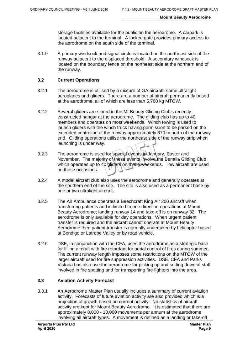
(i) The transitional surface associated with the 60 m wide runway strip is infringed by the large building on the southwestern side of the runway (refer photo # 1). The building is located approximately 45 m from the centreline of the runway and is 12.2 m high. The transitional surface for this runway commences 30 m from the centreline of the runway and slopes upward at 20% or 1:5. This means that the building penetrates the transitional surface by approximately 9 m.
Photo # 1
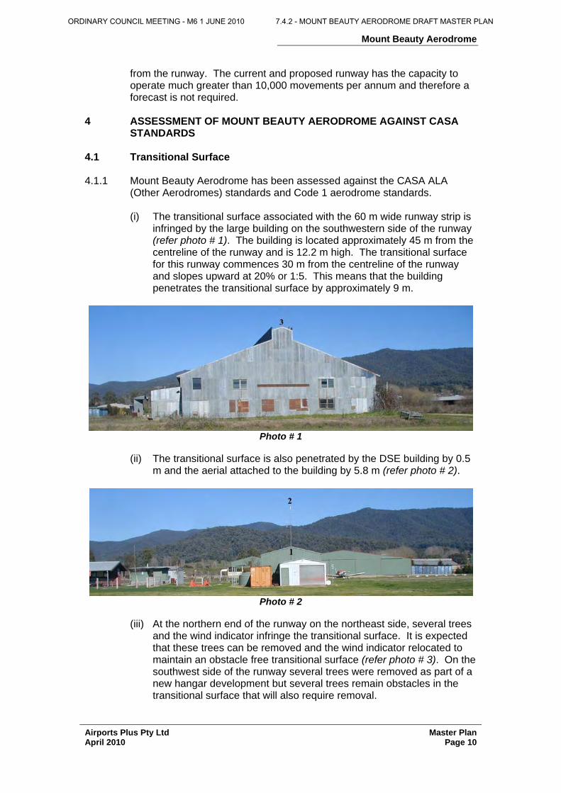
(ii) The transitional surface is also penetrated by the DSE building by 0.5
m and the aerial attached to the building by 5.8 m (refer photo # 2).
Photo # 2
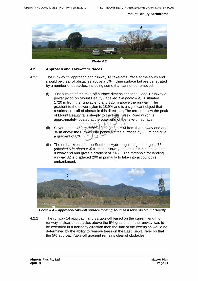
(iii) At the northern end of the runway on the northeast side, several trees
and the wind indicator infringe the transitional surface. It is expected that these trees can be removed and the wind indicator relocated to maintain an obstacle free transitional surface (refer photo # 3). On the southwest side of the runway several trees were removed as part of a new hangar development but several trees remain obstacles in the transitional surface that will also require removal.
ORDINARY COUNCIL MEETING - M6 1 JUNE 2010 7.4.2 - MOUNT BEAUTY AERODROME DRAFT MASTER PLAN
Mount Beauty Aerodrome
Airports Plus Pty Ltd Master Plan April 2010 Page 11
Photo # 3
4.2 Approach and Take-off Surfaces
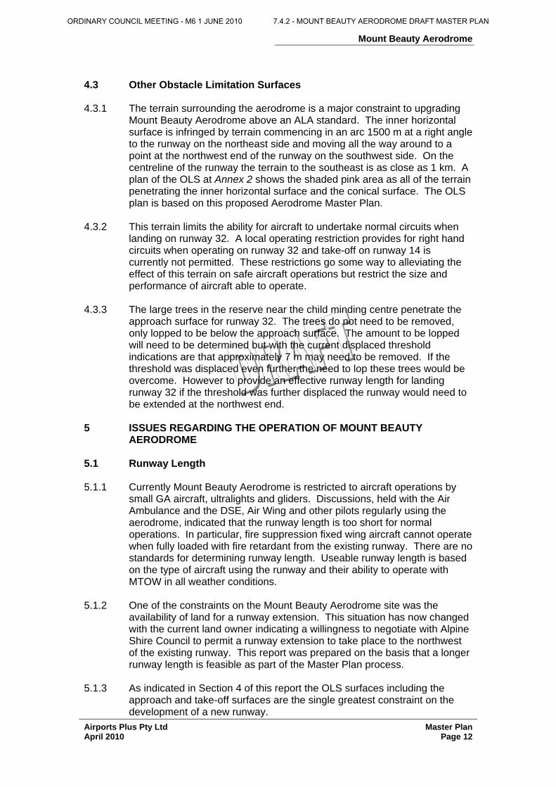
4.2.1 The runway 32 approach and runway 14 take-off surface at the south end
should be clear of obstacles above a 5% incline surface but are penetrated by a number of obstacles, including some that cannot be removed:
(i) Just outside of the take-off surface dimensions for a Code 1 runway a
power pylon on Mount Beauty (labelled 1 in photo # 4) is situated 1720 m from the runway end and 325 m above the runway. The gradient to the power pylon is 18.9% and is a significant object that restricts take-off of aircraft in this direction. The terrain below the peak of Mount Beauty falls steeply to the Falls Creek Road which is approximately located at the outer end of the take-off surface.
(ii) Several trees 460 m (labelled 3 in photo # 4) from the runway end and
36 m above the runway end penetrate the surfaces by 6.5 m and give a gradient of 8%.
(iii) The embankment for the Southern Hydro regulating pondage is 73 m
(labelled 5 in photo # 4) from the runway end and is 5.5 m above the runway end and gives a gradient of 7.6%. The threshold for landing runway 32 is displaced 200 m primarily to take into account this embankment.
Photo # 4 – Approach/Take-off surface looking southeast towards Mount Beauty
4.2.2 The runway 14 approach and 32 take-off based on the current length of
runway is clear of obstacles above the 5% gradient. If the runway was to be extended in a northerly direction then the limit of the extension would be determined by the ability to remove trees on the East Kiewa River so that the 5% approach/take-off gradient remains clear of obstacles.
ORDINARY COUNCIL MEETING - M6 1 JUNE 2010 7.4.2 - MOUNT BEAUTY AERODROME DRAFT MASTER PLAN
Mount Beauty Aerodrome
Airports Plus Pty Ltd Master Plan April 2010 Page 12
4.3 Other Obstacle Limitation Surfaces 4.3.1 The terrain surrounding the aerodrome is a major constraint to upgrading
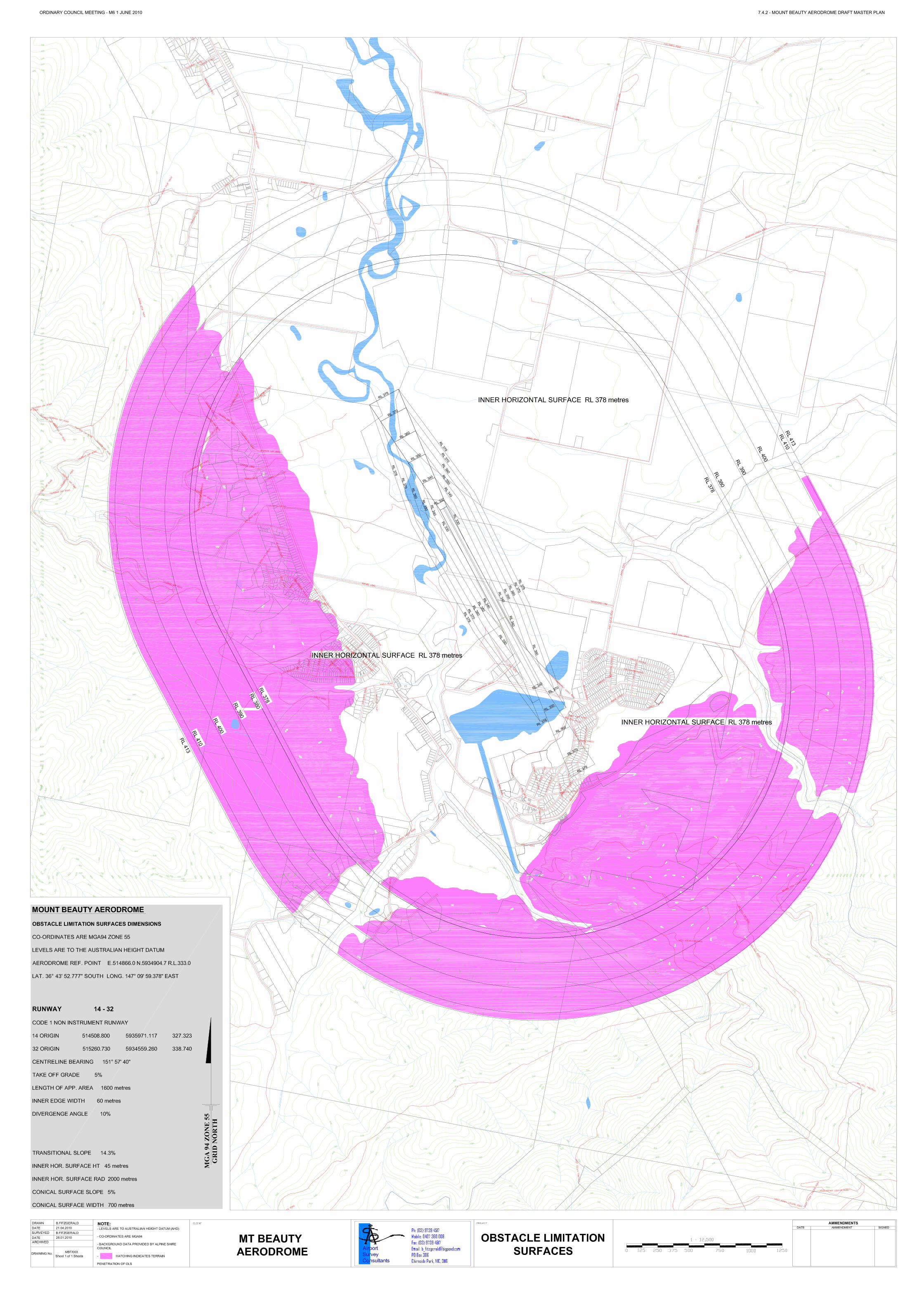
Mount Beauty Aerodrome above an ALA standard. The inner horizontal surface is infringed by terrain commencing in an arc 1500 m at a right angle to the runway on the northeast side and moving all the way around to a point at the northwest end of the runway on the southwest side. On the centreline of the runway the terrain to the southeast is as close as 1 km. A plan of the OLS at Annex 2 shows the shaded pink area as all of the terrain penetrating the inner horizontal surface and the conical surface. The OLS plan is based on this proposed Aerodrome Master Plan.
4.3.2 This terrain limits the ability for aircraft to undertake normal circuits when
landing on runway 32. A local operating restriction provides for right hand circuits when operating on runway 32 and take-off on runway 14 is currently not permitted. These restrictions go some way to alleviating the effect of this terrain on safe aircraft operations but restrict the size and performance of aircraft able to operate.
4.3.3 The large trees in the reserve near the child minding centre penetrate the
approach surface for runway 32. The trees do not need to be removed, only lopped to be below the approach surface. The amount to be lopped will need to be determined but with the current displaced threshold indications are that approximately 7 m may need to be removed. If the threshold was displaced even further the need to lop these trees would be overcome. However to provide an effective runway length for landing runway 32 if the threshold was further displaced the runway would need to be extended at the northwest end.
5 ISSUES REGARDING THE OPERATION OF MOUNT BEAUTY
AERODROME 5.1 Runway Length 5.1.1 Currently Mount Beauty Aerodrome is restricted to aircraft operations by
small GA aircraft, ultralights and gliders. Discussions, held with the Air Ambulance and the DSE, Air Wing and other pilots regularly using the aerodrome, indicated that the runway length is too short for normal operations. In particular, fire suppression fixed wing aircraft cannot operate when fully loaded with fire retardant from the existing runway. There are no standards for determining runway length. Useable runway length is based on the type of aircraft using the runway and their ability to operate with MTOW in all weather conditions.
5.1.2 One of the constraints on the Mount Beauty Aerodrome site was the
availability of land for a runway extension. This situation has now changed with the current land owner indicating a willingness to negotiate with Alpine Shire Council to permit a runway extension to take place to the northwest of the existing runway. This report was prepared on the basis that a longer runway length is feasible as part of the Master Plan process.
5.1.3 As indicated in Section 4 of this report the OLS surfaces including the
approach and take-off surfaces are the single greatest constraint on the development of a new runway.
ORDINARY COUNCIL MEETING - M6 1 JUNE 2010 7.4.2 - MOUNT BEAUTY AERODROME DRAFT MASTER PLAN
Mount Beauty Aerodrome
Airports Plus Pty Ltd Master Plan April 2010 Page 13
5.2 Runway Strip 5.2.1 The runway strip at 60 m wide currently fits neatly between the fences
measured by survey at approximately 75 m. However the area required to be maintained to ensure safe operations of aircraft inside the runway strip is not graded to the correct standards. All holes and depressions that could damage the undercarriage of taxiing aircraft need to be filled and compacted.
5.2.2 The gliding operations undertaken on the aerodrome are also restricted by
the width of the runway strip. To enhance safety of gliding operations it is normal practice that when gliding operations are contained wholly within an existing runway strip used for powered aircraft that the glider runway strip is fixed on one side by the edge of the runway and on the other by the existing runway strip markers being adjusted outwards as necessary. This adjustment cannot occur at Mount Beauty Aerodrome due to the location of an open unlined drain immediately outside the runway strip markers and the post and wire fence between the aerodrome site and the sewerage treatment farm.
5.3 Aircraft Noise 5.3.1 Aircraft noise generated by the operation of aircraft at Mount Beauty
Aerodrome has not been a concern expressed by the local community. The restriction on aircraft operations making a right hand circuit for runway 32 assists in reducing the impact of aircraft noise on the township of Mount Beauty.
5.3.2 An Australian Noise Exposure Forecast (ANEF) study has not been
requested as part of this Master Plan study. An ANEF is based on aircraft types expected to operate over a forecast period, usually 15 years. It is not expected that there will be a change of aircraft types operating at Mount Beauty Aerodrome in that time period. Therefore it is not expected that there will be an increase in the noise generated by aircraft operations at the aerodrome.
5.4 Feasibility of Night Operations 5.4.1 The Air Ambulance requested that the Alpine Shire Council investigate, as
part of this Master Plan, the feasibility of providing runway lighting to enable aircraft operations to be undertaken at night. Due to the infringements of the OLS, particularly the transitional surface and the inner horizontal and conical surfaces, it would not be feasible to establish permanent runway lighting. A major constraint for providing permanent runway lighting would be the monetary cost of providing obstacle lighting on terrain surrounding the aerodrome and buildings that are penetrating the OLS.
5.4.2 The provision of portable battery operated runway lights is feasible.
However, an investigation would need to be undertaken on the monetary cost of maintaining this type of lighting versus the number of times that the lights would actually for the Air Ambulance emergency patient transfer.
5.4.3 Approximately 50 lights would be required that would need to be
maintained fully serviceable at all times so that when required the lights
ORDINARY COUNCIL MEETING - M6 1 JUNE 2010 7.4.2 - MOUNT BEAUTY AERODROME DRAFT MASTER PLAN
Mount Beauty Aerodrome
Airports Plus Pty Ltd Master Plan April 2010 Page 14
could be laid out on the runway edge and ends and switched on. It is not envisaged that if portable lights were introduced that they would remain in place on the runway when not in use.
5.5 Provision of an Instrument Approach Procedure 5.5.1 A further request from the Air Ambulance was for the Alpine Shire Council
to investigate the feasibility of providing a GPS Non-Precision Approach Procedure (NPA) for landing on runway 14. A suggested parameter for the design of the procedure was to have a minima of 1100 ft AGL at 5 km distance from the threshold of runway 14.
5.5.2 A procedure designer was requested to undertake a feasibility investigation
into whether or not a procedure could be designed for Mount Beauty Aerodrome. Due to terrain restrictions it was determined that it was not possible to provide a procedure design that met the required minima.
5.5.3 A further constraint on the provision of a GPS NPA is that Mount Beauty
Aerodrome would need to become a registered aerodrome for this procedure to be published. There are too many physical constraints on the aerodrome and in the vicinity of the aerodrome including terrain that would prevent the aerodrome from meeting the registered aerodrome standards.
5.6 Building Development 5.6.1 The terminal building and public toilets and the DSE building have good
road access. There are ample aircraft parking areas around the terminal building.
5.6.2 There is land available for further hangar development immediately behind
the DSE building. There is also land available for development on the opposite side of the access road which is part of the aerodrome site.
5.6.3 The Alpine Shire Council has approved the erection of hangars on the
northeast side of Mount Beauty Aerodrome. These hangars have been erected closer to the runway centreline than the existing small hangar in the east corner of the aerodrome site and inside the proposed building line that was established in the first draft Master Plan.
5.6.4 The Gliding Club building, which is the building closest to the centreline on
the northeast side of the runway, is 64.2 m from the centreline of the existing runway and is 2 m below the transitional surface for the existing runway. The privately owned corrugated iron shed on the southwest side of the runway is located 45.3 m from the centreline of the runway; giving a total width between the buildings of 109.5 m. The Gliding Club hangar and the proposed duplication of the hangar closer to the runway centreline is now the limiting factor to determining the centreline of any new runway layout.
5.6.5 The Alpine Shire Council has approved a subdivision allowing the erection
of hangars on private land adjacent to the aerodrome, north of the large privately owned corrugated iron shed. A building line was established for this site in relation to the future operations of the aerodrome in the 2005 draft Master Plan. This building line was located 60 m from the centreline of the existing runway and this would allow a 6 m building to be erected
ORDINARY COUNCIL MEETING - M6 1 JUNE 2010 7.4.2 - MOUNT BEAUTY AERODROME DRAFT MASTER PLAN
Mount Beauty Aerodrome
Airports Plus Pty Ltd Master Plan April 2010 Page 15
behind this line. This building line is still applicable for this development and any future development on the southwest side of the runway as the runway strip will remain 60 m wide into the foreseeable future.
5.6.6 The building line for the northeast side of the runway should also be
established at 60 m from the centreline of the existing runway. The Gliding Club hangar is situated inside this building line but is well below the 6 m building height and therefore does not infringe the transitional surface.
6 MASTER PLAN DEVELOPMENT STRATEGY 6.1 Criteria for Development 6.1.1 Mount Beauty Aerodrome meets the needs of current aircraft operators
permanently based at the aerodrome. The aerodrome is utilised by the Air Ambulance and DSE in emergency situations as it is the only runway in the region that is marginally suitable for their aircraft operations. For the runway to be utilised on a more frequent basis by these emergency services the runway needs to be lengthened and widened and provided with an all weather surface, preferably a bitumen sprayed sealed surface.
6.1.2 The demand for future hangar sites on and adjacent to the aerodrome
needs to be controlled in a manner that ensures that aircraft operations are not compromised.
6.2 Regulatory Framework for Mount Beauty Aerodrome 6.2.1 Mount Beauty Aerodrome has too many physical constraints which prevent
it from meeting the standards required to become a registered aerodrome. It has been determined in the process of undertaking this Master Plan study that there are no clear advantages in seeking to change the regulatory status of the aerodrome from an ALA (Other Aerodrome).
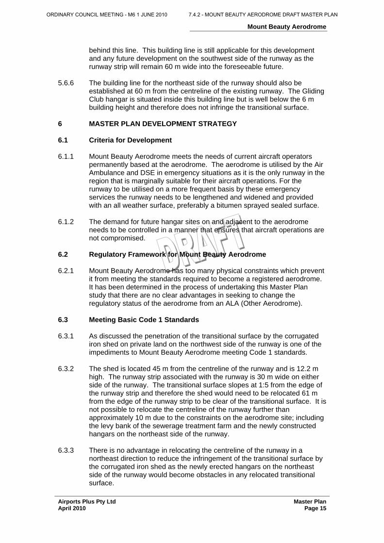
6.3 Meeting Basic Code 1 Standards 6.3.1 As discussed the penetration of the transitional surface by the corrugated
iron shed on private land on the northwest side of the runway is one of the impediments to Mount Beauty Aerodrome meeting Code 1 standards.
6.3.2 The shed is located 45 m from the centreline of the runway and is 12.2 m
high. The runway strip associated with the runway is 30 m wide on either side of the runway. The transitional surface slopes at 1:5 from the edge of the runway strip and therefore the shed would need to be relocated 61 m from the edge of the runway strip to be clear of the transitional surface. It is not possible to relocate the centreline of the runway further than approximately 10 m due to the constraints on the aerodrome site; including the levy bank of the sewerage treatment farm and the newly constructed hangars on the northeast side of the runway.
6.3.3 There is no advantage in relocating the centreline of the runway in a
northeast direction to reduce the infringement of the transitional surface by the corrugated iron shed as the newly erected hangars on the northeast side of the runway would become obstacles in any relocated transitional surface.
ORDINARY COUNCIL MEETING - M6 1 JUNE 2010 7.4.2 - MOUNT BEAUTY AERODROME DRAFT MASTER PLAN
Mount Beauty Aerodrome
Airports Plus Pty Ltd Master Plan April 2010 Page 16
6.3.4 The open unlined drain, which provides drainage from the sewerage treatment farm, along the northeast boundary of the aerodrome site needs to be relocated to enhance the safety of gliding operations in particular.
6.4 Runway Length and Width Development 6.4.1 Runway length is not determined by standards published by CASA but by
the size of aircraft using the runway. The Air Ambulance and DSE have indicated that their preference is to have a runway length of at least 1300 m to enable their aircraft to operate at MTOW in high temperature conditions. If the runway was to be lengthened then private land at the northwest end of the runway would need to be made available by the landowner.
6.4.2 Any extension to the runway should be to the maximum length within the
constraints of the available land. By extending the runway beyond 1300 m it would be possible to also relocate the displaced threshold for runway 32 further to the northwest so that a standard Code 1 obstacle free approach surface with a gradient of 5% becomes available. This would enable a greater range of aircraft types to land into the wind on runway 32 with a suitable approach area for turning base and final approach which is not currently available.
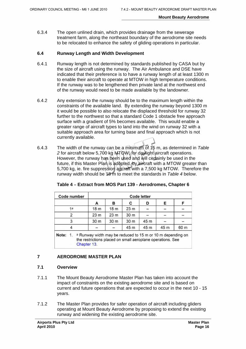
6.4.3 The width of the runway can be a minimum of 15 m, as determined in Table
2 for aircraft below 5,700 kg MTOW, for daylight aircraft operations. However, the runway has been used and will certainly be used in the future, if this Master Plan is adopted, by aircraft with a MTOW greater than 5,700 kg, ie. fire suppression aircraft with a 7,500 kg MTOW. Therefore the runway width should be 18 m to meet the standards in Table 4 below.
Table 4 – Extract from MOS Part 139 - Aerodromes, Chapter 6
7 AERODROME MASTER PLAN 7.1 Overview 7.1.1 The Mount Beauty Aerodrome Master Plan has taken into account the
impact of constraints on the existing aerodrome site and is based on current and future operations that are expected to occur in the next 10 - 15 years.
7.1.2 The Master Plan provides for safer operation of aircraft including gliders
operating at Mount Beauty Aerodrome by proposing to extend the existing runway and widening the existing aerodrome site.
ORDINARY COUNCIL MEETING - M6 1 JUNE 2010 7.4.2 - MOUNT BEAUTY AERODROME DRAFT MASTER PLAN
Mount Beauty Aerodrome
Airports Plus Pty Ltd Master Plan April 2010 Page 17
7.1.3 The establishment of a displaced threshold further to the northwest of the
existing threshold on runway 32 would enable aircraft to land in a safer manner and further enhances the ability to develop aerodrome land at the southeast end of the aerodrome site.
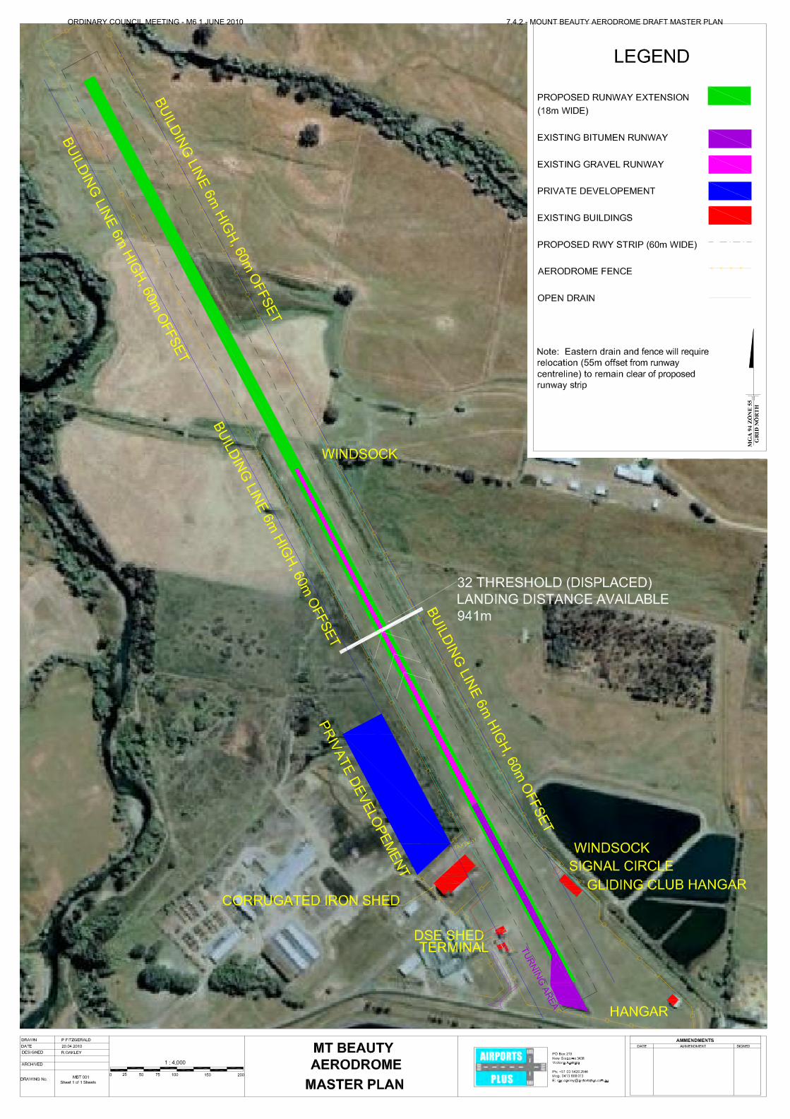
7.2 Details of Aerodrome Development 7.2.1 Runway Length 7.2.1.1 The proposed runway length in this Master Plan is 1540 m and is contained
in a runway strip which has an overall length of 1600 m. This means that the existing runway will need to be extended approximately 700 m into private land at the northwest end of the existing aerodrome site.
7.2.1.2 In discussions with the owner of the land to the northwest of the aerodrome
site it was clear that the benefits of making land available for the runway extension were understood. The landowner indicated that discussions with the Alpine Shire Council, to negotiate the transfer of a suitable parcel of land to allow the Master Plan to be implemented, could proceed.
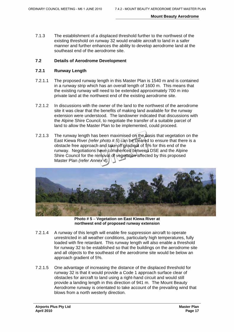
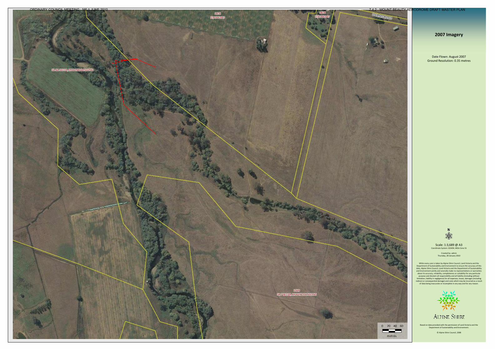
7.2.1.3 The runway length has been maximised on the basis that vegetation on the
East Kiewa River (refer photo # 5) can be cleared to ensure that there is a obstacle free approach and take-off gradient of 5% for this end of the runway. Negotiations have commenced between DSE and the Alpine Shire Council for the removal of vegetation affected by this proposed Master Plan (refer Annex 4).
Photo # 5 – Vegetation on East Kiewa River at northwest end of proposed runway extension
7.2.1.4 A runway of this length will enable fire suppression aircraft to operate
unrestricted in all weather conditions, particularly high temperatures, fully loaded with fire retardant. This runway length will also enable a threshold for runway 32 to be established so that the buildings on the aerodrome site and all objects to the southeast of the aerodrome site would be below an approach gradient of 5%.
7.2.1.5 One advantage of increasing the distance of the displaced threshold for
runway 32 is that it would provide a Code 1 approach surface clear of obstacles for aircraft to land using a right-hand circuit and would still provide a landing length in this direction of 941 m. The Mount Beauty Aerodrome runway is orientated to take account of the prevailing wind that blows from a north westerly direction.
ORDINARY COUNCIL MEETING - M6 1 JUNE 2010 7.4.2 - MOUNT BEAUTY AERODROME DRAFT MASTER PLAN
Mount Beauty Aerodrome
Airports Plus Pty Ltd Master Plan April 2010 Page 18
7.2.1.6 The second advantage for providing this increased displaced threshold is that hangar construction could occur on both sides of the runway up to the building line for 6 m high buildings and closer to the runway for buildings below 6 m in height. These buildings would not interfere with normal aircraft landing operations as aircraft would be overflying this section of the aerodrome to land on the displaced threshold. Take-off in a northwest direction from runway 32 would allow aircraft to use the full length of the proposed runway without restriction.
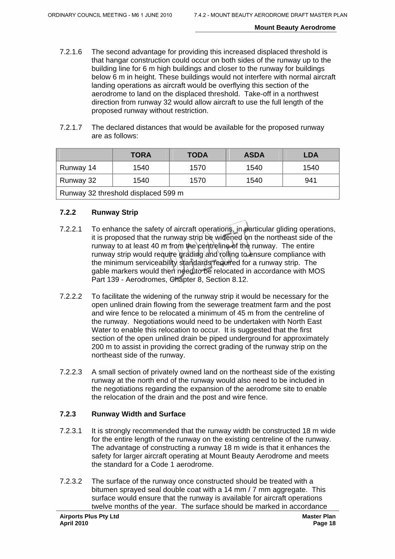
7.2.1.7 The declared distances that would be available for the proposed runway
are as follows: TORA TODA ASDA LDA
Runway 14 1540 1570 1540 1540
Runway 32 1540 1570 1540 941
Runway 32 threshold displaced 599 m 7.2.2 Runway Strip 7.2.2.1 To enhance the safety of aircraft operations, in particular gliding operations,
it is proposed that the runway strip be widened on the northeast side of the runway to at least 40 m from the centreline of the runway. The entire runway strip would require grading and rolling to ensure compliance with the minimum serviceability standards required for a runway strip. The gable markers would then need to be relocated in accordance with MOS Part 139 - Aerodromes, Chapter 8, Section 8.12.
7.2.2.2 To facilitate the widening of the runway strip it would be necessary for the
open unlined drain flowing from the sewerage treatment farm and the post and wire fence to be relocated a minimum of 45 m from the centreline of the runway. Negotiations would need to be undertaken with North East Water to enable this relocation to occur. It is suggested that the first section of the open unlined drain be piped underground for approximately 200 m to assist in providing the correct grading of the runway strip on the northeast side of the runway.
7.2.2.3 A small section of privately owned land on the northeast side of the existing
runway at the north end of the runway would also need to be included in the negotiations regarding the expansion of the aerodrome site to enable the relocation of the drain and the post and wire fence.
7.2.3 Runway Width and Surface 7.2.3.1 It is strongly recommended that the runway width be constructed 18 m wide
for the entire length of the runway on the existing centreline of the runway. The advantage of constructing a runway 18 m wide is that it enhances the safety for larger aircraft operating at Mount Beauty Aerodrome and meets the standard for a Code 1 aerodrome.
7.2.3.2 The surface of the runway once constructed should be treated with a
bitumen sprayed seal double coat with a 14 mm / 7 mm aggregate. This surface would ensure that the runway is available for aircraft operations twelve months of the year. The surface should be marked in accordance
ORDINARY COUNCIL MEETING - M6 1 JUNE 2010 7.4.2 - MOUNT BEAUTY AERODROME DRAFT MASTER PLAN
Mount Beauty Aerodrome
Airports Plus Pty Ltd Master Plan April 2010 Page 19
with the standards in MOS Part 139 - Aerodromes, Chapter 8 and include a white painted centreline, runway designation numbers, a displaced threshold marking for runway 32 and threshold markings for runway 14. A runway marking plan should be produced to ensure that the runway markings are laid out correctly.
7.2.3.3 The constructed pavement thickness should be based on the strength
required for the largest aircraft that is going to operate on the runway in the next 15 years. The design of the pavement thickness should be undertaken by a pavement engineer who specialises in designing aircraft pavements. The grading design of the runway should be prepared based on MOS Part 139 - Aerodromes, Chapter 6.
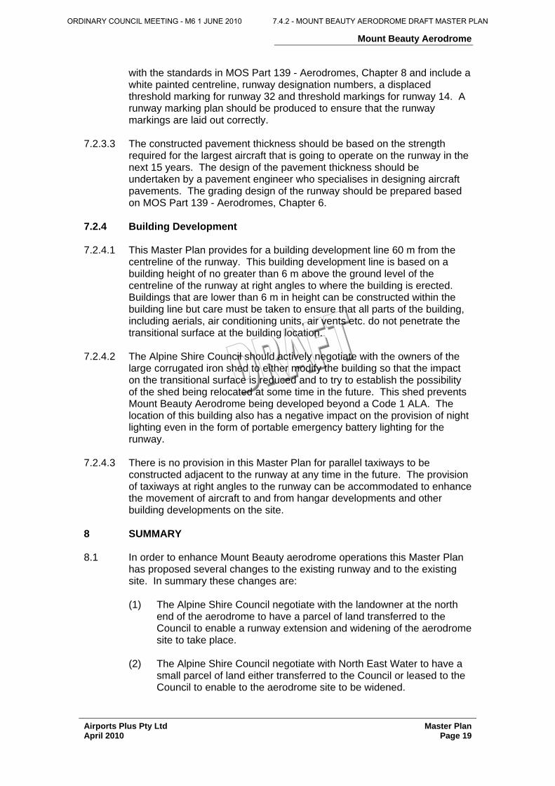
7.2.4 Building Development 7.2.4.1 This Master Plan provides for a building development line 60 m from the
centreline of the runway. This building development line is based on a building height of no greater than 6 m above the ground level of the centreline of the runway at right angles to where the building is erected. Buildings that are lower than 6 m in height can be constructed within the building line but care must be taken to ensure that all parts of the building, including aerials, air conditioning units, air vents etc. do not penetrate the transitional surface at the building location.
7.2.4.2 The Alpine Shire Council should actively negotiate with the owners of the
large corrugated iron shed to either modify the building so that the impact on the transitional surface is reduced and to try to establish the possibility of the shed being relocated at some time in the future. This shed prevents Mount Beauty Aerodrome being developed beyond a Code 1 ALA. The location of this building also has a negative impact on the provision of night lighting even in the form of portable emergency battery lighting for the runway.
7.2.4.3 There is no provision in this Master Plan for parallel taxiways to be
constructed adjacent to the runway at any time in the future. The provision of taxiways at right angles to the runway can be accommodated to enhance the movement of aircraft to and from hangar developments and other building developments on the site.
8 SUMMARY 8.1 In order to enhance Mount Beauty aerodrome operations this Master Plan
has proposed several changes to the existing runway and to the existing site. In summary these changes are:
(1) The Alpine Shire Council negotiate with the landowner at the north
end of the aerodrome to have a parcel of land transferred to the Council to enable a runway extension and widening of the aerodrome site to take place.
(2) The Alpine Shire Council negotiate with North East Water to have a
small parcel of land either transferred to the Council or leased to the Council to enable to the aerodrome site to be widened.
ORDINARY COUNCIL MEETING - M6 1 JUNE 2010 7.4.2 - MOUNT BEAUTY AERODROME DRAFT MASTER PLAN
Mount Beauty Aerodrome
Airports Plus Pty Ltd Master Plan April 2010 Page 20
(3) The Alpine Shire Council negotiate with DSE to remove vegetation along a section of East Kiewa River to enable the runway to be extended and to maintain an obstacle free approach gradient of 5%.
(4) The runway strip to be constructed on the existing centreline to
achieve a total length of 1600 m. The runway strip should be graded to enable the minimum standards to be met for aircraft and gliding operations.
(5) The runway to be constructed within the runway strip based on the
existing centreline and extended for approximately 700 m to provide a total runway length of 1540 m. The runway should be constructed 18 m wide.
(6) Once the runway is extended, the threshold of runway 32 should be
displaced 599 m from the south end to provide a landing length of 941 m with a Code 1 approach surface with an obstacle free gradient of 5%.
(7) Provide the runway surface with a bitumen sprayed two coat seal
using a 14 mm / 7 mm aggregate. (8) Provide runway markings on the runway surface to ensure that
aircraft operate in a safer manner. (9) The open unlined drain on the northeast side of the runway needs to
be relocated to a minimum of 45 m from the centreline of the runway. The runway strip on the northeast side of the runway needs to be widened to approximately 40 m to cater for gliding operations so that they can be undertaken in a safer manner.
(10) To further assist the gliding operations the first 200 m of the open
unlined drain should be piped. (11) The post and wire fence marking the boundary of the aerodrome also
needs to be relocated outside of the open unlined drain to be outside of the transitional surface of the runway strip.
(12) Maintain a 60 m building line from the centreline of the runway which
would enable a 6 m high building to be constructed adjacent to the runway. Buildings that are lower in height may be constructed closer to the runway but only after careful analysis that aircraft operations are not affected and that the OLS is not penetrated.
ORDINARY COUNCIL MEETING - M6 1 JUNE 2010 7.4.2 - MOUNT BEAUTY AERODROME DRAFT MASTER PLAN
Mount Beauty Aerodrome
Airports Plus Pty Ltd Master Plan April 2010 Page 21
Annex 1 – Mount Beauty Aerodrome Illustrated Master Plan
ORDINARY COUNCIL MEETING - M6 1 JUNE 2010 7.4.2 - MOUNT BEAUTY AERODROME DRAFT MASTER PLAN
ORDINARY COUNCIL MEETING - M6 1 JUNE 2010 7.4.2 - MOUNT BEAUTY AERODROME DRAFT MASTER PLAN
Mount Beauty Aerodrome
Airports Plus Pty Ltd Master Plan April 2010 Page 23
Annex 2 – OLS for Mount Beauty Aerodrome drawn to Code 1 Standards
ORDINARY COUNCIL MEETING - M6 1 JUNE 2010 7.4.2 - MOUNT BEAUTY AERODROME DRAFT MASTER PLAN
ORDINARY COUNCIL MEETING - M6 1 JUNE 2010 7.4.2 - MOUNT BEAUTY AERODROME DRAFT MASTER PLAN
Mount Beauty Aerodrome
Airports Plus Pty Ltd Master Plan April 2010 Page 25
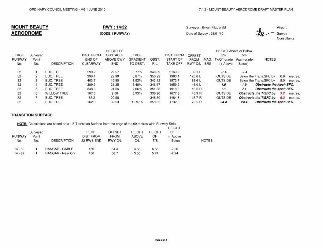
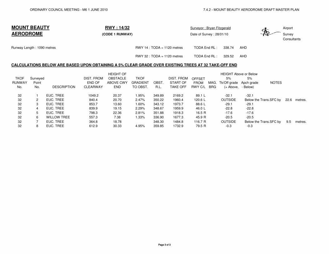
Annex 3 – OLS Survey
ORDINARY COUNCIL MEETING - M6 1 JUNE 2010 7.4.2 - MOUNT BEAUTY AERODROME DRAFT MASTER PLAN
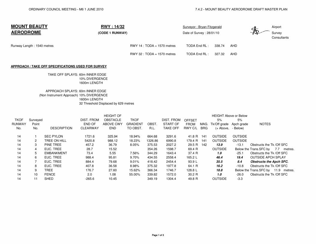
MOUNT BEAUTY RWY : 14/32 Surveyor : Bryan Fitzgerald Airport
AERODROME (CODE 1 RUNWAY) Date of Survey : 28/01/10 Survey
Consultants
Runway Length : 1540 metres RWY 14 : TODA = 1570 metres TODA End RL : 338.74 AHD
RWY 32 : TODA = 1570 metres TODA End RL : 327.32 AHD
APPROACH / TAKE OFF SPECIFICATIONS USED FOR SURVEY
TAKE OFF SPLAYS: 60m INNER EDGE
10% DIVERGENCE
1600m LENGTH
APPROACH SPLAYS: 60m INNER EDGE
(Non Instrument Approach) 10% DIVERGENCE
1600m LENGTH
32 Threshold Displaced by 629 metres
HEIGHT OF
TKOF Surveyed DIST. FROM OBSTACLE TKOF DIST. FROM 5% 5%
RUNWAY Point END OF ABOVE CWY GRADIENT OBST. START OF MAG. Tk/Off grade Apch grade NOTES
No. No. DESCRIPTION CLEARWAY END TO OBST. R.L. TAKE OFF BRG (+ Above, - Below)
14 1 SEC PYLON 1721.6 325.94 18.94% 664.68 3291.6 41.8 R 141 OUTSIDE OUTSIDE
HEIGHT Above or Below
OFFSET
FROM
RWY C/L
Page 1 of 3
14 1 SEC PYLON 1721.6 325.94 18.94% 664.68 3291.6 41.8 R 141 OUTSIDE OUTSIDE
14 2 TREE ON HILL 5420.8 988.12 18.23% 1326.86 6990.8 179.4 R 141 OUTSIDE OUTSIDE
14 3 PINE TREE 457.2 36.79 8.05% 375.53 2027.2 29.5 R 142 13.9 -13.1 Obstructs the Tk /Off SFC
14 4 EUC. TREE 28.7 15.52 354.26 1598.7 69.4 R OUTSIDE Below the Trans.SFC by 7.7 metres.
14 5 EMBANKMENT 73.4 5.55 7.56% 344.29 1643.4 37.4 R 1.9 -25.1 Obstructs the Tk /Off SFC
14 6 EUC. TREE 988.4 95.81 9.70% 434.55 2558.4 165.2 L 46.4 19.4 OUTSIDE APCH SPLAY
14 7 EUC. TREE 884.4 79.68 9.01% 418.42 2454.4 93.9 L 35.5 8.4 Obstructs the Apch SFC.
14 8 EUC. TREE 407.8 36.58 8.98% 375.32 1977.8 64.1 R 16.2 -10.8 Obstructs the Tk /Off SFC
14 9 TREE 176.7 27.60 15.62% 366.34 1746.7 128.8 L 18.8 Below the Trans.SFC by 11.9 metres.
14 10 FENCE 2.0 1.08 55.00% 339.82 1572.0 30.2 R 1.0 -26.0 Obstructs the Tk /Off SFC
14 11 SHED -265.6 10.45 349.19 1304.4 49.8 R OUTSIDE -3.3
Page 1 of 3
ORDINARY COUNCIL MEETING - M6 1 JUNE 2010 7.4.2 - MOUNT BEAUTY AERODROME DRAFT MASTER PLAN
MOUNT BEAUTY RWY : 14/32 Surveyor : Bryan Fitzgerald Airport
AERODROME (CODE 1 RUNWAY) Date of Survey : 28/01/10 Survey
Consultants
HEIGHT OF
TKOF Surveyed DIST. FROM OBSTACLE TKOF DIST. FROM 5% 5%
RUNWAY Point END OF ABOVE CWY GRADIENT OBST. START OF MAG. Tk/Off grade Apch grade NOTES
No. No. DESCRIPTION CLEARWAY END TO OBST. R.L. TAKE OFF BRG (+ Above, - Below)
32 1 EUC. TREE 599.2 22.57 3.77% 349.89 2169.2 89.1 L -7.4 -7.4
32 2 EUC. TREE 390.4 22.90 5.87% 350.22 1960.4 120.6 L OUTSIDE Below the Trans.SFC by 6.9 metres.
32 3 EUC. TREE 403.7 15.80 3.92% 343.12 1973.7 88.6 L OUTSIDE Below the Trans.SFC by 8.0 metres.
32 4 EUC. TREE 389.9 21.35 5.48% 348.67 1959.9 46.0 L 1.9 1.9 Obstructs the Apch SFC.
32 5 EUC. TREE 348.3 24.56 7.06% 351.88 1918.3 16.5 R 7.1 7.1 Obstructs the Apch SFC.
32 6 WILLOW TREE 107.3 9.58 8.93% 336.90 1677.3 45.9 R OUTSIDE Obstructs the T/SFC by 3.2 metres.
32 7 EUC. TREE -85.2 20.98 348.30 1484.8 116.7 R OUTSIDE Obstructs the T/SFC by 6.2 metres.
32 8 EUC. TREE 162.9 32.53 19.97% 359.85 1732.9 79.5 R 24.4 24.4 Obstructs the Apch SFC.
TRANSITION SURFACE
NOTE: Calculations are based on a 1:5 Transition Surface from the edge of the 60 metres wide Runway Strip.
HEIGHT
Surveyed PERP. OFFSET HEIGHT HEIGHT DIFF.
RUNWAY Point DIST FROM FROM ABOVE OF + Above
No. No. DESCRIPTION 32 RWS END RWY C/L C/L T/S - Below NOTES
OFFSET
FROM
RWY C/L
HEIGHT Above or Below
Page 2 of 3
No. No. DESCRIPTION 32 RWS END RWY C/L C/L T/S - Below NOTES
14 - 32 1 HANGAR - GABLE 150 64.4 4.68 6.88 -2.20
14 - 32 1 HANGAR - Near Cnr 150 58.7 3.50 5.74 -2.24
Page 2 of 3
ORDINARY COUNCIL MEETING - M6 1 JUNE 2010 7.4.2 - MOUNT BEAUTY AERODROME DRAFT MASTER PLAN
MOUNT BEAUTY RWY : 14/32 Surveyor : Bryan Fitzgerald Airport
AERODROME (CODE 1 RUNWAY) Date of Survey : 28/01/10 Survey
Consultants
Runway Length : 1090 metres RWY 14 : TODA = 1120 metres TODA End RL : 338.74 AHD
RWY 32 : TODA = 1120 metres TODA End RL : 329.52 AHD
CALCULATIONS BELOW ARE BASED UPON OBTAINING A 5% CLEAR GRADE OVER EXISTING TREES AT 32 TAKE-OFF END
HEIGHT OF
TKOF Surveyed DIST. FROM OBSTACLE TKOF DIST. FROM 5% 5%
RUNWAY Point END OF ABOVE CWY GRADIENT OBST. START OF MAG. Tk/Off grade Apch grade NOTES
No. No. DESCRIPTION CLEARWAY END TO OBST. R.L. TAKE OFF BRG (+ Above, - Below)
32 1 EUC. TREE 1049.2 20.37 1.95% 349.89 2169.2 89.1 L -32.1 -32.1
32 2 EUC. TREE 840.4 20.70 2.47% 350.22 1960.4 120.6 L OUTSIDE Below the Trans.SFC by 22.6 metres.
32 3 EUC. TREE 853.7 13.60 1.60% 343.12 1973.7 88.6 L -29.1 -29.1
32 4 EUC. TREE 839.9 19.15 2.29% 348.67 1959.9 46.0 L -22.8 -22.8
32 5 EUC. TREE 798.3 22.36 2.81% 351.88 1918.3 16.5 R -17.6 -17.6
32 6 WILLOW TREE 557.3 7.38 1.33% 336.90 1677.3 45.9 R -20.5 -20.5
32 7 EUC. TREE 364.8 18.78 348.30 1484.8 116.7 R OUTSIDE Below the Trans.SFC by 9.5 metres.
32 8 EUC. TREE 612.9 30.33 4.95% 359.85 1732.9 79.5 R -0.3 -0.3
HEIGHT Above or Below
OFFSET
FROM
RWY C/L
Page 3 of 3Page 3 of 3
ORDINARY COUNCIL MEETING - M6 1 JUNE 2010 7.4.2 - MOUNT BEAUTY AERODROME DRAFT MASTER PLAN
Mount Beauty Aerodrome
Airports Plus Pty Ltd Master Plan April 2010 Page 27
Annex 4 – Plan of affected vegetation northwest end
ORDINARY COUNCIL MEETING - M6 1 JUNE 2010 7.4.2 - MOUNT BEAUTY AERODROME DRAFT MASTER PLAN
Scale: 1:3,689 @ A3
Coordinate System: GDA94, MGA Zone 55
Created by: admin
Thursday, 28 January 2010
While every care is taken by Alpine Shire Council, Land Victoria and the
Department of Sustainability and Environment to ensure the accuracy of this
data, Alpine Shire Council, Land Victoria and the Department of Sustainability
and Environment jointly and severally make no representations or warranties
about its accuracy, reliability, completeness or suitability for any particular
purpose and disclaim all responsibility and all liability (including without
limitation, liability in negligence) for all expenses, losses, damages (including
indirect or consequential damage) and costs which may be incurred as a result
of data being inaccurate or incomplete in any way and for any reason.
Based on data provided with the permission of Land Victoria and the
Department of Sustainability and Environment.
© Alpine Shire Council, 2008
2007 Imagery
Date Flown: August 2007
Ground Resolution: 0.35 metres
ORDINARY COUNCIL MEETING - M6 1 JUNE 2010 7.4.2 - MOUNT BEAUTY AERODROME DRAFT MASTER PLAN
Ray Oakley
Polygonal Line
Ray Oakley
Text Box
This is the area of trees that will need to be removed for the full runway extension
Ray Oakley
Polygonal Line
Ray Oakley
Text Box
Some individual trees may require lopping in this area