Master of Computer Applications SOFTWARE ENGINEERINGassets.vmou.ac.in/MCA17.pdf · Master of...
136
MCA(S5)17 KRISHNA KANTA HANDIQUI STATE OPEN UNIVERSITY Housefed Complex, Dispur, Guwahati - 781 006 Master of Computer Applications SOFTWARE ENGINEERING CONTENTS UNIT- 1: Basics of Software Engineering UNIT- 2: Software Requirement Specifications UNIT- 3:Structured System Design UNIT- 4: Software Testing UNIT- 5: Software Maintenance and Software Project Management
Transcript of Master of Computer Applications SOFTWARE ENGINEERINGassets.vmou.ac.in/MCA17.pdf · Master of...
MCA(S5)17
KRISHNA KANTA HANDIQUI STATE OPEN UNIVERSITYHousefed Complex, Dispur, Guwahati - 781 006
Master of Computer Applications
SOFTWARE ENGINEERING
CONTENTS
UNIT- 1: Basics of Software EngineeringUNIT- 2: Software Requirement SpecificationsUNIT- 3:Structured System DesignUNIT- 4: Software TestingUNIT- 5: Software Maintenance and Software Project Management
Subject ExpertProf. Anjana Kakati Mahanta, Deptt. of Computer Science, Gauhati UniversityProf. Jatindra Kr. Deka, Deptt. of Computer Science and Engineering,
Indian Institute of Technology, GuwahatiProf. Diganta Goswami, Deptt. of Computer Science and Engineering,
Indian Institute of Technology, Guwahati
Course CoordinatorTapashi Kashyap Das, Assistant Professor, Computer Science, KKHSOUArabinda Saikia, Assistant Professor, Computer Science, KKHSOU
SLM Preparation TeamUnits Contributor1 Tulika Baruah, Lecturer, Don Bosco Institute2 Jonalee Barman Kakoti, Lecturer, Deptt. of Business Administration,NERIM3 Abhijit Adhyapak, Asst. System Administrator,
Centre for Computer Studies, Dibrugarh University4 & 5 Pritam Medhi, Instructor, ICT Centre, Deptt. of Disabilities Studies, Gauhati University
July 2013© Krishna Kanta Handiqui State Open UniversityNo part of this publication which is material protected by this copyright notice may be produced ortransmitted or utilized or stored in any form or by any means now known or hereinafter invented,electronic, digital or mechanical, including photocopying, scanning, recording or by any informationstorage or retrieval system, without prior written permission from the KKHSOU. Printed and published by Registrar on behalf of the Krishna Kanta Handiqui State Open University.
The university acknowledges with thanks the financial support pro-vided by the Distance Education Council, New Delhi, for thepreparation of this study material.
Housefed Complex, Dispur, Guwahati- 781006; Web: www.kkhsou.net
COURSE INTRODUCTIONThis is a course on “Software Engineering”. Software engineering is about the creation of
large pieces of software that consist of thousands of lines of code and involve many person months of
human effort. The IEEE Computer Society’s Software Engineering Body of Knowledge defines “Software
Engineering” as the application of a systematic, disciplined, quantifiable approach to the development,
operation, and maintenance of software, and the study of these approaches; that is, the application of
engineering to software.
This course contains five essential units.Unit 1 introduces the basic concepts of software engineering like software characteristics, softwarecrisis, software engineerig process etc. At the end, it discusses various software development lifecycle model. Unit 2 discusses the software requirement specifications. Unit 3 concentrates onstructured system design. Unit 4 focuses on software testing. Unit 5 describes software maintenanceas well as software project management.
While going through a unit, you will notice some boxes along-side, which have been includedto help you know some of the difficult, unseen terms. Some “ACTIVITY’ (s) have been included to helpyou apply your own thoughts. Again, we have included some relevant concepts in “LET US KNOW”along with the text. And, at the end of each section, you will get “CHECK YOUR PROGRESS” questions.These have been designed to self-check your progress of study. It will be better if you solve the givenproblems in these boxes immediately, after you finish reading the section in which these questionsoccur and then match your answers with “ANSWERS TO CHECK YOUR PROGRESS” given at theend of each unit.
MASTER OF COMPUTER APPLICATIONSSoftware EngineeringDETAILED SYLLABUS
Unit 1: Basics of Software EngineeringIntroduction to Software Engineering, Software Components, Software Characteristics, SoftwareCrisis, Software Engineering Processes, Similarity and Differences from ConventionalEngineering Processes, Software Quality Attributes. Software Development Life Cycle (SDLC)Models: Water Fall Model, Prototype Model, Spiral Model, Evolutionary Development Models,Iterative Enhancement Models.
Unit 2: Software Requirement SpecificationsRequirement Engineering Process: Elicitation, Analysis, Documentation, Review andManagement of User Needs, Feasibility Study, Information Modeling, Data Flow Diagrams, EntityRelationship Diagrams, Decision Tables, SRS Document, IEEE Standards for SRS. SoftwareQuality Assurance (SQA): Verification and Validation, SQA Plans, Software Quality Frameworks,ISO 9000 Models, SEI-CMM Model.
Unit 3: Structured System DesignModules Concepts and Types of Modules, Structured Chart, Qualities of Good Design:Coupling,Types of Coupling, Cohesion, Types of Cohesion
Unit 4: Software TestingTesting Objectives, Unit Testing, Integration Testing, Acceptance Testing, Regression Testing,Testing for Functionality and Testing for Performance, Top-Down and Bottom-Up TestingStrategies: Test Drivers and Test Stubs, Structural Testing (White Box Testing), Functional Testing(Black Box Testing), Test Data Suit Preparation, Alpha and Beta Testing of Products. StaticTesting Strategies: Formal Technical Reviews (Peer Reviews), Walk Through, Code Inspection,Compliance with Design and Coding Standards.
Unit 5: Software Maintenance and Software Project ManagementSoftware as an Evolutionary Entity, Need for Maintenance, Categories of Maintenance: Preventive,Corrective and Perfective Maintenance, Cost of Maintenance, Software Re-Engineering, ReverseEngineering. Software Configuration Management Activities, Change Control Process, SoftwareVersion Control, an Overview of CASE Tools. Estimation of Various Parameters such as Cost,Efforts, Schedule/Duration, Constructive Cost Models (COCOMO), Resource Allocation Models,Software Risk Analysis and Management.
Unit-1: BASICS OF SOFTWARE ENGINEERING
UNIT STRUCTURE
1.1 Learning Objectives
1.2 Introduction
1.3 Software Components
1.4 Software Characteristics
1.4.1 Operational Characteristics
1.4.2 Transition Characteristics
1.4.3 Revision Characteristics
1.5 Software Crisis
1.6 Software Engineering Processes
1.6.1 Desired Characteristics of a software process
1.7 Software quality attributes
1.8 SDLC
1.8.1 Waterfall Model
1.8.2 Prototyping Model
1.8.3 Evolutionary Model
1.8.4 Spiral Model
1.9 Let Us Sum Up
1.10 Answers to Check your Progress
1.11 Further Readings
1.12 Model Questions
1.1 LEARNING OBJECTIVES
After going through this unit, you will be able to:
learn the concepts and components of software engineering
learn about software characteristics and software crisis
define software engineering processes
categorize different software quality attributes
describe different Software Development Life Cycle models
1.2 INTRODUCTION
Software Engineering is an engineering discipline which is used to solve larger and more
complex problem in cost-effective and efficient ways. It is mainly related with software system
implementation, operation and maintenance etc. Software engineering uses systematic
approaches, methods, tools and procedure to solve a problem.
In this unit we will introduce you a brief description of software components, software
characteristics, different software attributes, software processes and also the phases of a
software development life cycle (starting from software requirement specification to design,
testing, implementation and maintenance phase) and different software development life cycle
models.
1.3 SOFTWARE COMPONENTS
A software component is an independent software unit that can be composed with other
components to create a software system. Component characteristics:
Independent: A component should be independent
Composable: It means that all the external instruction must take place through publicly
defined interfaces.
Deployable: A component has to be self-contained and must be able to operate as a
stand-alone entity.
Fundamental Principle of component: Independent Software development:
Large software system are necessarily assembled from components develop by different people.
To facilitate independent development, it is essential to decouple developers and
users of components.
Reusability: Some parts of a large system will necessarily be special-purpose software, it is
essential to design and assemble pre-existing components in developing new
components.
Software quality: A component or system needs to be shown to have desired behavior, either
through logical reasoning or testing.
Terms & attributes used in Software component model:
Syntax: It refers to the grammar or rules followed in the code as per the specific
programming language.
Semantics: It refers to the actual meaning and view of components .A component is
associated with name, an interface and body that includes the code.
Composition: This relates to the construction and working together of components.
Component Based Software development (CBSD) or Component Based Software engineering (CBSE) Component-based software engineering (CBSE) is an approach to software that relies
on software reuse. It is based on the idea to develop software system by selecting appropriate
off-the-shelf components and then to assemble them with a well-defined software architecture.
Here Efficiency and flexibility is improved due to the fact that component can easier be added or replaced. CBSD is best implemented using more modern software technologies like:
COM
JAVA
EJB
Active X
CORBA etc.
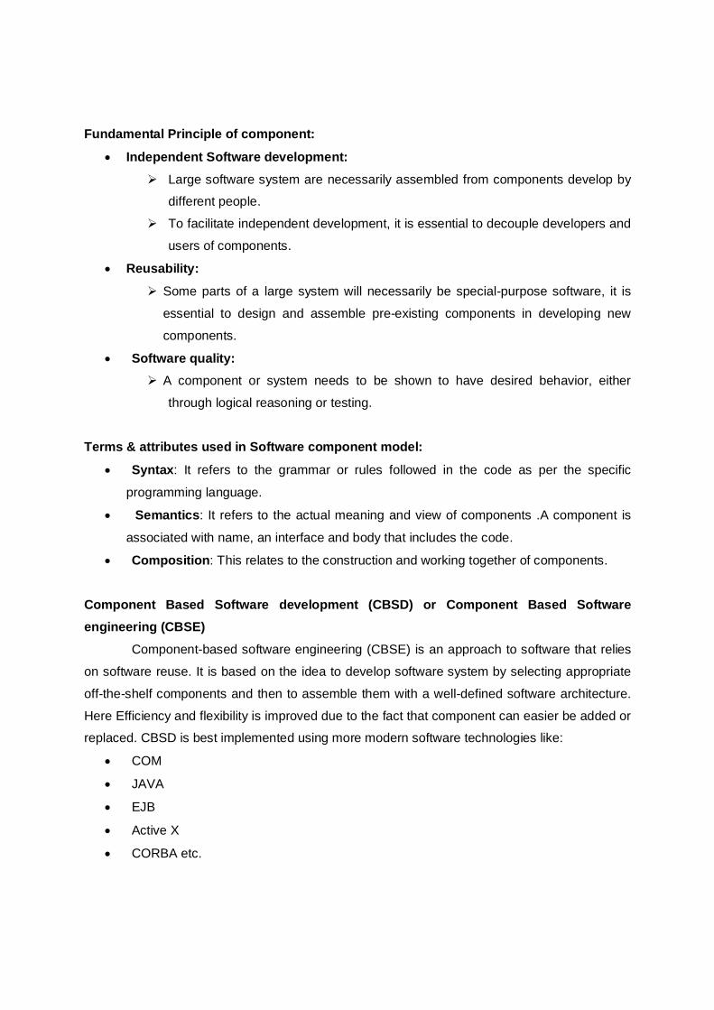
Note: CBSE vs Traditional software engineering 1. SE can fulfill requirements more easily. In CBSE requirements is based on available
components
2. CBSE life cycle is shorter than traditional SE
CBSE Waterfall
Find
Select
Requirement analysis
Design
Adapt
Test Deploy
Implementation
Test Replace
Replace Maintenance
3. CBSE is less expensive
1.4 SOFTWARE CHARECTERSTICS Now we are going to discuss about the different software characteristics that the good
software should have. While developing any kind of software product, the first question in developers mind is, “What are the characteristics that good software should have?”In a simple
way the answer is that good software must meet all the requirement of customer and the cost of
developing and maintaining the software is low.
But these are the obvious things which are expected from any software. If we observe
the technical characteristics of software then there are different characteristics. Following are
the different characteristics which can be easily explain with the help of software quality triangle
(Fig.1.1)
The three characteristics of good application software are:-
1) Operational Characteristics
2) Transition Characteristics 3) Revision Characteristics
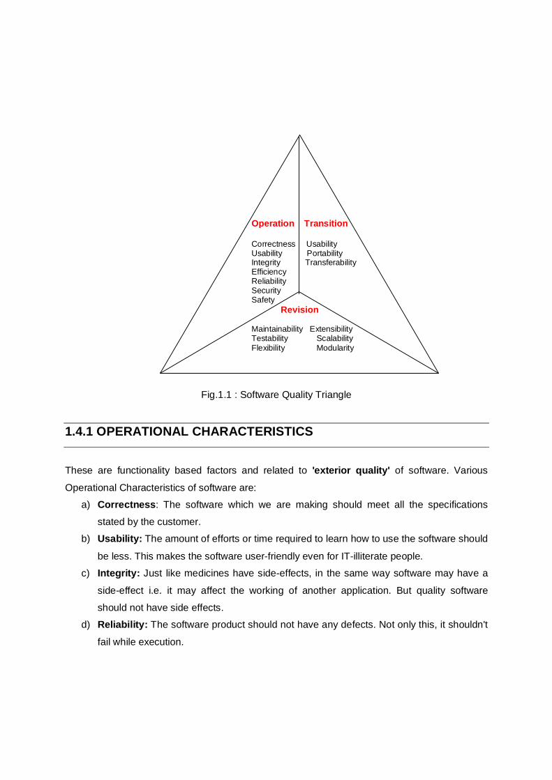
Fig.1.1: Software Quality Triangle
Fig.1.1 : Software Quality Triangle
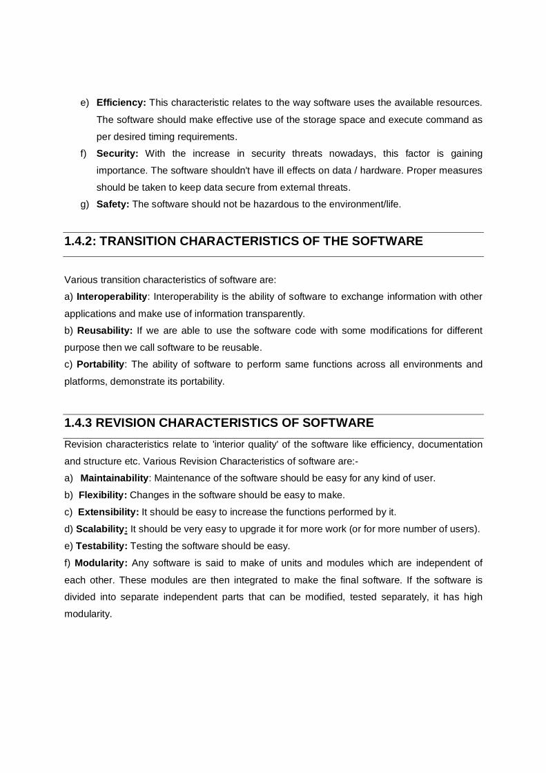
1.4.1 OPERATIONAL CHARACTERISTICS These are functionality based factors and related to 'exterior quality' of software. Various
Operational Characteristics of software are: a) Correctness: The software which we are making should meet all the specifications
stated by the customer. b) Usability: The amount of efforts or time required to learn how to use the software should
be less. This makes the software user-friendly even for IT-illiterate people. c) Integrity: Just like medicines have side-effects, in the same way software may have a
side-effect i.e. it may affect the working of another application. But quality software
should not have side effects. d) Reliability: The software product should not have any defects. Not only this, it shouldn't
fail while execution.
Operation Transition Correctness Usability Usability Portability Integrity Transferability Efficiency Reliability Security Safety Revision Maintainability Extensibility Testability Scalability Flexibility Modularity
e) Efficiency: This characteristic relates to the way software uses the available resources.
The software should make effective use of the storage space and execute command as
per desired timing requirements. f) Security: With the increase in security threats nowadays, this factor is gaining
importance. The software shouldn't have ill effects on data / hardware. Proper measures
should be taken to keep data secure from external threats. g) Safety: The software should not be hazardous to the environment/life.
1.4.2: TRANSITION CHARACTERISTICS OF THE SOFTWARE
Various transition characteristics of software are: a) Interoperability: Interoperability is the ability of software to exchange information with other
applications and make use of information transparently. b) Reusability: If we are able to use the software code with some modifications for different
purpose then we call software to be reusable. c) Portability: The ability of software to perform same functions across all environments and
platforms, demonstrate its portability.
1.4.3 REVISION CHARACTERISTICS OF SOFTWARE Revision characteristics relate to 'interior quality' of the software like efficiency, documentation
and structure etc. Various Revision Characteristics of software are:- a) Maintainability: Maintenance of the software should be easy for any kind of user.
b) Flexibility: Changes in the software should be easy to make.
c) Extensibility: It should be easy to increase the functions performed by it.
d) Scalability: It should be very easy to upgrade it for more work (or for more number of users).
e) Testability: Testing the software should be easy.
f) Modularity: Any software is said to make of units and modules which are independent of
each other. These modules are then integrated to make the final software. If the software is divided into separate independent parts that can be modified, tested separately, it has high
modularity.
1.5 SOFTWARE CRISIS Software crisis is a term which is used to describe
the rapid increase of software failure. A software project is
failed because of different reasons such as:-
Project running over budget
Project running overtime
Many software project produced software which did
not satisfy the requirement of the customer
Complexity of software project increase as hardware
capability increase.
Larger software system is more difficult and
expensive to maintain. SOFTWARE CRISIS CAN BE CLASSIFIED IN TWO WAYS
From Programmers point Of View.
From User point Of View
From programmers point of view:
1. PROBLEM OF COMPATIBILITY
2. PROBLEM OF PORTABILITY
3. PROBLEM OF DOCUMENTATION
4. PROBLEM OF PIRACY OF SOFTWARE
5. PROBLEM IN COORDINATION TO WORK WITH OTHER PEOPLE
6. PROBLEM THAT ARISE DURING ACTUAL RUN TIME IN THE ORGANIZATION 7. PROBLEM OF MAINTENANCE IN PROPER MANNER.
From user point of View:
1. HOW TO CHOOSE SOFTWARE FROM TOTAL MARKET AVAILABILITY
2. HOW TO ENSURE THAT WHICH SOFTWARE IS COMPATIBLE WITH THERE
HADRWARE.
3. PROBLEM OF VIRUSES.
4. PROBLEMS OF SOFTWARE BUGS.
5. CERTAIN SOFTWARE RUNS ON SPECIFIC OS.
6. PROBLEM OF DIFFERENT VERSIONS OF SOFTWARE.
7. ECURITY PROBLEM FOR PROTECTED DATA IN SOFTWARE
1.6 SOFTWARE ENGINEERING PROCESSES The term process means “a particular method of doing something, generally involving a number of steps or operations”. In Software engineering, the phrase software process refers to
the methods of developing software. The process that deals with the technical and management issues of software development is called software process. Many different types of activities
need to be performed to develop software. All these activities together comprise the software
process.
1.6.1 DESIRED CHARACTERISTICS OF A SOFTWARE PROCESS Let us discuss some of the important desirable characteristics of the software process:
Predictability: Predictability of a project determines how accurately the outcome of
process in a project can be predicted (About quality, cost estimation, LOC etc) before
the project is completed. Predictability can be considered a fundamental property of
any process.
Support testability and Maintainability: In software Engineering maintenance cost
generally exceed the development costs. Clearly, one of the objectives of the
development project should be to produce software that easy to maintain. And the
process used should ensure this maintainability. The Second importance about process is testing. Overall we can say that the goal of the process should not be to reduce the
effort of design and coding, but to reduce the cost of testing and maintenance. Both
testing and maintenance depend heavily on the quality of design and code, and this cost
can be considerably reduced if the software is designed and coded to make testing and
maintenance easier. Support change: Software change for a variety of reasons. Though changes were
always a part of life, change in today’s world is much faster. As organization a business
change, the software supporting the business has to change. Hence, any model that builds software and makes change very hard will not be suitable in many situations.
Early defect removal: Software development is actually going through some phases
(see 1.8). Error can occur at any phase during development. We should attempt to detect
errors that occur in phase during phase itself and should not wait until testing phase to detect errors. Error detection and correction should be a continuous process that is done
throughout software development.
Process improvement and Feedback: A process is not a static entity. Improving the
quality and reducing the cost of product are fundamental goal of any engineering discipline.
Process improvement is also an objective in a large project where feedback from early
parts of the project can be used to improve the execution of the rest of the project.
1.7 SOFTWARE QUALITY ATTRIBUTES
Like all engineering discipline, software engineering has also three major attributes:
Cost
Schedule
Quality
The cost of developing a system is the cost of the resources used for system. Which in the
case of software is determined by the manpower cost, as development is largely labor-intensive.
Hence, the cost of a software project is often measured in terms of person-month spent in a project.
Person-month: In software engineering Person-month is a measure of work effort. It can be
converted into dollar amount by multiplying it with average dollar cost.
Calculation:
If a project will take 2 months to finish with 3 people working full time on it, the project requires
2*3=6 person-month effort.
If an employee worked 20 days on a project, his contribution to the project is 1*20/30 = 0.6666
person-month. (Note that month is considered 30 days in such calculations.)
Schedule is also an important factor in software projects. Business trends are dictating
that the time to market of a product should be reduced; i.e. the cycle time from concept to
delivery should be small. For software this means that it needs to be developed faster.
The other major attribute of any production discipline is quality. Today, quality is the
main thing. So, clearly developing high quality Software is another fundamental goal of software
Software Quality
Functionality
Reliability
Usability
Efficiency
Maintainability
Portability
engineering. However the concept of quality in the context of software needs further discussion.
We use the international standard on software product quality as the basis of our discussion
here. According to the quality model adopted by this standard, software quality comprise of six
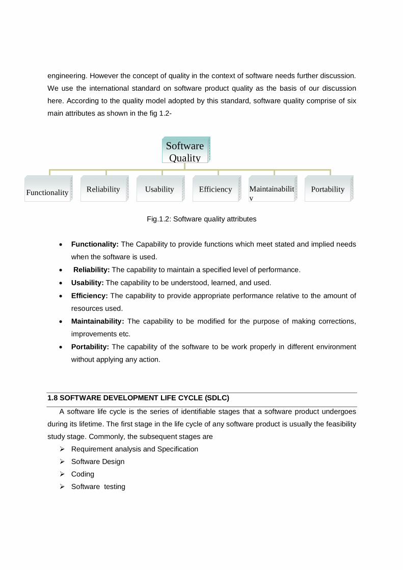
main attributes as shown in the fig 1.2-
Fig.1.2: Software quality attributes
Functionality: The Capability to provide functions which meet stated and implied needs
when the software is used.
Reliability: The capability to maintain a specified level of performance.
Usability: The capability to be understood, learned, and used.
Efficiency: The capability to provide appropriate performance relative to the amount of
resources used.
Maintainability: The capability to be modified for the purpose of making corrections,
improvements etc.
Portability: The capability of the software to be work properly in different environment
without applying any action.
1.8 SOFTWARE DEVELOPMENT LIFE CYCLE (SDLC)
A software life cycle is the series of identifiable stages that a software product undergoes
during its lifetime. The first stage in the life cycle of any software product is usually the feasibility
study stage. Commonly, the subsequent stages are
Requirement analysis and Specification
Software Design
Coding
Software testing
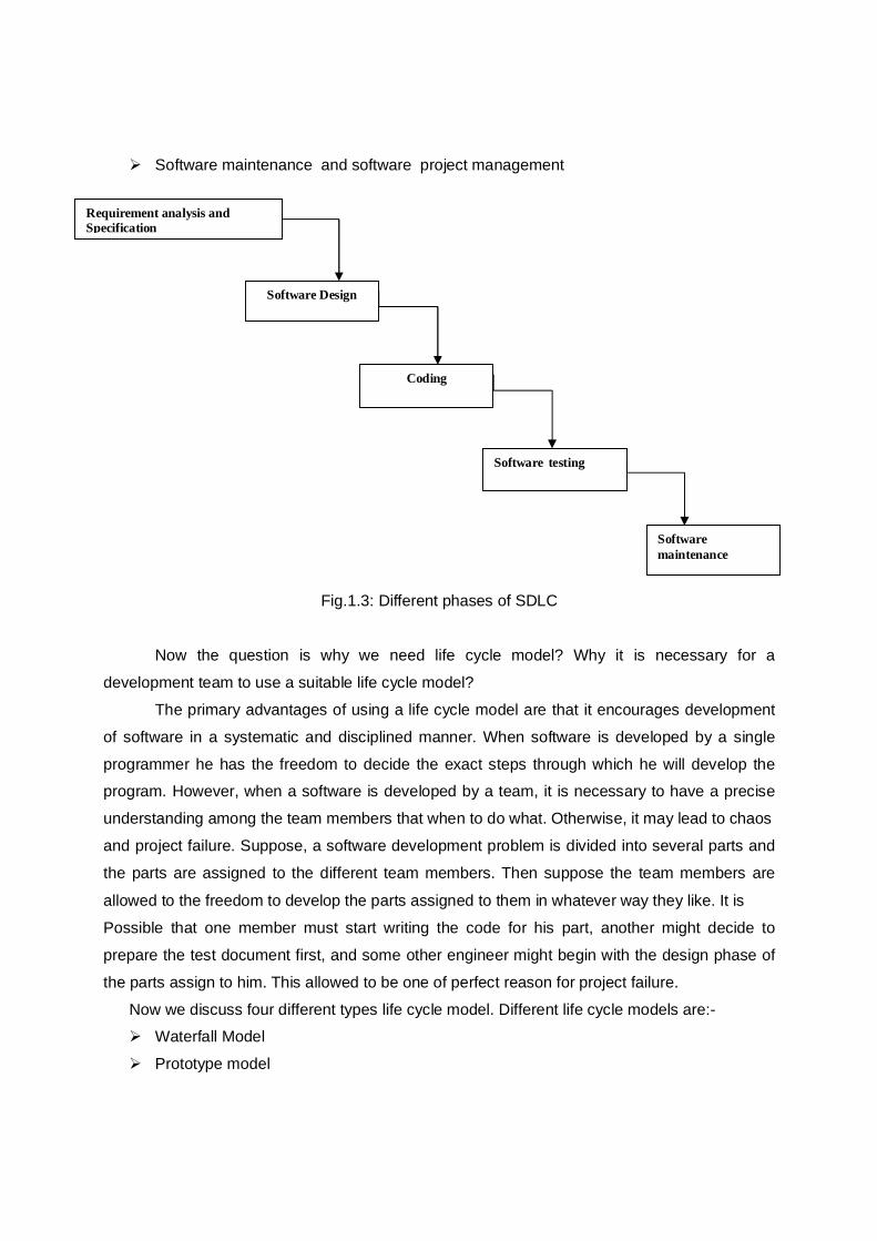
Software maintenance and software project management
Fig.1.3: Different phases of SDLC
Now the question is why we need life cycle model? Why it is necessary for a
development team to use a suitable life cycle model?
The primary advantages of using a life cycle model are that it encourages development
of software in a systematic and disciplined manner. When software is developed by a single
programmer he has the freedom to decide the exact steps through which he will develop the program. However, when a software is developed by a team, it is necessary to have a precise
understanding among the team members that when to do what. Otherwise, it may lead to chaos
and project failure. Suppose, a software development problem is divided into several parts and
the parts are assigned to the different team members. Then suppose the team members are
allowed to the freedom to develop the parts assigned to them in whatever way they like. It is
Possible that one member must start writing the code for his part, another might decide to
prepare the test document first, and some other engineer might begin with the design phase of
the parts assign to him. This allowed to be one of perfect reason for project failure.
Now we discuss four different types life cycle model. Different life cycle models are:- Waterfall Model
Prototype model
Requirement analysis and Specification
Software Design
Coding
Software testing
Software maintenance
Evolutionary Development Model
Spiral Model
1.8.1 WATERFALL MODEL The waterfall model is intuitively the most obvious way to develop software. It was the
first process model to be introduced. It is very simple to understand and use. In a waterfall
model, each phase must be completed fully before the next phase can begin. At the end of each
phase, a review takes place to determine if the project is on the right path and whether or not to
continue or discard the project.
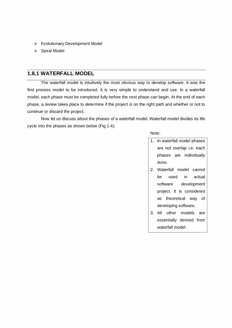
Now let us discuss about the phases of a waterfall model. Waterfall model divides its life
cycle into the phases as shown below (Fig 1.4):
Note:
1. In waterfall model phases
are not overlap i.e. each
phases are individually
done.
2. Waterfall model cannot
be used in actual
software development
project. It is considered
as theoretical way of
developing software.
3. All other models are
essentially derived from
waterfall model.
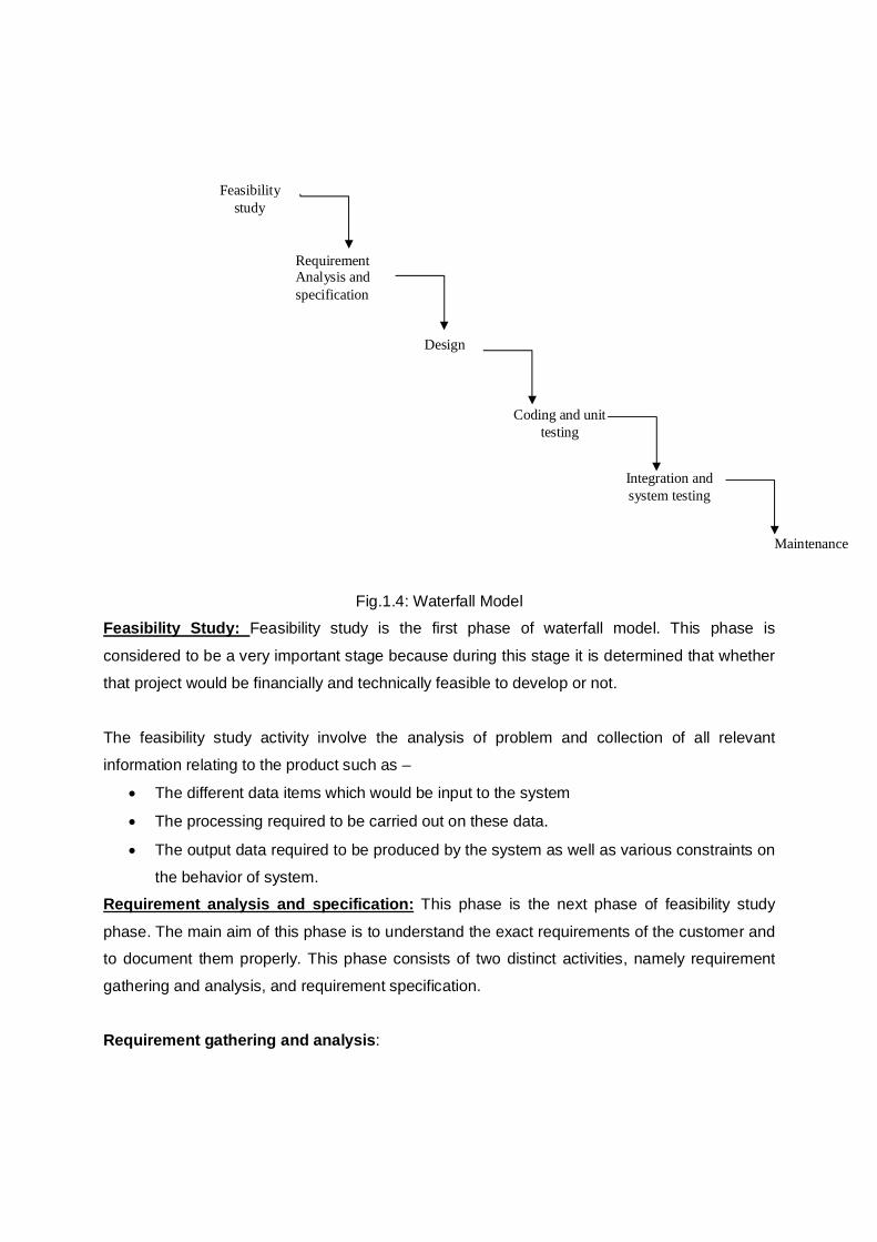
Fig.1.4: Waterfall Model Feasibility Study: Feasibility study is the first phase of waterfall model. This phase is
considered to be a very important stage because during this stage it is determined that whether
that project would be financially and technically feasible to develop or not.
The feasibility study activity involve the analysis of problem and collection of all relevant
information relating to the product such as –
The different data items which would be input to the system
The processing required to be carried out on these data.
The output data required to be produced by the system as well as various constraints on
the behavior of system. Requirement analysis and specification: This phase is the next phase of feasibility study
phase. The main aim of this phase is to understand the exact requirements of the customer and to document them properly. This phase consists of two distinct activities, namely requirement
gathering and analysis, and requirement specification.
Requirement gathering and analysis:
Coding and unit testing
Integration and system testing
Design
Maintenance
Feasibility study
Requirement Analysis and specification
The goal of the requirement gathering activity is to collect all relevant information from
the customer regarding the product to be developed. The data collected from the customer
usually contain several contradictions and ambiguities. So, it is necessary to identify all
ambiguities and contradiction in the requirement and resolve them through further discussion with the customer. After all ambiguities, inconsistencies and incompleteness have been
removed and all the requirement properly understood, the requirement specification activity can
start. During this activity, the user requirement is systematically organize into a software
requirement specification document (SRS). Requirement specification: After identifying customer requirement during the requirement gathering and analysis
activity it is written into a document called SRS (software requirement specification).The
important component of a SRS are the functional requirement, non functional requirement and
goal of implementation. Functional requirement means the identification of the functions to be supported by the system. Each function can be characterized by input data, the processing
required on input data, the output data to be produced. The non-functional requirement
identifies the performance requirements, the standards to be followed etc. The SRS document
is written using the end user terminology. This makes the SRS document understandable by the
customer. The SRS document normally serves as a contract between the development team
and customer. Any future dispute between the customer and the development team can be
settled by examining the SRS document not only provide the basic for carrying out all the
development activities, but also the basis for several other documents such as design
document, the users manuals, the system test plan etc. Design: After successful completion of requirement analysis phase design phase start. The
goal of design phase is to transform the requirement specified in the SRS document into a
structure that is suitable for implementation in some programming language. We say that in
design phase the software architecture is derived from SRS document. Coding and Unit Testing: The purpose of the coding and unit testing phase of software
development is to translate the software design into source code. Each component of the
design is implemented as a program module. The end-product of this phase is a set of program
modules that have been individually tested.
During this phase, each module is unit tested to determine the correct working of all the individual modules. Integration and System testing: Integration of different module is started once they have been
coded and unit tested. During the integration and system testing phase, the module is integrated
in a planned manner. Integration is normally carried out incrementally over a number of steps.
During each integration step, the partially integrated system is tested and a set of previously
planned module are added to it. Finally, when the entire module have been successfully
integrated and tested, system testing is carried out. System testing usually consists of three
different kind of testing activities: α-testing: It is the system testing perform by development team. β-testing:It is the system testing performed by friendly set of customers.
Acceptance testing: It is the system testing performed by the customer himself after the
product delivery to determine whether to accept or reject the delivered product.
System testing is normally carried out in a planned manner according to the system test
plan document. The system test plan identifies all testing-related activities that must be
performed, specifies the scheduled of testing, allocate resources. It also lists all the test cases
and the expected output for each test case. A system test plan can be prepared immediately
after the requirement specification phase, which documents the plan for system testing. It is
possible to prepare the system test plan just after the requirements phase, solely based on SRS
document. The result of integration and system testing are documented in the form of test report. The test report summarizes the outcome of all the testing activities that were carried out
during this phase. Maintenance: Maintenance of a typical software product requires much effort than the effort
necessary to develop the product itself. Maintenance involves performing any one or more of
the following kind of activities:
Corrective maintenance: Correcting error that was not discovered during the product
development phase. This is called Corrective maintenance.
Perfective maintence: Improving the implementation of the system and enhancing the
functionalities of the system according to the customer’s requirements.
Adaptive maintenance: Porting the software to work in a new environment (ex: to work
on different operating system).
Advantages of waterfall model:
Simple and easy to understand and use.
Easy to manage due to the rigidity of the model – each phase has specific deliverables
and a review process.
Phases are processed and completed one at a time.
Works well for smaller projects where requirements are very well understood.
Disadvantages of waterfall model:
Once an application is in the testing stage, it is very difficult to go back and change
something that was not well-thought out in the concept stage.
No working software is produced until late during the life cycle.
High amounts of risk and uncertainty.
Not a good model for complex and object-oriented projects.
Poor model for long and ongoing projects.
Not suitable for the projects where requirements are at a moderate to high risk of
changing.
When to use the waterfall model:
Requirements are very well known, clear and fixed.
Product definition is stable.
Technology is understood.
There are no ambiguous requirements
Ample resources with required expertise are available freely
The project is short.
1.8.2 PROTOTYPING MODEL Let us discus another model which name is prototyping model. The basic idea here is
that instead of freezing the requirements before any design or coding can proceed, a throwaway
prototype is built to help understand the requirements. This prototype is developed based on the
currently known requirements. Development of the prototype obviously undergoes design,
coding, and testing, but each of these phases is not done very formally or thoroughly. After
making this prototype it is submitted to the customer for evaluation. Based on the customer
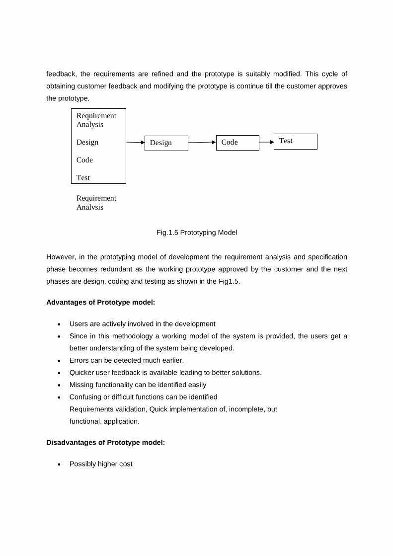
feedback, the requirements are refined and the prototype is suitably modified. This cycle of
obtaining customer feedback and modifying the prototype is continue till the customer approves
the prototype.
Fig.1.5 Prototyping Model However, in the prototyping model of development the requirement analysis and specification
phase becomes redundant as the working prototype approved by the customer and the next
phases are design, coding and testing as shown in the Fig1.5.
Advantages of Prototype model:
Users are actively involved in the development
Since in this methodology a working model of the system is provided, the users get a better understanding of the system being developed.
Errors can be detected much earlier.
Quicker user feedback is available leading to better solutions.
Missing functionality can be identified easily
Confusing or difficult functions can be identified
Requirements validation, Quick implementation of, incomplete, but
functional, application.
Disadvantages of Prototype model:
Possibly higher cost
Design
Code
Test
Requirement Analysis Design Code Test
Requirement Analysis
Practically, this methodology may increase the complexity of the system as scope of the
system may expand beyond original plans.
Incomplete application may cause application not to be used as the
full system was designed Incomplete or inadequate problem analysis.
When to use Prototyping model:
Prototype model should be used when the desired system needs to have a lot of
interaction with the end users.
Typically, online systems, web interfaces have a very high amount of interaction with
end users, are best suited for Prototype model. It might take a while for a system to be
built that allows ease of use and needs minimal training for the end user.
Prototyping ensures that the end users constantly work with the system and provide a
feedback which is incorporated in the prototype to result in a useable system. They are excellent for designing good human computer interface systems.
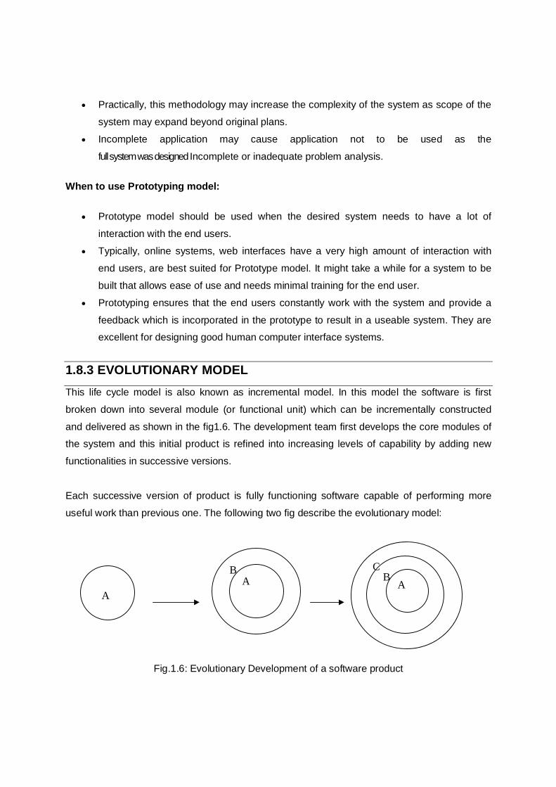
1.8.3 EVOLUTIONARY MODEL This life cycle model is also known as incremental model. In this model the software is first
broken down into several module (or functional unit) which can be incrementally constructed
and delivered as shown in the fig1.6. The development team first develops the core modules of the system and this initial product is refined into increasing levels of capability by adding new
functionalities in successive versions.
Each successive version of product is fully functioning software capable of performing more
useful work than previous one. The following two fig describe the evolutionary model:
Fig.1.6: Evolutionary Development of a software product
A B
A
A B
C
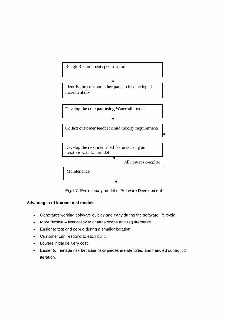
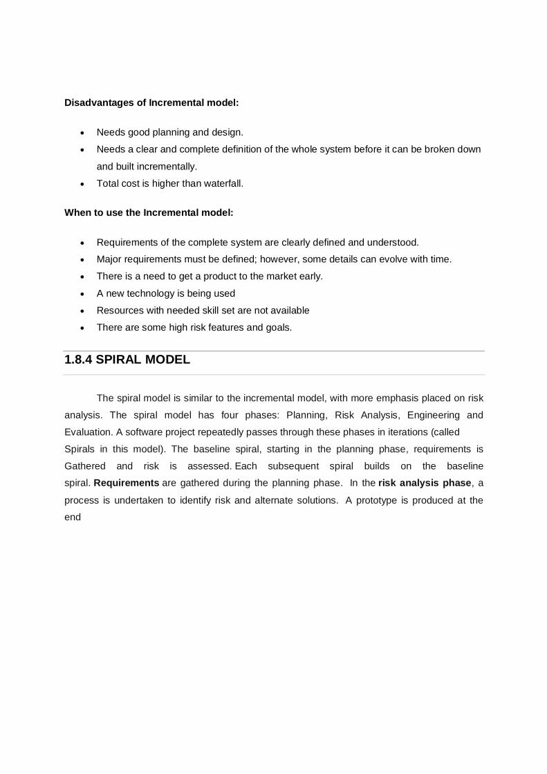
Fig.1.7: Evolutionary model of Software Development
Advantages of Incremental model:
Generates working software quickly and early during the software life cycle.
More flexible – less costly to change scope and requirements.
Easier to test and debug during a smaller iteration.
Customer can respond to each built.
Lowers initial delivery cost.
Easier to manage risk because risky pieces are identified and handled during it’d
iteration.
Rough Requirement specification
Maintenance
Develop the next identified features using an iterative waterfall model
Identify the core and other parts to be developed incrementally
Develop the core part using Waterfall model
Collect customer feedback and modify requirements
All Features complete
Disadvantages of Incremental model:
Needs good planning and design.
Needs a clear and complete definition of the whole system before it can be broken down
and built incrementally.
Total cost is higher than waterfall.
When to use the Incremental model:
Requirements of the complete system are clearly defined and understood. Major requirements must be defined; however, some details can evolve with time.
There is a need to get a product to the market early.
A new technology is being used
Resources with needed skill set are not available
There are some high risk features and goals.
1.8.4 SPIRAL MODEL
The spiral model is similar to the incremental model, with more emphasis placed on risk
analysis. The spiral model has four phases: Planning, Risk Analysis, Engineering and
Evaluation. A software project repeatedly passes through these phases in iterations (called
Spirals in this model). The baseline spiral, starting in the planning phase, requirements is
Gathered and risk is assessed. Each subsequent spiral builds on the baseline spiral. Requirements are gathered during the planning phase. In the risk analysis phase, a
process is undertaken to identify risk and alternate solutions. A prototype is produced at the end
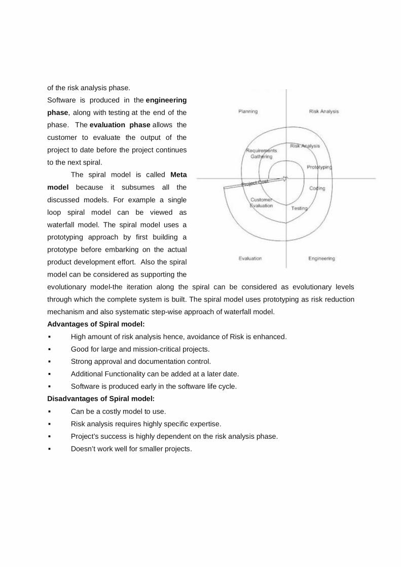
of the risk analysis phase. Software is produced in the engineering phase, along with testing at the end of the phase. The evaluation phase allows the
customer to evaluate the output of the
project to date before the project continues
to the next spiral. The spiral model is called Meta
model because it subsumes all the
discussed models. For example a single
loop spiral model can be viewed as
waterfall model. The spiral model uses a prototyping approach by first building a
prototype before embarking on the actual
product development effort. Also the spiral
model can be considered as supporting the
evolutionary model-the iteration along the spiral can be considered as evolutionary levels
through which the complete system is built. The spiral model uses prototyping as risk reduction
mechanism and also systematic step-wise approach of waterfall model. Advantages of Spiral model: High amount of risk analysis hence, avoidance of Risk is enhanced.
Good for large and mission-critical projects. Strong approval and documentation control.
Additional Functionality can be added at a later date.
Software is produced early in the software life cycle. Disadvantages of Spiral model: Can be a costly model to use.
Risk analysis requires highly specific expertise.
Project’s success is highly dependent on the risk analysis phase.
Doesn’t work well for smaller projects.
When to use Spiral model: When costs and risk evaluation is important
For medium to high-risk projects Long-term project commitment unwise because of potential changes to economic
priorities
Users are unsure of their needs
Requirements are complex
New product line
Significant changes are expected (research and exploration
CHECK YOUR PROGRESS
1. Reusability is ________ type of characteristics
2. Person month is measure of ____________ in software engineering.
3. Software crisis means ________________
4. Cost, schedule and quality are software ___________ 5. Which of the following is not an type of software quality attribute
a) Efficiency b) Scalability c) Dependability d) Usability
6. ___________determines whether the project should go forward
A. Feasibility study
B. System evaluation
C. Design
D. None of these
7. SRS stands for-
1. Software requirement
solution
2. Software requirement specification
3. System requirement
specification
4. None of these
8. Requirement can be refine using
B. Waterfall Model
C. Evaluation Model
D. Prototyping Model
E. None of these
9. Software feasibly is based on which of the following
A. Business and marketing
concern
B. Scope, constraints, market
C. Technology, finance, time,
resources
D. Technical power of developer
10. Which of the following model is called Meta Model B. Prototyping
C. Spiral
D. Waterfall
E. Evolutionary
1.9 LET US SUM UP
Software engineering is the discipline that aims to provide methods and procedures for
systematically developing industrial strength software. Software engineering uses
systematic approaches, methods, tools and procedure to solve a problem.
Software components are independent software unit that can be composed with other
components to create a full software system.
The term component-based software Development (CBSD) or component-based
software Engineering (CBSE) can be refereed as a process for building a system using
components. Here reliability is increased since components have previously been tested
in various contexts.
The three characteristics of good application software are:-
1) Operational Characteristics
2) Transition Characteristics 3) Revision Characteristics
Software crisis (Software Failure) refers to the difficulty of writing correct,
understandable, and verifiable computer programs. The roots of the software crisis are
complexity, expectations, and change. The crisis manifested itself in several ways:
Projects running over-budget, Projects running over-time, Software was very inefficient
etc.
In Software engineering, the phrase software process refers to the methods of
developing software.
Like all engineering discipline, software engineering has also three major attributes:
Cost, Schedule and Quality.
A software life cycle is the series of identifiable stages that a software product
undergoes during its lifetime. The first stage in the life cycle of any software product is usually the feasibility study stage. Commonly, the subsequent stages are Requirement
analysis and Specification, Software Design, Coding, Software testing, Software
maintenance.
Name of different life cycle models are Waterfall Model, Prototype model, Evolutionary,
Development Model, Spiral Model.
1.10 ANSWERS TO CHECK YOUR PROGRESS
1. Transition
2.Work Effort
3.Software Failure
4.Attribute
5.c)Dependability 6. A. Feasibly study
7. C. Software requirement specification 8. C. Prototyping model
9. C .Technology, finance, time, recourses
10.B. Spiral
1.11 FURTHER READINGS
1. An Integrated Approach to Software engineering—Pankaj Jalote
2. Software Engineering—Rajib Mall
MODEL QUESTIONS 1. What do you mean by Software Engineering? Why we need software engineering
techniques?
2. What do you mean by software components? How CBSE is different from traditional
software engineering?
3. Define the characteristics of good software?
4. Explain the term software crisis?
5. What do you mean by the term person-month? Explain the software quality model?
6. Why we need SDLC model? 7. What are the different life cycle models? Explain Waterfall model? Write down the
advantages and disadvantages of waterfall model?
8. Explain the prototyping model with their advantages and disadvantages?
9. Explain the spiral model of software engineering with their advantages? Why it is called
Meta model?
10. Write down the concept of evolutionary Development model?
11. Explain Iterative Enhancement Model of software development?
12. Compare all the life cycle models with their advantage and disadvantages?
******
UNIT- 2 SOFTWARE REQUIREMENT SPECIFICATIONS (SRS) UNIT STRUCTURE
2.1 Learning Objectives 2.2 Introduction
2.3 Requirement Engineering Process
2.3.1 Elicitation
2.3.2 Analysis
2.3.3 Documentation
2.3.4 Review and Management of User Needs
2.4 Feasibility Study
2.5 Information Modeling
2.6 Data Flow Diagrams
2.7 Entity Relationship Diagrams 2.8 Decision Tables
2.9 SRS Document
2.10 IEEE Standards for SRS
2.11 Software Quality Assurance (SQA)
2.11.1 Verification and Validation
2.11.2 SQA Plans
2.12 ISO 9000 Models
2.13 SEI-CMM Model
2.14Let Us Sum Up 2.15Further Readings
2.16 Answers To Check Your Progress
2.17 Possible Questions
2.1 LEARNING OBJECTIVES
After going through this unit, you will be able to:
• Know about the requirement engineering process of software development
• Describe feasibility study and why it needs to be done.
• Learn about Data Flow Diagrams and Entity Relationship Diagrams
• Know about what is SRS Document and the IEEE Standards
2.3 Requirement Engineering Process The requirement engineering is an important aspect of software engineering. The software development life cycle starts with requirements analysis. A requirement is a description of what
the system should perform in order to solve the problem faced by the users in an organization. It is more specific than a need. Requirements Engineering is the process of establishing the
services that the customer requires from the system and the constraints under which it is to be
developed and operated. Requirement engineering is considered to be the most important stage
in designing and developing software as it addresses the critical problem of developing the right
software for the customer. It is a set of processes by which the requirements for a software
project are collected, documented and managed throughout the software development life cycle.
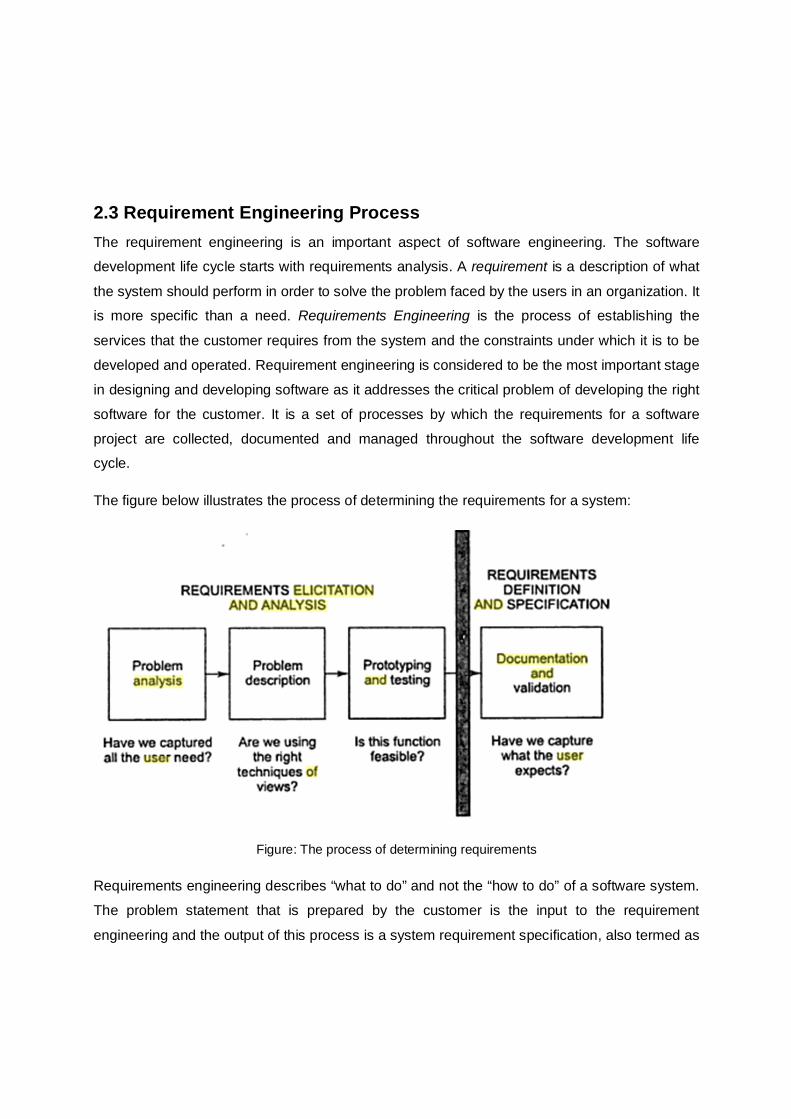
The figure below illustrates the process of determining the requirements for a system:
Figure: The process of determining requirements
Requirements engineering describes “what to do” and not the “how to do” of a software system.
The problem statement that is prepared by the customer is the input to the requirement
engineering and the output of this process is a system requirement specification, also termed as
Requirement Definition and description (RDD). This RDD then forms the basis for designing the software solutions.
Requirements can be categorized based on their priority and functionality. Based on priority they are of three types.
Those that has to met absolutely,
Those that are desirable but not necessary,
Those that are possible but could also be eliminated. Again based on their functionality, the requirements are of two different types.
Functional Requirements defines what type of functionality the system to be developed
offers. Usually these are again divided into functional requirements, behavioral
requirements and data requirements.
Non-functional Requirements defines the desired qualities of the system to be
developed like usability, efficiency, performance, reliability etc. They affect the system
more than the functional requirements. The non-functional requirements are also known
as the quality requirements. Apart from these there is another type of requirement called Constraints. Although they are not
implemented as the other types of requirements but they limit the solution space that is available during the development process.
The requirement engineering processes can be described by considering three fundamental concerns:
Understanding the problem (‘what the problem is’)
Formally describing the problem,
Attaining an agreement on the nature of the problem. Each of the above mentioned concerns implies that there must be some activities corresponding to each of these. The requirement engineering thus consists of the following processes:
1. Requirements gathering (Elicitation),
2. Requirements Analysis,
3. Requirements Documentation,
4. Requirements Review,
5. Requirements Management. The different steps are shown in the figure below.
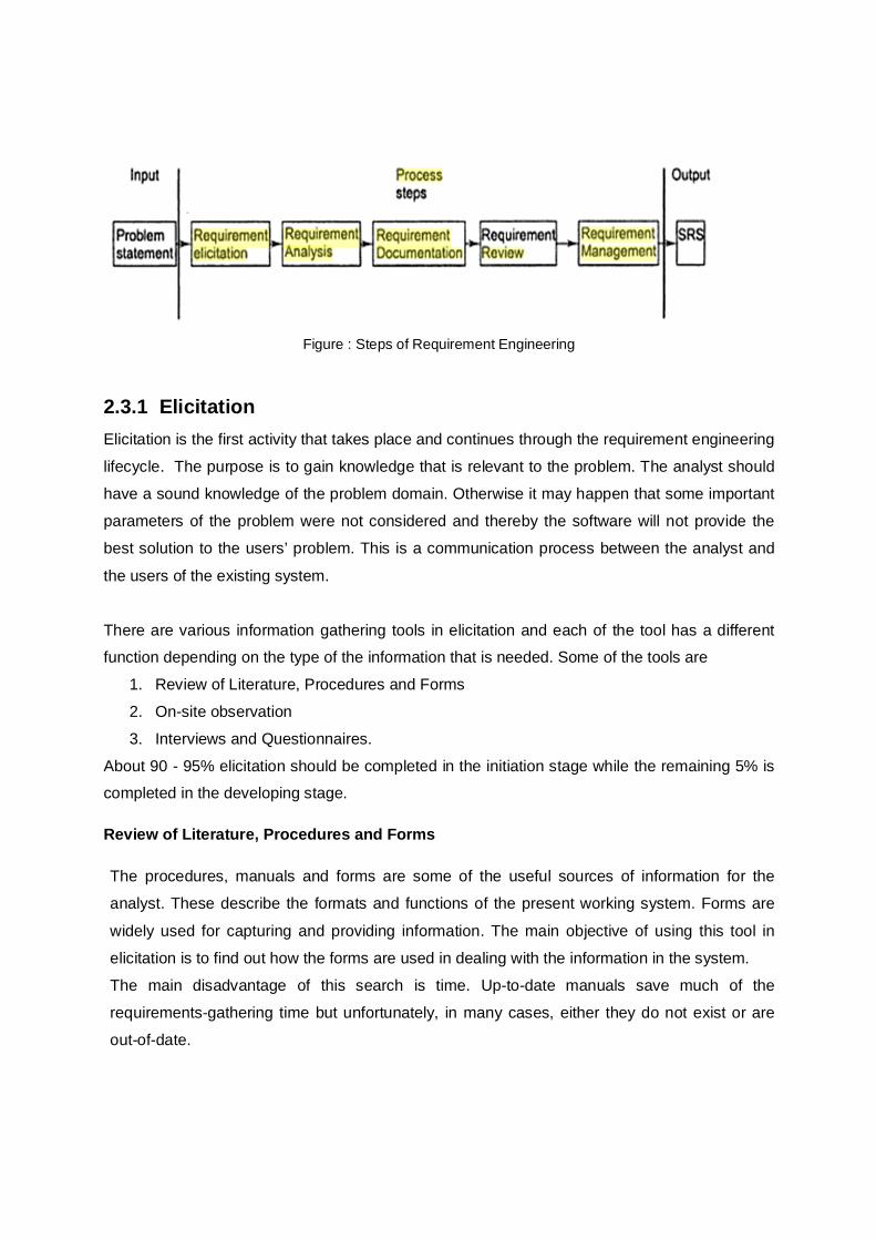
Figure : Steps of Requirement Engineering
2.3.1 Elicitation Elicitation is the first activity that takes place and continues through the requirement engineering
lifecycle. The purpose is to gain knowledge that is relevant to the problem. The analyst should
have a sound knowledge of the problem domain. Otherwise it may happen that some important
parameters of the problem were not considered and thereby the software will not provide the
best solution to the users’ problem. This is a communication process between the analyst and
the users of the existing system.
There are various information gathering tools in elicitation and each of the tool has a different function depending on the type of the information that is needed. Some of the tools are
1. Review of Literature, Procedures and Forms
2. On-site observation
3. Interviews and Questionnaires.
About 90 - 95% elicitation should be completed in the initiation stage while the remaining 5% is completed in the developing stage.
Review of Literature, Procedures and Forms
The procedures, manuals and forms are some of the useful sources of information for the
analyst. These describe the formats and functions of the present working system. Forms are
widely used for capturing and providing information. The main objective of using this tool in
elicitation is to find out how the forms are used in dealing with the information in the system.
The main disadvantage of this search is time. Up-to-date manuals save much of the
requirements-gathering time but unfortunately, in many cases, either they do not exist or are
out-of-date.
On-site observation
It is an observational technique that can be used to understand social and organizational
requirements. The advantage of this technique is that the analyst can get a close picture of the system being studied. The analyst observes the day-to-day work and makes a note of the work
performed. What the system is and what it does, who are the people that are running the
system and so on are some of the questions that can be answered by using the on-site
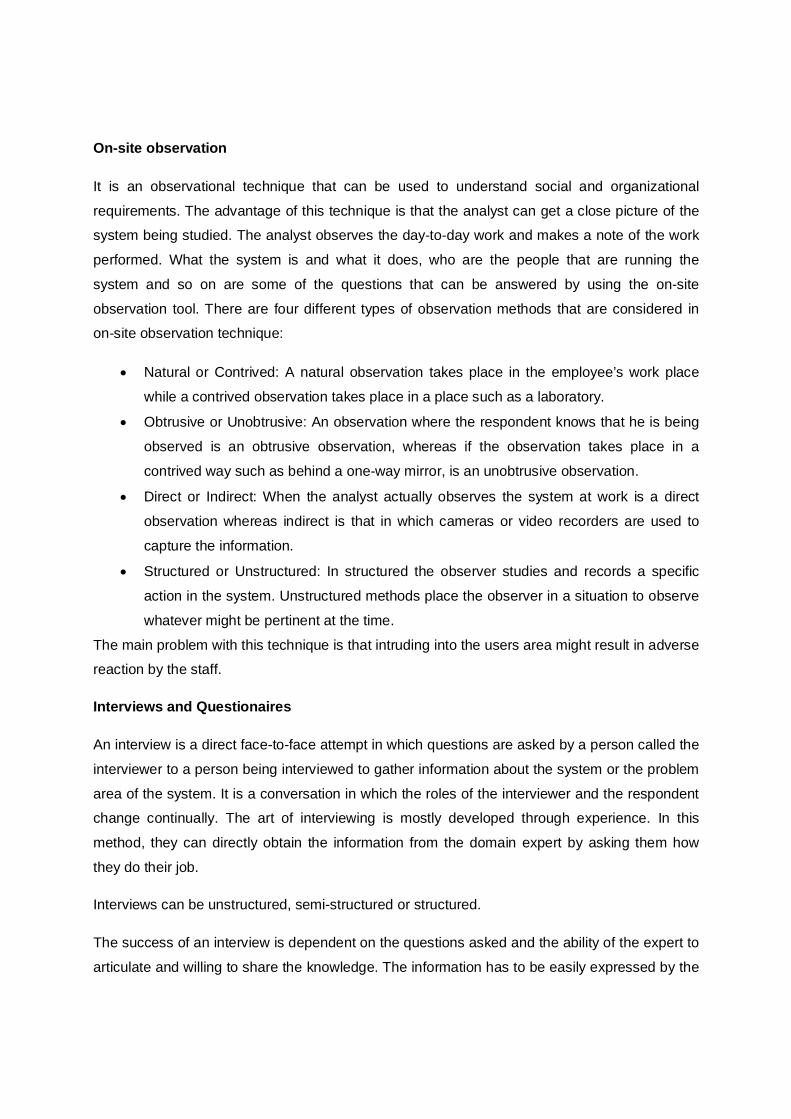
observation tool. There are four different types of observation methods that are considered in on-site observation technique:
Natural or Contrived: A natural observation takes place in the employee’s work place
while a contrived observation takes place in a place such as a laboratory.
Obtrusive or Unobtrusive: An observation where the respondent knows that he is being
observed is an obtrusive observation, whereas if the observation takes place in a
contrived way such as behind a one-way mirror, is an unobtrusive observation.
Direct or Indirect: When the analyst actually observes the system at work is a direct
observation whereas indirect is that in which cameras or video recorders are used to
capture the information.
Structured or Unstructured: In structured the observer studies and records a specific
action in the system. Unstructured methods place the observer in a situation to observe
whatever might be pertinent at the time.
The main problem with this technique is that intruding into the users area might result in adverse reaction by the staff.
Interviews and Questionaires
An interview is a direct face-to-face attempt in which questions are asked by a person called the
interviewer to a person being interviewed to gather information about the system or the problem
area of the system. It is a conversation in which the roles of the interviewer and the respondent change continually. The art of interviewing is mostly developed through experience. In this
method, they can directly obtain the information from the domain expert by asking them how
they do their job.
Interviews can be unstructured, semi-structured or structured.
The success of an interview is dependent on the questions asked and the ability of the expert to
articulate and willing to share the knowledge. The information has to be easily expressed by the
expert, which is often difficult when tasks that are frequently performed often become
‘automatic’. Indirect methods are then used to obtain the information that otherwise cannot be expressed directly.
Another tool used is the questionnaire. It consists of a series of questions to which the
individuals responds. It is self administered and is much economical than interview. A
questionnaire can be given to a large number of the system users at the same time. Questions in a questionnaire can be open-ended or closed ended.
2.3.2 ANALYSIS The next step after elicitation is requirement analysis. After gathering the requirements in the
elicitation stage, each of them is then analyzed to get a clear picture of the exact customer
requirements and also the product to be developed. This is done by checking the validity,
consistency and feasibility of the gathered requirements. The validity checks and confirms its
relevance to goals and objectives, consistency confirms that the requirements does not conflict
with the other requirements and then feasibility ensures that the inputs and the required technology support is available for the project development.
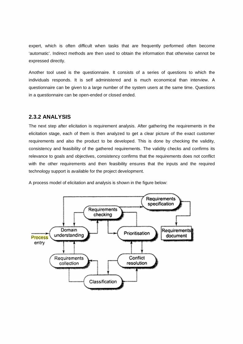
A process model of elicitation and analysis is shown in the figure below:
This is a general model and each organization will have its different versions depending on many factors of it like the staff, the type of the proposed system, standards used etc.
In Domain understanding, the analyst must properly understand the domain for which a system
has to be developed. After that the requirements of the stakeholders of the organization must be gathered. The requirements should be organized accordingly in classification. There are again
chances for requirements conflict in the organization as different stakeholders have different
types of requirements. Basically there are three types of requirements that the analyst needs to identify and resolve in conflict resolution. They are ambiguity, inconsistency and
incompleteness. Anomaly is an ambiguity in the requirement. If there is anomalous requirement,
then several interpretation of that requirement is possible which may lead to finally an incorrect
system. Requirements can be incomplete if some of them has been overlooked by the stake
holders. The analyst can suggest those requirements to the users for their consideration and approval to incorporate those in the requirements lists. Conflict resolution requires effort and experience of the analyst to detect them.
In prioritization, the requirements are to be given priority based on their importance. Finally in
the requirements checking, the requirements are checked to discover if they are complete, consistent and in accordance with what is actually wanted from the system.
2.3.3 DOCUMENTATION
After gathering the required information needed to develop the new system and analyzing each
of them by removing the anomalies, inconsistencies and incompleteness, the analyst organizes
the requirements in a proper format in the form of an SRS (Software Requirement Specification) document. The SRS document usually contains all the users’ requirements. It also serves as a
contract document between the customer and the developer.
2.3.4 REVIEW AND MANAGEMENT OF USER NEEDS A requirement review is a manual process of evaluation or examination of the requirements
documents. It involves people from both the client and contractor organization so as to check
the documents for anomalies and omissions. Requirements review can be informal or formal. These techniques are used to examine the requirements before developing the new system.
1. Informal review: In this type of reviews, the contractor meets as many stakeholders as
possible and discusses the requirements. This type of meeting is not structured and the
meeting time is not prepared and distributed. Some problems can be detected by simply
talking about the system to the stakeholders before a formal review.
2. Formal review: In formal review, the meetings and schedules are properly planned. The
development team makes the client understand the system requirements and the
implications of each of the requirements. The review team checks each of the
requirement for consistency and completeness. Any conflicts, contradictions, errors and omissions in the requirements should be pointed out by the review team and formally recorded in the review report.
CHECK YOUR PROGRESS 1 1. Fill in the blanks:
a. The process of establishing the services that the customer requires from the system and the constraints under which it is to be developed and operated is called
_____________________________.
b. The input to requirement engineering is _________________ and the output of this
process is a ______________________.
c. Based on priority, requirements are of _____________________ types.
d. Requirements are of two different types based on their functionality
_______________________ and ______________________.
e. Elicitation is a communication process between the ________________and the
_______________ of the existing system. f. An _________________ is a direct face-to-face attempt in which questions are asked by
a person to another person.
g. Interviews may be__________, ________________ or__________________.
h. In________________________, the analyst must properly understand the domain for
which a system has to be developed.
i. The three types of requirements that the analyst needs to resolve in conflict resolution
are_____________, _________________ and________________.
j. ______________ serves as a contract document between the customer and the
developer.
2.4 FEASIBILITY STUDY
In case the system proposal is accepted by the management after the review of the users’
requirements, the next step is to examine the feasibility of the system. A feasibility study is
carried out to identify, describe and evaluate the candidate systems and select the best system
that meets performance requirements. A proper feasibility study will show the strengths and
deficits before the project is planned or budgeted for. By doing the research beforehand,
companies can save money and resources in the long run by avoiding projects that are not feasible.
It is basically the test of the proposed system in the light of its workability, meeting user’s
requirements, effective use of resources and of course, the cost effectiveness. These are
categorized as economic, technical and operational feasibility. Economic feasibility: This is more commonly known as the cost/benefit analysis. The benefits
and savings that are expected from the candidate system is determined and then compared
with the cost. If benefits outweigh costs, then the decision is made to design and implement the
system. Technical feasibility: The technical requirements of the proposed project are considered in
technical feasibility. It studies whether the problem can be solved using existing technology and
available resources. The technical requirements of the proposed system are compared to the
technical capability of the organization. The systems project is considered technically feasible if
the internal technical capability is sufficient to support the project requirements. The analyst
must also find out to whether the existing resources can be upgraded to fulfill the request under
consideration.
Operational feasibility: It examines the users’ and the management’s acceptance and support
for the new system. It is also known as behavioral feasibility because it measures the behavior
of the users. If the users do not accept the new technology or system then it will definitely fail to
serve the purpose of developing the software product. One of the common method of obtaining
user acceptance and support is through user involvement by communicating, educating and
involving them. Thus the introduction of a candidate system requires effort to educate and train
the staff on new ways of conducting business.
2.5 INFORMATION MODELING
An information model is used to describe the flow of information in a system. The sources and
destination of the information flow in an organization can be understood with the help of information modeling. In Information flow Model (IFM), the medium of the flow may be
documents or emails and its contents may be text, images or diagrams. The IFM is a high-level
model which shows only the main flows and the internal information are assumed to be present.
A business process can be modeled, for example, to describe the progression of an order from
the entry of the order by the customer to the final invoicing. This would describe the order
process and not the specific orders that has been placed by the customer.
An example of a IFM for an order process is shown in the figure below.
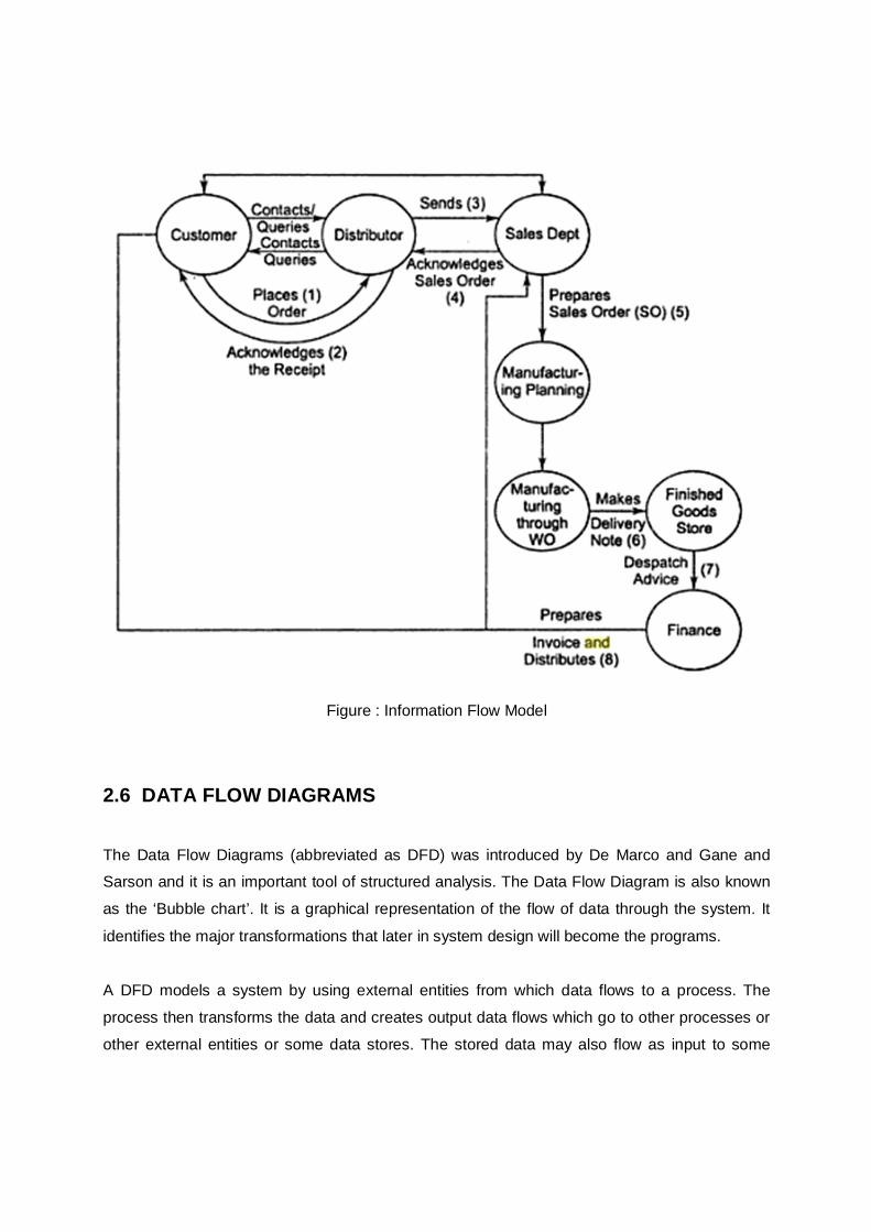
Figure : Information Flow Model
2.6 DATA FLOW DIAGRAMS
The Data Flow Diagrams (abbreviated as DFD) was introduced by De Marco and Gane and Sarson and it is an important tool of structured analysis. The Data Flow Diagram is also known
as the ‘Bubble chart’. It is a graphical representation of the flow of data through the system. It
identifies the major transformations that later in system design will become the programs.
A DFD models a system by using external entities from which data flows to a process. The
process then transforms the data and creates output data flows which go to other processes or
other external entities or some data stores. The stored data may also flow as input to some
processes. The advantage of DFD is that it provides an overview of what data the system would
process, what transformations are done on the data, which data are stored and where the
results flow. In other words, a DFD describes what data flow rather than how they are
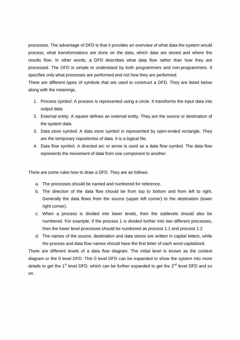
processed. The DFD is simple to understand by both programmers and non-programmers. It specifies only what processes are performed and not how they are performed.
There are different types of symbols that are used to construct a DFD. They are listed below along with the meanings.
1. Process symbol: A process is represented using a circle. It transforms the input data into
output data.
2. External entity: A square defines an external entity. They are the source or destination of
the system data.
3. Data store symbol: A data store symbol is represented by open-ended rectangle. They are the temporary repositories of data. It is a logical file.
4. Data flow symbol: A directed arc or arrow is used as a data flow symbol. The data flow
represents the movement of data from one component to another.
There are some rules how to draw a DFD. They are as follows:
a. The processes should be named and numbered for reference.
b. The direction of the data flow should be from top to bottom and from left to right. Generally the data flows from the source (upper left corner) to the destination (lower
right corner).
c. When a process is divided into lower levels, then the sublevels should also be
numbered. For example, if the process 1 is divided further into two different processes,
then the lower level processes should be numbered as process 1.1 and process 1.2
d. The names of the source, destination and data stores are written in capital letters, while
the process and data flow names should have the first letter of each word capitalized.
There are different levels of a data flow diagram. The initial level is known as the context
diagram or the 0 level DFD. This 0 level DFD can be expanded to show the system into more
details to get the 1st level DFD, which can be further expanded to get the 2nd level DFD and so on.
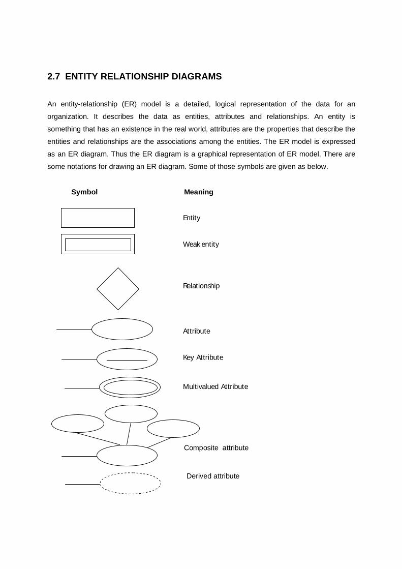
2.7 ENTITY RELATIONSHIP DIAGRAMS
An entity-relationship (ER) model is a detailed, logical representation of the data for an
organization. It describes the data as entities, attributes and relationships. An entity is
something that has an existence in the real world, attributes are the properties that describe the
entities and relationships are the associations among the entities. The ER model is expressed
as an ER diagram. Thus the ER diagram is a graphical representation of ER model. There are
some notations for drawing an ER diagram. Some of those symbols are given as below.
Symbol Meaning
Entity
Weak entity
Relationship
Attribute
Key Attribute Multivalued Attribute
Composite attribute
Derived attribute
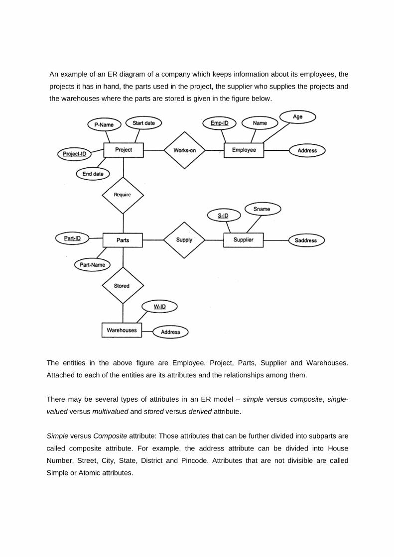
An example of an ER diagram of a company which keeps information about its employees, the
projects it has in hand, the parts used in the project, the supplier who supplies the projects and the warehouses where the parts are stored is given in the figure below.
The entities in the above figure are Employee, Project, Parts, Supplier and Warehouses.
Attached to each of the entities are its attributes and the relationships among them. There may be several types of attributes in an ER model – simple versus composite, single-
valued versus multivalued and stored versus derived attribute.
Simple versus Composite attribute: Those attributes that can be further divided into subparts are
called composite attribute. For example, the address attribute can be divided into House
Number, Street, City, State, District and Pincode. Attributes that are not divisible are called
Simple or Atomic attributes.
Require
Single-valued versus Multivalued attribute: Those attributes that have a single value for a
particular entity are called Single-valued attribute. For example, the age of a person is a single
valued attribute. In some cases, an attribute can have a set of values for the same entity. For
example, the attribute CollegeDegree for a person may be different for different persons. A person may have 0, 1 or more number of degrees.
Stored versus Derived attribute: Sometimes two (or more) attribute values may be related. For
example, the DateOfBirth and Age attributes of a person are related. The age of a person can
be determined from his DateOfBirth and the current date. Hence, the Age attribute is called a
derived attribute and the DateOfBirth attribute is called a stored attribute.
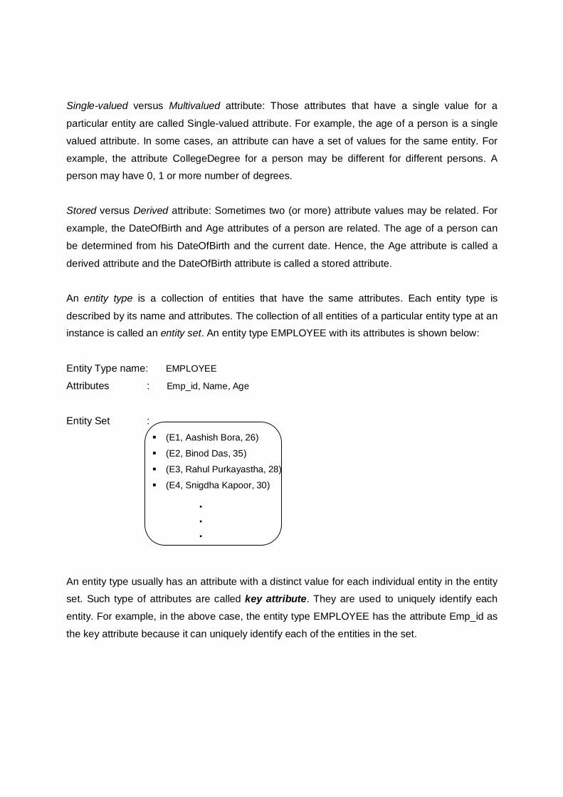
An entity type is a collection of entities that have the same attributes. Each entity type is
described by its name and attributes. The collection of all entities of a particular entity type at an instance is called an entity set. An entity type EMPLOYEE with its attributes is shown below:
Entity Type name: EMPLOYEE
Attributes : Emp_id, Name, Age
Entity Set : (E1, Aashish Bora, 26)
(E2, Binod Das, 35)
(E3, Rahul Purkayastha, 28)
(E4, Snigdha Kapoor, 30)
. . .
An entity type usually has an attribute with a distinct value for each individual entity in the entity set. Such type of attributes are called key attribute. They are used to uniquely identify each
entity. For example, in the above case, the entity type EMPLOYEE has the attribute Emp_id as
the key attribute because it can uniquely identify each of the entities in the set.
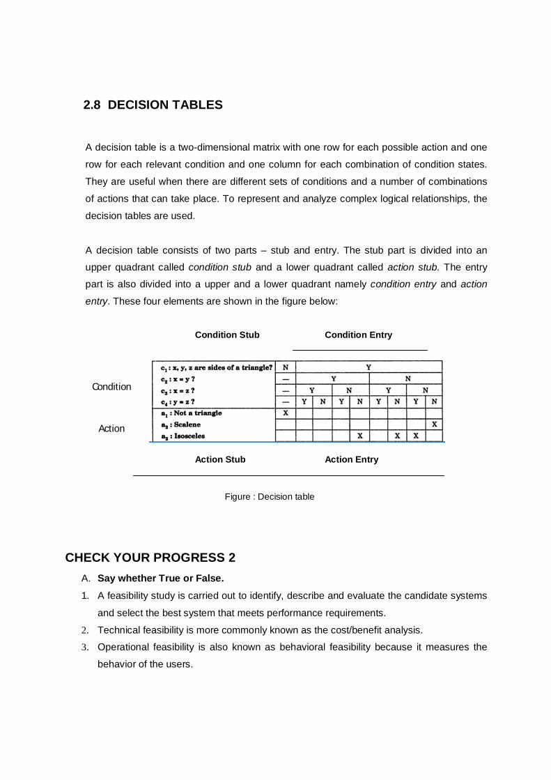
2.8 DECISION TABLES A decision table is a two-dimensional matrix with one row for each possible action and one
row for each relevant condition and one column for each combination of condition states.
They are useful when there are different sets of conditions and a number of combinations
of actions that can take place. To represent and analyze complex logical relationships, the
decision tables are used.
A decision table consists of two parts – stub and entry. The stub part is divided into an upper quadrant called condition stub and a lower quadrant called action stub. The entry part is also divided into a upper and a lower quadrant namely condition entry and action
entry. These four elements are shown in the figure below:
Condition Stub Condition Entry
Action Stub Action Entry
Figure : Decision table
CHECK YOUR PROGRESS 2
A. Say whether True or False. 1. A feasibility study is carried out to identify, describe and evaluate the candidate systems
and select the best system that meets performance requirements.
2. Technical feasibility is more commonly known as the cost/benefit analysis. 3. Operational feasibility is also known as behavioral feasibility because it measures the
behavior of the users.
Condition
Action
4. The Information Flow Model is a low-level model which shows detailed flows in the
system.
5. The DFD is a graphical representation of the flow of data through the system.
6. A DFD describes what data flow rather than how they are processed.
7. A data store symbol is represented by a circle.
8. The direction of the data flow in a DFD should be from bottom to top.
9. An entity is something that has an existence in the real world.
10. Attributes that have a single value for a particular entity are called Multivalued attribute.
11. Key attribute of an entity may not be unique.
12. A decision table is a two-dimensional matrix with one row for each possible action and
one row for each relevant condition and one column for each combination of condition states.
2.9 SRS DOCUMENT After elicitation and analysis, the analyst systematically organizes the requirements in the form
of a document called the Software Requirements Specification (SRS) document. This document
includes both the user requirements and a detailed specification of the system requirements. It
enlists all the necessary requirements that are required for the project development. The
possible users of the SRS document are Users and Customers:
The users refer to the document to ensure that the requirements specified will meet their
needs. The customers specify changes to the requirements. Software developers:
They refer to the document to ensure that the software is developed according to the
requirements. System Test Engineers:
They use the document to use the requirements to develop validation tests for the
system. Project Managers:
They use the document to estimate the cost of the project.
System Maintenance engineers:
This document helps them to understand the functionalities of the system and also gives
them a clear picture of the user requirements. They can then determine what modifications to
the functionalities of the system are required for a specific purpose. Characteristics of a good SRS document
1. Concise: The SRS document should be concise, complete, unambiguous and consistent
at the same time.
2. Structured: It should be well-structured to make it easy to understand and modify.
3. Traceable: It should be possible to trace a requirement to the design elements that
implements it and vice versa.
4. Verifiable: An SRS is verifiable if, and only if, every requirement stated therein is
verifiable. This means it should be possible to determine whether or not the requirements are met in the implementations. Requirements such as ‘user friendly’,
‘shall usually happen’ are not verifiable. The non-verifiable requirements should be
separately listed in the goals of implementation section of the SRS document.
5. Modifiable: An SRS is modifiable if, and only if, its structure and style are such that any
changes to the requirements can be made easily, completely, and consistently while
retaining the structure and style.
Sometimes an SRS document may have some problems like over-specification, forward references and wishful thinking. These should be avoided while writing and SRS document.
2.10 IEEE STANDARDS FOR SRS The most widely known standard for SRS document is IEEE/ ANSI 830-1998 (IEEE,1998). This
standard suggests the following structure for SRS document.
1. Introduction
1.1. Purpose of the SRS document
1.2. Scope of the product
1.3. Definitions, acronyms & abbreviations
1.4. References
1.5. Overview
2. Overall description
2.1. Product perspective
2.2. Product functions
2.3. User characteristics
2.4. Constraints
2.5. Assumptions and dependencies
3. Specific Requirements
3.1 External interface requirements 3.2 Specific requirements 3.3 Performance requirements
3.4 Design constraints
3.5 Software system attributes
3.6 Other requirements
4. Supporting information
4.1 Table of contents and index
4.2 Appendixes
The specific requirements cover the functional, non-functional and the interface requirements.
2.11 SOFTWARE QUALITY ASSURANCE (SQA)
The aim of Software Quality Assurance (SQA) is to develop high quality software product.
A good quality product does exactly what the users want it to do. Software Quality Assurance is
a set of activities that defines how software quality can be achieved and how the development
organization knows that the software has the required level of quality. If the quality in the
software development process is high then the errors are reduced in the developed product.
SQA includes the process of assuring that standards and procedures are established and are
followed throughout the software acquisition life cycle.
The main task of quality assurance is to define or select standards. There are two types of
standards that may be established as part of the quality assurance process:
1. Product standard: These apply to the software product being developed. It includes
standard of the document, the documentation and the coding standard. 2. Process standard: These define the processes that should be followed during the
software development process.
2.11.1 Verification and Validation During the development of the product and after its implementation, the programs must be
checked to ensure that they meets the specification given by the customer and delivers the
functionality expected by them. This checking and analysis processes are known as the
verification and the validation (V&V) processes.
Verification determines whether the output of one phase of software development confirms to
that of its previous phase. The validation process, on the other hand, determines whether the
fully developed system confirms to its requirements specification. The ultimate goal of these
processes is to establish the confidence that the system is ‘fit for the purpose’.
2.11.2 SQA Plans A Software Quality Assurance (SQA) plan consists of those procedures, techniques and tools
used to ensure that a product meets the requirements specified in software requirements
specification. It lays out the steps that has been planned to ensure quality levels in the system.
The SQA plan provides framework and guidelines for development of maintainable and
understandable code. Quality may cover areas such as correctness, usability, performance and
security. The SQA plan should identify which areas are more important and how to plan to achieve high quality. The SQA plan is developed by the software quality assurance group.
There are some steps how to develop and implement an SQA plan.
1. Document the plan
2. Obtain management acceptance: The management is responsible for both ensuring
the quality of the project and for providing the necessary resources required for
developing the software. 3. Obtain development acceptance: The software project development team members
are the main users of the plan and so their approval and cooperation in implementing
the plan is essential. They must accept the SQA plan and follow it. 4. Plan for implementation of the SQA plan: A schedule for drafting, reviewing and
approving the SAQ plan should be developed. i. Execute the SQA plan: The SQA plan is actually executed by the
software development and maintenance team.
2.12 ISO 9000 Models
International Standards Organization (ISO) is a consortium of 63 countries established to
formulate and foster standardization. The 9000 series of standards by ISO was published in
1987. The ISO 9000 is the set of standards that can be used in the development of a quality
management system (QMS) in the organizations. The ISO 9000 standards establish a standard
framework for a Quality System.
The guidelines for maintaining a quality system is specified in the ISO 9000 standard. These
standards define the quality systems or models applicable to design, development, production,
installation and servicing, final inspection and test. As all endeavors do not encompass all of
these business aspects, three standards were developed covering different combinations of
these disciplines. Guidelines were also issued to assist the industries in choosing the correct
standard. The aims of such standards are to assure consistency in the quality of products and services combined with continual improvement in customer satisfaction and error rates.
These three standards are ISO 9001, ISO 9001 and ISO 9003.
ISO 9001: This is the most general of the above standards. It applies to organizations concerned with the quality process in organizations engaged in design, development,
production and servicing of goods. ISO 9001 requires the development of quality
manual and documented procedures which define the organization and operation of the
quality system.
ISO 9002: This standard applies to those organizations which are involved in production,
installation and servicing. It is the model for quality systems that include production but
do not include design. For example, manufacturing industries such as car and steel who
buy the design from external sources and are only involved in its production. Thus the
ISO 9002 is not applicable to software development organizations.
ISO 9003: This standard applies to those organizations which are involved only in
installation and testing of the products.
2.13 SEI-CMM Model The Carnegie-Mellon University, USA created the SEI (Software Engineering Institute). It was
originally initiated by the U.S. Defense Department to help improve software development processes.
The Capability Maturity Model (CMM) was developed by the SEI. It was developed to assist the
US Department of Defence (US DoD) in purchasing software. This model helped the
organizations to improve the quality of the software they developed and thus the adoption of the SEI CMM model helped the organizations to gain competitive advantage.
The Capability Maturity Model is a reference model for apprising the software process maturity
into different levels. The SEI CMM has 5 levels of organizational ‘maturity’ that determine effectiveness in delivering quality software.
Level 1: Initial
At this level almost no software development processes are defined and followed. Software
engineers follow their own processes of development and so this level is characterized by
chaos, periodic panics, and heroic efforts required by individuals to successfully complete the projects.
Level 2: Repeatable
At this level, the basic management practices like software project cost tracking and scheduling
are established. The size and cost estimation techniques such as function point analysis, COCOMO etc are used. The success story of the development of a product can be repeated for the others.
Level 3: Defined
At this level, standard software development and maintenance processes are defined and also
documented. Organization-wide understanding of the roles and responsibilities exist. Periodic training programs are used to ensure understanding and compliance.
Level 4: Managed
Software metrics is used in this level. Tools like fishbone diagrams, Pareto charts etc are used to measure product and process quality. Project performance is evaluated in this level.
Level 5: Optimizing
The focus is on continuous process improvement. This is achieved by analyzing the quantitative
feedback from the process measurements and it can also be achieved from new and innovative ideas and technologies.
CHECK YOUR PROGRESS 3 1. Fill up the blanks:
a. The __________________ enlists all the necessary requirements that are required for
the project development.
b. The set of activities that defines how software quality can be achieved and how the
development organization knows that the software has the required level of quality is
called _______________________.
c. The two types of standards that may be established as part of the quality assurance
process are ____________________ and _______________________. d. __________________process determines whether the fully developed system confirms
to its requirements specification.
e. A ___________________________ is made to ensure that a product meets the
requirements specified in software requirements specification. f. The guidelines for maintaining a quality system is specified in the ___________
standard. g. The three standards of ISO 9000 are_________, ___________and_____________.
h. The ____________ is not applicable to software development organizations.
i. The __________________ was developed to assist the US Department of Defence in
purchasing software.
j. The SEI CMM has _______________ of organizational ‘maturity’ that determine
effectiveness in delivering quality software.
2.14Let Us Sum Up
1. Requirements Engineering is the process of establishing the services that the customer
requires from the system and the constraints under which it is to be developed and
operated.
2. It describes “what to do” and not the “how to do” of a software system. 3. The requirements are of two different types - Functional Requirements and Non-
functional Requirement
4. The steps in requirement engineering are – Elicitation, Analysis, Documentation, Review
and requirements management.
5. Elicitation is the first activity that takes place and continues through the requirement
engineering lifecycle.
6. Some information gathering tools in elicitation are Review of Literature, Procedures and
Forms, On-site observation and Interviews and Questionnaires.
7. In the analysis phase, each of the requirement is analyzed to understand the exact
customer requirements and also the software product to be developed.
8. In the documentation, the analyst organizes the requirements in a proper format in the
form of an SRS (Software Requirement Specification) document. The SRS document usually contains all the users’ requirements.
9. A requirement review is a manual process of evaluation or examination of the
requirements documents. It involves people from both the client and contractor
organization so as to check the documents for anomalies and omissions.
10. Requirements review can be informal or formal. 11. A feasibility study is carried out to identify, describe and evaluate the candidate systems
and select the best system that meets performance requirements.
12. Feasibility study can be categorized as economic, technical and operational feasibility.
13. An information model is used to describe the flow of information in a system.
14. The DFD is a graphical representation of the flow of data through the system. It identifies
the major transformations that later in system design will become the programs.
15. An entity-relationship (ER) model is a detailed, logical representation of the data for an
organization. It describes the data as entities, attributes and relationships.
16. There may be different types of attributes in an ER model : simple versus composite, single-valued versus multivalued and stored versus derived attribute.
17. An entity type usually has an attribute with a distinct value for each individual entity in
the entity set. Such type of attributes are called key attribute.
18. A decision table is a two-dimensional matrix with one row for each possible action and
one row for each relevant condition and one column for each combination of condition
states.
19. The Software Requirements Specification (SRS) document includes both the user
requirements and a detailed specification of the system requirements. It enlists all the
necessary requirements that are required for the project development.
20. The aim of Software Quality Assurance (SQA) is to develop high quality software product.
21. The main task of quality assurance is to define or select standards.
22. Verification determines whether the output of one phase of software development
confirms to that of its previous phase. The validation process, on the other hand,
determines whether the fully developed system confirms to its requirements
specification.
23. A Software Quality Assurance (SQA) plan consists of those procedures, techniques and
tools used to ensure that a product meets the requirements specified in software requirements specification.
24. The ISO 9000 is the set of standards that can be used in the development of a quality
management system (QMS) in the organizations. The ISO 9000 standards establish a
standard framework for a Quality System.
25. The Capability Maturity Model is a reference model for apprising the software process maturity into different levels. The SEI CMM has 5 levels of organizational ‘maturity’ that determine effectiveness in delivering quality software.
2.15 Further Readings 1. Systems Analysis and Design, 2nd Edition, Elias M Awad, Galgotia Publication
2. Software Engineering by Bharat Bhushan Agarwal, Sumit Prakash Tayal.
2.16 Answers To Check Your Progress Check Your Progress 1
1.a. Requirements Engineering
b. problem statement, system requirement specification
c. three
d. functional requirements and non-functional requirements
e. analyst, users
f. interview
g. Unstructured, semi-structured, structured. h. Domain understanding
i. Ambiguity, inconsistency, incompleteness
j. SRS document
Check Your Progress 2 A.1. True
2. False
3. True
4. False
5. True
6. True
7. False 8. False
9. True
10. False
11. False 12. True
Check Your Progress 3 1. a. SRS Document
b. Software Quality Assurance (SQA)
c. Product standard and Process standard
d. Validation
e. SQA Plan
f. ISO 9000
g. ISO 9001, ISO 9001, ISO 9003
h. ISO 9002
i. Capability Maturity Model
j. 5 levels
2.17 POSSIBLE QUESTIONS
1. What is requirement engineering? Explain the requirement engineering process.
2. Explain feasibility study and its different types.
3. What is Data flow Diagram? Draw the DFD for a Student Information System. 4. What is the importance of Software Quality Assurance?
UNIT 3 : STRUCTURED SYSTEM DESIGN
UNIT STRUCTURE
3.1 Learing Objectives
3.2 Introduction
3.3 What is Module?
3.3.1 Module Specifications
3.3.2 Advantages of Module Sharing
3.4 Structured Charts
3.5 Qualities of Good Design
3.6 Coupling
3.6.1 Types of Coupling
3.7 Cohesion
3.7.1 Types of Cohesion
3.8 Let Us Sum Up
3.9 Answer to Your Check Progress
3.10 Further Readings
3.11 Model Questions
3.1 LEARNING OBJECTIVES
After going through this unit, you will learn about
Modules and its specifications
Structured Charts
Qualities of Good Design
Coupling and its types
Cohesion and its types
3.2 INTRODUCTION
The structured design approach was first developed by Stevens,
Myers and Constantine. It is a data-flow-based methodology that indentifies
inputs and ouputs and describes the functional aspects of the system. It
partitions a system into a number of integrated components that provides
functionality to the system by which the system can implement tasks.
Modularity makes the system modifiable, extendable and maintainable.
3.3 WHAT IS A MODULE?
Modules represent manageable components of the software which
can be easily integrated to satisfy the problem requirements. The modules
should be designed so that they have minimum effect on other modules of
the software. The connection of the modules should be limited and the
interaction of data should also be minimal. Such design objectives are
intended to improve the software quality while easing with maintenance tasks.
Every system should consist of a hierarchy of modules. Lower-level modules
are generally smaller in scope and size compared to higher-level modules
and they serve to partition processes into separate functions.
Different methods are used to define modules within a system. Meyer
defines five criteria for evaluating a design method with respect to its ability
for an effective modular system :
i) Modular decomposability : If a design method provides a
systematic mechanism for decomposing the problem into
subproblems, it will reduce the complexity of the overall problem,
thereby achieving an effective modular solution.
ii) Modular composability : If a design method enables existing design
components to be assembled into a new system, it will yield a modular
solution.
iii) Modular understandability : If a module can be understood as a
standalone unit (without reference to other modules), it will be easier
to build and easier to change.
iv) Module continuity : If small changes to the system requirements
result in changes to individual modules, rather than systemwide
changes, the impact of change-induced side effects will be
minimized.
v) Modular protection: If an aberrant condition occurs within a module
and its effects are constrained within that module, the impact of
error-induced side effects will be minimized.
3.3.1 Module Specifications
Modules have the following specifications:
They may have little or no dependence on other modules in
a system
They should carry out a single processing function.
They should interact with and manage functions of a limited
number of lower-level modules
The number of instructions contained in a module should be
limited so that module size is generally small.
Functions should not be duplicated in separate modules.
They should be established in a single module that can be
invoked by any other module when needed.
Failure or change in one module shouldn’t affect other
modules.
3.3.2 Advantages of Modules Sharing
1. Sharing modules minimizes the amount of software that must
be designed and written.
2. It minimizes the number of changes that must be made
during the software maintenance.
3. It reduces the chance of error.
3.4 STRUCTURED CHARTS
Structure charts are important tool for the software designer in
representing the software architecture. They visually display the relationship
between program modules making up the system and graphically show the
data communicated between each module. It shows which module within a
system interacts. Structure charts are developed prior to the writing of
program code. Since the main focus in a structure chart representation is
on the module structure of the software and the interactions among different
modules, the procedural aspects are not represented here.
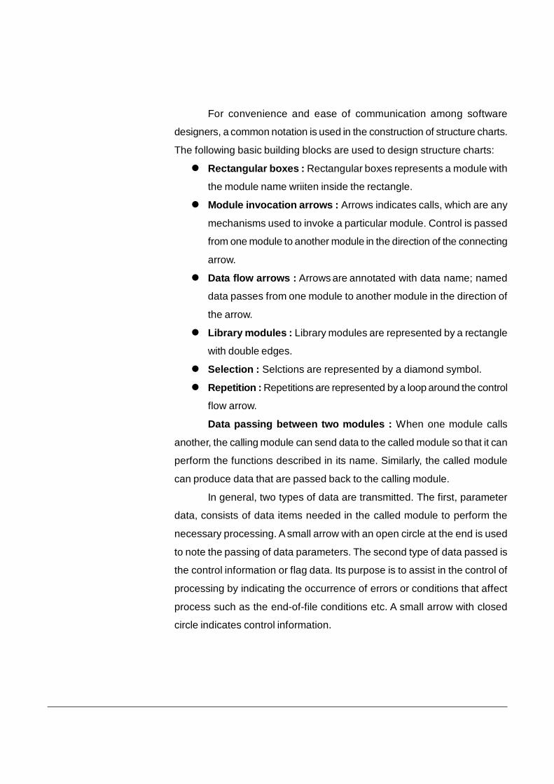
For convenience and ease of communication among software
designers, a common notation is used in the construction of structure charts.
The following basic building blocks are used to design structure charts:
Rectangular boxes : Rectangular boxes represents a module with
the module name wriiten inside the rectangle.
Module invocation arrows : Arrows indicates calls, which are any
mechanisms used to invoke a particular module. Control is passed
from one module to another module in the direction of the connecting
arrow.
Data flow arrows : Arrows are annotated with data name; named
data passes from one module to another module in the direction of
the arrow.
Library modules : Library modules are represented by a rectangle
with double edges.
Selection : Selctions are represented by a diamond symbol.
Repetition : Repetitions are represented by a loop around the control
flow arrow.
Data passing between two modules : When one module calls
another, the calling module can send data to the called module so that it can
perform the functions described in its name. Similarly, the called module
can produce data that are passed back to the calling module.
In general, two types of data are transmitted. The first, parameter
data, consists of data items needed in the called module to perform the
necessary processing. A small arrow with an open circle at the end is used
to note the passing of data parameters. The second type of data passed is
the control information or flag data. Its purpose is to assist in the control of
processing by indicating the occurrence of errors or conditions that affect
process such as the end-of-file conditions etc. A small arrow with closed
circle indicates control information.
3.5 QUALITIES OF GOOD DESIGN
Software design deals with transforming the customer requirements,
as described in the SRS document, into a form that is suitable for
implementation in a programming language. A good software design is
seldom arrived by using a single step procedure but rather through several
iterations through a series of steps. Design activities can be broadly
classified into two important parts:
Preliminary (or high-level) design and
Detailed design.
Preliminary design means identification of different modules and their
control relationships and the definition of the interfaces among these
modules. Program structure or software architecture is the outcome of the
preliminary design. Many different types of notations are used to represent
a preliminary design. A popular method is to use a tree-like diagram called
the structure chart to represent the control hierarchy in a high-level design.
However, other notations such as Jackson diagram or Warnier-Orr diagram
can also be used. During detailed design, the data structure and the
algorithms of the different modules are designed. The outcome of the detailed
design stage is usually known as the module-specification document.
Characteristics of a good software design : A software design is
a description of the structure of the software to be implemented, the data
DataParameters Control
Informationor
Flag Data
Module A
Module B
which is the part of the system, the interfaces between system components
and, sometimes, the algorithms used. Designers do not arrive at a finished
design immediately but develop the design iteratively through a number of
versions. The design process involves adding formality and detail as the
design is developed with constant backtracking to correct earlier designs.
The definition of a good software design can vary depending on the
application being designed. For example, the memory size used by a
program may be an important issue to characterize a good solution for
embedded software development – since embedded applications are often
required to be implemented using memory of limited size due to cost, space,
or power consumption considerations. Similarly, a simple user interactivity
may be a mojor issue in case of ATMs of a bank. Therefore, the criteria
used to judge a software design can vary widely depending upon the
application. Not only is the goodness of design dependent on the targeted
application, but also the notion of goodness of a design itself varies widely
across software engineers and academicians. However, most researchers
and software engineers agree on a few desirable characteristics that every
good software design for general application must possess. The
characteristics are listed below:
Correctness : A good design should implement all the functionalities
identified in the SRS document in a correct way.
Understandability : A good design should be easily understandable.
Efficiency : It should be efficient.
Maintainability : It should be easily amenable to change.
The most important criterion for a good design is its correctness. A
correct design is easily acceptable. When a design solution is correct, next
important issue in judging the goodness of a design is understandability of
the design. A design that is easy to understand is also easy to develop,
maintain and change. Thus, unless a design is easily understandable, it
would require tremendous effort to implement and maintain it.
CHECK YOUR PROGRESS
Q.1. What are modules?
.............................................................................................
Q.2. Mention three specifications of a module.
.............................................................................................
.............................................................................................
.............................................................................................
Q.3. What are the differences between structured charts and flow
charts?
.............................................................................................
.............................................................................................
.............................................................................................
Q.4. Write two features of a structured design.
.............................................................................................
.............................................................................................
3.6 COUPLING
Coupling refers to the strength of the relationship between modules
in a system. It is a measure of interconnection among modules in software
structure. Thus, module coupling refers to the number of connections
between a “calling” and a “called” module and the complexity of these
connections. There must be at least one connection between a module and
a calling module. In general, good designers seek to develop the structure
of a system so that one module has the little dependence on any other
module. If two modules interchange large amount of data, then they are
highly interdependent. Loose coupling minimizes the interdependence
between modules. This can be achieved in the following ways:
Control the number of parameters passed between modules
Avoid passing unnecessary data to called modules
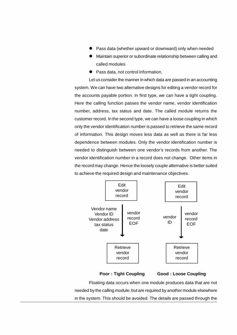
Pass data (whether upward or downward) only when needed
Maintain superior or subordinate relationship between calling and
called modules
Pass data, not control information.
Let us consider the manner in which data are passed in an accounting
system. We can have two alternative designs for editing a vendor record for
the accounts payable portion. In first type, we can have a tight coupling.
Here the calling function passes the vendor name, vendor identification
number, address, tax status and date. The called module returns the
customer record. In the second type, we can have a loose coupling in which
only the vendor identification number is passed to retrieve the same record
of information. This design moves less data as well as there is far less
dependence between modules. Only the vendor identification number is
needed to distinguish between one vendor’s records from another. The
vendor identification number in a record does not change. Other items in
the record may change. Hence the loosely couple alternative is better suited
to achieve the required design and maintenance objectives.
Floating data occurs when one module produces data that are not
needed by the calling module; but are required by another module elsewhere
in the system. This should be avoided. The details are passed through the
Editvendorrecord
Editvendorrecord
Retrievevendorrecord
Retrievevendorrecord
Poor : Tight Coupling Good : Loose Coupling
Vendor nameVendor ID
Vendor addresstax status
date
vendorrecordEOF
vendorID
vendorrecordEOF
system until they finally reach the function that requires them. Redesigning
to establish loose coupling, along with the creation of more cohesive modules
will avoid this difficulty.
3.6.1 Types of Coupling
There are different types of coupling, each having its
consequences on design. In order of high to low coupling following
types of couplings can occur:
Content coupling : When a module modifies the internal state or
behaviour of another module, i.e. if one module alters the contents
of another, then the process is called content coupling.
Common coupling : In common coupling, two modules share the
same global data items or resourcces. This coupling forces changes
in all modules sharing a particular resource when any modifications
in the resource type or its name occur.
External coupling : External coupling occurs when two modules
share an externally imposed data format, communication protocol,
or device interface. For example, two communicating modules on a
network share a common packet format and any change in the packet
format of one module must be implemented in the other too; or else
the communication will fail or be faulty.
Control coupling : When one module controls the logic of another
module, then the process is termed as control module. It occurs
when one module provides information to the other and the other
takes the action based on this information. For example, flag set in
one module and tested in another module.
Stamp coupling : Two modules are stamp coupled, if they
communicate by sharing a composite data structure but preferably
using the the different part. For example, a record in PASCAL and a
structure in C are stamp coupling.
Data coupling : Two couples are data coupled, if they communicate
using an elementary data item that is passed as parameters between
the two. The parameters that are passed are usually atomic or intrinsic
data types of programming language, e.g. an integer, a character, a
float etc.
Message coupling : This is the loosest type of coupling. In this
coupling, modules are not dependent on each other; rather they use
a static interface to communicate. This communication is via
parameter-less messages. Message coupling is an important
feature of object-oriented programming.
3.7 COHESION
Module cohesion refers to the relationship among elements within a
module. If a module does more than one discrete task, the instructions in
that module are said not to be bound together very closely. Modules that
perform only one task are said to be more cohesive and is less error-prone
than modules that perform multiple tasks.
Cohesion is a measure of the strength of the relationships between
the responsibilities of components of a module. A module is said to be higly
cohesive if its components are strongly related to each other by some
means of communication or resource sharing or the nature of
responsibilities. Therefore, the cohesion may be understood as a measure
of relatedness of elements of a module. High cohesion is a symbol of good
design as it facilitates execution of a task by maximum intra-modular
communication and least inter-module dependencies. It promotes
independencies among the modules.
Designer should create strong cohesive modules with loose coupling,
i.e. the elements of a module should be tightly related to each other and
elements of one module should not be strongly related to the elements of
other modules. He should maintain a trade-off so that the modularity of the
system is conserved with optimum cohesion and bearable coupling. For
this, the partitioning of the system into modules should be done carefully
and modules should be clearly seperated from each other.
3.7.1 Types of Cohesion
The different types of cohesion that a module may possess
in order of worst to best type are given below :
Coincidental cohesion : A module is said to possess coincidental
cohesion if it performs a set of tasks that relate to each other very
loosely, if at all. Their activities are related neither by flow of data nor
by flow of control and they do not contribute any meaningful
relationship. In fact, the module contains a randeom collection of
functions which have least relations among them.
Logical cohesion : A module is said to be logically cohesive, if all
elements of the module perform similar operations even they are
diffrent by nature. For example, grouping mouse and keyboard as
input handling routine is a logical cohesion.
Temporal cohesion : When a module contains functions that are
related by the fact that all the functions must be executed in the
same time span, the module is said to exhibit temporal cohesion.
They binds the components which are processed at a particular
time or event in the program execution. For example, all the
exceptions, like closing all files, creating an error log and notifing the
users, may be kept in a single module, called ‘exception handler’,
which will be proceesed when the system encounters an exception.
Procedural cohesion : A module is said to have procedural
cohesion if all the elements follow certain sequence of occurrence
to be carried out for achieving an objective. The elements may be
involved in different and mostly unrelated activities. For example, a
function that checks the file permissions of a file and then opens the
file, possess a procedural cohesion.
Communicational cohesion : A module is said to have
communicational cohesion, if all components of the module operate
on same data elements, e.g. components working on the same
records of a database.
Sequential cohesion : A module is said to have sequential
cohesion, if components of the module are grouped such that output
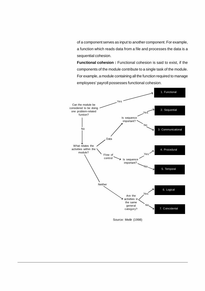
of a component serves as input to another component. For example,
a function which reads data from a file and processes the data is a
sequential cohesion.
Functional cohesion : Functional cohesion is said to exist, if the
components of the module contribute to a single task of the module.
For example, a module containing all the function required to manage
employees’ payroll possesses functional cohesion.
What relates theactivities within the
module?
No
Data
Flow ofcontrol
Neither
Is sequenceimportant?
Are theactivities inthe samegeneral
category?
Yes
No
Yes
No
Can the module beconsidered to be doing
one problem-relatedfuntion?
1. Functional
Yes
4. Procedural
6. Logical
7. Coincidental
2. Sequential
3. Communicational
Is sequenceimportant?
Yes
No
5. Temporal
Source: Meilir (1998)
CHECK YOUR PROGRESS
Q.5. Fill in the blanks:
i) __________ is a measure of the strength of the
relationships between the responsibilities of components
of a module.
ii) __________ is the weakest coupling.
iii) Coincidental cohesion has the __________ priority.
Q.6. Give two advantages of tightly coupled systems.
.............................................................................................
.............................................................................................
.............................................................................................
Q.7. What are the different types of coupling?
.............................................................................................
.............................................................................................
Q.8. Give an example of logical cohesion.
.............................................................................................
.............................................................................................
3.8 LET US SUM UP
Modules represent manageable components of the software which
can be easily integrated to satisfy the problem requirements.
The modules should be designed so that they have minimum effect
on other modules of the software.
Meyer defines five criteria for evaluating a design method with respect
to its ability for an effective modular system: decomposability,
composability, understandability, continuity and protection.
Structure charts visually display the relationship between program
modules making up the system and graphically show the data
communicated between each module. It shows which module within
a system interacts. They are developed prior to the writing of program
code.
The definition of a good software design can vary depending on the
application being designed.
Coupling refers to the strength of the relationship between modules
in a system. It is a measure of interconnection among modules in
software structure.
Different types of coupling are : Content coupling, Common coupling,
External coupling, Control coupling, Stamp coupling, Data coupling
and Message coupling.
Module cohesion refers to the relationship among elements within a
module. Modules that perform only one task are said to be more
cohesive and is less error-prone than modules that perform multiple
tasks.
Different types of cohesion are : Coincidental, Logical, Temporal,
Procedural, Communicational, Sequential and Functional.
3.9 ANSWERS TO CHECK YOUR PROGRESS
Ans. to Q. No. 1. Modules are manageable components of the software
which can be easily integrated to satisfy the problem requirements.
Ans. to Q. No. 2. i) They may have little or no dependence on other
modules in a system
ii) They should carry out a single processing function.
iii) The number of instructions contained in a module should be limited
so that module size is generally small.
Ans. to Q. No. 3. i) Structured charts visually display the relationship
between program modules making up the system
and graphically show the data communicated between each module.
But, Flow chart is a convenient technique to represent the flow of
control in a program.
ii) Data interchange among different modules is not represented in a
flow chart.
iii) Sequential ordering of tasks inherent in a flow chart is suppressed
in a structure chart.
Ans. to Q. No. 4. i) The design should be modular.
ii) It should neatly arrange the modules in a hierarchy, e.g. in a tree-like
diagram.
Ans. to Q. No. 5. i) Cohesion, ii) Message coupling, iii) lowest
Ans. to Q. No. 6. i) Assembly of modules might require more effort and
time due to the increased inter-module dependency.
ii) A particular module might be harder to reuse because dependent
modules must be included.
Ans. to Q. No. 7. Content coupling, Common coupling, External coupling,
Control coupling, Stamp coupling, Data coupling and Message coupling.
Ans. to Q. No. 8. Grouping mouse and keyboard as input handling routine
is an example of logical cohesion.
3.10 FURTHER READINGS
Pressman, Roger S., Software Engineering : A Practitioner’s
Approach, McGraw Hill Internation Edition.
Mall, Rajiv, Fundamentals of Software Engineering.
Awad, Elias M., Systems Analysis and Design,Galgotia Publication
Pvt. Ltd.
3.11 MODEL QUESTIONS
Q.1. What is/are the cause(s) of coupling in modules?
(i) Inter-module linkages (ii) Intra-module linkages
(iii) Environmental linkages (iv) All of the above
(v) None of the above
Q.2. What is/are the cause(s) of cohesion in module?
(i) Inter-module linkages (ii) Intra-module linkages
(iii) Environmental linkages (iv) All of the above
(v) None of the above
Q.3. Which of the follwing facts is/are true?
(i) Increase in cohesion would decrease coupling
(ii) Highest cohesion is most preferred
(iii) Lowest coupling is most preferred
(iv) All of the above
(v) None of the above
Q.4. Module A writes in some attributes of module B. What type of coupling
is there between A and B?
(i) Content (ii) Common
(iii) External (iv) Control
(v) Data
Q.5. Explain and illustrate the key elements of a structure chart.
Q.6. Differentiate between cohesion and coupling.
Q.7. Explain different types of cohesion and coupling with examples.
Software Testing Unit 4
1
UNIT - 4: SOFTWARE TESTING UNIT STRUCTURE
4.1 Learning Objectives 4.2 Introduction 4.3 Testing Objectives 4.4 Unit Testing
4.4.1 Unit Test considerations 4.4.2 Unit Test procedures
4.5 Integration Testing 4.5.1 Top-down integration 4.5.2 Bottom up integration
4.6 Acceptance (Alpha and Beta) Testing 4.7 Regression Testing 4.8 Structural Testing (White Box Testing) 4.9 Functional Testing (Black Box Testing) 4.10 Test Data Suit Preparation 4.11 Static Testing Strategies
4.11.1 Formal Technical Reviews 4.11.2 Code Walk Through 4.11.3 Code Inspection
4.12 Let Us Sum Up 4.13 Answers to Check Your Progress 4.14 Further Readings 4.15 Possible Questions
4.1 LEARNING OBJECTIVES
After going through this unit, you will be able to:
learn what software testing is
know software testing and the software testing processes
learn about the different software testing techniques
understand the top down testing strategy
know the bottom up testing technique
differentiate between black box and white box testing
Software Testing Unit 4
2
4.2 INTRODUCTION
After going through the previous units of this course, we learnt many concepts involved with the subject of Software Engineering. The various components that were associated with the process of Software Engineering have already been discussed at length. Also in the previous unit, we came to know about some basic concepts of the Software design process like architectural design, low-level designs, Pseudo codes, flow charts, coupling and cohesion measures etc. Apart from that, few other topics relating to software measurement and metrics that enable us to gain insight by providing a mechanism for objective evaluation were also discussed at length.
In this unit, we get introduced to the concept of Software testing which is a very important phase in the process of any kind of software development process in order to ensure the successful production of a fully functional and error-free final product. Software testing is a critical element of software quality assurance and represents the ultimate review of specification, design, and code generation. The increasing visibility of software as a system element and the attendant "costs" associated with a software failure are motivating forces for well-planned, thorough testing. In this unit we discuss software testing fundamentals and techniques for software test case design. Software testing fundamentals define the overriding objectives for software testing. 4.3 TESTING OBJECTIVES Testing presents an interesting anomaly for the software engineer. During the earlier software engineering activities, the engineer attempts to build software from an abstract concept to a tangible product. Then comes the testing process where the engineer creates a series of test cases that are intended to "demolish" the software that has been built. In fact, testing is the one step in the software process that could be viewed as destructive rather than constructive. Software engineers are by their nature constructive people. Testing requires that the developer discard preconceived notions of the "correctness" of software just developed and overcome a conflict of interest that occurs when errors are uncovered. Testing is intended to show that a program does what it is intended to do and to discover program defects before it is put into use. When we test software, we execute a program using artificial data. We check the results of the test run for errors, anomalies, or information about the program’s non-functional attributes. The testing process has two distinct goals:
1. To demonstrate to the developer and the customer that the software meets its requirements. For custom software, this means that there should be at least one test for every requirement in the requirements document. For generic software products, it means that there should be tests for
Software Testing Unit 4
3
all of the system features, plus combinations of these features, that will be incorporated in the product release.
2. To discover situations in which the behavior of the software is incorrect, undesirable, or does not conform to its specification. These are a consequence of software defects. Defect testing is concerned with rooting out undesirable system behavior such as system crashes, unwanted interactions with other systems, incorrect computations, and data corruption.
These objectives imply a dramatic change in viewpoint. They move counter to the commonly held view that a successful test is one in which no errors are found. Our objective is to design tests that systematically uncover different classes of errors and to do so with a minimum amount of time and effort. If testing is conducted successfully, it will uncover errors in the software. As a secondary benefit, testing demonstrates that software functions appear to be working according to specification, that behavioral and performance requirements appear to have been met. In addition, data collected as testing is conducted provide a good indication of software reliability and some indication of software quality as a whole. But testing cannot show the absence of errors and defects, it can show only that software errors and defects are present. It is important to keep this statement in mind as testing is being conducted.
4.4 UNIT TESTING Unit testing is the process of testing program components, such as methods or object classes. Individual functions or methods are the simplest type of component. Unit testing focuses verification effort on the smallest unit of software design—the software component or module. Using the component-level design description as a guide, important control paths are tested to uncover errors within the boundary of the module. The relative complexity of tests and uncovered errors is limited by the constrained scope established for unit testing. 4.4.1 UNIT TEST CONSIDERATIONS The tests that occur as part of unit tests are illustrated schematically in Figure 4.1. The module interface is tested to ensure that information properly flows into and out of the program unit under test. The local data structure is examined to ensure that data stored temporarily maintains its integrity during all steps in an algorithm's execution. Boundary conditions are tested to ensure that the module operates properly at boundaries established to limit or restrict processing. All independent paths (basis paths) through the control structure are exercised to ensure that all statements in a module have been executed at least once. And finally, all error handling paths are tested.
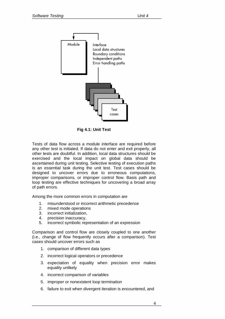
Software Testing Unit 4
4
Fig 4.1: Unit Test Tests of data flow across a module interface are required before any other test is initiated. If data do not enter and exit properly, all other tests are doubtful. In addition, local data structures should be exercised and the local impact on global data should be ascertained during unit testing. Selective testing of execution paths is an essential task during the unit test. Test cases should be designed to uncover errors due to erroneous computations, improper comparisons, or improper control flow. Basis path and loop testing are effective techniques for uncovering a broad array of path errors.
Among the more common errors in computation are 1. misunderstood or incorrect arithmetic precedence 2. mixed mode operations 3. incorrect initialization, 4. precision inaccuracy, 5. incorrect symbolic representation of an expression
Comparison and control flow are closely coupled to one another (i.e., change of flow frequently occurs after a comparison). Test cases should uncover errors such as
1. comparison of different data types 2. incorrect logical operators or precedence 3. expectation of equality when precision error makes
equality unlikely 4. incorrect comparison of variables 5. improper or nonexistent loop termination 6. failure to exit when divergent iteration is encountered, and
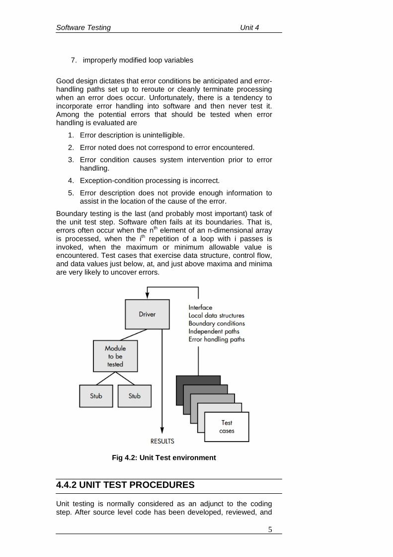
Software Testing Unit 4
5
7. improperly modified loop variables Good design dictates that error conditions be anticipated and error-handling paths set up to reroute or cleanly terminate processing when an error does occur. Unfortunately, there is a tendency to incorporate error handling into software and then never test it. Among the potential errors that should be tested when error handling is evaluated are
1. Error description is unintelligible. 2. Error noted does not correspond to error encountered. 3. Error condition causes system intervention prior to error
handling. 4. Exception-condition processing is incorrect. 5. Error description does not provide enough information to
assist in the location of the cause of the error. Boundary testing is the last (and probably most important) task of the unit test step. Software often fails at its boundaries. That is, errors often occur when the nth element of an n-dimensional array is processed, when the ith repetition of a loop with i passes is invoked, when the maximum or minimum allowable value is encountered. Test cases that exercise data structure, control flow, and data values just below, at, and just above maxima and minima are very likely to uncover errors.
Fig 4.2: Unit Test environment
4.4.2 UNIT TEST PROCEDURES
Unit testing is normally considered as an adjunct to the coding step. After source level code has been developed, reviewed, and
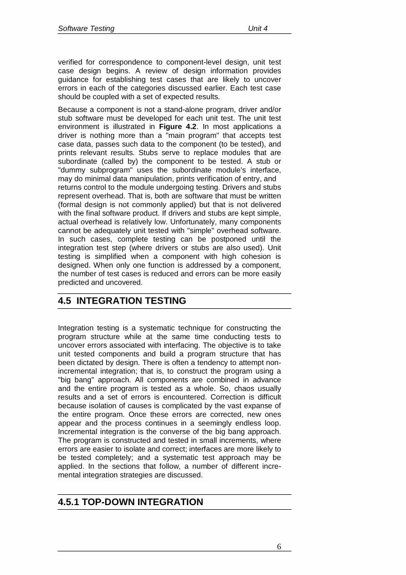
Software Testing Unit 4
6
verified for correspondence to component-level design, unit test case design begins. A review of design information provides guidance for establishing test cases that are likely to uncover errors in each of the categories discussed earlier. Each test case should be coupled with a set of expected results. Because a component is not a stand-alone program, driver and/or stub software must be developed for each unit test. The unit test environment is illustrated in Figure 4.2. In most applications a driver is nothing more than a "main program" that accepts test case data, passes such data to the component (to be tested), and prints relevant results. Stubs serve to replace modules that are subordinate (called by) the component to be tested. A stub or "dummy subprogram" uses the subordinate module's interface, may do minimal data manipulation, prints verification of entry, and returns control to the module undergoing testing. Drivers and stubs represent overhead. That is, both are software that must be written (formal design is not commonly applied) but that is not delivered with the final software product. If drivers and stubs are kept simple, actual overhead is relatively low. Unfortunately, many components cannot be adequately unit tested with "simple" overhead software. In such cases, complete testing can be postponed until the integration test step (where drivers or stubs are also used). Unit testing is simplified when a component with high cohesion is designed. When only one function is addressed by a component, the number of test cases is reduced and errors can be more easily predicted and uncovered. 4.5 INTEGRATION TESTING Integration testing is a systematic technique for constructing the program structure while at the same time conducting tests to uncover errors associated with interfacing. The objective is to take unit tested components and build a program structure that has been dictated by design. There is often a tendency to attempt non-incremental integration; that is, to construct the program using a "big bang" approach. All components are combined in advance and the entire program is tested as a whole. So, chaos usually results and a set of errors is encountered. Correction is difficult because isolation of causes is complicated by the vast expanse of the entire program. Once these errors are corrected, new ones appear and the process continues in a seemingly endless loop. Incremental integration is the converse of the big bang approach. The program is constructed and tested in small increments, where errors are easier to isolate and correct; interfaces are more likely to be tested completely; and a systematic test approach may be applied. In the sections that follow, a number of different incre-mental integration strategies are discussed. 4.5.1 TOP-DOWN INTEGRATION
Software Testing Unit 4
7
Top-down integration testing is an incremental approach to construction of program structure. Modules are integrated by moving downward through the control hierarchy, beginning with the main control module (main program). Modules subordinate (and ultimately subordinate) to the main control module are incorporated into the structure in either a depth-first or breadth-first manner.
Fig 4.3: Top-down integration
Referring to Figure 4.3, depth-first integration would integrate all components on a major control path of the structure. Selection of a major path is somewhat arbitrary and depends on application-specific characteristics. For example, selecting the left-hand path, components M1, M2, M5 would be integrated first. Next, M8 or (if necessary for proper functioning of M2) M6 would be integrated. Then, the central and right-hand control paths are built. Breadth-first integration incorporates all components directly subordinate at each level, moving across the structure horizontally. From the figure, components M2, M3, and M4 (a replacement for stub S4) would be integrated first. The next control level, M5, M6, and so on, follows. The integration process is performed in a series of five steps:
1. The main control module is used as a test driver and stubs are substituted for all components directly subordinate to the main control module.
2. Depending on the integration approach selected (i.e., depth or breadth first), subordinate stubs are replaced one at a time with actual components.
3. Tests are conducted as each component is integrated. 4. On completion of each set of tests, another stub is replaced
with the real component. 5. Regression testing may be conducted to ensure that new
errors have not been introduced.
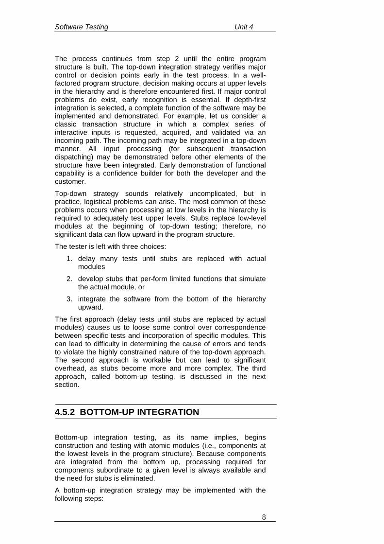
Software Testing Unit 4
8
The process continues from step 2 until the entire program structure is built. The top-down integration strategy verifies major control or decision points early in the test process. In a well-factored program structure, decision making occurs at upper levels in the hierarchy and is therefore encountered first. If major control problems do exist, early recognition is essential. If depth-first integration is selected, a complete function of the software may be implemented and demonstrated. For example, let us consider a classic transaction structure in which a complex series of interactive inputs is requested, acquired, and validated via an incoming path. The incoming path may be integrated in a top-down manner. All input processing (for subsequent transaction dispatching) may be demonstrated before other elements of the structure have been integrated. Early demonstration of functional capability is a confidence builder for both the developer and the customer. Top-down strategy sounds relatively uncomplicated, but in practice, logistical problems can arise. The most common of these problems occurs when processing at low levels in the hierarchy is required to adequately test upper levels. Stubs replace low-level modules at the beginning of top-down testing; therefore, no significant data can flow upward in the program structure. The tester is left with three choices:
1. delay many tests until stubs are replaced with actual modules
2. develop stubs that per-form limited functions that simulate the actual module, or
3. integrate the software from the bottom of the hierarchy upward.
The first approach (delay tests until stubs are replaced by actual modules) causes us to loose some control over correspondence between specific tests and incorporation of specific modules. This can lead to difficulty in determining the cause of errors and tends to violate the highly constrained nature of the top-down approach. The second approach is workable but can lead to significant overhead, as stubs become more and more complex. The third approach, called bottom-up testing, is discussed in the next section. 4.5.2 BOTTOM-UP INTEGRATION Bottom-up integration testing, as its name implies, begins construction and testing with atomic modules (i.e., components at the lowest levels in the program structure). Because components are integrated from the bottom up, processing required for components subordinate to a given level is always available and the need for stubs is eliminated. A bottom-up integration strategy may be implemented with the following steps:
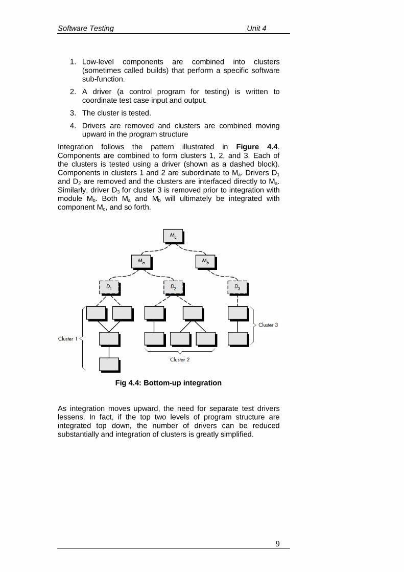
Software Testing Unit 4
9
1. Low-level components are combined into clusters (sometimes called builds) that perform a specific software sub-function.
2. A driver (a control program for testing) is written to coordinate test case input and output.
3. The cluster is tested. 4. Drivers are removed and clusters are combined moving
upward in the program structure Integration follows the pattern illustrated in Figure 4.4. Components are combined to form clusters 1, 2, and 3. Each of the clusters is tested using a driver (shown as a dashed block). Components in clusters 1 and 2 are subordinate to Ma. Drivers D1 and D2 are removed and the clusters are interfaced directly to Ma. Similarly, driver D3 for cluster 3 is removed prior to integration with module Mb. Both Ma and Mb will ultimately be integrated with component Mc, and so forth.
Fig 4.4: Bottom-up integration
As integration moves upward, the need for separate test drivers lessens. In fact, if the top two levels of program structure are integrated top down, the number of drivers can be reduced substantially and integration of clusters is greatly simplified.
Software Testing Unit 4
10
1. Fill in the blanks: (a) Unit testing focuses __________ effort on the smallest unit
of software design. (b) Selective testing of execution paths is an essential task
during the __________. (c) Basis path and loop testing are effective techniques for
uncovering a broad array of __________. (d) _______________ is the last task of the unit test step. (e) Drivers and stubs represent __________. (f) If drivers and stubs are kept _______, actual overhead is
relatively ____. (g) Unit testing is ________ when a component with high
________ is designed. (h) Integration testing is a systematic technique for
constructing the __________ while at the same time conducting tests to uncover errors associated with _________.
(i) The top-down integration strategy verifies major _______ or _______ points early in the test process.
(j) In bottom up integration _________ components are combined into _________ that perform a specific software sub-function.
4.6 ACCEPTANCE (ALPHA AND BETA) TESTING This is the final stage in the testing process before the system is accepted for operational use. The system is tested with data supplied by the system customer rather than with simulated test data. Acceptance testing may reveal errors and omissions in the system requirements definition, because the real data exercise the system in different ways from the test data. Acceptance testing may also reveal requirements problems where the system’s facilities do not really meet the user’s needs or the system performance is unacceptable. It is virtually impossible for a software developer to foresee how the customer will really use a program. Instructions for use may be misinterpreted; strange combinations of data may be regularly used; output that seemed clear to the tester may be unintelligible
CHECK YOUR PROGRESS
Software Testing Unit 4
11
to a user in the field. When custom software is built for one customer, a series of acceptance tests are conducted to enable the customer to validate all requirements. Conducted by the end-user rather than software engineers, an acceptance test can range from an informal "test drive" to a planned and systematically executed series of tests. In fact, acceptance testing can be conducted over a period of weeks or months, thereby uncovering cumulative errors that might degrade the system over time. If software is developed as a product to be used by many customers, it is impractical to perform formal acceptance tests with each one. Most software product builders use a process called alpha and beta testing to uncover errors that only the end-user seems able to find. The alpha test is conducted at the developer's site by a customer. The software is used in a natural setting with the developer "looking over the shoulder" of the user and recording errors and usage problems. Alpha tests are conducted in a controlled environment. The beta test is conducted at one or more customer sites by the end-user of the software. Unlike alpha testing, the developer is generally not present. Therefore, the beta test is a "live" application of the software in an environment that cannot be controlled by the developer. The customer records all problems (real or imagined) that are encountered during beta testing and reports these to the developer at regular intervals. As a result of problems reported during beta tests, software engineers make modifications and then prepare for release of the software product to the entire customer base.
4.7 REGRESSION TESTING
Regression testing involves running test sets that have successfully executed after changes have been made to a system. The regression test checks that these changes have not introduced new bugs into the system and that the new code interacts as expected with the existing code. Regression testing is very expensive and often impractical when a system is manually tested, as the costs in time and effort are very high. In such situations, we have to try and choose the most relevant tests to re-run and it is easy to miss important tests. However, automated testing, which is fundamental to test-first development, dramatically reduces the costs of regression testing. Each time a new module is added as part of integration testing, the software changes. New data flow paths are established, new I/O may occur, and new control logic is invoked. These changes may cause problems with functions that previously worked flawlessly. In the context of an integration test strategy, regression testing is the re-execution of some subset of tests that have already been conducted to ensure that changes have not propagated unintended side effects. In a broader context, successful tests (of any kind) result in the discovery of errors, and errors must be
Software Testing Unit 4
12
corrected. Whenever software is corrected, some aspect of the software configuration (the program, its documentation, or the data that support it) is changed. Regression testing is the activity that helps to ensure that changes (due to testing or for other reasons) do not introduce unintended behavior or additional errors. Regression testing may be conducted manually, by re-executing a subset of all test cases or using automated capture/playback tools. Capture/playback tools enable the software engineer to capture test cases and results for subsequent playback and comparison. The regression test suite (the subset of tests to be executed) contains three different classes of test cases:
A representative sample of tests that will exercise all software functions.
Additional tests that focus on software functions that are likely to be affected by the change.
Tests that focus on the software components that have been changed.
As integration testing proceeds, the number of regression tests can grow quite large. Therefore, the regression test suite should be designed to include only those tests that address one or more classes of errors in each of the major program functions. It is impractical and inefficient to re-execute every test for every program function once a change has occurred.
4.8 STRUCTURAL TESTING (WHITE BOX TESTING)
White-box testing, sometimes called glass-box testing, is a test case design method that uses the control structure of the procedural design to derive test cases. Using white-box testing methods, the software engineer can derive test cases that (1) guarantee that all independent paths within a module have been exercised at least once, (2) exercise all logical decisions on their true and false sides, (3) execute all loops at their boundaries and within their operational bounds, and (4) exercise internal data structures to ensure their validity. This test method tests internal structures or workings of an application, as opposed to its functionality (i.e. black-box testing). In white-box testing an internal perspective of the system, as well as programming skills, are used to design test cases. The tester chooses inputs to exercise paths through the code and determine the appropriate outputs. While white-box testing can be applied at the unit, integration and system levels of the software testing process, it is usually done at the unit level. It can test paths within a unit, paths between units during integration, and between subsystems during a system–level test. Though this method of test design can uncover many errors or problems, it might not detect unimplemented parts of the specification or missing requirements. White-box testing's basic procedures involve the understanding of the source code that is being tested at a deep level to be able to
Software Testing Unit 4
13
test them. The programmer must have a deep understanding of the application to know what kinds of test cases to create so that every visible path is exercised for testing. Once the source code is understood then the source code can be analyzed for test cases to be created. These are the three basic steps that white-box testing takes in order to create test cases:
1. Input, involves different types of requirements, functional specifications, detailed designing of documents, proper source code, security specifications. This is the preparation stage of white-box testing to layout all of the basic information.
2. Processing unit, involves performing risk analysis to guide whole testing process, proper test plan, execute test cases and communicate results. This is the phase of building test cases to make sure they thoroughly test the application the given results are recorded accordingly.
3. Output, preparing final report that encompasses all of the above preparations and results.
White-box testing is one of the two biggest testing methodologies used today. It primarily has three advantages:
1. Side effects of having the knowledge of the source code is beneficial to thorough testing.
2. Optimization of code by revealing hidden errors and being able to remove these possible defects.
3. Gives the programmer introspection because developers carefully describe any new implementation.
Although White-box testing has great advantages, it is not perfect and contains some disadvantages. It has two disadvantages:
1. White-box testing brings complexity to testing because to be able to test every important aspect of the program, one must have great knowledge of the program. White-box testing requires a programmer with a high-level of knowledge due to the complexity of the level of testing that needs to be done.
2. On some occasions, it is not realistic to be able to test every single existing condition of the application and some conditions will be untested.
4.9 FUNCTIONAL TESTING (BLACK BOX TESTING)
Functional testing is a quality assurance (QA) process and a type of black box testing that bases its test cases on the specifications of the software component under test. Functions are tested by
Software Testing Unit 4
14
feeding them input and examining the output, and internal program structure is rarely considered. Functional Testing also called Black-box testing, focuses on the functional requirements of the software. That is, black-box testing enables the software engineer to derive sets of input conditions that will fully exercise all functional requirements for a program. Black-box testing is not an alternative to white-box techniques. Rather, it is a complementary approach that is likely to uncover a different class of errors than white-box methods. Black-box testing attempts to find errors in the following categories:
1. incorrect or missing functions 2. interface errors 3. errors in data structures or external data base access 4. behavior or performance errors 5. initialization and termination errors.
Unlike white-box testing, which is performed early in the testing process, black-box testing tends to be applied during later stages of testing. Because black-box testing purposely disregards control structure, attention is focused on the information domain. Tests are designed to answer the following questions:
How is functional validity tested?
How is system behavior and performance tested?
What classes of input will make good test cases?
Is the system particularly sensitive to certain input values?
How are the boundaries of a data class isolated?
What data rates and data volume can the system tolerate?
What effect will specific combinations of data have on system operation?
By applying black-box techniques, we derive a set of test cases that satisfy the following criteria:
1. Test cases that reduce, by a count that is greater than one, the number of additional test cases that must be designed to achieve reasonable testing and
2. Test cases that tell us something about the presence or absence of classes of errors, rather than an error associated only with the specific test at hand.
Functional testing typically involves five steps: 1. The identification of functions that the software is expected
to perform. 2. The creation of input data based on the function's
specifications. 3. The determination of output based on the function's
specifications.
Software Testing Unit 4
15
4. The execution of the test case. 5. The comparison of actual and expected outputs.
2. Fill in the blanks: (a) Acceptance testing may reveal ______ and ________ in
the system requirements definition. (b) _________ testing is conducted by the end-user rather
than software engineers. (c) The _______ test is conducted at the developer's site by a
customer. (d) The ____ test is conducted at one or more customer sites
by the end-user of the software. (e) _________ testing may be conducted manually, by re-
executing a subset of all test cases or using automated capture/playback tools.
(f) ___________ tools enable the software engineer to capture test cases and results for subsequent playback and comparison.
(g) The __________ suite contains three different classes of test cases.
(h) White box testing tests _____________ or workings of an application.
(i) In functional testing ________ are tested by feeding them input and examining the output,
(j) Functional Testing focuses on the __________ requirements of the software.
CHECK YOUR PROGRESS
Software Testing Unit 4
16
4.10 TEST DATA SUITE PREPARATION
A test suite is the accumulation of test cases that will be run in a test progression until some stopping criteria are met. Test suite preparation involves the construction and allocation of test cases in some systematic way based on the specific testing techniques used. For instance, when usage-based statistical testing is planned, the test case allocation will be defined by the operational profiles created as the testing models. When coverage-based testing is planned, the specific coverage criteria would dictate the allocation of test cases. For instance, in control flow testing the precise quantity of test cases is defined by the quantity of paths for all-path coverage. There is also another way to receive a test suite. It is with the help of reuse of test cases for earlier versions of the equal product. Such type of software testing is generally considered as regression testing. It guarantees that general functionalities are still supported well. Commonly all the test cases should form an integrated suite, regardless of their background, in what way they are obtained and what models are used. It happens so that the test suite may evolve over time and its creation may overlap with the actual testing. Actually, in some testing techniques test cases can be created dynamically at the time of test implementation. But even in such cases planning of the test cases and test suite is required. It is necessary at least to define the means for dynamic test case structure and the exact stopping criteria. For the majority of software testing techniques a great part of test preparation should be performed before actual testing begins.
4.11 STATIC TESTING STRATEGIES Static testing is the systematic examination of a program structure for the purpose of showing that certain properties are true regardless of the execution path the program may take. Consequently, some static analyses can be used to demonstrate the absence of some faults from a program. Static testing represents actual behavior with a model based upon the program’s semantic features and structure. Human comparison often consists of people exercising little discipline in comparing their code against notions of intent that are only loosely and imprecisely defined. But human comparisons may also be quite structured, rigorous, and effective as is the case of inspection and walkthroughs, which are carefully defined and administered processes orchestrating groups of people to compare code and designs to careful specification of intent. Static testing strategies include:
1. Formal technical reviews 2. Code walkthroughs
Software Testing Unit 4
17
3. Code inspections 4.11.1 FORMAL TECHNICAL REVIEWS A review can be defined as – A meeting at which the software element is presented to project personnel, managers, users, customers, or other interested parties for comment or appraisal.
Software review –
A Software review can be defined as a filter for the software engineering process. The purpose of any review is to discover errors in the analysis, design, and coding, testing and implementation phases of the software development cycle. The other purpose of a review is to see whether procedures are applied uniformly and in a manageable manner.
Objectives of reviews –
Review objectives are used:
To ensure that the software elements conform to their specifications.
To ensure that the development of the software element is being done as per plan, standards, and guidelines applicable for the project.
To ensure that the changes to the software elements are properly implemented and affect only those system areas identified by the change specification.
Types of Reviews – Reviews are of two types:
Informal Technical Reviews – An informal meeting and informal desk checking.
Formal Technical Reviews – A formal software quality assurance activity through various approaches, such as structured walkthroughs, inspections, etc.
Formal Technical Reviews –
A formal technical review is a software quality assurance activity performed by software-engineering practitioners to improve software product quality. The product is scrutinized for completeness, correctness, consistency, technical feasibility, efficiency, and adherence to established standards and guidelines by the client organization. The formal technical review serves as a training ground, enabling junior engineers to observe different approaches to software analysis, design and implementation. Each formal technical review is conducted as a meeting and will be successful only if it is properly planned, controlled, and attended.
Objectives of Formal Technical Review –
Software Testing Unit 4
18
The various objectives of a Formal Technical Review are as follows:
To uncover errors in logic or implementation. To ensure that the software has been represented
according to predefined standards. To ensure that the software under review meets the
requirements. To make the project more manageable.
The Review Meeting – The meeting should consist of two to five people and should be restricted to not more than two hours. The aim of the review is to review the product/work and the performance of the people. When the product is ready, the developer informs the project leader about the completion of the product and requests for review. The project leader contacts the review leader for the review. The review leader asks the reviewer to perform an independent review of the product/work before the FTR.
Results of FTR – Meeting decisions
1. Whether to accept the product/work without any modifications.
2. Accept the product/work with certain changes. 3. Reject the product/work due to errors.
Review summary report 1. What are reviewed? 2. Who reviewed it? 3. Findings of the review. 4. Conclusion.
4.11.2 CODE WALK THROUGH A code walk through is an informal analysis of code as a cooperative, organized activity by several participants. The analysis is based mainly on the game of ‘playing the computer’. That is, participants select some test cases and simulate execution of the code by hand. This is the reason for the name walk-through: participants ‘walk through the code’ or through any design notation.
In general, the following prescriptions are recommended:
Everyone’s work should be reviewed on a scheduled basis. The number of people involved in the review should be
small. The participants should receive written documentation from
the designer a few days before the meeting.
Software Testing Unit 4
19
The meeting should last a predefined amount of time. Discussion should be focused on the discovery of errors,
not on fixing them, nor on proposing alternative design decisions.
Key people in the meeting should be the designer, who presents and explains the rationale of the work, a moderator for the discussion, and a secretary, who is responsible for writing a report to be given to the designer at the end of the meeting.
In order to foster cooperation and avoid the feeling that the designers are being evaluated, managers should not participate in the meeting.
4.11.3 CODE INSPECTION A Code Inspection, originally introduced by Fagan (1976) at IBM, is similar to a walk-through but is more formal. In Fagan’s experiment, three separate inspections were performed: one following design, but prior to implementation; one following implementation, but prior to unit testing; and one following unit testing. The inspection following unit testing was not considered to be cost effective in discovering errors; therefore, it is not recommended. The organization aspects of code inspection are similar to those of code walk-through, but there is a difference in goals. In code inspection, the analysis is aimed explicitly at the discovery of commonly made errors. In such a case, it is useful to state beforehand the type of errors for which we are searching. For instance, consider the classical error of writing a procedure that modifies a formal parameter and calling the procedure with a constant value as the actual parameter. The following is a list of some classical programming errors, which can be checked for during code inspection –
Use of uninitialized variables
Jumps into loops
Non-terminating loops
Incompatible arguments
Array indices out of bounds
Improper storage allocation and de-allocation
Mismatches between actual and formal parameters in procedures calls
Use of incorrect logical operators or incorrect precedence among operators
Improper modification of loop variables
Comparison of equality of floating point values, etc
Software Testing Unit 4
20
Checklist for Code Inspection Inspections or reviews are more formal and conducted with the help of some kind of checklist. The steps in the inspections or reviews are:
Is the number of actual parameters and formal parameters in agreement?
Do the type attributes of actual and formal parameters match?
Do the dimensional units of actual and formal parameters match?
Are the number of attributes and ordering of arguments to built-in functions correct?
Are constants passed as modifiable argument? Are global variables definitions and usage consistent
among modules? Application of a checklist specially prepared for the
development plan, SRS, design and architecture Noting observation: ok, not ok, with comments on mistakes
or inadequacy Repair-rework Checklists prepared to countercheck whether the subject
entity is correct, consistent, and complete in meeting the objectives
Software Testing Unit 4
21
3. Fill in the blanks:
(a) A test suite is the accumulation of __________.
(b) When coverage-based testing is planned, the specific ___________ would dictate the allocation of test cases.
(c) ________ testing is the systematic examination of a program structure for the purpose of showing that certain properties are true regardless of the __________ the program may take.
(d) Static analyses can be used to demonstrate the absence of some ______ from a program.
(e) _______ testing represents actual behavior with a model based upon the program’s _______ features and structure.
(f) The purpose of any review is to discover errors in the ________, _______, _______, ______ and _________ phases of the software development cycle.
(g) A formal technical review is a ______________ activity performed to improve software product quality.
(h) A ____________ is an informal analysis of code.
(i) The ___________ aspects of code inspection are similar to those of code walk-through, but there is a difference in _____.
(j) In __________ the analysis is aimed explicitly at the discovery of commonly made errors.
4.12 LET US SUM UP Unit testing is the process of testing program components,
such as methods or object classes. Unit testing is normally considered as an adjunct to the
coding step.
CHECK YOUR PROGRESS
Software Testing Unit 4
22
Drivers and Stubs are software that must be written but that is not delivered with the final software product.
The objective of integration testing is to take unit tested
components and build a program structure that has been dictated by design.
Top-down integration testing is an incremental approach to
construction of program structure. Bottom-up integration testing, as its name implies, begins
construction and testing with atomic modules. Acceptance testing is the final stage in the testing process
before the system is accepted for operational use. Regression testing involves running test sets that have
successfully executed after changes have been made to a system.
Structural testing is a test case design method that uses
the control structure of the procedural design to derive test cases.
Functional testing is a quality assurance (QA) process and
a type of black box testing that bases its test cases on the specifications of the software component under test.
Test suite preparation involves the construction and
allocation of test cases in some systematic way based on the specific testing techniques used.
A Software review can be defined as a filter for the software
engineering process.
1.
(a) Verification (b) unit test. (c) path errors. (d) Boundary testing. (e) overhead. (f) simple, low. (g) simplified, cohesion (h) program structure, interfacing (i) control, decision
4.13 ANSWERS TO CHECK YOUR PROGRESS
Software Testing Unit 4
23
(j) Low-level, clusters
2.
(a) errors, omissions (b) Acceptance (c) alpha (d) beta (e) Regression (f) Capture/playback (g) regression test (h) internal structures (i) functions (j) functional
3. (a) test cases (b) coverage criteria (c) Static, execution path (d) faults (e) Static, semantic (f) analysis, design, coding, testing, implementation. (g) software quality assurance (h) code walk through (i) organization, goals (j) code inspection
4.14 FURTHER READINGS
1. Software Engineering – A PRACTITIONER’S APPROACH: Roger S. Pressman.
2. Software Engineering: Ian Sommerville. 3. Software Engineering and Testing: Bharat Bhushan
Agarwal, Sumit Prakash Tayal. 4. Software Engineering: A. A. Puntambekar.
Software Testing Unit 4
24
1. What is Software testing and what are its objectives? 2. What is unit testing? Discuss the unit test considerations
that one must follow. 3. What is Integration testing? Explain its different types. 4. Explain Acceptance testing. What are Alpha and Beta
Testing strategies? 5. Discuss Regression testing. 6. What is White-box testing? What are the steps involved in
such testing? 7. Discuss the advantages and disadvantages of White-box
testing. 8. What are the objectives of Black-box testing? 9. Write a note on Test data suite preparation. 10. What are Software reviews? What are the objectives of
such reviews? 11. What is code inspection? Mention some errors that can be
checked by code inspection.
12. What is a formal technical Review? What are its objectives and types?
4.15 POSSIBLE QUESTIONS
Software Maintenance and Software Project ManagementUnit5
1
UNIT - 5: SOFTWARE MAINTENANCE AND SOFTWARE PROJECT MANAGEMENT UNIT STRUCTURE
5.1 Learning Objectives 5.2 Introduction 5.3 Software as an Evolutionary Entity 5.4 Need for Software Maintenance 5.5 Categories of Maintenance (Preventive, Corrective and
Perfective Maintenance) 5.6 Cost of Maintenance 5.7 Software Re-Engineering 5.8 Reverse Engineering 5.9 Software Configuration Management Activities
5.9.1 Change Control Process 5.9.2 Software Version Control
5.10 An overview of CASE Tools 5.11 Parameter Estimation (Cost, Efforts, Schedule) 5.12 Constructive Cost Model (COCOMO) 5.13 Risk Analysis and Management 5.14 Let Us Sum Up 5.15 Answers To Check Your Progress 5.16 Further Readings 5.17 Possible Questions
5.1 LEARNING OBJECTIVES
After going through this unit, you will be able to:
know the evolutionary nature of software. learn the need to maintain software. know the various costs involved in maintaining software. know the process of software reengineering. learn about the reverse-engineering process. the different software configuration management activities. know the importance of CASE tools in any software
engineering activity. learn about the various software parameter estimation. study the COCOMO model of cost estimation.
Software Maintenance and Software Project ManagementUnit5
2
learn about the various risks involved with any software development process and the procedures of managing them.
5.2 INTRODUCTION
In the previous units, we learnt about the testing process of any software. This gave us an introduction to the various software testing methods depending upon the software type and nature that are used to perform valid tests and analysis in order to produce a high quality and error-free software product. The evolution of any software system is a series of successful steps that any kind of software has to go through in order to meet the user needs. For software to successfully evolve through its lifespan, it has to be maintained successfully which involves different costs associated with maintaining it over a period of time. Some other issues like re-engineering and reverse engineering of software will also be discussed in this unit. Also the various activities associated with the process of Software configuration management will be dealt with in this unit. An overview of the CASE tools that assist in the process of managing any Software development process is also discussed in this unit. The COCOMO model, a software estimation model, which is one of the most widely used and discussed software cost estimation models in the software development industry will also be discussed in this unit. In this unit we go further into the study of the process of software development, and know more about the issues and techniques involved in the software maintenance process and the various issues related to the effective management of any software project to produce any software. 5.3 SOFTWARE AS AN EVOLUTIONARY ENTITY Software development does not stop when a system is delivered but continues throughout the lifetime of the system. After a system has been deployed, it inevitably has to change if it is to remain useful. Business changes and changes to user expectations generate new requirements for the existing software. Parts of the software may have to be modified to correct errors that are found in operation, to adapt it for changes to its hardware and software platform, and to improve its performance or other non-functional characteristics. Software evolution is important because organizations have invested large amounts of money in their software and are now completely dependent on these systems. Their systems are critical business assets and they have to invest in system change to maintain the value of these assets. Consequently, most large companies spend more on maintaining existing systems than on new systems development. Some software industry surveys suggest that about two-thirds of software costs are evolution costs. For sure, the costs of software change are a large part of the IT budget for all companies.
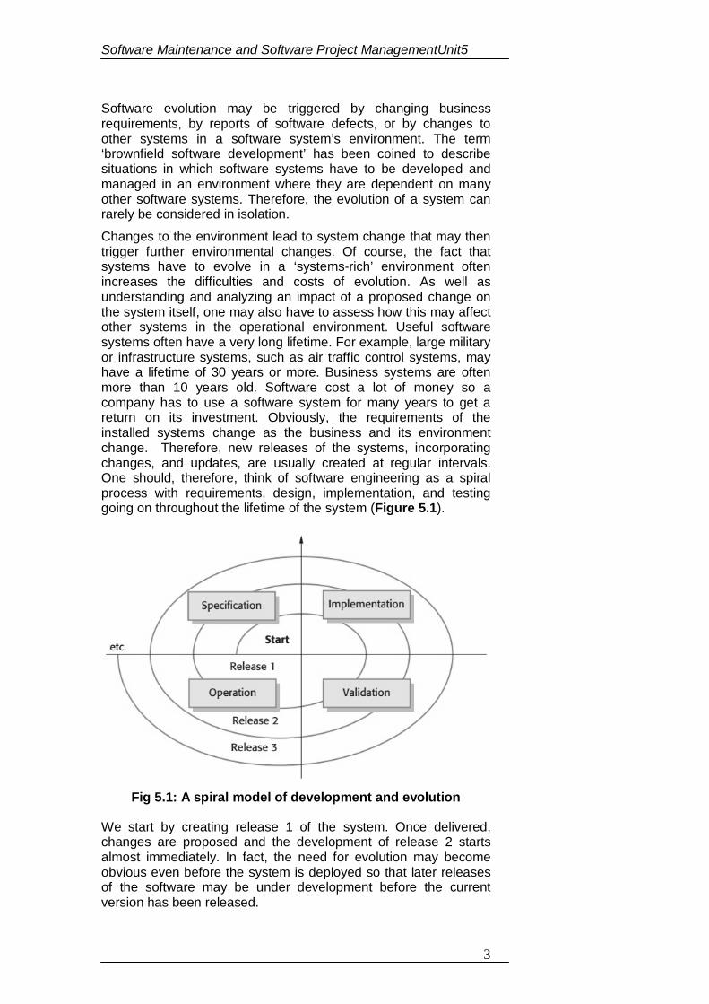
Software Maintenance and Software Project ManagementUnit5
3
Software evolution may be triggered by changing business requirements, by reports of software defects, or by changes to other systems in a software system’s environment. The term ‘brownfield software development’ has been coined to describe situations in which software systems have to be developed and managed in an environment where they are dependent on many other software systems. Therefore, the evolution of a system can rarely be considered in isolation. Changes to the environment lead to system change that may then trigger further environmental changes. Of course, the fact that systems have to evolve in a ‘systems-rich’ environment often increases the difficulties and costs of evolution. As well as understanding and analyzing an impact of a proposed change on the system itself, one may also have to assess how this may affect other systems in the operational environment. Useful software systems often have a very long lifetime. For example, large military or infrastructure systems, such as air traffic control systems, may have a lifetime of 30 years or more. Business systems are often more than 10 years old. Software cost a lot of money so a company has to use a software system for many years to get a return on its investment. Obviously, the requirements of the installed systems change as the business and its environment change. Therefore, new releases of the systems, incorporating changes, and updates, are usually created at regular intervals. One should, therefore, think of software engineering as a spiral process with requirements, design, implementation, and testing going on throughout the lifetime of the system (Figure 5.1).
Fig 5.1: A spiral model of development and evolution
We start by creating release 1 of the system. Once delivered, changes are proposed and the development of release 2 starts almost immediately. In fact, the need for evolution may become obvious even before the system is deployed so that later releases of the software may be under development before the current version has been released.
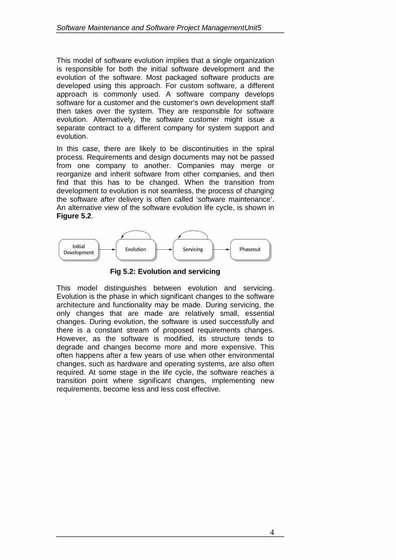
Software Maintenance and Software Project ManagementUnit5
4
This model of software evolution implies that a single organization is responsible for both the initial software development and the evolution of the software. Most packaged software products are developed using this approach. For custom software, a different approach is commonly used. A software company develops software for a customer and the customer’s own development staff then takes over the system. They are responsible for software evolution. Alternatively, the software customer might issue a separate contract to a different company for system support and evolution. In this case, there are likely to be discontinuities in the spiral process. Requirements and design documents may not be passed from one company to another. Companies may merge or reorganize and inherit software from other companies, and then find that this has to be changed. When the transition from development to evolution is not seamless, the process of changing the software after delivery is often called ‘software maintenance’. An alternative view of the software evolution life cycle, is shown in Figure 5.2.
Fig 5.2: Evolution and servicing
This model distinguishes between evolution and servicing. Evolution is the phase in which significant changes to the software architecture and functionality may be made. During servicing, the only changes that are made are relatively small, essential changes. During evolution, the software is used successfully and there is a constant stream of proposed requirements changes. However, as the software is modified, its structure tends to degrade and changes become more and more expensive. This often happens after a few years of use when other environmental changes, such as hardware and operating systems, are also often required. At some stage in the life cycle, the software reaches a transition point where significant changes, implementing new requirements, become less and less cost effective.
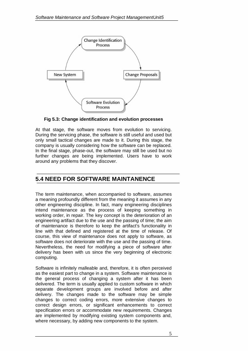
Software Maintenance and Software Project ManagementUnit5
5
Fig 5.3: Change identification and evolution processes
At that stage, the software moves from evolution to servicing. During the servicing phase, the software is still useful and used but only small tactical changes are made to it. During this stage, the company is usually considering how the software can be replaced. In the final stage, phase-out, the software may still be used but no further changes are being implemented. Users have to work around any problems that they discover.
5.4 NEED FOR SOFTWARE MAINTANENCE The term maintenance, when accompanied to software, assumes a meaning profoundly different from the meaning it assumes in any other engineering discipline. In fact, many engineering disciplines intend maintenance as the process of keeping something in working order, in repair. The key concept is the deterioration of an engineering artifact due to the use and the passing of time; the aim of maintenance is therefore to keep the artifact’s functionality in line with that defined and registered at the time of release. Of course, this view of maintenance does not apply to software, as software does not deteriorate with the use and the passing of time. Nevertheless, the need for modifying a piece of software after delivery has been with us since the very beginning of electronic computing. Software is infinitely malleable and, therefore, it is often perceived as the easiest part to change in a system. Software maintenance is the general process of changing a system after it has been delivered. The term is usually applied to custom software in which separate development groups are involved before and after delivery. The changes made to the software may be simple changes to correct coding errors, more extensive changes to correct design errors, or significant enhancements to correct specification errors or accommodate new requirements. Changes are implemented by modifying existing system components and, where necessary, by adding new components to the system.
Software Maintenance and Software Project ManagementUnit5
6
Software maintenance is a very broad activity often defined as including all work made on a software system after it becomes operational. This covers the correction of errors, the enhancement, deletion and addition of capabilities, the adaptation to changes in data requirements and operation environments, the improvement of performance, usability, or any other quality attribute. The IEEE definition is as follows: “Software maintenance is the process of modifying a software system or component after delivery to correct faults, improve performances or other attributes, or adapt to a changed environment.” This definition reflects the common view that software maintenance is a post-delivery activity: it starts when a system is released to the customer or user and encompasses all activities that keep the system operational and meet the user’s needs. This view is well summarized by the classical waterfall models of the software life cycle, which generally comprise a final phase of operation and maintenance. Several authors disagree with this view and affirm that software maintenance should start well before a system becomes operational. Schneidewind states that the myopic view that maintenance is strictly a post-delivery activity is one of the reasons that make maintenance hard. Osborne and Chikofsky affirm that it is essential to adopt a life cycle approach to managing and changing software systems, one which looks at all aspects of the development process with an eye toward maintenance. Pigoski captures the needs to begin maintenance when development begins in a new definition: “Software maintenance is the totality of activities required to provide cost-effective support to a software system. Activities are performed during the pre-delivery stage as well as the post-delivery stage. Pre-delivery activities include planning for post-delivery operations, supportability, and logistics determination. Post-delivery activities include software modification, training, and operating a help desk.” This definition is consistent with the approach to software maintenance taken by ISO in its standard on software life cycle processes. It definitively dispels the image that software maintenance is all about fixing bugs or mistakes. 5.5 CATEGORIES OF MAINTANANCE Across the 70’s and the 80’s, several authors have studied the maintenance phenomenon with the aim of identifying the reasons that originate the needs for changes and their relative frequencies and costs. As a result of these studies, several classifications of maintenance activities have been defined; these classifications help to better understand the great significance of maintenance and its implications on the cost and the quality of the systems in use. Dividing the maintenance effort into categories has first made evident that software maintenance is more than correcting errors. Ideally, maintenance operations should not degrade the reliability and the structure of the subject system, neither should they degrade its maintainability otherwise future changes will be progressively more difficult and costly to implement. Unfortunately,
Software Maintenance and Software Project ManagementUnit5
7
this is not the case for real-world maintenance, which often induces a phenomenon of aging of the subject system. Preventive maintenance – Computer software deteriorates due to change, and because of this, preventive maintenance must be conducted to enable the software to serve the needs of its end users. In essence, preventive maintenance makes changes to computer programs so that they can be more easily corrected, adapted, and enhanced. Corrective maintenance – Corrective maintenance includes all the changes made to remove actual faults in the software, and it can be called a reactive modification of a software product performed after delivery to correct discovered faults. Corrective maintenance changes the software to correct defects. ‘Corrective maintenance’ is universally used to refer to maintenance for fault repair. Perfective maintenance – Perfective maintenance refers to changes that originate from user requests; examples include inserting, deleting, extending, and modifying functions, rewriting documentation, improving performances, or improving ease of use. Perfective maintenance sometimes means perfecting the software by implementing new requirements; in other cases it means maintaining the functionality of the system but improving its structure and its performance. As software is used, the customer/user will recognize additional functions that will provide benefit. Perfective maintenance extends the software beyond its original functional requirements.
5.6 COST OF MAINTENANCE
However one decides to categorize the maintenance effort, it is still clear that software maintenance accounts for a huge amount of the overall software budget for an information system organization. Since 1972, software maintenance was characterized as an “iceberg” to highlight the enormous mass of potential problems and costs that lie under the surface. Although figures vary, several surveys indicate that software maintenance consumes 60% to 80% of the total life cycle costs; these surveys also report that maintenance costs are largely due to enhancements (often 75–80%), rather than corrections. Several technical and managerial problems contribute to the costs of software maintenance. Among the most challenging problems of software maintenance are: program comprehension, impact analysis, and regression testing. Whenever a change is made to a piece of software, it is important that the maintainer gains a complete understanding of the structure, behavior and functionality of the system being modified. It is on the basis of this understanding that modification proposals to accomplish the maintenance objectives can be generated. As a
Software Maintenance and Software Project ManagementUnit5
8
consequence, maintainers spend a large amount of their time reading the code and the accompanying documentation to comprehend its logic, purpose, and structure. Available estimates indicate that the percentage of maintenance time consumed on program comprehension ranges from 50% up to 90%. Program comprehension is frequently compounded because the maintainer is rarely the author of the code (or a significant period of time has elapsed between development and maintenance) and a complete, up-to-date documentation is even more rarely available. One of the major challenges in software maintenance is to determine the effects of a proposed modification on the rest of the system. Impact analysis is the activity of assessing the potential effects of a change with the aim of minimizing unexpected side effects. The task involves assessing the appropriateness of a proposed modification and evaluating the risks associated with its implementation, including estimates of the effects on resources, effort and scheduling. It also involves the identification of the system’s parts that need to be modified as a consequence of the proposed modification. Of note is that although impact analysis plays a central role within the maintenance process, there is no agreement about its definition and the IEEE Glossary of Software Engineering Terminology does not give a definition of impact analysis. Once a change has been implemented, the software system has to be retested to gain confidence that it will perform according to the (possibly modified) specification. The process of testing a system after it has been modified is called regression testing. The aim of regression testing is twofold: to establish confidence that changes are correct and to ensure that unchanged portions of the system have not been affected. Regression testing differs from the testing performed during development because a set of test cases may be available for reuse. Indeed, changes made during a maintenance process are usually small (major rewriting are a rather rare event in the history of a system) and, therefore, the simple approach of executing all test cases after each change may be excessively costly. Alternatively, several strategies for selective regression testing are available that attempt to select a subset of the available test cases without affecting test effectiveness. Most problems that are associated with software maintenance can be traced to deficiencies of the software development process. Sneidewind affirms that “the main problem in doing maintenance is that we cannot do maintenance on a system which was not designed for maintenance”. However, there are also essential difficulties, i.e. intrinsic characteristics of software and its production process that contribute to make software maintenance an unequalled challenge. Brooks identifies complexity, conformity, changeability, and invisibility as four essential difficulties of software and Rajlich adds discontinuity to this list.
Software Maintenance and Software Project ManagementUnit5
9
1. Fill in the blanks: (a) Software evolution may be triggered by changing business
___________. (b) Software __________ is the general process of changing a
system after it has been delivered. (c) Maintenance operations should not degrade the
__________ and the _________ of the subject system. (d) ___________ maintenance is universally used to refer to
maintenance for fault repair. (e) Several ________ and _______ problems contribute to the
costs of software maintenance
5.7 SOFTWARE RE-ENGINEERING
The process of system evolution involves understanding the program that has to be changed and then implementing these changes. However, many systems, especially older legacy systems, are difficult to understand and change. The programs may have been optimized for performance or space utilization at the expense of understandability, or, over time, the initial program structure may have been corrupted by a series of changes. To make legacy software systems easier to maintain, one can reengineer these systems to improve their structure and understandability. Reengineering may involve re-documenting the system, refactoring the system architecture, translating programs to a modern programming language, and modifying and updating the structure and values of the system’s data. Software re-engineering is a complex process that re-engineering tools can only support, not completely automate. There is a good deal of human intervention with any software re-engineering project. Re-engineering tools can provide help in moving a system to a new maintenance environment, for example one based on a repository, but they cannot define such an environment nor the optimal path along which to migrate the system to it. These are activities that only human beings can perform. Another problem that re-engineering tools only marginally tackle is the creation of an adequate test-bed to prove that the end product of re-engineering is fully equivalent to the original system. This still involves much hand-checking, partially because very rarely an application is re-engineered without existing functions being changed and new functions being added. Finally, re-engineering tools often fail to
CHECK YOUR PROGRESS
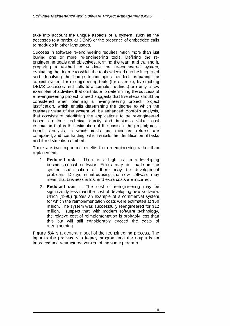
Software Maintenance and Software Project ManagementUnit5
10
take into account the unique aspects of a system, such as the accesses to a particular DBMS or the presence of embedded calls to modules in other languages. Success in software re-engineering requires much more than just buying one or more re-engineering tools. Defining the re-engineering goals and objectives, forming the team and training it, preparing a testbed to validate the re-engineered system, evaluating the degree to which the tools selected can be integrated and identifying the bridge technologies needed, preparing the subject system for re-engineering tools (for example, by stubbing DBMS accesses and calls to assembler routines) are only a few examples of activities that contribute to determining the success of a re-engineering project. Sneed suggests that five steps should be considered when planning a re-engineering project: project justification, which entails determining the degree to which the business value of the system will be enhanced; portfolio analysis, that consists of prioritizing the applications to be re-engineered based on their technical quality and business value; cost estimation that is the estimation of the costs of the project; cost-benefit analysis, in which costs and expected returns are compared, and; contracting, which entails the identification of tasks and the distribution of effort. There are two important benefits from reengineering rather than replacement:
1. Reduced risk – There is a high risk in redeveloping business-critical software. Errors may be made in the system specification or there may be development problems. Delays in introducing the new software may mean that business is lost and extra costs are incurred.
2. Reduced cost – The cost of reengineering may be significantly less than the cost of developing new software. Ulrich (1990) quotes an example of a commercial system for which the reimplementation costs were estimated at $50 million. The system was successfully reengineered for $12 million. I suspect that, with modern software technology, the relative cost of reimplementation is probably less than this but will still considerably exceed the costs of reengineering.
Figure 5.4 is a general model of the reengineering process. The input to the process is a legacy program and the output is an improved and restructured version of the same program.
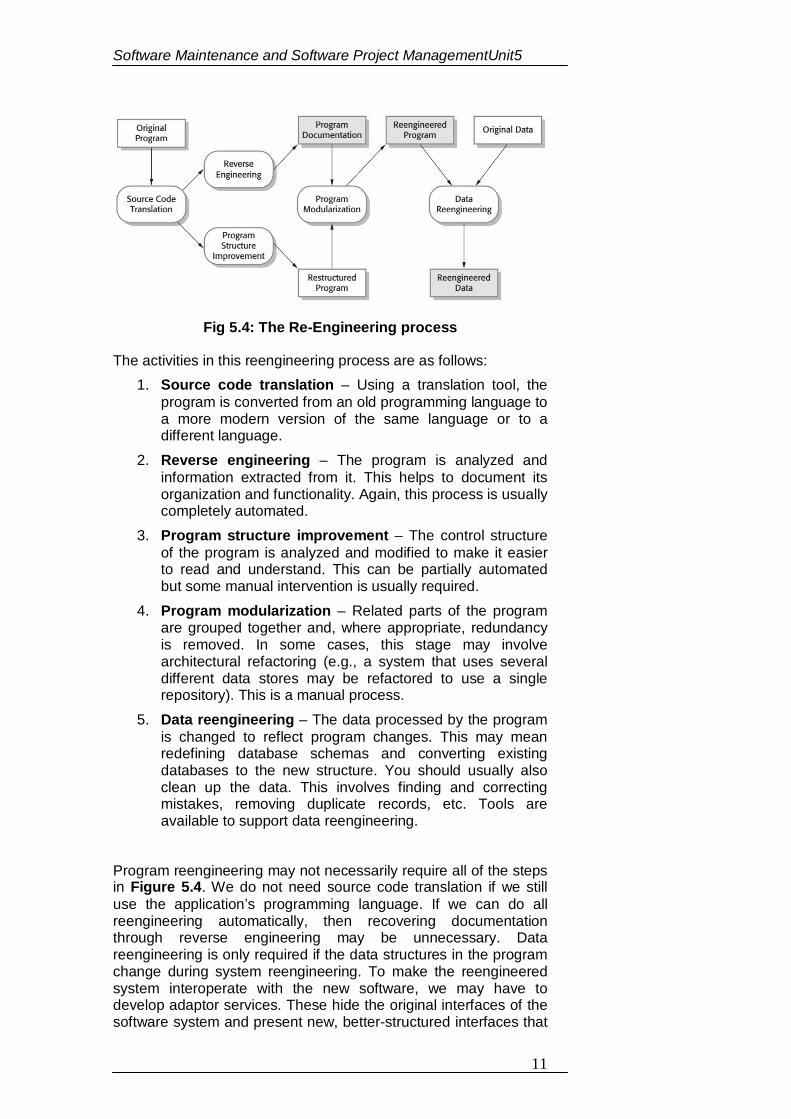
Software Maintenance and Software Project ManagementUnit5
11
Fig 5.4: The Re-Engineering process
The activities in this reengineering process are as follows: 1. Source code translation – Using a translation tool, the
program is converted from an old programming language to a more modern version of the same language or to a different language.
2. Reverse engineering – The program is analyzed and information extracted from it. This helps to document its organization and functionality. Again, this process is usually completely automated.
3. Program structure improvement – The control structure of the program is analyzed and modified to make it easier to read and understand. This can be partially automated but some manual intervention is usually required.
4. Program modularization – Related parts of the program are grouped together and, where appropriate, redundancy is removed. In some cases, this stage may involve architectural refactoring (e.g., a system that uses several different data stores may be refactored to use a single repository). This is a manual process.
5. Data reengineering – The data processed by the program is changed to reflect program changes. This may mean redefining database schemas and converting existing databases to the new structure. You should usually also clean up the data. This involves finding and correcting mistakes, removing duplicate records, etc. Tools are available to support data reengineering.
Program reengineering may not necessarily require all of the steps in Figure 5.4. We do not need source code translation if we still use the application’s programming language. If we can do all reengineering automatically, then recovering documentation through reverse engineering may be unnecessary. Data reengineering is only required if the data structures in the program change during system reengineering. To make the reengineered system interoperate with the new software, we may have to develop adaptor services. These hide the original interfaces of the software system and present new, better-structured interfaces that
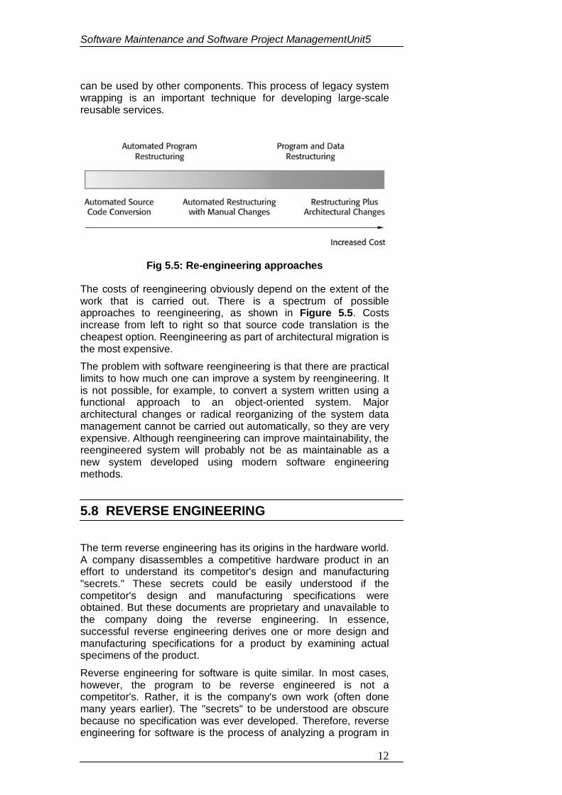
Software Maintenance and Software Project ManagementUnit5
12
can be used by other components. This process of legacy system wrapping is an important technique for developing large-scale reusable services.
Fig 5.5: Re-engineering approaches
The costs of reengineering obviously depend on the extent of the work that is carried out. There is a spectrum of possible approaches to reengineering, as shown in Figure 5.5. Costs increase from left to right so that source code translation is the cheapest option. Reengineering as part of architectural migration is the most expensive. The problem with software reengineering is that there are practical limits to how much one can improve a system by reengineering. It is not possible, for example, to convert a system written using a functional approach to an object-oriented system. Major architectural changes or radical reorganizing of the system data management cannot be carried out automatically, so they are very expensive. Although reengineering can improve maintainability, the reengineered system will probably not be as maintainable as a new system developed using modern software engineering methods.
5.8 REVERSE ENGINEERING The term reverse engineering has its origins in the hardware world. A company disassembles a competitive hardware product in an effort to understand its competitor's design and manufacturing "secrets." These secrets could be easily understood if the competitor's design and manufacturing specifications were obtained. But these documents are proprietary and unavailable to the company doing the reverse engineering. In essence, successful reverse engineering derives one or more design and manufacturing specifications for a product by examining actual specimens of the product. Reverse engineering for software is quite similar. In most cases, however, the program to be reverse engineered is not a competitor's. Rather, it is the company's own work (often done many years earlier). The "secrets" to be understood are obscure because no specification was ever developed. Therefore, reverse engineering for software is the process of analyzing a program in
Software Maintenance and Software Project ManagementUnit5
13
an effort to create a representation of the program at a higher level of abstraction than source code. Reverse engineering is a process of design recovery. Reverse engineering tools extract data, architectural, and procedural design information from an existing program. Reverse engineering has been defined as “the process of analyzing a subject system to identify the system’s components and their interrelationships and to create representations of the system in another form or at a higher level of abstraction”. Accordingly, reverse engineering is a process of examination, not a process of change, and therefore it does not involve changing the software under examination. Reverse engineering as a process is difficult to define in rigorous terms because it is a new and rapidly evolving field. Traditionally, reverse engineering has been viewed as a two-step process: information extraction and abstraction. Information extraction analyses the subject system artifacts – primarily the source code – to gather row data, whereas information abstraction creates user-oriented documents and views. Reverse engineering conjures an image of the "magic slot." We feed an unstructured, undocumented source listing into the slot and out the other end comes full documentation for the computer program. Unfortunately, the magic slot does not exist. Reverse engineering can extract design information from source code, but the abstraction level, the completeness of the documentation, the degree to which tools and a human analyst work together, and the directionality of the process are highly variable. The abstraction level of a reverse engineering process and the tools used to effect it refers to the sophistication of the design information that can be extracted from source code. Ideally, the abstraction level should be as high as possible. That is, the reverse engineering process should be capable of deriving procedural design representations (a low-level abstraction), program and data structure information (a somewhat higher level of abstraction), data and control flow models (a relatively high level of abstraction), and entity relationship models (a high level of abstraction). As the abstraction level increases, the software engineer is provided with information that will allow easier understanding of the program. The completeness of a reverse engineering process refers to the level of detail that is provided at an abstraction level. In most cases, the completeness decreases as the abstraction level increases. For example, given a source code listing, it is relatively easy to develop a complete procedural design representation. Simple data flow representations may also be derived, but it is far more difficult to develop a complete set of data flow diagrams or entity-relationship models. Completeness improves in direct proportion to the amount of analysis performed by the person doing reverse engineering. Interactivity refers to the degree to which the human is "integrated" with automated tools to create an effective reverse engineering process. In most cases, as the abstraction level increases, interactivity must increase or completeness will suffer. If the directionality of the reverse engineering process is one way, all information extracted from the source code is provided to the software engineer who can then use it during any maintenance
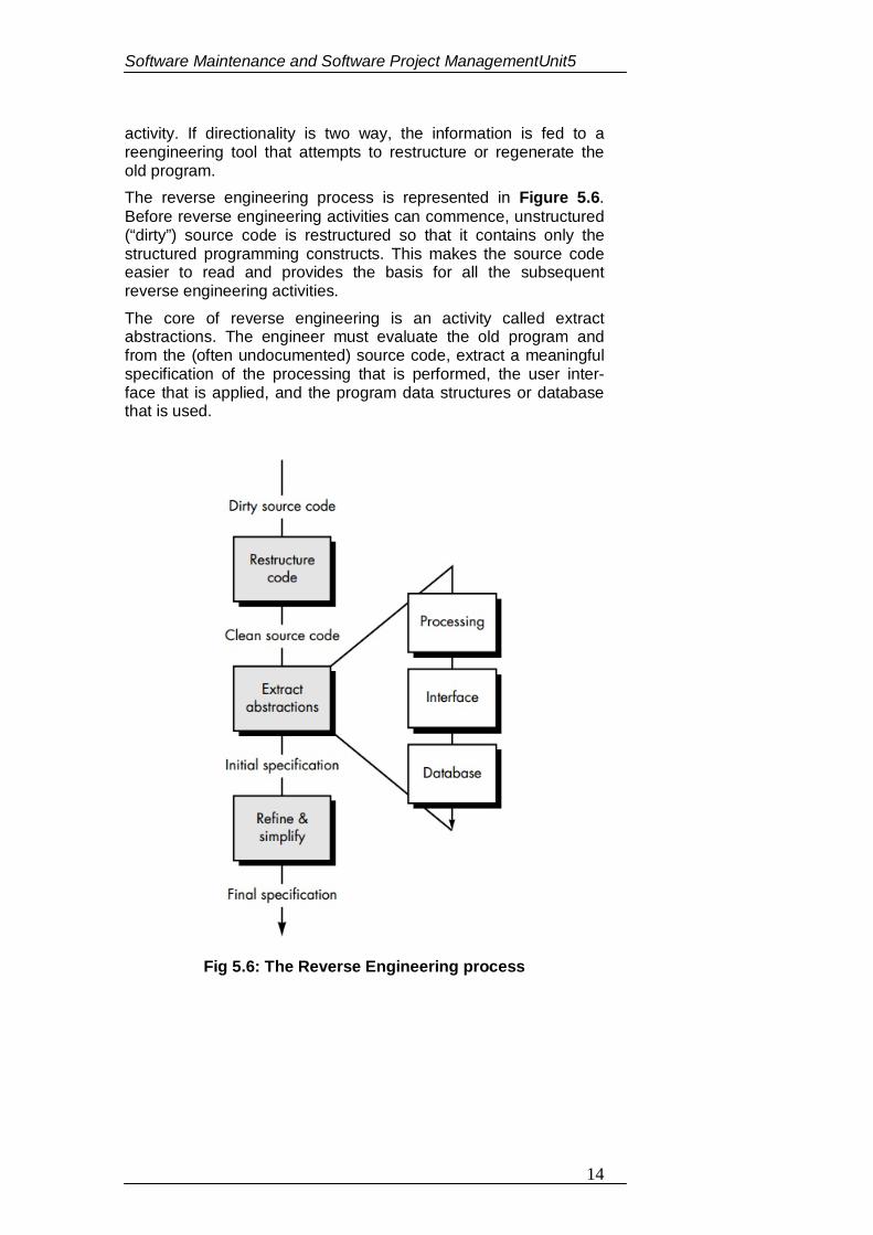
Software Maintenance and Software Project ManagementUnit5
14
activity. If directionality is two way, the information is fed to a reengineering tool that attempts to restructure or regenerate the old program. The reverse engineering process is represented in Figure 5.6. Before reverse engineering activities can commence, unstructured (“dirty”) source code is restructured so that it contains only the structured programming constructs. This makes the source code easier to read and provides the basis for all the subsequent reverse engineering activities. The core of reverse engineering is an activity called extract abstractions. The engineer must evaluate the old program and from the (often undocumented) source code, extract a meaningful specification of the processing that is performed, the user inter-face that is applied, and the program data structures or database that is used.
Fig 5.6: The Reverse Engineering process
Software Maintenance and Software Project ManagementUnit5
15
5.9 SOFTWARE CONFIGURATION MANAGEMENT ACTIVITIES
In software development, change happens all the time, so change management is absolutely essential. When a team of people are developing software, it has to be made sure that team members do not interfere with each other’s’ work. That is, if two people are working on a component, their changes have to be coordinated. Otherwise, one programmer may make changes and overwrite the other’s work. It also has to be ensured that everyone can access the most up-to-date versions of software components, otherwise developers may redo work that has already been done. When something goes wrong with a new version of a system, one has to be able to go back to a working version of the system or component. Configuration management is the name given to the general process of managing a changing software system. The aim of configuration management is to support the system integration process so that all developers can access the project code and documents in a controlled way, find out what changes have been made, and compile and link components to create a system. There are, therefore, three fundamental configuration management activities:
1. Version management, where support is provided to keep track of the different versions of software components. Version management systems include facilities to coordinate development by several programmers. They stop one developer from overwriting code that has been submitted to the system by someone else.
2. System integration, where support is provided to help developers define what versions of components are used to create each version of a system. This description is then used to build a system automatically by compiling and linking the required components.
3. Problem tracking, where support is provided to allow users to report bugs and other problems, and to allow all developers to see who is working on these problems and when they are fixed.
5.9.1 CHANGE CONTROL PROCESS
Change Control Process is a formal process used to ensure that changes to a product or system are introduced in a controlled and coordinated manner. It reduces the possibility that unnecessary changes will be introduced to a system without forethought, introducing faults into the system or undoing changes made by other users of software. The goals of a change control procedure usually include minimal disruption to services, reduction in back-
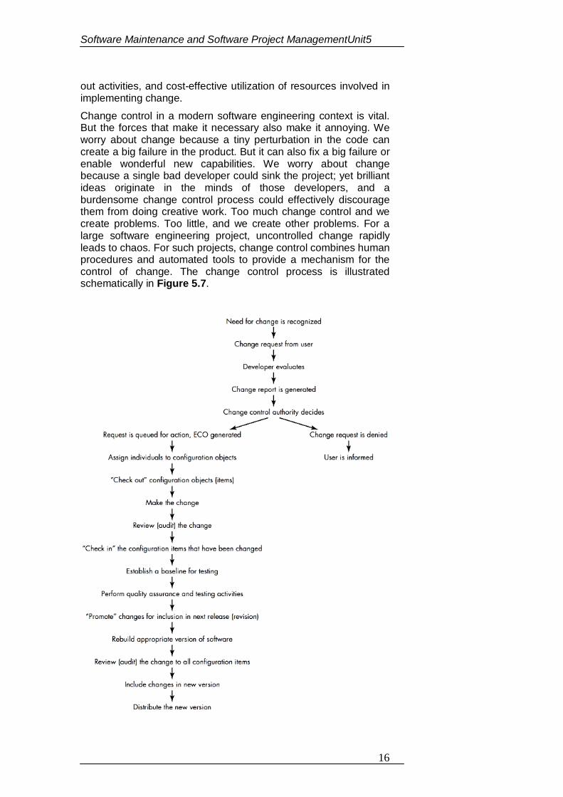
Software Maintenance and Software Project ManagementUnit5
16
out activities, and cost-effective utilization of resources involved in implementing change. Change control in a modern software engineering context is vital. But the forces that make it necessary also make it annoying. We worry about change because a tiny perturbation in the code can create a big failure in the product. But it can also fix a big failure or enable wonderful new capabilities. We worry about change because a single bad developer could sink the project; yet brilliant ideas originate in the minds of those developers, and a burdensome change control process could effectively discourage them from doing creative work. Too much change control and we create problems. Too little, and we create other problems. For a large software engineering project, uncontrolled change rapidly leads to chaos. For such projects, change control combines human procedures and automated tools to provide a mechanism for the control of change. The change control process is illustrated schematically in Figure 5.7.
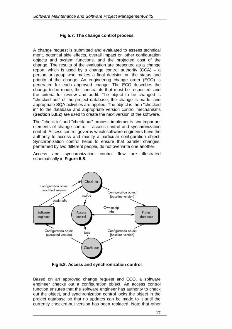
Software Maintenance and Software Project ManagementUnit5
17
Fig 5.7: The change control process A change request is submitted and evaluated to assess technical merit, potential side effects, overall impact on other configuration objects and system functions, and the projected cost of the change. The results of the evaluation are presented as a change report, which is used by a change control authority (CCA) – a person or group who makes a final decision on the status and priority of the change. An engineering change order (ECO) is generated for each approved change. The ECO describes the change to be made, the constraints that must be respected, and the criteria for review and audit. The object to be changed is "checked out" of the project database, the change is made, and appropriate SQA activities are applied. The object is then "checked in" to the database and appropriate version control mechanisms (Section 5.9.2) are used to create the next version of the software.
The "check-in" and "check-out" process implements two important elements of change control – access control and synchronization control. Access control governs which software engineers have the authority to access and modify a particular configuration object. Synchronization control helps to ensure that parallel changes, performed by two different people, do not overwrite one another. Access and synchronization control flow are illustrated schematically in Figure 5.8.
Fig 5.8: Access and synchronization control
Based on an approved change request and ECO, a software engineer checks out a configuration object. An access control function ensures that the software engineer has authority to check out the object, and synchronization control locks the object in the project database so that no updates can be made to it until the currently checked-out version has been replaced. Note that other
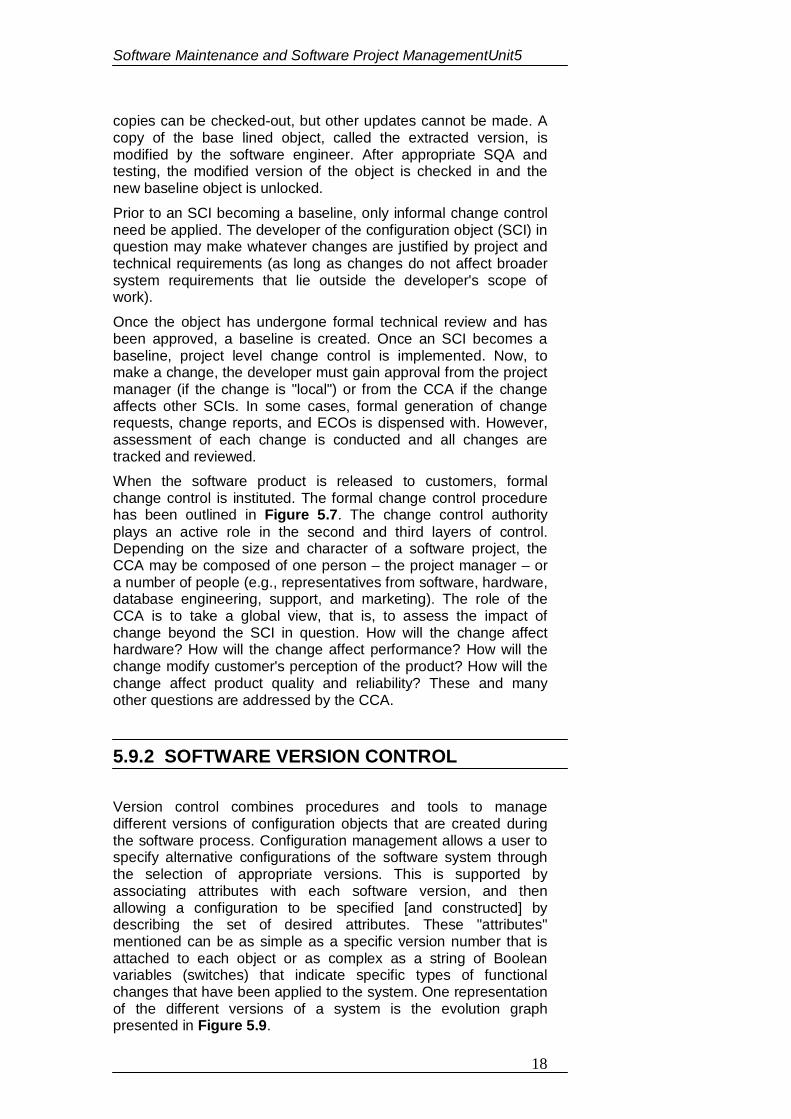
Software Maintenance and Software Project ManagementUnit5
18
copies can be checked-out, but other updates cannot be made. A copy of the base lined object, called the extracted version, is modified by the software engineer. After appropriate SQA and testing, the modified version of the object is checked in and the new baseline object is unlocked. Prior to an SCI becoming a baseline, only informal change control need be applied. The developer of the configuration object (SCI) in question may make whatever changes are justified by project and technical requirements (as long as changes do not affect broader system requirements that lie outside the developer's scope of work). Once the object has undergone formal technical review and has been approved, a baseline is created. Once an SCI becomes a baseline, project level change control is implemented. Now, to make a change, the developer must gain approval from the project manager (if the change is "local") or from the CCA if the change affects other SCIs. In some cases, formal generation of change requests, change reports, and ECOs is dispensed with. However, assessment of each change is conducted and all changes are tracked and reviewed. When the software product is released to customers, formal change control is instituted. The formal change control procedure has been outlined in Figure 5.7. The change control authority plays an active role in the second and third layers of control. Depending on the size and character of a software project, the CCA may be composed of one person – the project manager – or a number of people (e.g., representatives from software, hardware, database engineering, support, and marketing). The role of the CCA is to take a global view, that is, to assess the impact of change beyond the SCI in question. How will the change affect hardware? How will the change affect performance? How will the change modify customer's perception of the product? How will the change affect product quality and reliability? These and many other questions are addressed by the CCA.
5.9.2 SOFTWARE VERSION CONTROL
Version control combines procedures and tools to manage different versions of configuration objects that are created during the software process. Configuration management allows a user to specify alternative configurations of the software system through the selection of appropriate versions. This is supported by associating attributes with each software version, and then allowing a configuration to be specified [and constructed] by describing the set of desired attributes. These "attributes" mentioned can be as simple as a specific version number that is attached to each object or as complex as a string of Boolean variables (switches) that indicate specific types of functional changes that have been applied to the system. One representation of the different versions of a system is the evolution graph presented in Figure 5.9.
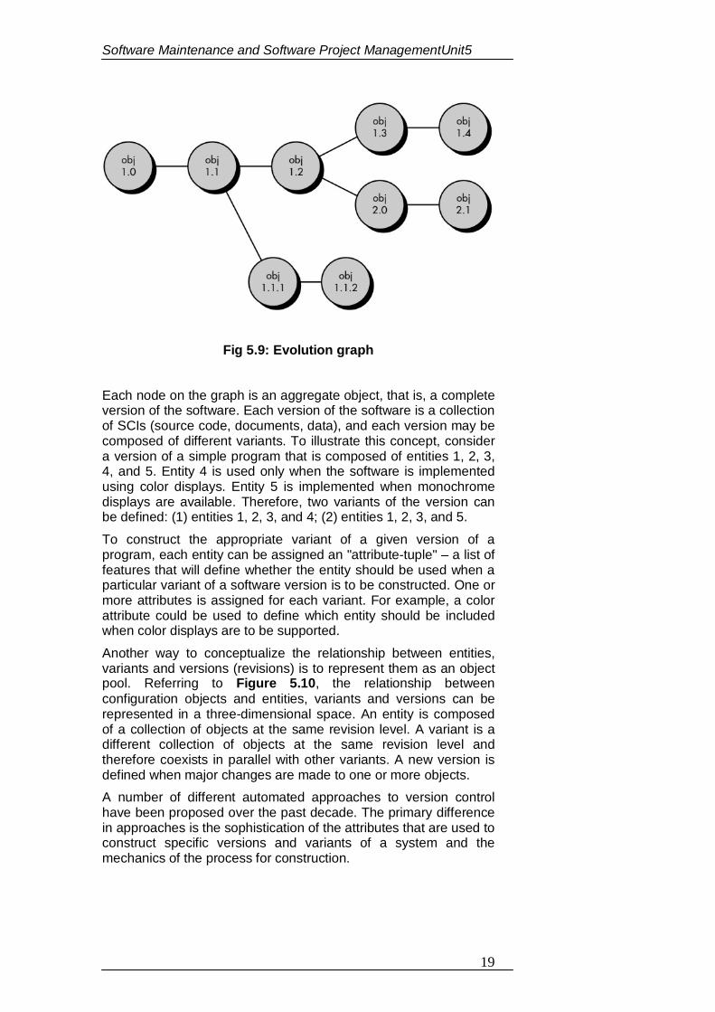
Software Maintenance and Software Project ManagementUnit5
19
Fig 5.9: Evolution graph Each node on the graph is an aggregate object, that is, a complete version of the software. Each version of the software is a collection of SCIs (source code, documents, data), and each version may be composed of different variants. To illustrate this concept, consider a version of a simple program that is composed of entities 1, 2, 3, 4, and 5. Entity 4 is used only when the software is implemented using color displays. Entity 5 is implemented when monochrome displays are available. Therefore, two variants of the version can be defined: (1) entities 1, 2, 3, and 4; (2) entities 1, 2, 3, and 5. To construct the appropriate variant of a given version of a program, each entity can be assigned an "attribute-tuple" – a list of features that will define whether the entity should be used when a particular variant of a software version is to be constructed. One or more attributes is assigned for each variant. For example, a color attribute could be used to define which entity should be included when color displays are to be supported. Another way to conceptualize the relationship between entities, variants and versions (revisions) is to represent them as an object pool. Referring to Figure 5.10, the relationship between configuration objects and entities, variants and versions can be represented in a three-dimensional space. An entity is composed of a collection of objects at the same revision level. A variant is a different collection of objects at the same revision level and therefore coexists in parallel with other variants. A new version is defined when major changes are made to one or more objects. A number of different automated approaches to version control have been proposed over the past decade. The primary difference in approaches is the sophistication of the attributes that are used to construct specific versions and variants of a system and the mechanics of the process for construction.
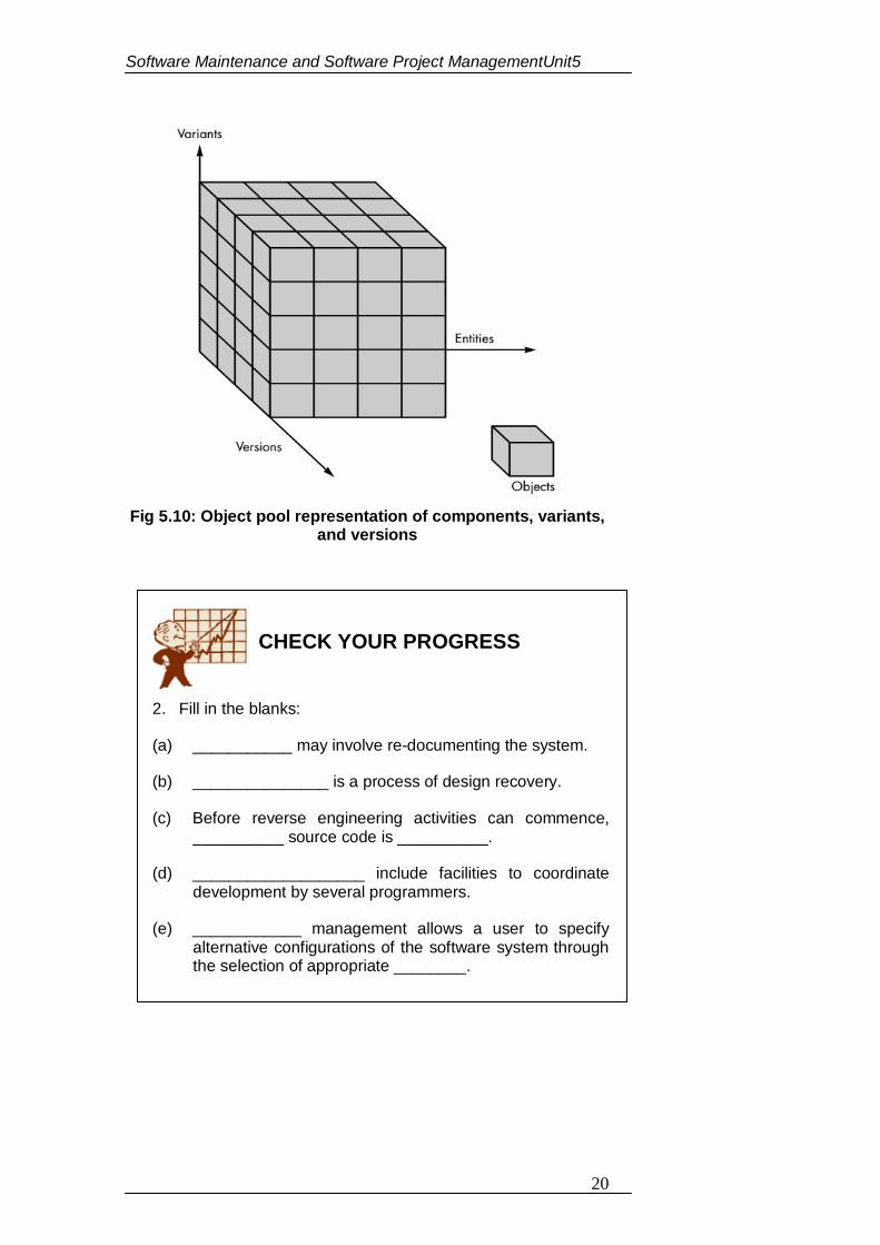
Software Maintenance and Software Project ManagementUnit5
20
Fig 5.10: Object pool representation of components, variants,
and versions
2. Fill in the blanks:
(a) ___________ may involve re-documenting the system.
(b) _______________ is a process of design recovery.
(c) Before reverse engineering activities can commence, __________ source code is __________.
(d) ___________________ include facilities to coordinate development by several programmers.
(e) ____________ management allows a user to specify alternative configurations of the software system through the selection of appropriate ________.
CHECK YOUR PROGRESS
Software Maintenance and Software Project ManagementUnit5
21
AN OVERVIEW OF CASE TOOLS Computer Aided Software Engineering (CASE) tools assist software engineering managers and practitioners in every activity associated with the software process. They automate project management activities; manage all work products produced throughout the process, and assist engineers in their analysis, design, coding and test work. CASE tools can be integrated within a sophisticated environment. Software engineering is difficult and so tools that reduce the amount of effort required to produce a work product or accomplish some project milestone have substantial benefit. But there is something that is even more important. Tools can provide new ways of looking at software engineering information – ways that improve the insight of the engineer doing the work. This leads to better decisions and higher software quality. CASE tools assist a software engineer in producing high-quality work products. In addition, the availability of automation allows the CASE user to produce additional customized work products that could not be easily or practically produced without tool support. CASE provides the software engineer with the ability to automate manual activities and to improve engineering insight. Like computer-aided engineering and design tools that are used by engineers in other disciplines, CASE tools help to ensure that quality is designed in before the product is built. Tools –
CASE tools are a class of software that automates many of the activities involved in various life cycle phases. For example, when establishing the functional requirements of a proposed application, prototyping tools can be used to develop graphic models of application screens to assist end users to visualize how an application will look after development. Subsequently, system designers can use automated design tools to transform the prototyped functional requirements into detailed design documents. Programmers can then use automated code generators to convert the design documents into code. Automated tools can be used collectively, as mentioned, or individually. For example, prototyping tools could be used to define application requirements that get passed to design technicians who convert the requirements into detailed designs in a traditional manner using flowcharts and narrative documents, without the assistance of automated design software. Categories of CASE Tools – On the basis of their activities, sometimes CASE tools are classified into the following categories: 1. Upper CASE tools 2. Lower CASE tools 3. Integrated CASE tools
Software Maintenance and Software Project ManagementUnit5
22
Upper CASE: Upper CASE tools mainly focus on the analysis and design phases of software development. They include tools for analysis modeling, reports and forms generation. Lower CASE: Lower CASE tools support implementation of system development. They include tools for coding, configuration management, etc. Integrated CASE Tools: Integrated CASE tools help in providing linkages between the lower and upper CASE tools. Thus creating a cohesive environment for software development where programming by lower CASE tools may automatically be generated for the design that has been developed in an upper CASE tool. Need of CASE Tools –
The software development process is expensive and as the projects become more complex in nature, the project implementations become more demanding and expensive. The CASE tools provide the integrated homogenous environment for the development of complex projects. They allow creating a shared repository of information that can be utilized to minimize the software development time. The CASE tools also provide the environment for monitoring and controlling projects such that team leaders are able to manage the complex projects.
Specifically, the CASE tools are normally deployed to –
Reduce the cost as they automate many repetitive manual tasks.
Reduce development time of the project as they support standardization and avoid repetition and reuse.
Develop better quality complex projects as they provide greater consistency and coordination.
Create good quality documentation.
Create systems that are maintainable because of proper control of configuration item that support traceability requirements.
Characteristics of a successful CASE Tool – A CASE tool must have the following characteristics in order to be used efficiently:
A standard methodology: A CASE tool must support a standard software development methodology and standard modeling techniques. In the present scenario most of the CASE tools are moving towards UML.
Flexibility: Flexibility in use of editors and other tools. The CASE tool must offer flexibility and the choice for the user of editors’ development environments.
Strong Integration: The CASE tools should be integrated to support all the stages. This implies that if a change is made at any stage, for example, in the model, it should get
Software Maintenance and Software Project ManagementUnit5
23
reflected in the code documentation and all related design and other documents, thus providing a cohesive environment for software development.
Integration with testing software: The CASE tools must provide interfaces for automatic testing tools that take care of regression and other kinds of testing software under the changing requirements.
Support for reverse engineering: A CASE tools must be able to generate complex models from already generated code.
On-line help: The CASE tools provide an online tutorial.
5.11 PARAMETER ESTIMATION (cost, effort, schedule) Software project estimation is the process of estimating various resources required for the completion of a project. Effective software project estimation is an important activity in any software development project. Underestimating software projects and understaffing it often leads to low quality deliverables, and the project misses the target deadline leading to customer dissatisfaction and loss of credibility to the company. On the other hand, overstaffing a project without proper control will increase the cost of the project and reduce the competitiveness of the company. Software project estimation mainly encompasses the following activities:
1. Estimating the size of the project – There are many procedures available for estimating the size of a project, which are based on quantitative approaches, such as estimating lines of code or estimating the functionality requirements of the project called function points.
2. Estimating efforts based on person-months or person-hours – Person-month is an estimate of the personal resources required for the project.
3. Estimating Schedule in calendar Days/Months/Year based on total person-months required and manpower allocated to the project – The duration in calendar month = total person-months / total manpower allocated.
4. Estimating total cost of the project depending on the above and other resources – In a commercial and competitive environment, software project estimation is crucial for managerial decision making. Table 5.1 gives the relationship between various management functions and software metrics/indicators. Project estimation and tracking helps to plan and predict future projects and provide baseline support for project management and supports decision-making.
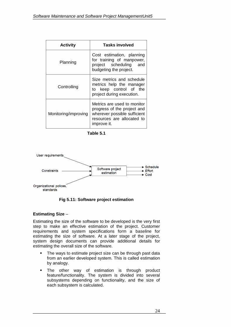
Software Maintenance and Software Project ManagementUnit5
24
Activity Tasks involved
Planning
Cost estimation, planning for training of manpower, project scheduling and budgeting the project.
Controlling
Size metrics and schedule metrics help the manager to keep control of the project during execution.
Monitoring/improving
Metrics are used to monitor progress of the project and wherever possible sufficient resources are allocated to improve it.
Table 5.1
Fig 5.11: Software project estimation Estimating Size –
Estimating the size of the software to be developed is the very first step to make an effective estimation of the project. Customer requirements and system specifications form a baseline for estimating the size of software. At a later stage of the project, system design documents can provide additional details for estimating the overall size of the software. The ways to estimate project size can be through past data
from an earlier developed system. This is called estimation by analogy.
The other way of estimation is through product feature/functionality. The system is divided into several subsystems depending on functionality, and the size of each subsystem is calculated.
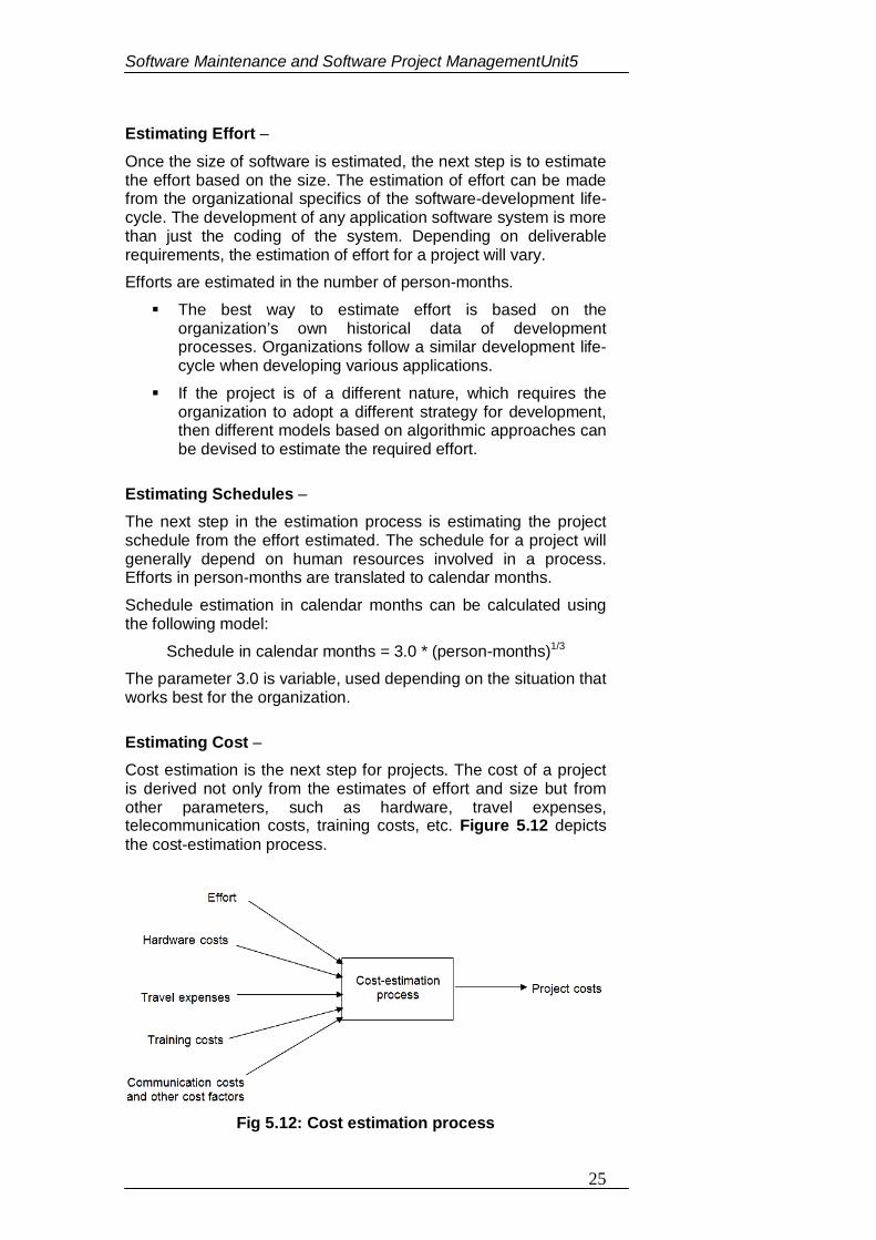
Software Maintenance and Software Project ManagementUnit5
25
Estimating Effort –
Once the size of software is estimated, the next step is to estimate the effort based on the size. The estimation of effort can be made from the organizational specifics of the software-development life-cycle. The development of any application software system is more than just the coding of the system. Depending on deliverable requirements, the estimation of effort for a project will vary. Efforts are estimated in the number of person-months. The best way to estimate effort is based on the
organization’s own historical data of development processes. Organizations follow a similar development life-cycle when developing various applications.
If the project is of a different nature, which requires the organization to adopt a different strategy for development, then different models based on algorithmic approaches can be devised to estimate the required effort.
Estimating Schedules – The next step in the estimation process is estimating the project schedule from the effort estimated. The schedule for a project will generally depend on human resources involved in a process. Efforts in person-months are translated to calendar months. Schedule estimation in calendar months can be calculated using the following model:
Schedule in calendar months = 3.0 * (person-months)1/3 The parameter 3.0 is variable, used depending on the situation that works best for the organization.
Estimating Cost – Cost estimation is the next step for projects. The cost of a project is derived not only from the estimates of effort and size but from other parameters, such as hardware, travel expenses, telecommunication costs, training costs, etc. Figure 5.12 depicts the cost-estimation process.
Fig 5.12: Cost estimation process
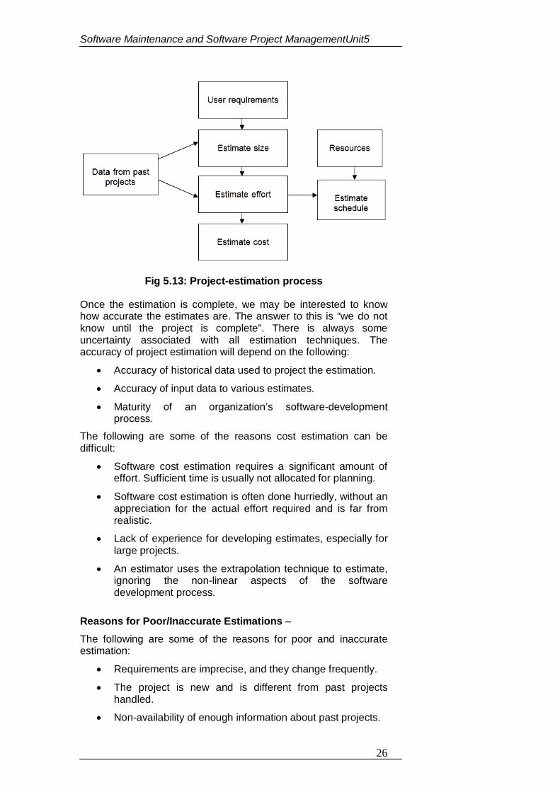
Software Maintenance and Software Project ManagementUnit5
26
Fig 5.13: Project-estimation process
Once the estimation is complete, we may be interested to know how accurate the estimates are. The answer to this is “we do not know until the project is complete”. There is always some uncertainty associated with all estimation techniques. The accuracy of project estimation will depend on the following:
Accuracy of historical data used to project the estimation.
Accuracy of input data to various estimates.
Maturity of an organization’s software-development process.
The following are some of the reasons cost estimation can be difficult:
Software cost estimation requires a significant amount of effort. Sufficient time is usually not allocated for planning.
Software cost estimation is often done hurriedly, without an appreciation for the actual effort required and is far from realistic.
Lack of experience for developing estimates, especially for large projects.
An estimator uses the extrapolation technique to estimate, ignoring the non-linear aspects of the software development process.
Reasons for Poor/Inaccurate Estimations –
The following are some of the reasons for poor and inaccurate estimation:
Requirements are imprecise, and they change frequently.
The project is new and is different from past projects handled.
Non-availability of enough information about past projects.
Software Maintenance and Software Project ManagementUnit5
27
Estimates are forced to be based on available resources.
Cost and time tradeoffs. If we elongate the project, we can reduce overall costs. Usually, customers and management do not like long project durations. There is always the shortest possible duration for a project, but it comes at a cost. The following are some of the problems associated with estimates:
Estimating size is often skipped and a schedule is estimated, which is of more relevance to management.
Estimating size is perhaps the most difficult step, which has a bearing on all other estimates.
Let us not forget that even good estimates are only projections and subject to various risks.
Organizations often give less importance to collection and analysis of historical data of past development projects. Historical data is the best input to estimate a new project.
Project managers often underestimate the schedule because management and customers often hesitate to accept a prudent realistic schedule.
5.12 CONSTRUCTIVE COST MODEL (COCOMO)
The Constructive Cost Model (COCOMO) is an algorithmic software cost estimation model developed by Barry W. Boehm. The model uses a basic regression formula with parameters that are derived from historical project data and current as well as future project characteristics.
COCOMO was first published in Boehm's 1981 book Software Engineering Economics as a model for estimating effort, cost, and schedule for software projects. It drew on a study of 63 projects at TRW Aerospace where Boehm was Director of Software Research and Technology. The study examined projects ranging in size from 2,000 to 100,000 lines of code, and programming languages ranging from assembly to PL/I. These projects were based on the waterfall model of software development which was the prevalent software development process in 1981.
COCOMO consists of a hierarchy of three increasingly detailed and accurate forms. The first level, Basic COCOMO is good for quick, early, rough order of magnitude estimates of software costs, but its accuracy is limited due to its lack of factors to account for difference in project attributes (Cost Drivers). Intermediate COCOMO takes these Cost Drivers into account and Detailed COCOMO additionally accounts for the influence of individual project phases.
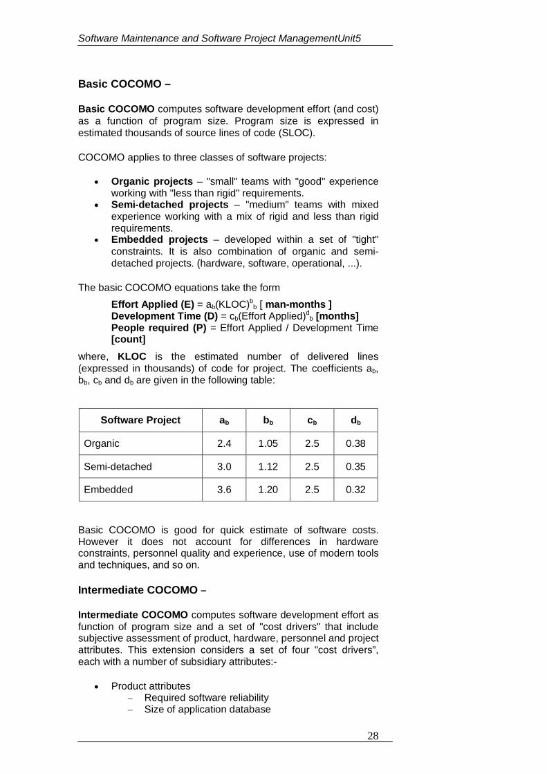
Software Maintenance and Software Project ManagementUnit5
28
Basic COCOMO –
Basic COCOMO computes software development effort (and cost) as a function of program size. Program size is expressed in estimated thousands of source lines of code (SLOC).
COCOMO applies to three classes of software projects:
Organic projects – "small" teams with "good" experience working with "less than rigid" requirements.
Semi-detached projects – "medium" teams with mixed experience working with a mix of rigid and less than rigid requirements.
Embedded projects – developed within a set of "tight" constraints. It is also combination of organic and semi-detached projects. (hardware, software, operational, ...).
The basic COCOMO equations take the form
Effort Applied (E) = ab(KLOC)bb [ man-months ]
Development Time (D) = cb(Effort Applied)db [months]
People required (P) = Effort Applied / Development Time [count]
where, KLOC is the estimated number of delivered lines (expressed in thousands) of code for project. The coefficients ab, bb, cb and db are given in the following table:
Software Project ab bb cb db
Organic 2.4 1.05 2.5 0.38
Semi-detached 3.0 1.12 2.5 0.35
Embedded 3.6 1.20 2.5 0.32
Basic COCOMO is good for quick estimate of software costs. However it does not account for differences in hardware constraints, personnel quality and experience, use of modern tools and techniques, and so on.
Intermediate COCOMO –
Intermediate COCOMO computes software development effort as function of program size and a set of "cost drivers" that include subjective assessment of product, hardware, personnel and project attributes. This extension considers a set of four "cost drivers”, each with a number of subsidiary attributes:-
Product attributes Required software reliability Size of application database
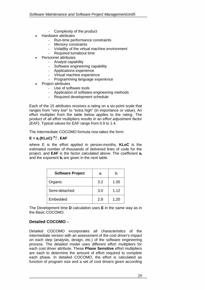
Software Maintenance and Software Project ManagementUnit5
29
Complexity of the product Hardware attributes
Run-time performance constraints Memory constraints Volatility of the virtual machine environment Required turnabout time
Personnel attributes Analyst capability Software engineering capability Applications experience Virtual machine experience Programming language experience
Project attributes Use of software tools Application of software engineering methods Required development schedule
Each of the 15 attributes receives a rating on a six-point scale that ranges from "very low" to "extra high" (in importance or value). An effort multiplier from the table below applies to the rating. The product of all effort multipliers results in an effort adjustment factor (EAF). Typical values for EAF range from 0.9 to 1.4.
The Intermediate COCOMO formula now takes the form: E = ai (KLoC) (bi
) . EAF where E is the effort applied in person-months, KLoC is the estimated number of thousands of delivered lines of code for the project, and EAF is the factor calculated above. The coefficient ai and the exponent bi are given in the next table.
Software Project ai bi
Organic 3.2 1.05
Semi-detached 3.0 1.12
Embedded 2.8 1.20
The Development time D calculation uses E in the same way as in the Basic COCOMO.
Detailed COCOMO –
Detailed COCOMO incorporates all characteristics of the intermediate version with an assessment of the cost driver's impact on each step (analysis, design, etc.) of the software engineering process. The detailed model uses different effort multipliers for each cost driver attribute. These Phase Sensitive effort multipliers are each to determine the amount of effort required to complete each phase. In detailed COCOMO, the effort is calculated as function of program size and a set of cost drivers given according
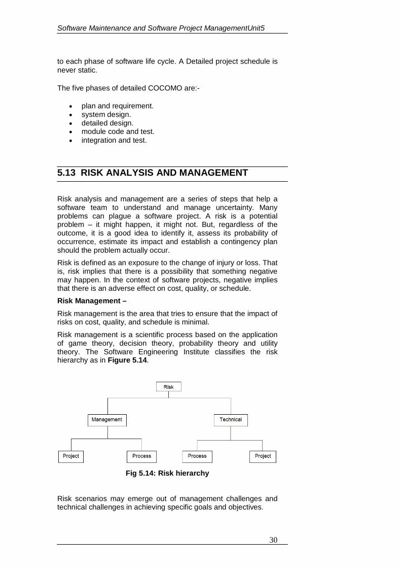
Software Maintenance and Software Project ManagementUnit5
30
to each phase of software life cycle. A Detailed project schedule is never static.
The five phases of detailed COCOMO are:-
plan and requirement. system design. detailed design. module code and test. integration and test.
5.13 RISK ANALYSIS AND MANAGEMENT Risk analysis and management are a series of steps that help a software team to understand and manage uncertainty. Many problems can plague a software project. A risk is a potential problem – it might happen, it might not. But, regardless of the outcome, it is a good idea to identify it, assess its probability of occurrence, estimate its impact and establish a contingency plan should the problem actually occur. Risk is defined as an exposure to the change of injury or loss. That is, risk implies that there is a possibility that something negative may happen. In the context of software projects, negative implies that there is an adverse effect on cost, quality, or schedule. Risk Management – Risk management is the area that tries to ensure that the impact of risks on cost, quality, and schedule is minimal. Risk management is a scientific process based on the application of game theory, decision theory, probability theory and utility theory. The Software Engineering Institute classifies the risk hierarchy as in Figure 5.14.
Fig 5.14: Risk hierarchy
Risk scenarios may emerge out of management challenges and technical challenges in achieving specific goals and objectives.
Software Maintenance and Software Project ManagementUnit5
31
Risk management must be performed regularly throughout the achievement life-cycle. Risks are dynamic, as they change over time. Risk management should not be treated as an activity outside the main process of achievement. Risk is managed best when risk management is implemented as a mainstream function in the software development and goal achievement process.
Management of Risks – Risk management plays an important role in ensuring that the software product is error-free. Firstly, risk management takes care that the risk is avoided, and if it is not avoidable, then the risk is detected, controlled and finally recovered.
Risk management categories –
A priority is given to risk and the highest priority risk is handled first. Various factors of the risk include who are the involved team members, what hardware and software items are needed, where, when and why. The risk manager does scheduling of risks. Risk management can be further categorized as follows:
1. Risk Avoidance
Risk anticipation
Risk tools 2. Risk detection
Risk analysis
Risk category
Risk prioritization 3. Risk Control
Risk pending
Risk resolution
Risk not solvable 4. Risk recovery
Full
Partial
Extra/alternate feature
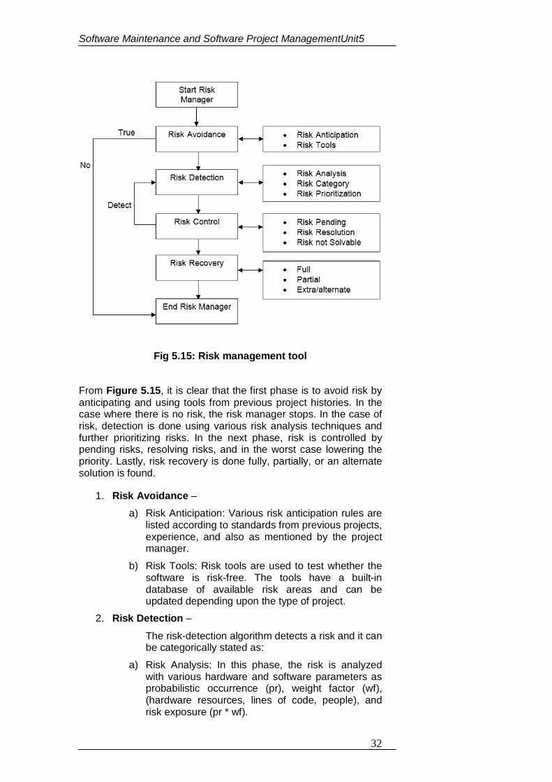
Software Maintenance and Software Project ManagementUnit5
32
Fig 5.15: Risk management tool From Figure 5.15, it is clear that the first phase is to avoid risk by anticipating and using tools from previous project histories. In the case where there is no risk, the risk manager stops. In the case of risk, detection is done using various risk analysis techniques and further prioritizing risks. In the next phase, risk is controlled by pending risks, resolving risks, and in the worst case lowering the priority. Lastly, risk recovery is done fully, partially, or an alternate solution is found.
1. Risk Avoidance – a) Risk Anticipation: Various risk anticipation rules are
listed according to standards from previous projects, experience, and also as mentioned by the project manager.
b) Risk Tools: Risk tools are used to test whether the software is risk-free. The tools have a built-in database of available risk areas and can be updated depending upon the type of project.
2. Risk Detection –
The risk-detection algorithm detects a risk and it can be categorically stated as:
a) Risk Analysis: In this phase, the risk is analyzed with various hardware and software parameters as probabilistic occurrence (pr), weight factor (wf), (hardware resources, lines of code, people), and risk exposure (pr * wf).
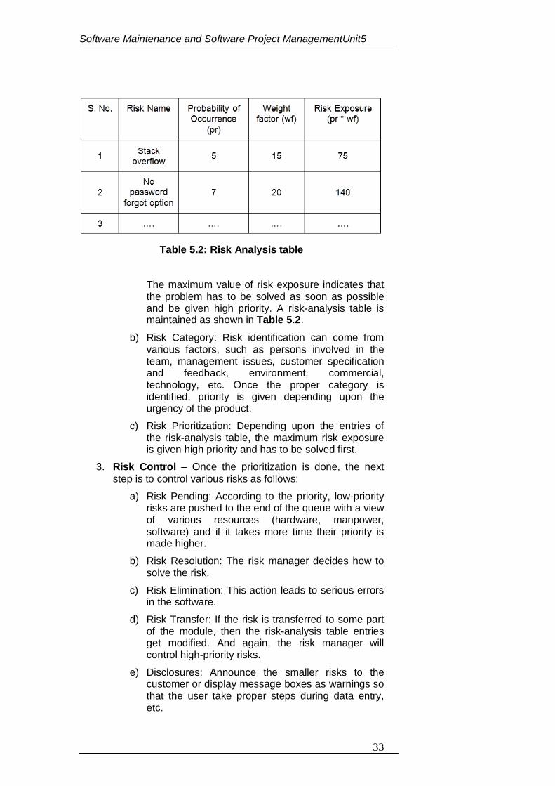
Software Maintenance and Software Project ManagementUnit5
33
Table 5.2: Risk Analysis table
The maximum value of risk exposure indicates that the problem has to be solved as soon as possible and be given high priority. A risk-analysis table is maintained as shown in Table 5.2.
b) Risk Category: Risk identification can come from various factors, such as persons involved in the team, management issues, customer specification and feedback, environment, commercial, technology, etc. Once the proper category is identified, priority is given depending upon the urgency of the product.
c) Risk Prioritization: Depending upon the entries of the risk-analysis table, the maximum risk exposure is given high priority and has to be solved first.
3. Risk Control – Once the prioritization is done, the next step is to control various risks as follows:
a) Risk Pending: According to the priority, low-priority risks are pushed to the end of the queue with a view of various resources (hardware, manpower, software) and if it takes more time their priority is made higher.
b) Risk Resolution: The risk manager decides how to solve the risk.
c) Risk Elimination: This action leads to serious errors in the software.
d) Risk Transfer: If the risk is transferred to some part of the module, then the risk-analysis table entries get modified. And again, the risk manager will control high-priority risks.
e) Disclosures: Announce the smaller risks to the customer or display message boxes as warnings so that the user take proper steps during data entry, etc.
Software Maintenance and Software Project ManagementUnit5
34
f) Risk not Solvable: If a risk takes more time and more resources, then it is dealt with in its totality on the business side of the organization and thereby the customer is notified, and the team member proposes an alternate solution. There is a slight variation in the customer specifications after consultation.
4. Risk Recovery –
a) Full: The risk-analysis table is scanned and if the risk is fully solved, then the corresponding entry is deleted from the table.
b) Partial: The risk-analysis table is scanned and due to partially solved risks, the entries in the table are updated and thereby priorities are also updated.
c) Extra/alternate features: Sometimes it is difficult to remove risks, and in that case, we can add a few extra features, that solve the problem. Therefore, some coding is done to resolve the risk this is later documented or the customer is notified.
Sources of Risks – There are two major sources of risks:
1. Generic Risks: Generic risks are the risks common to all software projects. For example, requirement misunderstanding, allowing insufficient time for testing, losing key personnel, etc.
2. Project-Specific Risks: A vendor may be promising to deliver particular software by a particular date, but is unable to do it.
Types of Risks – There are three types of risks:
1. Product Risks: These are the risks that affect the quality or performance of the software being developed. This originates from conditions, such as unstable requirement specifications, not being able to meet the design specifications affecting software performance, and uncertain test specifications. In view of the software product risks, there is a risk of losing the business and facing strained customer relations. For example, CASE tools under performance.
2. Business Risks: These risks affect the organization developing or procuring the software. For example, technology changes and product competition. The top five business risks are:
Building an excellent product or system that no one really wants (market risks).
Software Maintenance and Software Project ManagementUnit5
35
Building a product that no longer fits into the overall business strategy for the company (strategic risk).
Building a product that the sales force does not understand how to sell.
Losing the support of senior management due to a change in focus or a change in people (management risk).
Losing budgetary or personnel commitment (budget risks).
3. Project Risks: These risks affect the project schedule or resources. These risks occur due to conditions and constraints about resources, relationship with vendors and contractors, unreliable vendors, and lack of organizational support. Funding is the significant project risk management has to face. It occurs due to initial budgeting constraints and unreliable customer payments. For example, staff turnover, management change, hardware uninvertibility.
Software Maintenance and Software Project ManagementUnit5
36
3. Fill in the blanks:
(a) ______ tools assist software engineering managers and practitioners in every software process activity.
(b) Upper CASE tools mainly focus on the _______ and _______ phases of software development.
(c) Software project estimation is the process of __________ various resources required for the completion of a project.
(d) Customer _________ and system _________ form a baseline for estimating the size of software.
(e) The schedule for a project will generally depend on ______ resources involved in a process.
(f) ______ is an algorithmic software cost estimation model.
(g) Risk management is a _______ process based on the application of ________, ________, ________ and ______.
(h) _______ value of risk exposure indicates that the problem has to be solved as soon as possible and be given high ________.
(i) ________ are the risks that affect the quality or performance of the software being developed.
(j) ________ risks affect the project schedule or resources.
CHECK YOUR PROGRESS
Software Maintenance and Software Project ManagementUnit5
37
5.14 LET US SUM UP Software evolution is the phase in which significant
changes to the software architecture and functionality may be made.
Software maintenance is a very broad activity often
defined as including all work made on a software system after it becomes operational.
Preventive maintenance makes changes to computer
programs so that they can be more easily corrected, adapted, and enhanced.
Corrective maintenance includes all the changes made to
remove actual faults in the software. Perfective maintenance refers to changes that originate
from user requests. Software re-engineering is a complex process that re-
engineering tools can only support. Reverse engineering is a process of examination, not a
process of change. Configuration management is the name given to the
general process of managing a changing software system. Version control combines procedures and tools to
manage different versions of configuration objects that are created during the software process.
CASE tools are a class of software that automates many
of the activities involved in various life cycle phases. Estimating the size of the software to be developed is the
very first step to make an effective estimation of the project.
The COCOMO model uses a basic regression formula with
parameters that are derived from historical project data and current as well as future project characteristics.
Software Maintenance and Software Project ManagementUnit5
38
Risk analysis and management are a series of steps that
help a software team to understand and manage uncertainty.
1. (a) requirements (b) maintenance (c) reliability, structure (d) Corrective (e) technical, managerial
2. (a) Reengineering (b) Reverse engineering (c) unstructured, restructured (d) Version management systems (e) Configuration, versions
3. (a) CASE (b) analysis, design (c) estimating (d) requirements, specifications (e) human (f) COCOMO (g) scientific, game theory, decision theory, probability
theory, utility theory (h) maximum, priority (i) Product Risks (j) Project
5.16 FURTHER READINGS
1. Software Engineering – A PRACTITIONER’S APPROACH: Roger S. Pressman.
2. Software Engineering: Ian Sommerville. 3. Software Engineering and Testing: Bharat Bhushan
Agarwal, Sumit Prakash Tayal. 4. Software Engineering: A. A. Puntambekar. 5. Software Engineering Economics, Barry Boehm.
5.15 ANSWERS TO CHECK YOUR PROGRESS
Software Maintenance and Software Project ManagementUnit5
39
1. Describe Software Evolution. 2. What do you mean by Software maintenance? What are
the Software maintenance categories? 3. Write a note on Software Cost.
4. Explain the process of Software Re-engineering and the
activities associated with it. 5. Write a note on Reverse-engineering.
6. Explain the Software Configuration management activities.
7. Describe the Change control process with diagram.
8. Explain Software version control.
9. What are CASE tools? Explain their types.
10. Describe the Project Estimation process.
11. Explain how the different Software development
parameters are estimated.
12. Explain the COCOMO model.
13. What is Risk Analysis and Management? State its importance.
14. Explain the Risk Management categories
15. What are the different types of risks associated with a Software project?
5.17 POSSIBLE QUESTIONS


![Master of Computer Applications Semester-II Subject … From:[ ] Page 1 Gujarat Technological University Master of Computer Applications Semester-II Subject Name: Software Lab (DBMS:](https://static.fdocuments.in/doc/165x107/5aa2e1fc7f8b9a80378d91ae/master-of-computer-applications-semester-ii-subject-from-page-1-gujarat.jpg)