Massachusetts Institute of Technology Department of...
12
Massachusetts Institute of Technology Department of Electrical Engineering and Computer Science 6.115 Microprocessor Project Laboratory Connecting your PSoC Evaluation Board It is easy and fun to avoid blowing up your PSoC board. Be careful with the board and it will serve you long after you have taken 6.115. The most common reasons that a PSoC evaluation board is destroyed include: 1. The evaluation board is connected to an external IC, computer, or other device but there is no common ground connection between the two systems. 2. Excessive voltage is applied to an evaluation board pin. 3. Two different forms of power are applied to the board. Make CERTAIN that you have a common ground connection between your PSoC and your external components like your R31JP or lab kit. Make CERTAIN that you do NOT apply more than 5 volts to any 5 volt-rated PSoC pin, and do not mix 3.3 and 5 volt signals. If you do not understand these points, ASK us before experimenting with your evaluation board. To assist you in using your PSoC evaluation board with your 6.115 lab kit, we will make a power cable for the PSoC board. If used correctly, this power cable will ensure that your PSoC is properly grounded to your kit. Let's construct a little demonstration that will show you how to use your PSoC Evaluation Board with the lab kit and the R31JP. Our plan is: • The R31JP will emit a message at 9600 baud over it's normal RS232 serial connector (the same 9 pin D-Sub we use to connect to a PC through a serial cable.). • The R31JP will be powered "as normal" over the Blackbird power cable. • The transmitting program for the R31JP has been burned into the ROM, replacing MINMON with a transmitting program you can find on the course website. • The PSoC evaluation board will be powered by 5 volts and ground from the Blackbird over a USB connector that you will add to your kit. • A serial cable will connect the PSoC to the R31JP. The PSoC will receive the message from the R31JP and display this message on the PSoC Evaluation Board LCD. Begin by constructing a kit USB power connector that will allow you to use your kit to power the PSoC evaluation board.
Transcript of Massachusetts Institute of Technology Department of...
Massachusetts Institute of Technology Department of Electrical Engineering and Computer Science
6.115 Microprocessor Project Laboratory
Connecting your PSoC Evaluation Board
It is easy and fun to avoid blowing up your PSoC board. Be careful with the board and it will serve you long after you have taken 6.115. The most common reasons that a PSoC evaluation board is destroyed include:
1. The evaluation board is connected to an external IC, computer, or other device but there is no common ground connection between the two systems.
2. Excessive voltage is applied to an evaluation board pin. 3. Two different forms of power are applied to the board.
Make CERTAIN that you have a common ground connection between your PSoC and your external components like your R31JP or lab kit. Make CERTAIN that you do NOT apply more than 5 volts to any 5 volt-rated PSoC pin, and do not mix 3.3 and 5 volt signals. If you do not understand these points, ASK us before experimenting with your evaluation board. To assist you in using your PSoC evaluation board with your 6.115 lab kit, we will make a power cable for the PSoC board. If used correctly, this power cable will ensure that your PSoC is properly grounded to your kit. Let's construct a little demonstration that will show you how to use your PSoC Evaluation Board with the lab kit and the R31JP. Our plan is:
• The R31JP will emit a message at 9600 baud over it's normal RS232 serial connector (the same 9 pin D-Sub we use to connect to a PC through a serial cable.).
• The R31JP will be powered "as normal" over the Blackbird power cable. • The transmitting program for the R31JP has been burned into the ROM, replacing MINMON
with a transmitting program you can find on the course website. • The PSoC evaluation board will be powered by 5 volts and ground from the Blackbird over a
USB connector that you will add to your kit. • A serial cable will connect the PSoC to the R31JP. The PSoC will receive the message from the
R31JP and display this message on the PSoC Evaluation Board LCD. Begin by constructing a kit USB power connector that will allow you to use your kit to power the PSoC evaluation board.

Please begin here: 1. See Professor Leeb during office hours for header strip and a connector board, shown below.
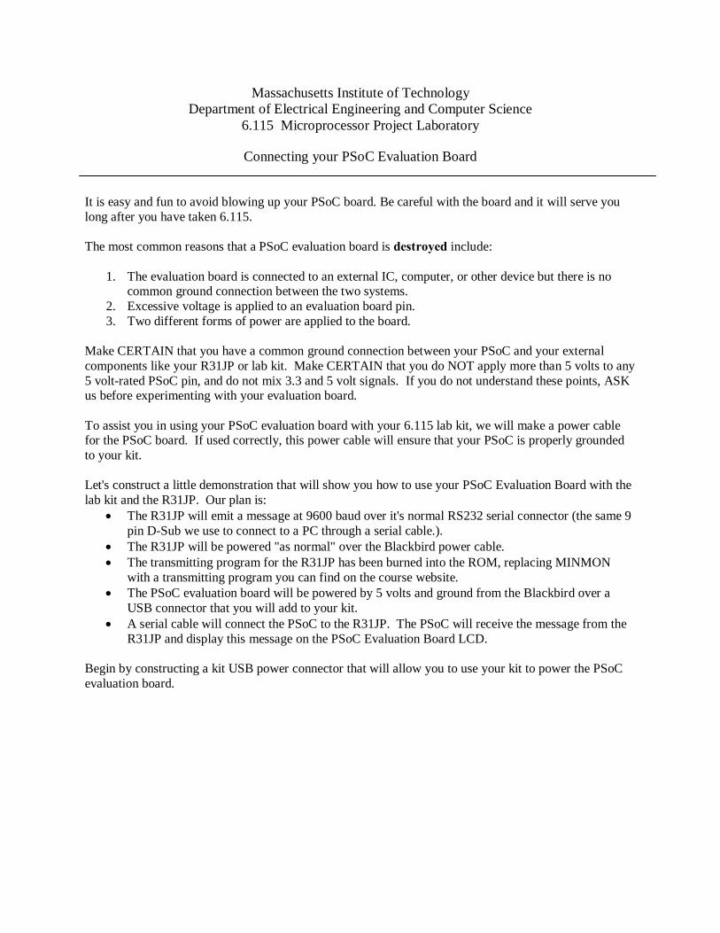
2. Mechanically assemble the parts:

3. Solder the parts:

4. Install the connector board, bypass cap, power wiring, and PSoC USB Cable on your kit. Do NOT connect your PSoC evaluation board to anything yet.
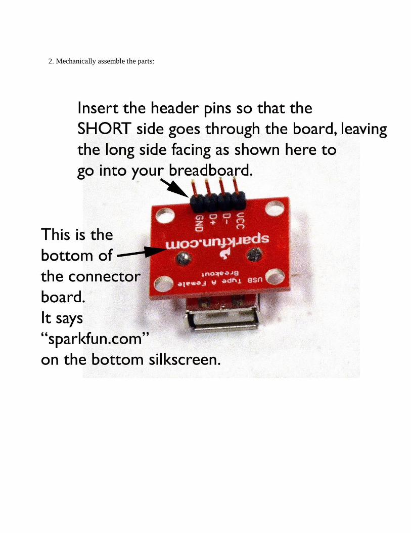
5. Secure the USB cable when installed on your kit:

NOW STOP! Bring your kit to a staff member. Demonstrate that you have Vcc and GND connected to 5 volts. Do NOT plug in your PSOC evaluation board. Demonstrate that you have NOTHING connected to the D+ and D- pins on the power connector board. WITH A STAFF MEMBER, after verifying everything above, then plug in your PSOC evaluation board using the mini-USB connector farthest over on the board, as always: Make sure your PSOC evaluation board powers up.

Once your kit has been modified to provide USB power to the PSOC, you can now connect your PSOC to your R31JP using a serial cable and a NULL Modem connector: You can read about the "NULL modem" or "CROSS CABLE" here: http://www.ethernut.de/en/documents/rs232primer.html The connection you are looking for is the simple "3-wire cross cable" described on this website. WE WILL HAVE NULL MODEM ADAPTERS AVAILABLE FOR USE IN THE LABORATORY, YOU DO NOT HAVE TO MAKE THIS NULL MODEM CABLE. On the demonstration kit, the R31JP is running with a program that uses our SNDCHR routine (from MINMON and the typewriter) to repetitively send a message at 9600 baud. The PSoC evaluation board is running a CREATOR project that READS the PSoC Evaluation Board RS232 receive line at 9600 baud, and displays the received text from the R31JP on the PSoC LCD display. Here's a close up view of the PSoC evaluation board RS232 connector and breadboard:
RS232 LINE DRIVER (Like the MAXIM MAX232 on the R31JP).
Jumper wire that you add to connect the TTL "receive" line of the RS232 line driver to the Port 6_0 pin. In the CREATOR project, P6_0 is connected to a UART device (like the 16450) that was "dragged" into the design from the CREATOR parts options.
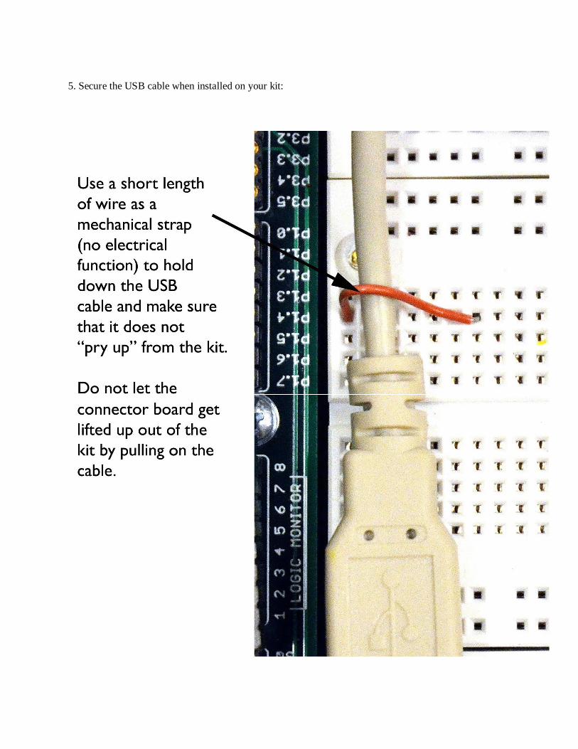
Here’s a mighty Blackbird with the R31JP sending a serial message to the PSOC. You need to use the NULL modem block as shown in the picture.

Here’s a closeup of the NULL modem block between the R31JP and the serial cable:
On the demo kit, you will see the PSOC displaying the message it receives from the R31JP:

Note: If you want to drive external chips with your PSOC, e.g., if you were trying to connect an 8254 to your PSOC (which would probably be silly, since you could drag a timer down in your PSOC design, but let's pretend), then you would want the PSOC and the logic 8254 to both be running off 5 volt rails. The PSOC comes from the "factory" set for 3.3 volt operation. You can make the PSOC I/O pins work for 5 volts by moving the jumpers J10 and J11 on the board. See page 16 in the attached manual. The photo below shows jumpers J10 and J11 “moved” so that the board is running from 5 volts and ready to interface with 5 volt logic on your kit:
POP QUIZ: See if you understand what you've just made, and how to extend it!
QUESTION: Suppose you wanted to connect your PSoC evaluation board to an AMULET module. How would you do it? ANSWER: There's more than one way! The easiest plan, given what you've just seen, is to connect the Amulet RS232 cable connector to the PSoC RS232 cable connector. Make sure the AMULET switch is set to "PC" (not "KIT") so that the cable connector is ready for use. You MUST use a null modem adapter in this case. Like the R31JP, and the PSoC evaluation board, the AMULET has a "female" D-SUB RS232 connector - it is an RS232 "peripheral". A PC has a male D-SUB RS232 connector - it is an RS232 "host". When we connect two RS232 peripherals using the serial cable and DSUB connectors, e.g., R31JP to PSoC, PSoC to Amulet, R31JP to Amulet, then we must use a NULL modem cable. When we connect an RS232 "peripheral" to an RS232 "host", we only need to use a regular serial cable, e.g., R31JP to PC, Amulet to PC, etc. The RS232 cable ensures that both systems connected to each other are grounded together (through pin 5 on the cable connectors). Second approach: To connect the PSoC evaluation board to the Amulet, you could skip all serial cables. In this case, you would switch the Amulet to "kit", and use the TX, RX and GND wires to connect to the PSoC evaluation board breadboard in the middle of the board. MAKE SURE THAT THE GROUNDS ARE CONNECTED BETWEEN THE AMULET AND THE PSoC in this case. You have to ensure this on the breadboard. QUESTION: Suppose you used the PSoC eval breadboard to connect a PSoC pin to TX on the RS232 connector, and another PSoC pin to RX on the RS232 connector, and then programmed the PSoC to type the ASCII table to the RS232 DSUB connector. How would you connect the PSoC to the PC to see the ASCII table in a windows terminal program? ANSWER: Use a regular serial cable. Plug one end into the computer (as usual), and the other end into the programmed PSoC. The cable grounds the two systems. No NULL modem is needed, as the PC RS232 connection is male, and the PSoC is female. QUESTION: You want to connect your PSoC to an IC on your lab kit. What do you do? ANSWER: Power your PSoC using your PSoC Kit Power Cable that you just made. This will ensure at least one ground connection between your PSoC evaluation board and your kit. Now, an IC connected to power and ground on your kit can be connected to PSoC pins by connecting wires from your kit breadboard to your PSoC evaluation board breadboard and associated PSoC pin headers. Make sure the PSoC is running from the same voltage as your chip, e.g., 5 volts if you are using 5 volt logic chips. QUESTION: What do you do if you're confused? ANSWER: ASK THE STAFF FOR HELP BEFORE YOU BLOW UP YOUR PSoC ☺!