Mass Transfer Performance of Porous Nickel Manufactured...
8
Mass Transfer Performance of Porous Nickel Manufactured by Lost Carbonate Sintering Process Pengcheng Zhu* and Yuyuan Zhao Open cell porous metals are excellent electrode materials due to their unique electrochemical properties. However, very little research has been conducted to date on the mass transport of porous metals manufactured by the space holder methods, which have distinctive porous structures. This paper measures the mass transfer coefficient of porous nickel manufactured by the Lost Carbonate Sintering process. For porous nickel samples with a porosity of 0.55–0.75 and a pore size of 250–1500 mm measured at an electrolyte flow velocity of 1–12 cm s 1 , the mass transfer coefficient is in the range of 0.0007–0.014 cm s 1 , which is up to seven times higher than that of a solid nickel plate electrode. The mass transfer coefficient increases with pore size but decreases with porosity. The porous nickel has Sherwood numbers considerably higher than the other nickel electrodes reported in the literature, due to its high real surface area and its tortuous porous structure, which promotes turbulent flow. 1. Introduction Porous metals have attracted considerable attention in academia and industry due to their unique combinations of material and structural characteristics, including high surface area, good catalytic ability, high permeability, light weight, good mechanical properties, and so on. [1–9] Open-cell porous metals have been regarded as excellent electrode materials in energy generation and storage. [9–12] Mass transfer in porous electrodes, that is, the movement of a chemical species from bulk solution to the surface of porous matrix, [13] is critical for the electrochemical reaction, because it is normally the rate-determining step. [14] According to Fick’s law, the rate of mass transfer is proportional to the difference between the concentrations in the bulk solution and at the electrode surface and the interfacial area, with the proportionality coefficient being referred to as mass transfer coefficient. The mass transfer coefficient has a significant effect on the performance of the porous electrode. The mass transfer performance of an electrode is often characterized by the product of mass transfer coefficient and effective surface area of the electrode. The mass transfer property of various porous metal electrode materials has been studied during the past few decades. Marracino et al. [15] studied the mass transfer perfor- mance of a porous nickel with a high porosity (0.95–0.96) and found that the mass transfer performance of the porous nickel electrodes is about 10 times higher than that of the micromesh expanded nickel electrodes. Langlois and Coeuret [16] and Connect et al. [17] studied the SOR- AREC porous nickel which is manufac- tured by a metal decomposition method. [18] They reported that the mass transfer coefficient of this type of porous nickel decreases with pore size. Zhou et al. [19] investigated porous copper fiber sintered felt (PCFSF) with three different porosities (0.7, 0.8, and 0.9) and found that a porosity of 0.8 gave the best mass transfer property. The good mass transport performance of porous metals is mainly derived from their high surface areas. Recio et al. [20] demonstrated that a nickel electrode made by electrodepositing nanostructured Ni on a stainless steel plate had mass transfer performance nearly 23 times that of a mirror polished nickel electrode, due to increased effective surface area. The mass transfer performance of electrodes is also affected by fluid conditions. Using turbulence promoters (TP) can increase the mass transfer coefficient by 1.7–3.8 times. [20–22] Increasing the electrolyte flow velocity can improve the mass transfer performance, but it is not always feasible due to high flow resistance and pumping power constraints. [23] Porous structures vary dramatically with manufacturing processes. [9,24–26] Although several types of porous metals have been demonstrated to have attractive electrochemical proper- ties, no research has been published to date on the mass transfer properties of porous metals manufactured by the space holder methods. This type of porous metals has unique porous structures with high specific surface areas and is expected to have superior mass transfer performance as electrode materials. [27] This paper investigates the mass transfer coefficient of porous nickel manufactured by t12he Lost Carbonate Sintering (LCS) process at different electrolyte flow velocities. The LCS process is a representative space holder method for manufacturing porous P. Zhu, Prof. Y. Zhao School of Engineering, University of Liverpool, Liverpool L69 3GH, UK E-mail: [email protected] The ORCID identification number(s) for the author(s) of this article can be found under https://doi.org/10.1002/adem.201700392. © 2017 The Authors. Published by WILEY-VCH Verlag GmbH & Co. KGaA, Weinheim. This is an open access article under the terms of the Creative Commons Attribution-NonCommercial-NoDerivs License, which permits use and distribution in any medium, provided the original work is properly cited, the use is non-commercial and no modifications or adaptations are made. DOI: 10.1002/adem.201700392 Mass Transfer Coefficient www.aem-journal.com FULL PAPER Adv. Eng. Mater. 2017, 19, 1700392 1700392 (1 of 8) © 2017 The Authors. Published by WILEY-VCH Verlag GmbH & Co. KGaA, Weinheim
Transcript of Mass Transfer Performance of Porous Nickel Manufactured...

Mass Transfer Coefficient www.aem-journal.com
FULL PAPER
Mass Transfer Performance of Porous NickelManufactured by Lost Carbonate Sintering Process
Pengcheng Zhu* and Yuyuan Zhao
Open cell porous metals are excellent electrode materials due to their uniqueelectrochemical properties. However, very little research has been conductedto date on the mass transport of porous metals manufactured by the spaceholder methods, which have distinctive porous structures. This papermeasures the mass transfer coefficient of porous nickel manufactured by theLost Carbonate Sintering process. For porous nickel samples with a porosityof 0.55–0.75 and a pore size of 250–1500mm measured at an electrolyte flowvelocity of 1–12 cm s�1, the mass transfer coefficient is in the range of0.0007–0.014 cm s�1, which is up to seven times higher than that of a solidnickel plate electrode. The mass transfer coefficient increases with pore sizebut decreases with porosity. The porous nickel has Sherwood numbersconsiderably higher than the other nickel electrodes reported in the literature,due to its high real surface area and its tortuous porous structure, whichpromotes turbulent flow.
1. Introduction
Porous metals have attracted considerable attention in academiaand industry due to their unique combinations of material andstructural characteristics, including high surface area, goodcatalytic ability, high permeability, light weight, goodmechanicalproperties, and so on.[1–9] Open-cell porous metals have beenregarded as excellent electrode materials in energy generationand storage.[9–12]
Mass transfer in porous electrodes, that is, the movement of achemical species from bulk solution to the surface of porousmatrix,[13] is critical for the electrochemical reaction, because it isnormally the rate-determining step.[14] According to Fick’s law, therate of mass transfer is proportional to the difference between theconcentrations in the bulk solution and at the electrode surfaceand the interfacial area, with the proportionality coefficientbeing referred to as mass transfer coefficient. The mass transfer
P. Zhu, Prof. Y. ZhaoSchool of Engineering, University of Liverpool,Liverpool L69 3GH, UKE-mail: [email protected]
The ORCID identification number(s) for the author(s) of this articlecan be found under https://doi.org/10.1002/adem.201700392.
© 2017 The Authors. Published by WILEY-VCH Verlag GmbH & Co.KGaA, Weinheim. This is an open access article under the terms of theCreative Commons Attribution-NonCommercial-NoDerivs License,which permits use and distribution in any medium, provided theoriginal work is properly cited, the use is non-commercial and nomodifications or adaptations are made.
DOI: 10.1002/adem.201700392
Adv. Eng. Mater. 2017, 19, 1700392 1700392 (1 of 8) © 2017 The Authors. Pub
coefficient has a significant effect on theperformance of the porous electrode.
The mass transfer performance of anelectrode is often characterized by theproduct of mass transfer coefficient andeffective surface area of the electrode. Themass transfer property of various porousmetal electrode materials has been studiedduring the past few decades. Marracinoet al.[15] studied the mass transfer perfor-mance of a porous nickel with a highporosity (0.95–0.96) and found that themass transfer performance of the porousnickel electrodes is about 10 times higherthan that of the micromesh expandednickel electrodes. Langlois and Coeuret[16]
and Connect et al.[17] studied the SOR-AREC porous nickel which is manufac-tured by a metal decomposition method.[18]
They reported that the mass transfercoefficient of this type of porous nickel
decreases with pore size. Zhou et al.[19] investigated porouscopper fiber sintered felt (PCFSF) with three different porosities(0.7, 0.8, and 0.9) and found that a porosity of 0.8 gave the bestmass transfer property.
The good mass transport performance of porous metals ismainly derived from their high surface areas. Recio et al.[20]
demonstrated that a nickel electrode made by electrodepositingnanostructured Ni on a stainless steel plate had mass transferperformance nearly 23 times that of a mirror polished nickelelectrode, due to increased effective surface area. The masstransfer performance of electrodes is also affected by fluidconditions. Using turbulence promoters (TP) can increase themass transfer coefficient by 1.7–3.8 times.[20–22] Increasingthe electrolyte flow velocity can improve the mass transferperformance, but it is not always feasible due to high flowresistance and pumping power constraints.[23]
Porous structures vary dramatically with manufacturingprocesses.[9,24–26] Although several types of porous metals havebeen demonstrated to have attractive electrochemical proper-ties, no research has been published to date on the masstransfer properties of porous metals manufactured by the spaceholder methods. This type of porous metals has unique porousstructures with high specific surface areas and is expectedto have superior mass transfer performance as electrodematerials.[27]
This paper investigates the mass transfer coefficient of porousnickel manufactured by t12he Lost Carbonate Sintering (LCS)process at different electrolyte flow velocities. The LCS process isa representative space holder method for manufacturing porous
lished by WILEY-VCH Verlag GmbH & Co. KGaA, Weinheim

www.advancedsciencenews.com www.aem-journal.com
Adv.
metals.[28,29] The LCS porous nickel has a highly controllableopen-cell structure with a wide range of porosity and pore size.This work studies the effects of porosity and pore size on masstransfer coefficient and compares the mass transfer perfor-mance of the LCS nickel with other porous nickel electrodesreported in the literature.
Figure 2. Typical current vs potential plot for LCS porous nickel sample inreal surface area measurement at a scan rate range of 0.05–0.5 V s�1.
2. Experimental MethodsPreparation of Nickel Electrodes: A solid nickel plate with a thickness of
1mm and surface area of 2.8 cm2 was used as a comparator. It was firstground by silicon carbide papers (grades 120, 600, and 1200) to achieve afinish about 15mm, then polished by oil-lubricated diamond compoundson a woven cloth substrate to achieve a finish of 1mm, and finally polishedby 0.04mm silk-type cloth pad before use.
Eighteen porous nickel samples, with porosity ranging from 0.55 to0.75 and pore size ranging from 250 to 1500mm, were manufactured bythe LCS process.[28,29] The samples were cut by an electrical dischargemachine (Prima E250, ONA Ltd., Bristol, UK) into a cylindrical shape witha diameter of 6mm and a length of 5mm. Figure 1 shows a typicalmicrostructure of the LCS porous nickel.
Before electrochemical tests, the porous nickel and nickel platesamples were first washed by 10% HCL solution to remove oxides on thesurface and then rinsed in distilled water. The porous samples wereplaced in an agitated sacrificial electrolyte solution before beingtransferred to the electrochemical cell, in order to improve the infiltrationof electrolyte in the pores.
Surface Areas Measurement: The geometric surface area of the LCSporous nickel samples was measured by the quantitative stereologymethod. The real surface area was measured by the double layercapacitance method. The detailed information of the measurementmethods can be seen in published work.[1] For real surface areameasurement, it should be noticed that the double layer capacitance ofthe LCS porous nickel was equal to half of the difference rather than thedifference between the charge and discharge current over the applied scanrate. A typical plot for the LCS porous nickel sample in real surface areameasurement at a scan rate range of 0.05–0.5 V s�1 can be seen inFigure 2. The counter electrode was Pt coil and the reference electrodewas Saturated Calomel Electrode (SCE). The electrolyte was 8M KOH.The specific capacitance of nickel in 8M KOH is about 28mF cm�2.[30]
Mass Transfer Measurement: Experimental Apparatus: Figure 3a is aschematic diagram of the mass transfer experimental apparatus. Itconsists of a plastic electrolyte reservoir, a peristaltic pump (Masterlex L/SComputer-Compatible Digital Pump), a three electrode cell, a potentiostat(Autolab PGSTAT101), and a computer. The sample to be tested served as
Figure 1. SEM image of the porous nickel manufactured by the lostsintering carbonate process.
Eng. Mater. 2017, 19, 1700392 1700392 (2 of 8) © 2
the working electrode. A water proof shrinkage tube was used to connectthe porous nickel sample to an acrylic tube with an outer diameter of6mm (Figure 3b). The nickel plate was inserted into the acrylic tube,parallel to the tube and the flow of the electrolyte (Figure 3c). Theelectrolyte was forced to pass through the porous electrode, or flow pastthe solid plate electrode, and exhausted by the peristaltic pump.
Limiting Current Technique: The limiting current technique was usedto measure the mass transfer coefficient. The electrochemical reactionused in this work was the reduction of the ferricyanide ion:
Fe CNð Þ6� �3� þ e� ! Fe CNð Þ6
� �4� ð1ÞA 1M Na2CO3 was used as the background electrolyte. In
characterizing the nickel plate electrode, the electrolyte contained10�3MK3Fe(CN)6 and 10�2MK4Fe(CN)6. In characterizing the LCSporous nickel electrodes, the concentrations of the reactive species werereduced by 10 times and the electrolyte contained 10�4MK3Fe(CN)6 and10�3MK4Fe(CN)6. This is because porous metals have high surfaceareas,[1] which can generate high currents, causing distortions in themeasurements due to uncompensated solution resistance. Reducingthe concentrations of the reactive species eliminated the effect ofuncompensated solution resistance.[31] The limiting current wasmeasured by linear sweep voltammetry at a scan rate of 5mV s�1, withan applied potential in the range from 0.2 V to �1.2 V.
Determination of Mass Transfer Coefficient: Figure 4 shows a typicalcurrent-potential plot of a LCS porous nickel electrode. There are threeregions in the curve, that is, hydrogen evolution, mass transfer control,and mixed control regions, which signify different transfer mechanisms.The limiting current, IL, was determined from the mass transfer regionand the mass transfer coefficient, k, was calculated by:
k ¼ ILnFAC
ð2Þ
where n is the number of electrons exchanged in the reaction (n¼ 1 forEq. 2), F is the Faraday constant, A is the real surface area of the workingelectrode, and C is the bulk concentration of the electroactive species.The error of the mass transfer coefficient value mainly resulted from theerror of the experimental measurement of limiting current, which wasabout 5%.
3. Results and Discussion
3.1. Effects of Porosity and Pore Size
Table 1 shows the structural properties of the LCS porous nickelsamples, including nominal porosity, volumetric geometric
017 The Authors. Published by WILEY-VCH Verlag GmbH & Co. KGaA, Weinheim

Figure 3. Schematics of a) mass transfer experimental apparatus, b) porous nickel working electrode, and c) nickel plate working electrode: 1) electrolytereservoir, 2) pumping pipe, 3) waste solution reservoir, 4) peristaltic pump, 5) working electrode, 6) reference electrode (SCE), 7) counter electrode(platinum coil), 8) glass beaker, 9) wire, 10) potentiostat, 11) computer, 12) acrylic tube, 13) water proof shrinkage tube, 14) LCS porous nickel sample,15) nickel wire, and 16) solid nickel plate.
www.advancedsciencenews.com www.aem-journal.com
surface area, and volumetric real surface area. The actualporosity of a sample is slightly different from the nominalporosity, depending on the manufacturing conditions. Volumet-ric surface areas designate surface areas per unit volume ofsample. The geometric surface area is the surface area of theprimary pores formed by the decomposition of the space holderparticles, assuming a smooth surface. The real surface area takesinto account all the surface area that can be reached by theelectrolyte and contribute to the electrochemical reactions.
Figure 5 shows the variations of the mass transfer coefficientwith sample porosity at different electrolyte flow rates in therange of 0.28–1.87mL s�1 for LCS porous nickel samples withvarious pore size ranges. For the conditions investigated in thiswork, the mass transfer coefficient of the LCS porous nickel is inthe range of 0.00069–0.0135 cm s�1. For any given electrolyteflow rate, the mass transfer coefficient decreases with porosity,more pronounced at high electrolyte flow rates than at low flowrates. Comparing Figure 5ad shows that the mass transfercoefficient increases with pore size for the samples with a fixedporosity and electrolyte flow rate. The reason behind the effectsof porosity and pore size will be discussed in Section 3.3.
Figure 4. Typical current versus potential plot for the reduction ofFe(CN)6
�3 in 10�4MK3Fe(CN)6þ 10�3MK4Fe(CN)6þ 1M Na2CO3 at aporous nickel electrode with a scan rate of 0.005 V s�1.
Adv. Eng. Mater. 2017, 19, 1700392 1700392 (3 of 8)
3.2. Effect of Flow Velocity
It is shown in Figure 5 that the mass transfer coefficient of theLCS porous nickel samples increases with the electrolyte flowrate. While it is convenient to describe the mass transferperformance of a porous sample at an overall electrolyte flowrate, the effect of flow rate is better understood by the resultantflow velocity in the pore channels. The internal flow velocity, u,can be determined by:
u ¼ QACe
ð3Þ
where Q is the flow rate of the electrolyte, AC (0.283 cm2) is thecross-sectional area of the flow channel, that is, the acrylic tube,and e is the porosity of the porous nickel sample.
Figure 6 shows the variations of the mass transfer coefficientof the porous nickel samples with internal flow velocity, plottedin the logarithmic scale. The data for the solid nickel plate arealso presented for comparison. The mass transfer coefficientincreases exponentially with electrolyte flow velocity, whichagrees well with the literature.[17,20] The relation between masstransfer coefficient, k, and internal flow velocity, u, can bedescribed by[16,17]:
k ¼ aub ð4Þwhere a is a constant associated to the structural properties ofthe working electrode and b is a constant dependent on the
Table 1. Structural properties of the LCS porous nickel samples.
PorosityVolumetric geometric surface
area (cm�1)Volumetric real surface area
(cm�1)
Pore size (mm) 0.55 0.60 0.65 0.70 0.75 0.55 0.60 0.65 0.70 0.75
250–425 68 76 82 90 96 948 789 637 593 457
425–710 42 50 54 56 60 687 632 529 461 342
710–1000 28 – 34 36 42 591 – 619 560 417
1000–1500 20 – 26 30 34 639 – 570 551 325
© 2017 The Authors. Published by WILEY-VCH Verlag GmbH & Co. KGaA, Weinheim

Figure 5. Mass transfer coefficient as a function of porosity at different electrolyte flow rates for the LCS porous nickel samples with various pore sizes: a)250–425mm, b) 425–710mm, c) 710–1000mm, and d) 1000–1500mm.
www.advancedsciencenews.com www.aem-journal.com
Adv.
hydrodynamic regime. The value of the exponent b can serve asan indicator of the nature of the flow.[20] The value of b is higherin a turbulent flow than in a laminar flow.[32]
3.3. Interpretation of the Effects of Porosity and Pore Size
Figure 7 shows the variations of the pre-exponential constant, a,and the exponent, b, in Equation 4 as a function of geometricsurface area for the LCS porous nickel samples. The values of aand b were obtained from Figure 6 and the values of thegeometric surface area are shown in Table 1. It is shown that thepre-exponential constant a and the exponent b are stronglycorrelated with the geometric surface area. The higher thevolumetric geometric surface area, the lower the pre-exponentialconstant a and the exponent b.
The effect of geometric surface area on the constant a mayarise from its effect on the spatial distribution of theelectrolyte in the porous channels. For a fixed porosity,different geometric surface areas lead to different depths ofelectrolyte in the porous channel. A higher volumetricgeometric surface area means a thinner electrolyte near thesurface of the metal matrix, that is, the electrolyte beingspread more thinly against the surface. If the depth of theelectrolyte becomes comparable to or even thinner than the
Eng. Mater. 2017, 19, 1700392 1700392 (4 of 8) © 2
Nernst diffusion layer,[1,33] it can cause exhaustion of thereactive species. This may effectively lead to a reduced bulkconcentration of the reactive species, which in turn can resultin a reduced pre-exponential constant.
Geometric surface area is probably not a direct causativeparameter for the exponent b. The exponent is an indicator offlow turbulence,[20] which is more likely affected by the tortuosityof the porous structure. Tortuosity of a porous mediumcharacterizes the convoluted pathways, or channels, formedby pores through the porous medium. It is defined as the ratio ofthe average length of pathways between two points to thestraight-line distance between the points in the porous medium.Lower porosities and large pores in LCS porous metals generallyresult in high tortuosity values.[34] At the same time, Lowerporosities and large pores lead to lower volumetric geometricsurface area. A low volumetric geometric surface area istherefore associated with a high tortuosity and high turbulence,resulting in a high exponent value.
Figure 7 also shows that the effects of porosity and pore sizeon the constants are different, although both affect thevolumetric geometric surface area. The pre-exponential constanta increases significantly with pore size but does not changemuch with porosity for any given pore size. The effect of poresize can be explained by the relative magnitudes of the electrolytereservoir and the diffusion layer. On the one hand, smaller pores
017 The Authors. Published by WILEY-VCH Verlag GmbH & Co. KGaA, Weinheim

Figure 6. Mass transfer coefficient as a function of electrolyte flow velocity for the LCS porous nickel samples with pore sizes of: a) 250–425mm,b) 425–710mm, c) 710–1000mm, and d) 1000–1500mm.
www.advancedsciencenews.com www.aem-journal.com
contain smaller pockets of electrolyte and thus thinnerelectrolyte. On the other hand, smaller pores have greatersurface curvatures and consequently thicker diffusion layers.The higher ratios between diffusion layer and electrolyte depthcan lead to more severe exhaustion of reactive species and thusa reduced pre-exponential constant. The exponent b generallydecreases significantly with porosity, but does not change as
Figure 7. Variations of a) pre-exponential constant a and b) exponent b wi
Adv. Eng. Mater. 2017, 19, 1700392 1700392 (5 of 8)
much with pore size for any given porosity. Although the porousnickel samples with the smallest pore size (250–425mm)show lower exponent values, the samples with the other poresizes have similar exponent values. These results indicate thatthe spatial distribution of the electrolyte is mainly influenced bypore size while the flow turbulence is mainly dependent onporosity.
th volumetric geometric surface area.
© 2017 The Authors. Published by WILEY-VCH Verlag GmbH & Co. KGaA, Weinheim

Figure 8. Variation of exponent b with porosity at different pore sizes.
www.advancedsciencenews.com www.aem-journal.com
Adv.
3.4. Comparison with the Solid Nickel Electrode
Figure 6 shows that nearly all the LCS porous nickel sampleshave higher mass transfer coefficients (up to seven times) thanthe solid nickel plate at the same electrolyte flow velocities. Thisis very likely because the LCS porous structure promotes a highlyturbulent flow, which is well known to lead to a high masstransfer coefficient.[32] The exception is the samples with thesmallest pores of 250–425mm at low electrolyte velocities, whichhavemass transfer coefficients similar to those of the nickel plateat the same velocity (Figure 6a). This is because the flow withinthe LCS porous nickel samples with small pores may remainlaminar at low flow velocities, as in the case of the flow on thesurface of a nickel plate.
The mass transfer performance of porous electrodes dependsnot only on the mass transfer coefficient but also on the internalsurface area. The mass transfer performance is described by theproduct of the mass transfer coefficient and the real surface area(kA). The volumes of the porous nickel samples and nickel plateused in this study are almost identical, about 0.14 cm3. Theporous nickel samples have a geometric surface area in the range
Figure 9. Correlation between Sherwood and Reynolds numbers for a) LCS prange in a), the lines correspond to porosities of 0.55, 0.60, 0.70, and 0.75 (froand presence of a TB,[23] nanostructured Ni in the absence and presence o
Eng. Mater. 2017, 19, 1700392 1700392 (6 of 8) © 2
of 2.83–13.56 cm2 and a real surface area in the range of45–135 cm2, which are about 1–5 times and 16–50 times of thesurface area of the solid nickel plate (2.8 cm2). Given that theporous nickel samples have a mass transfer coefficient 1–7 timesof that of the solid nickel plate at the same electrolyte flowvelocities, the mass transfer performance (kA) of the LCS porousnickel can be up to 300 times better than the solid nickel plate.
The limiting current can also be used as a direct indicator ofthe mass transfer performance, provided the electrodes to becompared are measured under the same conditions with thesame electrolyte concentrations. The maximum limiting currentof the porous nickel samples was 0.0131A, which is about 30times of the limiting current of the nickel plate measured at thesame electrolyte velocity (0.0046A). However, the concentrationof Ferricyanide used in the measurements for the nickel platewas 10 times higher than that used in the measurements for theporous nickel samples. The mass transfer performance of theporous nickel is therefore up to 300 times better than the solidnickel plate, the same conclusion as reached by comparing kA.
The value of pre-exponential constant a for the solid nickelworking electrode is 0.00078, which is higher than the a values ofthe LCS porous nickel samples with the smallest pore size(250–425mm) but lower than those of the porous samples withlarger pore sizes (Figure 7a). The value of exponent b for the solidnickel working electrode is 0.37, which is similar to the valuereported in the literature for a fully developed laminar flow(�0.33).[32] This indicates that, in the range of flow velocitystudied in this work (1–12 cm s�1), the electrolyte flow on thesurface of the nickel plate remains laminar. The values of b forthe porous nickel electrodes, however, are much higher, rangingfrom 0.57 to 1.03 (Figure 7b). The flow within the LCS porousstructure can change to turbulence flow, due to the highlytortuous nature of the pore channels.
Figure 8 replots theconstantb values against theporosity valuesof the LCS porous nickel samples. It is interesting to note thatthe trend lines for the samples with pore sizes of 250–425mm,425–710mm, and 710–1000mm approach 0.37 at a porosity of 1,that is, thebvalueof thenickelplate,whichcanbeseenasa “poroussample”with a porosity of 1. The data points for the sampleswith a
orous nickel samples and b) various nickel electrodes. For each pore sizem top to bottom). The legends in b) designate solid Ni plate in the absencef a TB,[20] Ni foam MN020, MN060, and MN100.[17]
017 The Authors. Published by WILEY-VCH Verlag GmbH & Co. KGaA, Weinheim
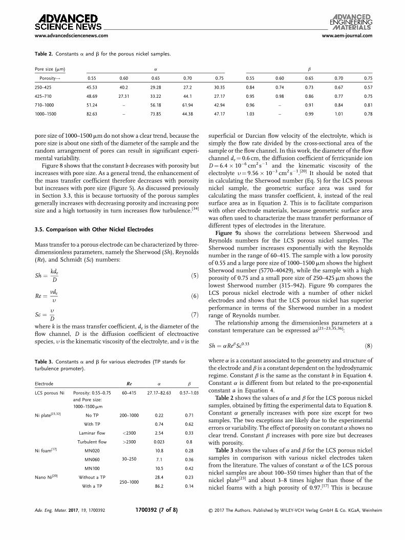
Table 2. Constants a and b for the porous nickel samples.
Pore size (mm) a b
Porosity! 0.55 0.60 0.65 0.70 0.75 0.55 0.60 0.65 0.70 0.75
250–425 45.53 40.2 29.28 27.2 30.35 0.84 0.74 0.73 0.67 0.57
425–710 48.69 27.31 33.22 44.1 27.17 0.95 0.98 0.86 0.77 0.75
710–1000 51.24 – 56.18 61.94 42.94 0.96 – 0.91 0.84 0.81
1000–1500 82.63 – 73.85 44.38 47.17 1.03 – 0.99 1.01 0.78
www.advancedsciencenews.com www.aem-journal.com
pore size of 1000–1500mmdo not show a clear trend, because thepore size is about one sixth of the diameter of the sample and therandom arrangement of pores can result in significant experi-mental variability.
Figure 8 shows that the constant b decreases with porosity butincreases with pore size. As a general trend, the enhancement ofthe mass transfer coefficient therefore decreases with porositybut increases with pore size (Figure 5). As discussed previouslyin Section 3.3, this is because tortuosity of the porous samplesgenerally increases with decreasing porosity and increasing poresize and a high tortuosity in turn increases flow turbulence.[34]
3.5. Comparison with Other Nickel Electrodes
Mass transfer to a porous electrode can be characterized by three-dimensionless parameters, namely the Sherwood (Sh), Reynolds(Re), and Schmidt (Sc) numbers:
Sh ¼ kdeD
ð5Þ
Re ¼ vdey
ð6Þ
Sc ¼ y
Dð7Þ
where k is the mass transfer coefficient, de is the diameter of theflow channel, D is the diffusion coefficient of electroactivespecies, y is the kinematic viscosity of the electrolyte, and n is the
Table 3. Constants a and b for various electrodes (TP stands forturbulence promoter).
Electrode Re a b
LCS porous Ni Porosity: 0.55–0.75
and Pore size:
1000–1500mm
60–415 27.17–82.63 0.57–1.03
Ni plate[23,32] No TP 200–1000 0.22 0.71
With TP 0.74 0.62
Laminar flow <2300 2.54 0.33
Turbulent flow >2300 0.023 0.8
Ni foam[17] MN020
30–250
10.8 0.28
MN060 7.1 0.36
MN100 10.5 0.42
Nano Ni[20] Without a TP250–1000
28.4 0.23
With a TP 86.2 0.14
Adv. Eng. Mater. 2017, 19, 1700392 1700392 (7 of 8)
superficial or Darcian flow velocity of the electrolyte, which issimply the flow rate divided by the cross-sectional area of thesample or the flow channel. In this work, the diameter of the flowchannel de¼ 0.6 cm, the diffusion coefficient of ferricyanide ionD¼ 6:4� 10�6 cm2s�1 and the kinematic viscosity of theelectrolyte y¼ 9:56� 10�3 cm2s�1.[20] It should be noted thatin calculating the Sherwood number (Eq. 5) for the LCS porousnickel sample, the geometric surface area was used forcalculating the mass transfer coefficient, k, instead of the realsurface area as in Equation 2. This is to facilitate comparisonwith other electrode materials, because geometric surface areawas often used to characterize the mass transfer performance ofdifferent types of electrodes in the literature.
Figure 9a shows the correlations between Sherwood andReynolds numbers for the LCS porous nickel samples. TheSherwood number increases exponentially with the Reynoldsnumber in the range of 60–415. The sample with a low porosityof 0.55 and a large pore size of 1000–1500mm shows the highestSherwood number (5770–40429), while the sample with a highporosity of 0.75 and a small pore size of 250–425mm shows thelowest Sherwood number (315–942). Figure 9b compares theLCS porous nickel electrode with a number of other nickelelectrodes and shows that the LCS porous nickel has superiorperformance in terms of the Sherwood number in a modestrange of Reynolds number.
The relationship among the dimensionless parameters at aconstant temperature can be expressed as[21–23,35,36]:
Sh ¼ aRebSc0:33 ð8Þ
where a is a constant associated to the geometry and structure ofthe electrode and b is a constant dependent on the hydrodynamicregime. Constant b is the same as the constant b in Equation 4.Constant a is different from but related to the pre-exponentialconstant a in Equation 4.
Table 2 shows the values of a and b for the LCS porous nickelsamples, obtained by fitting the experimental data to Equation 8.Constant a generally increases with pore size except for twosamples. The two exceptions are likely due to the experimentalerrors or variability. The effect of porosity on constant a shows noclear trend. Constant b increases with pore size but decreaseswith porosity.
Table 3 shows the values of a and b for the LCS porous nickelsamples in comparison with various nickel electrodes takenfrom the literature. The values of constant a of the LCS porousnickel samples are about 100–350 times higher than that of thenickel plate[23] and about 3–8 times higher than those of thenickel foams with a high porosity of 0.97.[17] This is because
© 2017 The Authors. Published by WILEY-VCH Verlag GmbH & Co. KGaA, Weinheim
www.advancedsciencenews.com www.aem-journal.com
Adv.
the LCS porous nickel has a large effective (real) surface area,which is about one to two orders of magnitude higher than itsgeometric surface area (see Table 1). For the nanostructurednickel electrode which was reported with a high effective surfacearea,[20] the values of constant a are comparable to that of the LCSporous nickel samples.
The values of constant b of the LCS porous nickel samples aresimilar to that of the nickel plate under turbulent flow but higherthan that of the nickel plate under laminar flow.[32] They areconsiderably higher than those of the nickel foams[17] and thenanostructured nickel.[20]
4. Conclusions
1)
Eng
The mass transfer coefficient of the LCS porous nickelsamples with a porosity of 0.55–0.75 and a pore size of250–1500mm was measured at an electrolyte flow velocityrange from 1 to 12 cm s�1.
2)
The mass transfer coefficient of the LCS porous nickel is inthe range 0.0007–0.014 cm s�1. It increases with pore sizeand decreases with porosity.3)
At low flow velocities, the mass transfer coefficient is similarto that of the nickel plate. At high flow velocities, it can be upto seven times larger than that of the nickel plate due toturbulence. The mass transfer performance (kA) of the LCSporous nickel samples is up to 300 times better than thenickel plate.4)
The LCS porous nickel has higher Sherwood numbers thanmany other nickel electrodes in the modest range ofReynolds number, due to its high real surface area and itstortuous porous structure, which promotes turbulent flow.Conflict of InterestsThe authors declare no conlfict of interest.
Keywordsporous nickel; mass transfer coefficient; lost carbonate sintering;Sherwood number surface area
Received: April 29, 2017Revised: June 7, 2017
Published online: July 5, 2017
[1] K. K. Diao, Z. Xiao, Y. Y. Zhao, Mater. Chem. Phys. 2015, 162, 571.[2] E. Hern�andez-Nava, C. Smith, F. Derguti, S. Tammas-Williams,
F. L�eonard, P. Withers, I. Todd, R. Goodall, Acta Mater. 2015, 85, 387.
. Mater. 2017, 19, 1700392 1700392 (8 of 8) © 2
[3] N. Hampson, J. Lee, K. Macdonald, J. Electroanal. Chem. InterfacialElectrochem. 1972, 34, 91.
[4] J.-F. Despois, A. Mortensen, Acta Mater. 2005, 53, 1381.[5] Z. Xiao, Y. Zhao, J. Mater. Res. 2013, 28, 2545.[6] A. Otaru, A. R. Kennedy, Scripta Mater. 2016, 124, 30.[7] J.-F. Despois, R. Mueller, A. Mortensen, Acta Mater. 2006, 54,
4129.[8] C. San Marchi, A. Mortensen, Acta Mater. 2001, 49, 3959.[9] M. F. Ashby, T. Evans, N. A. Fleck, J. Hutchinson, H. Wadley,
L. Gibson, Metal Foams: A Design Guide, Elsevier, Oxford, UK 2000.[10] V. Tracey, N. Williams, Electrochem. Technol. 1965, 3, 17.[11] K. C. Liu, M. A. Anderson, J. Electrochem. Soc. 1996, 143, 124.[12] R. Singh, H. Kasana, Appl. Therm. Eng. 2004, 24, 1841.[13] F. P. Incropera, A. S. Lavine, T. L. Bergman, D. P. DeWitt,
Fundamentals of Heat and Mass Transfer, Wiley, New York, US 2007.[14] A. J. Bard, L. R. Faulkner, J. Leddy, C. G. Zoski, Electrochemical
Methods: Fundamentals and Applications, Wiley, New York, 1980.[15] J. Marracino, F. Coeuret, S. Langlois, Electrochim. Acta 1987, 32,
1303.[16] S. Langlois, F. Coeuret, J. Appl. Electrochem. 1989, 19, 51.[17] P. Cognet, J. Berlan, G. Lacoste, P.-L. Fabre, J.-M. Jud, J. Appl.
Electrochem. 1995, 25, 1105.[18] J. Babjak, V. A. Ettel, V. Paserin, Method of forming nickel foam, USA
Patent US4957543 A 1990.[19] W. Zhou, Q. Wang, Q. Qiu, Y. Tang, J. Tu, K. Hui, K. Hui, Fuel 2015,
145, 136.[20] F. Recio, P. Herrasti, L. Vazquez, C. P. de Le�on, F. Walsh, Electrochim.
Acta 2013, 90, 507.[21] C. Brown, D. Pletcher, F. Walsh, J. Hammond, D. Robinson, J. Appl.
Electrochem. 1992, 22, 613.[22] M. Griffiths, C. P. de Le�on, F. C. Walsh, AlChE J. 2005, 51, 682.[23] C. Brown, D. Pletcher, F. Walsh, J. Hammond, D. Robinson, J. Appl.
Electrochem. 1993, 23, 38.[24] J. Park, S. Hyun, S. Suzuki, H. Nakajima, Acta Mater. 2007, 55,
5646.[25] S. Deville, E. Saiz, A. P. Tomsia, Acta Mater. 2007, 55, 1965.[26] D. T. Queheillalt, H. N. Wadley, Acta Mater. 2005, 53, 303.[27] Y. Torres, J. Pav�on, J. Rodríguez, J. Mater. Process. Technol., 2012, 212,
1061.[28] Y. Y. Zhao, T. Fung, L. P. Zhang, F. L. Zhang, Scripta Mater. 2005, 52,
295.[29] Y. Y. Zhao, L. P. Zhang, Proc. Inst. Mech. Eng. Part B: J. Eng. Manuf.
2008, 222, 267.[30] E. Gagnon, J. Appl. Electrochem. 1976, 6, 95.[31] R. E. Smith, T. J. Davies, N. D. B. Baynes, R. J. Nichols, J. Electroanal.
Chem. 2015, 747, 29.[32] D. Sz�anto, P. Trinidad, I. Whyte, F. Walsh, Proc. of 4th European
Symposium on Electrochemical Engineering: Contemporary Trendsin Electrochemical Engineering, European Federation of ChemicalEngineering, Prague, Czech Republic, 1996.
[33] P. Zhu, Y. Zhao, RSC Adv. 2017, 7, 26392.[34] K. K. Diao, L. P. Zhang, Y. Y. Zhao, Measurement, Measurement of
tortuosity of porous Cu using a diffusion diaphragm cell, 2017 110,335.
[35] W. Taama, R. Plimley, K. Scott, Electrochim. Acta 1996, 41, 543.[36] K. Kinoshita, S. Leach, J. Electrochem. Soc. 1982, 129, 1993.
017 The Authors. Published by WILEY-VCH Verlag GmbH & Co. KGaA, Weinheim
![Dynamic Mechanical Behavior of Additively Manufactured Ti6Al4V … · Silva and Ramesh [12] showed ~20% decrease in the yield strength (in compression) for a sintered porous Ti6Al4V](https://static.fdocuments.in/doc/165x107/5f13dc9312eed67a29323cf4/dynamic-mechanical-behavior-of-additively-manufactured-ti6al4v-silva-and-ramesh.jpg)


![Additively manufactured porous tantalum implants.download.xuebalib.com/2ldxRBItS6cG.pdf · [55–62], knee [63–67], spinal [40,68–70] and other orthopedic applications [71]. Despite](https://static.fdocuments.in/doc/165x107/5cc95a1e88c99348378c2bf5/additively-manufactured-porous-tantalum-5562-knee-6367-spinal-406870.jpg)